JP5430231B2 - Imaging device - Google Patents
Imaging device Download PDFInfo
- Publication number
- JP5430231B2 JP5430231B2 JP2009130380A JP2009130380A JP5430231B2 JP 5430231 B2 JP5430231 B2 JP 5430231B2 JP 2009130380 A JP2009130380 A JP 2009130380A JP 2009130380 A JP2009130380 A JP 2009130380A JP 5430231 B2 JP5430231 B2 JP 5430231B2
- Authority
- JP
- Japan
- Prior art keywords
- signal
- stepping motor
- width
- lens
- slit hole
- Prior art date
- Legal status (The legal status is an assumption and is not a legal conclusion. Google has not performed a legal analysis and makes no representation as to the accuracy of the status listed.)
- Active
Links
- 238000003384 imaging method Methods 0.000 title claims description 11
- 238000001514 detection method Methods 0.000 description 68
- 238000000034 method Methods 0.000 description 26
- 230000005284 excitation Effects 0.000 description 12
- 230000003287 optical effect Effects 0.000 description 7
- 238000012545 processing Methods 0.000 description 7
- 230000000630 rising effect Effects 0.000 description 7
- 230000005856 abnormality Effects 0.000 description 6
- 238000010586 diagram Methods 0.000 description 5
- 238000012937 correction Methods 0.000 description 4
- 210000003746 feather Anatomy 0.000 description 4
- 238000004804 winding Methods 0.000 description 4
- 230000002159 abnormal effect Effects 0.000 description 3
- 230000001133 acceleration Effects 0.000 description 2
- 238000006243 chemical reaction Methods 0.000 description 2
- 230000005279 excitation period Effects 0.000 description 2
- 241000499489 Castor canadensis Species 0.000 description 1
- 235000011779 Menyanthes trifoliata Nutrition 0.000 description 1
- 230000015572 biosynthetic process Effects 0.000 description 1
- 239000000470 constituent Substances 0.000 description 1
- 238000007796 conventional method Methods 0.000 description 1
- 230000000694 effects Effects 0.000 description 1
- 238000012986 modification Methods 0.000 description 1
- 230000004048 modification Effects 0.000 description 1
Images


Landscapes
- Lens Barrels (AREA)
- Control Of Stepping Motors (AREA)
Description
本発明は、ステッピングモータを使用してフォーカスレンズ等の可動部を駆動する撮影装置に関する。 The present invention relates to a photographing apparatus that uses a stepping motor to drive a movable part such as a focus lens.
ステッピングモータ(パルスモータとも呼ばれる)は、パルスの入力に応じて所定の回転角(ステップ角度等と呼ばれる)だけ駆動するように構成されたモータである。このようなステッピングモータは、比較的簡単な回路構成で正確な位置制御を実現できるため、位置決めの精度が重要となる各種の装置に用いられている。例えば、特許文献1においては、デジタル複写機等のスキャナ装置における走査部を駆動するためにステッピングモータを用いている。そして、特許文献1においては、走査部の走査位置を検出するために、異なる複数の間隔のスリット孔を有する回転体をエンコーダとして使用し、この回転体によってステッピングモータの回転方向と回転速度を検出して走査部の位置制御を行っている。
A stepping motor (also referred to as a pulse motor) is a motor configured to drive only a predetermined rotation angle (referred to as a step angle or the like) in response to a pulse input. Such a stepping motor can realize accurate position control with a relatively simple circuit configuration, and is therefore used in various devices in which positioning accuracy is important. For example, in
ここで、ステッピングモータにおいても、外乱の影響等によって発生する負荷変動等により脱調が発生する場合がある。このような脱調を検出するために、特許文献1においては、複数の異なる間隔のスリット孔に対応して読み取られる複数のエンコーダ信号(スリット信号)の間隔から脱調等の異常動作を検出できるようにしている。
Here, even in a stepping motor, a step-out may occur due to a load fluctuation or the like generated due to the influence of a disturbance or the like. In order to detect such a step-out, in
特許文献1においては、ステッピングモータをスキャナ装置の走査部を駆動するために用いている。このため、予め決められた一意の定速度でステッピングモータを駆動している。したがって、エンコーダ信号の波形は安定したものとなり、異常を検出することは容易である。
In
しかしながら、ステッピングモータは必ずしも一意の定速度で駆動されるものではない。例えば、ステッピングモータを使用してカメラ等の撮影装置におけるフォーカスレンズを駆動する場合には、最低速度から最高速度までの様々な速度領域でステッピングモータを定速駆動する必要がある。この場合、高速度側では、姿勢や温度などの要因により、駆動したい負荷が変動し、これによってステッピングモータのトルク不足により脱調する可能性がある。また、低速度側では、ステッピングモータが振動的な動作となってエンコーダの出力信号波形が乱れたものとなりやすい。出力信号波形が乱れたものとなった場合には、エンコーダの出力信号波形が正常動作のように見えるパターン化した波形となる可能性もあり、このような出力信号波形からステッピングモータに何らかの異常が発生していることを検出することは困難である。 However, the stepping motor is not necessarily driven at a unique constant speed. For example, when a stepping motor is used to drive a focus lens in a photographing apparatus such as a camera, it is necessary to drive the stepping motor at a constant speed in various speed ranges from the lowest speed to the highest speed. In this case, on the high speed side, there is a possibility that the load to be driven fluctuates due to factors such as posture and temperature, thereby causing a step-out due to insufficient torque of the stepping motor. On the low speed side, the stepping motor is oscillating and the output signal waveform of the encoder tends to be disturbed. If the output signal waveform becomes distorted, the encoder output signal waveform may become a patterned waveform that looks like normal operation, and there is some abnormality in the stepping motor from such output signal waveform. It is difficult to detect what has occurred.
また、特許文献1におけるステッピングモータは、外乱の影響を受けにくい筐体の中に設けられるものでため、安定した動作がえられやすい。これに対し、例えば、撮影装置のフォーカスレンズの駆動にステッピングモータを利用する場合にはステッピングモータが必ずしも外乱の影響を受けにくい位置に設けられているとは限らない。例えば、フォーカス環が外部に露出するような構成である場合も多く、このような場合にはユーザが誤ってフォーカス環に触れる等して、ステッピングモータに脱調が発生する可能性も高い。
In addition, since the stepping motor in
本発明は、上記の事情に鑑みてなされたものであり、外乱の影響を受けやすい場合や、ステッピングモータを複数の速度領域で駆動する場合であっても、ステッピングモータの異常動作を確実に検出できる撮影装置を提供することを目的とする。 The present invention has been made in view of the above circumstances, and reliably detects abnormal operation of a stepping motor even when it is susceptible to disturbances or when the stepping motor is driven in a plurality of speed regions. An object of the present invention is to provide a photographing apparatus capable of performing the above.
上記の目的を達成するために、本発明の第1の態様の撮影装置は、1ステップ単位で入力されるパルス信号に従って回転駆動され、該回転駆動によって当該撮影装置の可動部を駆動するステッピングモータと、上記ステッピングモータの上記1ステップの駆動量に対応する幅を1単位とし、該1単位の整数倍の幅を有するスリット孔であって、2種類以上の異なる幅のスリット孔が形成され、上記ステッピングモータの回転駆動に伴って回転する回転体と、上記スリット孔の有無を読み取って、該スリット孔の有無を示す信号を出力する読取部と、上記読取部からの上記スリット孔の有無を示す信号の期間を検出し、該期間に基づいて、上記ステッピングモータが正常動作しているか否かを判断する制御部とを具備し、上記スリット孔の幅と上記スリット孔の間隔の合計の整数倍は、上記ステッピングモータの1回転のステップ数と一致していることを特徴とする。 In order to achieve the above object, the imaging apparatus of the first aspect of the present invention is a stepping motor that is rotationally driven in accordance with a pulse signal input in units of one step and drives a movable part of the imaging apparatus by the rotational drive. And a width corresponding to the driving amount of one step of the stepping motor as one unit, and a slit hole having a width that is an integral multiple of the one unit, and two or more types of slit holes having different widths are formed, A rotating body that rotates as the stepping motor rotates, a reading unit that reads the presence or absence of the slit hole and outputs a signal indicating the presence or absence of the slit hole, and the presence or absence of the slit hole from the reading unit. detecting a period of the signal indicating, based on the period, and a control unit for determining whether the stepping motor is operating normally, the width of the slit hole Serial integer multiple of the sum of the spacing of the slit is characterized that it matches the number of steps for one rotation of the stepping motor.
本発明によれば、外乱の影響を受けやすい場合や、ステッピングモータを複数の速度領域で駆動する場合であっても、ステッピングモータの異常動作を確実に検出できる撮影装置を提供することができる。 According to the present invention, it is possible to provide an imaging apparatus that can reliably detect abnormal operation of a stepping motor even when it is susceptible to disturbances or when the stepping motor is driven in a plurality of speed regions.
以下、図面を参照して本発明の実施形態を説明する。
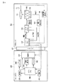
図1は、本発明の一実施形態に係る撮影装置の構成を示すブロック図である。ここで、図1に示す撮影装置は、レンズ交換式のデジタルカメラの例を示している。即ち、本撮影装置は、交換レンズ100と、カメラボディ200とを有している。交換レンズ100は、カメラボディ200に設けられたマウント201を介してカメラボディ200に着脱自在に構成されている。カメラボディ200に交換レンズ100が装着された際に、交換レンズ100内のレンズCPU107とカメラボディ200内のボディCPU208とが互いに通信自在に接続される。これにより、レンズCPU107はボディCPU208の制御に従って動作する。
Hereinafter, embodiments of the present invention will be described with reference to the drawings.
FIG. 1 is a block diagram showing a configuration of a photographing apparatus according to an embodiment of the present invention. Here, the photographing apparatus shown in FIG. 1 shows an example of a digital camera with interchangeable lenses. That is, the photographing apparatus includes the
以下、交換レンズ100、カメラボディ200のそれぞれについて説明する。
まず、交換レンズ100について説明する。図1に示すように、交換レンズ100は、フォーカスレンズ101と、ステッピングモータ102と、エンコーダ103と、信号検出回路104と、外部位置検出系105と、モータドライバ106と、レンズCPU107とを有している。
Hereinafter, each of the
First, the
フォーカスレンズ101は、図示しない被写体からの光束を集光するための撮影光学系に含まれるフォーカス調整のためのレンズである。このフォーカスレンズ101は、図示矢印で示す光軸方向に沿って駆動され、撮影光学系の焦点位置を調整する。
The
ステッピングモータ102は、モータドライバ106から1ステップ毎に入力されるパルス電流に従って所定のステップ角度ずつ回転駆動されるモータであって、フォーカスレンズ101を駆動するための可動部に取り付けられている。このステッピングモータ102を駆動させることによってフォーカスレンズ101をその光軸方向に沿って駆動させることが可能である。
The
図2(a)、図2(b)は、ステッピングモータ102を駆動するためのパルス入力の例を示す図である。ここで、図2(a)、図2(b)の例はステッピングモータ102の巻き線構成が2相(A相巻き線、B相巻き線)の場合を示している。
FIG. 2A and FIG. 2B are diagrams illustrating an example of pulse input for driving the stepping
図2(a)は2−2相駆動の場合のパルス入力を示しており、図2(b)は1−2相駆動の場合のパルス入力を示している。一般に、図2(b)に示す1−2相駆動では、図2(a)に示す2−2相駆動に比べて、ステッピングモータの回転量をより細かく制御できる。また、図2(b)においては、一点鎖線でマイクロステップ駆動の場合のパルス入力も示している。マイクロステップ駆動を行うことにより、さらに細かなステップでのステッピングモータの回転量の制御を行うことが可能である。本実施形態では、ステッピングモータ102の駆動手法は従来と同じ手法を用いることができる。ここでは、各駆動手法の詳細な説明については省略する。
2A shows the pulse input in the case of 2-2 phase driving, and FIG. 2B shows the pulse input in the case of 1-2 phase driving. In general, in the 1-2 phase driving shown in FIG. 2B, the rotation amount of the stepping motor can be controlled more finely than in the 2-2 phase driving shown in FIG. In FIG. 2B, pulse input in the case of microstep driving is also shown by a one-dot chain line. By performing microstep driving, it is possible to control the amount of rotation of the stepping motor in finer steps. In this embodiment, the same method as the conventional method can be used as the driving method of the stepping
図3は、1−2相駆動の場合のA相、/A(エーバー)相、B相、/B(ビーバー)相に対する励磁パターンとステッピングモータ102の回転方向との関係を示している。図3に示す順序に従ってA相、/A相、B相、/B相の励磁パターンを切り替える毎に、ステッピングモータ102は所定のステップ角度ずつ回転駆動する。
FIG. 3 shows the relationship between the excitation pattern for the A phase, / A (Aber) phase, B phase, and / B (Beaver) phase and the rotation direction of the stepping
エンコーダ103は、フォトインタラプタ(PI)と回転板とを有して構成されている。エンコーダ103のPIから出力されるPI信号より、フォーカスレンズ101の駆動量(駆動位置)を検出することが可能である。なお、エンコーダ103の詳細については後述する。
The
信号検出回路104は、エンコーダ103のPIから出力されるPI信号を2値化してレンズCPU107に出力する。このような構成により、レンズCPU107においてPI信号をデジタル処理可能となる。なお、レンズCPU107にA/D変換端子を設けておけば、PI信号をレンズCPU107において直接取り込むことも可能である。この場合、信号検出回路104は不要である。
The
外部位置検出系105は、エンコーダ103とは独立してフォーカスレンズ101の位置を検出する検出系であり、エンコーダ103で検出する位置間隔よりも大きい位置間隔を検出可能に構成されている。この外部位置検出系105からの位置検出信号もレンズCPU107に入力される。図4は、外部位置検出系105の構成例を示す図である。まず、図4(a)は、外部位置検出系105をメカ切片式エンコーダで構成する場合の例である。図4(a)の例においては、フォーカスレンズ101の駆動機構部に所定のエンコーダパターンを形成しておき、フォーカスレンズ101の移動に伴うエンコーダパターンとレンズCPU107の複数の入力端子との接触状態によって変化する信号FCENC1〜FCENC4を検出することでフォーカスレンズ101の位置検出を行う。また、図4(b)は、外部位置検出系105をリニアエンコーダで構成する場合の例である。図4(b)の例においては、フォーカスレンズ101の移動に伴い摺動する接点を可変抵抗器R1に接続しておき、フォーカスレンズ101の移動に伴って変化する可変抵抗器R1の分圧された電圧をレンズCPU107に設けたA/D変換器等で検出することで、フォーカスレンズ101の位置検出を行う。この他、各種の位置検出系を用いることが可能である。
The external
モータドライバ106は、レンズCPU107からの駆動指示信号を受けて、図2で示したような、ステッピングモータ102を回転駆動させるためのパルス電流をステップ単位で印加する。また、モータドライバ106は、ステッピングモータ102を回転駆動させるためのパルス電流を印加する際に、EXT信号をレンズCPU107に出力する。このEXT信号は、ステッピングモータ102の動作開始から動作終了までのタイミングをレンズCPU107に認識させるための信号である。
The
さらに、本実施形態におけるモータドライバ106は、1ステップ間隔でOKA信号をレンズCPU107に出力する。なお、図2及び図3に、OKA信号の出力タイミングを示している。OKA信号により、レンズCPU107は1ステップの区切りを認識する。なお、OKA信号の間隔はステッピングモータ102の駆動速度によって異なるものとなる。即ちステッピングモータ102を高速で駆動させる場合には、各巻き線の励磁パターンを高速で切り替える必要があるので、1ステップの間隔を短くする。したがって、OKA信号の間隔は短くなる。逆に、ステッピングモータ102を低速で駆動させる場合には、OKA信号の間隔は長くなる。
Furthermore, the
なお、1ステップに相当する時間は、フォーカスレンズ101の駆動に先だって決めることができる。このため予め決定した1ステップに対応した時間をレンズCPU107内でカウントするようにすれば、モータドライバ106から必ずしもOKA信号を出力させる必要はない。
Note that a time corresponding to one step can be determined prior to driving the
レンズCPU107は、ボディCPU208からのレンズ駆動指示を受けて、ステッピングモータ102の駆動方向、駆動量、駆動速度を指示するための駆動指示信号をモータドライバ106に出力する。また、本実施形態におけるレンズCPU107は制御部としての機能も有している。即ち、本実施形態におけるレンズCPU107は、エンコーダ103からのPI信号に従って、フォーカスレンズ101の駆動量を検出してモータドライバ106に与える駆動指示信号を制御する。さらに、本実施形態におけるレンズCPU107は、エンコーダ103からのPI信号及び外部位置検出系105からの位置検出信号に従って、ステッピングモータ102が正常動作しているか否かの判断も行う。
In response to the lens drive instruction from the
次に、カメラボディ200について説明する。図1に示すように、カメラボディ200は、撮像素子202と、シャッタ203と、手振れ補正部204と、表示部205と、ファインダ206と、電源207と、ボディCPU208とを有している。
Next, the
撮像素子202は、フォトダイオード等の光電変換素子が配列された受光面を有し、交換レンズ100内のフォーカスレンズ101を含む撮影光学系を介して受光面上に結像した図示しない被写体からの光を電気信号(以下、画像信号という)に変換し、さらにこの画像信号をデジタル信号(以下、画像データという)に変換してボディCPU208に出力する。
The
シャッタ203は、撮像素子202の受光面に対して配置され、ボディCPU208の指示に従って撮像素子202の受光面を露出状態又は遮光状態とする。撮像素子202の受光面の露出時間を制御することにより、撮像素子202における露出量を制御することが可能である。
The
手振れ補正部204は、カメラボディ200の揺れ等によって撮像素子202に発生する画像振れを、例えば撮像素子202をフォーカスレンズ101の光軸に垂直な平面内で移動させることによって補正する。
The camera
表示部205は、例えばカメラボディ200の背面に設けられ、ボディCPU208の制御に従って、撮像素子202を介して得られる画像データ等に基づく各種の画像を表示する。ファインダ206は、例えばカメラボディ200の背面に形成された窓部を介して被写体の状態を確認するためのものである。このファインダ206は、例えば電子ビューファインダであり、ボディCPU208の制御に従って、撮像素子202を介して得られる画像データに基づく画像がリアルタイムで表示されるようになされている。
The
電源207は、例えば2次電池等であり、カメラボディ200のボディCPU208等に電源電力を供給する。また、カメラボディ200に交換レンズ100が装着された際に、電源207は、交換レンズ100のレンズCPU107等にも電源電力を供給する。
The power source 207 is a secondary battery, for example, and supplies power to the
ボディCPU208は、撮像素子202、シャッタ203、手振れ補正部204、表示部205、ファインダ206等のカメラボディ200の各部の動作制御を行う。また、ボディCPU208は、撮像素子202を介して得られた画像データに対する画像処理等の各種のデータ処理も行う。さらに、オートフォーカス(AF)時等のフォーカスレンズ101を駆動させる必要がある場合に、ボディCPU208は、フォーカスレンズ101の駆動方向、駆動量、駆動速度を含む駆動指示信号をレンズCPU107に出力する。
The
次に、エンコーダ103の構成についてさらに説明する。図5は、エンコーダ103の詳細な構成を示す図である。図5において、エンコーダ103は、フォトインタラプタ(PI)1031と、遮光羽1032とを有している。
Next, the configuration of the
読取部としての機能を有するPI1031は、発光素子1031aと光検出素子1031bとが互いに対向するように形成されている。そして、PI1031は、発光素子1031aから照射された光が光検出素子1031bで受光された場合に、PI信号を信号検出回路104に出力するように構成されている。なお、発光素子1031aとしては例えば発光ダイオードを、光検出素子1031bとしては例えばフォトトランジスタを用いることができる。
The
回転体としての機能を有する遮光羽1032は、PI1031に形成された発光素子1031aと光検出素子1031bとの間に配置されるように、ステッピングモータ102の回転軸上に取り付けられている。さらに、遮光羽1032には図6(a)、図6(b)で示すような複数のスリット孔1032aが形成され、スリット孔1032a以外の部分が遮光部1032bとなっている。
The
本実施形態においては、幅の異なる複数種類のスリット孔1032aを形成する。各スリット孔1032aのそれぞれの幅は何れもステッピングモータ102の1ステップの駆動量に対応した幅の整数倍とする。また、図6(a)、図6(b)に示すように、遮光部1032bを挟んで隣接する幅が異なるスリット孔1032aを形成する。
In the present embodiment, a plurality of types of
なお、異なる種類のスリット孔1032aの幅の差は2ステップ以上とすることが望ましい。これは、PI信号の誤検出の可能性を低減するためである。
Note that the difference in width between the different types of
また、本実施形態においては、スリット孔1032aの幅と遮光部1032bの幅の合計の整数倍が、ステッピングモータ102の1回転分のステップ数となるように遮光部1032bの幅(即ち、スリット孔1032aの間隔)を決定する。この遮光部1032bの幅もスリット孔1032aと同様に1ステップの駆動量に対応した幅の整数倍とする。また、遮光部1032bの幅は全て等しくする。さらに、このように決定したスリット孔1032a及び遮光部1032bの幅に対し、外部位置検出系105の位置間隔は、スリット孔1032aの幅と遮光部1032bの幅との和の整数倍に対応した間隔よりも大きな間隔となるようにしておく。
Further, in the present embodiment, the width of the
図6(a)、図6(b)は、ステッピングモータ102の1回転分のステップ数を40ステップとした場合を例としている。
6A and 6B illustrate an example in which the number of steps for one rotation of the stepping
図6(a)は、3ステップの駆動量に対応した幅と9ステップの駆動量に対応した幅の2種類のスリット孔1032a、及び4ステップの駆動量に対応した幅の遮光部1032bで遮光羽1032を形成した例を示している。このようにスリット孔1032aを形成した場合、スリット孔1032aの幅と遮光部1032bの幅の合計は、4+3+4+9=20(ステップ)となる。この20ステップは2倍すればステッピングモータ102の1回転分のステップ数である40ステップとなる。
FIG. 6A shows light shielding by two types of
図6(b)は、2ステップの駆動量に対応した幅と5ステップの駆動量に対応した幅と7ステップの駆動量に対応した幅の3種類のスリット孔1032a、及び2ステップの駆動量に対応した幅の遮光部1032bで遮光羽1032を形成した例を示している。このようにスリット孔1032aを形成した場合、スリット孔1032aの幅と遮光部1032bの幅との和は、2+2+2+5+2+7=20(ステップ)となる。この場合もスリット孔1032aの幅と遮光部1032bの幅の合計を2倍すればステッピングモータ102の1回転分のステップ数である40ステップとなる。
FIG. 6B shows three types of
なお、図示はしていないが、例えば、4ステップの駆動量に対応した幅と8ステップの駆動量に対応した幅の2種類のスリット孔1032a、及び4ステップの駆動量に対応した幅の遮光部1032bで遮光羽1032を形成する等しても良い。この場合もスリット孔1032aの幅と遮光部1032bの幅の合計は、4+4+4+8=20(ステップ)となる。
Although not shown, for example, two types of
また、上述の例は何れも、スリット孔1032aの幅と遮光部1032bの幅との和を2倍してステッピングモータ102の1回転分のステップ数となる例を示している。しかしながら、スリット孔1032aの幅と遮光部1032bの幅との和が40(ステップ)、即ちスリット孔1032aの幅と遮光部1032bの幅との和の1倍となるようにスリット孔1032aを形成するようにしても良いし、スリット孔1032aの幅と遮光部1032bの幅との和が10(ステップ)、即ちスリット孔1032aの幅と遮光部1032bの幅との和の4倍となるようにスリット孔1032aを形成するようにしても良い。
In addition, each of the above examples shows an example in which the sum of the width of the
フォーカスレンズ101の駆動機構の可動部101aを駆動させるべく、ステッピングモータ102を回転駆動させると、この回転駆動に伴って遮光羽1032も回転する。遮光羽1032の回転状態により、PI1031の発光素子1031aから出射された光が、スリット孔1032aを介して光検出素子1031bで受光されるか、遮光部1032bによって遮光される。上述したように、光検出素子1031bで光が受光されている間はPI信号が出力されるので、PI信号が出力されている時間をカウントすることにより、遮光羽1032の回転方向及び回転量、即ちステッピングモータ102の駆動方向及び駆動量を検出することが可能である。
When the stepping
また、本実施形態では幅の異なる複数のスリット孔1032aを遮光羽1032に形成することにより、脱調等の異常検出を確実に行うことが可能である。この脱調検出の詳細については後述する。
In this embodiment, by forming a plurality of
以下、上述したような構成を有する撮影装置の動作について説明する。図7は、本実施形態に係る撮影装置におけるAF(オートフォーカス)時等で行われるレンズ駆動の際のメインの処理の流れについて示すフローチャートである。 Hereinafter, the operation of the photographing apparatus having the above-described configuration will be described. FIG. 7 is a flowchart showing the flow of main processing at the time of lens driving performed at the time of AF (autofocus) or the like in the photographing apparatus according to the present embodiment.
図7において、レンズCPU107は、ボディCPU208からレンズ駆動の指示がなされたか否かを判定する(ステップS101)。ステップS101の判定において、レンズ駆動指示がなされていない場合に、レンズCPU107は、脱調検出2の処理を行う(ステップS102)。なお、脱調検出2の処理の詳細については後述する。
In FIG. 7, the
脱調検出2の実行後、レンズCPU107は、脱調検出2の処理の結果、脱調が検出されたか否かを判定する(ステップS103)。ステップS103の判定において、脱調が検出されなかった場合には処理がステップS101に戻る。この場合に、レンズCPU107は、ボディCPU208からレンズ駆動の指示がなされたか否かを再び判定する。また、ステップS103の判定において、脱調が検出された場合に、レンズCPU107は、図7の処理を終了させる。この場合、脱調があった旨をボディCPU208に通知するようにしても良い。このようにすれば、例えばカメラボディ200の表示部205にレンズ駆動時に異常が生じた旨を表示させる等することが可能となる。
After the step-out
また、ステップS101の判定において、レンズ駆動指示がなされた場合に、レンズCPU107は、レンズ駆動を行う(ステップS104)。なお、レンズ駆動の処理の詳細については後述する。レンズ駆動の実行後、レンズCPU107は、ステップS103以後の処理を実行する。
In the determination in step S101, when a lens driving instruction is issued, the
図8は、脱調検出2の処理の詳細を示したフローチャートである。なお、この脱調検出2の処理中に、レンズCPU107にはエンコーダ103から信号検出回路104を介してPI信号が割り込み入力されるものとする。
FIG. 8 is a flowchart showing details of the process of step-out
図8において、レンズCPU107は、PI信号が入力されたか否かを判定する(ステップS201)。
In FIG. 8, the
ステップS201の判定において、PI信号が入力された場合に、レンズCPU107は、脱調検出2に対応した脱調判断を行う(ステップS202)。図7において示したように、脱調検出2は、ボディCPU208からレンズ駆動指示がなされていない場合に行われるものである。したがって、脱調検出2が行われる際には、通常は、フォーカスレンズ101が停止しており、PI信号の入力もないはずである。このため、ステップS201の判定において、PI信号が入力された場合に、レンズCPU107は、脱調が発生していると判断する。
When the PI signal is input in the determination in step S201, the
また、ステップS201の判定において、PI信号が入力されていない場合に、レンズCPU107は、図8の処理を終了させる。この場合には、図7のステップS103以後の処理が行われる。
If the PI signal is not input in the determination in step S201, the
図9は、レンズ駆動の処理の詳細を示したフローチャートである。なお、このレンズ駆動の処理中に、レンズCPU107には、エンコーダ103からのPI信号、外部位置検出系105からの外部位置検出信号、モータドライバ106からのOKA信号が割り込み入力されるものとする。
FIG. 9 is a flowchart showing details of the lens driving process. During the lens driving process, the
図9において、レンズCPU107は、フォーカスレンズ101を駆動させるために必要な初期設定を行う(ステップS301)。この初期設定においては、レンズ駆動指示とともに指示されたフォーカスレンズ101の駆動方向、駆動量、駆動速度に対応したステッピングモータ102の駆動方向、駆動量、駆動速度を算出するとともに、フォーカスレンズ101の駆動中におけるPI信号時間を算出する。
In FIG. 9, the
ここで、PI信号時間について説明する。PI信号時間は、PI信号が出力されるべき時間間隔である。このPI信号時間は、詳細は後述する脱調検出1の処理の際に用いられる。PI信号時間は、以下の式に従って算出する。
Here, the PI signal time will be described. The PI signal time is a time interval at which the PI signal should be output. This PI signal time is used in the processing of step-out
PI信号時間=(遮光羽1032に形成されたスリット孔の幅)×(OKA信号の間隔)
例えば、OKA信号の間隔をXとすると、図3(a)に示す遮光羽1032が取り付けられたステッピングモータ102の場合のPI信号時間は、スリット孔の幅が3ステップに対応している部分で3X、スリット孔の幅が9ステップに対応している部分で9Xとなる。この場合、ステッピングモータ102が一定速度で正常に駆動していれば、3X、9X、3X、9X、…、という順序でPI信号がH(ハイ)レベルとなる期間が表れることになる。なお、スリット孔部分がPI信号のH(ハイ)レベルに対応するものとする。
PI signal time = (width of slit hole formed in shading blade 1032) × (OKA signal interval)
For example, when the interval of the OKA signal is X, the PI signal time in the case of the stepping
初期設定の後、レンズCPU107は、内部の図示しないPI信号検出用のタイマのカウントを開始させる(ステップS302)。その後、レンズCPU107は、モータドライバ106に対して駆動指示信号を出力してフォーカスレンズ101の駆動を開始させる(ステップS303)。さらに、レンズCPU107は、信号検出回路104からのPI信号の検出を開始する(ステップS304)。
After the initial setting, the
次に、レンズCPU107は、信号検出回路104からのPI信号が有効であるか無効であるかの判定を行う(ステップS305)。
Next, the
ここで、PI信号有効/無効判定の処理について図10〜図12を参照して説明する。図10は、PI信号有効/無効判定の処理について示すフローチャートである。 Here, PI signal valid / invalid determination processing will be described with reference to FIGS. FIG. 10 is a flowchart showing the PI signal valid / invalid determination process.
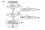
図10において、レンズCPU107は、モータドライバ106からOKA信号が入力されたか否かを判定する(ステップS401)。ステップS401の判定において、OKA信号が入力された場合には、PI信号のカウントを0にクリアする(ステップS402)。
In FIG. 10, the
ステップS401又はS402の後、レンズCPU107は、信号検出回路104からPI信号が入力されたか否かを判定する(ステップS403)。本実施形態においては、OKA信号によって区切られる区間(OKA信号区間)内における、PI信号の立ち上がり、立ち下がりをそれぞれ1カウントとし、PI信号の立ち上がり又は立ち下がりがあった場合にはPI信号が入力されたと判定する。ステップS403の判定において、PI信号が入力された場合には、PI信号のカウントに1を加算する(ステップS404)。
After step S401 or S402, the
ステップS403又はS404の後、レンズCPU107は、OKA信号区間内でのPI信号のカウント結果から、入力されたPI信号が有効であるか無効であるかを判定する(ステップS405)。本実施形態においては、OKA信号区間内でのPI信号の立ち上がり、立ち下がりの合計が偶数の場合にはPI信号が無効であると判定する。逆に、OKA信号区間内でのPI信号の立ち上がり、立ち下がりの合計が奇数の場合にはPI信号が有効であると判定する。
After step S403 or S404, the
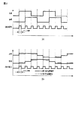
図11(a)、図11(b)は、PI信号が無効となる場合の例を示している。図11(a)は、OKA信号区間中に、1つの立ち上がりと1つの立ち下がりが検出された例(PI信号の立ち上がり、立ち下がりの合計が2の場合)を示している。また、図11(b)は、OKA信号区間中に、2つの立ち上がりと2つの立ち下がりが検出された例(PI信号の立ち上がり、立ち下がりの合計が4の場合)を示している。OKA信号区間中にPI信号の立ち上がりと立ち下がりの両方が検出されるのは、ステッピングモータ102の1ステップ分の動作に対応して、遮光羽1032の遮光部1032b、スリット孔1032a、遮光部1032bがそれぞれ検出される場合、若しくは遮光羽1032のスリット孔1032a、遮光部1032b、スリット孔1032aがそれぞれ検出される場合である。このような場合は、OKA信号区間の終了時点でステッピングモータ102が本来駆動すべき回転方向に対して逆回転している、即ちステッピングモータ102が振動的に動作していると考えられる。したがって、このような場合のPI信号は無効であるとする。
FIG. 11A and FIG. 11B show examples in which the PI signal is invalid. FIG. 11A shows an example in which one rising edge and one falling edge are detected during the OKA signal interval (when the sum of the rising edge and falling edge of the PI signal is 2). FIG. 11B shows an example in which two rising edges and two falling edges are detected during the OKA signal interval (when the total rise and fall of the PI signal is 4). Both rising and falling of the PI signal are detected during the OKA signal period, corresponding to the operation of the stepping
図12(a)、図12(b)は、PI信号が有効となる場合の例を示している。図12(a)は、OKA信号区間中に、2つの立ち上がりと1つの立ち下がりが検出された例(PI信号の立ち上がり、立ち下がりの合計が3の場合)を示している。また、図12(b)は、OKA信号区間中に、3つの立ち上がりと2つの立ち下がりが検出された例(PI信号の立ち上がり、立ち下がりの合計が5の場合)を示している。このような場合には、OKA信号区間の終了時点で最終的に回転するべき方向に正しくステッピングモータ102が回転駆動している。したがって、このような場合のPI信号は有効であるとする。
FIGS. 12A and 12B show an example in which the PI signal is valid. FIG. 12A shows an example in which two rising edges and one falling edge are detected during the OKA signal interval (when the sum of the rising edge and falling edge of the PI signal is 3). FIG. 12B shows an example in which three rising edges and two falling edges are detected during the OKA signal interval (when the total rise and fall of the PI signal is 5). In such a case, the stepping
ここで、図9に戻って説明を続ける。ステップS305のPI信号有効/無効判定の後、PI信号検出用のタイマのカウントから、有効であると判定したPI信号がHとなっている期間を算出する(ステップS306)。次に、レンズCPU107は、現在、脱調検出期間であるか否かを判定する(ステップS307)。本実施形態における脱調検出期間は、ステッピングモータ102が一定速度で動作している期間(脱調検出有効期間1)若しくはステッピングモータ102が停止している期間(脱調検出有効期間2)の何れかとする。実際には、ステップS307の判定は、レンズ駆動中に行われるものであるので、ステップS307においては、脱調検出有効期間1であるか否かを判定することになる。また、脱調検出有効期間2における脱調判断は、上述した脱調検出2の処理が該当する。なお、図13に、ステッピングモータ102の状態と脱調検出有効期間1、2との関係を示す。図13に示すように、初期励磁(ステッピングモータ102の駆動前の励磁)、保持励磁(ステッピングモータ102の駆動後の励磁)は脱調検出を行わない。また、初期励磁後のステッピングモータ102の加速中や保持励磁前のステッピングモータ102の減速中も脱調検出を行わない。さらに、保持励磁後の所定時間A(ステッピングモータ102の機械的な構造によって決まる値)msの間も脱調検出を行わない。初期励磁の期間、保持励磁の期間、ステッピングモータ102の加速中やステッピングモータ102の減速中、保持励磁後の所定時間Aの期間は、何れもステッピングモータ102の動作が安定していない期間である。そして、これら以外の期間においては脱調判断を行うようにする。
Here, returning to FIG. 9, the description will be continued. After the PI signal valid / invalid determination in step S305, the period during which the PI signal determined to be valid is H is calculated from the count of the PI signal detection timer (step S306). Next, the
ステップS307の判定において、現在、脱調検出有効期間1である場合に、レンズCPU107は、脱調検出有効期間1に対応した脱調判断を行う(ステップS308)。
If it is determined in step S307 that the current step-out detection valid period is 1, the
ここで、脱調検出有効期間1に対応した脱調判断について説明する。本実施形態においては、脱調検出有効期間1中に、以下の3つの条件から脱調等の異常が発生しているか否かを判断する。
(1) 同じ出力パターンのPI信号が連続しているか
(2) PI信号がHレベルである時間がPI信号期間と一致しているか
(3) 外部位置検出系105からの外部位置検出信号の状態
まず、(1)について説明する。本実施形態における遮光羽1032は、図6(a)、図6(b)に示したように、遮光部1032bを挟んで異なる幅のスリット孔1032aが隣接するように、スリット孔1032aが形成されている。したがって、例えば図6(a)に示すようなスリット孔1032aが形成された遮光羽1032が取り付けられたステッピングモータ102をある方向に一定速で正常に駆動させたとすると、PI1031から出力されるPI信号のハイ(H)/ロー(L)の関係は図14(a)で示したものとなる。即ち、ステッピングモータ102が正常に駆動していれば、異なる幅のスリット孔1032aに対応したPI信号が交互に入力されるはずである。このような考え方に基づき、例えば2回連続して同じ幅のスリット孔1032aに対応したPI信号が入力されてくるような状態では、何らかの外乱によってステッピングモータ102自体が停止していたり、或いはステッピングモータ102が振動的な動作をしたりしているとして、脱調であると判定する。
Here, the step-out determination corresponding to the step-out detection
(1) Is PI signal of the same output pattern continuous?
(2) Whether the time during which the PI signal is at the H level coincides with the PI signal period
(3) State of External Position Detection Signal from External
次に、(2)について説明する。上述したように、PI信号がHとなる期間は、スリット孔1032aの幅とOKA信号の間隔とによって決まるものである。したがって、PI信号がHである期間がレンズ駆動初期設定の際に算出したPI信号期間と一致していない場合には、脱調であると判定する。実際には、レンズ駆動初期設定の際に算出したPI信号期間に図14(b)で示すような許容誤差Y(%)の時間幅を設定することが望ましい。
Next, (2) will be described. As described above, the period during which the PI signal is H is determined by the width of the
次に、(3)について説明する。PI信号が正常に出力されていても、必ずしも脱調が起こっていないとは言えない。このため、PI信号が入力され、そのPI信号の入力からは外部位置検出系105からも外部位置検出信号が入力されるくらいのステッピングモータ102の駆動量が算出されているにも関らず、外部位置検出系105から外部位置検出信号が入力されていない場合にも、脱調であると判定する。例えば、図14(c)に示す外部位置検出系105の信号間隔(矢印内)にて、予定されるPI信号入力数と、実際に検出されたPI信号入力数とを比較し、その差が所定量を超える場合に脱調と判定する。
Next, (3) will be described. Even if the PI signal is output normally, it cannot be said that the step-out has not necessarily occurred. For this reason, although the PI signal is input and the driving amount of the stepping
以上のような脱調判断を用いることで、最低速度から最高速度までの様々な速度領域でステッピングモータを定速駆動する場合であっても正しく脱調判断を行うことができる。また、低速度側では、ステッピングモータ102が振動的な動作となった場合に、その状態も脱調として検出することが可能である。
By using the step-out determination as described above, the step-out determination can be correctly performed even when the stepping motor is driven at a constant speed in various speed ranges from the lowest speed to the highest speed. On the low speed side, when the stepping
ステップS308の脱調検出有効期間1に対応した脱調判断の後、レンズCPU107は、脱調が検出されたか否かを判定する(ステップS309)。ステップS309の判定において、脱調が検出されなかった場合には処理がステップS303に戻る。そして、レンズCPU107は、フォーカスレンズ101の駆動量が、ボディCPU208から指示された駆動量に達するまでステップS303〜ステップS309の処理を繰り返す。一方、ステップS309の判定において、脱調が検出された場合に、レンズCPU107は、図9の処理を終了させる。この場合、脱調があった旨をボディCPU208に通知するようにしても良い。このようにすれば、例えばカメラボディ200の表示部205にレンズ駆動時に異常が生じた旨を表示させる等することが可能となる。
After step out determination corresponding to step out detection
以上説明したように、本実施形態によれば、遮光羽1032に幅の異なる複数種類のスリット孔1032aを形成することにより、レンズCPU107に入力されるPI信号がHとなる期間に所定の関係を持たせるようにしている。これにより、撮影装置の可動部を駆動するのに好適なステッピングモータ102における脱調を正しく判断することが可能である。
As described above, according to the present embodiment, a plurality of types of
以上実施形態に基づいて本発明を説明したが、本発明は上述した実施形態に限定されるものではなく、本発明の要旨の範囲内で種々の変形や応用が可能なことは勿論である。上述した例では、ステッピングモータ102が駆動する撮影装置の可動部の例としてフォーカスレンズ101の可動部を例示している。しかしながら、本実施形態の技術は、この他の各種の可動部に対しても適用可能である。例えば絞りを駆動するためのステッピングモータに対して本実施形態の技術を適用しても良いし、撮影光学系がズームレンズを有するような構成の場合には、ズームレンズを駆動するためのステッピングモータに対して本実施形態の技術を適用しても良い。
Although the present invention has been described above based on the embodiments, the present invention is not limited to the above-described embodiments, and various modifications and applications are naturally possible within the scope of the gist of the present invention. In the above-described example, the movable part of the
さらに、上記した実施形態には種々の段階の発明が含まれており、開示される複数の構成要件の適当な組合せにより種々の発明が抽出され得る。例えば、実施形態に示される全構成要件からいくつかの構成要件が削除されても、上述したような課題を解決でき、上述したような効果が得られる場合には、この構成要件が削除された構成も発明として抽出され得る。 Further, the above-described embodiments include various stages of the invention, and various inventions can be extracted by appropriately combining a plurality of disclosed constituent elements. For example, even if some configuration requirements are deleted from all the configuration requirements shown in the embodiment, the above-described problem can be solved, and this configuration requirement is deleted when the above-described effects can be obtained. The configuration can also be extracted as an invention.
100…交換レンズ、101…フォーカスレンズ、102…ステッピングモータ、103…エンコーダ、104…信号検出回路、105…外部位置検出系、106…モータドライバ、107…レンズCPU、200…カメラボディ、201…マウント、202…撮像素子、203…シャッタ、204…補正部、205…表示部、206…ファインダ、207…電源、208…ボディCPU、1031…フォトインタラプタ(PI)、1032…遮光羽
DESCRIPTION OF
Claims (4)
上記ステッピングモータの上記1ステップの駆動量に対応する幅を1単位とし、該1単位の整数倍の幅を有するスリット孔であって、2種類以上の異なる幅のスリット孔が形成され、上記ステッピングモータの回転駆動に伴って回転する回転体と、
上記スリット孔の有無を読み取って、該スリット孔の有無を示す信号を出力する読取部と、
上記読取部からの上記スリット孔の有無を示す信号の期間を検出し、該期間に基づいて、上記ステッピングモータが正常動作しているか否かを判断する制御部と、
を具備し、
上記スリット孔の幅と上記スリット孔の間隔の合計の整数倍は、上記ステッピングモータの1回転のステップ数と一致していることを特徴とする撮影装置。 A stepping motor that is rotationally driven in accordance with a pulse signal input in units of one step, and that drives the movable portion of the imaging apparatus by the rotational drive;
The stepping motor has a width corresponding to the driving amount of one step as one unit, and is a slit hole having a width that is an integral multiple of the one unit, and two or more types of slit holes having different widths are formed. A rotating body that rotates with the rotation of the motor;
A reading unit that reads the presence or absence of the slit hole and outputs a signal indicating the presence or absence of the slit hole;
A control unit that detects a period of a signal indicating the presence or absence of the slit hole from the reading unit and determines whether or not the stepping motor is operating normally based on the period;
Equipped with,
The imaging apparatus according to claim 1, wherein an integral multiple of the total width of the slit holes and the interval between the slit holes is equal to the number of steps of one rotation of the stepping motor .
Priority Applications (1)
| Application Number | Priority Date | Filing Date | Title |
|---|---|---|---|
| JP2009130380A JP5430231B2 (en) | 2009-05-29 | 2009-05-29 | Imaging device |
Applications Claiming Priority (1)
| Application Number | Priority Date | Filing Date | Title |
|---|---|---|---|
| JP2009130380A JP5430231B2 (en) | 2009-05-29 | 2009-05-29 | Imaging device |
Publications (3)
| Publication Number | Publication Date |
|---|---|
| JP2010279197A JP2010279197A (en) | 2010-12-09 |
| JP2010279197A5 JP2010279197A5 (en) | 2012-06-28 |
| JP5430231B2 true JP5430231B2 (en) | 2014-02-26 |
Family
ID=43425622
Family Applications (1)
| Application Number | Title | Priority Date | Filing Date |
|---|---|---|---|
| JP2009130380A Active JP5430231B2 (en) | 2009-05-29 | 2009-05-29 | Imaging device |
Country Status (1)
| Country | Link |
|---|---|
| JP (1) | JP5430231B2 (en) |
Family Cites Families (2)
| Publication number | Priority date | Publication date | Assignee | Title |
|---|---|---|---|---|
| JPS6056074B2 (en) * | 1981-05-25 | 1985-12-07 | 株式会社デンソー | Reference position detection method for pulse motor |
| JPH03183399A (en) * | 1989-12-13 | 1991-08-09 | Hitachi Ltd | Pulse motor drive |
-
2009
- 2009-05-29 JP JP2009130380A patent/JP5430231B2/en active Active
Also Published As
| Publication number | Publication date |
|---|---|
| JP2010279197A (en) | 2010-12-09 |
Similar Documents
| Publication | Publication Date | Title |
|---|---|---|
| US7885529B2 (en) | Lens driving apparatus, imaging apparatus, and lens barrel and camera main body used for this | |
| JP6347582B2 (en) | Rotation detection device, motor control device, motor driven device, correction method and correction program for rotation detection device | |
| JP5004830B2 (en) | Lens driving device, lens barrel and optical instrument | |
| US20140176037A1 (en) | Control unit of actuator | |
| JP4886503B2 (en) | Lens barrel | |
| JP2009162881A (en) | Lens position control apparatus and its control method | |
| KR101413097B1 (en) | Drive control apparatus, image pickup apparatus, and drive control method | |
| JP5430231B2 (en) | Imaging device | |
| JP2010243900A (en) | Lens driving device and lens barrel having the same | |
| JP5769979B2 (en) | Camera or camera system having backlash correction function | |
| JP5084523B2 (en) | POSITION DETECTION DEVICE, IMAGING DEVICE, AND OPTICAL DEVICE | |
| JP2021018278A (en) | Optical device, imaging apparatus, and driving method of optical device | |
| JP2020024299A (en) | Optical apparatus | |
| JP5911216B2 (en) | Optical apparatus and control method thereof | |
| JP7328422B2 (en) | LENS DEVICE AND IMAGING DEVICE HAVING OPERATION RING | |
| JP7150506B2 (en) | LENS DEVICE HAVING OPERATION RING, IMAGING DEVICE, AND LENS DEVICE CONTROL METHOD AND PROGRAM | |
| JP4552778B2 (en) | Positioning device, shake correction device, and imaging device | |
| JPH07218961A (en) | Lens driving system for camera provided with shake-proof function | |
| JP2024066229A (en) | Optical control device and optical control method thereof | |
| JP2017003403A (en) | Encoder signal processing device and device using encoder | |
| JP2013179792A (en) | Optical instrument | |
| JP6494271B2 (en) | Stepping motor control device, optical apparatus, stepping motor control method, program, and storage medium | |
| JP2015130749A (en) | Interchangeable lens, imaging apparatus, and method for controlling interchangeable lens | |
| JP2020013029A (en) | Lens device having operation ring and imaging device | |
| JP2010243957A (en) | Optical equipment |
Legal Events
| Date | Code | Title | Description |
|---|---|---|---|
| A521 | Request for written amendment filed |
Free format text: JAPANESE INTERMEDIATE CODE: A523 Effective date: 20120515 |
|
| A621 | Written request for application examination |
Free format text: JAPANESE INTERMEDIATE CODE: A621 Effective date: 20120515 |
|
| A977 | Report on retrieval |
Free format text: JAPANESE INTERMEDIATE CODE: A971007 Effective date: 20130821 |
|
| A131 | Notification of reasons for refusal |
Free format text: JAPANESE INTERMEDIATE CODE: A131 Effective date: 20130827 |
|
| A521 | Request for written amendment filed |
Free format text: JAPANESE INTERMEDIATE CODE: A523 Effective date: 20131025 |
|
| TRDD | Decision of grant or rejection written | ||
| A01 | Written decision to grant a patent or to grant a registration (utility model) |
Free format text: JAPANESE INTERMEDIATE CODE: A01 Effective date: 20131112 |
|
| A61 | First payment of annual fees (during grant procedure) |
Free format text: JAPANESE INTERMEDIATE CODE: A61 Effective date: 20131203 |
|
| R151 | Written notification of patent or utility model registration |
Ref document number: 5430231 Country of ref document: JP Free format text: JAPANESE INTERMEDIATE CODE: R151 |
|
| S111 | Request for change of ownership or part of ownership |
Free format text: JAPANESE INTERMEDIATE CODE: R313111 |
|
| R350 | Written notification of registration of transfer |
Free format text: JAPANESE INTERMEDIATE CODE: R350 |
|
| S531 | Written request for registration of change of domicile |
Free format text: JAPANESE INTERMEDIATE CODE: R313531 |
|
| R350 | Written notification of registration of transfer |
Free format text: JAPANESE INTERMEDIATE CODE: R350 |
|
| R250 | Receipt of annual fees |
Free format text: JAPANESE INTERMEDIATE CODE: R250 |
|
| R250 | Receipt of annual fees |
Free format text: JAPANESE INTERMEDIATE CODE: R250 |
|
| R250 | Receipt of annual fees |
Free format text: JAPANESE INTERMEDIATE CODE: R250 |
|
| S111 | Request for change of ownership or part of ownership |
Free format text: JAPANESE INTERMEDIATE CODE: R313113 |
|
| R350 | Written notification of registration of transfer |
Free format text: JAPANESE INTERMEDIATE CODE: R350 |
|
| R250 | Receipt of annual fees |
Free format text: JAPANESE INTERMEDIATE CODE: R250 |
|
| R250 | Receipt of annual fees |
Free format text: JAPANESE INTERMEDIATE CODE: R250 |
|
| R250 | Receipt of annual fees |
Free format text: JAPANESE INTERMEDIATE CODE: R250 |