JP5427716B2 - Staggered head stitch shift in continuous feed direct marking printer - Google Patents
Staggered head stitch shift in continuous feed direct marking printer Download PDFInfo
- Publication number
- JP5427716B2 JP5427716B2 JP2010161189A JP2010161189A JP5427716B2 JP 5427716 B2 JP5427716 B2 JP 5427716B2 JP 2010161189 A JP2010161189 A JP 2010161189A JP 2010161189 A JP2010161189 A JP 2010161189A JP 5427716 B2 JP5427716 B2 JP 5427716B2
- Authority
- JP
- Japan
- Prior art keywords
- printhead
- array
- print head
- arrays
- stitch
- Prior art date
- Legal status (The legal status is an assumption and is not a legal conclusion. Google has not performed a legal analysis and makes no representation as to the accuracy of the status listed.)
- Expired - Fee Related
Links
Images


Classifications
-
- B—PERFORMING OPERATIONS; TRANSPORTING
- B41—PRINTING; LINING MACHINES; TYPEWRITERS; STAMPS
- B41J—TYPEWRITERS; SELECTIVE PRINTING MECHANISMS, i.e. MECHANISMS PRINTING OTHERWISE THAN FROM A FORME; CORRECTION OF TYPOGRAPHICAL ERRORS
- B41J2/00—Typewriters or selective printing mechanisms characterised by the printing or marking process for which they are designed
- B41J2/005—Typewriters or selective printing mechanisms characterised by the printing or marking process for which they are designed characterised by bringing liquid or particles selectively into contact with a printing material
- B41J2/01—Ink jet
- B41J2/135—Nozzles
- B41J2/145—Arrangement thereof
Landscapes
- Ink Jet (AREA)
- Particle Formation And Scattering Control In Inkjet Printers (AREA)
Description
本開示は一般に複数のプリントヘッドアレイを有する作像装置に関し、特にそのような作像装置における複数のプリントヘッドアレイの配置に関する。 The present disclosure relates generally to imaging devices having a plurality of printhead arrays, and more particularly to the placement of a plurality of printhead arrays in such imaging devices.
インク印刷装置には単一のプリントヘッドを使用するものもあるが、多くのインク印刷装置は印刷速度を上げるために複数のプリントヘッドを使用する。例えば、いくつかの装置では複数のプリントヘッドアレイを使用し、この複数のプリントヘッドアレイの各アレイは画像受信面を横切るように端から端まで配置された複数のプリントヘッドを有する。アレイのプリントヘッド端はステッチラインまたはステッチジョイントと呼ばれる位置で一列に配置される。液滴量、液滴位置およびその他属性等、プリントヘッドの印刷特性がステッチラインのどちらかの側において異なると、プリントヘッド間に目に見えるステッチライン不良が生じる。ステッチライン不良は、ステッチジョイントにおける特定ラインの不良、またはプリントヘッド間の密度のばらつきとして現れる場合がある。いずれの場合も、ステッチライン不良は印刷媒体上で処理方向に延伸するバンディングとして知られる画質の不具合を引き起こす場合がある。プリントヘッドアレイのプリントヘッド間でステッチライン不良を補正またはマスキングする方法が開発されてきた。複数のプリントヘッドアレイを利用して画像受信面に画像を生成する既知のプリントヘッドシステムでは、複数のプリントヘッドのステッチラインは一列に配置されている。複数のプリントヘッドアレイのステッチラインを一列に配置すると、異なるプリントヘッドアレイのステッチライン不良が一体化してさらに目立つ場合がある。 Some ink printing devices use a single printhead, but many ink printing devices use multiple printheads to increase printing speed. For example, some devices use a plurality of printhead arrays, each array of the plurality of printhead arrays having a plurality of printheads disposed end to end across the image receiving surface. The printhead ends of the array are arranged in a row at locations called stitch lines or stitch joints. If the print characteristics of the print head, such as drop volume, drop position and other attributes, differ on either side of the stitch line, a visible stitch line defect occurs between the print heads. Stitch line defects may appear as defects in specific lines at stitch joints or density variations between printheads. In any case, stitch line defects can cause image quality defects known as banding that extends in the processing direction on the print medium. Methods have been developed to correct or mask stitch line defects between printheads in a printhead array. In a known printhead system that uses a plurality of printhead arrays to generate an image on the image receiving surface, the stitch lines of the plurality of printheads are arranged in a line. When stitch lines of a plurality of print head arrays are arranged in a row, stitch line defects of different print head arrays may be integrated and become more conspicuous.
本発明の目的は、複数のプリントヘッドアレイシステムにおいて、ステッチライン不良の蓄積を阻止または制限するプリントヘッドアレイの配置を提供することである。 It is an object of the present invention to provide a printhead array arrangement that prevents or limits the accumulation of stitch line defects in a plurality of printhead array systems.
本開示は、複数のプリントヘッドアレイシステムにおいて、ステッチライン不良の蓄積を阻止または制限するプリントヘッドアレイの配置を提供する。具体的には、1つの実施形態において、作像装置は作像装置において処理方向に移動するように構成された画像受信面を含んでいる。複数のプリントヘッドアレイはマーキング材を前記画像受信面上に付着させるよう配置されている。各プリントヘッドアレイは前記画像受信面を横切るように処理方向と直交する方向に配列された複数のプリントヘッドを備える。各プリントヘッドアレイは、前記処理方向と直交する方向と平行な軸に沿った位置に対応する少なくとも1つのステッチラインを含み、前記位置では前記プリントヘッドアレイの1つのプリントヘッドの端部が、プリントヘッドアレイの別のプリントヘッドの端部と実質的に一列に並んでいる。各プリントヘッドアレイの前記少なくとも1つのステッチラインは、前記他のプリントヘッドアレイの各々の前記少なくとも1つのステッチラインから前記処理方向と直交する方向に所定距離だけオフセットされている。 The present disclosure provides a printhead array arrangement that prevents or limits the accumulation of stitch line defects in multiple printhead array systems. Specifically, in one embodiment, the imaging device includes an image receiving surface configured to move in the processing direction in the imaging device. The plurality of print head arrays are arranged to deposit a marking material on the image receiving surface. Each print head array includes a plurality of print heads arranged in a direction orthogonal to the processing direction so as to cross the image receiving surface. Each printhead array includes at least one stitch line corresponding to a position along an axis parallel to a direction orthogonal to the processing direction, at which the end of one printhead of the printhead array is printed It is substantially aligned with the end of another printhead in the head array. The at least one stitch line of each print head array is offset from the at least one stitch line of each of the other print head arrays by a predetermined distance in a direction perpendicular to the processing direction.
この実施形態についての一般的な理解を得るために、図面を参照するものとする。
図面全体において、同様の構成要素には同様の参照番号を使用している。
To obtain a general understanding of this embodiment, reference is made to the drawings.
Like reference numerals have been used for like components throughout the drawings.
ここで言う「プリンタ」または「作像装置」とは、一般に画像を付着させて印刷媒体に印刷する装置を意味し、デジタルコピー機、製本機械、ファクシミリ装置、マルチファンクション機など、任意の目的で印刷物を出力する機能を実行する装置を包含してもよい。「記録媒体」とは、物理的な用紙、プラスチックシートまたは画像用の他の好適な物理的印刷媒体基材であってもよく、単票でも巻き取り形態のものであってもよい。「印刷ジョブ」または「ドキュメント」とは、標準的には1セットの関連するシートであり、通常特定のユーザあるいはその他関係者が供給する1セットのオリジナル印刷ジョブシートまたは電子ドキュメントページ画像からコピーされた1枚以上の照合コピーセットである。画像は、一般にマーキングエンジンによって印刷媒体上にレンダリングされる電子フォーム情報から成り、テキスト、グラフィックス、写真などを含んでいてもよい。ここで言う処理方向とは、画像が転写される基材が作像装置内を移動する方向である。処理方向と直交する方向とは、基材と同一の平面に沿った方向であり、処理方向に対して実質的に垂直である。 The term “printer” or “imaging device” as used herein generally refers to a device that attaches an image and prints it on a print medium. For any purpose, such as a digital copier, a bookbinding machine, a facsimile machine, or a multi-function machine. You may include the apparatus which performs the function to output printed matter. The “recording medium” may be a physical paper, a plastic sheet or other suitable physical printing medium substrate for images, and may be a single sheet or a wound form. A “print job” or “document” is typically a set of related sheets, usually copied from a set of original print job sheets or electronic document page images supplied by a particular user or other party. One or more collation copy sets. An image typically consists of electronic form information rendered on a print medium by a marking engine and may include text, graphics, photographs, and the like. The processing direction referred to here is a direction in which the base material to which the image is transferred moves in the image forming apparatus. The direction orthogonal to the processing direction is a direction along the same plane as the substrate, and is substantially perpendicular to the processing direction.
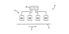
図1は、作像装置10の実施形態の正面略図である。図1に示すように、作像装置10は画像受信面上にマーキング材を付着させて画像を形成するプリントヘッドシステム18の正面で処理方向Pに向かって搬送される画像受信面14を含んでいる。1つの実施形態では、作像装置はダイレクトマーキング作像装置であり、この装置の画像受信面は、プリントヘッドシステムによって画像が直接形成される「基材」(紙、プラスチックまたは他の印刷可能な材料)から成る非常に長い(つまり実質的に連続する)巻き取り紙Wにより構成される。あるいは、作像装置は画像受信面がベルトまたはドラム型の中間転写面により構成された間接的なマーキング装置であってもよく、この中間転写面に画像を形成した後、巻き取り紙または媒体シートのような最終受信基材に画像を転写してもよい。画像受信面は直線的でも湾曲していてもよく、水平、垂直、または水平と垂直の組み合わせを含む任意の適切なパスを有してもよく、任意の適切な方法でプリントヘッドシステムにより処理方向に搬送してもよい。さらに、作像装置はシングルパスまたはマルチパス印刷プロセスを採用してもよい。シングルパス印刷プロセスでは、画像はプリントヘッドシステムを通過した画像受信面の単一通路にて画像受信面上に形成される。マルチパス印刷プロセスでは、画像はプリントヘッドシステムを通過した画像受信面の複数の通路にて画像受信面上に構築される。例えば、図1の画像受信面を、プリントヘッドシステムの前で回転するよう構成したベルトまたはドラムにより構成してもよい。
FIG. 1 is a schematic front view of an embodiment of an
プリントヘッドシステム18は一連のプリントヘッドアレイ24A〜Dを備え、各プリントヘッドアレイは処理方向と直交する方向、つまり(以下で詳細に説明する)処理方向に実質的に垂直な方向に画像受信面の幅方向にわたって配列された複数のプリントヘッドを含んでいる。プリントヘッドはそれぞれ巻き取り紙上にインクを射出する複数のインクジェットを備える。プリントヘッドアレイのプリントヘッドはそれぞれ、単一の固定バーまたは位置決め装置に取り付けられた完全に個別のユニットであってもよい。あるいは、プリントヘッドアレイのプリントヘッドは、例えばフラットなバッカバー上に配置されたシリコンダイスなど、同じように使用および/または製造されるインクジェットエゼクタ群により構成してもよい。
The printhead system 18 comprises a series of
簡略化のため、図1には各プリントヘッドアレイが1色のインクを画像受信面上に付着させるよう構成された4つのプリントヘッドアレイを示しているが、プリントヘッドアレイの個数は適切であれば、何個であってもよい。以下に説明するように、複数のプリントヘッドアレイを設けて、作像装置で使用する各カラーまたは色合いのインクを提供してもよい。一般に知られているように、異なるプリントヘッドアレイによって形成された異なるカラーの画像を画像受信面上のオーバーラップ領域に配置することにより、プリントコントローラ20から各プリントヘッドアレイに画像パス22を通って送られた画像データに基づいてマルチカラー画像を形成する。
For simplicity, FIG. 1 shows four printhead arrays in which each printhead array is configured to deposit one color of ink on the image receiving surface, although the number of printhead arrays is appropriate. Any number may be used. As described below, a plurality of printhead arrays may be provided to provide each color or shade of ink for use in the imaging device. As is generally known, by placing different color images formed by different printhead arrays in overlapping areas on the image receiving surface, the
1つの実施形態では、作像装置10で使用するインクは「相変化インク」であり、これはインクが室温では実質的に固体であり、作像受信面上への吐出のために相変化インク融解温度まで加熱すると実質的に液体となることを意味する。相変化インク融解温度は、固相のインクを液体または融解状態へ融解可能な温度であれば何度であってもよい。1つの実施形態では、相変化インク融解温度は約100℃から140℃である。しかしながら別の実施形態では、例えばトナー、水性インク、油性インク、紫外線硬化型インクなど、適切であればどのようなマーキング材またはインクを使用してもよい。
In one embodiment, the ink used in
次に図2にプリントヘッドアレイの実施形態を示す。プリントヘッドアレイは、実質的に処理方向と直交する方向CPに画像受信面14(図2において図示せず)の幅方向を横切るように端から端まで配列された複数のプリントヘッドを備える。図2の実施形態では、プリントヘッドアレイ24はそれぞれ4つのプリントヘッドを備えるが、プリントヘッドアレイが有するプリントヘッド数はそれ以上でもそれ以下でもよい。プリントヘッドアレイのプリントヘッド32、34、36および38はそれぞれ対応する前方表面を有し、この前方表面を通して融解した相変化インクなどのマーキング材を受信面14上に射出して画像を形成することができる。
Next, FIG. 2 shows an embodiment of a print head array. The print head array includes a plurality of print heads arranged from end to end so as to cross the width direction of the image receiving surface 14 (not shown in FIG. 2) in a direction CP substantially perpendicular to the processing direction. In the embodiment of FIG. 2, each
図2の実施形態では、プリントヘッドアレイ24は千鳥配置された全幅アレイ(SFWA)を備える。SFWAは2列に配置された4つのプリントヘッド28、30、32、34を備え、各列が2つのプリントヘッドを有する。SFWAにおけるプリントヘッド列はそれぞれ、画像受信面パスの処理方向Pに沿って異なる位置に配置されている。図示のように、第1列の2つのプリントヘッド28および32は、プリントヘッド幅に対応する距離だけCP方向に離間されている。第2列の第1プリントヘッド30は、第1列の2つのプリントヘッド28と32間の空間に対応する位置に位置決めされ、第2列の最終プリントヘッド34は、プリントヘッド幅に対応する距離だけ第2列の第1プリントヘッド30と離間されている。
In the embodiment of FIG. 2, the
SFWAのプリントヘッドの端部はステッチライン44、48、50において一列に並んでいる。ここで言うステッチラインとは、処理方向と直交する方向において、アレイ内の1つのプリントヘッドの端部がアレイ内の次の隣接するプリントヘッドの端部と一致またはわずかにオーバーラップするアレイ内位置を意味する。例えば、図2では、プリントヘッド28の端部およびプリントヘッド30の一端はそれぞれステッチライン50上で接触または一列に並んでいる。プリントヘッド30の他端およびプリントヘッド32の一端は、ステッチライン48上で一列に並んでいる。プリントヘッド32の他端およびプリントヘッド34の端部はそれぞれ、ステッチライン50上で一列に並んでいる。図2で示すように、ステッチライン44、48、50は通常、画像受信面の処理方向Pと平行である。図2におけるプリントヘッドアレイの実施形態はSFWAであるが、他のプリントヘッドアレイ配置についても、本開示の範囲内で考えられる。例えば、プリントヘッドアレイのプリントヘッドを処理方向と直交する方向に端から端まで直線的に配列してもよく、プリントヘッドアレイのプリントヘッドを図2に示す2列以上の列を有する千鳥配置にしてもよい。
The ends of the SFWA printheads are aligned in
上述のように、プリントヘッドアレイのプリントヘッドをステッチラインにおいてわずかにオーバーラップさせることにより、ステッチラインをプリントヘッドアレイのプリントヘッド間のオーバーラップ領域に対応させて、その領域で各プリントヘッドのいくつか最後のジェットが交わるように構成してもよい。例えば、いくつかの画素をプリントヘッドアレイのプリントヘッドの隣接端でオーバーラップさせて、オーバーラップ領域で交互にジェットを印刷してもよい。1例として、各ヘッドの最後の2つのジェットをオーバーラップさせる。アレイのプリントヘッドをステッチラインと一致させる際に、各ヘッドの最後のジェットを使用し、最後から2番目のジェットを使用しない場合があってもよい。この場合、ステッチラインは2つの画素にまたがって延びることになる。1ジェットおきに交互にオーバーラップ領域に配置する、またはジェット対のように多数のジェットを交互に配置することにより、オーバーラップ部分を大きくすることが可能である。 As described above, by slightly overlapping the printheads in the printhead array at the stitch lines, the stitch lines correspond to the overlap area between the printheads in the printhead array, and the number of each printhead in that area. Alternatively, the last jet may intersect. For example, several pixels may be overlapped at adjacent ends of a printhead in a printhead array, and jets may be printed alternately in the overlap region. As an example, the last two jets of each head are overlapped. In aligning the print heads of the array with the stitch lines, the last jet of each head may be used and the penultimate jet may not be used. In this case, the stitch line extends over two pixels. It is possible to enlarge the overlap portion by alternately arranging every other jet in the overlap region, or by arranging a large number of jets alternately like a jet pair.
液滴量、液滴位置およびその他属性等、プリントヘッドの印刷特性がステッチラインのどちらかの側において異なると、プリントヘッド間に目に見えるステッチライン不良が生じる。ステッチライン不良は、プリントヘッド間のステッチジョイントにおける特定ラインの不良、またはプリントヘッド間の密度のばらつきとして現れる。いずれの場合も、ステッチライン不良は印刷媒体上で処理方向に延伸するバンディングとして知られる画質の不具合を引き起こす場合がある。プリントヘッドアレイのプリントヘッド間でステッチライン不良を補正またはマスキングする方法が開発されてきた。複数のプリントヘッドアレイを利用して画像受信面に画像を生成する既知のプリントヘッドシステムでは、複数のプリントヘッドのステッチラインを一列に配置する。例えば、図4は4つのプリントヘッドアレイ24A〜Dを備える既知のプリントヘッドアレイ配置の一部を示し、2つのプリントヘッドアレイ24Aおよび24Bは画像受信面上に第1カラーを付着させ、2つのプリントヘッド24Cおよび24Dは画像受信面上に第2カラーを付着させる。図4に示すように、この既知の配置における各プリントヘッドアレイ24A〜Dのステッチライン44A〜D、48A〜D、50A〜Dは一列に並んでおり、例えば各プリントヘッドアレイ24A〜Dのステッチライン44A〜D、48A〜D、50A〜Dは、処理方向と直交する方向CPにおいて同一の位置に位置する。このように複数のプリントヘッドアレイのステッチラインを整列させると、異なるプリントヘッドアレイのステッチライン不良が、互いに重なりあってさらに目に付くことになる。
If the print characteristics of the print head, such as drop volume, drop position and other attributes, differ on either side of the stitch line, a visible stitch line defect occurs between the print heads. Stitch line defects appear as specific line defects at stitch joints between print heads or density variations between print heads. In any case, stitch line defects can cause image quality defects known as banding that extends in the processing direction on the print medium. Methods have been developed to correct or mask stitch line defects between printheads in a printhead array. In a known print head system that generates an image on an image receiving surface using a plurality of print head arrays, stitch lines of the plurality of print heads are arranged in a line. For example, FIG. 4 shows a portion of a known printhead array arrangement comprising four
図4に示したプリントヘッドアレイのステッチラインを整列させる方法の代替案として、作像装置において、処理方向と直交する方向に平行な軸に沿って各プリントヘッドアレイのステッチラインをオフセットまたはシフトすることにより、各プリントヘッドアレイのステッチラインを、処理方向と直交する方向において少なくとも1つの、好ましくはほとんどの、またはすべての他のプリントヘッドアレイのステッチラインと異なる位置に配置するプリントヘッドアレイの配置方法が開発されている。処理方向と直交する方向において各プリントヘッドアレイからのステッチラインを別のプリントヘッドのステッチラインからオフセットまたはシフトすると、異なるプリントヘッドアレイによって形成された画像がステッチラインでオーバーラップし、それによりプリントヘッドアレイによって生成される可能性のあるステッチライン不良が拡散され、出来上がった印刷物においてステッチライン不良があたりさわりのない、あまり目立たないものになる。複数のプリントヘッドアレイシステムにおける1つ以上のプリントヘッドアレイを、1つ以上の他のプリントヘッドアレイのステッチラインから所定のステッチオフセット値だけオフセットまたはシフトしてもよい。ここで言うプリントヘッドアレイのステッチオフセット値とは、処理方向と直交する方向において、プリントヘッドアレイのステッチラインが少なくとももう1つのプリントヘッドアレイのステッチラインに対してオフセットまたはシフトされる距離を意味する。処理方向と直交する方向におけるプリントヘッドアレイの1つ以上のステッチラインの位置を、他のプリントヘッドアレイのステッチラインをシフトまたはオフセットする際の基準位置と見なすことができる。 As an alternative to the method of aligning the printhead array stitch lines shown in FIG. 4, in the imaging device, the printhead array stitchlines are offset or shifted along an axis parallel to the direction orthogonal to the processing direction. An arrangement of print head arrays in which the stitch lines of each print head array are arranged at a position different from at least one, preferably most or all of the other print head array stitch lines in a direction orthogonal to the processing direction. A method has been developed. When the stitch lines from each print head array are offset or shifted from the stitch lines of another print head in a direction orthogonal to the processing direction, the images formed by the different print head arrays overlap with the stitch lines, thereby causing the print head Stitch line defects that can be generated by the array are diffused, making the stitch line defects unobtrusive and less noticeable in the finished print. One or more printhead arrays in a plurality of printhead array systems may be offset or shifted by a predetermined stitch offset value from stitch lines of one or more other printhead arrays. The print head array stitch offset value here refers to the distance in which a print head array stitch line is offset or shifted with respect to at least another print head array stitch line in a direction orthogonal to the processing direction. . The position of one or more stitch lines of a printhead array in a direction orthogonal to the processing direction can be considered as a reference position for shifting or offsetting the stitch lines of other printhead arrays.
1つの実施形態では、同一カラーのプリントヘッドアレイは画像受信面に画像を形成するために一緒に使用する確率が高いため、そのようなプリントヘッドアレイの場合、プリントヘッドアレイ毎にステッチラインを処理方向と直交する方向においてオフセットまたはシフトしてもよい。同様に、異なるカラーのプリントヘッドアレイのみに対しても、ステッチラインを処理方向と直交する方向においてプリントヘッドアレイ毎にオフセットまたはシフトしてもよい。ステッチオフセット値は処理方向と直交する方向における適切な距離であればどのような値でもよく、作像装置の複数のプリントヘッドアレイにおける(オフセットするのが望ましい)各プリントヘッドアレイのオフセット値は同一でも異なった値でもよい。1つの実施形態では、同一カラーのプリントヘッドアレイ間のステッチオフセット値は少なくとも1mmであり、特に1つの実施形態では、少なくとも4mmであり、異なるカラーまたは色合いのプリントヘッドアレイ間のステッチオフセット値は、少なくとも1mmであってもよい。従って、1つの実施形態では、どのアレイのステッチラインも他のステッチラインから1mm以内に位置することがないように、すべてのカラーのアレイをシフトする。 In one embodiment, the same color printhead array is likely to be used together to form an image on the image receiving surface, so such printhead arrays process stitch lines for each printhead array. You may offset or shift in the direction orthogonal to the direction. Similarly, the stitch lines may be offset or shifted for each printhead array in a direction orthogonal to the processing direction for only different color printhead arrays. The stitch offset value may be any value as long as it is an appropriate distance in the direction orthogonal to the processing direction, and the offset value of each print head array in the plurality of print head arrays (preferably offset) of the image forming apparatus is the same. But it can be a different value. In one embodiment, the stitch offset value between printhead arrays of the same color is at least 1 mm, particularly in one embodiment, at least 4 mm, and the stitch offset value between printhead arrays of different colors or shades is It may be at least 1 mm. Thus, in one embodiment, the array of all colors is shifted so that no stitch line of any array is located within 1 mm of the other stitch lines.
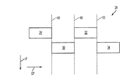
図3は、同一カラーのプリントヘッドアレイおよび異なるカラーのプリントヘッドアレイの両方において、各プリントヘッドアレイのステッチラインが処理方向と直交する方向においてお互いにオフセットされたプリントヘッド配置の実施形態を示す。図3において、プリントヘッドアレイ24Aおよび24Bは画像受信面上に第1カラーを付着させ、プリントヘッドアレイ24Cおよび24Dは画像受信面上に第2カラーを付着させる。図3に示すように、各プリントヘッドアレイ24A〜Dのステッチライン44A〜D、48A〜D、および50A〜Dは、他のプリントヘッドアレイの他のステッチラインの各々から処理方向と直交する方向においてオフセットされている。1つの実施形態では、各プリントヘッドアレイ24A〜Dのステッチライン44A〜D、48A〜D、および50A〜Dは、他のプリントヘッドアレイのステッチラインからステッチオフセット値Bだけオフセットされている。尚、このステッチオフセット値Bは上述のように、少なくとも1mmであってもよいが、適切であればどのような値であってもよい。図3の実施形態では、第1カラーのプリントヘッドアレイ24Aおよび24Bはステッチオフセット値Aだけ処理方向と直交する方向CPにオフセットまたはシフトされている。同様に、第2カラーのプリントヘッド24Cおよび24Dは、ステッチオフセット値Aだけ処理方向と直交する方向CPにオフセットまたはシフトされている。
FIG. 3 illustrates an embodiment of a printhead arrangement in which the stitch lines of each printhead array are offset from each other in a direction orthogonal to the processing direction, both in the same color printhead array and in different color printhead arrays. In FIG. 3,
同一カラーのプリントヘッドアレイをオフセットするためのステッチオフセット値Aは、異なるカラーのプリントヘッドアレイがお互いにオフセットされている距離であるステッチオフセット値Bより大きい。例えば、プリントヘッドアレイ24Bは、プリントヘッドアレイ24Cおよびプリントヘッドアレイ24Dの両方からステッチオフセット値Bだけオフセットされている。このような配置により、異なるカラープリントヘッドアレイからのステッチラインが処理方向と直交する方向に交互に現れることが可能となり、これによりプリントヘッドシステムのオフセット幅が制限される。例えば、図3で示すように、プリントヘッドアレイ24Dのステッチライン44D、48Dおよび50Dは方向CPにおいて最も左側に位置し、続いて、プリントヘッドアレイ24Bのステッチライン44B、48Bおよび50B、そしてプリントヘッドアレイス24Cのステッチライン44C、48Cおよび50C、そしてプリントヘッドアレイ24Aのステッチライン44A、48Aおよび50Aと並ぶようにプリントヘッドアレイ24A〜Dは配置されている。他の多くの同様のオフセット配置が採用可能であり、この開示の範囲内で考えられる。図3に示すステッチオフセット値Bはそれぞれ同一の距離であってもよいが、同一でなくてもよい。例えば、図3に示す各ステッチオフセット値Bは、プリントヘッド間の異なるオフセット距離に対応してもよい。同様に、各ステッチオフセット値Aは同一でも異なる距離でもよい。
The stitch offset value A for offsetting the same color printhead array is greater than the stitch offset value B, which is the distance that the different color printhead arrays are offset from each other. For example, the
1つの実施形態では、プリントヘッドアレイを画像受信面に対して固定または定常位置に取り付けることにより、プリントヘッドアレイのステッチラインが上述の状態で互いにオフセットされる。あるいは、プリントヘッドアレイを処理方向と直交する方向と平行な軸に沿って移動可能とすることにより、画像受信面上にマーキング材を付着して画像を形成する前に、プリントヘッドアレイのステッチラインが互いにオフセット可能な位置にプリントヘッドアレイを移動または平行移動することが可能となる。 In one embodiment, the printhead array stitch lines are offset from each other in the manner described above by mounting the printhead array in a fixed or stationary position relative to the image receiving surface. Alternatively, the print head array can be moved along an axis parallel to the direction orthogonal to the processing direction, so that the stitch line of the print head array is formed before the marking material is deposited on the image receiving surface to form an image. It is possible to move or translate the print head array to a position where they can be offset from each other.
プリントヘッドアレイがシフトされると、(いくつかのヘッドだけがこれらの領域にずれ込むので)プリントヘッドシステムの幅部分は十分な密度の画像を印刷することができなくなる場合がある。本開示では、これらの領域を特定のプロセス制御および/またはタイミングパッチに使用することにより、フル画像領域内でこれらの制御およびパッチの印刷が必要な場合に画像領域を拡張することを提案している。 When the printhead array is shifted, the width portion of the printhead system may not be able to print a sufficiently dense image (since only a few heads will slip into these areas). The present disclosure proposes to use these areas for specific process control and / or timing patches to expand the image area when printing of these controls and patches is required within the full image area. Yes.
上述のさまざまな実施形態ならびにその他の特徴および機能またはその代替案を適宜に組み合わせることにより、他の多くの異なるシステム、アプリケーションまたは方法を得ることができるであろう。さまざまな現状では予見し得ない、予期せぬ代替案、変形、変更または改善は、当業者によっていずれ実施されるものであって、添付の特許請求の範囲内のものである。 Many other different systems, applications, or methods may be obtained by appropriately combining the various embodiments described above and other features and functions or alternatives thereof. Unexpected alternatives, modifications, changes or improvements that cannot be foreseen under various circumstances will be implemented by those skilled in the art and are within the scope of the appended claims.
10 作像装置、18 プリントヘッドシステム、20 プリントコントローラ、22 画像パス、24 プリントヘッドアレイ、28,30,32,34,36,38 プリントヘッド、44,48,50 ステッチライン。 10 imagers, 18 printhead systems, 20 print controllers, 22 image paths, 24 printhead arrays, 28, 30, 32, 34, 36, 38 printheads, 44, 48, 50 stitch lines.
Claims (3)
マーキング材を前記画像受信面上に付着させるよう配置された複数のプリントヘッドアレイを備え、前記複数の各プリントヘッドアレイは前記処理方向の異なる位置に配置され、各プリントヘッドアレイは前記画像受信面を横切るように処理方向と直交する方向に配列された複数のプリントヘッドを含み、各プリントヘッドアレイは、前記処理方向と直交する方向と平行な軸に沿った位置に対応する少なくとも1つのステッチラインを含み、前記位置では前記プリントヘッドアレイの1つのプリントヘッドの端部が、前記プリントヘッドアレイの別のプリントヘッドの端部と実質的に一列に並び、
各プリントヘッドアレイの前記少なくとも1つのステッチラインは、前記他のプリントヘッドアレイの各々の前記少なくとも1つのステッチラインから前記処理方向と直交する方向に所定距離だけオフセットされており、
前記複数のプリントヘッドアレイは、前記画像受信面上に第1カラーのマーキング材を付着させるための少なくとも2つのプリントヘッドアレイと、前記画像受信面上に第2カラーのマーキング材を付着するための少なくとも2つのプリントヘッドアレイを含み、
前記第1カラーを付着するための前記少なくとも2つのプリントヘッドアレイにおける各プリントヘッドアレイの少なくとも1つのステッチラインは、前記第1カラーを付着するための前記少なくとも2つのプリントヘッドアレイにおける他の全てのプリントヘッドアレイの前記少なくとも1つのステッチラインから前記処理方向と直交する方向に第1所定距離だけオフセットされており、前記第2カラーを付着するための前記少なくとも2つのプリントヘッドアレイの各プリントヘッドアレイの前記少なくとも1つのステッチラインから前記処理方向と直交する方向に前記第1所定距離と異なる第2所定距離だけオフセットされていることを特徴とする作像装置。 An image receiving surface configured to move in the processing direction within the imaging device;
A plurality of print head arrays arranged to deposit marking material on the image receiving surface, wherein each of the plurality of print head arrays is arranged at a different position in the processing direction, and each print head array is arranged on the image receiving surface; At least one stitch line corresponding to a position along an axis parallel to the direction orthogonal to the processing direction. In which the end of one print head of the print head array is substantially aligned with the end of another print head of the print head array;
The at least one stitch line of each printhead array is offset from the at least one stitch line of each of the other printhead arrays by a predetermined distance in a direction orthogonal to the processing direction ;
The plurality of print head arrays includes at least two print head arrays for depositing a first color marking material on the image receiving surface, and a second color marking material for depositing the second color marking material on the image receiving surface. Including at least two printhead arrays;
At least one stitch line of each printhead array in the at least two printhead arrays for depositing the first color is the same as all other printhead arrays in the at least two printhead arrays for depositing the first color. Each printhead array of the at least two printhead arrays for depositing the second color offset from the at least one stitch line of the printhead array by a first predetermined distance in a direction orthogonal to the processing direction of said at least one from said stitch line in a direction perpendicular to the process direction first predetermined distance is different from the second predetermined distance image forming apparatus characterized that you have been offset.
処理方向に連続して配置された複数のプリントヘッドアレイを備え、各プリントヘッドアレイはマーキング材を射出するように構成され、処理方向と直交する方向に配列された複数のプリントヘッドを含み、各プリントヘッドアレイは、前記処理方向と直交する方向と平行な軸に沿った位置に対応する少なくとも1つのステッチラインを含み、前記位置では前記プリントヘッドアレイの1つのプリントヘッドの端部が、前記プリントヘッドアレイの別のプリントヘッドの端部と実質的に一列に並び、
各プリントヘッドアレイの前記少なくとも1つのステッチラインは、前記他の各プリントヘッドアレイの前記少なくとも1つのステッチラインから前記処理方向と直交する方向に所定距離だけオフセットされており、
前記複数のプリントヘッドアレイは、前記作像装置内を処理方向に移動するよう構成された画像受信面上に第1カラーのマーキング材を付着させるための少なくとも2つのプリントヘッドアレイと、前記画像受信面上に第2カラーのマーキング材を付着するための少なくとも2つのプリントヘッドアレイを含み、
前記第1カラーを付着するための前記少なくとも2つのプリントヘッドアレイにおける各プリントヘッドアレイの少なくとも1つのステッチラインは、前記第1カラーを付着するための前記少なくとも2つのプリントヘッドアレイにおける他の全てのプリントヘッドアレイの前記少なくとも1つのステッチラインから前記処理方向と直交する方向に第1所定距離だけオフセットされており、前記第2カラーを付着するための前記少なくとも2つのプリントヘッドアレイの各プリントヘッドアレイの前記少なくとも1つのステッチラインから前記処理方向と直交する方向に前記第1所定距離と異なる第2所定距離だけオフセットされていることを特徴とするプリントヘッドシステム。
A print head system for use in an imaging device,
A plurality of printhead arrays arranged in succession in the processing direction, each printhead array being configured to emit marking material and including a plurality of printheads arranged in a direction orthogonal to the processing direction, The printhead array includes at least one stitch line corresponding to a position along an axis parallel to a direction orthogonal to the processing direction, at which the end of one printhead of the printhead array is the printhead array. Substantially aligned with the end of another print head in the head array,
The at least one stitch line of each print head array is offset from the at least one stitch line of each of the other print head arrays by a predetermined distance in a direction perpendicular to the processing direction ;
The plurality of print head arrays includes at least two print head arrays for depositing a first color marking material on an image receiving surface configured to move in the processing direction within the imaging device; and the image receiving Including at least two printhead arrays for depositing a second color marking material on the surface;
At least one stitch line of each printhead array in the at least two printhead arrays for depositing the first color is the same as all other printhead arrays in the at least two printhead arrays for depositing the first color. Each printhead array of the at least two printhead arrays for depositing the second color offset from the at least one stitch line of the printhead array by a first predetermined distance in a direction orthogonal to the processing direction wherein the at least one print head system according to claim Rukoto from stitch line has just been offset a second predetermined distance different from the first predetermined distance in a direction perpendicular to the process direction.
Applications Claiming Priority (2)
| Application Number | Priority Date | Filing Date | Title |
|---|---|---|---|
| US12/504,857 US8167404B2 (en) | 2009-07-17 | 2009-07-17 | Staggered head stitch shifts in a continuous feed direct marking printer |
| US12/504,857 | 2009-07-17 |
Publications (3)
| Publication Number | Publication Date |
|---|---|
| JP2011020451A JP2011020451A (en) | 2011-02-03 |
| JP2011020451A5 JP2011020451A5 (en) | 2013-08-15 |
| JP5427716B2 true JP5427716B2 (en) | 2014-02-26 |
Family
ID=42790572
Family Applications (1)
| Application Number | Title | Priority Date | Filing Date |
|---|---|---|---|
| JP2010161189A Expired - Fee Related JP5427716B2 (en) | 2009-07-17 | 2010-07-16 | Staggered head stitch shift in continuous feed direct marking printer |
Country Status (5)
| Country | Link |
|---|---|
| US (1) | US8167404B2 (en) |
| EP (1) | EP2275266B1 (en) |
| JP (1) | JP5427716B2 (en) |
| KR (1) | KR101248049B1 (en) |
| CN (1) | CN101954787B (en) |
Families Citing this family (11)
| Publication number | Priority date | Publication date | Assignee | Title |
|---|---|---|---|---|
| US8452725B2 (en) * | 2008-09-03 | 2013-05-28 | Hamid Hatami-Hanza | System and method of ontological subject mapping for knowledge processing applications |
| US8427695B2 (en) * | 2009-07-15 | 2013-04-23 | Eastman Kodak Company | Setting of imaging parameters |
| US8167404B2 (en) | 2009-07-17 | 2012-05-01 | Xerox Corporation | Staggered head stitch shifts in a continuous feed direct marking printer |
| US8087753B2 (en) | 2010-01-19 | 2012-01-03 | Xerox Corporation | Method for modular arrangement of a silicon based array and modular silicon based array |
| US8292398B2 (en) | 2010-05-14 | 2012-10-23 | Xerox Corporation | Method and system for printhead alignment to compensate for dimensional changes in a media web in an inkjet printer |
| US8517502B2 (en) * | 2011-02-14 | 2013-08-27 | Xerox Corporation | Method and system for printhead alignment to reduce or eliminate banding artifacts for interlaced printheads |
| US8939546B2 (en) | 2012-07-12 | 2015-01-27 | Hewlett-Packard Industrial Printing Ltd. | Coordinated printhead operation |
| US8807692B2 (en) | 2012-07-31 | 2014-08-19 | Eastman Kodak Company | Incorrect stitching detection in a printing system |
| US9434155B1 (en) | 2015-08-31 | 2016-09-06 | Xerox Corporation | Method and system for printhead alignment based on print medium width |
| US9908324B1 (en) | 2017-02-27 | 2018-03-06 | Eastman Kodak Company | Printing with overlapping printheads |
| EP3547221B1 (en) | 2018-03-28 | 2021-07-07 | Heidelberger Druckmaschinen AG | Method for printing the surface of an object |
Family Cites Families (28)
| Publication number | Priority date | Publication date | Assignee | Title |
|---|---|---|---|---|
| GB8810241D0 (en) * | 1988-04-29 | 1988-06-02 | Am Int | Drop-on-demand printhead |
| US5093674A (en) | 1990-08-02 | 1992-03-03 | Hewlett-Packard Company | Method and system for compensating for paper shrinkage and misalignment in electrophotographic color printing |
| US5406321A (en) | 1993-04-30 | 1995-04-11 | Hewlett-Packard Company | Paper preconditioning heater for ink-jet printer |
| US6017113A (en) | 1993-10-29 | 2000-01-25 | Hewlett-Packard Company | Mixed-density print masking in a mixed-swath-height printer |
| JPH11102033A (en) | 1997-09-26 | 1999-04-13 | Noritsu Koki Co Ltd | Method for correctly carrying sheet member and carrying device |
| JP2000006389A (en) * | 1998-06-29 | 2000-01-11 | Konica Corp | Ink jet printer |
| US6788432B1 (en) | 1998-09-09 | 2004-09-07 | Hewlett-Packard Development Company, L.P. | Optimal-size and nozzle-modulated printmasks for use in incremental printing |
| US6502920B1 (en) | 2000-02-04 | 2003-01-07 | Lexmark International, Inc | Ink jet print head having offset nozzle arrays |
| US6536894B1 (en) | 2000-06-06 | 2003-03-25 | Hewlett-Packard Company | Print media heating techniques for a vacuum belt hard copy apparatus |
| DE10040368C2 (en) | 2000-08-18 | 2002-12-12 | Nexpress Solutions Llc | Method and device for setting devices for generating partial color images in a multicolor printing machine |
| US6412907B1 (en) | 2001-01-24 | 2002-07-02 | Xerox Corporation | Stitching and color registration control for multi-scan printing |
| US6663206B2 (en) | 2002-01-16 | 2003-12-16 | Xerox Corporation | Systems and method for masking stitch errors |
| US7044573B2 (en) | 2002-02-20 | 2006-05-16 | Lexmark International, Inc. | Printhead alignment test pattern and method for determining printhead misalignment |
| US6840615B2 (en) * | 2002-12-16 | 2005-01-11 | Xerox Corporation | Imaging surface field reconditioning method and apparatus |
| KR100490427B1 (en) | 2003-02-14 | 2005-05-17 | 삼성전자주식회사 | Calibrating method of print alignment error |
| JP4691874B2 (en) * | 2003-05-14 | 2011-06-01 | セイコーエプソン株式会社 | Droplet discharge device and color filter manufacturing device |
| JP4027358B2 (en) * | 2003-12-15 | 2007-12-26 | キヤノン株式会社 | Ink jet head and ink jet recording apparatus using the head |
| US6799830B1 (en) | 2004-01-10 | 2004-10-05 | Xerox Corporation | Drop generating apparatus |
| US7273262B2 (en) | 2004-06-23 | 2007-09-25 | Hewlett-Packard Development Company, L.P. | System with alignment information |
| US7309118B2 (en) | 2004-11-30 | 2007-12-18 | Xerox Corporation | Systems and methods for reducing cross process direction registration errors of a printhead using a linear array sensor |
| US7691280B2 (en) | 2005-03-25 | 2010-04-06 | E. I. Du Pont De Nemours And Company | Ink jet printing of etchants and modifiers |
| US7665817B2 (en) | 2006-11-29 | 2010-02-23 | Xerox Corporation | Double reflex printing |
| JP5178071B2 (en) * | 2007-07-06 | 2013-04-10 | キヤノン株式会社 | Inkjet recording apparatus and inkjet recording method |
| JP2009061621A (en) * | 2007-09-05 | 2009-03-26 | Seiko Epson Corp | Liquid jet apparatus and liquid jet method |
| US20090141110A1 (en) | 2007-11-30 | 2009-06-04 | Xerox Corporation | Ink-jet printer using phase-change ink for direct on paper printing |
| EP2127892B1 (en) | 2008-05-28 | 2012-02-08 | Digital Information Ltd. (AG) | Apparatus for and method of producing proof prints |
| US7837290B2 (en) | 2008-07-18 | 2010-11-23 | Xerox Corporation | Continuous web printing system alignment method |
| US8167404B2 (en) | 2009-07-17 | 2012-05-01 | Xerox Corporation | Staggered head stitch shifts in a continuous feed direct marking printer |
-
2009
- 2009-07-17 US US12/504,857 patent/US8167404B2/en not_active Expired - Fee Related
-
2010
- 2010-07-15 KR KR1020100068270A patent/KR101248049B1/en active IP Right Grant
- 2010-07-16 JP JP2010161189A patent/JP5427716B2/en not_active Expired - Fee Related
- 2010-07-16 CN CN201010232228.5A patent/CN101954787B/en not_active Expired - Fee Related
- 2010-07-16 EP EP10169752.2A patent/EP2275266B1/en not_active Not-in-force
Also Published As
| Publication number | Publication date |
|---|---|
| EP2275266A1 (en) | 2011-01-19 |
| US20110012958A1 (en) | 2011-01-20 |
| CN101954787A (en) | 2011-01-26 |
| KR101248049B1 (en) | 2013-03-27 |
| EP2275266B1 (en) | 2013-09-11 |
| KR20110007960A (en) | 2011-01-25 |
| US8167404B2 (en) | 2012-05-01 |
| CN101954787B (en) | 2014-05-14 |
| JP2011020451A (en) | 2011-02-03 |
Similar Documents
| Publication | Publication Date | Title |
|---|---|---|
| JP5427716B2 (en) | Staggered head stitch shift in continuous feed direct marking printer | |
| EP1705014B1 (en) | Ink jet printing apparatus and ink jet printing method | |
| EP1734736B1 (en) | Compensation for malfunctioning jets | |
| JP2011056880A (en) | Image recorder and method of adjusting image recorder | |
| US6938970B2 (en) | Printing methods and apparatus for multi-pass printing | |
| JP4983420B2 (en) | Liquid ejection apparatus and liquid ejection method | |
| US8210631B2 (en) | Method for minimizing printing defects due to missing nozzle in media processing device | |
| JP5108790B2 (en) | Printing apparatus using a plurality of print cartridges | |
| US8500236B2 (en) | Computer based method and system for adjusting page placement on a continuous feed print engine | |
| CN102729645B (en) | duplex printing system and method for operating the printer | |
| US7396107B2 (en) | Ink jet printing with low coverage second pass | |
| US8031372B2 (en) | System and method for distributing image values of a color separation | |
| JP5427539B2 (en) | System and method for recording images in a single pass to a plurality of serially arranged printheads | |
| US8668294B2 (en) | Method and system for split head drop size printing | |
| EP1382457A1 (en) | Printing methods and apparatus for multi-pass printing | |
| JP2003305830A (en) | Recording apparatus and recording method | |
| JP5035203B2 (en) | Liquid ejection apparatus and liquid ejection method | |
| JP2010179552A (en) | Liquid jetting device and printing method | |
| JP2004216793A (en) | Printer | |
| US20110111125A1 (en) | Dithered Printing of Clear Ink to Reduce Rub and Offset | |
| JP2001130040A (en) | Recording method and printer using the same | |
| JP2009226703A (en) | Detection mark, detecting method, image drawing method, and drafting equipment | |
| JP2010069641A (en) | Image forming apparatus and image forming method |
Legal Events
| Date | Code | Title | Description |
|---|---|---|---|
| A521 | Request for written amendment filed |
Free format text: JAPANESE INTERMEDIATE CODE: A523 Effective date: 20130703 |
|
| A621 | Written request for application examination |
Free format text: JAPANESE INTERMEDIATE CODE: A621 Effective date: 20130703 |
|
| A871 | Explanation of circumstances concerning accelerated examination |
Free format text: JAPANESE INTERMEDIATE CODE: A871 Effective date: 20130703 |
|
| A975 | Report on accelerated examination |
Free format text: JAPANESE INTERMEDIATE CODE: A971005 Effective date: 20130729 |
|
| A131 | Notification of reasons for refusal |
Free format text: JAPANESE INTERMEDIATE CODE: A131 Effective date: 20130806 |
|
| A521 | Request for written amendment filed |
Free format text: JAPANESE INTERMEDIATE CODE: A523 Effective date: 20131015 |
|
| TRDD | Decision of grant or rejection written | ||
| A01 | Written decision to grant a patent or to grant a registration (utility model) |
Free format text: JAPANESE INTERMEDIATE CODE: A01 Effective date: 20131105 |
|
| A61 | First payment of annual fees (during grant procedure) |
Free format text: JAPANESE INTERMEDIATE CODE: A61 Effective date: 20131202 |
|
| R150 | Certificate of patent or registration of utility model |
Free format text: JAPANESE INTERMEDIATE CODE: R150 Ref document number: 5427716 Country of ref document: JP Free format text: JAPANESE INTERMEDIATE CODE: R150 |
|
| R250 | Receipt of annual fees |
Free format text: JAPANESE INTERMEDIATE CODE: R250 |
|
| R250 | Receipt of annual fees |
Free format text: JAPANESE INTERMEDIATE CODE: R250 |
|
| R250 | Receipt of annual fees |
Free format text: JAPANESE INTERMEDIATE CODE: R250 |
|
| R250 | Receipt of annual fees |
Free format text: JAPANESE INTERMEDIATE CODE: R250 |
|
| LAPS | Cancellation because of no payment of annual fees |