EP2275266B1 - Staggered head stitch shifts in a continuous feed direct marking printer - Google Patents
Staggered head stitch shifts in a continuous feed direct marking printer Download PDFInfo
- Publication number
- EP2275266B1 EP2275266B1 EP10169752.2A EP10169752A EP2275266B1 EP 2275266 B1 EP2275266 B1 EP 2275266B1 EP 10169752 A EP10169752 A EP 10169752A EP 2275266 B1 EP2275266 B1 EP 2275266B1
- Authority
- EP
- European Patent Office
- Prior art keywords
- printhead
- array
- arrays
- receiving surface
- process direction
- Prior art date
- Legal status (The legal status is an assumption and is not a legal conclusion. Google has not performed a legal analysis and makes no representation as to the accuracy of the status listed.)
- Not-in-force
Links
Images


Classifications
-
- B—PERFORMING OPERATIONS; TRANSPORTING
- B41—PRINTING; LINING MACHINES; TYPEWRITERS; STAMPS
- B41J—TYPEWRITERS; SELECTIVE PRINTING MECHANISMS, i.e. MECHANISMS PRINTING OTHERWISE THAN FROM A FORME; CORRECTION OF TYPOGRAPHICAL ERRORS
- B41J2/00—Typewriters or selective printing mechanisms characterised by the printing or marking process for which they are designed
- B41J2/005—Typewriters or selective printing mechanisms characterised by the printing or marking process for which they are designed characterised by bringing liquid or particles selectively into contact with a printing material
- B41J2/01—Ink jet
- B41J2/135—Nozzles
- B41J2/145—Arrangement thereof
Definitions
- This disclosure relates generally to imaging devices having multiple printhead arrays, and more particularly, to the arrangement of the multiple printhead arrays in such imaging devices.
- WO 01/56798A1 discloses an ink jet printing apparatus that comprises a printhead comprising first and second substantially columnar nozzle arrays, each aligned with a print medium advance direction.
- Each substantially columnar array has an upper sub-array pair including an upper left and an upper right sub-array of nozzles.
- Each upper right sub-array is offset from the corresponding upper left sub-array in the scan direction by a first spacing and in the print medium advance direction by one half of the nozzle to nozzle spacing.
- the second substantially columnar array is offset from the first substantially columnar array in the scan direction by a second spacing and in the print medium advance direction by one fourth of the nozzle to nozzle spacing.
- Some ink printing devices use a single printhead, but many use a plurality of printheads to increase the rate of printing.
- some devices utilize a plurality of printhead arrays in which each array has multiple printheads arranged end to end across an image receiving surface.
- the ends of the printheads of an array are aligned at locations referred to as stitch lines or stitch joints.
- Differences in printing characteristics of the printheads on either side of a stitch line such as drop mass, position or some other attribute, may result in visible stitch line defects between printheads.
- Stitch line defects may exhibit as either a specific line defect at the stitch joint or as a density shift between printheads. In either case, stitch line defects may result in an image quality defect known as banding that extends in the process direction on a printed media.
- a printhead system according to the present invention comprises the features defined in claim 1.
- a method of arranging print head arrays in an imaging device according to the present invention comprises the features defined in claim 10.
- Embodiments of the present invention can comprise the features defined in the dependent claims.
- an imaging device includes an image receiving surface configured to move in a process direction in the imaging device.
- a plurality of printhead arrays are arranged to deposit marking material onto the image receiving surface.
- Each printhead array includes a plurality of printheads arrayed in a cross-process direction across the image receiving surface.
- Each printhead array includes at least one stitch line corresponding to a position along an axis parallel to the cross-process direction where an end of one printhead in the printhead array aligns with an end of another printhead in the printhead array.
- the at least one stitch line of each printhead array is offset a predetermined distance in the cross-process direction from the at least one stitch line of each of the other printhead arrays.
- a method of arranging printhead arrays in an imaging device includes the arrangement of a first printhead array adjacent an image receiving surface at a first location in a process direction of the image receiving surface.
- the first printhead array includes at least one first stitch line corresponding to locations in the first printhead array where an end of one printhead in the first printhead array is aligned with an end of a next printhead in the first printhead array.
- the at least one first stitch line is located at a first position in the cross-process direction.
- a second printhead array is arranged adjacent the image receiving surface at a second location in the process direction of the image receiving surface.
- the second printhead array includes at least one second stitch line corresponding to locations in the second printhead array where an end of one printhead in the second printhead array is aligned with an end of a next printhead in the second printhead array.
- the at least one second stitch line is located at a second position in the cross-process direction different than the first position.
- the first printhead array and the second printhead array being configured to deposit marking material of a first color onto the image receiving surface
- the third printhead array being configured to deposit marking material of a second color onto the image receiving surface; and the arrangement of the first, second, and third printhead arrays further comprising:
- the terms "printer” or “imaging device” generally refer to a device for applying an image to print media and may encompass any apparatus, such as a digital copier, bookmaking machine, facsimile machine, multi-function machine, etc. which performs a print outputting function for any purpose.
- Recording media can be a physical sheet of paper, plastic, or other suitable physical print media substrate for images, whether precut or web fed.
- a "print job” or “document” is normally a set of related sheets, usually one or more collated copy sets copied from a set of original print job sheets or electronic document page images, from a particular user, or otherwise related.
- An image generally may include information in electronic form which is to be rendered on the print media by the marking engine and may include text, graphics, pictures, and the like.
- the process direction is the direction in which the substrate onto which the image is transferred moves through the imaging device.
- the cross-process direction, along the same plane as the substrate, is substantially perpendicular to the process direction.
- FIG. 1 is a simplified block diagram of one embodiment of an imaging device 10.
- the imaging device 10 includes an image receiving surface 14 that is transported in a process direction P in front of a printhead system 18 which deposit marking material onto the image receiving surface to form images.
- the imaging device is a direct marking imaging device in which the image receiving surface comprises a very long (i.e., substantially continuous) web W of "substrate" (paper, plastic, or other printable material) upon which the images are directly formed by the printhead system.
- the imaging device may be an indirect marking device in which the image receiving surface comprises an intermediate transfer surface, in the form of a belt or drum, upon which images may be formed and subsequently transferred to a final receiving substrate such as a web or sheet of media.
- the image receiving surface may be linear or curved, may have any suitable path including horizontal, vertical, or combinations of horizontal and vertical, and may be transported in the process direction by the printhead system in any suitable manner.
- the imaging device may utilize a single pass or multi-pass printing process. In a single pass printing process, an image is formed on the image receiving surface in a single passage of the image receiving surface past the printhead system. In a multi-pass printing process, an image is built up on the image receiving surface in multiple passages of the image receiving surface past the printhead system.
- the image receiving surface of FIG. 1 may comprise a belt or drum that is configured for rotation in front of the printhead system.
- the printhead system 18 includes a series of printhead arrays 24A-D, each printhead array including a plurality of printheads arrayed across the width of the image receiving surface in a cross-process direction, i.e., substantially perpendicular to the process direction (explained in more detail below).
- Each printhead includes a plurality of ink jets for emitting ink onto the web.
- the printheads of a printhead array may each be completely separate units mounted on a single fixed bar or positioning device.
- printheads of a printhead array may comprise groupings of similarly utilized and/or manufactured ink jet ejectors, e.g., silicon dies placed on a flat backer bar.
- each printhead array being configured to deposit ink of one color onto the image receiving surface although any suitable number of printhead arrays may be utilized.
- multiple printhead arrays may be provided for each color or shade of ink used in the imaging device.
- images of different colors formed by the different printhead arrays are placed on overlapping areas on the image receiving surface to form multi-color images, based on the image data sent to each printhead array through image path 22 from print controller 20.
- the ink utilized in the imaging device 10 is a "phase-change ink,” by which is meant that the ink is substantially solid at room temperature and substantially liquid when heated to a phase change ink melting temperature for jetting onto the imaging receiving surface.
- the phase change ink melting temperature may be any temperature that is capable of melting solid phase change ink into liquid or molten form. In one embodiment, the phase change ink melting temperature is approximately 100°C to 140°C. In alternative embodiments, however, any suitable marking material or ink may be used including, for example, toner, aqueous ink, oil-based ink, UV curable ink, or the like.
- a printhead array includes a plurality of printheads that are arrayed substantially end-to-end in a cross-process direction CP across the width of the image receiving surface 14 (not shown in FIG. 2 ).
- each printhead array 24 includes four printheads although the printhead arrays may have more or fewer printheads.
- Each printhead 32, 34, 36 and 38 of a printhead array has a corresponding front face through which marking material, such as melted phase change ink, may be emitted onto the receiving surface 14 to form images.
- the printhead array 24 comprises a staggered full width array (SFWA).
- An SFWA includes four printheads 28, 30, 32, 34 arranged in two rows with each row having two printheads.
- Each row of printheads in the SFWA is located at a different position along the process direction P of the image receiving surface path.
- the two printheads 28, 32 in the first row are separated in the direction CP by a distance corresponding to the width of a printhead.
- the first printhead 30 in the second row is positioned at a location corresponding to the gap between the two printheads 28, 32 in the first row and the last printhead 34 in the second row is separated from the first printhead 30 in the second row by a distance corresponding to the width of a printhead.
- stitch line refers to the location in the array where an end of one printhead in the array slightly overlaps the end of the next adjacent printhead in the array in the cross-process direction.
- stitch line refers to the location in the array where an end of one printhead in the array slightly overlaps the end of the next adjacent printhead in the array in the cross-process direction.
- the end of printhead 28 and an end of printhead 30 each abut or are slightly overlapped on stitch line 50.
- the other end of printhead 30 and one end of printhead 32 are slightly overlapped on stitch line 48.
- stitch lines 44, 48, 50 are generally parallel to the process direction P of the image receiving surface.
- the embodiment of the printhead array in FIG. 2 is a SFWA, other printhead array arrangements are contemplated within the scope of this disclosure.
- the printheads of a printhead array are slightly overlapped at the stitch lines so that the stitch lines correspond to an overlap zone between the printheads of a printhead array where the last few jets of each printhead are interlaced.
- the adjacent ends of printheads in a printhead array is overlapped by a number of pixels and alternate jets are printed in the overlap region.
- One example would be to overlap the last two jets of each head. Stitching the printheads of an array may also include using the last jet of each head but not the next to last jet. This would spread the stitch line over two pixels. Greater overlaps could be used by alternating every other jet in the overlap region or alternating greater multiples of jets such as pairs of jets.
- Stitch line defects show as either a specific line defect at the stitch joint between printheads or as a density shift between printheads. In either case, stitch line defects may result in an image quality defect known as banding that extends in the process direction on a printed media.
- Methods have been developed for compensating or masking stitch line defects between printheads of a printhead array. In previously known printhead systems that utilized multiple printhead arrays to form images on an image receiving surface, the stitch lines of the multiple printheads were aligned. For example, FIG.
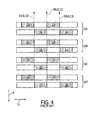
- FIG. 4 depicts a portion of a previously known printhead array arrangement that includes four printhead arrays 24A-D with two printhead arrays 24A and 24B for depositing a first color onto the image receiving surface and two printhead arrays 24C and 24D for depositing a second color onto the image receiving surface.
- the stitch lines 44A-D, 48A-D, 50A-D for each printhead array 24A-D in this previously known arrangement are aligned, e.g., the stitch lines 44A-D, 48A-D, 50A-D for each printhead array 24A-D are at the same cross-process direction CP position. Aligning the stitch lines of multiple printhead arrays in this manner may result in stitch line defects from different printhead arrays to be positioned on top of each other and become even more visible.
- a method of arranging printhead arrays involves offsetting or shifting the stitch lines of each printhead array along an axis parallel to the cross-process direction so that the stitch lines of each printhead array are at different locations in the cross-process direction than the stitch lines of at least one, and advantageously most or all of the other printhead arrays, in the imaging device.
- Offsetting or shifting the stitch lines from each printhead array in the cross-process direction form the stitch lines of the other printhead arrays causes images formed by the different printhead arrays to overlap at the stitch lines which spreads out any stitch line defects that may be generated by the printhead arrays and makes them less objectionable or visible in the resulting prints.
- One or more printhead arrays in a multiple printhead array system may be offset or shifted from the stitch lines of one or more other printhead arrays by a predetermined stitch offset value.
- a stitch offset for a printhead array refers to a distance in the cross-process direction that the stitch lines of the printhead array are offset or shifted relative to the stitch lines of at least one other printhead array.
- the cross-process direction position of the stitch lines of one or more of the printhead arrays may be considered as a reference positions from which the stitch lines of the other printhead arrays are shifted or offset.
- stitch lines may be offset or shifted in the cross-process direction from printhead array to printhead array for printhead arrays of the same color because such printhead arrays are likely to be utilized together to form images on the image receiving surface.
- stitch lines may be offset or shifted in the cross-process direction from printhead array to printhead array only for printhead arrays of different colors.
- Stitch offsets may be any suitable distance in the cross-process direction, and may be the same or different for each printhead array (that is desired to be offset) in the multiple printhead arrays of an imaging device.
- stitch offsets between printhead arrays of the same color are at least 1mm, and in one particular embodiment, at least 4mm, and stitch offsets between printhead arrays of different colors or shades may be at least 1 mm. Accordingly, in one embodiment, all arrays of all colors are shifted in a manner so that no stitch line from any array is within 1mm of any other stitch line.
- FIG. 3 shows an embodiment of a printhead arrangement in which the stitch lines of each printhead array are offset from each other in the cross-process direction for both printhead arrays of the same color as well as for printhead arrays of different colors.
- printhead arrays 24A and 24B are for depositing a first color onto the image receiving surface and printhead arrays 24C and 24D are for depositing a second color onto the image receiving surface.
- the stitch lines 44A-D, 48A-D, and 50A-D of each printhead array 24A-D are offset in the cross-process direction from each of the other stitch lines of the other printhead arrays.
- the stitch lines 44A-D, 48A-D, and 50A-D of each printhead array 24A-D are offset from the stitch lines of other printhead arrays by a stitch offset B which, as explained above, may be at least 1mm although any suitable offset value may be used.
- a stitch offset B which, as explained above, may be at least 1mm although any suitable offset value may be used.
- printhead arrays 24A and 24B of the first color are offset or shifted in the cross-process direction CP by a stitch offset A.
- printhead arrays 24C and 24D of the second color are offset or shifted in the cross-process direction CP by the stitch offset A.
- Stitch offset A for offsetting the printhead arrays of the same color is greater than the stitch offset B which is the distance that printhead arrays of different colors are offset from each other.
- stitch offset B is the distance that printhead arrays of different colors are offset from each other.
- printhead array 24B is offset from both printhead array 24C and printhead array 24D by the stitch offset B.
- the printhead arrays 24A-D are arranged such that the stitch lines 44D, 48D, and 50D of printhead array 24D are the farthest left relative to the direction CP, followed by the stitch lines 44B, 48B, and 50B of printhead array 24B, then stitch lines 44C, 48C, and 50C of printhead array 24C, and then stitch lines 44A, 48A, and 50A of printhead array 24A.
- the stitch offsets B depicted in FIG. 3 may each be the same distance although not necessarily.
- each stitch offset B depicted in FIG. 3 may each correspond to a different offset distance between printheads.
- each stitch offset A may be the same or different distances.
- the printhead arrays are mounted in fixed or stationary positions relative to the image receiving surface so that the stitch lines of the printhead arrays are offset from each other in the manner described above.
- the printhead arrays may be capable of translating along an axis parallel to the cross-process direction so that the printhead arrays may be moved or translated to positions that enable the stitch lines of the printhead arrays to be offset from each other prior to depositing marking material onto the image receiving surface to form images.
- portions of width of the printhead system may be incapable of printing full density images (because only some of the heads will overlap into these zones).
- the present disclosure proposes that these zones may be used for certain process controls and/or timing patches thus expanding the imaging zone if one had to print those controls and patches within the full imaging areas.
Description
- This disclosure relates generally to imaging devices having multiple printhead arrays, and more particularly, to the arrangement of the multiple printhead arrays in such imaging devices.
-
WO 01/56798A1 - Some ink printing devices use a single printhead, but many use a plurality of printheads to increase the rate of printing. For example, some devices utilize a plurality of printhead arrays in which each array has multiple printheads arranged end to end across an image receiving surface. The ends of the printheads of an array are aligned at locations referred to as stitch lines or stitch joints. Differences in printing characteristics of the printheads on either side of a stitch line, such as drop mass, position or some other attribute, may result in visible stitch line defects between printheads. Stitch line defects may exhibit as either a specific line defect at the stitch joint or as a density shift between printheads. In either case, stitch line defects may result in an image quality defect known as banding that extends in the process direction on a printed media. Methods have been developed for compensating or masking stitch line defects between printheads of a printhead array. In previously known printhead systems that utilize multiple printhead arrays to form images on an image receiving surface, the stitch lines of the multiple printheads were aligned. Aligning the stitch lines of multiple printhead arrays may cause stitch line defects from different printhead arrays to coincide and become even more visible.
- A printhead system according to the present invention comprises the features defined in
claim 1. - A method of arranging print head arrays in an imaging device according to the present invention comprises the features defined in
claim 10. - Embodiments of the present invention can comprise the features defined in the dependent claims.
- The present disclosure proposes an arrangement of printhead arrays in a multiple printhead array system that prevents or limits cumulative stitch line defects from occurring. In particular, in one embodiment, an imaging device includes an image receiving surface configured to move in a process direction in the imaging device. A plurality of printhead arrays are arranged to deposit marking material onto the image receiving surface. Each printhead array includes a plurality of printheads arrayed in a cross-process direction across the image receiving surface. Each printhead array includes at least one stitch line corresponding to a position along an axis parallel to the cross-process direction where an end of one printhead in the printhead array aligns with an end of another printhead in the printhead array. The at least one stitch line of each printhead array is offset a predetermined distance in the cross-process direction from the at least one stitch line of each of the other printhead arrays.
- In another embodiment, a method of arranging printhead arrays in an imaging device is provided. The method includes the arrangement of a first printhead array adjacent an image receiving surface at a first location in a process direction of the image receiving surface. The first printhead array includes at least one first stitch line corresponding to locations in the first printhead array where an end of one printhead in the first printhead array is aligned with an end of a next printhead in the first printhead array. The at least one first stitch line is located at a first position in the cross-process direction. A second printhead array is arranged adjacent the image receiving surface at a second location in the process direction of the image receiving surface. The second printhead array includes at least one second stitch line corresponding to locations in the second printhead array where an end of one printhead in the second printhead array is aligned with an end of a next printhead in the second printhead array. The at least one second stitch line is located at a second position in the cross-process direction different than the first position. In a further embodiment the first printhead array and the second printhead array being configured to deposit marking material of a first color onto the image receiving surface, and the third printhead array being configured to deposit marking material of a second color onto the image receiving surface; and the arrangement of the first, second, and third printhead arrays further comprising:
- arranging the first, second, and third printhead arrays such that the second position is offset from the first position by a first predetermined distance, and the third position is offset from the first position by a second predetermined distance that is less than the first predetermined distance.
In a further embodiment the image receiving surface comprising a substantially continuous media web.
In a further embodiment, the image receiving surface comprising an intermediate transfer surface.
In a further embodiment, each of the first, second, and third printhead arrays comprising a staggered full width array printhead having three or more printheads.
In one embodiment of the system of claim 15, the predetermined distance is at least 1 mm. -
-
FIG. 1 is a simplified elevational view of an embodiment of an imaging device. -
FIG. 2 is a simplified elevational view of a printhead array of the imaging device ofFIG. 1 . -
FIG. 3 is an embodiment of an arrangement of the printhead arrays of the imaging device ofFIG. 1 in which the stitch lines of the printhead arrays are offset from each other. -
FIG. 4 is a prior art view of an arrangement of printhead arrays showing the stitch lines of the printhead arrays aligned with each other. - For a general understanding of the present embodiments, reference is made to the drawings. In the drawings, like reference numerals have been used throughout to designate like elements.
- As used herein, the terms "printer" or "imaging device" generally refer to a device for applying an image to print media and may encompass any apparatus, such as a digital copier, bookmaking machine, facsimile machine, multi-function machine, etc. which performs a print outputting function for any purpose. "Recording media" can be a physical sheet of paper, plastic, or other suitable physical print media substrate for images, whether precut or web fed. A "print job" or "document" is normally a set of related sheets, usually one or more collated copy sets copied from a set of original print job sheets or electronic document page images, from a particular user, or otherwise related. An image generally may include information in electronic form which is to be rendered on the print media by the marking engine and may include text, graphics, pictures, and the like. As used herein, the process direction is the direction in which the substrate onto which the image is transferred moves through the imaging device. The cross-process direction, along the same plane as the substrate, is substantially perpendicular to the process direction.
-
FIG. 1 is a simplified block diagram of one embodiment of animaging device 10. As depicted inFIG. 1 , theimaging device 10 includes animage receiving surface 14 that is transported in a process direction P in front of aprinthead system 18 which deposit marking material onto the image receiving surface to form images. In one embodiment, the imaging device is a direct marking imaging device in which the image receiving surface comprises a very long (i.e., substantially continuous) web W of "substrate" (paper, plastic, or other printable material) upon which the images are directly formed by the printhead system. Alternatively, the imaging device may be an indirect marking device in which the image receiving surface comprises an intermediate transfer surface, in the form of a belt or drum, upon which images may be formed and subsequently transferred to a final receiving substrate such as a web or sheet of media. The image receiving surface may be linear or curved, may have any suitable path including horizontal, vertical, or combinations of horizontal and vertical, and may be transported in the process direction by the printhead system in any suitable manner. In addition, the imaging device may utilize a single pass or multi-pass printing process. In a single pass printing process, an image is formed on the image receiving surface in a single passage of the image receiving surface past the printhead system. In a multi-pass printing process, an image is built up on the image receiving surface in multiple passages of the image receiving surface past the printhead system. For example, the image receiving surface ofFIG. 1 may comprise a belt or drum that is configured for rotation in front of the printhead system. - The
printhead system 18 includes a series ofprinthead arrays 24A-D, each printhead array including a plurality of printheads arrayed across the width of the image receiving surface in a cross-process direction, i.e., substantially perpendicular to the process direction (explained in more detail below). Each printhead includes a plurality of ink jets for emitting ink onto the web. The printheads of a printhead array may each be completely separate units mounted on a single fixed bar or positioning device. Alternatively, printheads of a printhead array may comprise groupings of similarly utilized and/or manufactured ink jet ejectors, e.g., silicon dies placed on a flat backer bar. - For simplicity, four printhead arrays are shown in
FIG. 1 , each printhead array being configured to deposit ink of one color onto the image receiving surface although any suitable number of printhead arrays may be utilized. As explained below, multiple printhead arrays may be provided for each color or shade of ink used in the imaging device. As is generally familiar, images of different colors formed by the different printhead arrays are placed on overlapping areas on the image receiving surface to form multi-color images, based on the image data sent to each printhead array through image path 22 fromprint controller 20. - In one embodiment, the ink utilized in the
imaging device 10 is a "phase-change ink," by which is meant that the ink is substantially solid at room temperature and substantially liquid when heated to a phase change ink melting temperature for jetting onto the imaging receiving surface. The phase change ink melting temperature may be any temperature that is capable of melting solid phase change ink into liquid or molten form. In one embodiment, the phase change ink melting temperature is approximately 100°C to 140°C. In alternative embodiments, however, any suitable marking material or ink may be used including, for example, toner, aqueous ink, oil-based ink, UV curable ink, or the like. - Referring now to
FIG. 2 , an embodiment of a printhead array is depicted. A printhead array includes a plurality of printheads that are arrayed substantially end-to-end in a cross-process direction CP across the width of the image receiving surface 14 (not shown inFIG. 2 ). In the embodiment ofFIG. 2 , eachprinthead array 24 includes four printheads although the printhead arrays may have more or fewer printheads. Eachprinthead surface 14 to form images. - In the embodiment of
FIG. 2 , theprinthead array 24 comprises a staggered full width array (SFWA). An SFWA includes fourprintheads printheads first printhead 30 in the second row is positioned at a location corresponding to the gap between the twoprintheads last printhead 34 in the second row is separated from thefirst printhead 30 in the second row by a distance corresponding to the width of a printhead. - The ends of the printheads of the SFWA are aligned at
stitch lines FIG. 2 , the end ofprinthead 28 and an end ofprinthead 30 each abut or are slightly overlapped onstitch line 50. The other end ofprinthead 30 and one end ofprinthead 32 are slightly overlapped onstitch line 48. The other end ofprinthead 32 and the end ofprinthead 34 are each slightly overlapped onstitch line 50. As seen inFIG. 2 ,stitch lines FIG. 2 is a SFWA, other printhead array arrangements are contemplated within the scope of this disclosure. - As mentioned above, the printheads of a printhead array are slightly overlapped at the stitch lines so that the stitch lines correspond to an overlap zone between the printheads of a printhead array where the last few jets of each printhead are interlaced. For example, the adjacent ends of printheads in a printhead array is overlapped by a number of pixels and alternate jets are printed in the overlap region. One example would be to overlap the last two jets of each head. Stitching the printheads of an array may also include using the last jet of each head but not the next to last jet. This would spread the stitch line over two pixels. Greater overlaps could be used by alternating every other jet in the overlap region or alternating greater multiples of jets such as pairs of jets.
- Differences in printing characteristics of the printheads on either side of a stitch line, such as drop mass, position or some other attribute, may result in visible stitch line defects between printheads. Stitch line defects show as either a specific line defect at the stitch joint between printheads or as a density shift between printheads. In either case, stitch line defects may result in an image quality defect known as banding that extends in the process direction on a printed media. Methods have been developed for compensating or masking stitch line defects between printheads of a printhead array. In previously known printhead systems that utilized multiple printhead arrays to form images on an image receiving surface, the stitch lines of the multiple printheads were aligned. For example,
FIG. 4 depicts a portion of a previously known printhead array arrangement that includes fourprinthead arrays 24A-D with twoprinthead arrays printhead arrays FIG. 4 , the stitch lines 44A-D, 48A-D, 50A-D for eachprinthead array 24A-D in this previously known arrangement are aligned, e.g., the stitch lines 44A-D, 48A-D, 50A-D for eachprinthead array 24A-D are at the same cross-process direction CP position. Aligning the stitch lines of multiple printhead arrays in this manner may result in stitch line defects from different printhead arrays to be positioned on top of each other and become even more visible. - As an alternative to aligning the stitch lines of the printhead arrays as depicted in
FIG. 4 , a method of arranging printhead arrays has been developed that involves offsetting or shifting the stitch lines of each printhead array along an axis parallel to the cross-process direction so that the stitch lines of each printhead array are at different locations in the cross-process direction than the stitch lines of at least one, and advantageously most or all of the other printhead arrays, in the imaging device. Offsetting or shifting the stitch lines from each printhead array in the cross-process direction form the stitch lines of the other printhead arrays causes images formed by the different printhead arrays to overlap at the stitch lines which spreads out any stitch line defects that may be generated by the printhead arrays and makes them less objectionable or visible in the resulting prints. One or more printhead arrays in a multiple printhead array system may be offset or shifted from the stitch lines of one or more other printhead arrays by a predetermined stitch offset value. As used herein, a stitch offset for a printhead array refers to a distance in the cross-process direction that the stitch lines of the printhead array are offset or shifted relative to the stitch lines of at least one other printhead array. The cross-process direction position of the stitch lines of one or more of the printhead arrays may be considered as a reference positions from which the stitch lines of the other printhead arrays are shifted or offset. - In one embodiment, stitch lines may be offset or shifted in the cross-process direction from printhead array to printhead array for printhead arrays of the same color because such printhead arrays are likely to be utilized together to form images on the image receiving surface. Similarly, stitch lines may be offset or shifted in the cross-process direction from printhead array to printhead array only for printhead arrays of different colors. Stitch offsets may be any suitable distance in the cross-process direction, and may be the same or different for each printhead array (that is desired to be offset) in the multiple printhead arrays of an imaging device. In one embodiment, stitch offsets between printhead arrays of the same color are at least 1mm, and in one particular embodiment, at least 4mm, and stitch offsets between printhead arrays of different colors or shades may be at least 1 mm. Accordingly, in one embodiment, all arrays of all colors are shifted in a manner so that no stitch line from any array is within 1mm of any other stitch line.
-
FIG. 3 shows an embodiment of a printhead arrangement in which the stitch lines of each printhead array are offset from each other in the cross-process direction for both printhead arrays of the same color as well as for printhead arrays of different colors. InFIG. 3 ,printhead arrays printhead arrays FIG. 3 , the stitch lines 44A-D, 48A-D, and 50A-D of eachprinthead array 24A-D are offset in the cross-process direction from each of the other stitch lines of the other printhead arrays. In one embodiment, the stitch lines 44A-D, 48A-D, and 50A-D of eachprinthead array 24A-D are offset from the stitch lines of other printhead arrays by a stitch offset B which, as explained above, may be at least 1mm although any suitable offset value may be used. In the embodiment ofFIG. 3 ,printhead arrays printhead arrays - Stitch offset A for offsetting the printhead arrays of the same color is greater than the stitch offset B which is the distance that printhead arrays of different colors are offset from each other. For example,
printhead array 24B is offset from bothprinthead array 24C andprinthead array 24D by the stitch offset B. Such an arrangement enables the stitch lines from different color printhead arrays to alternate in the cross-process direction thereby limiting the offset width of the printhead system. For example, as seen inFIG. 3 , theprinthead arrays 24A-D are arranged such that thestitch lines printhead array 24D are the farthest left relative to the direction CP, followed by the stitch lines 44B, 48B, and 50B ofprinthead array 24B, then stitchlines printhead array 24C, and then stitchlines printhead array 24A. A number of other similar offset arrangements may be utilized and are contemplated within the scope of this disclosure. The stitch offsets B depicted inFIG. 3 may each be the same distance although not necessarily. For example, each stitch offset B depicted inFIG. 3 may each correspond to a different offset distance between printheads. Similarly, each stitch offset A may be the same or different distances. - In one embodiment, the printhead arrays are mounted in fixed or stationary positions relative to the image receiving surface so that the stitch lines of the printhead arrays are offset from each other in the manner described above. Alternatively, however, the printhead arrays may be capable of translating along an axis parallel to the cross-process direction so that the printhead arrays may be moved or translated to positions that enable the stitch lines of the printhead arrays to be offset from each other prior to depositing marking material onto the image receiving surface to form images.
- Given that the printhead arrays have been shifted, portions of width of the printhead system may be incapable of printing full density images (because only some of the heads will overlap into these zones). The present disclosure proposes that these zones may be used for certain process controls and/or timing patches thus expanding the imaging zone if one had to print those controls and patches within the full imaging areas.
Claims (14)
- A printhead system (18) for use in an imaging device (10), the printhead system (18) comprising:a plurality of printhead arrays (24, 24A-D) arranged sequentially in a process direction (P), each printhead array (24, 24A-D) being configured to emit marking material andincluding a plurality of printheads (28, 30, 32, 34, 28A-D, 30A-D, 32A-D, 34A-D) arrayed in a cross-process direction (CP),characterized byeach printhead array (24, 24A-D) including at least one stitch line (44, 48, 50, 44A-D, 48A-D, 50A-D) corresponding to a position along an axis parallel to the cross-process direction (CP) where an end of one printhead (28, 30, 32, 34, 28A-D, 30A-D, 32A-D, 34A-D) in the printhead array (24, 24A-D) is overlapped with an end of another printhead (28, 30, 32, 34, 28A-D, 30A-D, 32A-D, 34A-D) in the printhead array (24, 24A-D), the printheads (28, 30, 32, 34, 28A-D, 30A-D, 32A-D, 34A-D) of each printhead array (24, 24A-D) being interlaced at the stitch lines (44, 48, 50, 44A-D, 48A-D, 50A-D);the at least one stitch line (44, 48, 50, 44A-D, 48A-D, 50A-D) of each printhead array (24, 24A-D) being offset a predetermined distance in the cross-process direction (CP) from the at least one stitch position (44, 48, 50, 44A-D, 48A-D, 50A-D) of each of the other printhead arrays (24, 24A-D).
- An imaging device (10) including:an image receiving surface (14) configured to move in a process direction (P) in an imaging device (10); and a printhead system (18) according to claim 1, whereinthe plurality of printhead arrays (24, 24A-D) are arranged to deposit marking material onto the image receiving surface (14).
- The imaging device (10) of claim 2, the plurality of printhead arrays (24, 24A-D) including
at least two printhead arrays (24A, 24B) for depositing a first color of marking material onto the image receiving surface (14), and at least two printhead arrays (24C, 24D) for depositing a second color of marking material onto the image receiving surface (14);
the at least one stitch line (44A, 48A, 50A) of each printhead array in the at least two printhead arrays (24A, 24B) for depositing the first color being offset in the cross-process direction (CP) from the at least one stitch line (44B, 48B, 50B) of every other printhead array (24A, 24B) in the at least two printhead arrays for depositing the first color by a first predetermined distance and offset in the cross-process direction (CP) from the at least one stitch line (44C, 44D, 48C, 48D, 50C, 50D) of each printhead array in the at least two printhead arrays (24C, 24D) for depositing the second color by a second predetermined distance different than the first predetermined distance. - The imaging device (10) of claim 2, the first predetermined distance and the second predetermined distance each being at least 1 mm.
- The imaging device (10) of claim 4, the first predetermined distance being at least 4mm.
- The imaging device (10) of claim 2, the image receiving surface (14) comprising a substantially continuous media web.
- The imaging device (10) of claim 2, the image receiving surface (14) comprising an intermediate transfer surface.
- The imaging device (10) of claim 2, each printhead array (24, 24A-D) comprising a staggered full width array printhead having at least three printheads.
- The imaging device (10) of claim 8, wherein the imaging device (10) is configured to implement a multi-pass printing process.
- A method of arranging printhead arrays (24A, 24B) in an imaging device (10), the method being characterized by:arranging a first printhead array (24A) adjacent an image receiving surface (14) at a first location in a process direction (P) of the image receiving surface (14), the first printhead array (24A) including at least one first stitch line (44A, 48A, 50A) corresponding to locations in the first printhead array (24A) where an end of one printhead (28A, 30A, 32A,34A) in the first printhead array (24A) is overlapped with an end of a next printhead (28A, 30A, 32A, 34A) in the first printhead array (24A) the printheads (28A, 30A, 32A, 34A) being interlaced at the at least one first stitch line (44A, 48A, 50A), the at least one first stitch line (44A, 48A, 50A) being located at a first position in the cross-process direction (CP); andarranging a second printhead array (24B) adjacent the image receiving surface (14) at a second location in the process direction (P) of the image receiving surface (14), the second printhead array (24B) including at least one second stitch line (44B, 48B, 50B) corresponding to locations in the second printhead array (24B) where an end of one printhead (28B, 30B, 32B, 34B) in the second printhead array (24B) is overlapped with an end of a next printhead (28B, 30B, 32B, 34B) in the second printhead array (24B) the printheads (28B, 30B, 32B, 34B) being interlaced at the at least one second stitch line (44B, 48B, 50B), the at least one second stitch line (44B, 48B, 50B) being located at a second position in the cross-process direction (CP), the second position being different than the first position.
- The method of claim 10, further comprising:arranging a third printhead array (24C) adjacent the image receiving surface (14) at a third location in the process direction (P) of the image receiving surface (14), the third printhead array (24C) including at least one third stitch line 44C, 48C, 50C) corresponding to locations in the third printhead array (24C) where an end of one printhead (28C, 30C, 32C, 34C) in the third printhead array (24C) is aligned with an end of a next printhead (28C, 30C, 32C, 34C) in the third printhead array (24C), the at least one third stitch line (44C, 48C, 50C) being located at a third position in the cross-process direction (CP), the third position being different than the first and the second positions.
- The method of claim 11, the arrangement of the first (24A), second (24B), and third (24C) printhead arrays further comprising:arranging the first (24A), second (24B), and third (24C) printhead arrays such that the first position, second position, and third position have a predetermined distance (B) between them in the cross-process direction (CP).
- The method of claim 12, the arrangement of the first (24A), second (24B), and third (24C) printhead arrays being performed prior to printing.
- The method of claim 12, the predetermined distance (B) being at least 1mm.
Applications Claiming Priority (1)
| Application Number | Priority Date | Filing Date | Title |
|---|---|---|---|
| US12/504,857 US8167404B2 (en) | 2009-07-17 | 2009-07-17 | Staggered head stitch shifts in a continuous feed direct marking printer |
Publications (2)
| Publication Number | Publication Date |
|---|---|
| EP2275266A1 EP2275266A1 (en) | 2011-01-19 |
| EP2275266B1 true EP2275266B1 (en) | 2013-09-11 |
Family
ID=42790572
Family Applications (1)
| Application Number | Title | Priority Date | Filing Date |
|---|---|---|---|
| EP10169752.2A Not-in-force EP2275266B1 (en) | 2009-07-17 | 2010-07-16 | Staggered head stitch shifts in a continuous feed direct marking printer |
Country Status (5)
| Country | Link |
|---|---|
| US (1) | US8167404B2 (en) |
| EP (1) | EP2275266B1 (en) |
| JP (1) | JP5427716B2 (en) |
| KR (1) | KR101248049B1 (en) |
| CN (1) | CN101954787B (en) |
Families Citing this family (11)
| Publication number | Priority date | Publication date | Assignee | Title |
|---|---|---|---|---|
| US8452725B2 (en) * | 2008-09-03 | 2013-05-28 | Hamid Hatami-Hanza | System and method of ontological subject mapping for knowledge processing applications |
| US8427695B2 (en) * | 2009-07-15 | 2013-04-23 | Eastman Kodak Company | Setting of imaging parameters |
| US8167404B2 (en) | 2009-07-17 | 2012-05-01 | Xerox Corporation | Staggered head stitch shifts in a continuous feed direct marking printer |
| US8087753B2 (en) | 2010-01-19 | 2012-01-03 | Xerox Corporation | Method for modular arrangement of a silicon based array and modular silicon based array |
| US8292398B2 (en) | 2010-05-14 | 2012-10-23 | Xerox Corporation | Method and system for printhead alignment to compensate for dimensional changes in a media web in an inkjet printer |
| US8517502B2 (en) | 2011-02-14 | 2013-08-27 | Xerox Corporation | Method and system for printhead alignment to reduce or eliminate banding artifacts for interlaced printheads |
| US8939546B2 (en) | 2012-07-12 | 2015-01-27 | Hewlett-Packard Industrial Printing Ltd. | Coordinated printhead operation |
| US8807692B2 (en) | 2012-07-31 | 2014-08-19 | Eastman Kodak Company | Incorrect stitching detection in a printing system |
| US9434155B1 (en) | 2015-08-31 | 2016-09-06 | Xerox Corporation | Method and system for printhead alignment based on print medium width |
| US9908324B1 (en) | 2017-02-27 | 2018-03-06 | Eastman Kodak Company | Printing with overlapping printheads |
| EP3547221B1 (en) | 2018-03-28 | 2021-07-07 | Heidelberger Druckmaschinen AG | Method for printing the surface of an object |
Family Cites Families (28)
| Publication number | Priority date | Publication date | Assignee | Title |
|---|---|---|---|---|
| GB8810241D0 (en) | 1988-04-29 | 1988-06-02 | Am Int | Drop-on-demand printhead |
| US5093674A (en) * | 1990-08-02 | 1992-03-03 | Hewlett-Packard Company | Method and system for compensating for paper shrinkage and misalignment in electrophotographic color printing |
| US5406321A (en) * | 1993-04-30 | 1995-04-11 | Hewlett-Packard Company | Paper preconditioning heater for ink-jet printer |
| US6017113A (en) * | 1993-10-29 | 2000-01-25 | Hewlett-Packard Company | Mixed-density print masking in a mixed-swath-height printer |
| JPH11102033A (en) * | 1997-09-26 | 1999-04-13 | Noritsu Koki Co Ltd | Method for correctly carrying sheet member and carrying device |
| JP2000006389A (en) * | 1998-06-29 | 2000-01-11 | Konica Corp | Ink jet printer |
| US6788432B1 (en) * | 1998-09-09 | 2004-09-07 | Hewlett-Packard Development Company, L.P. | Optimal-size and nozzle-modulated printmasks for use in incremental printing |
| US6502920B1 (en) | 2000-02-04 | 2003-01-07 | Lexmark International, Inc | Ink jet print head having offset nozzle arrays |
| US6536894B1 (en) * | 2000-06-06 | 2003-03-25 | Hewlett-Packard Company | Print media heating techniques for a vacuum belt hard copy apparatus |
| DE10040368C2 (en) * | 2000-08-18 | 2002-12-12 | Nexpress Solutions Llc | Method and device for setting devices for generating partial color images in a multicolor printing machine |
| US6412907B1 (en) * | 2001-01-24 | 2002-07-02 | Xerox Corporation | Stitching and color registration control for multi-scan printing |
| US6663206B2 (en) * | 2002-01-16 | 2003-12-16 | Xerox Corporation | Systems and method for masking stitch errors |
| US7044573B2 (en) * | 2002-02-20 | 2006-05-16 | Lexmark International, Inc. | Printhead alignment test pattern and method for determining printhead misalignment |
| US6840615B2 (en) * | 2002-12-16 | 2005-01-11 | Xerox Corporation | Imaging surface field reconditioning method and apparatus |
| KR100490427B1 (en) | 2003-02-14 | 2005-05-17 | 삼성전자주식회사 | Calibrating method of print alignment error |
| JP4691874B2 (en) * | 2003-05-14 | 2011-06-01 | セイコーエプソン株式会社 | Droplet discharge device and color filter manufacturing device |
| JP4027358B2 (en) * | 2003-12-15 | 2007-12-26 | キヤノン株式会社 | Ink jet head and ink jet recording apparatus using the head |
| US6799830B1 (en) * | 2004-01-10 | 2004-10-05 | Xerox Corporation | Drop generating apparatus |
| US7273262B2 (en) | 2004-06-23 | 2007-09-25 | Hewlett-Packard Development Company, L.P. | System with alignment information |
| US7309118B2 (en) | 2004-11-30 | 2007-12-18 | Xerox Corporation | Systems and methods for reducing cross process direction registration errors of a printhead using a linear array sensor |
| US7691280B2 (en) * | 2005-03-25 | 2010-04-06 | E. I. Du Pont De Nemours And Company | Ink jet printing of etchants and modifiers |
| US7665817B2 (en) * | 2006-11-29 | 2010-02-23 | Xerox Corporation | Double reflex printing |
| JP5178071B2 (en) * | 2007-07-06 | 2013-04-10 | キヤノン株式会社 | Inkjet recording apparatus and inkjet recording method |
| JP2009061621A (en) * | 2007-09-05 | 2009-03-26 | Seiko Epson Corp | Liquid jet apparatus and liquid jet method |
| US20090141110A1 (en) * | 2007-11-30 | 2009-06-04 | Xerox Corporation | Ink-jet printer using phase-change ink for direct on paper printing |
| ATE544605T1 (en) * | 2008-05-28 | 2012-02-15 | Digital Information Ltd Ag | APPARATUS AND METHOD FOR PRODUCING PROOF PRINTS |
| US7837290B2 (en) * | 2008-07-18 | 2010-11-23 | Xerox Corporation | Continuous web printing system alignment method |
| US8167404B2 (en) | 2009-07-17 | 2012-05-01 | Xerox Corporation | Staggered head stitch shifts in a continuous feed direct marking printer |
-
2009
- 2009-07-17 US US12/504,857 patent/US8167404B2/en active Active
-
2010
- 2010-07-15 KR KR1020100068270A patent/KR101248049B1/en active IP Right Grant
- 2010-07-16 EP EP10169752.2A patent/EP2275266B1/en not_active Not-in-force
- 2010-07-16 CN CN201010232228.5A patent/CN101954787B/en not_active Expired - Fee Related
- 2010-07-16 JP JP2010161189A patent/JP5427716B2/en not_active Expired - Fee Related
Also Published As
| Publication number | Publication date |
|---|---|
| CN101954787A (en) | 2011-01-26 |
| KR20110007960A (en) | 2011-01-25 |
| US20110012958A1 (en) | 2011-01-20 |
| JP2011020451A (en) | 2011-02-03 |
| CN101954787B (en) | 2014-05-14 |
| EP2275266A1 (en) | 2011-01-19 |
| US8167404B2 (en) | 2012-05-01 |
| KR101248049B1 (en) | 2013-03-27 |
| JP5427716B2 (en) | 2014-02-26 |
Similar Documents
| Publication | Publication Date | Title |
|---|---|---|
| EP2275266B1 (en) | Staggered head stitch shifts in a continuous feed direct marking printer | |
| EP1705014B1 (en) | Ink jet printing apparatus and ink jet printing method | |
| CN100448672C (en) | Printing method and apparatus for an ink-jet printer having a wide printhead | |
| CN101850654B (en) | Method and system for detecting print head roll | |
| EP0865927B1 (en) | Printing apparatus and printing method using multiple nozzle groups | |
| US20060274117A1 (en) | Printhead unit and color inkjet printer having the same | |
| US6890061B1 (en) | Compact full-width array architecture without satellite and butting errors | |
| CN101171135A (en) | Media holding assistance for a step-wise media transport system in a digital printer | |
| JP2008143066A (en) | Inkjet recorder and drive control method | |
| US6938970B2 (en) | Printing methods and apparatus for multi-pass printing | |
| JP2008001091A (en) | Array type multi-pass inkjet printer, and operation method for array type multi-pass inkjet printer | |
| CN101357542A (en) | Inkjet image forming apparatus and control method thereof | |
| US6808249B1 (en) | Reduced number of nonbuttable full-width array printbars required in a color printer | |
| CN101357531A (en) | Inkjet image forming apparatus and method to control the same | |
| US7559624B2 (en) | Printer device and control method thereof | |
| US8500236B2 (en) | Computer based method and system for adjusting page placement on a continuous feed print engine | |
| US7396107B2 (en) | Ink jet printing with low coverage second pass | |
| JP2014527923A (en) | How to print a continuous swath | |
| US8668294B2 (en) | Method and system for split head drop size printing | |
| CN102729645A (en) | Print process for duplex printing with alternate imaging order | |
| JP5427539B2 (en) | System and method for recording images in a single pass to a plurality of serially arranged printheads | |
| JP2004050834A (en) | Printing method and apparatus for multipath printing | |
| EP3377323B1 (en) | Inkjet printer and method of controlling inkjet printer | |
| JP2013223926A (en) | Inkjet recording apparatus and recording method | |
| JP2011046206A (en) | Inkjet recording method and inkjet recording apparatus |
Legal Events
| Date | Code | Title | Description |
|---|---|---|---|
| PUAI | Public reference made under article 153(3) epc to a published international application that has entered the european phase |
Free format text: ORIGINAL CODE: 0009012 |
|
| AK | Designated contracting states |
Kind code of ref document: A1 Designated state(s): AL AT BE BG CH CY CZ DE DK EE ES FI FR GB GR HR HU IE IS IT LI LT LU LV MC MK MT NL NO PL PT RO SE SI SK SM TR |
|
| AX | Request for extension of the european patent |
Extension state: BA ME RS |
|
| 17P | Request for examination filed |
Effective date: 20110719 |
|
| GRAP | Despatch of communication of intention to grant a patent |
Free format text: ORIGINAL CODE: EPIDOSNIGR1 |
|
| RIC1 | Information provided on ipc code assigned before grant |
Ipc: B41J 2/145 20060101AFI20130415BHEP |
|
| INTG | Intention to grant announced |
Effective date: 20130507 |
|
| GRAS | Grant fee paid |
Free format text: ORIGINAL CODE: EPIDOSNIGR3 |
|
| GRAA | (expected) grant |
Free format text: ORIGINAL CODE: 0009210 |
|
| AK | Designated contracting states |
Kind code of ref document: B1 Designated state(s): AL AT BE BG CH CY CZ DE DK EE ES FI FR GB GR HR HU IE IS IT LI LT LU LV MC MK MT NL NO PL PT RO SE SI SK SM TR |
|
| REG | Reference to a national code |
Ref country code: GB Ref legal event code: FG4D |
|
| REG | Reference to a national code |
Ref country code: CH Ref legal event code: EP |
|
| REG | Reference to a national code |
Ref country code: AT Ref legal event code: REF Ref document number: 631384 Country of ref document: AT Kind code of ref document: T Effective date: 20130915 |
|
| REG | Reference to a national code |
Ref country code: IE Ref legal event code: FG4D |
|
| REG | Reference to a national code |
Ref country code: DE Ref legal event code: R096 Ref document number: 602010010157 Country of ref document: DE Effective date: 20131107 |
|
| PG25 | Lapsed in a contracting state [announced via postgrant information from national office to epo] |
Ref country code: HR Free format text: LAPSE BECAUSE OF FAILURE TO SUBMIT A TRANSLATION OF THE DESCRIPTION OR TO PAY THE FEE WITHIN THE PRESCRIBED TIME-LIMIT Effective date: 20130911 Ref country code: SE Free format text: LAPSE BECAUSE OF FAILURE TO SUBMIT A TRANSLATION OF THE DESCRIPTION OR TO PAY THE FEE WITHIN THE PRESCRIBED TIME-LIMIT Effective date: 20130911 Ref country code: NO Free format text: LAPSE BECAUSE OF FAILURE TO SUBMIT A TRANSLATION OF THE DESCRIPTION OR TO PAY THE FEE WITHIN THE PRESCRIBED TIME-LIMIT Effective date: 20131211 Ref country code: LT Free format text: LAPSE BECAUSE OF FAILURE TO SUBMIT A TRANSLATION OF THE DESCRIPTION OR TO PAY THE FEE WITHIN THE PRESCRIBED TIME-LIMIT Effective date: 20130911 Ref country code: CY Free format text: LAPSE BECAUSE OF FAILURE TO SUBMIT A TRANSLATION OF THE DESCRIPTION OR TO PAY THE FEE WITHIN THE PRESCRIBED TIME-LIMIT Effective date: 20130918 |
|
| REG | Reference to a national code |
Ref country code: NL Ref legal event code: VDEP Effective date: 20130911 |
|
| REG | Reference to a national code |
Ref country code: AT Ref legal event code: MK05 Ref document number: 631384 Country of ref document: AT Kind code of ref document: T Effective date: 20130911 |
|
| REG | Reference to a national code |
Ref country code: LT Ref legal event code: MG4D |
|
| PG25 | Lapsed in a contracting state [announced via postgrant information from national office to epo] |
Ref country code: SI Free format text: LAPSE BECAUSE OF FAILURE TO SUBMIT A TRANSLATION OF THE DESCRIPTION OR TO PAY THE FEE WITHIN THE PRESCRIBED TIME-LIMIT Effective date: 20130911 Ref country code: FI Free format text: LAPSE BECAUSE OF FAILURE TO SUBMIT A TRANSLATION OF THE DESCRIPTION OR TO PAY THE FEE WITHIN THE PRESCRIBED TIME-LIMIT Effective date: 20130911 Ref country code: GR Free format text: LAPSE BECAUSE OF FAILURE TO SUBMIT A TRANSLATION OF THE DESCRIPTION OR TO PAY THE FEE WITHIN THE PRESCRIBED TIME-LIMIT Effective date: 20131212 Ref country code: LV Free format text: LAPSE BECAUSE OF FAILURE TO SUBMIT A TRANSLATION OF THE DESCRIPTION OR TO PAY THE FEE WITHIN THE PRESCRIBED TIME-LIMIT Effective date: 20130911 |
|
| PG25 | Lapsed in a contracting state [announced via postgrant information from national office to epo] |
Ref country code: BE Free format text: LAPSE BECAUSE OF FAILURE TO SUBMIT A TRANSLATION OF THE DESCRIPTION OR TO PAY THE FEE WITHIN THE PRESCRIBED TIME-LIMIT Effective date: 20130911 Ref country code: CY Free format text: LAPSE BECAUSE OF FAILURE TO SUBMIT A TRANSLATION OF THE DESCRIPTION OR TO PAY THE FEE WITHIN THE PRESCRIBED TIME-LIMIT Effective date: 20130911 |
|
| PG25 | Lapsed in a contracting state [announced via postgrant information from national office to epo] |
Ref country code: RO Free format text: LAPSE BECAUSE OF FAILURE TO SUBMIT A TRANSLATION OF THE DESCRIPTION OR TO PAY THE FEE WITHIN THE PRESCRIBED TIME-LIMIT Effective date: 20130911 Ref country code: CZ Free format text: LAPSE BECAUSE OF FAILURE TO SUBMIT A TRANSLATION OF THE DESCRIPTION OR TO PAY THE FEE WITHIN THE PRESCRIBED TIME-LIMIT Effective date: 20130911 Ref country code: NL Free format text: LAPSE BECAUSE OF FAILURE TO SUBMIT A TRANSLATION OF THE DESCRIPTION OR TO PAY THE FEE WITHIN THE PRESCRIBED TIME-LIMIT Effective date: 20130911 Ref country code: EE Free format text: LAPSE BECAUSE OF FAILURE TO SUBMIT A TRANSLATION OF THE DESCRIPTION OR TO PAY THE FEE WITHIN THE PRESCRIBED TIME-LIMIT Effective date: 20130911 Ref country code: SK Free format text: LAPSE BECAUSE OF FAILURE TO SUBMIT A TRANSLATION OF THE DESCRIPTION OR TO PAY THE FEE WITHIN THE PRESCRIBED TIME-LIMIT Effective date: 20130911 Ref country code: IS Free format text: LAPSE BECAUSE OF FAILURE TO SUBMIT A TRANSLATION OF THE DESCRIPTION OR TO PAY THE FEE WITHIN THE PRESCRIBED TIME-LIMIT Effective date: 20140111 |
|
| PG25 | Lapsed in a contracting state [announced via postgrant information from national office to epo] |
Ref country code: PL Free format text: LAPSE BECAUSE OF FAILURE TO SUBMIT A TRANSLATION OF THE DESCRIPTION OR TO PAY THE FEE WITHIN THE PRESCRIBED TIME-LIMIT Effective date: 20130911 Ref country code: ES Free format text: LAPSE BECAUSE OF FAILURE TO SUBMIT A TRANSLATION OF THE DESCRIPTION OR TO PAY THE FEE WITHIN THE PRESCRIBED TIME-LIMIT Effective date: 20130911 Ref country code: AT Free format text: LAPSE BECAUSE OF FAILURE TO SUBMIT A TRANSLATION OF THE DESCRIPTION OR TO PAY THE FEE WITHIN THE PRESCRIBED TIME-LIMIT Effective date: 20130911 |
|
| REG | Reference to a national code |
Ref country code: DE Ref legal event code: R097 Ref document number: 602010010157 Country of ref document: DE |
|
| PG25 | Lapsed in a contracting state [announced via postgrant information from national office to epo] |
Ref country code: PT Free format text: LAPSE BECAUSE OF FAILURE TO SUBMIT A TRANSLATION OF THE DESCRIPTION OR TO PAY THE FEE WITHIN THE PRESCRIBED TIME-LIMIT Effective date: 20140113 |
|
| PLBE | No opposition filed within time limit |
Free format text: ORIGINAL CODE: 0009261 |
|
| STAA | Information on the status of an ep patent application or granted ep patent |
Free format text: STATUS: NO OPPOSITION FILED WITHIN TIME LIMIT |
|
| 26N | No opposition filed |
Effective date: 20140612 |
|
| PG25 | Lapsed in a contracting state [announced via postgrant information from national office to epo] |
Ref country code: IT Free format text: LAPSE BECAUSE OF FAILURE TO SUBMIT A TRANSLATION OF THE DESCRIPTION OR TO PAY THE FEE WITHIN THE PRESCRIBED TIME-LIMIT Effective date: 20130911 |
|
| REG | Reference to a national code |
Ref country code: DE Ref legal event code: R097 Ref document number: 602010010157 Country of ref document: DE Effective date: 20140612 |
|
| PG25 | Lapsed in a contracting state [announced via postgrant information from national office to epo] |
Ref country code: DK Free format text: LAPSE BECAUSE OF FAILURE TO SUBMIT A TRANSLATION OF THE DESCRIPTION OR TO PAY THE FEE WITHIN THE PRESCRIBED TIME-LIMIT Effective date: 20130911 |
|
| PG25 | Lapsed in a contracting state [announced via postgrant information from national office to epo] |
Ref country code: LU Free format text: LAPSE BECAUSE OF FAILURE TO SUBMIT A TRANSLATION OF THE DESCRIPTION OR TO PAY THE FEE WITHIN THE PRESCRIBED TIME-LIMIT Effective date: 20140716 |
|
| REG | Reference to a national code |
Ref country code: CH Ref legal event code: PL |
|
| REG | Reference to a national code |
Ref country code: IE Ref legal event code: MM4A |
|
| PG25 | Lapsed in a contracting state [announced via postgrant information from national office to epo] |
Ref country code: CH Free format text: LAPSE BECAUSE OF NON-PAYMENT OF DUE FEES Effective date: 20140731 Ref country code: LI Free format text: LAPSE BECAUSE OF NON-PAYMENT OF DUE FEES Effective date: 20140731 |
|
| PG25 | Lapsed in a contracting state [announced via postgrant information from national office to epo] |
Ref country code: IE Free format text: LAPSE BECAUSE OF NON-PAYMENT OF DUE FEES Effective date: 20140716 |
|
| PG25 | Lapsed in a contracting state [announced via postgrant information from national office to epo] |
Ref country code: MC Free format text: LAPSE BECAUSE OF FAILURE TO SUBMIT A TRANSLATION OF THE DESCRIPTION OR TO PAY THE FEE WITHIN THE PRESCRIBED TIME-LIMIT Effective date: 20130911 Ref country code: SM Free format text: LAPSE BECAUSE OF FAILURE TO SUBMIT A TRANSLATION OF THE DESCRIPTION OR TO PAY THE FEE WITHIN THE PRESCRIBED TIME-LIMIT Effective date: 20130911 |
|
| REG | Reference to a national code |
Ref country code: FR Ref legal event code: PLFP Year of fee payment: 7 |
|
| PG25 | Lapsed in a contracting state [announced via postgrant information from national office to epo] |
Ref country code: MT Free format text: LAPSE BECAUSE OF FAILURE TO SUBMIT A TRANSLATION OF THE DESCRIPTION OR TO PAY THE FEE WITHIN THE PRESCRIBED TIME-LIMIT Effective date: 20130911 Ref country code: BG Free format text: LAPSE BECAUSE OF FAILURE TO SUBMIT A TRANSLATION OF THE DESCRIPTION OR TO PAY THE FEE WITHIN THE PRESCRIBED TIME-LIMIT Effective date: 20130911 |
|
| PG25 | Lapsed in a contracting state [announced via postgrant information from national office to epo] |
Ref country code: HU Free format text: LAPSE BECAUSE OF FAILURE TO SUBMIT A TRANSLATION OF THE DESCRIPTION OR TO PAY THE FEE WITHIN THE PRESCRIBED TIME-LIMIT; INVALID AB INITIO Effective date: 20100716 Ref country code: TR Free format text: LAPSE BECAUSE OF FAILURE TO SUBMIT A TRANSLATION OF THE DESCRIPTION OR TO PAY THE FEE WITHIN THE PRESCRIBED TIME-LIMIT Effective date: 20130911 |
|
| REG | Reference to a national code |
Ref country code: FR Ref legal event code: PLFP Year of fee payment: 8 |
|
| REG | Reference to a national code |
Ref country code: FR Ref legal event code: PLFP Year of fee payment: 9 |
|
| PG25 | Lapsed in a contracting state [announced via postgrant information from national office to epo] |
Ref country code: MK Free format text: LAPSE BECAUSE OF FAILURE TO SUBMIT A TRANSLATION OF THE DESCRIPTION OR TO PAY THE FEE WITHIN THE PRESCRIBED TIME-LIMIT Effective date: 20130911 |
|
| PG25 | Lapsed in a contracting state [announced via postgrant information from national office to epo] |
Ref country code: AL Free format text: LAPSE BECAUSE OF FAILURE TO SUBMIT A TRANSLATION OF THE DESCRIPTION OR TO PAY THE FEE WITHIN THE PRESCRIBED TIME-LIMIT Effective date: 20130911 |
|
| PGFP | Annual fee paid to national office [announced via postgrant information from national office to epo] |
Ref country code: FR Payment date: 20200623 Year of fee payment: 11 |
|
| PGFP | Annual fee paid to national office [announced via postgrant information from national office to epo] |
Ref country code: GB Payment date: 20200624 Year of fee payment: 11 |
|
| PGFP | Annual fee paid to national office [announced via postgrant information from national office to epo] |
Ref country code: DE Payment date: 20200622 Year of fee payment: 11 |
|
| REG | Reference to a national code |
Ref country code: DE Ref legal event code: R119 Ref document number: 602010010157 Country of ref document: DE |
|
| GBPC | Gb: european patent ceased through non-payment of renewal fee |
Effective date: 20210716 |
|
| PG25 | Lapsed in a contracting state [announced via postgrant information from national office to epo] |
Ref country code: GB Free format text: LAPSE BECAUSE OF NON-PAYMENT OF DUE FEES Effective date: 20210716 Ref country code: DE Free format text: LAPSE BECAUSE OF NON-PAYMENT OF DUE FEES Effective date: 20220201 |
|
| PG25 | Lapsed in a contracting state [announced via postgrant information from national office to epo] |
Ref country code: FR Free format text: LAPSE BECAUSE OF NON-PAYMENT OF DUE FEES Effective date: 20210731 |