JP5424085B2 - Method and apparatus for mass selective axial transport using a pulsed axial field - Google Patents
Method and apparatus for mass selective axial transport using a pulsed axial field Download PDFInfo
- Publication number
- JP5424085B2 JP5424085B2 JP2008542568A JP2008542568A JP5424085B2 JP 5424085 B2 JP5424085 B2 JP 5424085B2 JP 2008542568 A JP2008542568 A JP 2008542568A JP 2008542568 A JP2008542568 A JP 2008542568A JP 5424085 B2 JP5424085 B2 JP 5424085B2
- Authority
- JP
- Japan
- Prior art keywords
- ions
- group
- axial
- ion
- emission
- Prior art date
- Legal status (The legal status is an assumption and is not a legal conclusion. Google has not performed a legal analysis and makes no representation as to the accuracy of the status listed.)
- Expired - Fee Related
Links
Images


Classifications
-
- H—ELECTRICITY
- H01—ELECTRIC ELEMENTS
- H01J—ELECTRIC DISCHARGE TUBES OR DISCHARGE LAMPS
- H01J49/00—Particle spectrometers or separator tubes
- H01J49/26—Mass spectrometers or separator tubes
- H01J49/34—Dynamic spectrometers
- H01J49/42—Stability-of-path spectrometers, e.g. monopole, quadrupole, multipole, farvitrons
- H01J49/4205—Device types
- H01J49/422—Two-dimensional RF ion traps
-
- G—PHYSICS
- G01—MEASURING; TESTING
- G01N—INVESTIGATING OR ANALYSING MATERIALS BY DETERMINING THEIR CHEMICAL OR PHYSICAL PROPERTIES
- G01N23/00—Investigating or analysing materials by the use of wave or particle radiation, e.g. X-rays or neutrons, not covered by groups G01N3/00 – G01N17/00, G01N21/00 or G01N22/00
-
- H—ELECTRICITY
- H01—ELECTRIC ELEMENTS
- H01J—ELECTRIC DISCHARGE TUBES OR DISCHARGE LAMPS
- H01J49/00—Particle spectrometers or separator tubes
- H01J49/0027—Methods for using particle spectrometers
- H01J49/0031—Step by step routines describing the use of the apparatus
-
- H—ELECTRICITY
- H01—ELECTRIC ELEMENTS
- H01J—ELECTRIC DISCHARGE TUBES OR DISCHARGE LAMPS
- H01J49/00—Particle spectrometers or separator tubes
- H01J49/26—Mass spectrometers or separator tubes
- H01J49/34—Dynamic spectrometers
- H01J49/42—Stability-of-path spectrometers, e.g. monopole, quadrupole, multipole, farvitrons
- H01J49/426—Methods for controlling ions
- H01J49/427—Ejection and selection methods
Description
本発明は、概して質量分析に関し、より具体的には、パルス軸方向場を使用した選択的軸方向輸送のための方法および装置に関する。 The present invention relates generally to mass spectrometry, and more specifically to a method and apparatus for selective axial transport using a pulsed axial field.
多くの種類の質量分析計が知られており、イオン構造を判断するためのトレース分析(trace analysis)のために広く使用されている。このような分析計は、典型的には、イオンの質量対電荷比(「m/z」)に基づいてイオンを分離する。そのような質量分析計システムの1つとして、質量の選択的軸方向放出がある。例えば、2001年1月23日発行の特許文献1(Hager)を参照されたい。本特許は、選択された質量対電荷比のイオンを捕捉する細長いロッドセットを含む線形イオントラップについて説明する。このような捕捉されたイオンは、非特許文献1においてLondryおよびHagerが説明する質量の選択的方法で、軸方向に放出され得る。質量の選択的軸方向放出および他の種類の質量分析計システムにおいて、異なるイオンの軸方向位置を制御するために時として有利となるであろう。
本発明の第1の実施形態の態様に従って、質量分析計システムの操作方法が提供される。質量分析計システムは、導入端と、放出端と、複数のロッドと、中心長手軸とを有する細長いロッドセットを備える。本方法は、a)第1の複数のイオン群をロッドセットの導入端に導入し、b)複数のロッド間に領域を生成して、ロッドセット内に第1の複数のイオン群を閉じ込め、c)第1の複数のイオン群内の第1のイオン群のための第1の質量/電荷範囲を選択し、d)第1の径方向励起場を提供して、第1の質量/電荷範囲内の第1のイオン群を中心長手軸から径方向に変位させ、同時に、第1の質量/電荷範囲から離れた第2の質量/電荷範囲内にある、第1のイオン群よりも中心長手軸に近い第2のイオン群を保持し、e)軸方向加速場を提供することによって、第1のイオン群に作用する第1の軸方向の力を提供するステップを含む。第1の軸方向の力は、ステップd)では提供されない。 In accordance with aspects of the first embodiment of the present invention, a method of operating a mass spectrometer system is provided. The mass spectrometer system includes an elongate rod set having an inlet end, a discharge end, a plurality of rods, and a central longitudinal axis. The method includes: a) introducing a first plurality of ions into the introduction end of the rod set; b) creating a region between the plurality of rods to confine the first plurality of ions within the rod set; c) selecting a first mass / charge range for a first group of ions within the first plurality of groups of ions; d) providing a first radial excitation field to provide a first mass / charge. A first ion group in the range is displaced radially from the central longitudinal axis and at the same time more central than the first ion group in a second mass / charge range away from the first mass / charge range Holding a second group of ions close to the longitudinal axis, and e) providing a first axial force acting on the first group of ions by providing an axial acceleration field. The first axial force is not provided in step d).
本発明の第2の実施形態の態様に従って、以下を含む質量分析計システムが提供される。a)イオン源と、b)長手軸に沿って延在する複数のロッドと、イオン源からイオンを導入するための導入端と、ロッドセットの長手軸を横断するイオンを放出する放出端とを有するロッドセットと、c)ロッドセットの複数のロッド間にRF手段を生成するための電圧源モジュールと、d)以下のために径方向励起場を提供する電圧源モジュールを制御用コントローラ。i)操作の励起段階において、選択された質量/電荷範囲内の第1のイオン群を中心長手軸から径方向に変位し、同時に、選択された質量/電荷範囲から離れた第2の質量/電荷範囲にある、第1のイオン群よりも中心長手軸に近い第2のイオン群を保持し、ii)操作の軸方向加速段階において、軸方向加速場を提供することによって、第1のイオン群に作用する軸方向の力を提供する。コントローラは、電圧源モジュールを制御して、操作の励起段階において軸方向加速場を遮断し、導出された軸方向の力が操作の励起段階において提供されないようにさらに動作可能である。 In accordance with an aspect of the second embodiment of the present invention, a mass spectrometer system is provided that includes: a) an ion source; b) a plurality of rods extending along the longitudinal axis; an introducing end for introducing ions from the ion source; and an emitting end for emitting ions traversing the longitudinal axis of the rod set. A controller for controlling a rod set comprising: c) a voltage source module for generating RF means between a plurality of rods of the rod set; and d) a voltage source module providing a radial excitation field for: i) During the excitation phase of the operation, a first group of ions in the selected mass / charge range is displaced radially from the central longitudinal axis and at the same time a second mass / distant from the selected mass / charge range. Holding a second group of ions closer to the central longitudinal axis than the first group of ions in the charge range, and ii) providing an axial acceleration field during the axial acceleration phase of the operation, thereby providing the first ions Provides an axial force acting on the group. The controller is further operable to control the voltage source module to block the axial acceleration field during the excitation phase of operation and to not provide a derived axial force during the excitation phase of operation.
本出願人による教示の上述および他の特徴は、本願明細書において定義される。 These and other features of the applicant's teachings are defined herein.
以下に記載の図面は例示のみを目的するものとであることは、当業者には理解されるであろう。図面は、出願人による教示の範囲を何ら制限するものではない。 Those skilled in the art will appreciate that the drawings described below are for illustrative purposes only. The drawings do not limit the scope of teaching by the applicant.
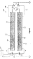
図1を参照すると、概略図において、1組の四重極ロッド120が図示されており、そこで双極性補助AC信号が、ロッドの対の1つに提供され得る。具体的には、1組の四重極ロッド120は、一対のXロッド122と、一対のYロッド124とを含み、そこにRF電圧源126によってRF電圧を印加し(公知の方法で)、径方向のイオン閉じ込め構造を提供し得る。1組の四重極ロッド120の放出端は、放出端の放出電極に適切な電圧を供給することによって閉塞し得る。
Referring to FIG. 1, in the schematic diagram, a set of
RF電圧源126によってすべてのロッドに印加され得るRF電圧に加え、双極性補助信号が、AC電圧源128によって(公知の方法で)、Yロッド124には提供されずに、Xロッド122に提供され得る。
In addition to the RF voltage that can be applied to all rods by the
本発明のいくつかの態様によると、XロッドおよびYロッドに供給されるRF電圧は、四重極DC成分を含む。Xロッドに印加される四重極DC成分は、Yロッドに印加される四重極DC成分とは反対の極性である。図2から7に関連して以下にさらに詳述されるように、XロッドおよびYロッドに印加される四重極DCは、電流量がロッドの長さに従って変化し得るような方法で印加される。別の場合には、XロッドおよびYロッドに印加される四重極DCは、ロッドの長さに従って一定にしてもよい。 According to some aspects of the invention, the RF voltage supplied to the X and Y rods includes a quadrupole DC component. The quadrupole DC component applied to the X rod has the opposite polarity to the quadrupole DC component applied to the Y rod. As described in further detail below in connection with FIGS. 2-7, the quadrupole DC applied to the X and Y rods is applied in such a way that the amount of current can vary according to the length of the rod. The In other cases, the quadrupole DC applied to the X and Y rods may be constant according to the length of the rod.
具体的には、本発明のいくつかの態様によると、以下に図示および説明されるように、ロッドセット内のロッドペアに従って提供される四重極DC分布は、ロッドセットの導入端での最大量からロッドセットの放出端での最小量へ線形的に低減する一方、ロッドセット内の別のロッドペアに印加される四重極DC分布は、ロッドセットの導入端での最小量からロッドセットの放出端での最大量へ線形的に増加する。本発明のこのような態様においては、1組の四重極ロッドの両方のロッドペアに印加される四重極DC成分は、このような四重極DC電圧の両方を単にゼロと等しくすることによって、ロッドセットの長さに従って一定となり得る。 Specifically, according to some aspects of the present invention, as shown and described below, the quadrupole DC distribution provided according to the rod pair in the rod set is the maximum amount at the introduction end of the rod set. The quadrupole DC distribution applied to another rod pair in the rod set is linearly reduced from the minimum amount at the lead end of the rod set to the minimum amount at the discharge end of the rod set. Increases linearly to the maximum amount at the edge. In this aspect of the invention, the quadrupole DC component applied to both rod pairs of a set of quadrupole rods is simply by making both such quadrupole DC voltages equal to zero. , Can be constant according to the length of the rod set.
図4から7に関連して以下に説明される本発明の他の態様によると、数組のセグメント化されたロッドが提供される。このような数組のセグメント化されたロッドのいくつかの場合において、数組のロッドに印加される四重極DC電圧は、必ずしもゼロにせずに、ロッドの長さに従って一様にしてもよい。 According to other aspects of the invention described below in connection with FIGS. 4-7, several sets of segmented rods are provided. In some cases of such a set of segmented rods, the quadrupole DC voltage applied to the sets of rods may not be zero, but may be uniform according to the length of the rod. .
ロッドに印加されたDC四重極電圧内の線形変化によって生じる導出された軸方向の力は、四重極DCの電位への寄与を考慮して、1組の線形四重極ロッドの二次元的中央部に対し計算され得る。終端効果は考慮されない線形イオントラップの中心部分では、二次元的四重極電位は、以下の式で表され得る。 The derived axial force caused by the linear change in the DC quadrupole voltage applied to the rod is a two-dimensional of a set of linear quadrupole rods, taking into account the contribution to the quadrupole DC potential. It can be calculated for the central part. In the central part of the linear ion trap where the termination effect is not taken into account, the two-dimensional quadrupole potential can be expressed as:

![]()
![]()
本例では、交流RFの項については考慮せず、四重極DCが最大量である軸方向位置から測定された、軸方向座標zの線形関数としてDC寄与を書き込んでもよく、以下の式で表される。 In this example, the AC RF term is not considered, and the DC contribution may be written as a linear function of the axial coordinate z, measured from the axial position where the quadrupole DC is the maximum amount. expressed.
議論を容易にするため、イオンは正であり、X極ロッドに印加される四重極DCの極性も正と仮定する。本議論は、同様に適用され、イオンの極性が負の場合にX極ロッドに印加される四重極DCの極性は負となる。 For ease of discussion, it is assumed that the ions are positive and the polarity of the quadrupole DC applied to the X pole rod is also positive. This discussion applies in the same way, and when the polarity of the ions is negative, the polarity of the quadrupole DC applied to the X pole rod is negative.
図2を参照すると、概略図において、本発明の第1の態様によるイオンガイド218が図示される。簡潔にするため、図2に対し図1の説明を繰り返して行わない。代わりに、明確にするために、図1に関連して上述された類似要素は、同一参照番号に100を加えて使用することで指定される。 Referring to FIG. 2, in a schematic diagram, an ion guide 218 according to a first aspect of the present invention is illustrated. For brevity, the description of FIG. 1 is not repeated with respect to FIG. Instead, for clarity, the similar elements described above in connection with FIG. 1 are designated by using the same reference number plus 100.
図2に示されるように、四重極DC電圧Ua1は、イオンガイド218の導入端218aでXロッド222に印加され、放出四重極DC電圧Ua2は、イオンガイド218の放出端218bでXロッド222に供給され得る。同様に、導入四重極DC電圧Ub1は、イオンガイド218の導入端218aでYロッド224に供給される一方で、放出四重極DC電圧Ub2は、イオンガイド218の放出端218bでYロッド224に供給され得る。四重極DC電圧Ua1、Ua2、Ub1およびUb2はすべて、コントローラ240によって制御される。
As shown in FIG. 2, the quadrupole DC voltage Ua1 is applied to the
図2では、導入電極S1および放出電極S2は図示されていない。電極S1およびS2は、導入および放出障壁を提供されるために使用され得る。以下に詳述するように、4つの四重極ロッドは、セグメント化されたロッドとして作製されるか、または、軸に沿って線形電圧勾配を提供するために半導体被覆を採用してもよい。軸方向加速様式の間、ロッドペアによって生成された軸方向場は、別のロッドペアによって生成された領域を解消し、軸近傍のイオンが軸方向に射出される強大な力に遭遇しないようにする。しかしながら、別のロッドペアよりもロッドの対の1つにより近くなるように励起されたイオンは、軸方向の一方向に射出される領域に遭遇し、それに応じて加速される。このような励起されたイオンが長手方向の十分なエネルギを捉えると、軸方向加速様式は解除され得る。次いで、イオンガイド218の放出端218bの放出障壁S2上の小電圧が、放出端218bへ加速されるイオンを除くトラップ内のすべてのイオンを維持するために使用され得る。 In FIG. 2, the introduction electrode S1 and the emission electrode S2 are not shown. Electrodes S1 and S2 can be used to provide an entrance and exit barrier. As described in detail below, the four quadrupole rods may be made as segmented rods or employ a semiconductor coating to provide a linear voltage gradient along the axis. During the axial acceleration mode, the axial field generated by a rod pair eliminates the area generated by another rod pair and prevents ions near the axis from encountering a powerful force that is ejected in the axial direction. However, ions that are excited to be closer to one of the pair of rods than another pair of rods encounter a region that is ejected in one axial direction and are accelerated accordingly. If such excited ions capture sufficient energy in the longitudinal direction, the axial acceleration mode can be released. The small voltage on the emission barrier S2 at the emission end 218b of the ion guide 218 can then be used to maintain all ions in the trap except for ions that are accelerated to the emission end 218b.
選択的軸方向への質量の輸送のための軸方向加速場を押し出す上述の方法は、以下のステップを伴う。第1のステップでは、複数の着目前駆イオンが捕捉され、分離され得る。本ステップでは、Ua1をUa2と等しく、Ub1をUb2と等しくし、軸方向加速場が提供されないようにされ得る。いくつかの実施形態では、Ua1=Ua2=Ub1=Ub2である。同様に、イオンガイドの導入端218aまたは放出端218bからのイオンの逃避を防止するために、S1およびS2は、Ua1よりも大きくすることができ、いくつかの実施形態では実際に大きい。本ステップでは、FNF(Filtered Noise Field)法またはSWIFT(Stored Waveform Inverse Fourier Transforms)法を使用して、着目前駆イオンを分離することが可能である。別様に、RFおよびDCを切り替えることによって(Ua1=Ua2≠Ub1=Ub2となるように)、高および低質量フィルタを使用して、着目前駆イオンを選別することができる。
The above-described method of extruding an axial acceleration field for selective axial mass transport involves the following steps. In the first step, a plurality of precursor ions of interest can be captured and separated. In this step, Ua1 can be equal to Ua2, Ub1 can be equal to Ub2, and no axial acceleration field can be provided. In some embodiments, Ua1 = Ua2 = Ub1 = Ub2. Similarly, S1 and S2 can be larger than Ua1 and are actually larger in some embodiments to prevent escape of ions from the ion
ステップ2では、最小質量/電荷(m/z)を有する前駆イオンが、双極性励起電圧227(同様に、コントローラ240によって制御される)を使用して励起され得る。再び、着目選択イオンを径方向に励起する本ステップの間、Ua1=Ub1およびUa2=Ub2となる。同様に、長手方向にイオンを含むように、S1およびS2は両方Ua1よりも大きくなる。
In
ステップ3では、軸方向加速様式が使用され、ステップ2で励起されたイオンをイオンガイド218の放出端218bへ加速される。上述のように、本ステップでは、Ua1はUa2と等しくはなく、Ub1はUb2と等しくないため、イオンガイド218に沿った非ゼロ四重極DC電圧勾配を、中心軸から径方向に変位するイオンに作用する導出された軸方向の力(式4による)に生じさせるようにする。イオンは軸周辺で振動しているため、イオンに作用する平均的軸方向場は、以下のように表され得る。
In step 3, an axial acceleration mode is used to accelerate the ions excited in
本発明のいくつかの態様によると、Ua1=Ub2およびUb1=Ua2である。例えば、Ua1およびUb2は両方+5ボルトである一方、Ub1およびUa2は両方−5ボルトであってもよい。このような電圧構造は望ましく、トラップ内に格納されたイオンの質量範囲を拡大するために有利となる低DC電圧を維持することができる。本軸方向加速ステップでは、S1およびS2は、Ua1よりも大きいままであり、イオンガイド218内に軸方向に捕捉されたイオンを維持するために依然として重要である。さらに、本軸方向加速ステップは、励起されたイオンが十分な軸方向エネルギを得て、ステップ4のS2を通過するための十分な時間の間継続されなければならない。加速場のスイッチが入れられた場合に励起されたイオンがごくわずかな速度を有していると仮定すると、時間間隔T後の軸方向の速度は、以下のようになる。
According to some aspects of the invention, Ua1 = Ub2 and Ub1 = Ua2. For example, Ua1 and Ub2 may both be +5 volts, while Ub1 and Ua2 may both be -5 volts. Such a voltage structure is desirable and can maintain a low DC voltage that is advantageous for expanding the mass range of ions stored in the trap. In this axial acceleration step, S1 and S2 remain larger than Ua1, and are still important for maintaining ions trapped in the ion guide 218 in the axial direction. Furthermore, this axial acceleration step must be continued for a sufficient time for the excited ions to obtain sufficient axial energy and pass through S2 of
軸方向放出ステップ4に続いて、ステップ2から4を、ステップ1で分離された他の着目前駆イオンに対し繰り替えることができる。連続して高質量のこのような前駆イオンをステップ2で提供された同一周波数の双極性補助信号と共振させるために、RF電圧の振幅を増加させることが可能である。別様に、補助信号の周波数が新しい着目前駆イオンのそれぞれの運動周波数と一致させるために再調整され得る間、RF電圧振幅は維持することができる。ステップ1で最初に選択されたすべてのイオンの処理後、ステップ1から5を、新しいイオン群を使用して繰り替えることが可能である。随意に、イオンは、異なる順番で選択的に放出される質量であってもよい。例えば、ステップ2では、最大のm/zを有する前駆イオンは、双極性励起電圧227を使用して励起され、続いてステップ3および4を使用して放出され得る。次いで、RF電圧の振幅を連続して低減させ、低質量のイオンを低振幅双極性補助信号と共振させることができる。別様に、異なる順番で異なるm/zのイオンを励起するサイクルの間、RF電圧を増減させることができる。
Following the
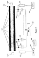
図3を参照すると、概略図において、本発明の別の態様によるイオンガイド318が図示される。簡潔にするために、図3に対し図2の説明は繰り返されない。明確にするために、図2と関連して上述された類似要素は、同一参照番号に100を加えて指定される。
Referring to FIG. 3, in a schematic diagram, an
図3に示されるように、Xロッド322およびYロッド324の両方が、高誘電絶縁層332で被覆され得る。いくつかの実施形態では、このような絶縁層332は最低10ボルトDCを分離することが可能である。それによって、このような絶縁層332は、抵抗薄膜330で被覆され得る。いくつかの実施形態では、このような抵抗薄膜330は、1Ωから100MΩのそれぞれのロッド上に終端間抵抗を提供する。好ましくは、抵抗被膜330および絶縁層332の両方が可能な限り薄いことが望ましい。
As shown in FIG. 3, both the
図3に示すように、四重極DCは、変化DC四重極電圧源328aおよび328bのそれぞれによって、Xロッド322およびYロッド324の一端に印加され得る。変化DC四重極電圧源328aおよび328bによって提供されるDC四重極電圧は、反対の極性である。変化DC四重極電圧源328aおよび328bは、後述するように、コントローラ340によって制御され得る。また、コントローラ340は、Xロッド322およびYロッド324の少なくとも一方に双極性励起電圧を制御自在に加え得る。電圧源328aおよび328bと電位差計331との接地接続は、RF供給源326によって供給されるRF電圧上に載置可能である。このような配列が電気的視点からより複雑であったとしても、ロッド322、324と導電被膜330との間にRF電位差はないため、絶縁層332に対する要件は緩和する。本構造の付加的利点は、導電被膜に供給されるRFおよびDC電圧を源結合する必要がないため、導電被膜が1オームまでの低抵抗を有すること可能であることである。
As shown in FIG. 3, quadrupole DC may be applied to one end of
本発明の態様に従うと、図3のイオンガイド318を、パルス四重極DCを用いて質量の選択的軸方向輸送に使用することができる。まず、第1の複数のイオン群がイオンガイド318の導入端に導入される。この複数のイオン群内のそれぞれのイオン群は、異なるm/zを有する。RF閉じ込め場は、公知の方法でXロッド322とYロッド324との間に提供され、ロッドセット内にこの第1の複数のイオン群を径方向に閉じ込め得る。ユーザ/オペレータは、第1の複数のイオン群内の第1のイオン群に対し第1の質量対電荷比(m/z)を選択することができる。次いで、ユーザは、コントローラ340を操作し、双極性励起電圧を使用して第1の径方向励起場を提供することができる。このような第1の径方向励起場は、中心長手軸から第1の選択された質量/電荷範囲を有する第1のイオン群を変位させる。同時に、第1の選択された質量/電荷範囲から離れた第2の質量/電荷範囲を有する第2のイオン群は、励起された第1のイオン群よりもイオンガイド318の中心長手軸の近くに保持される。これは、第1のイオン群を双極性電気信号と共鳴させるために、RF手段の第1のRF振幅を選択することによって行われ得る。
In accordance with aspects of the present invention, the
第1のイオン群が径方向に励起された後、軸方向加速場が提供され、第1のイオン群に作用する第1の軸方向の力を提供する。軸方向加速場は、DC四重極電圧源328aおよび328bをそれぞれ使用して、第1の四重極DC電圧をXロッド322に、第2の四重極DC電圧をYロッド324に提供することによって提供される可能性があり、いくつかの実施形態では実際に提供される。第1の四重極DC電圧は、第2の四重極DC電圧に対し反対の極性である。第1および第2の四重極DC電圧の両方が、抵抗被膜330に提供される。抵抗被膜330の終端間抵抗によって、Xロッド322およびYロッド324の長さに従って第1の四重極DC電圧および第2の四重極DC電圧の両方の電位における低減が生じる。その結果、第1の四重極DC電圧および第2の四重極電圧によって提供される軸方向加速場は、ロッドセットの長さに従って生成される。これは、上述のように、第1のイオン群に作用する第1の軸方向の力を提供する。随意に、抵抗被膜330をロッドの一部のみに沿って提供し、軸方向加速場がロッドセットの長さのこの部分のみに従って変化するようにしてもよい。抵抗被膜330の抵抗が実質的に一様であると仮定すると、第1および第2の四重極DC電圧は、イオンガイド318の長さに従って線形的に変化し、第1のイオン群に作用する一定の軸方向の力を生成する。
After the first group of ions is excited in the radial direction , an axial acceleration field is provided to provide a first axial force acting on the first group of ions. The axial acceleration field provides a first quadrupole DC voltage to the
上述のように、軸方向加速場は、十分なモーメントを第1のイオン群に与えるに十分な時間維持され、この第1のイオン群をイオンガイド318の放出端に提供される放出障壁場を通過して軸方向に放出する。同時に、放出障壁場は、放出端からの第2のイオン群の軸方向放出を妨げるのに十分である。
As described above, the axial acceleration field is maintained for a time sufficient to impart a sufficient moment to the first group of ions, and the emission barrier field provided at the discharge end of the
いくつかの実施形態では、軸方向加速場によって径方向励起場の効果が歪められ得るため、軸方向加速場は径方向励起場と同時に提供されず、わずかに異なるm/zのイオンがイオンガイド318の長さに沿った異なる地点で径方向に励起されるようにする。故に、第1のイオン群がイオンガイド318内で径方向に励起されている間、第1および第2の四重極DC電圧が排除され、四重極DC勾配がイオンガイド318の長さに沿って提供されないようにされ得る。その結果、この軸方向加速場から導出された軸方向の力は、第1のイオン群の径方向励起の間提供されない。いくつかの実施形態では、径方向励起場は、軸方向加速場が提供される間も遮断される。これは、双極性励起電圧を単に遮断することによって行われ得る。
In some embodiments, the effect of the radial excitation field can be distorted by the axial acceleration field, so that the axial acceleration field is not provided simultaneously with the radial excitation field and slightly different m / z ions are ion guides. Be excited radially at different points along the length of 318. Thus, while the first group of ions is excited radially in the
図3に記載される複数組のロッドは、あらゆる方法で構成されてもよい。例えば、所望の最終半径よりも半径において0.003”小さいステンレス製ロッドは、約0.010”厚のアルミナ層で被覆してもよい。続いて、ロッドを所望の半径に機械加工し、0.003”厚のアルミナ層としてもよい。次いで、アルミナで被覆されたロッドをマスク加工し、抵抗被膜330を塗布する。抵抗被膜330は非常に薄いため、恐らく厚さ10ミクロン以下となり得るため、抵抗被膜330の厚さは、ロッドの半径長に著しい影響を及ぼす必要がない。最後に、金属帯をロッド322および324のそれぞれの端部に適用し、一端の変化DC四重極電圧源328aおよび328bからのリード線と、他端のリード線329との良好なオーム接触を促進する。
The plurality of sets of rods described in FIG. 3 may be configured in any manner. For example, a stainless steel rod 0.003 "smaller in radius than the desired final radius may be coated with an alumina layer about 0.010" thick. Subsequently, the rod may be machined to the desired radius to provide a 0.003 "thick alumina layer. The rod coated with alumina is then masked and a
別様かつより単純に、既に標準仕様に機械加工された通常のステンレス製ロッド322および324は、高誘電ポリマー(抵抗被膜330)で被覆し、10ミクロンの層が100ボルトDCにも絶えうるように十分な抵抗性を有してもよい。続いて、わずか数ミクロンの深さまでイオンをポリマー層内に注入し、抵抗被膜330を生成する。上述のように、端部の金属帯によって、抵抗被膜330と、一端の変化DC四重極電圧源328aおよび328bからのリード線と、他端のリード線329との間の良好なオーム接触が確保される。
Alternatively and more simply, conventional
図3のロッドセットを作製する第3の方法は、平均的深さ23μmまでの[2,2]−パラシクロファンパラリン([2,2]−para−cyclophane paralyne)からの絶縁層の化学蒸着(CVD)を伴い、続いて、推定約0.5μmの厚さの水素化アモルファスシリコン(a−Si:H)膜の抵抗被膜の化学蒸着が行われる。 A third method of making the rod set of FIG. 3 involves chemical vapor deposition of insulating layers from [2,2] -paracyclophaneparaline up to an average depth of 23 μm. (CVD) followed by chemical vapor deposition of a resistive film of a hydrogenated amorphous silicon (a-Si: H) film with an estimated thickness of about 0.5 μm.
図4を参照すると、概略図において、本発明の第3の態様によるイオンガイド420が図示される。簡潔にするために、図4に対し図3の説明は繰り返されない。明確にするために、図3に関連して上述された類似要素は、同一参照番号に100を加えた番号を使用して指定される。
Referring to FIG. 4, in a schematic diagram, an
イオンガイド420は、複数のセグメント425に分割される。イオンガイド420の放出端は、図4の右側に位置する。放出電極427aは導入電極427bが導入端に提供される一方で、イオンガイド420の放出端に提供される。同一のRF電圧をイオンガイドのそれぞれのセグメントに印加し、イオンビームを径方向に閉じ込めることができる。複数のセグメント425のそれぞれのセグメントに対し、個別の電圧(例えば、i番目のセグメントにはUi)をRF電圧に付加し得る。それぞれの電圧Uiは、個別に選択され、四重極DC成分電圧を含み、すべての四重極DC電圧が一緒になって、イオンガイド420の軸に沿って所望の分布を提供することを可能にする。例えば、図示されるように、個別の電圧U1およびU2は、独立して制御可能な電源PS1およびPS2によって、そのそれぞれのセグメントに供給される。
The
それぞれの個別の電源PSiは、付随するレジスタ426および付随するコンデンサ428を含み、コントローラ440によって制御される。レジスタ426は、そのそれぞれのセグメントに印加される特定の四重極DC電圧の決定に主に関与する一方、コンデンサ428は、そのそれぞれのセグメントに提供されるAC電圧の決定に主に関与する。このようにして、異なるDCおよびAC電圧をイオンガイド420の異なるセグメントに印加してもよい。故に、例えば、PS1によって第1のセグメントに提供される四重極DCは、PS2によって第2のセグメントに供給される四重極DC電圧をわずかに上回ってもよく、それによって、PS3(図示せず)によって第3のセグメントに供給されるDC四重極電圧をわずかに上回ってもよい。このようにして、提供される全体の四重極DC電圧分布は、ステップ関数によって表されてもよく、四重極DC電圧は、イオンガイド420の複数のセグメント425におけるそれぞれのセグメント上で一定に維持され、次いで新しいセグメントで異なる四重極DC電圧に突然変更される。しかしながら、イオンガイドの軸に沿った複数のセグメント425のそれぞれのセグメントの寸法が可能な限り小さく作製される場合、このステップ関数は直線に近似し、軸方向座標zに対する微分によって、軸方向に一様になるように近似する力をもたらされ得るようにすることができる。
Each individual power supply PSi includes an associated
概して、それぞれの個別のセグメントに印加される電圧Ui(t)は、図示されるように、時間の関数であり得る。具体的には、Uiの四重極DC成分は、時間の関数であり得る。故に、例えば、複数の着目前駆イオンが捕捉され、分離される第1のステップと、双極性励起を使用して選択された前駆イオンが励起される第2のステップの両方において、同一四重極DC電圧を複数のセグメント425のそれぞれのセグメントに印加し、前駆イオンのいずれかに作用する導出された軸方向の力が存在しないようにすることができる。次いで、ステップ3では、異なる四重極DC電圧が、複数のセグメント425のそれぞれのセグメントに印加され得る。結果として生じる四重極DC電圧勾配は、ステップ2で励起され、それによってロッドの対の1つへ変位された前駆イオンに作用する導出された軸方向の力を生成し、その導出された軸方向の力は、放出されたイオンを放出端へ押し出す。次いで、ステップ4では、同一四重極DC電圧が、複数のセグメント425のすべてのセグメントに再び印加される。
In general, the voltage Ui (t) applied to each individual segment can be a function of time, as shown. Specifically, the quadrupole DC component of Ui can be a function of time. Thus, for example, in both a first step where a plurality of precursor ions of interest are captured and separated and a second step where a precursor ion selected using bipolar excitation is excited, the same quadruple. A polar DC voltage may be applied to each segment of the plurality of
図5を参照すると、概略図において、本発明の第4の態様によるイオンガイド520が図示される。明確にするために、同一参照番号に100を加えた番号を使用して、図4に関連して上述された類似要素を指定する。しかしながら、簡潔にするために、図4の説明は、図5に対し繰り返されない。
Referring to FIG. 5, in a schematic diagram, an
図5のイオンガイド520に印加される四重極DC電圧分布は、電源522、終端レジスタ529およびセグメント間レジスタ526によって決定される。電源522は、コントローラ540によって制御される。セグメント間レジスタ526は、四重極DC電圧分布が単一DC電源522のみによって供給されることが可能なように使用される。四重極DC電圧分布は、イオンガイド520の複数のセグメント525間で、セグメント間レジスタ526の抵抗に基づいて変化する。すべてのレジスタが同一抵抗を有し、複数のセグメント525のすべてのセグメントが同一寸法を有する場合、複数のセグメント525に印加される四重極DC電圧は、イオンガイド520の長さに従って、セグメント毎に一様に変化する。
The quadrupole DC voltage distribution applied to the
単一RF/AC電圧源524は、複数のセグメント525のそれぞれのセグメントに、コンデンサ528を介してRF/AC電圧を提供する。それぞれのコンデンサ528が適切な電気容量を有すると仮定すると、同一のRF/AC電圧がそれぞれのセグメントに印加される。
A single RF /
上述のように、操作の第1の数段階の間、四重極DC電圧源手段522は、いくつかの実施形態では、イオンガイド520の長さに従って四重極DC電圧勾配を提供しない。換言すると、いくつかの実施形態では、複数の着目前駆イオンが、イオンガイド520の導入端に導入され、径方向にイオンを含むためのRF場をロッドに提供するRF/AC電圧源525によって捕捉されている間、DC四重極電圧勾配は、イオンガイド520の長さに従って提供されないが、好適な放出および導入障壁電圧は、放出および導入電極527aと527bのそれぞれに提供され、軸方向にイオンを含む。イオンガイド520の長さに従って四重極DC電圧が一定となる結果、導出された軸方向の力は、捕捉されたイオンに作用しない。次いで、選択されたm/zを有する選択前駆イオン群が励起され、それによってロッドの対の1つに変位された後、四重極DC電圧源手段522を作動させ、四重極DC電圧をイオンガイド520の複数のセグメント525に供給することができる。セグメント間レジスタ526によって、印加される四重極DC電圧は、セグメント毎に変化し、それによって励起されたイオンに作用する導出された軸方向の力を生成する。励起されたイオンが十分にこの導出された軸方向の力によって加速された後、DC電圧源手段522を再び解除し、四重極DC電圧をイオンガイド520の長さに従って一定になるようにすることができる。次いで、放出電極527aに提供される放出障壁電圧S2を、すべてのロッドに供給されるDC電圧よりもわずかに高くなるまで低減させ、励起されていないイオンを保持しながら、励起されたイオンが放出障壁を通過するようにすることができる。
As mentioned above, during the first few stages of operation, the quadrupole DC voltage source means 522 does not provide a quadrupole DC voltage gradient according to the length of the
図5のイオンガイド520では、四重極DC電圧分布は、レジスタ526の抵抗に基づいて、複数のセグメント525間で変化する。故に、この電圧分布の形状は、典型的には、レジスタ526の抵抗によって定義される。しかしながら、ある場合には、四重極DC電圧分布をより容易に変化させることが望ましい。
In the
図6を参照すると、概略図において、本発明の第5の態様によるイオンガイド620が図示される。明確にするために、同一参照番号に100を加えた番号を使用して、図5に関連して上述された類似要素を指定する。しかしながら、簡潔にするために、図5の説明は、図6に対して繰り返されない。
Referring to FIG. 6, in a schematic diagram, an
図6では、単一RF/AC電源624は、コンデンサ628を介して、イオンガイド620の複数のセグメント625内のそれぞれのセグメントに連結される。この場合、イオンガイド620に提供されるRF/AC電圧分布の形状は、コンデンサ628の値によって予め決定されるが、当然ながら、このようなAC電圧分布の振幅は、AC電源624によって変更され得る。対照的に、独立して制御可能な個別のDC電源は、複数のセグメント625のそれぞれのセグメントに対して提供される。それぞれのDC電源は、コントローラ640によって制御される。このような個別の電源のそれぞれは、レジスタ626によって付随するセグメントに接続される。この場合、イオンガイド620に従って提供されるDC電圧分布は、それぞれのセグメントに対する個別のDC電源を独立して制御することによって変化し得る。
In FIG. 6, a single RF /
図6のイオンガイド620によって、四重極DC電圧分布は、図5のイオンガイド520の場合よりも容易に制御することが可能となるが、これはより複雑となることを犠牲にして達成される。つまり、複数のセグメント625のそれぞれのセグメントに対し独立した制御可能DC電源を提供する。対照的に、図5のイオンガイド520は、単一DC電源522および単一RF/AC電源524のみを必要とする。
The
図7を参照すると、概略図において、本発明の第6の態様によるイオンガイド720が図示される。明確にするために、同一参照番号に100を加えた番号を使用して、図6に関連して上述された類似要素を指定する。しかしながら、簡潔にするために、図6の説明は、図7に対し繰り返されない。
Referring to FIG. 7, in a schematic diagram, an
図7のイオンガイド720は、RF/AC電圧および四重極DC電圧の複数のセグメント725内のそれぞれのセグメントへの提供に関与する、単一電源721のみ含む。つまり、図7に図示されるように、電源721は、複数のセグメント725の最初と最後のセグメントに直接連結される。最初と最後のセグメントとの間の中間セグメントは、容量分圧器728によってRFパスに沿って結合され、電源721によって供給されるRF電圧は、これらの容量分圧器728を介してこのような個別のセグメントに供給される。このような容量分圧器728の電気容量は、イオンガイド720の長さに従ってRF電圧分布を定義する。理想的には、容量分圧器728の電気容量は、十分に大きくなるように選択され、RF電圧がロッドの長さを超えて著しく低減しないようにする。しかしながら、いくつかの用途では、容量分圧器728の電気容量を増加または変化させることによって、ロッドの長さに従って四重極RFの振幅を変化させることが望ましい。
The
四重極DC電圧は、電源手段721によって、最初と最後のセグメントに直接提供される。最初と最後のセグメントとの間の中間セグメントは、レジスタ726によってDCパスに沿って結合され、電源721によって供給されるDC電圧は、これらのレジスタ726を介して個別のセグメントに供給される。レジスタ726の抵抗は、イオンガイド720の長さに従って、四重極DC電圧分布を定義する。図5に関連して上述したように、一様な四重極DC分布は、供給される四重極DC電圧をゼロボルトと単に等しくすることによって、イオンガイド720の長さに従って提供され得る。
The quadrupole DC voltage is provided directly by the power supply means 721 to the first and last segments. The intermediate segments between the first and last segment are coupled along the DC path by
図7では、図3から6と同様に、DCおよびRFパスが交差して示されているが、このようなパスは、実際には互いに分離されるべきであることは、当業者には理解されるであろう。 In FIG. 7, as in FIGS. 3-6, the DC and RF paths are shown crossed, but those skilled in the art understand that such paths should actually be separated from each other. Will be done.
図8を参照すると、フローチャートにおいて、本発明の態様によるイオンの分離方法が示される。図8におけるフローチャートのステップ802では、イオンは、ロッドセットの導入端に導入される。次いで、ステップ804では、ロッドセットの放出端に隣接するロッドセットの放出電極に放出手段を生成し、ロッドセットにイオンを径方向に閉じ込めるためのロッドセットのロッドとの間にRF手段を生成することによって、ロッドセット内にイオンを捕捉される。また、ステップ804は、十分な圧力の緩衝ガスを捕捉場内に提供することによって一般的に達成される衝突冷却および集束を含むことができる。ステップ806では、イオンを少なくとも2つの異なるイオン群に分離するための質量対電荷比が選択される。典型的には、選択される質量対電荷比は、前駆イオンのうちの最小質量対電荷比となる。ステップ808では、選択された前駆イオンが、上述のような励起電圧を使用して、径方向次元内で励起される。励起場は、双極性成分、四重極成分、または他の好適な成分、およびそれらの重ね合わせを有することができる。本発明のいくつかの態様によると、それぞれのステップ802、804、806および808の間、四重極DC電圧勾配が、ロッドセットに全くまたは殆ど提供されず、四重極DC成分場、あるいは特に軸方向加速場が、概して提供されないようにする。
Referring to FIG. 8, a flowchart illustrates a method for separating ions according to an embodiment of the present invention. In
次いで、ステップ810では、軸方向加速場が提供される。いくつかの実施形態では、双極子励起場は、本軸方向加速場が提供される前に解除される。また、いくつかの実施形態では、軸方向加速場は、四重極DC電圧勾配をロッドセットに提供することによって提供され、四重極DC電圧勾配が導出された軸方向の力を生じさせる。
Then, in
双極子励起場がステップ808で提供されると、ロッドセット内のイオンは、ロッドセットの中心軸から外側へ径方向に移動する第1のイオン群と、励起されず、故に中心軸の周辺に群集したままである第2のイオン群とに分割される。ステップ810では、軸方向加速場または導出された軸方向の力が、第2のイオン群よりも第1のイオン群に非常に大きく作用し、この第1のイオン群をロッドセットの放出端へ加速させる。
When a dipole excitation field is provided in
ステップ812では、放出障壁電圧を十分に低減させ、第1のイオン群が、ステップ810のロッドセットの放出端へ加速され、同時に第2のイオン群を保持するに十分な強固さを維持したまま、放出障壁を通過することを可能にさせる。ステップ814では、軸方向放出後、第1のイオン群は、さらに処理され得る。これは、単に検出によるものであってもよく、別様に、例えば、断片化等のさらなる処理ステップを伴ってもよい。続いて、ステップ816では、第2のイオン群は、ステップ818におけるさらなる処理のために軸方向に放出されてもよい。第2のイオン群のこのような軸方向放出は、第1のイオン群のために採用された方法と実質的に同一方法で進められるであろう。つまり、初めに、上述のような双極性励起電圧を使用して、RF場のRF振幅を変更することによって、第2のイオン群が励起され、第2のイオン群が双極性励起電圧と共振するようにする。再び、上述のように、本発明のいくつかの態様では、この第2のイオン群が励起されている間、四重極DC電圧勾配は、ロッドセットに全くまたは殆ど提供されない。続いて、軸方向加速場が提供され、第2のイオン群を放出障壁へ射出され得る。次いで、ステップ812のように、放出障壁電圧が十分に低減され、第2のイオン群を、他の非加速イオンを保持しながら、放出障壁を通過させることができる。続いて、異なるm/zの付加的イオン群を、類似方法で放出することが可能である。
In
図9を参照すると、ブロック図において、さらに別の本発明の態様によるタンデム質量分析計の配列900が図示される。タンデム質量分析計の配列900は、イオン源902を含み、図3から7のいずれかのイオンガイド等の質量選択的放出トラップ904にイオンを放出する。イオン源902は、任意の好適なイオン源であり得る。例えば、エレクトロスプレーイオン化(ESI)源、またはマトリックス支援レーザー脱離イオン化(MALDI)源、あるいは電子衝撃(El)源等である。イオン源は、イオンの継続的ストリームまたはイオンのパルスストリームを提供することが可能である。図8に関連して上述したように、イオンは、質量選択的放出トラップ904内に捕捉される。便利な操作様式の1つは、イオン源がイオンのストリームを生成し、そのパルスが軸方向放出トラップの操作サイクルと同期する場合である。この場合、イオン源によって生成されるイオンは、軸方向放出トラップ内に蓄積され、処理され得る。一方、イオン源が継続的イオンストリームまたは非同期パルスイオンストリームを生成する場合、トラップは、一定の間開放され、イオンを蓄積させ、さらなる処理ステップの間にさらにイオンが流入しないように、その後閉鎖させることができる。処理ステップの間の流入イオンの損失を回避するために、付加的蓄積イオントラップを軸方向放出トラップの上流に載置することができる。蓄積トラップは、軸方向放出トラップが閉鎖されても、イオンの蓄積を継続することが可能である。次いで、蓄積されたイオンは、イオンを受容する準備ができると、軸方向放出トラップに送出される。イオン蓄積間隔の時間およびイオンビームの強度によって、トラップ内に収集されるイオン数が制御される。この数は、一定の制限以下に維持され、トラップの操作における空間電荷効果が影響を受けることを回避するべきである。この制限は、トラップの空間電荷容量と称される場合がある。従って、ビーム強度が高い場合、イオンの一部のみ導入し、残りは拒否し、空間電荷容量制限内のイオン数を維持する必要がある。そのような場合、イオンの利用を向上させる一方法として、イオンストリームを選別し、着目イオンのみ保持する方法がある。従って、着目以外のイオンを格納するために、空間電荷容量が無駄にされることがない。これは、例えば、Filtered Noise Filter(FNF)またはSimulated Waveform Inverse
Fourier Transform(SWIFT)技術を適用して、蓄積ステップの間に達成され得る。イオン源からのイオンが直接軸方向放出トラップへ向かう場合、蓄積の間に選別を適用するための適切な電子機器を、軸方向放出トラップに接続することができる。蓄積トラップが軸方向放出トラップの前に使用される場合は、蓄積トラップ内のイオンの選別により有利となり、対応する選別電子機器を蓄積トラップに付設すべきである。
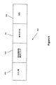
Referring to FIG. 9, in a block diagram, an
Applying Fourier Transform (SWIFT) technology can be achieved during the accumulation step. If ions from the ion source are directed directly to the axial emission trap, suitable electronics for applying sorting during accumulation can be connected to the axial emission trap. If the storage trap is used before the axial emission trap, it is advantageous to sort the ions in the storage trap, and the corresponding sorting electronics should be attached to the storage trap.
トラップ904が充満すると、選択された質量対電荷比のうちから特定のイオン群が選択される。再び、図8に関連して上述したように、このイオン群は、初めに、双極子励起場に曝され、中心軸から径方向に移動する。異なるm/zの他のイオンは、同時に中心軸のより近くに保持される。次いで、四重極DC電圧勾配がロッドセットに提供され、それによって、導出された軸方向の力が生じ、励起されたイオン群が質量選択的放出トラップ904の放出端へ射出される。十分なモーメントがこの選択されたイオン群に提供され、質量選択的放出トラップ904の放出端で障壁を通過し、そこから断片化セル906へ入ることが可能となる。断片化セル906では、選択されたイオン群は断片化され、次いで、軸方向に放出され、質量分析計908内で検出を受け得る。断片化セル906からの第1の選択されたイオン群のフラグメントの放出に続いて、第2の選択されたイオン群が、第1の選択されたイオン群に対し上述された同一方法で、次の断片化および質量分析計908による下流検出のために、質量の選択的トラップ904から断片化セル906へ軸方向に放出され得る。
When the trap 904 is full, a specific group of ions is selected from the selected mass to charge ratio. Again, as described above in connection with FIG. 8, this group of ions is initially exposed to a dipole excitation field and moves radially from the central axis. Other ions of different m / z are held closer to the central axis at the same time. A quadrupole DC voltage gradient is then provided to the rod set, thereby producing a derived axial force, and the excited ions are ejected to the emission end of the mass selective emission trap 904. Sufficient moment is provided for this selected group of ions, allowing the mass selective emission trap 904 to pass through the barrier at the emission end and enter the fragmentation cell 906 therefrom. In the fragmentation cell 906, the selected ions are fragmented and then released axially and can be detected in the
図10を参照すると、概略図において、本発明の第9の態様による線形イオントラップ質量分析計システム1000が図示される。質量分析計システム1000は、4つの細長いロッドの組Q0、T1、T2およびQ2を含み、ロッドセットQ0の後にオリフィス板IQ1、ロッドセットT2の前にIQ2、ロッドの組T2とQ2との間にIQ3、ロッドセットQ2の後にIQ4を有する。短くて太いロッドの付加的組ST1およびST2が、オリフィス板IQ1とロッドセットT1との間、およびロッドセットT1とオリフィス板IQ2との間にそれぞれ提供される。異なる本発明の態様に従って、ロッドセットT1は、図3から7のいずれかのロッドの組または図8の方法の質量の選択的軸方向輸送を実施するために好適な他のロッドセットであってもよい。
Referring to FIG. 10, a schematic diagram illustrates a linear ion trap
イオン源からのイオンは、Q0で冷却されてもよく、いくつかの実施形態では実際に冷却され、約8x10⁻²トルの圧力で維持されてもよく、いくつかの実施形態では実際に維持される。短くて太いロッドST1は、オリフィス板IQ1とロッドセットT1との間に提供され、イオンの流れをロッドセットT1に集束する。いくつかの実施形態では、T1は、長さ10cmあり、約200万の単独で電荷されたイオンの空間電荷容量を有してもよい。T1の圧力は、3x10⁻⁵トルで維持され得る。いくつかの実施形態では、T1は、100msの冷却および分離間隔と前駆イオンにつき1サイクル5msの質量の選択的放出サイクルで動作可能である。例えば、20の前駆イオンが選択される場合、100msのサイクルである。いくつかの実施形態では、T1は、20前駆イオンと仮定すると稼働率5Hzを有してもよく、Q2からの最大平均イオン電流は、約10Mイオン/秒となる。 Ions from the ion source may be cooled at Q0, actually cooled in some embodiments, maintained at a pressure of about 8 × 10 −2 Torr, and actually maintained in some embodiments. The A short and thick rod ST1 is provided between the orifice plate IQ1 and the rod set T1 to focus the ion flow onto the rod set T1. In some embodiments, T1 may be 10 cm long and have a space charge capacity of about 2 million singly charged ions. The pressure of T1 can be maintained at 3 × 10 −5 torr. In some embodiments, T1 is capable of operating with a 100 ms cooling and separation interval and a selective ejection cycle with a mass of 5 ms per precursor ion per cycle. For example, if 20 precursor ions are selected, the cycle is 100 ms. In some embodiments, T1 may have a utilization of 5 Hz assuming 20 precursor ions, and the maximum average ion current from Q2 will be about 10 M ions / second.
ロッドセットT1内では、着目前駆イオンが、ノッチFNFまたはSWIFT励起を使用して分離されることができ、いくつかの実施形態では実際に分離される。別様に、四重極RFおよびDC選別、または両方の組み合わせ、あるいは他の好適な方法を使用して、着目前駆イオンを分離してもよい。続いて、イオンは、T1から、ST2、IQ2、T2およびIQ3を通ってQ2へ軸方向に放出されることができ、いくつかの実施形態では実際に放出される。IQ2は、T1からイオンビームを収容するための大きな楕円形のオリフィスを有する。T2は、励起されたイオンの径方向エネルギの衝突減衰のために使用され得る。さらに、CIDのための高エネルギを達成するための便宜的方法を提供し得る。T2でイオンが捕捉されると、T2のオフセット電圧が所望のレベルまで上昇され得る。T2内に格納されたイオンは、放出障壁(IQ3)が低減し、衝突セルにイオンが放出するまで、そのまま保持される。イオンの軸方向速度は、T2とQ2との間の電位差によって決定される。T2は高RF電圧で動作するため、高オフセット電圧に容易に耐え得る。一方、Q2のオフセット電圧は、質量分析計の後続の段階における制約のため、制限され得る。例えば、Q2が直角注入飛行時間(Time−of−Flight;TOF)計器に結合される場合、Q2オフセット電圧は、TOF質量分析計の他のパラメータに固定および連結され得る。別様に、T2オフセット電圧は、Q2オフセット電圧が低減され、所望の衝突エネルギを得る間、固定電位に維持され得る。捕捉障壁(IQ4)は、イオンがQ2を離れるのを防止するために使用され得る。イオンが断片化し定着すると、Q2のオフセットが、所望のレベルへもたらされ得る。そこでようやく、IQ4障壁が開放され、イオンを計器の後続の段階へ進め、所望のQ2オフセット電位で開始され得る。このような操作の様式は、例えばMALDIによって生成される高質量イオンのように、軸方向エネルギのより高いレベルがCIDに必要な場合、有益である。 Within rod set T1, the precursor ions of interest can be separated using notch FNF or SWIFT excitation, and in some embodiments are actually separated. Alternatively, the precursor ions of interest may be separated using quadrupole RF and DC sorting, or a combination of both, or other suitable methods. Subsequently, ions can be released axially from T1, through ST2, IQ2, T2 and IQ3 to Q2, and in some embodiments are actually released. IQ2 has a large elliptical orifice to accommodate the ion beam from T1. T2 can be used for collisional attenuation of the radial energy of the excited ions. Furthermore, a convenient method for achieving high energy for CID may be provided. As ions are trapped at T2, the offset voltage of T2 can be raised to a desired level. The ions stored in T2 are held until the emission barrier (IQ3) is reduced and ions are released into the collision cell. The axial velocity of the ions is determined by the potential difference between T2 and Q2. Since T2 operates at a high RF voltage, it can easily withstand a high offset voltage. On the other hand, the offset voltage of Q2 can be limited due to constraints in subsequent stages of the mass spectrometer. For example, if Q2 is coupled to a Time-of-Flight (TOF) instrument, the Q2 offset voltage can be fixed and coupled to other parameters of the TOF mass spectrometer. Alternatively, the T2 offset voltage can be maintained at a fixed potential while the Q2 offset voltage is reduced to obtain the desired collision energy. A trapping barrier (IQ4) can be used to prevent ions from leaving Q2. As ions fragment and settle, Q2 offsets can be brought to the desired level. Finally, the IQ4 barrier is opened and ions can be advanced to subsequent stages of the instrument, starting at the desired Q2 offset potential. Such a mode of operation is beneficial when higher levels of axial energy are required for the CID, such as high mass ions generated by MALDI.
従って、T1とQ2との間の十分な電位差が、前駆イオンのCID断片化を確実にするために提供され得る。別様に、光開裂、イオン/中性衝突、電子捕獲/移動解離、またはイオン反応等の前駆イオンを変動する他の手段を使用してもよい。イオンがQ2内に入ると、好適な質量分析計によってさらに分析され得る。 Thus, a sufficient potential difference between T1 and Q2 can be provided to ensure CID fragmentation of the precursor ions. Alternatively, other means of varying the precursor ion may be used such as photocleavage, ion / neutral collisions, electron capture / transfer dissociation, or ion reactions. Once the ions enter Q2, they can be further analyzed by a suitable mass spectrometer.
続いて、フラグメントイオンは、Q2内に蓄積され、T1に戻され得る。フラグメントイオンがT1内に入ると、異なる種類のフラグメントイオンが、上述の方法で径方向励起場およびパルス軸方向加速場を使用して選択的に放出され、さらなる断片化のために軸方向に放出されQ2に戻される。次いで、着目イオンの各フラグメントのための断片化質量スペクトル記録を取得するために、さらに分析され得る。続いて、第2の着目フラグメントイオンが、上述のように径方向励起場およびパルス軸方向加速場を使用して、T1から軸方向に放出され得る。 Subsequently, the fragment ions can be accumulated in Q2 and returned to T1. As fragment ions enter T1, different types of fragment ions are selectively ejected using the radial excitation field and pulse axial acceleration field in the manner described above and ejected axially for further fragmentation. And returned to Q2. It can then be further analyzed to obtain a fragmentation mass spectral record for each fragment of the ion of interest. Subsequently, a second fragment ion of interest can be ejected axially from T1 using a radial excitation field and a pulsed axial acceleration field as described above.
本手段によって、特定の操作において1つのフラグメントのみ分離および断片化される代わりに、一群のフラグメントの断片化質量スペクトルを得ることができる。また、付加的質量分析計を含む装置において、さらなる断片化ステップによって、単一実行から得られることができる情報の増加につながり得る。操作の他の様式では、着目前駆イオンは、T1内で分離され、次いで断片化のためにQ2に直接送られる。フラグメントがQ2内で収集されると、T1に戻され、次いで図8の方法に従って連続的に処理され得る。故に、フラグメントイオンの1組の断片化質量スペクトルが収集され、MS3と称される情報を提供する。 By this means, instead of separating and fragmenting only one fragment in a particular operation, a fragmented mass spectrum of a group of fragments can be obtained. Also, in devices that include additional mass spectrometers, further fragmentation steps can lead to an increase in information that can be obtained from a single run. In another mode of operation, the precursor ions of interest are separated in T1 and then sent directly to Q2 for fragmentation. Once the fragments are collected in Q2, they can be returned to T1 and then processed sequentially according to the method of FIG. Thus, a set of fragmented mass spectra of fragment ions is collected and provides information referred to as MS 3 .
図11を参照すると、概略図において、本発明の第10の態様による線形イオントラップ質量分析計システム1100が図示される。簡潔にするために、図10の説明は、図11に対し繰り返されない。
Referring to FIG. 11, in a schematic diagram, a linear ion trap
図11の線形イオントラップ質量分析計システム1100は、図10の線形イオントラップ質量分析計1000に類似している。しかしながら、線形イオントラップ質量分析計システム1100は、付加的細長いロッドセットT3を含み、線形イオントラップ質量分析計システム1000内のT2の代わりとなる。質量分析計システム1100のT2は、質量分析計システム1000(図10)のT1に類似している。線形イオントラップ質量分析計システム1100では、複数の前駆イオンがT1内で分離され得る。次いで、T2がイオンの他の部分を質量選択的に放出している間、異なるRF電圧が、独立してT1およびT2に印加され、T1内で前駆イオンを格納および分離する。このような構成は、軸方向放出トラップ内の負荷サイクル損失を回避可能であるため、高強度継続的イオンビームと動作する場合は特に有益である。実際に、イオンが図10に示されるT1から質量選択的に放出される場合、T1への導入端は閉塞され、イオンはQ0内に収容され得る。しかし、イオン流動が多い場合、イオンがQ0の空間電荷容量にすぐに充満する。対照的に、図11に示される構成によって、T1内における着目イオンの継続的蓄積および分離を可能にする。T1内のイオンは分離され得る(つまり、望ましくないイオンは除去され得る)ため、空間電荷蓄積率を低減することができる。従って、T1は、T2内のすべての着目イオンを処理するために十分な時間の間、イオンを蓄積可能である。このようにして、図11の質量分析計システム1100は、継続的イオンビームを処理するために使用され得る一方、着目イオンの損失を低減する。
The linear ion trap
本発明の他の変形および改良が可能である。例えば、提供される四重極DC成分場の代わりに、他の好適な手段を採用し、質量分析計の中心軸からの変位に対してイオンに力を及ぼす軸方向加速場を提供してもよい。例えば、補助電極をロッドセットに加えてもよい。このような電極は、勾配をつけ(Loboda A,Krutchinsky A.,Loboda O.,McNabb J.,Spicer V.,Ens W.,Standing K.G.Eur.J.Mass Spectrom.2000;6:531参照)、軸方向場を生成することができる。このような電極に対向する対に反対の極性の電圧を印加することによって、軸方向場が軸近傍でゼロに維持され得る。同時に、軸方向場が軸から離れて非ゼロであるため、励起されたイオンは、正味軸方向加速を受けることになる。他の実施形態では、1組の主要ロッドによって生成された軸方向場は、補助電極によって生成された軸方向場によって反作用し、ロッドセットの中心の軸方向場がゼロに維持される一方、ロッドセットの中心から離れた軸方向場が非ゼロになるようにし、従って、高振幅または径方向振動を有するイオン群を加速することができる。そのような改良または変形のすべては、本願に添付の請求項によって定義される本発明の領域および範囲内であると考えられる。 Other variations and modifications of the invention are possible. For example, instead of the provided quadrupole DC component field, other suitable means may be employed to provide an axial acceleration field that exerts a force on the ions with respect to displacement from the central axis of the mass spectrometer. Good. For example, an auxiliary electrode may be added to the rod set. Such electrodes are provided with a gradient (Loboda A, Krutchinsky A., Loboda O., McNabb J., Spicker V., Ens W., Standing KG Eur. J. Mass Spectrom. 2000; 6: 531. See), and an axial field can be generated. By applying a voltage of opposite polarity to a pair facing such an electrode, the axial field can be maintained at zero near the axis. At the same time, since the axial field is non-zero away from the axis, the excited ions will undergo a net axial acceleration. In other embodiments, the axial field generated by a set of primary rods is counteracted by the axial field generated by the auxiliary electrode, while the axial field in the center of the rod set is maintained at zero while the rod The axial field away from the center of the set can be non-zero, and thus ions with high amplitude or radial oscillation can be accelerated. All such modifications or variations are considered to be within the scope and scope of the invention as defined by the claims appended hereto.
Claims (24)
前記方法は、
a)第1の複数のイオン群を前記ロッドセットの導入端へ導入するステップと、
b)前記複数のロッドの間に電界を生成し、前記第1の複数のイオン群を前記ロッドセット内に閉じ込めるステップと、
c)前記第1の複数のイオン群内の第1のイオン群に対する第1の質量/電荷範囲を選択するステップと、
d)第1の径方向励起場を提供し、前記中心長手軸から前記第1の質量/電荷範囲内の前記第1のイオン群を径方向に変位させ、同時に前記第1のイオン群よりも前記中心長手軸に近くに第2のイオン群を保持するステップであって、前記第2のイオン群は、前記第1の質量/電荷範囲から離れた第2の質量/電荷範囲内にあるステップと、
e)軸方向加速場を提供することによって、前記第1のイオン群に作用する第1の軸方向の力を提供するステップと
を含み、
前記第1の軸方向の力はステップd)の間には提供されない、方法。 A method of operating a mass spectrometer system having an elongated rod set, the rod set having an inlet end, an outlet end, a plurality of rods, and a central longitudinal axis;
The method
a) introducing a first plurality of ions into the introduction end of the rod set;
b) generating an electric field between the plurality of rods, and confining the first plurality of ions in the rod set;
c) selecting a first mass / charge range for a first group of ions in the first plurality of groups of ions;
d) providing a first radial excitation field, displacing the first group of ions within the first mass / charge range from the central longitudinal axis in a radial direction, and at the same time than the first group of ions; Holding a second group of ions close to the central longitudinal axis, wherein the second group of ions is in a second mass / charge range remote from the first mass / charge range. When,
e) providing a first axial force acting on the first group of ions by providing an axial acceleration field;
The method wherein the first axial force is not provided during step d).
前記軸方向加速場は、前記ロッドセットの長さの少なくとも一部に従って変化し、前記第1のイオン群に作用する前記第1の軸方向の力を提供する、請求項1に記載の方法。 The plurality of rods includes a first set of rods and a second set of rods, and step (e) provides a first DC voltage to the first set of rods; Providing the axial acceleration field by providing a DC voltage to the second set of rods, wherein the first DC voltage is opposite in polarity to the second DC voltage;
The method of claim 1, wherein the axial acceleration field varies according to at least a portion of the length of the rod set and provides the first axial force acting on the first group of ions.
ステップe)は、十分なモーメントを前記第1のイオン群に提供し、前記第1のイオン群が前記放出障壁を通過して押し出すステップを含む、請求項4に記載の方法。 Step b) comprises providing an emission barrier field at the emission end of the rod set and preventing axial emission of the second group of ions from the emission end;
The method of claim 4, wherein step e) comprises providing a sufficient moment to the first group of ions, the first group of ions pushing through the emission barrier.
g)前記軸方向加速場を提供し、前記第2のイオン群に作用する第2の軸方向の力を提供し、十分なモーメントを前記第2のイオン群に提供し、前記第2のイオン群を前記放出障壁を通過させ押し出すステップと
をさらに含み、
前記第2の軸方向の力はステップf)の間に提供されない、請求項5に記載の方法。 f) providing a second radial excitation field after pushing the first group of ions through the emission barrier and within the second mass / charge range from the central longitudinal axis; Displacing the group in the radial direction and simultaneously holding the third ion group closer to the central longitudinal axis than the second ion group, wherein the third ion group comprises the first mass Within a third mass / charge range remote from the charge range and the second mass / charge range;
g) providing the axial acceleration field, providing a second axial force acting on the second ion group, providing a sufficient moment to the second ion group, the second ion; And pushing the group through the release barrier,
6. A method according to claim 5, wherein the second axial force is not provided during step f).
ステップf)およびg)が異なる時間で生じることによって、前記第2の径方向励起場がステップg)の間に提供されない、請求項6に記載の方法。 By causing steps d) and e) to occur at different times, the first radial excitation field is not provided during step e),
7. The method of claim 6, wherein the second radial excitation field is not provided during step g) by causing steps f) and g) to occur at different times.
ステップ(e)の後に前記放出障壁を低減し、前記第1のイオン群の軸方向放出を促進するステップと、
前記第1のイオン群の軸方向放出後、前記放出障壁を増加させるステップと、
ステップ(g)の後、前記放出障壁を低減し、前記第2のイオン群の軸方向放出を促進するステップと、
前記第2のイオン群の軸方向放出後、前記放出障壁を増加させるステップと
をさらに含む、請求項6に記載の方法。 The method
Reducing the emission barrier after step (e) and promoting axial emission of the first group of ions;
Increasing the emission barrier after axial emission of the first group of ions;
After step (g), reducing the emission barrier and promoting axial emission of the second group of ions;
The method of claim 6 , further comprising: increasing the emission barrier after axial ejection of the second group of ions.
ステップe)で前記第1のイオン群を前記放出障壁を通過させ押し出した後、前記第1のイオン群を検出するステップと、
ステップg)で前記第2のイオン群を前記放出障壁を通過させ押し出した後、前記第2のイオン群を検出するステップと
をさらに含む、請求項7に記載の方法。 Prior to step a), separating a first precursor ion group from an ion sample, fragmenting the first precursor ion group, and providing the first plurality of ion groups;
Detecting the first ion group after pushing the first ion group through the emission barrier in step e); and
8. The method of claim 7, further comprising the step of detecting the second group of ions after pushing the second group of ions through the emission barrier in step g).
前記複数のロッドの間にRF場を提供し、前記ロッドセット内に前記第1の複数のイオン群を径方向に閉じ込めるステップと、
前記ロッドセットの前記放出端に放出障壁場を提供し、前記ロッドセットの前記導入端に導入障壁場を提供し、前記ロッドセット内に前記第1の複数のイオン群を軸方向に閉じ込めるステップと
を含む、請求項4に記載の方法。 Step (b)
Providing an RF field between the plurality of rods and radially confining the first plurality of ions within the rod set;
Providing an emission barrier field at the emission end of the rod set, providing an introduction barrier field at the introduction end of the rod set, and confining the first plurality of ions in the rod set in an axial direction; The method of claim 4 comprising:
a)イオン源と、
b)ロッドセットであって、前記ロッドセットは、長手軸に沿って延在する複数のロッドと、イオン源からイオンを導入するための導入端と、ロッドセットの長手軸を横断するイオンを放出する放出端とを有するロッドと、
c)前記ロッドセットの前記複数のロッドの間にRF場を生成する電圧源モジュールと、
d)径方向励起場を提供するための前記電圧源モジュールを制御するコントローラであって、i)操作の励起段階の間、中心長手軸から選択された質量/電荷範囲内にある第1のイオン群を径方向に変位させ、同時に前記第1のイオン群よりも前記中心長手軸の近くに第2のイオン群を保持し、前記第2のイオン群は、前記選択された質量/電荷範囲から離れた第2の質量/電荷範囲内にあり、次いでii)操作の軸方向加速段階の間、軸方向加速場を提供することによって前記第1のイオン群に作用する軸方向の力を提供するコントローラと
を含み、
前記コントローラは、前記操作の励起段階の間前記電圧源モジュールを制御して、前記軸方向加速場を遮断し、導出された軸方向の力が前記操作の励起段階で提供されないようにさらに動作可能である、質量分析計システム。 A mass spectrometer system comprising:
a) an ion source;
b) a rod set, said rod set emitting a plurality of rods extending along a longitudinal axis, an introduction end for introducing ions from an ion source, and ions traversing the longitudinal axis of the rod set A rod having a discharge end,
c) a voltage source module that generates an RF field between the plurality of rods of the rod set;
d) a controller that controls the voltage source module to provide a radial excitation field, i) a first ion in a mass / charge range selected from the central longitudinal axis during the excitation phase of operation. Displacing the group in the radial direction and simultaneously holding a second ion group closer to the central longitudinal axis than the first ion group, wherein the second ion group is from the selected mass / charge range Within the second mass / charge range away, and then ii) during the axial acceleration phase of operation, provide an axial force acting on the first group of ions by providing an axial acceleration field Including the controller and
The controller is further operable to control the voltage source module during the excitation phase of the operation to shut off the axial acceleration field so that no derived axial force is provided during the excitation phase of the operation. A mass spectrometer system.
前記ロッドセットの放出端に放出障壁場を提供し、前記放出端から前記第2のイオン群の軸方向放出を妨害し、
十分なモーメントを前記第1のイオン群に提供し、前記第1のイオン群を前記放出障壁を通過させ押し出すようにさらに動作可能である、請求項15に記載の質量分析計システム。 The controller controls the voltage source module;
Providing an emission barrier field at the emission end of the rod set, preventing axial emission of the second group of ions from the emission end;
16. The mass spectrometer system of claim 15, wherein the mass spectrometer system is further operable to provide a sufficient moment to the first group of ions and push the first group of ions through the emission barrier.
前記操作の軸方向加速段階後に前記放出障壁を低減し、前記第1のイオン群の軸方向放出を促進し、
前記第1のイオン群の軸方向放出後前記放出障壁を増加させ、前記第2のイオン群を保持するようにさらに動作可能である、請求項20に記載の質量分析計システム。 The controller controls the voltage source module;
Reducing the emission barrier after the axial acceleration phase of the operation, facilitating the axial emission of the first group of ions;
21. The mass spectrometer system of claim 20, wherein the mass spectrometer system is further operable to increase the emission barrier after axial emission of the first group of ions and retain the second group of ions.
Applications Claiming Priority (3)
| Application Number | Priority Date | Filing Date | Title |
|---|---|---|---|
| US74064005P | 2005-11-30 | 2005-11-30 | |
| US60/740,640 | 2005-11-30 | ||
| PCT/CA2006/001692 WO2007062498A1 (en) | 2005-11-30 | 2006-10-12 | Method and apparatus for mass selective axial transport using pulsed axial field |
Publications (3)
| Publication Number | Publication Date |
|---|---|
| JP2009517815A JP2009517815A (en) | 2009-04-30 |
| JP2009517815A5 JP2009517815A5 (en) | 2012-10-18 |
| JP5424085B2 true JP5424085B2 (en) | 2014-02-26 |
Family
ID=38091825
Family Applications (1)
| Application Number | Title | Priority Date | Filing Date |
|---|---|---|---|
| JP2008542568A Expired - Fee Related JP5424085B2 (en) | 2005-11-30 | 2006-10-12 | Method and apparatus for mass selective axial transport using a pulsed axial field |
Country Status (5)
| Country | Link |
|---|---|
| US (1) | US7459679B2 (en) |
| EP (1) | EP1955359B1 (en) |
| JP (1) | JP5424085B2 (en) |
| CA (1) | CA2626089C (en) |
| WO (1) | WO2007062498A1 (en) |
Families Citing this family (30)
| Publication number | Priority date | Publication date | Assignee | Title |
|---|---|---|---|---|
| US7456389B2 (en) * | 2006-07-11 | 2008-11-25 | Thermo Finnigan Llc | High throughput quadrupolar ion trap |
| US7633060B2 (en) * | 2007-04-24 | 2009-12-15 | Thermo Finnigan Llc | Separation and axial ejection of ions based on m/z ratio |
| WO2008154296A2 (en) * | 2007-06-11 | 2008-12-18 | Dana-Farber Cancer Institute, Inc. | Mass spectroscopy system and method including an excitation gate |
| GB0713590D0 (en) | 2007-07-12 | 2007-08-22 | Micromass Ltd | Mass spectrometer |
| GB2467466B (en) * | 2007-07-12 | 2010-12-29 | Micromass Ltd | Linear ion trap with radially dependent extraction |
| GB2461204B (en) * | 2007-07-12 | 2010-11-10 | Micromass Ltd | Linear ion trap with radially dependent extraction |
| GB0718468D0 (en) | 2007-09-21 | 2007-10-31 | Micromass Ltd | Mass spectrometer |
| GB0800526D0 (en) | 2008-01-11 | 2008-02-20 | Micromass Ltd | Mass spectrometer |
| CA2720249C (en) * | 2008-06-09 | 2015-12-08 | Dh Technologies Development Pte. Ltd. | A multipole ion guide for providing an axial electric field whose strength increases with radial position, and a method of operating a multipole ion guide having such an axial electric field |
| CA2720248C (en) * | 2008-06-09 | 2016-10-04 | Dh Technologies Development Pte. Ltd. | Method of operating tandem ion traps |
| US8101910B2 (en) * | 2008-10-01 | 2012-01-24 | Dh Technologies Development Pte. Ltd. | Method, system and apparatus for multiplexing ions in MSn mass spectrometry analysis |
| US20110204221A1 (en) * | 2008-10-14 | 2011-08-25 | Hiroyuki Satake | Mass spectrometer and method of mass spectrometry |
| DE102008055899B4 (en) * | 2008-11-05 | 2011-07-21 | Bruker Daltonik GmbH, 28359 | Linear ion trap as an ion reactor |
| WO2010135831A1 (en) * | 2009-05-27 | 2010-12-02 | Dh Technologies Development Pte. Ltd. | Linear ion trap for msms |
| CN102804367A (en) * | 2009-06-19 | 2012-11-28 | 道康宁公司 | Use of ionomeric silicone thermoplastic elastomers in electronic devices |
| WO2011057414A1 (en) * | 2009-11-16 | 2011-05-19 | Dh Technologies Development Pte. Ltd. | Apparatus and method for coupling rf and ac signals to provide power to a multipole in a mass spectrometer |
| US20110260048A1 (en) * | 2010-04-22 | 2011-10-27 | Wouters Eloy R | Ion Transfer Tube for a Mass Spectrometer Having a Resistive Tube Member and a Conductive Tube Member |
| US8680463B2 (en) * | 2010-08-04 | 2014-03-25 | Dh Technologies Development Pte. Ltd. | Linear ion trap for radial amplitude assisted transfer |
| JP5543912B2 (en) * | 2010-12-27 | 2014-07-09 | 日本電子株式会社 | Mass spectrometer |
| JP6541210B2 (en) | 2011-12-27 | 2019-07-10 | ディーエイチ テクノロジーズ デベロップメント プライベート リミテッド | Method of extracting ions with low M / Z ratio from ion trap |
| WO2013150351A1 (en) * | 2012-04-02 | 2013-10-10 | Dh Technologies Development Pte. Ltd. | Systems and methods for sequential windowed acquisition across a mass range using an ion trap |
| CN105684124B (en) * | 2013-10-16 | 2018-04-24 | Dh科技发展私人贸易有限公司 | Multiple precursor isolation for mass spectral analysis |
| EP3066682B1 (en) * | 2013-11-07 | 2021-03-31 | DH Technologies Development PTE. Ltd. | Multiplexing of ions for improved sensitivity |
| US9929002B2 (en) | 2013-12-19 | 2018-03-27 | Miromass Uk Limited | High pressure mass resolving ion guide with axial field |
| GB201322515D0 (en) * | 2013-12-19 | 2014-02-05 | Micromass Ltd | High pressure mass resolving ion guide with axial field |
| WO2015198721A1 (en) * | 2014-06-25 | 2015-12-30 | 株式会社 日立ハイテクノロジーズ | Mass spectrometer |
| US10410849B2 (en) | 2015-04-01 | 2019-09-10 | Dh Technologies Development Pte. Ltd. | Multipole ion guide |
| US10381213B2 (en) * | 2015-10-01 | 2019-08-13 | Dh Technologies Development Pte. Ltd. | Mass-selective axial ejection linear ion trap |
| US9899199B2 (en) * | 2016-06-30 | 2018-02-20 | Bruker Daltonics, Inc. | Mass spectrometer comprising a radio frequency ion guide having continuous electrodes |
| CN109065437B (en) * | 2018-08-03 | 2020-04-24 | 北京理工大学 | Ion resonance excitation operation method and device of quadrupole electric field and dipole electric field |
Family Cites Families (8)
| Publication number | Priority date | Publication date | Assignee | Title |
|---|---|---|---|---|
| CA2229070C (en) * | 1995-08-11 | 2007-01-30 | Mds Health Group Limited | Spectrometer with axial field |
| CA2256028C (en) * | 1996-06-06 | 2007-01-16 | Mds Inc. | Axial ejection in a multipole mass spectrometer |
| US6177668B1 (en) * | 1996-06-06 | 2001-01-23 | Mds Inc. | Axial ejection in a multipole mass spectrometer |
| US6504148B1 (en) * | 1999-05-27 | 2003-01-07 | Mds Inc. | Quadrupole mass spectrometer with ION traps to enhance sensitivity |
| US6630662B1 (en) * | 2002-04-24 | 2003-10-07 | Mds Inc. | Setup for mobility separation of ions implementing an ion guide with an axial field and counterflow of gas |
| US7071464B2 (en) * | 2003-03-21 | 2006-07-04 | Dana-Farber Cancer Institute, Inc. | Mass spectroscopy system |
| JP4690641B2 (en) * | 2003-07-28 | 2011-06-01 | 株式会社日立ハイテクノロジーズ | Mass spectrometer |
| JP4684287B2 (en) * | 2004-05-05 | 2011-05-18 | エムディーエス インコーポレイテッド ドゥーイング ビジネス アズ エムディーエス サイエックス | Method and apparatus for mass selective axial ejection |
-
2006
- 2006-10-12 EP EP06790847.5A patent/EP1955359B1/en not_active Not-in-force
- 2006-10-12 CA CA2626089A patent/CA2626089C/en not_active Expired - Fee Related
- 2006-10-12 WO PCT/CA2006/001692 patent/WO2007062498A1/en active Application Filing
- 2006-10-12 JP JP2008542568A patent/JP5424085B2/en not_active Expired - Fee Related
- 2006-11-13 US US11/558,952 patent/US7459679B2/en active Active
Also Published As
| Publication number | Publication date |
|---|---|
| EP1955359A1 (en) | 2008-08-13 |
| CA2626089C (en) | 2016-10-04 |
| EP1955359B1 (en) | 2015-04-01 |
| JP2009517815A (en) | 2009-04-30 |
| US7459679B2 (en) | 2008-12-02 |
| EP1955359A4 (en) | 2011-01-12 |
| CA2626089A1 (en) | 2007-06-07 |
| WO2007062498A1 (en) | 2007-06-07 |
| US20070120053A1 (en) | 2007-05-31 |
Similar Documents
| Publication | Publication Date | Title |
|---|---|---|
| JP5424085B2 (en) | Method and apparatus for mass selective axial transport using a pulsed axial field | |
| JP2009517815A5 (en) | ||
| US10043648B2 (en) | High duty cycle ion spectrometer | |
| US9287101B2 (en) | Targeted analysis for tandem mass spectrometry | |
| US20180090305A1 (en) | Ion Interface Device Having Multiple Confinement Cells and Methods of Use Thereof | |
| JP5001965B2 (en) | Mass spectrometer | |
| JP4738326B2 (en) | Tandem mass spectrometry data acquisition for multiple parent ion species in ion population | |
| US7858929B2 (en) | Ion energy spread reduction for mass spectrometer | |
| JP4654087B2 (en) | Mass spectrometer and mass spectrometry method | |
| US8637816B1 (en) | Systems and methods for MS-MS-analysis | |
| JP6541210B2 (en) | Method of extracting ions with low M / Z ratio from ion trap | |
| JP2009541967A (en) | Mass spectrometer | |
| GB2477007A (en) | Electrostatic trap mass spectrometer | |
| JP2002502086A (en) | Mass spectrometry from the surface | |
| JP2001307675A (en) | Mass spectroscope | |
| US11031232B1 (en) | Injection of ions into an ion storage device | |
| US11515138B2 (en) | Ion trapping scheme with improved mass range |
Legal Events
| Date | Code | Title | Description |
|---|---|---|---|
| A621 | Written request for application examination |
Free format text: JAPANESE INTERMEDIATE CODE: A621 Effective date: 20090917 |
|
| A521 | Written amendment |
Free format text: JAPANESE INTERMEDIATE CODE: A523 Effective date: 20100907 |
|
| A131 | Notification of reasons for refusal |
Free format text: JAPANESE INTERMEDIATE CODE: A131 Effective date: 20120306 |
|
| A601 | Written request for extension of time |
Free format text: JAPANESE INTERMEDIATE CODE: A601 Effective date: 20120605 |
|
| A601 | Written request for extension of time |
Free format text: JAPANESE INTERMEDIATE CODE: A601 Effective date: 20120606 |
|
| A602 | Written permission of extension of time |
Free format text: JAPANESE INTERMEDIATE CODE: A602 Effective date: 20120612 |
|
| A602 | Written permission of extension of time |
Free format text: JAPANESE INTERMEDIATE CODE: A602 Effective date: 20120613 |
|
| A524 | Written submission of copy of amendment under section 19 (pct) |
Free format text: JAPANESE INTERMEDIATE CODE: A524 Effective date: 20120903 |
|
| A131 | Notification of reasons for refusal |
Free format text: JAPANESE INTERMEDIATE CODE: A131 Effective date: 20130212 |
|
| A601 | Written request for extension of time |
Free format text: JAPANESE INTERMEDIATE CODE: A601 Effective date: 20130220 |
|
| A602 | Written permission of extension of time |
Free format text: JAPANESE INTERMEDIATE CODE: A602 Effective date: 20130227 |
|
| A521 | Written amendment |
Free format text: JAPANESE INTERMEDIATE CODE: A523 Effective date: 20130812 |
|
| A711 | Notification of change in applicant |
Free format text: JAPANESE INTERMEDIATE CODE: A712 Effective date: 20131009 |
|
| TRDD | Decision of grant or rejection written | ||
| A01 | Written decision to grant a patent or to grant a registration (utility model) |
Free format text: JAPANESE INTERMEDIATE CODE: A01 Effective date: 20131113 |
|
| A61 | First payment of annual fees (during grant procedure) |
Free format text: JAPANESE INTERMEDIATE CODE: A61 Effective date: 20131114 |
|
| R150 | Certificate of patent or registration of utility model |
Free format text: JAPANESE INTERMEDIATE CODE: R150 Ref document number: 5424085 Country of ref document: JP Free format text: JAPANESE INTERMEDIATE CODE: R150 |
|
| R250 | Receipt of annual fees |
Free format text: JAPANESE INTERMEDIATE CODE: R250 |
|
| R250 | Receipt of annual fees |
Free format text: JAPANESE INTERMEDIATE CODE: R250 |
|
| R250 | Receipt of annual fees |
Free format text: JAPANESE INTERMEDIATE CODE: R250 |
|
| R250 | Receipt of annual fees |
Free format text: JAPANESE INTERMEDIATE CODE: R250 |
|
| LAPS | Cancellation because of no payment of annual fees |