JP4654087B2 - Mass spectrometer and mass spectrometry method - Google Patents
Mass spectrometer and mass spectrometry method Download PDFInfo
- Publication number
- JP4654087B2 JP4654087B2 JP2005222327A JP2005222327A JP4654087B2 JP 4654087 B2 JP4654087 B2 JP 4654087B2 JP 2005222327 A JP2005222327 A JP 2005222327A JP 2005222327 A JP2005222327 A JP 2005222327A JP 4654087 B2 JP4654087 B2 JP 4654087B2
- Authority
- JP
- Japan
- Prior art keywords
- ion
- mass
- ions
- trap
- ion trap
- Prior art date
- Legal status (The legal status is an assumption and is not a legal conclusion. Google has not performed a legal analysis and makes no representation as to the accuracy of the status listed.)
- Expired - Fee Related
Links
Images


Classifications
-
- H—ELECTRICITY
- H01—ELECTRIC ELEMENTS
- H01J—ELECTRIC DISCHARGE TUBES OR DISCHARGE LAMPS
- H01J49/00—Particle spectrometers or separator tubes
- H01J49/0027—Methods for using particle spectrometers
-
- H—ELECTRICITY
- H01—ELECTRIC ELEMENTS
- H01J—ELECTRIC DISCHARGE TUBES OR DISCHARGE LAMPS
- H01J49/00—Particle spectrometers or separator tubes
- H01J49/26—Mass spectrometers or separator tubes
- H01J49/34—Dynamic spectrometers
- H01J49/42—Stability-of-path spectrometers, e.g. monopole, quadrupole, multipole, farvitrons
- H01J49/4205—Device types
- H01J49/422—Two-dimensional RF ion traps
- H01J49/4225—Multipole linear ion traps, e.g. quadrupoles, hexapoles
Description
本発明は、質量分析計に関する。 The present invention relates to a mass spectrometer.
プロテオーム解析などに用いられる質量分析計においては、多価イオンの選別が重要である。エレクトロスプレーイオン化では、ノイズイオンの多くが1価に帯電するのに対し、ペプチドイオンは多価に帯電する傾向がある。よって、多価イオンのみを効率よく1価イオンから分離する技術の重要性は高い。分解能が高くかつスペクトル重複が少ない場合は、電荷数情報は測定結果として得られる質量スペクトルを解析することにより得られる。ただし、前処理を簡便化した試料では多成分が混合し、スペクトル同士が重複して多価イオンおよび1価イオンのソフトウェアによる判別は難しい。このような課題に対し、特許文献1には価数分離をハードウェアで実現する方法について記述されている。ここでは、リニアトラップ内部において内部でのガス衝突によりイオンを室温に冷却する。その後、リニアトラップの端電極の片側もしくは両側のポテンシャルを下げていき、リニアトラップ部のオフセット電位に対し0.1〜1VのポテンシャルDに設定する。このとき1価イオンのトラップポテンシャルはDであるのに対し、n価イオンが感じるポテンシャルはnDとなる。一方、イオンの運動エネルギーは価数に依らずイオン冷却下ではほぼ室温エネルギー(kT)となる。イオンエネルギーはMaxwell Bolzmann広がりを持つため、多価イオンより低いポテンシャルを形成する低価数のイオンから順次トラップ外へ排出される。このようなプロセスを経た後、リニアトラップで質量分析を行う。または、飛行時間型質量分析部へイオン導入して質量分析を行う。また、この間に衝突ガス室などを設置してMS/MS分析などを行うことが記載されている。
In mass spectrometers used for proteome analysis and the like, selection of multiply charged ions is important. In electrospray ionization, most noise ions are charged monovalently, whereas peptide ions tend to be charged multivalently. Therefore, the importance of a technique for efficiently separating only multivalent ions from monovalent ions is high. When the resolution is high and the spectrum overlap is small, the charge number information can be obtained by analyzing a mass spectrum obtained as a measurement result. However, in a sample in which pretreatment is simplified, multiple components are mixed and spectra are overlapped, so that it is difficult to discriminate multivalent ions and monovalent ions by software. For such a problem,
リニアトラップでは、補助交流電圧を用いて質量電荷比(m/n, m:質量、n:電荷数)によるイオン分離が従来から広く行われている。これについては、特許文献2に記載されている。これによるとRF電圧により、径方向に調和ポテンシャルを形成する。この調和ポテンシャルに共鳴する補助交流電圧を向かい合った電極間に印加することにより径方向に特定の質量電荷比のイオンを排出する。
In a linear trap, ion separation based on a mass-to-charge ratio (m / n, m: mass, n: number of charges) has been conventionally performed using an auxiliary AC voltage. This is described in
リニアトラップにおける質量電荷比(m/n)に基づいたイオン分離の他の手法について、特許文献3に記載されている。これによるとRF電圧により、径方向に調和ポテンシャルを形成する。この調和ポテンシャルに共鳴する補助交流電圧を向かい合った電極間または、四重極ロッドと端電極間に印加することにより軸方向に特定の質量電荷比のイオンを排出する。
Another technique for ion separation based on the mass-to-charge ratio (m / n) in the linear trap is described in
リニアトラップにおける質量電荷比(m/n)に基づいたイオン分離の他の手法について、特許文献4に記載されている。多重極ロッド間に羽電極を挿入して軸上に調和ポテンシャルを形成する。この調和ポテンシャルに共鳴する補助交流電圧を羽電極間に印加することにより、軸方向に特定の質量電荷比のイオンを排出する。
Another technique for ion separation based on a mass-to-charge ratio (m / n) in a linear trap is described in
質量分析におけるイオンモビリティー分離は特許文献5に記載されている。イオン源またはイオントラップからパルス的に排出されたイオンが10mTorr程度のガス圧力下において一定のDC電界が印加される。電界により加速されるイオンの速度は異なるためイオンモビリティーの分離がDC電界による加速領域で行われる。イオンモビリティーにより質量分析部への到達タイミングが異なるため、分離が可能である。
Ion mobility separation in mass spectrometry is described in
ハードウェアによる価数分離の課題は高速化である。価数分離の時間、リニアトラップでは他の測定シーケンスが停止するため、装置全体でのイオンの利用効率(すなわち感度)が低下する問題がある。特許文献1による価数分離において高速な価数分離を行うには軸上のポテンシャル障壁を下げる必要がある。しかし、軸上のポテンシャルが小さくなると、フリンジングフィールドの影響から価数の選択性能が低下する。すなわち、(特許文献1)ではイオンの選択性と感度の両立が不可能であり、十分な価数分離性能を得るために数100msの分離時間を必要とする。イオン蓄積、電荷分離、排出の3シーケンスからなるか数分離トラップを例にイオン利用効率を算出する。一般には、イオンがイオン源から一定のレートで電荷分離トラップへと導入される。この場合、イオン蓄積時間TA、電荷分離時間TS、排出時間TEとするとイオンの利用効率は、(数1)であらわされる。
![]()
一方、(特許文献2)(特許文献3)(特許文献4)では質量電荷比による分離についてのみ記述されており、価数の分離については一切触れられていない。
本発明の課題は、リニアトラップを用いて高速の価数分離方法を提供することである。電荷分離時間が短くなれば数1から予想されるように、イオンのDuty Cycleが改善し感度が向上する。
The issue of hardware valence separation is speeding up. Since the valence separation time and other measurement sequences are stopped in the linear trap, there is a problem in that the use efficiency (that is, sensitivity) of ions in the entire apparatus is lowered. In order to perform high-speed valence separation in the valence separation according to
![]()
On the other hand, (Patent Document 2) (Patent Document 3) (Patent Document 4) describe only separation by mass-to-charge ratio, and do not mention valence separation at all.
An object of the present invention is to provide a high-speed valence separation method using a linear trap. If the charge separation time is shortened, as expected from
また、本発明が解決しようとするもう一つの課題は簡便な装置構成かつ高感度な装置を提供することである。特許文献5の方法では、高速なデータ処理系が必要となりコストが高い問題や、数10msのモビリティー分離中にイオンが拡散するため感度が著しく低下する問題がある。
Another problem to be solved by the present invention is to provide a simple apparatus configuration and a highly sensitive apparatus. In the method of
本発明の質量分析装置は、イオン源と、イオン源によりイオン化されたイオンをトラップするイオントラップと、イオントラップを構成する電極の電圧を制御するイオントラップ制御手段と、イオントラップから排出されたイオンを検出する検出器とを有する質量分析装置であって、イオントラップ制御手段は、電荷分離に用いる前記電圧の周波数と、第1の電荷を有する第1のイオンを前記イオントラップ外部へ排出し、第1の電荷より電荷数の少ない第2の電荷数を有する第2のイオン群をイオントラップ内部へ保持する前記電圧のゲイン値とについて質量電荷比毎のテーブルを有し、設定された質量電荷比に基づいて電圧を制御することを特徴とする。 The mass spectrometer of the present invention includes an ion source, an ion trap that traps ions ionized by the ion source, ion trap control means that controls the voltage of the electrodes that constitute the ion trap, and ions that are discharged from the ion trap. The ion trap control means discharges the frequency of the voltage used for charge separation and the first ions having the first charge to the outside of the ion trap, A mass charge-to-charge table having a table for each mass-to-charge ratio with respect to the voltage gain value for holding the second ion group having the second charge number smaller than the first charge in the ion trap; The voltage is controlled based on the ratio.
また、本発明の質量分析方法は、試料をイオン化する工程と、イオン化されたイオンをイオントラップ部に導入する工程と、イオントラップ部を構成する電極に対し、設定された質量電荷比に基づいた周波数と、第1の電荷を有する第1のイオンを前記イオントラップ外部へ排出し、第1の電荷より電荷数の少ない第2の電荷数を有する第2のイオンをイオントラップ内部へ保持する設定された質量電荷比におけるゲイン値を有する電圧を印加する工程と、排出された前記第1のイオンを検出する工程とを有することを特徴とする。 The mass spectrometric method of the present invention is based on the step of ionizing a sample, the step of introducing ionized ions into the ion trap portion, and the mass-to-charge ratio set for the electrodes constituting the ion trap portion. The frequency and the first ion having the first charge are discharged to the outside of the ion trap, and the second ion having the second charge number smaller than the first charge is held inside the ion trap. A step of applying a voltage having a gain value in the mass-to-charge ratio and a step of detecting the discharged first ions.
また本発明の質量分析装置は、イオン源と、前記イオン源によりイオン化されたイオンをトラップするイオントラップと、前記イオントラップを構成する電極の電圧を制御するイオントラップ制御手段と、前記イオントラップから排出されたイオンを検出する検出器とを有する質量分析装置であって、前記イオントラップ制御手段は、イオンモビリティー分離に用いる前記電圧の周波数と、第1のイオンモビリティーを有する第1のイオン群を前記イオントラップ外部へ排出し、第1のイオンモビリティーより小さい第2のイオンモビリティーを有する第2のイオン群をイオントラップ内部へ保持する前記電圧のゲイン値とについて質量電荷比毎のテーブルを有し、設定された質量電荷比に基づいて前記電圧ゲイン値または周波数を制御することを特徴とする。 The mass spectrometer of the present invention includes an ion source, an ion trap that traps ions ionized by the ion source, an ion trap control unit that controls a voltage of an electrode constituting the ion trap, and the ion trap. A mass spectrometer having a detector for detecting ejected ions, wherein the ion trap control means includes a frequency of the voltage used for ion mobility separation and a first ion group having first ion mobility. A table for each mass-to-charge ratio with respect to the gain value of the voltage that is discharged outside the ion trap and holds the second ion group having the second ion mobility smaller than the first ion mobility inside the ion trap; Control the voltage gain value or frequency based on the set mass to charge ratio And wherein the door.
また、本発明の質量分析方法は、試料をイオン化する工程と、イオン化されたイオンをイオントラップ部に導入する工程と、イオントラップ部を構成する電極に対し、第1のイオンモビリティーを有する第1のイオンをイオントラップ外部へ排出し、第1のイオンよりイオンモビリティーの小さい第2のイオンモビリティーを有する第2のイオンをイオントラップ内部へ保持する電圧を印加する工程と、排出された前記第1のイオンを検出する工程とを有することを特徴とする。 In addition, the mass spectrometry method of the present invention includes a step of ionizing a sample, a step of introducing ionized ions into the ion trap portion, and a first ion mobility having a first ion mobility with respect to the electrode constituting the ion trap portion. A voltage for holding the second ions having the second ion mobility smaller in ion mobility than the first ions inside the ion trap, and the discharged first ions And a step of detecting the ions.
本発明によれば、選択的に多価イオンを選択、透過可能なリニアトラップにより、高速で感度の高い分析装置・方法を提供できる。また、効率的なイオンモビリティーの分離が可能な、分析装置・方法を提供できる。 ADVANTAGE OF THE INVENTION According to this invention, a high-speed and highly sensitive analytical apparatus and method can be provided by the linear trap which can selectively select and permeate multivalent ions. In addition, it is possible to provide an analysis apparatus and method capable of efficient ion mobility separation.
図1は、本方式を適用した電荷分離を可能としたリニアトラップ部を使用した質量分析装置の構成図である。エレクトロスプレーイオン源やマトリックス支援レーザー脱離イオン化イオン源5で生成したイオンは、図示しない差動排気部やイオンガイド電極などを経て4本のロッド電極2と両端の端電極1,3より構成されるリニアトラップに導入される。
このリニアトラップへの電圧印加は制御部電源7により行われる。典型的にロッド電極2の長さを7.0mm、ポール径を7.0mm、ポール間距離を7.0mm、ロッド電極2と両端電極1,3間距離を10.0mm程度の形状を用いる。各ロッド電極2には一つおきに逆相のトラップRF電圧(周波数500〜3MHz(典型的には1MHz)、振幅100V〜5kV)が印加される。すなわち、2a,2c,および2b,2dには同位相の電圧が印加される。端電極にロッド電極のオフセット電位に対し1-5V程度の電圧を印加する。通常のリニアトラップの(ポール長さ)/(ポール間距離)の比率が5〜100程度であるのに対し、この値を3以下に設定することで端電極1,3のDC電界が内部へと浸透し、軸上に調和ポテンシャルを形成することが可能である。この直流電圧印加に伴い、ロッド電極2および端電極1、3により囲まれた空間内のz軸方向に調和ポテンシャルが形成される。
FIG. 1 is a configuration diagram of a mass spectrometer using a linear trap unit that enables charge separation to which this method is applied. The ions generated by the electrospray ion source or the matrix-assisted laser desorption
The voltage application to the linear trap is performed by the control
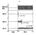
この調和ポテンシャルの中で特定の質量電荷比のイオンの軌道振幅が励起され、トラップ外へ排出するメカニズムについて以下説明する。測定シーケンスを図2に示す。測定シーケンスはイオン蓄積、冷却、分離排出、排除の4過程よりなる。イオン蓄積では、イオン源から生成されたイオンがイオントラップへ導入される。イオン源および差動排気の構成に依存するが、特に近年開発されたイオン導入効率が改善した差動排気部を用いるとスペースチャージを抑制するためイオンの蓄積時間は典型的には10ms以下に制限される。端電極1,3の電圧をいずれもロッド電極2のオフセット電位より数V〜数10V高く設定することにより、イオンをリニアトラップ内部にトラップする。次にイオン冷却が行われ、イオンは室温状態にまで冷却される。次にイオンの分離排出が行われる。ここでは以下に説明する方式により特定の質量電荷比のイオンのみが共鳴振幅し、トラップ外へと排出される。
分離排出時の調和ポテンシャルD0、調和ポテンシャルの極小部から端部までの距離をaとすれば、調和ポテンシャルの極小部からのZ方向の距離zにおける軸方向のポテンシャルは(数2)で近似される。
![]()
![]()
![]()
![]()
If the harmonic potential D 0 during separation and discharge is a and the distance from the minimum part to the end of the harmonic potential is a, the axial potential at the distance z in the Z direction from the minimum part of the harmonic potential is approximated by (Equation 2). Is done.
![]()
![]()
![]()
![]()
次に、上記リニアトラップを用いることにより電荷数nの分離を行う方法および原理について説明する。電荷分離を行う際の測定シーケンスは図2と同様である。測定シーケンスはイオン蓄積、冷却分離排出、排除の4過程よりなる。従来イオンモビリティーなどで測定された公知の衝突断面積データσ(nm2)は、分子量m(単位:Da)に対し、(数6)で近似される。
![]()
![]()
バッファーガスとしてヘリウム100mTorr(13Pa)とした場合の補助交流電圧に対するイオン排出率のシミュレーション結果を図4に示す。1価イオンは補助交流電圧4.3Vで完全に排出されるのに対し、2価、3価イオンではそれよりも低い補助交流電圧3.6V、3.4Vでそれぞれ100%排出されている。また、補助交流電圧を3.6Vに設定すると、1価イオンを100%トラップしながら2、3価イオンを100%トラップ軸方向へと排出することが可能である。
FIG. 4 shows a simulation result of the ion discharge rate with respect to the auxiliary AC voltage when the buffer gas is
トラップポテンシャル、ガス圧力をある値に設定したとき、価数分離に適した補助交流電圧は質量電荷比に依存する。予め、1価イオンを残し、多価イオンを排除するような補助交流圧電圧ゲインを幾つかの質量数に対して実験により求め、制御部電源7内部のゲインテーブル8に記録する。テーブルは、質量電荷比と電圧値との関係に関する情報であればよい。この実験用のサンプルとしては例えばポリエチレン重合体の混合物であるポリエチレングリコール500(以下PEG500)、PEG1000、PEG2000などの混合溶液を用いると良い。質量電荷比m/z500付近にはPEG500の1価イオン、PEG1000の2価イオン、PEG2000の4価イオンが存在する。質量電荷比m/z=500の電荷分離に用いる補助交流電圧の周波数は(数4)により算出される。この周波数の補助交流電圧ゲインを変化させる実験を行うことで、質量電荷比m/z=500付近での多価イオンのみを排出するような補助交流電圧値ゲインを求めることが可能である。また、質量電荷比m/z=1000付近ではPEG1000の1価イオンとPEG2000の2価イオンが存在する。同様にして(数4)より求められた周波数で補助交流電圧ゲインを調整する実験を行うことで、質量電荷比m/z=1000付近での多価イオンのみを排出するような電圧値ゲインを求めることが可能である。同様に各質量電荷比に対する周波数および電圧値ゲインを制御部電源7内のテーブル8に保存しておく。所望の質量電荷比の多価イオンを排出する場合には、制御部電源7内のテーブル8に保存した周波数、および電圧値ゲインを参照し補助交流電圧を決定する。
When the trap potential and gas pressure are set to certain values, the auxiliary AC voltage suitable for valence separation depends on the mass-to-charge ratio. In advance, auxiliary AC voltage gains that leave monovalent ions and exclude multivalent ions are experimentally obtained for several mass numbers, and are recorded in the gain table 8 inside the control
これにより、従来技術では不可能であった5msの短時間で価数により特定質量電荷比600においてイオン分離を行うことが可能である。典型的な蓄積時間10ms、電荷分離時間5msを(数1)に代入すると、Duty Cycleは50%となる。これは、従来方式の8%に比べ6倍の感度向上になる。これが本発明による価数分離の高速化の与える効果である。
n価とm価の分離能力(m>n)を定量的に判断するため、(数7)で表される指標Fを導入した。
![]()
In order to quantitatively determine the separation capacity (m> n) of n-value and m-value, the index F represented by (Expression 7) was introduced.
![]()
また、窒素(分子量28.0)、エアー(平均分子量28.8)、Ar(分子量40.0)のような高質量のバッファーガスを用いればほぼ質量に反比例し、更に低圧下(10〜15mTorr以上、1.3〜1.8Pa以上)で同様の現象は確認できる。価数分離が有効な上記の圧力領域は、通常のイオントラップ、リニアトラップの使用圧力(ヘリウムの場合で0.02〜10mTorr、2.6mPa〜1.3Pa)とは異なる。通常のイオントラップ、リニアトラップの使用圧力として上記の圧力(ヘリウム100mTorr以上、13Pa以上)を選択しない理由は、補助交流電圧を用いた質量電荷比における選択分解能が著しく低下するためであるが、本発明の課題は質量電荷比(分子量/電荷)の分離でなく電荷分離であるため、このような質量電荷比選択の分解能の低下は問題ない。以上説明したように、ヘリウム100mTorr以上(13Pa以上)、窒素(分子量28.0)、エアー(平均分子量28.8)、Ar(分子量40.0)のような高質量のバッファーガスを用いれば10〜15mTorr以上(1.3〜1.8Pa)において先に述べたのと同様な方法で適当な質量電荷比に対応した補助交流電圧の周波数および電圧値のゲインテーブル8を作成することにより、価数の大きなイオンのみを排出し、より価数の低いイオンをトラップすることによる電荷分離が可能である。
In addition, if a high-mass buffer gas such as nitrogen (molecular weight 28.0), air (average molecular weight 28.8), Ar (molecular weight 40.0) is used, it is almost inversely proportional to the mass, and further under low pressure (10 to 15 mTorr or more, 1.3 to 1.8 Pa) The above can confirm the same phenomenon. The above pressure region where valence separation is effective is different from the working pressure of a normal ion trap or linear trap (in the case of helium, 0.02 to 10 mTorr, 2.6 mPa to 1.3 Pa). The reason why the above pressure (
排出された価数の高いイオンは公知であるイオントラップ、リニアトラップ、TOF、フーリエ変換型イオンサイクロトロン質量分析部などの質量分析部6で検出される。また、排出された質量分析部6の公知の測定制御によりイオン選択、解離などの後に検出される場合もある。なお、本実施例の電荷分離リニアトラップにおいてロッド電極は4本であるが、6本、8本、12本などであっても以上の効果については同様である。また、トラップ内に蓄積された価数の低いイオンについても、排除する前にトラップにDC電場を印加することにより質量分析部6へ導入して検出することも可能である。蓄積時間10ms、排出時間5msとすると、Duty Cycleは50%となり、従来方式の8%に比べ6倍の感度向上になる。これが本発明による価数分離の高速化の与える効果である。
The discharged high-valence ions are detected by a
また、上記実施例では特定範囲の質量電荷比の価数分離を行うため、単一周波数の補助交流電圧を用いた。実施例2では、同時に広い質量電荷比での電荷分離を可能とする。(数8)に示すような周波数fN(典型的には0.5kHzごと、1〜50kHz)の合成波を補助交流電圧として用いる。
![]()
![]()
実施例3では実施例1で説明した電荷分離トラップを特にイオン源と質量分析部の中間部(差動排気部)に利用した応用例を図6に示す。
エレクトロスプレーイオン源、大気圧化学イオン源、大気圧光イオン源、大気圧マトリックス支援レーザー脱離イオン源などの大気圧イオン源101で生成されたイオンは第1細孔レンズ102を経て第1差動排気部103に導入される。第1差動排気部は真空ポンプ(図示せず)で排気され、1〜10Torr(130〜1300Pa、主成分はエアー)で維持されている。第2細孔レンズ104を通過して、本発明のトラップが配置される第2差動排気部105にイオンは導入される。真空ポンプ(図示せず)により10mTorr〜1Torr(1.3〜130Pa、主成分エアー)の圧力に維持された第2差動排気部105にはイオンをトラップするプレトラップトラップ部(106、107)と価数分離を行う価数分離トラップ部(108、109、110)が設置される。プレトラップ部はマルチポールロッド電極106と端電極107からなる。マルチポールロッド電極間には交互に逆位相のRF電圧(500-2000kHz、最大振幅1kV)が印加され、径方向のトラップポテンシャルを形成する。
In the third embodiment, FIG. 6 shows an application example in which the charge separation trap described in the first embodiment is used particularly in an intermediate portion (differential exhaust section) between the ion source and the mass analysis section.
Ions generated by an atmospheric
また端電極107にDC電圧をコントロールすることにより、軸方向のトラップポテンシャルも形成可能であり、これによりイオンをプレトラップ内部にトラップ、排出することが可能である。価数分離トラップについては実施例1で述べたのと同様である。プレトラップ部、価数分離トラップ部は各々プレトラップ制御電源120、価数分離トラップ部電源121により制御され、それらはコントローラ122により制御される。プレトラップ部および価数分離トラップ部の測定シーケンスを図7に示す。シーケンスは蓄積、冷却、分離排出、排除の4シーケンスからなる。蓄積時にはプレトラップの端電極107のDC電圧がプレトラップのロッド電極DC電圧より低く設定される。これにより、プレトラップされていたイオンやイオン源から導入されたイオンが電荷分離トラップへと導入される。その後、1ms程度イオンクーリングを行った後、補助交流電圧を印加して電荷分離が行われる。この際、高価数のイオンが端電極110を通過して質量分析室111へと導入される。質量分析室111は、真空ポンプにより排気され10-4Torr(0.013Pa)以下の圧力に維持される。排出されたイオンは質量分析室に配置されたイオントラップ、リニアトラップ、TOFなど様々な質量分析計で検出される。
Further, by controlling the DC voltage at the
また、選択、解離などの後に検出される場合もある。イオン排出を行った後に価数分離トラップに残留した低価数のイオンについてはRF電圧を0にすることで、トラップ外へ排除することができる。このような動作を繰り返し行うことにより、これ以後の質量分析部には選択的に多価イオンが導入される。また、高速で測定が行われるため電荷分離によるDuty Cycleの低下は大幅に低減できる。本実施例ではイオン排出時および電荷分離時にイオン源から導入されたイオンはプレトラップ部においてトラップしておくため、(数1)の関係が成り立たなくなる。プレトラップされたイオンは蓄積時にリニアトラップへ導入されるのでDuty Cycleは100%となる。これは従来方式の8%に比べ12倍の感度向上になる。これが本発明による価数分離の高速化の与える効果である。 It may also be detected after selection, dissociation, and the like. Low valence ions remaining in the valence separation trap after ion ejection can be excluded from the trap by setting the RF voltage to zero. By repeating such an operation, multivalent ions are selectively introduced into the subsequent mass analysis units. Moreover, since the measurement is performed at high speed, the decrease in duty cycle due to charge separation can be greatly reduced. In this embodiment, the ions introduced from the ion source at the time of ion ejection and charge separation are trapped in the pre-trap part, so the relationship of (Equation 1) does not hold. Since the pre-trapped ions are introduced into the linear trap during accumulation, the duty cycle is 100%. This is 12 times the sensitivity improvement compared to 8% of the conventional method. This is the effect of speeding up the valence separation according to the present invention.
各実施例について共通するが、本発明の効果は本実施例で挙げた形状のリニアトラップ以外(特許文献2,3,4に記したもの)でも効果を有する。すなわちイオントラップにおいて、直流電圧または交流電圧において軸方向または径方向に実質的な調和ポテンシャルを形成し、そのポテンシャル内でイオンの共鳴周波数に共鳴する補助交流電圧を印加することにより、高価数のイオン軌道振幅が選択的に低価数のイオン軌道振幅より大きくなることを利用して価数分離を行う方式全般についてこの特許の効果は及ぶ。また、本発明に付随する効果として特定の価数のイオンのみが選択的に透過可能であるため、その後の質量分析部においてスペースチャージを低減できるなどの効果もある。
Although common to each embodiment, the effect of the present invention is effective even in a shape other than the linear trap having the shape described in this embodiment (described in
以上の実施例では、価数の分離についてのみ記述したが、類似の原理を用いてイオンモビリティーによる分離を行うことも可能である。1mTorr以上のガス存在下で電界を印加すると、ガスとの衝突とつりあった速度でイオンが移動することが知られている。このときのイオン速度/電界を表す指標としてイオンモビリティーが用いられる。例えば、同じ質量数でもイオン形状が大きければ衝突頻度が高く、イオンモビリティーは小さくなる。第1のイオンのイオンモビリティーが第2のイオンモビリティーよりも小さいとは、同じ電界中においても加速されるイオンの速度が小さくなることをいい、特定速度以上のイオンが排出されるようなイオントラップが存在すれば、特定形状のイオンを分離することが可能である。 In the above embodiment, only the valence separation has been described, but it is also possible to perform separation by ion mobility using a similar principle. It is known that when an electric field is applied in the presence of a gas of 1 mTorr or more, ions move at a speed that matches the collision with the gas. Ion mobility is used as an index representing the ion velocity / electric field at this time. For example, if the ion shape is large even at the same mass number, the collision frequency is high and the ion mobility is low. The ion mobility of the first ion is smaller than that of the second ion mobility means that the speed of the accelerated ion is reduced even in the same electric field, and an ion trap that discharges ions at a specific speed or higher. Is present, it is possible to separate ions of a specific shape.
図8にイオンモビリティー分離を行う装置の一例を示す。イオン源200で生成されたイオンは、イオンガイドやイオントラップなどからなるイオン輸送部を通過した後、バッファーガス中にある入口側端電極201を通過し、イオントラップへと導入される。イオントラップは挿入電極としての羽電極(204、205)と、マルチポールロッド電極202より構成され、羽電極(204、205)とマルチポールロッド電極202のオフセット電位の間に印加したDC電界により軸方向に調和型のポテンシャルを形成する。更に羽電極間に特定周波数の補助交流電圧を印加することにより、それと共鳴する特定質量数のイオンが軸方向に共鳴し、端電極203から排出される。
FIG. 8 shows an example of an apparatus for performing ion mobility separation. Ions generated by the
排出されたイオンは加速部電極210で直交に加速された後、リフレクトロン211で反射され、検出器212で検出される。飛行時間から質量数スペクトルを得ることが可能である。従来、上記のイオントラップで周波数を変化させることにより特定質量数のイオンが排出されることが指摘されていたが、本発明では共鳴交流電圧の振幅値を適当に設定することにより、イオンモビリィーが大きいイオンのみが排出され、イオンモビリティーが小さいイオンのみはトラップされる条件が存在する。
The discharged ions are accelerated at right angles by the
トラップポテンシャル、ガス圧力をある値に設定したとき、イオンモビリティー分離に適した補助交流電圧は質量電荷比に依存する。予め、あるイオンモビリティーを有するイオン種を残し、それより大きなイオンモビリティー有するイオンを排除するような補助交流圧電圧ゲインを幾つかの質量数に対して実験により求め、羽電極制御部電源206内部のゲインテーブル207に記録する。テーブルは、質量電荷比と電圧値との関係に関する情報であればよい。質量電荷比m/z=500の電荷分離に用いる補助交流電圧の周波数は(数4)により算出される。この周波数の補助交流電圧ゲインを変化させる実験を行うことで、質量電荷比m/z=500付近での特定のイオンモビリティー以上のイオンのみを排出するような補助交流電圧値ゲインを求めることが可能である。また、質量電荷比m/z=1000付近も(数4)より求められた周波数で補助交流電圧ゲインを調整する実験を行うことで、質量電荷比m/z=1000付近での特定イオンモビリリティー以上のイオンのみを排出するような電圧値ゲインを求めることが可能である。同様に各質量電荷比に対する周波数および電圧値ゲインを制御部電源206内のテーブル207に保存しておく。所望の質量電荷比の特定のイオンモビリティーを有するイオンを排出する場合には、制御部電源206内のテーブル207に保存した周波数、および電圧値ゲインを参照し補助交流電圧を決定する。また、測定対象のイオンモビリティーが不明な場合には上述した周波数、ゲインのテーブルを形成しておくのとは別に、複数の任意のゲイン値を導入してみることも可能である。
When the trap potential and gas pressure are set to certain values, the auxiliary AC voltage suitable for ion mobility separation depends on the mass-to-charge ratio. An auxiliary AC voltage gain that leaves an ion species having a certain ion mobility in advance and eliminates ions having a larger ion mobility is experimentally obtained for several mass numbers, Record in the gain table 207. The table may be information regarding the relationship between the mass-to-charge ratio and the voltage value. The frequency of the auxiliary AC voltage used for charge separation with a mass to charge ratio m / z = 500 is calculated by (Equation 4). By performing an experiment to change the auxiliary AC voltage gain at this frequency, it is possible to obtain an auxiliary AC voltage gain that only discharges ions that exceed the specific ion mobility near the mass to charge ratio m / z = 500. It is. Also, in the vicinity of the mass-to-charge ratio m / z = 1000, by conducting an experiment to adjust the auxiliary AC voltage gain at the frequency obtained from (Equation 4), the specific ion mobility near the mass-to-charge ratio m / z = 1000 is exceeded It is possible to obtain a voltage value gain that discharges only the ions. Similarly, the frequency and voltage value gain for each mass-to-charge ratio are stored in the table 207 in the control
上述した図1の構成でもイオンモビリティーの分離は可能であるが、図1の記載のリニアトラップが端電極1,3付近でRF電界の影響が強くなるのに対し、図8に記載のリニアトラップでは端電極付近でもRF電界の影響が殆ど見られない。このため、イオンモビリティーの分離性能が図1のリニアトラップより高く、実施例1のリニアトラップより低いガス圧力(窒素、Ar、エアーなどで1mTorr以上、0.13Pa以上、ヘリウムの場合でヘリウム10mTorr以上、1.3Pa以上)でも十分な分離能がある。また、後述するように軸方向のポテンシャルが羽電極で独立に形成可能であるため、軸方向の長さの自由度が高く、ポテンシャル領域の長さを10〜100mm程度(典型的には50mm程度)に設定することが可能である。
Although the ion mobility can be separated even with the configuration shown in FIG. 1 described above, the linear trap shown in FIG. 1 is more influenced by the RF electric field in the vicinity of the
以下、効果について図9を用いて説明する。軸方向の長さを50mm、調和ポテンシャルの深さを5V、周波数を15kHz〜4kHzまで30msでスキャンした。バッファーガスは、ヘリウムで10mTorrに設定した。補助交流電圧を0.85Vのときの質量スペクトルを図9(A)、トラップ両端にDCポテンシャルを印加して全イオンを排出した際の質量スペクトルを図9(B)とする。サンプルは、Ultramark1621とPEGの混合物を用いた。全排出(図9(A))のときには、PEG由来のイオンおよびUltramark1621由来のイオンピーク(m/z=944)が排出されている。一方、補助交流電圧0.85V(図9(B))では、Ultramark1621由来のピーク(m/z=944)しか優先的に排出されないことが分かる。PEGに比較し、Ultramark1621は球状構造をとっており衝突断面積が小さく、イオンモビリティーが大きいイオンであることが知られている。図9の結果は本方式により補助交流電圧を適度に設定することにより、イオンモビリティーの大きなイオンのみを優先的に排出する例を示したものである。 Hereinafter, the effect will be described with reference to FIG. The axial length was 50 mm, the harmonic potential depth was 5 V, and the frequency was scanned from 15 kHz to 4 kHz in 30 ms. The buffer gas was set to 10 mTorr with helium. The mass spectrum when the auxiliary AC voltage is 0.85 V is shown in FIG. 9A, and the mass spectrum when all ions are discharged by applying a DC potential to both ends of the trap is shown in FIG. 9B. As a sample, a mixture of Ultramark 1621 and PEG was used. At the time of total discharge (FIG. 9A), ions derived from PEG and ion peaks derived from Ultramark 1621 (m / z = 944) are discharged. On the other hand, it can be seen that only the peak (m / z = 944) derived from Ultramark 1621 is discharged preferentially at the auxiliary AC voltage of 0.85 V (FIG. 9B). Compared to PEG, Ultramark 1621 has a spherical structure, is known to be an ion having a small collision cross-sectional area and high ion mobility. The result of FIG. 9 shows an example in which only ions having a large ion mobility are preferentially discharged by appropriately setting the auxiliary AC voltage by this method.
また、図10のように測定補助交流電圧を0.85V、0.90V、0.95V、・・・1.50Vとシーケンシャルに変化させて2次元のスペクトル(1次元目:イオンモビリティー、2次元目:質量数)を取得することも可能である。分子種により、イオンモビリティーの大小があることは良く知られている。このため、補助交流電圧を周波数により最適な設定値に設定することにより、特定形状(環状、線上など)を持つ分子種のみを選択的に排出することも可能である。この場合には、図10では、補助交流電圧を周波数スキャン中は一定としているが、この電圧を適当に変化させることにより特定イオン種のみを排出することができる。 In addition, as shown in Fig. 10, the measurement auxiliary AC voltage is changed sequentially to 0.85V, 0.90V, 0.95V, ... 1.50V, and a two-dimensional spectrum (first dimension: ion mobility, second dimension: mass number). ) Is also possible. It is well known that ion mobility varies depending on the molecular species. For this reason, it is possible to selectively discharge only the molecular species having a specific shape (annular, linear, etc.) by setting the auxiliary AC voltage to an optimal setting value according to the frequency. In this case, in FIG. 10, the auxiliary AC voltage is constant during frequency scanning, but only specific ion species can be discharged by appropriately changing this voltage.
図8の装置において、電荷分離を行うことも可能である。例を図11に示す。試料としては20種類程度のペプチド混合物(濃度は1〜100nM)を用いた。ガス圧力は10mTorrのヘリウムを用いた。図11(A)には補助交流電圧を1.5Vに設定し、トラップ内のイオンをすべて排出したときの質量スペクトルを示す。1Thごとに1価イオンのケミカルノイズが存在し、多価イオンピークが検出できない。一方、補助交流電圧を0.80Vに設定したときの質量スペクトルを図11(B)に示す。図11(B)では複数の多価イオンのピークのみが選択的に検出されていることがわかる。以上のように本方式は、イオンモビリティーによる分子形状による分離、または多価イオンと1価イオンの分離などに効果がある。一般に多価イオンのほうが、1価イオンよりイオンモビリティーが小さいことは知られており、実施例1〜3の電荷分離の例は、イオンモビリティー分離の一形態である。
In the apparatus of FIG. 8, it is possible to perform charge separation. An example is shown in FIG. As a sample, about 20 kinds of peptide mixtures (
図8には、イオンモビリティー分離用のトラップの後、飛行時間型質量分析計で質量分析を行っているが、イオントラップ質量分析計やフーリエ変換型質量分析計で質量分析を行うことも可能である。また、イオンモビリティー分離用のトラップは前述したように質量分離能が備わっているため、単に検出器を設置して質量スペクトルを得ることも可能である。この場合には質量分解能は、他の質量分析計を設置するより劣るが、低コストなメリットがある。 In FIG. 8, mass spectrometry is performed with a time-of-flight mass spectrometer after a trap for ion mobility separation, but it is also possible to perform mass spectrometry with an ion trap mass spectrometer or a Fourier transform mass spectrometer. is there. Further, since the trap for ion mobility separation has mass separation ability as described above, it is possible to obtain a mass spectrum by simply installing a detector. In this case, the mass resolution is inferior to that of installing other mass spectrometers, but has an advantage of low cost.
1…入口側端電極、2…四重極ロッド電極、3…出口側端電極、5…イオン源、6…質量分析部、7…制御部電源、8…ゲインテーブル、101…イオン源、102…第1細孔レンズ、103…第1作動排気部、104…第2細孔レンズ、105…第2差動排気部、106…マルチポールロッド電極、107…端電極、108…端電極、109…四重極ロッド電極、110…端電極、111…質量分析室、120…プレトラップ制御電源、121…電荷分離トラップ制御電源、122…コントローラ、200…イオン源、201…入口側端電極、202…マルチポールロッド電極、203…出口側端電極、204…羽電極、205…羽電極、206…羽電極制御電源、207…テーブル、210…加速電極、211…リフレクトロン電極、212…検出器。
DESCRIPTION OF
Claims (11)
前記イオン源によりイオン化されたイオンをトラップするイオントラップと、
前記イオントラップを構成する電極の電圧を制御するイオントラップ制御手段と、
前記イオントラップから排出されたイオンを検出する検出器とを有する質量分析装置であって、
前記イオントラップ制御手段は、電荷分離に用いる前記電圧の周波数と、第1の電荷を有する第1のイオンを前記イオントラップ外部へ排出し、第1の電荷より電荷数の少ない第2の電荷数を有する第2のイオン群をイオントラップ内部へ保持する前記電圧のゲイン値とについて質量電荷比毎のテーブルを有し、設定された質量電荷比に基づいて前記電圧を制御することを特徴とする質量分析装置。 An ion source;
An ion trap that traps ions ionized by the ion source;
Ion trap control means for controlling the voltage of the electrodes constituting the ion trap;
A mass spectrometer having a detector for detecting ions ejected from the ion trap,
The ion trap control means discharges the first ion having the frequency of the voltage used for charge separation and the first charge to the outside of the ion trap, and the second charge number having a smaller charge number than the first charge. A table for each mass-to-charge ratio with respect to a gain value of the voltage for holding the second ion group having an ion trap inside the ion trap, and the voltage is controlled based on the set mass-to-charge ratio Mass spectrometer.
イオン化されたイオンをイオントラップ部に導入する工程と、
前記イオントラップ部を構成する電極に対し、設定された質量電荷比に基づいた周波数と、第1の電荷を有する第1のイオンを前記イオントラップ外部へ排出し、第1の電荷より電荷数の少ない第2の電荷数を有する第2のイオンをイオントラップ内部へ保持する前記設定された質量電荷比におけるゲイン値を有する電圧を印加する工程と、排出された前記第1のイオンを検出する工程とを有することを特徴とする質量分析方法。 Ionizing the sample;
Introducing ionized ions into the ion trap,
The first ion having a frequency based on a set mass-to-charge ratio and a first charge is discharged to the outside of the ion trap with respect to the electrode constituting the ion trap unit, and the number of charges is larger than that of the first charge. Applying a voltage having a gain value in the set mass-to-charge ratio for holding second ions having a small second charge number inside the ion trap, and detecting the ejected first ions A mass spectrometric method characterized by comprising:
前記イオン源によりイオン化されたイオンをトラップするイオントラップと、
前記イオントラップを構成する電極の電圧を制御するイオントラップ制御手段と、
前記イオントラップから排出されたイオンを検出する検出器とを有する質量分析装置であって、
前記イオントラップ制御手段は、イオンモビリティー分離に用いる前記電圧の周波数と、第1のイオンモビリティーを有する第1のイオン群を前記イオントラップ外部へ排出し、第1のイオンモビリティーより小さい第2のイオンモビリティーを有する第2のイオン群をイオントラップ内部へ保持する前記電圧のゲイン値とについて質量電荷比毎のテーブルを有し、設定された質量電荷比に基づいて前記電圧ゲイン値または周波数を制御することを特徴とする質量分析装置。 An ion source;
An ion trap that traps ions ionized by the ion source;
Ion trap control means for controlling the voltage of the electrodes constituting the ion trap;
A mass spectrometer having a detector for detecting ions ejected from the ion trap,
The ion trap control means discharges the first ion group having the frequency of the voltage used for ion mobility separation and the first ion mobility to the outside of the ion trap, and second ions smaller than the first ion mobility. A table for each mass-to-charge ratio is provided for the gain value of the voltage for holding the second ion group having mobility inside the ion trap, and the voltage gain value or frequency is controlled based on the set mass-to-charge ratio. A mass spectrometer characterized by that.
Priority Applications (2)
| Application Number | Priority Date | Filing Date | Title |
|---|---|---|---|
| JP2005222327A JP4654087B2 (en) | 2005-03-18 | 2005-08-01 | Mass spectrometer and mass spectrometry method |
| US11/325,444 US7319222B2 (en) | 2005-03-18 | 2006-01-05 | Mass spectrometer and mass analysis method |
Applications Claiming Priority (2)
| Application Number | Priority Date | Filing Date | Title |
|---|---|---|---|
| JP2005078367 | 2005-03-18 | ||
| JP2005222327A JP4654087B2 (en) | 2005-03-18 | 2005-08-01 | Mass spectrometer and mass spectrometry method |
Publications (3)
| Publication Number | Publication Date |
|---|---|
| JP2006294582A JP2006294582A (en) | 2006-10-26 |
| JP2006294582A5 JP2006294582A5 (en) | 2008-04-17 |
| JP4654087B2 true JP4654087B2 (en) | 2011-03-16 |
Family
ID=37069184
Family Applications (1)
| Application Number | Title | Priority Date | Filing Date |
|---|---|---|---|
| JP2005222327A Expired - Fee Related JP4654087B2 (en) | 2005-03-18 | 2005-08-01 | Mass spectrometer and mass spectrometry method |
Country Status (2)
| Country | Link |
|---|---|
| US (1) | US7319222B2 (en) |
| JP (1) | JP4654087B2 (en) |
Families Citing this family (14)
| Publication number | Priority date | Publication date | Assignee | Title |
|---|---|---|---|---|
| US20080210860A1 (en) * | 2007-03-02 | 2008-09-04 | Kovtoun Viatcheslav V | Segmented ion trap mass spectrometry |
| JP4862738B2 (en) * | 2007-05-08 | 2012-01-25 | 株式会社日立製作所 | Ion mobility analyzer and ion mobility separation / mass spectrometry combined device |
| JP5164621B2 (en) * | 2008-03-18 | 2013-03-21 | 株式会社日立ハイテクノロジーズ | Mass spectrometer, mass spectrometry method, and mass spectrometry program |
| GB0806725D0 (en) * | 2008-04-14 | 2008-05-14 | Micromass Ltd | Mass spectrometer |
| GB0820308D0 (en) * | 2008-11-06 | 2008-12-17 | Micromass Ltd | Mass spectrometer |
| JP2011003457A (en) * | 2009-06-19 | 2011-01-06 | Tokyo Electron Ltd | Charged particle separation apparatus and charged particle irradiation apparatus |
| US8158934B2 (en) * | 2009-08-25 | 2012-04-17 | Agilent Technologies, Inc. | Electron capture dissociation apparatus and related methods |
| JP5604165B2 (en) | 2010-04-19 | 2014-10-08 | 株式会社日立ハイテクノロジーズ | Mass spectrometer |
| JP5997650B2 (en) * | 2013-04-15 | 2016-09-28 | 株式会社日立ハイテクノロジーズ | Analysis system |
| CN106062919B (en) * | 2013-08-13 | 2018-05-04 | 普度研究基金会 | Sample is carried out using micro mass spectrometer instrument to quantify |
| WO2016020789A1 (en) | 2014-08-05 | 2016-02-11 | Dh Technologies Development Pte. Ltd. | Band pass extraction from an ion trapping device and tof mass spectrometer sensitivity enhancement |
| US10317364B2 (en) | 2015-10-07 | 2019-06-11 | Battelle Memorial Institute | Method and apparatus for ion mobility separations utilizing alternating current waveforms |
| US10692710B2 (en) | 2017-08-16 | 2020-06-23 | Battelle Memorial Institute | Frequency modulated radio frequency electric field for ion manipulation |
| US10804089B2 (en) | 2017-10-04 | 2020-10-13 | Batelle Memorial Institute | Methods and systems for integrating ion manipulation devices |
Citations (4)
| Publication number | Priority date | Publication date | Assignee | Title |
|---|---|---|---|---|
| JP2003242926A (en) * | 2002-02-20 | 2003-08-29 | Hitachi High-Technologies Corp | Mass spectrometer device |
| JP2004527768A (en) * | 2001-05-25 | 2004-09-09 | エムディーエス インコーポレイテッド ドゥーイング ビジネス アズ エムディーエス サイエックス | Mass spectrometry to facilitate separation of ions of different charges |
| JP2005108578A (en) * | 2003-09-30 | 2005-04-21 | Hitachi Ltd | Mass spectroscope |
| JP2007524964A (en) * | 2003-06-20 | 2007-08-30 | ブリガム・ヤング・ユニバーシティ | Single instrument for ion mobility analysis and ion trap mass spectrometry |
Family Cites Families (6)
| Publication number | Priority date | Publication date | Assignee | Title |
|---|---|---|---|---|
| US5420425A (en) * | 1994-05-27 | 1995-05-30 | Finnigan Corporation | Ion trap mass spectrometer system and method |
| JP3509267B2 (en) * | 1995-04-03 | 2004-03-22 | 株式会社日立製作所 | Ion trap mass spectrometry method and apparatus |
| JP3495512B2 (en) * | 1996-07-02 | 2004-02-09 | 株式会社日立製作所 | Ion trap mass spectrometer |
| US5783824A (en) * | 1995-04-03 | 1998-07-21 | Hitachi, Ltd. | Ion trapping mass spectrometry apparatus |
| US6177668B1 (en) * | 1996-06-06 | 2001-01-23 | Mds Inc. | Axial ejection in a multipole mass spectrometer |
| US5905258A (en) * | 1997-06-02 | 1999-05-18 | Advanced Research & Techology Institute | Hybrid ion mobility and mass spectrometer |
-
2005
- 2005-08-01 JP JP2005222327A patent/JP4654087B2/en not_active Expired - Fee Related
-
2006
- 2006-01-05 US US11/325,444 patent/US7319222B2/en active Active
Patent Citations (4)
| Publication number | Priority date | Publication date | Assignee | Title |
|---|---|---|---|---|
| JP2004527768A (en) * | 2001-05-25 | 2004-09-09 | エムディーエス インコーポレイテッド ドゥーイング ビジネス アズ エムディーエス サイエックス | Mass spectrometry to facilitate separation of ions of different charges |
| JP2003242926A (en) * | 2002-02-20 | 2003-08-29 | Hitachi High-Technologies Corp | Mass spectrometer device |
| JP2007524964A (en) * | 2003-06-20 | 2007-08-30 | ブリガム・ヤング・ユニバーシティ | Single instrument for ion mobility analysis and ion trap mass spectrometry |
| JP2005108578A (en) * | 2003-09-30 | 2005-04-21 | Hitachi Ltd | Mass spectroscope |
Also Published As
| Publication number | Publication date |
|---|---|
| US7319222B2 (en) | 2008-01-15 |
| JP2006294582A (en) | 2006-10-26 |
| US20060219896A1 (en) | 2006-10-05 |
Similar Documents
| Publication | Publication Date | Title |
|---|---|---|
| JP4654087B2 (en) | Mass spectrometer and mass spectrometry method | |
| JP5001965B2 (en) | Mass spectrometer | |
| US7157698B2 (en) | Obtaining tandem mass spectrometry data for multiple parent ions in an ion population | |
| JP4636943B2 (en) | Mass spectrometer | |
| EP1502280B1 (en) | Broad ion fragmentation coverage in mass spectrometry by varying the collision energy | |
| JP5623428B2 (en) | Mass spectrometer for MS / MS / MS | |
| US7692143B2 (en) | Method for axial ejection and in-trap fragmentation using auxiliary electrodes in a multipole mass spectrometer | |
| US20080116372A1 (en) | Mass spectrometer and method of mass spectrometry | |
| JP4463978B2 (en) | Method and apparatus for selective collision-induced dissociation of ions in a quadrupole ion guide | |
| JP6541210B2 (en) | Method of extracting ions with low M / Z ratio from ion trap | |
| US8637816B1 (en) | Systems and methods for MS-MS-analysis | |
| EP1341205A2 (en) | Electric charge adjusting method, device therefor, and mass spectrometer | |
| WO2013076307A2 (en) | High duty cycle ion spectrometer | |
| WO2007079588A1 (en) | Concentrating mass spectrometer ion guide, spectrometer and method | |
| CA2636822A1 (en) | Fragmenting ions in mass spectrometry | |
| JP5481115B2 (en) | Mass spectrometer and mass spectrometry method | |
| EP2113129A2 (en) | Mass spectrometer | |
| JP2005528757A (en) | Improved axial emission resolution in a multipole mass spectrometer. | |
| JP5737144B2 (en) | Ion trap mass spectrometer | |
| CN114616647A (en) | Method and system for Fourier transform mass spectrometry | |
| GB2583758A (en) | Improved injection of ions into an ion storage device | |
| EP3357080A1 (en) | Mass-selective axial ejection linear ion trap |
Legal Events
| Date | Code | Title | Description |
|---|---|---|---|
| A521 | Request for written amendment filed |
Free format text: JAPANESE INTERMEDIATE CODE: A523 Effective date: 20080130 |
|
| A621 | Written request for application examination |
Free format text: JAPANESE INTERMEDIATE CODE: A621 Effective date: 20080130 |
|
| A521 | Request for written amendment filed |
Free format text: JAPANESE INTERMEDIATE CODE: A523 Effective date: 20080130 |
|
| A977 | Report on retrieval |
Free format text: JAPANESE INTERMEDIATE CODE: A971007 Effective date: 20100825 |
|
| A131 | Notification of reasons for refusal |
Free format text: JAPANESE INTERMEDIATE CODE: A131 Effective date: 20100907 |
|
| A521 | Request for written amendment filed |
Free format text: JAPANESE INTERMEDIATE CODE: A523 Effective date: 20100924 |
|
| A521 | Request for written amendment filed |
Free format text: JAPANESE INTERMEDIATE CODE: A523 Effective date: 20100924 |
|
| A131 | Notification of reasons for refusal |
Free format text: JAPANESE INTERMEDIATE CODE: A131 Effective date: 20101102 |
|
| A521 | Request for written amendment filed |
Free format text: JAPANESE INTERMEDIATE CODE: A523 Effective date: 20101119 |
|
| TRDD | Decision of grant or rejection written | ||
| A01 | Written decision to grant a patent or to grant a registration (utility model) |
Free format text: JAPANESE INTERMEDIATE CODE: A01 Effective date: 20101214 |
|
| A01 | Written decision to grant a patent or to grant a registration (utility model) |
Free format text: JAPANESE INTERMEDIATE CODE: A01 |
|
| A61 | First payment of annual fees (during grant procedure) |
Free format text: JAPANESE INTERMEDIATE CODE: A61 Effective date: 20101220 |
|
| R150 | Certificate of patent or registration of utility model |
Ref document number: 4654087 Country of ref document: JP Free format text: JAPANESE INTERMEDIATE CODE: R150 Free format text: JAPANESE INTERMEDIATE CODE: R150 |
|
| FPAY | Renewal fee payment (event date is renewal date of database) |
Free format text: PAYMENT UNTIL: 20131224 Year of fee payment: 3 |
|
| S531 | Written request for registration of change of domicile |
Free format text: JAPANESE INTERMEDIATE CODE: R313531 |
|
| S533 | Written request for registration of change of name |
Free format text: JAPANESE INTERMEDIATE CODE: R313533 |
|
| R350 | Written notification of registration of transfer |
Free format text: JAPANESE INTERMEDIATE CODE: R350 |
|
| LAPS | Cancellation because of no payment of annual fees |