JP5419104B2 - Series damper with hysteresis on one damper - Google Patents
Series damper with hysteresis on one damper Download PDFInfo
- Publication number
- JP5419104B2 JP5419104B2 JP2010530267A JP2010530267A JP5419104B2 JP 5419104 B2 JP5419104 B2 JP 5419104B2 JP 2010530267 A JP2010530267 A JP 2010530267A JP 2010530267 A JP2010530267 A JP 2010530267A JP 5419104 B2 JP5419104 B2 JP 5419104B2
- Authority
- JP
- Japan
- Prior art keywords
- damper
- cover plate
- flange
- series
- flexible element
- Prior art date
- Legal status (The legal status is an assumption and is not a legal conclusion. Google has not performed a legal analysis and makes no representation as to the accuracy of the status listed.)
- Expired - Fee Related
Links
Images


Classifications
-
- F—MECHANICAL ENGINEERING; LIGHTING; HEATING; WEAPONS; BLASTING
- F16—ENGINEERING ELEMENTS AND UNITS; GENERAL MEASURES FOR PRODUCING AND MAINTAINING EFFECTIVE FUNCTIONING OF MACHINES OR INSTALLATIONS; THERMAL INSULATION IN GENERAL
- F16F—SPRINGS; SHOCK-ABSORBERS; MEANS FOR DAMPING VIBRATION
- F16F15/00—Suppression of vibrations in systems; Means or arrangements for avoiding or reducing out-of-balance forces, e.g. due to motion
- F16F15/10—Suppression of vibrations in rotating systems by making use of members moving with the system
- F16F15/12—Suppression of vibrations in rotating systems by making use of members moving with the system using elastic members or friction-damping members, e.g. between a rotating shaft and a gyratory mass mounted thereon
- F16F15/121—Suppression of vibrations in rotating systems by making use of members moving with the system using elastic members or friction-damping members, e.g. between a rotating shaft and a gyratory mass mounted thereon using springs as elastic members, e.g. metallic springs
- F16F15/123—Wound springs
- F16F15/12353—Combinations of dampers, e.g. with multiple plates, multiple spring sets, i.e. complex configurations
- F16F15/1236—Combinations of dampers, e.g. with multiple plates, multiple spring sets, i.e. complex configurations resulting in a staged spring characteristic, e.g. with multiple intermediate plates
- F16F15/12366—Combinations of dampers, e.g. with multiple plates, multiple spring sets, i.e. complex configurations resulting in a staged spring characteristic, e.g. with multiple intermediate plates acting on multiple sets of springs
-
- F—MECHANICAL ENGINEERING; LIGHTING; HEATING; WEAPONS; BLASTING
- F16—ENGINEERING ELEMENTS AND UNITS; GENERAL MEASURES FOR PRODUCING AND MAINTAINING EFFECTIVE FUNCTIONING OF MACHINES OR INSTALLATIONS; THERMAL INSULATION IN GENERAL
- F16F—SPRINGS; SHOCK-ABSORBERS; MEANS FOR DAMPING VIBRATION
- F16F15/00—Suppression of vibrations in systems; Means or arrangements for avoiding or reducing out-of-balance forces, e.g. due to motion
- F16F15/10—Suppression of vibrations in rotating systems by making use of members moving with the system
- F16F15/12—Suppression of vibrations in rotating systems by making use of members moving with the system using elastic members or friction-damping members, e.g. between a rotating shaft and a gyratory mass mounted thereon
- F16F15/129—Suppression of vibrations in rotating systems by making use of members moving with the system using elastic members or friction-damping members, e.g. between a rotating shaft and a gyratory mass mounted thereon characterised by friction-damping means
-
- F—MECHANICAL ENGINEERING; LIGHTING; HEATING; WEAPONS; BLASTING
- F16—ENGINEERING ELEMENTS AND UNITS; GENERAL MEASURES FOR PRODUCING AND MAINTAINING EFFECTIVE FUNCTIONING OF MACHINES OR INSTALLATIONS; THERMAL INSULATION IN GENERAL
- F16H—GEARING
- F16H45/00—Combinations of fluid gearings for conveying rotary motion with couplings or clutches
- F16H45/02—Combinations of fluid gearings for conveying rotary motion with couplings or clutches with mechanical clutches for bridging a fluid gearing of the hydrokinetic type
- F16H2045/0221—Combinations of fluid gearings for conveying rotary motion with couplings or clutches with mechanical clutches for bridging a fluid gearing of the hydrokinetic type with damping means
- F16H2045/0226—Combinations of fluid gearings for conveying rotary motion with couplings or clutches with mechanical clutches for bridging a fluid gearing of the hydrokinetic type with damping means comprising two or more vibration dampers
- F16H2045/0231—Combinations of fluid gearings for conveying rotary motion with couplings or clutches with mechanical clutches for bridging a fluid gearing of the hydrokinetic type with damping means comprising two or more vibration dampers arranged in series
-
- F—MECHANICAL ENGINEERING; LIGHTING; HEATING; WEAPONS; BLASTING
- F16—ENGINEERING ELEMENTS AND UNITS; GENERAL MEASURES FOR PRODUCING AND MAINTAINING EFFECTIVE FUNCTIONING OF MACHINES OR INSTALLATIONS; THERMAL INSULATION IN GENERAL
- F16H—GEARING
- F16H45/00—Combinations of fluid gearings for conveying rotary motion with couplings or clutches
- F16H45/02—Combinations of fluid gearings for conveying rotary motion with couplings or clutches with mechanical clutches for bridging a fluid gearing of the hydrokinetic type
- F16H2045/0221—Combinations of fluid gearings for conveying rotary motion with couplings or clutches with mechanical clutches for bridging a fluid gearing of the hydrokinetic type with damping means
- F16H2045/0247—Combinations of fluid gearings for conveying rotary motion with couplings or clutches with mechanical clutches for bridging a fluid gearing of the hydrokinetic type with damping means having a turbine with hydrodynamic damping means
-
- F—MECHANICAL ENGINEERING; LIGHTING; HEATING; WEAPONS; BLASTING
- F16—ENGINEERING ELEMENTS AND UNITS; GENERAL MEASURES FOR PRODUCING AND MAINTAINING EFFECTIVE FUNCTIONING OF MACHINES OR INSTALLATIONS; THERMAL INSULATION IN GENERAL
- F16H—GEARING
- F16H45/00—Combinations of fluid gearings for conveying rotary motion with couplings or clutches
- F16H45/02—Combinations of fluid gearings for conveying rotary motion with couplings or clutches with mechanical clutches for bridging a fluid gearing of the hydrokinetic type
- F16H2045/0273—Combinations of fluid gearings for conveying rotary motion with couplings or clutches with mechanical clutches for bridging a fluid gearing of the hydrokinetic type characterised by the type of the friction surface of the lock-up clutch
- F16H2045/0278—Combinations of fluid gearings for conveying rotary motion with couplings or clutches with mechanical clutches for bridging a fluid gearing of the hydrokinetic type characterised by the type of the friction surface of the lock-up clutch comprising only two co-acting friction surfaces
Description
本発明は、直列ダンパに関する。 The present invention relates to a series damper.
さらに、本発明は、トルクコンバータに関する。 Furthermore, the present invention relates to a torque converter.
さらに、本発明は、回転駆動ユニット、たとえば自動車の原動機と、回転被駆動ユニット、たとえば自動車の変速装置との間で力伝達するための装置における改良に関する。特に本発明は、直列ダンパに設けられたただ1つのダンパ構成要素における回動するエレメントの間にヒステリシスを備えた直列ダンパに関する。 Furthermore, the invention relates to an improvement in a device for transmitting force between a rotary drive unit, for example an automobile prime mover, and a rotary driven unit, for example an automobile transmission. In particular, the present invention relates to a series damper provided with hysteresis between rotating elements in only one damper component provided in the series damper.
直列ダンパに設けられた両ダンパにヒステリシス力を提供することは公知である。残念ながら、公知先行技術は、直列ダンパの一方のダンパにヒステリシス力を提供し、直列ダンパの他方のダンパにはヒステリシス力を提供しない手段を有していない。 It is known to provide a hysteresis force to both dampers provided in a series damper. Unfortunately, the known prior art does not provide a means for providing a hysteresis force to one damper of a series damper and not providing a hysteresis force to the other damper of the series damper.
したがって、数年来、直列ダンパのただ一方のダンパにヒステリシス力を提供するための直列ダンパを提供することが要求されている。 Therefore, for several years, it has been required to provide a series damper for providing hysteresis force to only one damper of the series damper.
本発明の直列ダンパによれば、直列ダンパが、以下の構成部材:すなわち、第1および第2のカバープレートと1つのフランジとを備えた第1のダンパを有しており;第3および第4のカバープレートと1つのフランジとを備えた第2のダンパを有しており、第1のダンパのフランジと第1のカバープレートとが、回動に関して可撓性のエレメントを介して摩擦接続的に係合しており、第2のダンパのフランジが、第3および第4のカバープレートに摩擦係合なしに自由に回動させられるようになっている。 According to the series damper of the present invention, a series damper, the following components: i.e., it has a first damper and a first and second cover plate and one of the flanges; third and A second damper with four cover plates and one flange, the flange of the first damper and the first cover plate being frictionally connected via a flexible element with respect to rotation The flange of the second damper is freely rotatable without frictional engagement with the third and fourth cover plates.
本発明の直列ダンパの有利な態様によれば、直列ダンパが、可撓性のエレメントを有しており、該可撓性のエレメントが、第1のダンパのフランジと第1のカバープレートとの摩擦係合を形成するために調整されている。 According to an advantageous aspect of the series damper of the present invention, the series damper has a flexible element, and the flexible element includes a flange of the first damper and a first cover plate. Adjusted to create frictional engagement.
本発明の直列ダンパの有利な態様によれば、可撓性のエレメントが、第1のカバープレートに摩擦接続的に係合していて、トルクコンバータのタービンハブ内に摩擦接続的に係合するために調整されている。 According to an advantageous embodiment of the series damper of the present invention, the flexible elements of the first month and the bar plate are frictionally connected to engage, frictionally engage within the turbine hub of a torque converter Have been adjusted to.
本発明の直列ダンパの有利な態様によれば、可撓性のエレメントが、第1のダンパのフランジに相対回動不能に結合されている。 According to an advantageous embodiment of the series damper according to the invention, the flexible element is connected to the flange of the first damper in a non-rotatable manner.
本発明の直列ダンパの有利な態様によれば、第1のダンパのフランジと第1のカバープレートとの間の摩擦接続的な係合が、第1のダンパのねじりの間に形成されるようになっている。 According to an advantageous aspect of the series damper according to the invention, the frictional connection between the flange of the first damper and the first cover plate is formed during torsion of the first damper. It has become.
本発明の直列ダンパの有利な態様によれば、第1のカバープレートが、少なくとも1つのスリットを有しており、第1のダンパのフランジが、少なくとも1つの延長部を有しており、該延長部が、少なくとも1つのスリット内に少なくとも部分的に配置されており、第1のカバープレートと、少なくとも1つのスリット内の少なくとも1つの延長部との間に遊びが存在している。 According to an advantageous embodiment of the series damper of the present invention, the first cover plate has at least one slit, the flange of the first damper has at least one extension, the extension portion is at least partially disposed within the at least one slit, play is present between the first cover plate, and at least one extension of the at least one slit.
本発明の直列ダンパの有利な態様によれば、第1のダンパのフランジが、第3のカバープレートを有している。 According to an advantageous aspect of the series damper of the present invention, the flange of the first damper has a third cover plate.
本発明の直列ダンパの有利な態様によれば、直列ダンパが、環状のエレメントを有しており、該環状のエレメントが、第1のダンパのフランジに相対回動不能に結合されており、可撓性のエレメントが、環状のエレメントを第1のカバープレートに向かって押圧している。 According to an advantageous aspect of the series damper of the present invention, the series damper has an annular element, and the annular element is coupled to the flange of the first damper in a non-rotatable manner. FLEXIBLE element is presses the annular element towards the first cover plate.
本発明の直列ダンパの有利な態様によれば、可撓性のエレメントが、第1のカバープレートに相対回動不能に結合されている。 According to an advantageous embodiment of the series damper of the present invention, the flexible elements have been non-rotatably connected to the first cover plate.
本発明の直列ダンパの有利な態様によれば、第1のダンパのフランジが、第3のカバープレートを有している。 According to an advantageous aspect of the series damper of the present invention, the flange of the first damper has a third cover plate.
本発明の第1のトルクコンバータによれば、トルクコンバータが、以下の構成部材:すなわち、第1および第2のカバープレートと1つのフランジとを備えた第1のダンパを有しており;第3および第4のカバープレートと1つのフランジとを備えた第2のダンパを有しており、第1のダンパのフランジが、第3のカバープレートを有しており;タービンハブを有しており;可撓性のエレメントを有しており、該可撓性のエレメントが、第1のダンパのフランジに相対回動不能に結合されていて、第1のカバープレートとタービンハブとに摩擦接続的に係合しており、第2のダンパのフランジが、第3および第4のカバープレートに摩擦係合なしに回動させられるようになっている。 According to the first torque converter of the present invention, the torque converter has a first damper having the following components: a first and a second cover plate and a flange; Having a second damper with three and fourth cover plates and one flange, the flange of the first damper having a third cover plate; having a turbine hub cage; has flexibility element, the element of the flexible, the flange of the first damper have been non-rotatably connected, friction and the first cover plate and the turbine hub Connectably engaged so that the flange of the second damper can be pivoted to the third and fourth cover plates without frictional engagement.
本発明の第2のトルクコンバータによれば、トルクコンバータが、以下の構成部材:すなわち、第1および第2のカバープレートと1つのフランジとを備えた第1のダンパを有しており;第3および第4のカバープレートと1つのフランジとを備えた第2のダンパを有しており、第1のダンパのフランジが、第3のカバープレートを有しており;環状のエレメントを有しており、該環状のエレメントが、第1のダンパのフランジに相対回動不能に結合されており;可撓性のエレメントを有しており、該可撓性のエレメントが、第1のカバープレートに相対回動不能に結合されていて、環状のエレメントを第1のカバープレートに向かって押圧しており、これによって、第1のダンパのフランジと第1のカバープレートとが、摩擦接続的に係合されており、第2のダンパのフランジが、第3および第4のカバープレートに摩擦接続的な係合なしに回動させられるようになっている。 According to a second torque converter of the invention, the torque converter has a first damper with the following components: a first and second cover plate and a flange; Having a second damper with three and fourth cover plates and one flange, the flange of the first damper having a third cover plate; having an annular element The annular element is non-rotatably coupled to the flange of the first damper; has a flexible element, the flexible element being the first cover plate And the annular element is pressed toward the first cover plate so that the flange of the first damper and the first cover plate are frictionally connected to each other. Engagement Are, flange of the second damper is adapted to be rotated without friction connection engagement with the third and fourth cover plates.
本発明は一般的に直列ダンパを有しており、この直列ダンパが、以下の構成部材:すなわち、第1および第2のカバープレートと1つのフランジとを備えた第1のダンパと、第3および第4のカバープレートと1つのフランジとを備えた第2のダンパとを有している。第1のダンパに用いられるフランジと第1のカバープレートとは、回動に関して摩擦係合しており、第2のダンパに用いられるフランジは、第3および第4のカバープレートに摩擦係合なしに回動させられる。直列ダンパは、可撓性のエレメントを有しており、これによって、第1のダンパのフランジと第1のカバープレートとの摩擦接続が形成される。幾つかの態様では、可撓性のエレメントが、第1のカバープレートに摩擦接続していて、トルクコンバータのタービンハブ内に摩擦接続的に係合するために調整されている。幾つかの態様では、可撓性のエレメントが、第1のダンパのフランジに相対回動不能に結合されている。幾つかの態様では、第1のダンパのフランジが、第3のカバープレートを有している。 The present invention generally includes a series damper, which includes the following components: a first damper having first and second cover plates and a flange, and a third damper. And a fourth damper having a fourth cover plate and one flange. The flange used for the first damper and the first cover plate are frictionally engaged with respect to rotation, and the flange used for the second damper is not frictionally engaged with the third and fourth cover plates. Is rotated. The series damper has a flexible element that forms a frictional connection between the flange of the first damper and the first cover plate. In some embodiments, the flexible element is, they frictionally connected to the first cover plate, is adjusted to frictionally engage within the turbine hub of a torque converter. In some aspects, the flexible element is non-rotatably coupled to the flange of the first damper. In some aspects, the flange of the first damper has a third cover plate.
幾つかの態様では、第1のカバープレートが、少なくとも1つのスリットを有しており、第1のダンパのフランジが、少なくとも1つの延長部を有しており、この延長部が、少なくとも1つのスリット内に少なくとも部分的に配置されており、第1のカバープレートと、少なくとも1つのスリット内の少なくとも1つの延長部との間に遊びが存在している。幾つかの態様では、第1のダンパのフランジと第1のカバープレートとの間の摩擦接続が、第1のダンパのねじりの間に形成される。 In some embodiments, the first cover plate has at least one slit, the flange of the first damper has at least one extension, this extension, at least one one of which is at least partially disposed in the slit, and the first cover plate, there is play between the at least one extension of the at least one slit. In some aspects, a friction connection between the flange of the first damper and the first cover plate is formed during torsion of the first damper.
幾つかの態様では、直列ダンパが、環状のエレメントを有しており、この環状のエレメントが、第1のダンパのフランジに相対回動不能に結合されており、可撓性のエレメントが、環状のエレメントを第1のカバープレートに向かって押圧している。幾つかの態様では、可撓性のエレメントが、第1のカバープレートに相対回動不能に結合されている。 In some embodiments, the series damper includes an annular element, the annular element is non-rotatably coupled to the flange of the first damper, and the flexible element is an annular element. It presses against the elements of the first cover plate. In some embodiments, the flexible elements have been non-rotatably connected to the first cover plate.
本発明の一般的な目的は、直列ダンパのただ一方のダンパにヒステリシス力を提供する直列ダンパを提供することである。 It is a general object of the present invention to provide a series damper that provides a hysteresis force to only one damper of the series damper.
本発明のこれらのかつ別の目的および利点は、以下の本発明の有利な実施形態の説明と、添付の図面および特許請求の範囲とから明瞭となる。 These and other objects and advantages of the present invention will become apparent from the following description of advantageous embodiments of the invention and the accompanying drawings and claims.
いま、本発明の性質および運転形式を、添付の図面に相俟った本発明の以下の詳細な説明において一層正確に説明する。 The nature and mode of operation of the present invention will now be described more precisely in the following detailed description of the invention in conjunction with the accompanying drawings.
まず、それぞれ異なる図面に示した同じ符号が、本発明の同一のまたは機能的に類似の基本的な構成要素を表していることに留意しなければならない。本発明を現在有利な実施形態に相俟って説明するにもかかわらず、本発明が、開示した実施形態に限定されるものではないことに留意しなければならない。 First, it should be noted that the same reference numerals shown in different drawings represent the same or functionally similar basic components of the invention. It should be noted that although the present invention is described in conjunction with presently preferred embodiments, the present invention is not limited to the disclosed embodiments.
さらに、本発明が、説明した特定の方法、材料および変更に限定されるものではなく、自体当然ながら変えることができることに留意しなければならない。また、ここで使用される呼称が、単に特定の実施形態を説明するために使用されるものであり、単に添付の特許請求の範囲によって制限された本発明の保護範囲を限定するものではないことにも留意しなければならない。 Furthermore, it should be noted that the present invention is not limited to the specific methods, materials and modifications described, but can naturally vary. Also, the designations used herein are merely used to describe specific embodiments and do not merely limit the protection scope of the present invention, which is limited only by the appended claims. You must also keep in mind.
その他に規定しない場合、ここで使用される技術的なかつ科学的な全ての表現は、本発明の属する技術の分野における当業者によって一般的に解される意味と同一の意味を有している。ここで説明した方法、装置および材料に類似しているかまたは等価である任意の方法、装置および材料を本発明の実施時にまたは試験時に使用することができるにもかかわらず、いま、有利な方法、装置および材料を説明する。 Unless defined otherwise, all technical and scientific expressions used herein have the same meaning as commonly understood by one of ordinary skill in the art to which this invention belongs. Although any methods, devices and materials similar or equivalent to those described herein can be used in the practice or testing of the present invention, there are now advantageous methods, The apparatus and materials will be described.
図1Aは、円筒座標系80の斜視図である。この円筒座標系80は、本願において使用される空間的な呼称を表している。本発明を少なくとも部分的に円筒座標系に相俟って説明する。この系80は長手方向軸線81を有している。以下、この長手方向軸線81が方向呼称および空間的な呼称に対する基準として使用される。付加語「軸方向」、「半径方向」および「周方向」は、それぞれ軸線81、(この軸線81に対して垂直である)半径82および周83に対して平行な方向付けに適用される。付加語「軸方向」、「半径方向」および「周方向」は、該当する平面に対して平行な方向付けにも適用される。それぞれ異なる平面の配置を明示するために、対象物84,85,86が使用される。対象物84の面87は軸方向の面を成している。これは、軸線81が母線を成していることを意味している。対象物85の面88は半径方向の平面を成している。これは、半径82が母線を成していることを意味している。対象物86の面89は周面を成している。これは、周83が母線を成していることを意味している。別の例では、軸方向の運動または配置が軸線81に対して平行に行われ、半径方向の運動または配置が半径82に対して平行に行われ、周方向の運動または配置が周83に対して平行に行われる。回転は軸線81を基準として行われる。
FIG. 1A is a perspective view of the
付加語「軸方向」、「半径方向」および「周方向」は、それぞれ軸線81、半径82または周83に対して平行な方向付けに適用される。付加語「軸方向」、「半径方向」および「周方向」は、各平面に対して平行な方向付けにも適用される。
The additional words “axial direction”, “radial direction” and “circumferential direction” apply to the orientation parallel to the
図1Bは、本願において使用される空間的な呼称を表す図1Aの円筒座標系80における対象物90の斜視図である。この円筒状の対象物90は、円筒座標系における円筒状の対象物を成していて、決して本発明を限定するものではない。対象物90は、軸方向の面91と、半径方向の面92と、周面93とを有している。面91は軸方向の平面の一部であり、面92は半径方向の平面の一部であり、面93は周面の一部である。
FIG. 1B is a perspective view of the
図2は、トルクコンバータ102に設けられた本発明による直列ダンパ100の部分的な横断面図である。
FIG. 2 is a partial cross-sectional view of the
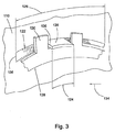
図3は、図2に示した領域3の部分的な斜視的な詳細図である。以下の説明は、図2および図3に相俟って見ることができる。直列ダンパ100は第1のダンパ104及び第2のダンパ106を有している。第1のダンパ104は、第1のカバープレート110と、第2のカバープレート108と、フランジ112とを有している。第2のダンパ106は、第4のカバープレート114と、第3のカバープレート116と、フランジ118と、を有している。第1のダンパ104のフランジ112と第3のカバープレート116とは一貫して延びている。すなわち、第1のダンパ104のフランジ112が第3のプレート116を有しており、この第3のプレート116が第1のダンパ104のフランジ112を有している。以下に詳しく説明するように、第1のダンパ104のフランジ112(第3のプレート116)は第1のカバー110に摩擦係合している。すなわち、第1のダンパ104は、この第1のダンパ104を形成する第1のカバープレート110と、第1のダンパ104のフランジ112との間に摩擦係合部を有している。しかし、第4のカバープレート114と第2のダンパ106のフランジ118とは、主として、第4のカバープレート114または第3のプレート116との摩擦係合なしに回動させられる。これによって、以下にさらに説明するように、ヒステリシス力が第1のダンパ104にしか加えられない。
FIG. 3 is a partial perspective detail view of region 3 shown in FIG. The following description can be seen in conjunction with FIGS. The
幾つかの実施形態では、第3のカバープレート116が軸方向の少なくとも1つの延長部120を有している。この延長部120は、第1のカバープレート110に設けられた該当するスリット122内に配置されている。延長部120の周方向長さ124は、スリット122の周方向の延在長さ126よりも短く寸法設定されている。すなわち、遊びが第1のカバープレート110と延長部120との間に存在している。可撓性のエレメント128が半径方向の少なくとも1つの延長部130を有している。この延長部130は第3のカバープレート116の延長部120内に形状接続的に係合している。技術的に知られている可撓性のあらゆるエレメントをエレメント128に対して使用することができる。一般的には、延長部120,130が第3のプレート116と可撓性のエレメント128とを相対回動不能に結合している。「相対回動不能に結合されている」または「相対回動不能に固定されている」とは、ガイドエレメントとカバープレートとが、一緒に回動させられるように結合されている、すなわち、両構成要素が回動に関して束縛されていることを意味している。両構成要素の相対回動不能な結合は、他方向への運動自由度を必ずしも制限するものではない。たとえば、相対回動不能に結合された2つの構成部材が相互に関してスプライン結合を介した軸方向の可動性を有していることが可能となる。しかし、相対回動不能な結合は、他方向への可動性が必然的に付与されていることを意味するものではないことに留意しなければならない。たとえば、相対回動不能に結合された2つの構成要素が軸方向で互いに固定されていてよい。相対回動不能な結合の前述した説明は、いまや以下の論議に適用される。
In some embodiments, the
可撓性のエレメント128には、トルクコンバータ102の組付けの間にプリロードがかけられ、これによって、可撓性のエレメント128が第1のカバープレート110とタービンハブ132とに作用するようになっている。これは、可撓性のエレメント128が第1のカバープレート110とタービンハブ132とに向かって押圧されることを意味している。すでに留意したように、スリット122の周方向の延在長さ126は延長部120の周方向長さ124よりも大きく寸法設定されている。したがって、第3のカバープレート116が第1のカバープレート110に対して部分的に回動可能となる。たとえば、第3のカバープレート116は、その延長部120の縁部136が可撓性のエレメント128の延長部130の縁部138に当接されるまで方向134に回動可能となる。この部分的な回動は、第1のダンパ104のねじりの間に生ぜしめられる。この第1のダンパ104のねじりの間、可撓性のエレメント128がヒステリシスまたは摩擦力を(可撓性のエレメント128に相対回動不能に結合された)第3のカバープレート116と第1のカバープレート110との間にかつ第3のカバープレート116とタービンハブ132との間に提供する。同時に第2のダンパ106が回動摩擦なしに第4のカバープレート114と、第3のカバープレート116と、フランジ118との間で作業する。
The
図4は、本発明のトルクコンバータ202に設けられた直列ダンパ200の部分的な横断面図である。この直列ダンパ200は第1のダンパ204及び第2のダンパ206を有している。第1のダンパ204は、第1のカバープレート210と、第2のカバープレート208と、フランジ212とを有している。第2のダンパ206は、第3のカバープレート216と、第4のカバープレート214と、フランジ218とを有している。第1のダンパ204のフランジ212と第3のカバープレート216とは一貫して延びている。すなわち、第1のダンパ204のフランジ212が第3のカバープレート216を有しており、この第3のカバープレート216が第1のダンパ204のフランジ212を有している。以下にさらに説明するように、第1のダンパ204のフランジ212(第3のカバープレート216)は回動方向で第1のカバープレート210に摩擦接続的に係合している。すなわち、第1のダンパ204が、この第1のダンパ204を形成する第1のカバープレート210と、第1のダンパ204のフランジ212との間に摩擦接続的な係合部を有している。しかし、第4のカバープレート214と第2のダンパ206のフランジ218とは摩擦接続的な係合なしに自由に回動させられる。たとえば、第2のダンパ206のフランジ218は、回動に関して第4のカバープレート214または第3のカバープレート216に摩擦接続的に係合していない。これによって、ヒステリシス力が第1のダンパ204にしか加えられない。
FIG. 4 is a partial cross-sectional view of the
直列ダンパ200は可撓性のエレメント220とリングエレメントまたは環状のエレメント222とを有している。技術的に知られている可撓性のあらゆるエレメントをエレメント220として使用することができる。リングエレメント222は第3のカバープレート216に相対回動不能に、技術的に知られているあらゆる手段、たとえばそれぞれ第3のカバープレート216およびリングエレメント222に設けられたスプラインおよびスリットによって結合されている。しかし、リングエレメント222は第3のカバープレート216に対して軸方向に運動することができる。幾つかの実施形態では、可撓性のエレメント220が第1のカバープレート210にリベット226によって固定されている。この第1のカバープレート210はタービンハブ224に、技術的に知られているあらゆる手段、たとえばリベットによって固定されている。幾つかの実施形態(図示せず)では、可撓性のエレメント220がタービンハブ224に直接固定されている。可撓性のエレメント220はリングエレメント222を方向228に押圧する。これによって、リングエレメント222が第1のカバープレート210に摩擦接触させられる。これによって、可撓性のエレメント220が摩擦力またはヒステリシス力を第1のダンパ204のフランジ212(第3のカバープレート216)と第1のカバープレート210との間に生ぜしめる。同時に第2のダンパ206が、第4のカバープレート214と、第3のカバープレート216と、第2のダンパ206のフランジ218との間の回動摩擦なしに作業する。
The
以下のことは、図2〜図4に相俟って見ることができる。幾つかの実施形態では、第1のダンパ104;204における摩擦が、内側の第1のカバープレート(それぞれ第1のカバープレート110;210)、すなわち、各トルクコンバータ102;202に用いられる各円環体に向けられた第1のカバープレート110;210に関して存在している。幾つかの実施形態(図示せず)では、第1のダンパ104;204における摩擦が、外側の第2のカバープレート(それぞれ第2のカバープレート108;208)、すなわち、各トルクコンバータ102;202の各カバーに向けられた第2のカバープレート108;208に関して存在している。
The following can be seen in conjunction with FIGS. In some embodiments, the friction in the
ここから明らかとなるように、本発明の目的は、本発明における修正および変更が当業者に明らかであり、この修正が本発明の保護範囲内に位置しているにもかかわらず、有効に達成される。また、前述した説明が単に本発明を例示したものであり、決して限定するものではないことにも留意しなければならない。したがって、本発明の保護範囲を越えることなしに、本発明の別の実施形態が可能となる。 As will become apparent, the objectives of the present invention have been achieved effectively even though modifications and changes in the present invention will be apparent to those skilled in the art and this modification is within the protection scope of the present invention. Is done. It should also be noted that the foregoing description is merely illustrative of the invention and is in no way limiting. Accordingly, other embodiments of the present invention are possible without exceeding the protection scope of the present invention.
80 円筒座標系
81 長手方向軸線
82 半径
83 周
84 対象物
85 対象物
86 対象物
87 面
88 面
89 面
90 対象物
91 軸方向の面
92 半径方向の面
93 周面
100 直列ダンパ
102 トルクコンバータ
104 第1のダンパ
106 第2のダンパ
108 第2のカバープレート
110 第1のカバープレート
112 フランジ
114 第4のカバープレート
116 第3のカバープレート
118 フランジ
120 延長部
122 スリット
124 周方向長さ
126 延在長さ
128 可撓性のエレメント
130 延長部
132 タービンハブ
134 方向
136 縁部
138 縁部
200 直列ダンパ
202 トルクコンバータ
204 第1のダンパ
206 第2のダンパ
208 第2のカバープレート
210 第1のカバープレート
212 フランジ
214 第4のカバープレート
216 第3のカバープレート
218 フランジ
220 可撓性のエレメント
222 リングエレメント
224 タービンハブ
226 リベット
228 方向
80 cylindrical coordinate
Claims (10)
第1および第2のカバープレートと1つのフランジとを備えた第1のダンパを有しており、
第3および第4のカバープレートと1つのフランジとを備えた第2のダンパを有しており、
第1のダンパのフランジと第1のカバープレートとが、回動に関して可撓性のエレメントを介して摩擦接続的に係合しており、
第2のダンパのフランジが、第3および第4のカバープレートに摩擦係合なしに自由に回動させられるようになっていることを特徴とする、直列ダンパ。 In the series damper, the series damper has the following components:
A first damper having first and second cover plates and a flange ;
Having a second damper with third and fourth cover plates and one flange;
The flange of the first damper and the first cover plate are engaged in a frictional connection via a flexible element with respect to rotation,
A series damper characterized in that the flange of the second damper is freely rotatable without frictional engagement with the third and fourth cover plates.
Applications Claiming Priority (3)
| Application Number | Priority Date | Filing Date | Title |
|---|---|---|---|
| US38307P | 2007-10-25 | 2007-10-25 | |
| US61/000,383 | 2007-10-25 | ||
| PCT/DE2008/001665 WO2009052785A1 (en) | 2007-10-25 | 2008-10-09 | Series damper with hysteresis in one damper |
Publications (3)
| Publication Number | Publication Date |
|---|---|
| JP2011501066A JP2011501066A (en) | 2011-01-06 |
| JP2011501066A5 JP2011501066A5 (en) | 2012-12-20 |
| JP5419104B2 true JP5419104B2 (en) | 2014-02-19 |
Family
ID=40242613
Family Applications (1)
| Application Number | Title | Priority Date | Filing Date |
|---|---|---|---|
| JP2010530267A Expired - Fee Related JP5419104B2 (en) | 2007-10-25 | 2008-10-09 | Series damper with hysteresis on one damper |
Country Status (4)
| Country | Link |
|---|---|
| US (1) | US8127905B2 (en) |
| JP (1) | JP5419104B2 (en) |
| DE (2) | DE102008051096A1 (en) |
| WO (1) | WO2009052785A1 (en) |
Families Citing this family (5)
| Publication number | Priority date | Publication date | Assignee | Title |
|---|---|---|---|---|
| DE102008057658A1 (en) * | 2007-11-29 | 2009-06-04 | Luk Lamellen Und Kupplungsbau Beteiligungs Kg | Torque converter with connecting disc for a disc clutch and bow spring |
| DE102011100166B4 (en) * | 2010-05-12 | 2019-11-28 | Schaeffler Technologies AG & Co. KG | Friction package for damper hub |
| JP5684515B2 (en) * | 2010-08-20 | 2015-03-11 | 株式会社エクセディ | Torque converter |
| US8727086B2 (en) * | 2010-12-22 | 2014-05-20 | Schaeffler Technologies Gmbh & Co. Kg | Three-stage hysteresis for series damper |
| US11326678B2 (en) * | 2020-06-17 | 2022-05-10 | Valeo Kapec Co., Ltd. | Friction disc apparatus and related torque converter assemblies for use with vehicles |
Family Cites Families (29)
| Publication number | Priority date | Publication date | Assignee | Title |
|---|---|---|---|---|
| US4347717A (en) * | 1979-12-26 | 1982-09-07 | Borg-Warner Corporation | Two-stage torsional vibration damper |
| CA1157398A (en) * | 1979-12-26 | 1983-11-22 | Paul E. Lamarche | Two-stage torsional vibration damper |
| US4422535A (en) * | 1981-05-20 | 1983-12-27 | Ford Motor Company | Compound damper assembly for an automatic transmission |
| DE3218192A1 (en) * | 1982-05-14 | 1983-11-17 | Fichtel & Sachs Ag, 8720 Schweinfurt | Torsional vibration damper, especially for torque converters |
| DE8509108U1 (en) * | 1985-03-27 | 1992-12-10 | Luk Lamellen Und Kupplungsbau Gmbh, 7580 Buehl, De | |
| JPH0643866B2 (en) * | 1988-10-26 | 1994-06-08 | 株式会社大金製作所 | Friction device for lock-up clutch for torque converter |
| DE3934798A1 (en) * | 1989-10-19 | 1991-04-25 | Fichtel & Sachs Ag | Torsional vibration damper with pre-curved coil springs |
| FR2683011B1 (en) * | 1991-10-25 | 1993-12-10 | Valeo | TORSION DAMPING DEVICE FOR TORQUE TRANSMISSION APPARATUS. |
| US5246399A (en) * | 1991-12-11 | 1993-09-21 | Borg-Warner Automotive Transmission & Engine Components Corporation | Two-stage torsional vibration damper |
| JP2602894Y2 (en) * | 1993-05-26 | 2000-01-31 | 株式会社ユニシアジェックス | Torsional vibration reduction device |
| JPH0960709A (en) * | 1995-08-24 | 1997-03-04 | Nsk Warner Kk | Damper device for torque converter |
| JPH0972399A (en) * | 1995-09-07 | 1997-03-18 | Nsk Warner Kk | Damper device for torque converter |
| JP3644091B2 (en) * | 1995-09-14 | 2005-04-27 | アイシン精機株式会社 | Torque converter direct clutch |
| US6224487B1 (en) * | 1997-04-02 | 2001-05-01 | Borgwarner Inc. | Two stage torsional vibration damper |
| DE19920542A1 (en) * | 1998-05-06 | 1999-11-18 | Luk Getriebe Systeme Gmbh | Power transmission device for road vehicle |
| DE10010953B4 (en) * | 1999-03-10 | 2010-06-02 | Luk Lamellen Und Kupplungsbau Beteiligungs Kg | vibration |
| JP2004308904A (en) * | 2003-04-05 | 2004-11-04 | Zf Sachs Ag | Torsional vibration damper |
| JP2005273709A (en) * | 2004-03-23 | 2005-10-06 | Exedy Corp | Lock-up device for fluid type torque transmission device |
| KR100598845B1 (en) * | 2004-07-06 | 2006-07-11 | 현대자동차주식회사 | A torsional vibration damper |
| JP2006037991A (en) * | 2004-07-22 | 2006-02-09 | Aisin Aw Co Ltd | Lock-up mechanism for torque converter |
| US7658679B2 (en) * | 2005-09-08 | 2010-02-09 | Luk Lamellen Und Kupplungsbau Beteiligungs Kg | Series-parallel multistage torque converter damper |
| DE102005058783A1 (en) * | 2005-12-09 | 2007-06-14 | Zf Friedrichshafen Ag | torsional vibration damper |
| JP4755000B2 (en) * | 2006-03-14 | 2011-08-24 | 株式会社エクセディ | Damper mechanism |
| US20070251788A1 (en) * | 2006-05-01 | 2007-11-01 | Luk Lamellen Und Kupplungsbau Beteiligungs Kg | Drive plate and seal for a torque converter |
| DE102007018273A1 (en) * | 2007-04-18 | 2008-10-23 | Zf Friedrichshafen Ag | Hydrodynamic coupling arrangement |
| DE102008049428A1 (en) * | 2007-10-25 | 2009-04-30 | Luk Lamellen Und Kupplungsbau Beteiligungs Kg | Guide for series damper |
| DE102008049429A1 (en) * | 2007-10-25 | 2009-05-07 | Luk Lamellen Und Kupplungsbau Beteiligungs Kg | Modular spacer for a damper |
| US8135525B2 (en) * | 2007-11-14 | 2012-03-13 | Schaeffler Technologies AG & Co. KG | Torque converter with turbine mass absorber |
| DE102008057658A1 (en) * | 2007-11-29 | 2009-06-04 | Luk Lamellen Und Kupplungsbau Beteiligungs Kg | Torque converter with connecting disc for a disc clutch and bow spring |
-
2008
- 2008-10-09 DE DE102008051096A patent/DE102008051096A1/en not_active Withdrawn
- 2008-10-09 JP JP2010530267A patent/JP5419104B2/en not_active Expired - Fee Related
- 2008-10-09 WO PCT/DE2008/001665 patent/WO2009052785A1/en active Application Filing
- 2008-10-09 DE DE112008002738T patent/DE112008002738A5/en not_active Withdrawn
- 2008-10-24 US US12/288,859 patent/US8127905B2/en not_active Expired - Fee Related
Also Published As
| Publication number | Publication date |
|---|---|
| DE112008002738A5 (en) | 2010-07-15 |
| US8127905B2 (en) | 2012-03-06 |
| US20090107792A1 (en) | 2009-04-30 |
| DE102008051096A1 (en) | 2009-04-30 |
| JP2011501066A (en) | 2011-01-06 |
| WO2009052785A1 (en) | 2009-04-30 |
Similar Documents
| Publication | Publication Date | Title |
|---|---|---|
| JP5419104B2 (en) | Series damper with hysteresis on one damper | |
| US6585091B2 (en) | Torsional vibration damper | |
| JP2003194095A (en) | Torque fluctuation absorber | |
| KR960016600B1 (en) | Torsion damping devices with large angular displacements such as automotive friction clutches | |
| JPS59166724A (en) | Follower plate for driction clutch | |
| JP6066090B2 (en) | Torque converter | |
| US8065872B2 (en) | Axial one way clutch with an axial spacer | |
| DE102017109439A1 (en) | Torsional vibration damper with a torque limiter | |
| KR0174250B1 (en) | Friction clutch driven plates | |
| JP2020037982A5 (en) | ||
| JPH0141848B2 (en) | ||
| CN106838075A (en) | It is particularly used for the frictional disk of motor vehicles | |
| US9810303B2 (en) | Stator cone clutch | |
| US7264102B2 (en) | Clutch driven disc with wave washer | |
| US7980369B2 (en) | Lash prevention spring plate | |
| US20180142739A1 (en) | Clutch structure | |
| US20060096823A1 (en) | Damper disc assembly | |
| US8382598B2 (en) | Modularity spacer for a damper | |
| JP6682701B2 (en) | Torque converter with brazed inertia ring with finger tabs | |
| US20170074379A1 (en) | Turbine shell spring retainer | |
| JP4277507B2 (en) | Torque fluctuation absorber | |
| JP6771816B2 (en) | Rotational force transmission device | |
| KR20200135197A (en) | Transmission Device Equipped With At Least a First Damper and a Dynamic Vibration Absorber | |
| JP5955793B2 (en) | Damper mechanism of torque transmission device | |
| US6299540B1 (en) | Torsional vibration damping device in the drive train of a motor vehicle |
Legal Events
| Date | Code | Title | Description |
|---|---|---|---|
| RD04 | Notification of resignation of power of attorney |
Free format text: JAPANESE INTERMEDIATE CODE: A7424 Effective date: 20101228 |
|
| A521 | Written amendment |
Free format text: JAPANESE INTERMEDIATE CODE: A523 Effective date: 20111011 |
|
| A621 | Written request for application examination |
Free format text: JAPANESE INTERMEDIATE CODE: A621 Effective date: 20111011 |
|
| A131 | Notification of reasons for refusal |
Free format text: JAPANESE INTERMEDIATE CODE: A131 Effective date: 20130215 |
|
| A601 | Written request for extension of time |
Free format text: JAPANESE INTERMEDIATE CODE: A601 Effective date: 20130515 |
|
| A602 | Written permission of extension of time |
Free format text: JAPANESE INTERMEDIATE CODE: A602 Effective date: 20130522 |
|
| A521 | Written amendment |
Free format text: JAPANESE INTERMEDIATE CODE: A523 Effective date: 20130614 |
|
| TRDD | Decision of grant or rejection written | ||
| A711 | Notification of change in applicant |
Free format text: JAPANESE INTERMEDIATE CODE: A711 Effective date: 20131011 |
|
| A01 | Written decision to grant a patent or to grant a registration (utility model) |
Free format text: JAPANESE INTERMEDIATE CODE: A01 Effective date: 20131015 |
|
| A61 | First payment of annual fees (during grant procedure) |
Free format text: JAPANESE INTERMEDIATE CODE: A61 Effective date: 20131113 |
|
| R150 | Certificate of patent or registration of utility model |
Ref document number: 5419104 Country of ref document: JP Free format text: JAPANESE INTERMEDIATE CODE: R150 |
|
| S111 | Request for change of ownership or part of ownership |
Free format text: JAPANESE INTERMEDIATE CODE: R313111 |
|
| R350 | Written notification of registration of transfer |
Free format text: JAPANESE INTERMEDIATE CODE: R350 |
|
| R250 | Receipt of annual fees |
Free format text: JAPANESE INTERMEDIATE CODE: R250 |
|
| R250 | Receipt of annual fees |
Free format text: JAPANESE INTERMEDIATE CODE: R250 |
|
| R250 | Receipt of annual fees |
Free format text: JAPANESE INTERMEDIATE CODE: R250 |
|
| LAPS | Cancellation because of no payment of annual fees |