JP5411552B2 - Lottery device, lottery system and medal game device - Google Patents
Lottery device, lottery system and medal game device Download PDFInfo
- Publication number
- JP5411552B2 JP5411552B2 JP2009083737A JP2009083737A JP5411552B2 JP 5411552 B2 JP5411552 B2 JP 5411552B2 JP 2009083737 A JP2009083737 A JP 2009083737A JP 2009083737 A JP2009083737 A JP 2009083737A JP 5411552 B2 JP5411552 B2 JP 5411552B2
- Authority
- JP
- Japan
- Prior art keywords
- lottery
- medal
- unit
- wheel
- ball
- Prior art date
- Legal status (The legal status is an assumption and is not a legal conclusion. Google has not performed a legal analysis and makes no representation as to the accuracy of the status listed.)
- Expired - Fee Related
Links
Images


Landscapes
- Slot Machines And Peripheral Devices (AREA)
- Time Recorders, Dirve Recorders, Access Control (AREA)
Description
本発明は、抽選装置、抽選システム及びメダルゲーム装置に関する。 The present invention relates to a lottery device, a lottery system, and a medal game device.
従来、プッシャー型と呼ばれるメダルゲーム装置が知られている。プッシャー型のメダルゲーム装置は、筐体内の遊技空間に、前端がメダル獲得口の上方に向かって延設された固定テーブルと、固定テーブルの上面に沿って周期的に往復動されるプッシャーテーブルとを備えている。そして、固定テーブルの上面並びにプッシャーテーブルの上面に、それら上面を概ね覆う程度に多数のメダルが載置される。プッシャーテーブルの前端は、固定テーブル上面との間に隙間がない、或いは、隙間があったとしてもメダル厚さよりも小さい隙間となるような形状を有しており、プッシャーテーブルの前端面で固定テーブル上に載置されたメダルを押すことができるようになっている。 Conventionally, a medal game device called a pusher type is known. The pusher-type medal game device includes a fixed table having a front end extending upward from a medal acquisition port in a game space in the housing, and a pusher table that is periodically reciprocated along the upper surface of the fixed table. It has. A large number of medals are placed on the upper surface of the fixed table and the upper surface of the pusher table to cover the upper surface. The front end of the pusher table has a shape such that there is no gap between the upper surface of the fixed table or a gap smaller than the medal thickness even if there is a gap. The medal placed on the top can be pressed.
遊技者が新たなメダルをメダルゲーム装置に挿入すると、挿入されたメダルと同数のメダルが遊技空間に投入されてプッシャーテーブルの上面に載置される。プッシャーテーブルが固定テーブルに沿ってスライドしながら後進すると、プッシャーテーブルは筐体の挿通孔(出入口)に引っ込む格好になる。プッシャーテーブルの引き込みに伴って、プッシャーテーブルの上面後ろ側に載置されているメダルは挿通孔の端部に当たって相対的に前方に押されることになる。すると、プッシャーテーブルの上面に載置されていた他のメダルは次々に玉突き状に前方側に押され、プッシャーテーブルの前端側に載置されていたメダルが、プッシャーテーブルが後進してできた固定テーブルの上面の空き領域に落下する。 When the player inserts a new medal into the medal game device, the same number of medals are inserted into the game space and placed on the upper surface of the pusher table. When the pusher table moves backward while sliding along the fixed table, the pusher table is retracted into the insertion hole (entrance / exit) of the housing. As the pusher table is retracted, medals placed on the rear side of the upper surface of the pusher table hit the end of the insertion hole and are pushed relatively forward. Then, the other medals placed on the upper surface of the pusher table were pushed forward one after another in a ball shape, and the medals placed on the front end side of the pusher table were fixed by the pusher table moving backward. Drop into an empty area on the top surface of the table.
そして次に、プッシャーテーブルが固定テーブル上をスライドして前進すると、新たに固定テーブル上に落下したメダルがプッシャーテーブルの前端面によって前方に押される。すると今度は固定テーブルの上面に載置されたメダルが次々に連鎖的に前方側に押される格好となる。そして、載置されていたメダルの一部が固定テーブルの前端からメダル獲得口に落下することでメダル払出口からメダルが払い出される。 Next, when the pusher table slides on the fixed table and moves forward, the medal newly dropped on the fixed table is pushed forward by the front end surface of the pusher table. This time, the medals placed on the upper surface of the fixed table are successively pushed forward one after another. The medal is paid out from the medal payout port when a part of the placed medal falls from the front end of the fixed table to the medal acquisition port.
メダルゲーム装置の中には、抽選体を用いた物理的な抽選、いわゆる物理抽選を行う抽選装置を備えたものが知られている(例えば、特許文献1)。こうしたメダルゲーム装置では、固定テーブル上に供給された特別遊技媒体が固定テーブル上に載置されたメダルとともに運ばれてメダル獲得口に落下すると、抽選装置による抽選が実行される構成となっている。メダルとは形状の異なる特別遊技媒体を加えて視覚的に変化を持たせるとともに、この特別遊技媒体のメダル獲得口への落下でもって抽選を実行することで、単にメダルをテーブルから落とすだけでは得られないより「特別な幸運」を手に出来るチャンスに富んだメダルゲームを実現している。 Some medal game devices include a lottery device that performs physical lottery using a lottery body, so-called physical lottery (for example, Patent Document 1). In such a medal game device, when the special game medium supplied on the fixed table is carried together with the medal placed on the fixed table and falls to the medal acquisition port, the lottery device performs the lottery. . A special game medium with a different shape from a medal is added to give a visual change, and a lottery is performed by dropping the special game medium to the medal acquisition port, so that it can be obtained simply by dropping the medal from the table. We have realized a medal game with more chances to get "special luck" than you can.
しかしながら、従来の抽選装置は、単調な物理抽選を行うものが多かった。例えば、特許文献1の抽選装置では、抽選結果(当たり、外れなど)が対応付けられた複数の抽選室を有する環状の抽選部を回転させ、抽選装置に投入された抽選体が抽選部の何れの抽選室に収納されたかに応じて抽選結果が決まるといった構成を採用していた。
However, many conventional lottery devices perform monotonous physical lottery. For example, in the lottery apparatus disclosed in
また、このような物理抽選装置では、抽選確率が一定に保たれるように構成されるのが一般的であるが、ゲーム装置を設置・運営している事業者側としては、ゲームの進行状況や運用等に応じて抽選確率を変動させたい場合がある。 In addition, such physical lottery devices are generally configured so that the lottery probability is kept constant, but as a business operator who installs and operates game devices, the progress of the game In some cases, it is desirable to change the lottery probability according to the operation.
本発明は、上述した課題に鑑みてなされたものであり、第1の目的は、物理抽選を行う抽選装置において、変化に富んだ抽選ゲームを実現することであり、第2の目的は、抽選確率の変動を可能にすることである。 The present invention has been made in view of the above-mentioned problems, and a first object is to realize a lottery game rich in change in a lottery apparatus that performs physical lottery, and a second object is to perform a lottery. It is possible to change the probability.
以上の課題を解決するための第1の発明は、
外周面に球状の抽選体(例えば、図1の抽選球S)が出入りする開口部を設けたポケット部であって、竪穴型のポケット部(例えば、図1の竪穴ポケット部41a)と、竪穴の底部に時計回り方向及び/又は反時計回り方向に横穴を有する屈曲型のポケット部(例えば、図1の屈曲ポケット部41b)とを外周に沿って有する縦型のホイール部(例えば、図1の第2の抽選ホイール部41)と、
前記ホイール部を時計回り又は反時計回りに回転させる回転駆動部(例えば、図2の第2のステッピングモータ43)と、
回転する前記ホイール部の前記開口部が上方を向く所定の投入位置に設けられ、当該投入位置に到来した開口部に抽選体を投入する抽選体投入部(例えば、図1の抽選球投入部45)と、
回転する前記ホイール部の前記開口部が下方を向く位置であって、到達最低位置よりも時計回り方向側の第1の排出位置と反時計回り方向側の第2の排出位置とに設けられ、当該排出位置に到来した開口部と対向するように設けられて、何れの落下口に抽選体が落下するかが抽選結果となる第1及び第2の抽選体落下口部(例えば、図1の第1及び第2の抽選球落下口部46,47)と、
回転する前記ホイール部の外周面に対向するように設けられ、前記第1及び第2の抽選体落下口部以外での抽選体の落下を防止する落下防止部(例えば、図2の窪み42)と、
を備え、前記回転駆動部による回転駆動方向を切替制御して、前記抽選体投入部から投入された抽選体が収容されるポケット部が竪穴型であるか屈曲型であるか、前記ホイール部の回転方向が時計回りか反時計回りかによって、当該抽選体が前記第1及び第2の抽選体落下口部のどちらに落下するかが変化する抽選装置(例えば、図2の第2の抽選装置40)である。
The first invention for solving the above problems is:
A pocket portion provided with an opening through which a spherical lottery body (for example, lottery ball S in FIG. 1) enters and exits on the outer peripheral surface, a pothole-type pocket portion (for example, a
A rotation drive unit (for example, the
The lottery body throwing portion (for example, the lottery
The opening portion of the rotating wheel portion is a position facing downward, and is provided at a first discharge position on the clockwise direction side and a second discharge position on the counterclockwise direction side from the lowest position reached, The first and second lottery body drop opening portions (for example, in FIG. 1) are provided so as to face the opening that has arrived at the discharge position, and the lottery body falls to which dropport is the lottery result. First and second lottery
A fall prevention portion (for example, a
The rotation drive direction by the rotation drive unit is switched, and the pocket portion in which the lottery body inserted from the lottery body insertion unit is accommodated is a pothole type or a bent type, A lottery device (for example, the second lottery device in FIG. 2) that changes whether the lottery body falls into the first or second lottery body outlet depending on whether the rotation direction is clockwise or counterclockwise. 40).
この第1の発明によれば、回転駆動部により、竪穴型のポケット部と屈曲型のポケット部とを外周に沿って有する縦型のホイール部が、時計回り又は反時計回りに回転駆動される。そして、回転駆動部による回転駆動方向が切替制御され、抽選体投入部から投入された抽選体が収容されるポケット部が竪穴型であるか屈曲型であるか、ホイール部の回転方向が時計回りか反時計回りかによって、当該抽選体が第1及び第2の抽選体落下口部のどちらに落下するかが変化し、何れの落下口に抽選体が落下するかが変化する。 According to the first aspect of the invention, the vertical wheel portion having the pothole type pocket portion and the bent pocket portion along the outer periphery is driven to rotate clockwise or counterclockwise by the rotation driving portion. . Then, the rotation drive direction by the rotation drive unit is controlled to be switched, and the pocket portion in which the lottery body inserted from the lottery body insertion portion is accommodated is a pothole type or a bent type, or the rotation direction of the wheel portion is clockwise. Depending on whether it is counterclockwise, the lottery body falls to which of the first and second lottery body drop openings, and to which drop opening the lottery body falls.
従って、抽選体が抽選体投入部に投入されたタイミング、投入された抽選体が収納されたポケット部の種類、ホイール部の回転方向といった複数の要素が絡み合って抽選結果が決まることになるため、従来のような単調な物理抽選ではなく、変化に富んだ物理抽選が実行されるようになる。また、回転駆動部による回転駆動方向を遊技中に切替制御することで、ゲームの進行状況や運用等に応じて抽選確率を変動させることが可能となる。 Therefore, since the lottery results are determined by a plurality of factors such as the timing at which the lottery body is inserted into the lottery body insertion portion, the type of the pocket portion in which the lottery body is stored, and the rotation direction of the wheel portion are intertwined. Instead of the conventional monotonous physical lottery, a variety of physical lotteries are executed. In addition, by performing switching control of the rotation driving direction by the rotation driving unit during the game, it becomes possible to vary the lottery probability according to the progress of the game and the operation.
また、第2の発明として、
少なくとも2つの第1の発明の抽選装置(例えば、図2の第1及び第2の抽選装置30,40)を上下方向に並べて具備するとともに、
前記2つの抽選装置のうちの上方の抽選装置が備える前記第1及び第2の抽選体落下口部のうちの一方の抽選体落下口部(例えば、図1の第1の抽選球落下口部36)と、下方の抽選装置が備える前記抽選体投入部(例えば、図1の抽選球投入部45)とを連通させ、当該一方の抽選体落下口部に落下した抽選体を連通先の抽選体投入部に案内する通路部(例えば、図1の連結通路50)と、
を具備し、前記2つの抽選装置双方又は一方の前記回転駆動部による回転駆動方向を切替制御して、前記上方の抽選装置が備える前記第1及び第2の抽選体落下口部のうちの他方の抽選体落下口部(例えば、図1の第2の抽選球落下口部37)と、前記下方の抽選装置が備える前記第1及び第2の抽選体落下口部(例えば、図1の第1及び第2の抽選球落下口部46,47)とのうちの何れの落下口部に抽選体が落下するかが変化する抽選システム(例えば、図2の抽選システム20)を構成してもよい。
As a second invention,
At least two lottery apparatuses according to the first invention (for example, the first and
Of the two lottery devices, one of the first and second lottery body drop port portions provided in the upper lottery device (for example, the first lottery ball drop port portion of FIG. 1). 36) and the lottery body insertion unit (for example, the lottery
And the other of the first and second lottery body drop openings provided in the upper lottery device by switching and controlling the rotational drive direction of both of the two lottery devices or one of the rotational drive units. The lottery body drop opening part (for example, the second lottery ball
この第2の発明によれば、少なくとも2つの抽選装置を上下方向に並べて抽選システムが構成される。抽選システムは、2つの抽選装置のうちの上方の抽選装置が備える第1及び第2の抽選体落下口部のうちの一方の抽選体落下口部と、下方の抽選装置が備える抽選体投入部とを連通する通路部を備えて構成される。そして、回転駆動部により2つの抽選装置双方又は一方の回転駆動方向が切替制御される。この結果、上方の抽選装置が備える他方の抽選体落下口部と、下方の抽選装置が備える抽選体落下口部とのうちの何れの落下口部に抽選体が落下するかが変化し、抽選結果が変化する。 According to the second aspect, at least two lottery devices are arranged in the vertical direction to constitute a lottery system. The lottery system includes one of the first and second lottery body outlets provided in the upper lottery device of the two lottery devices, and the lottery body input unit provided in the lower lottery device. And a passage portion that communicates with each other. Then, both the two lottery devices or one of the rotation drive directions is switched and controlled by the rotation drive unit. As a result, it changes whether the lottery body falls to which of the other lottery body drop opening part provided in the upper lottery apparatus and the lottery body drop opening part provided in the lower lottery apparatus, The result changes.
第1の発明の作用効果を奏する複数の抽選装置によって抽選システムが構成されるため、物理抽選のランダム性が高まる。すなわち、抽選システムには複数のホイール部が含まれることから、各ホイール部の2種類のポケット部の何れに抽選体が収納されたか、各ホイール部の回転方向が時計回り/反時計回りの何れであるかといった複数の要素が抽選結果に大きな影響を及ぼすことになる。そのため、従来にない変化に富んだ抽選ゲームを遊技者に提供することが可能となる。 Since the lottery system is configured by a plurality of lottery apparatuses that exhibit the effects of the first invention, the randomness of the physical lottery increases. That is, since the lottery system includes a plurality of wheel portions, which of the two types of pocket portions of each wheel portion stores the lottery body, and whether the rotation direction of each wheel portion is clockwise or counterclockwise. A number of factors such as whether or not will greatly affect the lottery result. Therefore, it is possible to provide a player with a lottery game rich in changes that has not been made in the past.
また、第3の発明として、第2の発明の抽選システムであって、
前記2つの抽選装置は、ホイール部の大きさが異なり、前記竪穴型のポケット部と前記屈曲型のポケット部との構成数比率が異なる(例えば、図1の第1及び第2の抽選ホイール部31,41)、
抽選システムを構成してもよい。
Moreover, as 3rd invention, it is the lottery system of 2nd invention,
The two lottery devices have different wheel sizes, and the number ratios of the hole-type pocket portion and the bent pocket portion are different (for example, the first and second lottery wheel portions in FIG. 1). 31, 41),
You may comprise a lottery system.
この第3の発明によれば、2つの抽選装置のホイール部の大きさや、各ホイール部の竪穴型のポケット部と屈曲型のポケット部との構成数比率が異なることで、抽選体の動きに変化を持たせることができ、物理抽選のランダム性が高まる。 According to the third aspect of the invention, the size of the wheel portions of the two lottery devices and the ratio of the number of the hole-type pocket portions and the bent pocket portions of the wheel portions are different. Changes can be made, increasing the randomness of physical lottery.
この場合、さらに第4の発明として、第2又は第3の発明の抽選システムであって、
前記2つの抽選装置の前記ホイール部の回転速度が異なる(例えば、図1の第1及び第2の抽選ホイール部31,41)、
抽選システムを構成することも可能である。
In this case, as a fourth invention, the lottery system of the second or third invention,
The rotation speeds of the wheel portions of the two lottery devices are different (for example, the first and second
It is also possible to configure a lottery system.
この第4の発明によれば、2つの抽選装置のホイール部の回転速度が異なることで、抽選体の動きに一層の変化を持たせることができる。 According to the fourth aspect of the present invention, the movement of the lottery body can be further changed by the rotational speeds of the wheel portions of the two lottery apparatuses being different.
また、第5の発明として、
メダル投入口(例えば、図1〜図3のメダル投入部10)からメダル(例えば、図2のメダルM)が投入されることでゲームフィールド(例えば、図1及び図2の固定テーブル6)にメダルを放出し、前記ゲームフィールドからメダル獲得口(例えば、図1のメダル獲得口4)にメダルが落下することでメダルを払い出すプッシャー型のメダルゲーム装置(例えば、図1のメダルゲーム装置1000)であって、
第1の発明の抽選装置(例えば、図2の第2の抽選装置40)と、
前記抽選装置が備える第1及び第2の抽選体落下口部のうちの一方の前記抽選体落下口部に落下した抽選体を前記ゲームフィールド上に案内して排出する第1の排出案内部(例えば、図1の普通当たり抽選球案内レール75)と、
前記抽選装置が備える他方の前記抽選体落下口部に落下した抽選体を前記メダル獲得口に案内して落下させる第2の排出案内部(例えば、図1の大当たり抽選球案内レール70)と、
前記メダル獲得口に落下したメダル及び抽選体の中から抽選体を選別する選別部と、
前記選別部により選別された抽選体を回収する回収部と、
を具備し、前記回収部により抽選体が回収された場合に、所定数のメダルをボーナスメダルとして払い出す或いは前記ゲームフィールドに放出するメダルゲーム装置を構成してもよい。
As a fifth invention,
A medal (for example, medal M in FIG. 2) is inserted from a medal insertion slot (for example,
A lottery apparatus of the first invention (for example, the
A first discharge guide section (1) that guides and discharges the lottery body that has fallen into one of the first and second lottery body drop opening sections included in the lottery apparatus onto the game field. For example, the normal lottery
A second discharge guide part (for example, the big hit lottery
A selection unit for selecting a lottery from among medals and lotteries dropped in the medal acquisition port;
A collection unit for collecting the lottery objects sorted by the sorting unit;
And a medal game device that pays out a predetermined number of medals as bonus medals or releases them to the game field when the lottery is collected by the collecting unit.
この第5の発明によれば、抽選装置が備える第1及び第2の抽選体落下口部のうちの一方の抽選体落下口部に抽選体が落下した場合には、その抽選体は、ゲームフィールドに案内される。ゲームフィールド上の抽選体は、やがてメダルの流れに乗って運ばれることで、メダル獲得口に落下することとなる。他方の抽選体落下口部に抽選体が落下した場合には、その抽選体は、直接メダル獲得口に案内される。また、メダル獲得口に抽選体が落下した場合には、所定数のメダルがボーナスメダルとして払い出されるか、或いは、ゲームフィールドに放出されることとなる。 According to the fifth aspect, when the lottery body falls into one of the first and second lottery body drop opening portions of the lottery apparatus, the lottery body is a game. Guided to the field. The lottery bodies on the game field will eventually fall into the medal acquisition port by being carried on the medal flow. When the lottery body falls to the other lottery body drop opening, the lottery body is directly guided to the medal acquisition port. Further, when the lottery body falls to the medal acquisition port, a predetermined number of medals are paid out as bonus medals or released to the game field.
第1の発明の作用効果を奏する抽選装置を備えたメダルゲーム装置が実現されるため、遊技者は、メダルプッシャーゲームと併せて、興趣溢れる抽選ゲームを楽しむことができる。また、抽選体がメダル獲得口に落下した場合は、ボーナスメダルが遊技者に提供されるが、抽選装置の抽選結果によっては抽選体が直接メダル獲得口に落下して、ボーナスメダルが即座に支給されることとなるため、“特別な幸運”が得られることとなる。 Since the medal game device provided with the lottery device having the effects of the first invention is realized, the player can enjoy a lottery game full of interest together with the medal pusher game. If the lottery falls to the medal acquisition slot, a bonus medal is provided to the player, but depending on the lottery result of the lottery device, the lottery falls directly to the medal acquisition slot and the bonus medal is immediately provided. As a result, "special luck" will be obtained.
この場合、さらに第6の発明として、第5の発明のメダルゲーム装置であって、
前記抽選装置が備える前記回転駆動部(例えば、図2の第2のステッピングモータ43;図4の第2の抽選ホイール駆動部304)による回転駆動方向を切替制御して前記抽選装置による抽選確率を変更する抽選確率変更部(例えば、図4の第2の抽選ホイール制御部204)を更に具備するメダルゲーム装置を構成することも可能である。
In this case, as a sixth invention, the medal game device of the fifth invention,
The lottery probability by the lottery device is controlled by switching the rotational drive direction by the rotation drive unit (for example, the
また、第7の発明として、
メダル投入口(例えば、図1〜図3のメダル投入部10)からメダル(例えば、図2のメダルM)が投入されることでゲームフィールド(例えば、図1及び図2の固定テーブル6)にメダルを放出し、前記ゲームフィールドからメダル獲得口(例えば、図1のメダル獲得口4)にメダルが落下することでメダルを払い出すプッシャー型のメダルゲーム装置(例えば、図1のメダルゲーム装置1000)であって、
第2〜第4の何れかの発明の抽選システム(例えば、図2の抽選システム20)と、
前記抽選システムが備える何れかの前記抽選体落下口部に落下した抽選体を前記ゲームフィールド上に案内して排出する第1の排出案内部(例えば、図1の普通当たり抽選球案内レール75)と、
前記抽選システムが備える何れかの前記抽選体落下口部に落下した抽選体を前記メダル獲得口に案内して落下させる第2の排出案内部(例えば、図1の大当たり抽選球案内レール70)と、
前記メダル獲得口に落下したメダル及び抽選体の中から抽選体を選別する選別部と、
前記選別部により選別された抽選体を回収する回収部と、
を具備し、前記回収部により抽選体が回収された場合に、所定数のメダルをボーナスメダルとして払い出す或いは前記ゲームフィールドに放出するメダルゲーム装置を構成してもよい。
As a seventh invention,
A medal (for example, medal M in FIG. 2) is inserted from a medal insertion slot (for example,
A lottery system according to any one of the second to fourth inventions (for example, the
A first discharge guide section for guiding and discharging a lottery body that has fallen into any of the lottery body drop openings provided in the lottery system (for example, a normal lottery
A second discharge guide section (for example, the big hit lottery
A selection unit for selecting a lottery from among medals and lotteries dropped in the medal acquisition port;
A collection unit for collecting the lottery objects sorted by the sorting unit;
And a medal game device that pays out a predetermined number of medals as bonus medals or releases them to the game field when the lottery is collected by the collecting unit.
この場合、さらに第8の発明として、第7の発明のメダルゲーム装置であって、
前記抽選システムが備える抽選装置全部又は一部の前記回転駆動部(例えば、図2の第1及び第2のステッピングモータ33,43;図4の第1及び第2の抽選ホイール駆動部302,304)による回転駆動方向を切替制御して前記抽選システムによる抽選確率を変更する抽選確率変更部(例えば、図4の第1及び第2の抽選ホイール制御部202,204)を更に具備するメダルゲーム装置を構成してもよい。
In this case, as an eighth invention, the medal game device of the seventh invention,
All or part of the lottery devices included in the lottery system (for example, the first and
また、第9の発明として、第6又は第8の発明のメダルゲーム装置であって、
前記メダル投入口に投入されたメダル数(例えば、図4のメダル投入枚数512)と払い出したメダル数(例えば、図4のメダル払出枚数514)とからペイアウト率(例えば、図4のペイアウト率516)を算出するペイアウト率算出部(例えば、図4のペイアウト率算出部214)を更に具備し、
前記抽選確率変更部は、前記ペイアウト率に基づいて、前記回転駆動方向の切替制御を行う(例えば、図5のホイール回転駆動方向切替制御データ508、図6のステップA6)、
メダルゲーム装置を構成してもよい。
According to a ninth invention, there is provided a medal game device according to the sixth or eighth invention,
A payout rate (for example,
The lottery probability changing unit performs the rotation drive direction switching control based on the payout rate (for example, wheel rotation drive direction switching
A medal game device may be configured.
この第9の発明によれば、ペイアウト率算出部により、メダル投入口に投入されたメダル数と払い出したメダル数とからペイアウト率が算出される。そして、抽選確率変更部が、ペイアウト率算出部により算出されたペイアウト率に基づいて、回転駆動方向の切替制御を行う。 According to the ninth aspect, the payout rate calculation unit calculates the payout rate from the number of medals inserted into the medal slot and the number of medals paid out. Then, the lottery probability changing unit performs rotation drive direction switching control based on the payout rate calculated by the payout rate calculating unit.
ペイアウト率が基準値より高い場合は抽選確率が低くなるように回転駆動方向を切替制御し、ペイアウト率が基準値より低い場合は抽選確率が高くなるように回転駆動方向を切替制御することで、現状のペイアウト率に見合った適切な運用を図ることができる。 When the payout rate is higher than the reference value, the rotational drive direction is switched so that the lottery probability is low, and when the payout rate is lower than the reference value, the rotational drive direction is switched so that the lottery probability is high, Appropriate operation corresponding to the current payout rate can be achieved.
以下、図面を参照して、本発明を適用したメダルゲーム装置について説明する。尚、以下のメダルゲーム装置の説明における方向は、遊技を行う遊技者の視点に立った方向を指すものとし、手前側を前、奥側を後、ゲーム装置に向かった上下左右それぞれの方向を上下左右それぞれの方向とする。 A medal game device to which the present invention is applied will be described below with reference to the drawings. The directions in the description of the medal game device below refer to the direction from the viewpoint of the player who performs the game, and the front side is the front side, the back side is the back side, the top, bottom, left, and right directions are directed to the game device. The directions are up, down, left and right.
1.第1実施形態
1−1.概略構成
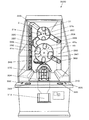
図1は、第1実施形態におけるメダルゲーム装置1000の構成を示す正面外観図であり、図2は、メダルゲーム装置1000の主要部の縦断面図である。メダルゲーム装置1000は、透明カバーガラス2及び支持板3で囲まれた遊技空間GSを画成し、この遊技空間GS内に前端がメダル獲得口4の上方に向かって延設された固定テーブル6と、この固定テーブル6の上面に沿って周期的に往復動されるプッシャーテーブル8とを備えて構成されている。メダルゲーム装置1000は、いわゆる「プッシャー型」のメダルゲーム装置に分類される。
1. 1. First embodiment 1-1. Schematic Configuration FIG. 1 is a front external view showing a configuration of a
メダルゲーム装置1000は、遊技者が新たなメダルMを投入するためのメダル投入器10を左右に1つずつ備えている。また、メダルゲーム装置1000は、立設盤SBの下部であって、メダル投入器10のメダル放出口10eから放出されたメダルが衝突する位置近傍にルーレット装置15を備えるとともに、立設盤SBの内部にいわゆる物理抽選を行う抽選システム20を備える。ルーレット装置15は、ルーレットゲームを行い、その成否に応じて抽選システム20による抽選を発動させる権利を付与するか否かを決定するための装置である。
The
遊技開始前には、メダルゲーム装置1000の管理人らによって、固定テーブル6並びにプッシャーテーブル8の上面に多数のメダルMが予め載置される。そして、遊技の進行に伴い、遊技者によりメダル投入器10に新たなメダルMが投入され、プッシャーテーブル8の上面に次々とメダルMが載置されることになる。
Before the game is started, a number of medals M are placed in advance on the upper surfaces of the fixed table 6 and the pusher table 8 by the managers of the
プッシャーテーブル8は、固定テーブル6上にスライド移動可能に載置されている。台座内には、図2に示すように、ステッピングモータ9aを具備した往復動機構9が設けられており、ステッピングモータ9aの動作により、プッシャーテーブル8が立設盤SBの下部に開口する挿通孔7から出入りするように前後方向に周期的に往復運動する。
The pusher table 8 is slidably mounted on the fixed table 6. As shown in FIG. 2, a reciprocating mechanism 9 having a stepping
プッシャーテーブル8が、固定テーブル6上をスライドするようにして後進(退行)すると、その上面に載置されているメダルMも載置されたまま一緒に後進する。プッシャーテーブル8が後進に伴って挿通孔7に引き込まれると、後進した分だけプッシャーテーブル8の延出長が短くなり、プッシャーテーブル8の上面後方に載置されていたメダルMが挿通孔7の周縁に当って相対的に前方に押される格好になる。すると、プッシャーテーブル8に載置されていた他のメダルMも玉突き状に連鎖的に前方へ押され、ついには前端側に載っているメダルMが固定テーブル6上に落下する。 When the pusher table 8 moves backward (retreats) so as to slide on the fixed table 6, the medal M placed on the upper surface of the pusher table 8 moves backward together. When the pusher table 8 is pulled back into the insertion hole 7, the extension length of the pusher table 8 is shortened by the amount of backward movement, and the medal M placed on the rear surface of the pusher table 8 is inserted into the insertion hole 7. It hits the edge and is pushed relatively forward. Then, the other medals M placed on the pusher table 8 are also pushed forward in a chain-like manner, and finally the medals M placed on the front end side fall on the fixed table 6.
その後、プッシャーテーブル8の前進(押出動作)に伴ってその前方端面が押出部として機能し、固定テーブル6の上面に落下して固定テーブル6に載置されたメダルMは前方に押される(プッシュされる。)。すると今度は、固定テーブル6に載置されているメダルMが玉突き状に前方へ押され、固定テーブル6の手前側に載置されているメダルMから順にメダル獲得口4に落下する。
Thereafter, as the pusher table 8 advances (extrusion operation), its front end surface functions as an extruding portion, and the medal M dropped on the upper surface of the fixed table 6 and placed on the fixed table 6 is pushed forward (pushing). .) Then, this time, the medal M placed on the fixed table 6 is pushed forward in the shape of a ball, and falls to the
メダル獲得口4の下部は、落下したメダルMの通過を検出する通過センサ11を備えた通路に連通している。通過センサ11は、物体の通過を検出する手段であって、例えば投光素子と受光素子とが対向配置された遮光によって物体の通過を検出するセンサや、超音波の反射時間から距離を計測する距離センサなどによって実現できる。通過する物体に接触して揺動する揺動スイッチなどでも良い。メダル獲得口4に落下したメダルMは、この通路を通ってメダル払出口13に案内され、遊技者に払い出される。
The lower part of the
抽選システム20は、球状の抽選体である抽選球Sを用いて物理抽選を行う。抽選システム20による最終的な抽選結果が“大当たり”である場合は、大当たり抽選球案内レール70によって抽選球Sがメダル獲得口4に案内される。メダル獲得口4の下部には、メダル獲得口4に落下したメダルM及び抽選球Sの中から抽選球Sを選別する公知の選別機構(不図示)と、選別機構により選別された抽選球Sを貯留部に回収する公知の回収機構(不図示)とが備えられている。そして、メダル獲得口4に抽選球Sが落下したことが検知されると、特典として、所定枚数(例えば30枚)のメダルMがボーナスメダルとしてメダル払出口13から払い出される。
The
尚、“大当たり”でなくとも、メダルの流れに乗って固定テーブル6上の抽選球Sがメダル獲得口4に落下する場合があるのは勿論である。“大当たり”の場合には、直接、抽選球Sがメダル獲得口4に落下することとなり、ボーナスメダルが即座に支給されることとなるため、遊技者は“特別な幸運”を得ることができる。
Of course, the lottery ball S on the fixed table 6 may fall into the
他方、抽選結果が“普通当たり”の場合には、普通当たり抽選球案内レール75によって抽選球Sが固定テーブル6上に案内され、抽選結果が“外れ”の場合には、抽選球回収穴59に抽選球Sが回収される。
On the other hand, when the lottery result is “normal hit”, the lottery ball S is guided onto the fixed table 6 by the normal lottery
ルーレット装置15は、図3に示すように、左右方向に一列に配列されたルーレットランプ(ルーレットLED)RLを備えて構成され、点灯させるランプを所定の移動表示速度で高速に切り替えることで標的表示を左右に往復するように移動表示させる、ルーレットの出目の移動制御(以下、「ランプ移動制御」という。)を行う。そして、後述する停止タイミングにおいてランプ移動制御を停止する。もし、当該停止タイミングにおいて点灯しているランプが当たりランプRsであればルーレットゲームは「成功」であるとして、抽選システム20による抽選権利を付与して、抽選システム20による抽選を開始する。一方、外れランプRfであればルーレットゲームを「失敗」として、抽選権利が与えられず、抽選システム20による抽選が行われない。
As shown in FIG. 3, the
立設盤SBの左下部及び右下部であって、左右に備えられたメダル投入器10のメダル放出口10eから放出されたメダルが衝突する部位には、所定のマークMKが描画されている。マークMKは、メダルMの当接位置を遊技者に示すとともに、マークMKにメダルMが当接した時がルーレット装置15によるランプ移動制御の停止タイミングであることを示している。
Predetermined marks MK are drawn on the lower left part and the lower right part of the standing board SB, at the parts where the medals released from the
制御ユニット80には、CPU(Central Processing Unit)82やICメモリ84などの電子・電気部品が実装されており、ICメモリ84に予め記憶されていたプログラムに従ってCPU82が各種演算処理を実行してメダルゲーム装置1000の各部の制御を実行する。
Electronic and electrical components such as a CPU (Central Processing Unit) 82 and an
スピーカ90は、遊技中におけるBGMを出力したり、ルーレット装置15によるルーレットゲームの成否に応じた演出音声を出力したり、抽選システム20による抽選結果に応じた演出音声を出力したりする音出力装置である。
The
1−2.メダル投入器の構成
図2及び図3を参照しつつメダル投入器10の構成について説明する。図3は、メダルゲーム装置1000に備えられた右側のメダル投入器10及びその周辺を拡大した部分拡大図である。メダル投入器10は、メダルMを立てた状態で、メダルMが自重により手前方から奥方に向けて回転落下するメダル投入レール10cを備えて構成されている。メダル投入レール10cは、メダルMを立てた状態に維持しつつ回転落下方向をガイドする壁面部とメダルMの落下面を形成する床面部とによって樋状の溝を形成している。メダル投入レール10cは、奥側が手前側よりも低くなるように傾斜しており、溝の幅がメダルMの幅よりも僅かに広くなっているため、メダルMはメダル投入レール10cを手前方から奥方に向けて回転しながら落下する。
1-2. Configuration of Medal Inserter The configuration of the
メダル投入器10の一端(手前側)は、支持板3に設けられたメダル投入口10aでなり、このメダル投入口10aは、連結通路10bを介してメダル投入レール10cに連通している。メダル投入口10aは、その幅がメダルMの幅よりも僅かに広くなっており、遊技者がメダルMを立てた状態で1枚ずつ投入可能に構成されている。
One end (front side) of the
メダル投入口10aに投入されたメダルMは、連結通路10bを通過してメダル投入レール10cに導かれるが、連結通路10bは、図2に示すようにメダル投入口10aに投入されたメダルMの進行方向を鉛直下向きに変化させた後にメダル投入レール10cに導く、Z字状に屈曲したクランク形状をなしている。このため、メダルMは、投入時の勢いが減殺されて一旦落下させられた後に、メダル投入口10aの下方に設けられたメダル投入レール10cに案内される。このように、メダル投入器10は、勢いをつけてメダルMが投入された場合にも、メダル投入レール10cを回転落下し始める速度をほぼ同一として、常に同じような速度でメダルMを回転落下させる機構となっている。
The medal M inserted into the
メダル投入器の他端(奥側)の開口はメダル放出口10eとなっており、樋状のメダル投入レール10cを転動してメダル放出口10eから放出されたメダルMが、ルーレットランプRLの下方に描画されたマークMKに当接するように、メダル投入器10が位置決めされている。
The opening at the other end (back side) of the medal insertion device is a
また、メダル投入レール10cのメダル放出口10eよりも僅かに手前側には、メダルMの通過を検出する通過センサ10dが配置されている。通過センサ10dは、例えば投光素子と受光素子とが対向配置された遮光によって物体の通過を検出するセンサや、超音波の反射時間から距離を計測する距離センサなどによって実現できる。通過する物体に接触して揺動する揺動スイッチなどでもよい。
Further, a
本実施形態では、通過センサ10dによりメダルMの通過が検知されて後、予め規定された経過時間(以下、「規定経過時間」という。)が経過したタイミングを停止タイミングとして、ルーレット装置15のランプ移動制御を停止させる制御を行う。この規定経過時間は、通過センサ10dによりメダルMの通過が検出されてからメダルMがマークMKに当接するまでの時間である。
In the present embodiment, after the passage of the medal M is detected by the
前述したように、メダル投入レール10cは、メダルMの投入時の勢い如何に関わらず、常に同じ速度でメダルMを回転落下させるため、メダルMが通過センサ10dにより検出されてからマークMKに当接するまでの時間は一定である(厳密には多少の誤差はあるが、人間が視覚的に認知できる時間としては一定と言える)。そのため、メダルゲーム装置1000の製造段階において、実際にメダルMをメダル投入器10に投入して試験を行い、投入されたメダルMが通過センサ10dにより検出されて後、当該メダルMがメダル放出口10eから放出されてマークMKに当接するまでの時間を測定することで、規定経過時間が設定される。
As described above, the
特徴的であることの1つは、実際にメダルMがマークMKに当接したタイミングを検出してランプ移動制御を停止させるのではなく、通過センサ10dによりメダルMの通過が検出されてから規定経過時間が経過したタイミングでランプ移動制御を停止させる点である。この制御により、あたかもメダルMがマークに当接した瞬間にランプ移動制御が停止したかのように遊技者を錯覚させることが可能となる。
One characteristic is not to stop the lamp movement control by detecting the timing at which the medal M actually contacts the mark MK, but to be defined after the passage of the medal M is detected by the
1−3.抽選システムの構成
次に、本実施形態における抽選システム20の構成について詳細に説明する。抽選システム20は、遊技空間GSの奥に立設された立設盤SBに設けられた2台の抽選装置である第1の抽選装置30と第2の抽選装置40とが上下方向に並べて配置されるとともに、第1の抽選装置30及び第2の抽選装置40を連結する連結通路50を備えて構成される。
1-3. Next, the configuration of the
第1の抽選装置30は、立設盤SBの上部に設けられた正面視円形の窪み32に嵌め込むように形成された第1の抽選ホイール部31と、第1の抽選ホイール部31を回転駆動する第1のステッピングモータ33とを備えて構成される。第1のステッピングモータ33は、制御ユニット80からの駆動制御信号に従って、第1の抽選ホイール部31を指定される回転方向(時計回り/反時計回り)及び回転速度で回転させる。
The
第1の抽選ホイール部31の外周側面は円滑面で形成されているが、抽選球Sが出入りする開口部が4箇所等間隔に設けられている。そのうちの3箇所の開口部は、竪穴型のポケット部である竪穴ポケット部31aの開口部である。竪穴ポケット部31aの深さは、抽選球1個がちょうど収まる深さとなるように設計されている。また、残る1箇所の開口部は、屈曲型のポケット部である屈曲ポケット部31bの開口部である。屈曲ポケット部31bは、竪穴の底部に図1に向かって時計回り方向に横穴を有した長靴を模した形状を有しており、この屈曲ポケット部31bを形成する竪穴及び横穴の長さは、抽選球1個がちょうど収まるような長さとなるように設計されている。
Although the outer peripheral side surface of the first
図1において、立設盤SBには、第1の抽選ホイール部31の時計文字盤で言う10時の位置に抽選球投入部35が設けられている。抽選球投入部35は、立設盤SBの左部に鉛直方向に形成された抽選球収納部55の上端と連通して一体的に形成されており、抽選球収納部55の上端部から下方に向けて傾斜する傾斜通路でなる。
In FIG. 1, the standing board SB is provided with a lottery
抽選球収納部55は、抽選球Sの直径よりやや大きい内径を有する筒状の通路でなり、抽選球収納部55の下方には抽選球Sの落下を阻止するとともに、下から新たな抽選球Sを押し込んで押し上げる公知の押し上げ機構(不図示)が具備されている。抽選球収納部55の通路内に抽選球Sが積み上げられた状態で、押し上げ機構により当該通路の下方から新たな抽選球Sが1つ押し上げられると、積み上げられている抽選球S全体が更に上方に押し上げられる。そして、抽選球収納部55の上端に達した抽選球Sが、傾斜通路をなす抽選球投入部35に落下する。
The lottery
抽選球投入部35に落下してきた抽選球Sは、第1の抽選ホイール部31の外周側面に当接してその位置に留まるが、第1の抽選ホイール部31の回転によって、竪穴ポケット部31a或いは屈曲ポケット部31bの開口部が、抽選球投入部35の対向位置に到来すると、その開口部を通じて、当該ポケット部に転落する。抽選球投入部35は下方に向けて開口しており、これに対向するように、第1の抽選ホイール部31の外周側面に形成された何れかの開口部が到来することで、当該開口部が上方を向く位置となって、抽選球Sが当該ポケット部に転落する。
The lottery ball S that has fallen into the lottery
図1において、立設盤SBには、第1の抽選ホイール部31の時計文字盤で言うところの8時の位置に第1の抽選球落下口部36が設けられている。第1の抽選球落下口部36は、第1の抽選ホイール部31と第2の抽選ホイール部41とを連結する連結通路50の上端に連通している。第1の抽選ホイール部31の竪穴ポケット部31a或いは屈曲ポケット部31bの開口部が第1の抽選球落下口部36の対向位置に到来すると、その開口部を通じて、抽選球Sが第1の抽選球落下口部36に転落する。そして、抽選球Sは、連結通路50を通って第2の抽選ホイール部41へと導かれる。
In FIG. 1, the standing board SB is provided with a first lottery
図1において、立設盤SBには、第1の抽選ホイール部31の時計文字盤で言うところの4時の位置に第2の抽選球落下口部37が設けられている。第2の抽選球落下口部37は、抽選結果が“外れ”として抽選球Sを回収するための抽選球回収穴59に抽選球Sを導く案内通路58の上端と連結している。抽選球回収穴59に回収された抽選球Sは、立設盤SBの内部に形成された抽選球搬送機構60を通じて抽選球の貯留部(不図示)に搬送される。
In FIG. 1, the standing board SB is provided with a second lottery ball drop opening 37 at the 4 o'clock position on the clock face of the
第1の抽選ホイール部31は、上述したように立設盤SBの上部に設けられた正面視円形の窪み32に嵌め込むように形成されている。そのため、第1の抽選ホイール部31の竪穴ポケット部31a或いは屈曲ポケット部31bの開口部は、第1の抽選球落下口部36又は第2の抽選球落下口部37の対向位置に到来する場合を除き、窪み32の外周壁面と対向することになる。そのため、窪み32の外周壁面が抽選球Sの落下防止部として機能し、第1及び第2の抽選球落下口部以外での抽選球Sの落下が防止される。
As described above, the first
第2の抽選装置40は、第1の抽選装置30と略同一の構成を有する抽選装置である。そのため、詳細な説明を省略して主要な構成を説明する。第2の抽選装置40は、図2に示すように、立設盤SBの下部に設けられた正面視円形の窪み42に嵌め込むように形成された第2の抽選ホイール部41と、第2の抽選ホイール部41を回転駆動する第2のステッピングモータ43とを備え、制御ユニット80からの駆動制御信号に従って第2の抽選ホイール部41の回転方向(時計回り/反時計回り)及び回転速度が可変に制御される。
The
第2の抽選ホイール部41は、第1の抽選ホイール部31とは異なり、2つの竪穴ポケット部41aと2つの屈曲ポケット部41bとを有している。第2の抽選ホイール部41は、第1の抽選ホイール部31と同様、正面視円形の形状を有するが、2つのホイール部は大きさが異なる。具体的には、第2の抽選ホイール部41の方が、第1の抽選ホイール部31よりも一回り大きなサイズとなるように設計されている。
Unlike the first
また、第1の抽選ホイール部31と第2の抽選ホイール部41とでは、ポケット部の構成数比率が異なる。すなわち、竪穴ポケット部と屈曲型ポケット部との構成数比率は、第1の抽選ホイール部31では「3:1」であるのに対し、第2の抽選ホイール部41では「1:1」である。
Further, the first
図1において、立設盤SBには、第2の抽選ホイール部41の時計文字盤で言うところの10時の位置に抽選球投入部45が設けられている。抽選球投入部45は、連結通路50の下端と連通して一体的に形成されている。また、時計文字盤で言うところの8時の位置に第1の抽選球落下口部46が設けられている。第1の抽選球落下口部46は、大当たり抽選球案内レール70の一端に連通しており、大当たり抽選球案内レール70の他端は、メダル獲得口4の上方に位置している。すなわち、第1の抽選球落下口部46に転落した抽選球Sは、大当たり抽選球案内レール70の上を転動してメダル獲得口4に直接落下することとなる。
In FIG. 1, the standing board SB is provided with a lottery
図1において、立設盤SBには、第2の抽選ホイール部41の時計文字盤で言うところの4時の位置に第2の抽選球落下口部47が設けられている。第2の抽選球落下口部47は、普通当たり抽選球案内レール75の一端と連通しており、普通当たり抽選球案内レール75の他端は、固定テーブル6の上方に位置している。すなわち、第2の抽選球落下口部47に転落した抽選球Sは、普通当たり抽選球案内レール75の上を転動して固定テーブル6上に落下することとなる。
In FIG. 1, the standing board SB is provided with a second lottery ball drop opening 47 at the 4 o'clock position on the clock face of the
以上の構成をなす第1の抽選ホイール部31及び第2の抽選ホイール部41は、第1のステッピングモータ33及び第2のステッピングモータ43によって、それぞれ図1に向かって時計回り又は反時計回りの方向に回転するように駆動制御される。より具体的には、メダル投入器10から投入されたメダルの総数であるメダル投入枚数と、メダル払出口13から払い出したメダルの総数であるメダル払出枚数とを用いてペイアウト率が算出され、このペイアウト率に基づいて、第1及び第2のステッピングモータ33,43による回転駆動方向が切替制御される。
The first
また、第1の抽選ホイール部31及び第2の抽選ホイール部41は、第1のステッピングモータ33及び第2のステッピングモータ43によって、それぞれ異なる回転速度で回転するように駆動制御される。具体的には、第2の抽選ホイール部41の回転速度が、第1の抽選ホイール部31の回転速度よりも大きな値となるように設定されており、第2の抽選ホイール部41は第1の抽選ホイール部31よりも高速で回転するように駆動制御される。
Further, the first
抽選システム20により行われる抽選の抽選確率は、第1及び第2の抽選ホイール部31,41の回転方向が時計回り/反時計回りの何れであるかに応じて変化する。以下、第1及び第2の抽選ホイール部31,41の回転方向がそれぞれ時計回り/反時計回りである場合における抽選システム20による抽選の流れ及び抽選確率について、場合を分けて詳細に説明する。
The lottery probability of the lottery performed by the
(1)第1及び第2の抽選ホイール部の回転方向が共に時計回りである場合
先ず、不図示の押し上げ機構により抽選球収納部55の下方から新たな抽選球Sが挿入され、積み上げられた抽選球Sの列が上方に押し上げられると、最上位に位置する抽選球Sが抽選球投入部35の傾斜通路を沿って落下する。第1の抽選ホイール部31は常時回転制御されているため、最初に到来したポケット部に抽選球Sが転落・投入されることとなるが、竪穴ポケット部31aに投入された場合には、時計回りに回転して竪穴ポケット部31aの開口部が第2の抽選球落下口部37の対向位置に到来したときに、抽選球Sは当該竪穴ポケット部31aから第2の抽選球落下口部37に転落し、回収される。この場合の抽選結果が“外れ”である。
(1) When the rotation directions of the first and second lottery wheel portions are both clockwise First, a new lottery ball S is inserted and stacked from below the lottery
一方、抽選球Sが屈曲ポケット部31bに投入された場合には、時計回りに回転して、当該屈曲ポケット部31bの開口部が第2の抽選球落下口部37の対向位置に到来しても、抽選球Sは第2の抽選球落下口部37には転落しない。屈曲ポケット部31bには時計回り方向に横穴が形成されている。第1の抽選ホイール部31が時計回り方向に回転している間に、屈曲ポケット部31bの開口部の向きが図1に向かって真上〜右上〜右〜右下〜下〜左下の順に変位するが、開口部の向きが真上〜右となる間に、屈曲ポケット部31bの横穴は、下向きとなる。従い、この間に抽選球Sは屈曲ポケット部31bの横穴に移動することとなる。そして、開口部の向きが右〜右下〜下となる間は、横穴が逆さになることがないため、抽選球Sは依然として横穴の中に留まるのである。第2の抽選球落下口部37は、時計文字盤で言うところの4時の位置にあるため、屈曲ポケット部31bの開口部が第2の抽選球落下口部37の対向位置に位置したとしても、抽選球Sは横穴に留まり、転落することはない。
On the other hand, when the lottery ball S is thrown into the
第1の抽選ホイール部31が更に時計回り方向に回転して、屈曲ポケット部31bの開口部の向きが下〜左下となると、横穴が逆さになり、横穴に留まっていた抽選球Sが屈曲ポケット部31の竪穴に落下し、開口部に位置するようになる。そして、当該開口部が第1の抽選球落下口部36の対向位置に位置すると、抽選球Sは、第1の抽選球落下口部36に落下し、連結通路50を通って第2の抽選ホイール部41の抽選球投入部45に案内される。
When the
抽選球投入部45に案内された抽選球Sは、第1の抽選ホイール部31と同様、第2の抽選ホイール部41の何れかのポケット部に投入されることとなる。このとき、抽選球Sが竪穴ポケット部41aに投入されると、当該竪穴ポケット部41aの開口部が第2の抽選球落下口部47の対向位置に到来したときに、当該竪穴ポケット部41aから第2の抽選球落下口部47に転落して、普通当たり抽選球案内レール75によって固定テーブル6上へと案内される。この場合の抽選結果が“普通当たり”である。
As with the first
一方、抽選球Sが屈曲ポケット41bに投入されると、第1の抽選ホイール部31と同様の原理により、当該屈曲ポケット部41bの開口部が第2の抽選球落下口部47の対向位置を超えて、第1の抽選球落下口部46の対向位置に到来したときに第1の抽選球落下口部46に落下し、大当たり抽選球案内レール70によって直接メダル獲得口4へと案内される。この場合の抽選結果が“大当たり”である。
On the other hand, when the lottery ball S is thrown into the
第1の抽選ホイール部31は、3つの竪穴ポケット部31aと1つの屈曲ポケット部41bとを有しているため、抽選球Sが第1の抽選ホイール部31から第2の抽選ホイール部41へと案内される確率は「1/4」である。第2の抽選ホイール部41へ抽選球Sが案内された場合、必ず“普通当たり”か“大当たり”となる。従って当選確率は「1/4」と言える。
Since the first
また、第2の抽選ホイール部41は、2つの竪穴ポケット部41aと2つの屈曲ポケット部41bとを有しているため、抽選球Sが第2の抽選ホイール部41からメダル獲得口4へと案内される確率は「1/2」である。従って、“大当たり”となる確率は「1/8」、“普通当たり”となる確率も「1/8」と言える。
Further, since the second
(2)第1の抽選ホイール部の回転方向が時計回りであり、第2の抽選ホイール部の回転方向が反時計回りである場合
第1の抽選ホイール部31の回転に伴う抽選球Sの動き(遷移)は、(1)と同様である。第1の抽選ホイール部31の開口部から抽選球投入部45に案内された抽選球Sは、第2の抽選ホイール部41の何れかのポケット部に投入されることとなる。このとき、第2の抽選ホイール部41は反時計回りに回転しているため、抽選球Sが竪穴ポケット部41aに投入されると、当該竪穴ポケット部41aの開口部が第1の抽選球落下口部46の対向位置に到来したときに、抽選球Sは当該竪穴ポケット部41aから第1の抽選球落下口部46に転落して、大当たり抽選球案内レール70によって直接メダル獲得口4へと案内される。
(2) When the rotation direction of the first lottery wheel unit is clockwise and the rotation direction of the second lottery wheel unit is counterclockwise, the movement of the lottery ball S accompanying the rotation of the first lottery wheel unit 31 (Transition) is the same as (1). The lottery ball S guided from the opening of the first
一方、抽選球Sが屈曲ポケット部41bに投入されると、第2の抽選ホイール部41が反時計回り方向に回転している間に、屈曲ポケット部41bの開口部の向きが図1に向かって左上〜左〜左下の順に変位する。第2の抽選ホイール部41は時計回り方向に横穴を有しているため、開口部の向きが左上〜左となる間は、屈曲ポケット部41bの横穴は右上〜上向きとなり、竪穴の底部が開口部よりも低くなるため、開口部から投入された抽選球Sは、屈曲ポケット部41bの竪穴の底部に留まる。第2の抽選ホイール部41が更に反時計回り方向に回転すると開口部が左〜左下に変化し、竪穴の底部に留まっていた抽選球Sは、開口部に滑落する。そして、屈曲ポケット部41bの開口部が第1の抽選球落下口部46の対向位置に到来したときに、抽選球Sは開口部から第1の抽選球落下口部46に落下し、大当たり抽選球案内レール70によって直接メダル獲得口4へと案内される。
On the other hand, when the lottery ball S is thrown into the
従って、抽選球Sが第1の抽選ホイール部31から第2の抽選ホイール部41に案内された場合は、抽選球Sが投入されるポケット部の種類に関わらず、抽選結果は必ず“大当たり”となる。すなわち、抽選球Sが第2の抽選ホイール部41からメダル獲得口4へと案内される確率は「1」である。(1)で説明したように、抽選球Sが第1の抽選ホイール部31から第2の抽選ホイール部41へと案内される確率は「1/4」であるため、抽選結果が“大当たり”となる確率は「1/4」、“普通当たり”となる確率は「0」と言える。
Therefore, when the lottery ball S is guided from the first
(3)第1の抽選ホイール部の回転方向が反時計回りであり、第2の抽選ホイール部の回転方向が時計回りである場合
第1の抽選ホイール部31の回転に伴う抽選球Sの動き(遷移)は、(2)の第2の抽選ホイール部41と同様となる。従って、第1の抽選ホイール部31に案内された抽選球Sは、必ず第2の抽選ホイール部41へと案内されることになる。すなわち、抽選球Sが第1の抽選ホイール部31から第2の抽選ホイール部41へと案内される確率は「1」である。
(3) When the rotation direction of the first lottery wheel unit is counterclockwise and the rotation direction of the second lottery wheel unit is clockwise, the movement of the lottery ball S accompanying the rotation of the first lottery wheel unit 31 (Transition) is the same as the second
また、第2の抽選ホイール部41の回転に伴う抽選球Sの動き(遷移)は、(1)と同様であるため、抽選球Sが第2の抽選ホイール部41からメダル獲得口4へと案内される確率は「1/2」である。よって、抽選結果が“大当たり”となる確率は「1/2」、“普通当たり”となる確率も「1/2」と言える。
Further, since the movement (transition) of the lottery ball S accompanying the rotation of the second
(4)第1及び第2の抽選ホイール部の回転方向が共に反時計回りの場合
第1の抽選ホイール部31の回転に伴う抽選球Sの動きは、(3)と同様であり、第2の抽選ホイール部41の回転に伴う抽選球Sの動きは、(2)と同様である。従って、第1の抽選ホイール部31に案内された抽選球Sは、必ず第2の抽選ホイール部41へと案内され、第2の抽選ホイール部41に案内された抽選球Sは、必ずメダル獲得口4へと案内される。そのため、抽選結果が“大当たり”となる確率は「1」、“普通当たり”となる確率は「0」と言える。
(4) When the rotation directions of the first and second lottery wheel portions are both counterclockwise, the movement of the lottery ball S accompanying the rotation of the first
1−4.機能構成
図4は、メダルゲーム装置1000の機能構成を示すブロック図である。メダルゲーム装置1000は、メダル投入検出部102と、メダル落下検出部104と、抽選球落下検出部106と、処理部200と、第1の抽選ホイール駆動部302と、第2の抽選ホイール駆動部304と、ルーレット装置306と、押し上げ機構308と、音出力部400と、記憶部500とを備えて構成される。
1-4. Functional Configuration FIG. 4 is a block diagram showing a functional configuration of the
メダル投入検出部102は、遊技者がメダル投入口10aに投入したメダルMの通過を検出する検出部であり、検出信号を処理部200に出力する。メダル投入検出部102は、図1〜図3の通過センサ10dに相当する。
The medal
メダル落下検出部104は、固定テーブル6からメダル獲得口4に落下したメダルを検出する検出部であり、検出信号を処理部200に出力する。メダル落下検出部104は、図1の通過センサ11に相当する。
The medal
抽選球落下検出部106は、固定テーブル6からメダル獲得口4に落下した抽選球Sを検出する検出部であり、検出信号を処理部200に出力する。
The lottery ball
処理部200は、メダルゲーム装置1000の各部の動作を制御する制御部である。図1では、制御ユニット80がこれに相当し、制御ユニット80に搭載されたCPU、DSP、ASIC等の演算装置により、記憶部500に記憶されているプログラムやデータが読み出されて実行されることで、各種機能が実現される。
The
処理部200は、第1の抽選ホイール制御部202と、第2の抽選ホイール制御部204と、ルーレット制御部206と、抽選球投入制御部208と、メダル払出制御部210と、演出制御部212と、ペイアウト率算出部214と、音生成部216と、タイマー218とを備えている。
The
第1の抽選ホイール制御部202は、第1の抽選ホイール駆動部302に駆動制御信号を出力して、記憶部500に記憶されているホイール回転駆動方向切替制御データ508に従って決定した回転駆動方向及びホイール回転速度設定データ510に定められた回転速度で第1の抽選ホイール部31を回転駆動させるように制御する。第2の抽選ホイール制御部204も同様に、第2の抽選ホイール駆動部304に駆動制御信号を出力して、第2の抽選ホイール部41を回転駆動させるように制御する。
The first lottery
第1の抽選ホイール駆動部302は、第1の抽選ホイール制御部202からの駆動制御信号に従って第1の抽選ホイール部31を駆動させる駆動装置であり、図2の第1のステッピングモータ33がこれに相当する。第2の抽選ホイール駆動部304も同様に、第2の抽選ホイール制御部204からの駆動制御信号に従って第2の抽選ホイール部41を駆動させる駆動装置であり、図2の第2のステッピングモータ43がこれに相当する。
The first lottery
ルーレット制御部206は、ルーレット装置306に制御信号を出力して、ルーレット装置306にルーレットの出目の移動制御(ランプ移動制御)を行わせる制御部である。
The
ルーレット装置306は、ルーレット制御部206からの制御信号に従ったランプ移動制御を行う装置であり、図1のルーレット装置15がこれに相当する。
The roulette device 306 is a device that performs lamp movement control in accordance with a control signal from the
抽選球投入制御部208は、押し上げ機構308に制御信号を出力して、新たな抽選球S1つを抽選球収納部55内に下方から挿入させる制御を行い、抽選球収納部55の最上位に位置する抽選球Sを抽選球投入部35に落下させる。
The lottery ball throwing-in
押し上げ機構308は、抽選球収納部55内に下方から新たな抽選球Sを押し込み、抽選球収納部55内に積み上がっている抽選球Sを上方に押し上げるとともに、抽選球収納部55内の抽選球Sの荷重を支え、落下を阻止する弁機構を有して構成される。
The push-up
メダル払出制御部210は、抽選球落下検出部106により抽選球Sがメダル獲得口4に落下したことが検出された場合に、メダル獲得口4内に設けられた不図示のメダル排出口から所定枚数のメダルMをボーナスメダルとして落下させて、メダルを払い出すように制御する制御部である。
When the lottery ball drop detecting
演出制御部212は、ルーレット装置306によるランプ移動制御の結果に応じた演出制御を行う制御部である。停止タイミングにおいて点灯しているランプが当たりランプRsであるか否かに応じた音声出力演出を行ったり、抽選球落下検出部106による検出結果に応じてボーナスメダルの排出に関する音声出力演出を行う。
The
ペイアウト率算出部214は、メダル投入検出部102により投入が検出されたメダルの総数であるメダル投入枚数512と、メダル落下検出部104により落下が検出されたメダルの総数であるメダル払出枚数514とを用いて、ペイアウト率516を算出する算出部である。
The payout
音生成部216は、遊技中におけるBGMや、ルーレットゲームの成否に応じた演出音声、抽選システム20による抽選結果に応じた演出音声等の音信号を生成する生成部であり、生成した音信号を音出力部400に出力する。
The
音出力部400は、音生成部216から出力される音信号に基づいた音出力を行う音出力装置であり、図1のスピーカ90がこれに相当する。
また、タイマー218は、所与のスタートタイミングからの経過時間を計測する計時部である。
The
The
記憶部500は、処理部200にメダルゲーム装置1000を統括的に制御させるためのシステムプログラム等の各種プログラムや各種データを記憶した記憶装置である。記憶部500の機能は、例えばICメモリやハードディスク、メモリカード、光ディスク、CD―ROM、DVD−ROM/RAM等の情報記憶媒体により実現される。図1では、制御ユニット80に搭載されるメモリ84がこれに相当する。
The
本実施形態では、記憶部500は、予め記憶されているプログラム及びデータとして、制御プログラム502と、規定経過時間504と、目標ペイアウト率506と、ホイール回転駆動方向切替制御データ508と、ホイール回転速度設定データ510とを格納している。また、遊技の進行に応じて生成・更新されるデータとして、メダル投入枚数512と、メダル払出枚数514と、ペイアウト率516とが格納される。
In the present embodiment, the
制御プログラム502は、メダルゲーム装置1000における遊技の進行を制御し、処理部200を上述した各種機能部として機能させるためのプログラムである。
The
規定経過時間504は、メダル投入検出部102によりメダルMの通過が検出されて後、ルーレット装置306のランプ移動制御を停止させるまでの時間として予め規定された時間である。目標ペイアウト率506は、ペイアウト率516の目標値であり、予め設定される。
The specified elapsed
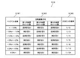
図5は、ホイール回転駆動方向切替制御データ508のデータ構成の一例を示す図である。ホイール回転駆動方向切替制御データ508には、現在のペイアウト率516から目標ペイアウト率506を減算したペイアウト率差5081と、第1の抽選ホイール部31及び第2の抽選ホイール部41それぞれの回転駆動方向5083と、大当たりの確率5085とが対応付けて記憶されている。
FIG. 5 is a diagram illustrating an example of a data configuration of the wheel rotation drive direction switching
具体的には、ペイアウト率差5081が高くなるほど、大当たりの確率5085が低くなるように、回転駆動方向5083が定められている。例えば、ペイアウト率差5081が「−10%以下」である場合は、回転駆動方向5083は第1の抽選ホイール部31が反時計回り、第2の抽選ホイール部41が時計回りであり、この場合の大当たりの確率5085は「1/2」である。
Specifically, the
ホイール回転速度設定データ510は、第1の抽選ホイール部31及び第2の抽選ホイール部41それぞれの回転速度が定められたデータである。第2の抽選ホイール部41の回転速度には、第1の抽選ホイール部31の回転速度よりも大きな値が設定されている。
The wheel rotation
メダル投入枚数512は、メダル投入器10に投入されたメダルの総数であり、メダル投入検出部102によりメダルの投入が検出される毎に更新される。メダル払出枚数514は、メダル払出口13から払い出されたメダルの総数であり、メダル落下検出部104によりメダルの落下が検出される毎に更新される。ペイアウト率516は、メダル投入枚数512に対するメダル払出枚数514の割合であり、ペイアウト率算出部214により算出・更新される。
The
1−5.処理の流れ
図6及び図7は、記憶部500に記憶されている制御プログラム502が処理部200により読み出されて実行されることで、メダルゲーム装置1000において実行される制御処理の流れを示すフローチャートである。
1-5. Flow of Processing FIGS. 6 and 7 show the flow of control processing executed in the
先ず、処理部200は、メダル落下検出部104から検出信号を入力したか否かを判定し(ステップA1)、入力したと判定した場合は(ステップA1;Yes)、記憶部500に記憶されているメダル払出枚数514を更新する(ステップA3)。そして、ペイアウト率算出部214は、記憶部500に記憶されているメダル投入枚数512とメダル払出枚数514とを用いてペイアウト率516を算出して更新する(ステップA5)。
First, the
次いで、第1の抽選ホイール制御部202及び第2の抽選ホイール制御部204は、記憶部500に記憶されている現在のペイアウト率516から目標ペイアウト率506を減算してペイアウト率差5081を算出し、ホイール回転駆動方向切替制御データ508に基づいて、第1の抽選ホイール駆動部302及び第2の抽選ホイール駆動部304による回転駆動方向5083を切替制御する(ステップA6)。
Next, the first lottery
次いで、処理部200は、抽選球落下検出部106から検出信号を入力したか否かを判定する(ステップA7)。そして、入力したと判定した場合は(ステップA7;Yes)、メダル払出制御部210が、メダル獲得口4内に設けられたメダル排出口(不図示)から所定枚数のメダルMをボーナスメダルとして落下させて、メダル払出口13から払い出すように制御する(ステップA9)。
Next, the
次いで、処理部200は、メダル投入検出部102から検出信号を入力したか否かを判定し(ステップA11)、入力しなかったと判定した場合は(ステップA11;No)、ステップA1に戻る。また、入力したと判定した場合は(ステップA11;Yes)、処理部200は、フラグがOFFに設定されているか否かを判定する(ステップA13)。
Next, the
フラグは、ルーレットランプ移動制御が停止されて後、再始動されるまでの一連の処理が行われている間ONに設定されるフラグであり、フラグがONに設定されている期間は対応不可期間となって、ステップA15〜A47の処理が行われない。従って、例えば遊技者によってメダル投入器10にメダルが連続投入されたような場合は、1枚目に投入されたメダルについて上述した処理が行われ、2枚目以降に投入されたメダルについては上述した処理が行われないことになる。
The flag is a flag that is set to ON while a series of processes from when the roulette lamp movement control is stopped to when the roulette lamp movement control is restarted. Thus, the processing of steps A15 to A47 is not performed. Therefore, for example, when a player continuously inserts medals into the
ステップA13においてフラグがOFFに設定されていると判定した場合は(ステップA13;Yes)、処理部200は、フラグをONに設定し(ステップA15)、タイマー218をスタートさせる(ステップA17)。そして、処理部200は、記憶部500に記憶されているメダル投入枚数512を更新し(ステップA19)、ペイアウト率算出部214が、記憶部500に記憶されているメダル投入枚数512とメダル払出枚数514とを用いて、ペイアウト率516を算出して更新する(ステップA21)。
If it is determined in step A13 that the flag is set to OFF (step A13; Yes), the
次いで、処理部200は、記憶部500に記憶されているペイアウト率516が目標ペイアウト率506を超えているか否かを判定し(ステップA23)、超えていると判定した場合は(ステップA23;Yes)、変動時間を決定する(ステップA25)。変動時間は、例えば最大「0.1秒」までの時間を乱数を使って決定する。
Next, the
そして、処理部200は、記憶部500に記憶されている規定経過時間504に変動時間を加算した時間を経過時間として設定する(ステップA27)。また、ステップA23においてペイアウト率516が目標ペイアウト率506を超えていないと判定した場合は(ステップA23;No)、処理部200は、記憶部500に記憶されている規定経過時間504を経過時間として設定する(ステップA29)。
Then, the
次いで、処理部200は、ステップA27又はA29で設定した経過時間が経過したか否かを判定し(ステップA31)、まだ経過していないと判定した場合は(ステップA31;No)、そのまま待機する。また、経過時間が経過したと判定した場合は(ステップA31;Yes)、処理部200は、タイマー218をリセットさせる(ステップA33)。そして、ルーレット制御部206が、ルーレット装置306にランプ移動制御を停止させるように制御する(ステップA35)。
Next, the
その後、処理部200は、点灯しているルーレットランプRLの種類を判定し(ステップA37)、当たりランプRsであると判定した場合は(ステップA37;当たりランプ)、演出制御部212が成功演出制御を行う(ステップA39)。具体的には、ルーレットゲームの成功を演出する演出音声や演出音楽を音生成部216に生成させ、音出力部400から出力させる。
After that, the
そして、抽選球投入制御部206は、第1の抽選ホイール部31に連通する抽選球投入部35へと抽選球Sを投入させるように、抽選球投入部306を制御する(ステップA41)。また、ルーレット制御部206が、ルーレット装置306にランプ移動制御を開始させる(ステップA43)。そして、処理部200は、フラグをOFFに設定した後(ステップA45)、ステップA1に戻る。
Then, the lottery ball throwing
また、ステップA41において点灯しているルーレットランプRLが外れランプRfであると判定した場合は(ステップA37;外れランプ)、演出制御部212が、失敗演出制御を行う(ステップA47)。具体的には、ルーレットゲームの失敗を演出する演出音声や演出音楽を音生成部216に生成させ、音出力部400から出力させる。そして、処理部200は、ステップA1に戻る。
When it is determined in step A41 that the lit roulette lamp RL is the detachment lamp Rf (step A37; detachment lamp), the
一方、ステップA13においてフラグがONに設定されていると判定した場合は(ステップA13;No)、処理部200は、現在は対応不可期間であると判断し、記憶部500に記憶されているメダル投入枚数512を更新する(ステップA49)。また、ペイアウト率算出部214が、記憶部500に記憶されているメダル投入枚数512とメダル払出枚数514とを用いてペイアウト率516を算出して更新する(ステップA51)。そして、処理部200は、ステップA1に戻る。
On the other hand, if it is determined in step A13 that the flag is set to ON (step A13; No), the
1−6.作用効果
メダルゲーム装置1000は、プッシャー型のメダルゲーム装置であり、抽選球Sを用いた物理抽選を行うための抽選システム20を備えて構成される。抽選システム20は、第1の抽選装置30と第2の抽選装置40との2つの抽選装置を上下方向に並べて具備している。第1の抽選装置30は、円盤状のホイール部である第1の抽選ホイール部31と第1のステッピングモータ33とを備え、第1の抽選ホイール部31は、第1のステッピングモータ33によって時計回り又は反時計回りに回転するように駆動制御される。第2の抽選装置40も、第1の抽選装置30と同様、円盤状のホイール部である第2の抽選ホイール部41と第2のステッピングモータ43とを備え、第2の抽選ホイール部41は、第2のステッピングモータ43により時計回り又は反時計回りに回転するように駆動制御される。
1-6. Operational Effect The
第1及び第2の抽選ホイール部31,41には、それぞれ竪穴型のポケット部である竪穴ポケット部31a,41aと、竪穴の底部に時計回り方向に横穴を有する屈曲型のポケット部である屈曲ポケット部31b,41bとを外周に沿って有している。そして、抽選球Sが抽選体収納部55から抽選球投入部35に投入された場合に、抽選球Sが落下した第1の抽選ホイール部31のポケット部の種類、及び、第1の抽選ホイール部31の回転方向に応じて、抽選球Sの行き先が変化する。抽選球Sが時計盤で言うところの8時の位置に設けられた第1の抽選球落下口部36に落下すると、抽選球Sは連絡通路50を通じて第2の抽選ホイール部41へと案内される。しかし、抽選球Sが時計盤で言うところの4時の位置に設けられた第2の抽選球落下口部37に落下すると、抽選結果は“外れ”となり、回収機構によって回収される。
Each of the first and second
抽選球Sが第2の抽選ホイール部41に案内されると、抽選球Sは第2の抽選ホイール部41が備えるポケット部に落下するが、抽選球Sが落下した第2の抽選ホイール部41のポケット部の種類、及び、第2の抽選ホイール部41の回転方向に応じて、抽選球Sの行き先が変化する。抽選球Sが時計盤で言うところの8時の位置に設けられた第1の抽選球落下口部46に落下すると、抽選結果は“大当たり”となり、抽選球Sはメダル獲得口4に案内されて落下する。他方、抽選球Sが時計盤で言うところの4時の位置に設けられた第2の抽選球落下口部47に落下すると、抽選結果は“普通当たり”となり、抽選球Sは固定テーブル6へと案内されて排出される。
When the lottery ball S is guided to the second
このような構成により、抽選球Sがどのタイミングで抽選球投入部35に投入されたか、抽選球Sが落下したのが竪穴ポケット部と屈曲ポケット部との何れの種類のポケット部であるか、抽選ホイール部の回転方向が時計回り、反時計回りの何れであるかといった複数の要素が絡み合って抽選結果が決まるため、抽選体を用いた物理抽選に面白みを持たせ、従来にない興趣のある抽選ゲームを遊技者に提供することが可能となる。
With such a configuration, at which timing the lottery ball S is thrown into the lottery
また、第1の抽選ホイール部31と第2の抽選ホイール部41とは大きさが異なり、竪穴ポケット部と屈曲ポケット部との構成数比率も異なる。その上、第1の抽選ホイール部31と第2の抽選ホイール部41とは異なる回転速度で回転するように駆動制御される。かかる構成により、抽選球Sの動きに予想もできないような変化を持たせ、物理抽選のランダム性を高めることができる。
In addition, the first
さらに、メダルゲーム装置1000では、ペイアウト率に基づいて、第1及び第2のステッピングモータ33,43による回転駆動方向が切替制御される。具体的には、現在ペイアウト率から目標ペイアウト率を減算したペイアウト率差が低いほど大当たりの確率が高く、ペイアウト率差が高いほど大当たりの確率が低くなるように回転駆動方向が切替制御される。これにより、抽選確率を適切に変動させることが可能となり、効率的な運用を図ることができるようになる。
Further, in the
2.第2実施形態
2−1.構成
図8は、第2実施形態におけるメダルゲーム装置2000の構成を示す正面外観図である。第1実施形態におけるメダルゲーム装置1000と同一の構成要素については同一の符号を付して説明を省略する。メダルゲーム装置2000では、第1種抽選球S1と、第2種抽選球S2との2種類の抽選球を用いて、抽選システム20による物理抽選を実行する。第1種抽選球S1は、例えば黒色が施された球状の抽選体である。他方、第2種抽選球S2は、白色が施された球状の抽選体であり、抽選確率を一時的に引き上げる特典付きの抽選体である。
2. Second Embodiment 2-1. Configuration FIG. 8 is a front external view showing the configuration of the
立設盤SBの左部に鉛直方向に設けられた抽選球収納部55であって、抽選球収納部55を構成する筒状の通路の上部には、抽選球収納部55の最上位に位置し、次に投入されることとなる抽選球の種類を検出するための抽選球種類検出センサ55aが配置されている。抽選球種類検出センサ55aは、例えば投光素子と受光素子とを備えて構成され、抽選球に対して投光した光の抽選球からの反射光の強度を測定することによって、抽選球収納部55の最上位に位置する抽選球の種類を判定する。
A lottery
2−2.処理の流れ
図9は、メダルゲーム装置2000の処理部200が行う第2の制御処理のうち、図6の制御処理に相当する部分を示すフローチャートである。尚、図6の制御処理と同一のステップについては同一の符号を付して説明を省略し、制御処理とは異なる部分を中心に説明する。
2-2. Process Flow FIG. 9 is a flowchart showing a portion corresponding to the control process of FIG. 6 in the second control process performed by the
処理部200は、ステップA9においてメダル払出制御を行った後、抽選球種類検出センサ55aから、抽選球収納部55の最上位に位置する抽選球の種類を取得する(ステップB11)。そして、処理部200は、取得した抽選球の種類が第2種抽選球であるか否かを判定し(ステップB13)、第2種抽選球であると判定した場合は(ステップB13;Yes)、大当たりの確率が最大となるような回転駆動方向で第1及び第2の抽選ホイール部31,41を回転させるように、第1及び第2の抽選ホイール駆動部302,304を駆動制御する(ステップB15)。そして、処理部200は、ステップA11へと処理を移行する。
After performing the medal payout control in Step A9, the
2−3.作用効果
メダルゲーム装置2000が備える抽選システム20は、第1種抽選球S1と第2種抽選球S2との2種類の抽選球を用いて物理抽選を行う。第2種抽選球S2は、抽選確率を一時的に引き上げる特典が付与された抽選体である。抽選球収納部55に設けられた抽選球種類検出センサ55aにより、抽選システム20に次回投入予定の抽選球の種類が第2種抽選球S2であることが検出されると、抽選結果が“大当たり”となる確率が最大となるように、第1及び第2のステッピングモータ33,43による回転駆動方向が切替制御される。このように抽選球の種類に応じて抽選確率を変動させるようにしたことで、抽選体を用いた物理抽選に更なる面白みを持たせることができるようになり、抽選ゲームの興趣性が一層高まる。
2-3. Effect The
3.第3実施形態
図10は、第3実施形態におけるゲーム装置3000の構成を示す正面外観図である。ゲーム装置3000は、カプセル入りの玩具、いわゆるカプセルトイを取得するための子供用のゲーム装置である。ゲーム装置3000では、上述した第1及び第2実施形態の抽選球Sとして、球状のカプセルCを用いて物理抽選を実行する。カプセルCの中には、任意の景品を封入することが可能であり、例えば、アニメキャラクタの人形や消しゴム、各種の乗り物の小型模型などが考えられる。
3. Third Embodiment FIG. 10 is a front external view showing a configuration of a
ゲーム装置3000は、テーブル300の上面に、硬貨を投入するためのコイン投入口310と、抽選システムによる抽選を指示するための抽選開始ボタン320とを配置して有している。また、ゲーム装置3000は、第1及び第2実施形態のメダルゲーム装置1000,2000と同様の抽選システム20を備えている。そして、例えば、第1の抽選ホイール部31は、第1の時間間隔(例えば“5分間隔”)で時計回り/反時計回りを切り替えて回転駆動され、第2の抽選ホイール部41は、第2の時間間隔(例えば“10分間隔”)で時計回り/反時計回りを切り替えて回転駆動される。
The
カプセルCが第1の抽選ホイール部31から第2の抽選ホイール部41へと案内され、第1のカプセル落下口部346に落下すると、抽選結果は“当たり”となり、カプセルCは当たりカプセル案内レール370の上を転動してカプセル獲得口304に落下し、カプセル払出口313から払い出される。一方、カプセルCが第2のカプセル落下口部337或いは347に落下すると、それぞれカプセル回収穴359,369に回収されて、搬送機構360により搬送される。
When the capsule C is guided from the first
このように、第3実施形態では、メダルゲーム装置ではなく、玩具が封入されたカプセルを用いて物理抽選を行い、抽選結果が当たりとなった場合にそのカプセルを払い出すゲーム装置を実現できる。 Thus, in the third embodiment, it is possible to realize a game device that performs physical lottery using a capsule in which a toy is enclosed instead of a medal game device and pays out the capsule when the lottery result is a win.
4.変形例
以上、本発明を適用した実施形態について説明したが、発明の主旨を逸脱しない限りにおいて適宜構成の追加・省略・変更を行うことができる。
4). Modifications Embodiments to which the present invention is applied have been described above, but additions, omissions, and changes can be appropriately made without departing from the spirit of the invention.
4−1.抽選装置の数
上述した実施形態では、抽選システム20は、第1の抽選装置30と第2の抽選装置40との2つの抽選装置を上下方向に並べて備えるものとして説明したが、抽選システムを構成する抽選装置の数は設計事項であり、任意に変更可能である。すなわち、抽選装置を1つとしてもよいし、3以上の抽選装置を配した抽選システムを構成してもよい。
4-1. Number of lottery devices In the above-described embodiment, the
図11は、この場合の抽選システムの一例である抽選システム120の概略構成図である。尚、抽選システム20と区別するため、各構成要素の符号の頭に“1”を付している。抽選システム120は、第1の抽選装置130と、第2の抽選装置140と、第3の抽選装置150との3つの抽選装置を上下方向に並べて具備するとともに、第1の抽選ホイール部131と第2の抽選ホイール部141とを連結する第1の連結通路135、及び、第2の抽選ホイール部141と第3の抽選ホイール部151とを連結する第2の連結通路145を備えて構成されている。
FIG. 11 is a schematic configuration diagram of a
3つの抽選装置は、それぞれ第1の抽選ホイール部131、第2の抽選ホイール部141及び第3の抽選ホイール部151を有している。第1〜第3の抽選ホイール部131〜151は全て大きさが異なり、第3の抽選ホイール部151が最も大きく、第1の抽選ホイール部131が次に大きく、第2の抽選ホイール部141が最も小さくなるように設計されている。
Each of the three lottery apparatuses includes a first
第1の抽選ホイール部131は、2つの竪穴ポケット部131aと、1つの屈曲ポケット部131bとを備える。屈曲ポケット部131bは、図11に向かって時計回り方向に横穴を有している。
The first
第2の抽選ホイール部141は、1つの竪穴ポケット部141aと、1つの屈曲ポケット部141bとを備える。屈曲ポケット部141bも、図11に向かって時計回り方向に横穴を有している。
The second
また、第3の抽選ホイール部151は、3つの竪穴ポケット部151aと、1つの屈曲ポケット部151bとを備える。屈曲ポケット部151bも、図11に向かって時計回り方向に横穴を有している。
In addition, the third
この構成からわかるように、第1〜第3の抽選ホイール部131〜151は、竪穴ポケット部と屈曲ポケット部との構成数比率が全て異なる。すなわち、第1の抽選ホイール部131では「2:1」、第2の抽選ホイール部141では「1:1」、第3の抽選ホイール部151では「3:1」の構成数比率となっている。
As can be seen from this configuration, the first to third
第1〜第3の抽選ホイール部131〜151は、それぞれ第1〜第3のステッピングモータ(不図示)によって回転駆動制御される。第1〜第3のステッピングモータは、処理部200から指示される回転駆動方向及び回転速度で第1〜第3の抽選ホイール部131〜151を回転させるように駆動制御する。第1〜第3の抽選ホイール部の回転速度には、それぞれ異なる値が設定されており、各抽選ホイール部は全て異なる速度で回転するように駆動制御される。例えば、第2の抽選ホイール部141が最も速く、第3の抽選ホイール部151が次に速く、第1の抽選ホイール部131が最も遅く回転するように駆動制御される。
The first to third
図12は、この場合に記憶部500に格納される第2のホイール回転駆動方向切替制御データ518のデータ構成例を示す図である。第2のホイール回転駆動方向切替制御データ518には、ペイアウト率差5181と、第1〜第3の抽選ホイール部131〜151それぞれの回転駆動方向5183と、大当たりの確率5185とが対応付けて記憶されている。
FIG. 12 is a diagram illustrating a data configuration example of the second wheel rotation drive direction switching
具体的には、ペイアウト率差5181が大きくなるほど、大当たりの確率5185が低くなるように、回転駆動方向5183が定められている。例えば、ペイアウト率差5181が「+2〜+5%」の範囲では、回転駆動方向5183は、第1の抽選ホイール部131が時計回り、第2の抽選ホイール部141が反時計回り、第3の抽選ホイール部151が時計回りとされる。また、この場合の大当たりの確率5185は「1/12」である。
Specifically, the
4−2.屈曲ポケット部の種類
上述した実施形態では、各抽選ホイール部の屈曲ポケット部は、時計回り方向に横穴を有するものとして説明したが、反時計回り方向に横穴を有していてもよいし、時計回り方向及び反時計回り方向の両方に横穴を有するT字形をしていてもよい。
4-2. Types of bent pocket portions In the above-described embodiment, the bent pocket portion of each lottery wheel portion has been described as having a horizontal hole in the clockwise direction, but it may have a horizontal hole in the counterclockwise direction. It may be T-shaped with lateral holes in both the counterclockwise direction and the counterclockwise direction.
図13は、この場合の抽選システムの一例である抽選システム220の概略構成図である。尚、抽選システム20と区別するため、各構成要素の符号の頭に“2”を付している。抽選システム220は、抽選システム20と同様、第1の抽選装置230と、第2の抽選装置240との2つの抽選装置を備えて構成されている。
FIG. 13 is a schematic configuration diagram of a
第1の抽選装置230は、第1実施形態で説明した第1の抽選装置30と同様の構成をしており、第1の抽選ホイール部231が、3つの竪穴ポケット部231aと、1つの屈曲ポケット部231bとを備え、屈曲ポケット部231bは、図13に向かって時計回り方向に横穴を有している。
The
一方、第2の抽選装置240が備える第2の抽選ホイール部241は、2つの竪穴ポケット部241aの他に、第1の屈曲ポケット部241cと、第2の屈曲ポケット部241dとを備える。第1の屈曲ポケット部241cは、図13に向かって反時計回り方向に横穴を有しており、第2の屈曲ポケット部241dは、図13に向かって時計回り及び反時計回りの両方向に横穴を有している。
On the other hand, the second
第1の屈曲ポケット部241c及び第2の屈曲ポケット部241dの作用効果は次の通りである。すなわち、第2の抽選ホイール部241が時計回りに回転駆動され、抽選球投入部245から第1の屈曲ポケット部241cに抽選球Sが投入された場合には、第1の屈曲ポケット部241cの横穴が反時計回りの方向であるため、第2の抽選球落下口部247の位置に到来するまでの間に抽選球Sは横穴に待避することができず、第2の抽選球落下口部247に落下することとなる。
The effects of the first
また、第2の抽選ホイール部241が時計回りに回転駆動され、抽選球投入部245から第2の屈曲ポケット部241dに抽選球Sが投入された場合には、第2の抽選球落下口部247の位置に到来したとしても、第2の屈曲ポケット部241dの時計回り方向の横穴に抽選球Sが待避することで、第2の抽選球落下口部247へは落下しない。その後、更に時計回り方向に第2の抽選ホイール部241が回転することで、抽選球Sは、待避していた横穴から竪穴に落下して、第1の抽選球落下口部246の位置に到来した時に、当該第1の抽選球落下口部246へ転落することとなる。
In addition, when the second
第2の抽選ホイール部241が反時計回りに回転駆動されている場合も同様に考えられる。以上の構成により、抽選システム220では、第1及び第2の抽選ホイール部231,241の回転方向が時計回り/反時計回りの何れであるかに応じて、抽選結果が“大当たり”となる確率が、「1/16」、「1/8」、「1/4」、「1/2」の4通りに変化する。よって、抽選システム220を備えたメダルゲーム装置では、ペイアウト率差を4段階に分けて抽選確率を変動させることにすれば好適である。
The same applies to the case where the second
このように種々の方向に横穴が形成された屈曲ポケット部を有する抽選ホイール部を製造し、それらを組み合わせて抽選システムを構成することで、様々な抽選確率で抽選を実行可能な抽選システムを実現することが可能となる。 By manufacturing lottery wheels with bent pockets with horizontal holes formed in various directions in this way and combining them to form a lottery system, a lottery system that can execute lottery with various lottery probabilities is realized. It becomes possible to do.
4−3.ルーレットゲームの結果に基づく回転駆動方向の切替制御
各抽選ホイール部の回転駆動方向を、ペイアウト率に基づいて切替制御するのではなく、ルーレットゲームの結果に基づいて切替制御することにしてもよい。
4-3. Switching control of rotation driving direction based on result of roulette game Instead of switching control of the rotation driving direction of each lottery wheel unit based on the payout rate, switching control may be performed based on the result of the roulette game.
図14は、この場合に処理部200が行う処理である第3の制御処理のうち、図7の制御処理に相当する部分を示すフローチャートである。尚、図7の制御処理と同一のステップについては同一の符号を付して説明を省略し、制御処理とは異なる部分を中心に説明する。
FIG. 14 is a flowchart showing a portion corresponding to the control process of FIG. 7 in the third control process which is a process performed by the
処理部200は、ステップA39において成功演出制御を行った後、点灯しているルーレットランプが当たりランプRsとなった連続回数を判定する(ステップC41)。そして、連続回数が「3回以上」であると判定した場合は(ステップC41;3回以上)、大当たりの確率が最大となる回転駆動方向で第1及び第2の抽選ホイール部31,41を回転させるように駆動制御する(ステップC43)。
After performing the successful performance control in Step A39, the
また、連続回数が2回であると判定した場合は(ステップC41;2回)、処理部200は、大当たりの確率が2番目に大きくなる回転駆動方向で第1及び第2の抽選ホイール部31,41を回転させるように駆動制御し(ステップC45)、連続回数が1回であると判定した場合は(ステップC41;1回)、大当たりの確率が3番目に大きくなる回転駆動方向で第1及び第2の抽選ホイール部31,41を回転させるように駆動制御する(ステップC47)。
Further, when it is determined that the number of consecutive times is two (step C41; twice), the
4−4.運用による回転駆動方向の切替制御
また、メダルゲーム装置を設置・運営している事業者側の運用によって、各抽選ホイール部の回転駆動方向を切替制御することにしてもよい。例えば、1日のうちの所定の時間帯はサービスタイムとして、大当たりの確率が最大となるように回転駆動方向を切替制御することにしてもよい。
4-4. Switching control of rotation driving direction by operation Further, the rotation driving direction of each lottery wheel unit may be switched and controlled by the operation of the business operator installing and operating the medal game device. For example, the rotation drive direction may be switched and controlled so that the probability of jackpot is maximized as a service time during a predetermined time of the day.
4−5.抽選ホイール部の大きさ及びポケット部の構成数比率
上述した実施形態における各抽選ホイール部の大きさや各抽選ホイール部を構成する竪穴ポケット部と屈曲ポケット部との構成数比率はあくまでも一例であり、適宜設計変更して構成してもよい。
4-5. The size of the lottery wheel portion and the ratio of the number of pocket portions The size of each lottery wheel portion in the above-described embodiment and the number of proportions of the pocket pocket portion and the bent pocket portion constituting each lottery wheel portion are merely examples, The design may be changed as appropriate.
4−6.抽選ホイール部の回転速度
上述した実施形態では、第2の抽選ホイール部の回転速度が第1の抽選ホイール部の回転速度よりも大きいものとして説明したが、この回転速度の関係は逆であってもよいことは勿論である。また、例えばペイアウト率に基づいて、各抽選ホイール部の回転速度を可変に制御することにしてもよい。
4-6. In the above-described embodiment, the rotation speed of the second lottery wheel unit is described as being larger than the rotation speed of the first lottery wheel unit. However, the relationship between the rotation speeds is reversed. Of course, it is also good. Further, for example, the rotation speed of each lottery wheel unit may be variably controlled based on the payout rate.
4−7.ボーナスメダル
上述した実施形態では、抽選球Sがメダル獲得口4に落下した場合は、所定数のメダルをメダル払出口からボーナスメダルとして払い出すものとして説明したが、メダル払出口から払い出すのではなく、所定数のメダルを固定テーブル或いはプッシャーテーブル上(ゲームフィールド上)に放出することにしてもよい。
4-7. Bonus Medal In the above-described embodiment, when the lottery ball S falls on the
1000 メダルゲーム装置
10 メダル投入器
10a メダル投入口
10b 案内通路
10c メダル投入レール
10d 通過センサ
10e メダル放出口
20 抽選システム
30 第1の抽選装置
31 第1の抽選ホイール部
31a 竪穴ポケット部
31b 屈曲ポケット部
33 第1のステッピングモータ
35 抽選球投入部
36 第1の抽選球落下口部
37 第2の抽選球落下口部
40 第2の抽選装置
41 第2の抽選ホイール部
41a 竪穴ポケット部
41b 屈曲ポケット部
43 第2のステッピングモータ
45 抽選球投入部
46 第1の抽選球落下口部
47 第2の抽選球落下口部
50 連結通路
70 大当たり抽選球案内レール
75 普通当たり抽選球案内レール
80 制御ユニット
90 スピーカ
GS 遊技空間
M メダル
S 抽選球
RL ルーレットランプ
MK マーク
1000
Claims (9)
前記ホイール部を時計回り又は反時計回りに回転させる回転駆動部と、
回転する前記ホイール部の前記開口部が上方を向く所定の投入位置に設けられ、当該投入位置に到来した開口部に抽選体を投入する抽選体投入部と、
回転する前記ホイール部の前記開口部が下方を向く位置であって、到達最低位置よりも時計回り方向側の第1の排出位置と反時計回り方向側の第2の排出位置とに設けられ、当該排出位置に到来した開口部と対向するように設けられて、何れの落下口に抽選体が落下するかが抽選結果となる第1及び第2の抽選体落下口部と、
回転する前記ホイール部の外周面に対向するように設けられ、前記第1及び第2の抽選体落下口部以外での抽選体の落下を防止する落下防止部と、
を備え、前記回転駆動部による回転駆動方向を切替制御して、前記抽選体投入部から投入された抽選体が収容されるポケット部が竪穴型であるか屈曲型であるか、前記ホイール部の回転方向が時計回りか反時計回りかによって、当該抽選体が前記第1及び第2の抽選体落下口部のどちらに落下するかが変化する抽選装置。 A pocket portion provided with an opening through which a spherical lottery body enters and exits on the outer peripheral surface, and a pocket-type pocket portion and a bent-type pocket having a lateral hole in the clockwise and / or counterclockwise direction at the bottom of the hole. A vertical wheel portion having a portion along the outer periphery;
A rotation drive unit for rotating the wheel unit clockwise or counterclockwise;
The lottery body throwing section that is provided at a predetermined throwing position in which the opening of the rotating wheel part faces upward, and throws a lottery body into the opening that has arrived at the throwing position;
The opening portion of the rotating wheel portion is a position facing downward, and is provided at a first discharge position on the clockwise direction side and a second discharge position on the counterclockwise direction side from the lowest position reached, First and second lottery body drop opening portions that are provided so as to face the opening that has arrived at the discharge position, and which lottery body falls into which dropout opening is a lottery result;
A fall prevention unit that is provided to face the outer peripheral surface of the rotating wheel unit and prevents the lottery body from dropping other than the first and second lottery body drop ports;
The rotation drive direction by the rotation drive unit is switched, and the pocket portion in which the lottery body inserted from the lottery body insertion unit is accommodated is a pothole type or a bent type, A lottery apparatus in which the lottery body falls into the first lottery body drop opening portion or the second lottery body drop port depending on whether the rotation direction is clockwise or counterclockwise.
前記2つの抽選装置のうちの上方の抽選装置が備える前記第1及び第2の抽選体落下口部のうちの一方の抽選体落下口部と、下方の抽選装置が備える前記抽選体投入部とを連通させ、当該一方の抽選体落下口部に落下した抽選体を連通先の抽選体投入部に案内する通路部と、
を具備し、前記2つの抽選装置双方又は一方の前記回転駆動部による回転駆動方向を切替制御して、前記上方の抽選装置が備える前記第1及び第2の抽選体落下口部のうちの他方の抽選体落下口部と、前記下方の抽選装置が備える前記第1及び第2の抽選体落下口部とのうちの何れの落下口部に抽選体が落下するかが変化する抽選システム。 At least two lottery devices according to claim 1 are arranged in the vertical direction, and
Of the two lottery devices, one of the first and second lottery body drop ports provided in the upper lottery device, and the lottery body loading unit provided in the lower lottery device A passage section that guides the lottery body that has fallen into the one lottery body drop opening to the lottery body insertion section of the communication destination;
And the other of the first and second lottery body drop openings provided in the upper lottery device by switching and controlling the rotational drive direction of both of the two lottery devices or one of the rotational drive units. The lottery system in which the lottery body falls to which one of the first and second lottery body drop port portions of the lottery body drop port portion and the first lottery body drop port portion provided in the lower lottery device.
請求項2に記載の抽選システム。 The two lottery devices differ in the size of the wheel part, and the ratio of the number of components of the pothole type pocket part and the bent type pocket part is different.
The lottery system according to claim 2.
請求項2又は3に記載の抽選システム。 The rotational speeds of the wheel portions of the two lottery devices are different.
The lottery system according to claim 2 or 3.
請求項1に記載の抽選装置と、
前記抽選装置が備える第1及び第2の抽選体落下口部のうちの一方の前記抽選体落下口部に落下した抽選体を前記ゲームフィールド上に案内して排出する第1の排出案内部と、
前記抽選装置が備える他方の前記抽選体落下口部に落下した抽選体を前記メダル獲得口に案内して落下させる第2の排出案内部と、
前記メダル獲得口に落下したメダル及び抽選体の中から抽選体を選別する選別部と、
前記選別部により選別された抽選体を回収する回収部と、
を具備し、前記回収部により抽選体が回収された場合に、所定数のメダルをボーナスメダルとして払い出す或いは前記ゲームフィールドに放出するメダルゲーム装置。 A pusher-type medal game device that releases a medal to a game field by inserting a medal from a medal insertion slot, and pays out a medal by dropping the medal from the game field to a medal acquisition slot,
A lottery apparatus according to claim 1;
A first discharge guide section for guiding and discharging a lottery body that has fallen into one of the first and second lottery body drop opening sections provided in the lottery apparatus onto the game field; ,
A second discharge guide section that guides and drops the lottery body that has fallen to the other lottery body drop opening section provided in the lottery apparatus to the medal acquisition port;
A selection unit for selecting a lottery from among medals and lotteries dropped in the medal acquisition port;
A collection unit for collecting the lottery objects sorted by the sorting unit;
And a medal game device that pays out a predetermined number of medals as bonus medals or releases them to the game field when the lottery is collected by the collecting unit.
請求項2〜4の何れか一項に記載の抽選システムと、
前記抽選システムが備える何れかの前記抽選体落下口部に落下した抽選体を前記ゲームフィールド上に案内して排出する第1の排出案内部と、
前記抽選システムが備える何れかの前記抽選体落下口部に落下した抽選体を前記メダル獲得口に案内して落下させる第2の排出案内部と、
前記メダル獲得口に落下したメダル及び抽選体の中から抽選体を選別する選別部と、
前記選別部により選別された抽選体を回収する回収部と、
を具備し、前記回収部により抽選体が回収された場合に、所定数のメダルをボーナスメダルとして払い出す或いは前記ゲームフィールドに放出するメダルゲーム装置。 A pusher-type medal game device that releases a medal to a game field by inserting a medal from a medal insertion slot, and pays out a medal by dropping the medal from the game field to a medal acquisition slot,
The lottery system according to any one of claims 2 to 4,
A first discharge guide section that guides and discharges the lottery body that has fallen into any of the lottery body drop openings provided in the lottery system;
A second discharge guide section that guides and drops the lottery body that has fallen into any one of the lottery body drop opening sections included in the lottery system;
A selection unit for selecting a lottery from among medals and lotteries dropped in the medal acquisition port;
A collection unit for collecting the lottery objects sorted by the sorting unit;
And a medal game device that pays out a predetermined number of medals as bonus medals or releases them to the game field when the lottery is collected by the collecting unit.
前記抽選確率変更部は、前記ペイアウト率に基づいて、前記回転駆動方向の切替制御を行う、
請求項6又は8に記載のメダルゲーム装置。 A payout rate calculating unit that calculates a payout rate from the number of medals inserted into the medal slot and the number of medals paid out;
The lottery probability changing unit performs switching control of the rotational drive direction based on the payout rate.
The medal game device according to claim 6 or 8.
Priority Applications (1)
| Application Number | Priority Date | Filing Date | Title |
|---|---|---|---|
| JP2009083737A JP5411552B2 (en) | 2009-03-30 | 2009-03-30 | Lottery device, lottery system and medal game device |
Applications Claiming Priority (1)
| Application Number | Priority Date | Filing Date | Title |
|---|---|---|---|
| JP2009083737A JP5411552B2 (en) | 2009-03-30 | 2009-03-30 | Lottery device, lottery system and medal game device |
Publications (2)
| Publication Number | Publication Date |
|---|---|
| JP2010233749A JP2010233749A (en) | 2010-10-21 |
| JP5411552B2 true JP5411552B2 (en) | 2014-02-12 |
Family
ID=43088693
Family Applications (1)
| Application Number | Title | Priority Date | Filing Date |
|---|---|---|---|
| JP2009083737A Expired - Fee Related JP5411552B2 (en) | 2009-03-30 | 2009-03-30 | Lottery device, lottery system and medal game device |
Country Status (1)
| Country | Link |
|---|---|
| JP (1) | JP5411552B2 (en) |
Families Citing this family (5)
| Publication number | Priority date | Publication date | Assignee | Title |
|---|---|---|---|---|
| JP5623957B2 (en) * | 2011-03-30 | 2014-11-12 | 株式会社バンダイナムコゲームス | Attached game device and medal game device |
| JP6611100B2 (en) | 2017-08-31 | 2019-11-27 | 株式会社コナミアミューズメント | Game device |
| JP6403851B1 (en) * | 2017-08-31 | 2018-10-10 | 株式会社コナミアミューズメント | Game device |
| WO2019044987A1 (en) * | 2017-08-31 | 2019-03-07 | 株式会社コナミアミューズメント | TRANSPORT DEVICE |
| JP7373956B2 (en) * | 2019-09-19 | 2023-11-06 | 株式会社タイトー | medal pusher game machine |
Family Cites Families (4)
| Publication number | Priority date | Publication date | Assignee | Title |
|---|---|---|---|---|
| JPH01300973A (en) * | 1988-05-31 | 1989-12-05 | Sankyo Kk | Prizing device in ball(pachinko) game machine |
| JP3563764B2 (en) * | 1994-04-19 | 2004-09-08 | 株式会社平和 | Pachinko machine |
| JP3499217B2 (en) * | 2001-01-22 | 2004-02-23 | コナミ株式会社 | Lottery transfer device and gaming machine equipped with the same |
| JP2006068126A (en) * | 2004-08-31 | 2006-03-16 | Namco Ltd | Medal game device |
-
2009
- 2009-03-30 JP JP2009083737A patent/JP5411552B2/en not_active Expired - Fee Related
Also Published As
| Publication number | Publication date |
|---|---|
| JP2010233749A (en) | 2010-10-21 |
Similar Documents
| Publication | Publication Date | Title |
|---|---|---|
| US6793575B2 (en) | Racing game | |
| JP2015208349A (en) | Game machine | |
| JP5411552B2 (en) | Lottery device, lottery system and medal game device | |
| JP6409314B2 (en) | Game machine | |
| JP5504577B2 (en) | Game machine | |
| JP2010088710A (en) | game machine | |
| JP5353052B2 (en) | Game machine | |
| JP4771990B2 (en) | Game machine | |
| JP4897622B2 (en) | Rolling body supply device and medal game device | |
| JP5725096B2 (en) | Game machine | |
| JP2009268748A (en) | Game machine | |
| JP2000084234A (en) | Game machine | |
| JP2007216064A (en) | Game machine | |
| JP7363943B2 (en) | gaming machine | |
| JP6194924B2 (en) | Game machine | |
| JP6157446B2 (en) | Game machine | |
| JP5672298B2 (en) | Game machine | |
| JP5757308B2 (en) | Game machine | |
| JP5338128B2 (en) | Game machine | |
| JP4987139B2 (en) | Game machine | |
| JP6977919B2 (en) | Pachinko machine | |
| JP2005080823A (en) | Game machine | |
| JP2018199016A (en) | Game machine | |
| JP2018108482A (en) | Game machine | |
| JP2962416B1 (en) | Medal game machine |
Legal Events
| Date | Code | Title | Description |
|---|---|---|---|
| A621 | Written request for application examination |
Free format text: JAPANESE INTERMEDIATE CODE: A621 Effective date: 20120213 |
|
| A977 | Report on retrieval |
Free format text: JAPANESE INTERMEDIATE CODE: A971007 Effective date: 20121220 |
|
| TRDD | Decision of grant or rejection written | ||
| A01 | Written decision to grant a patent or to grant a registration (utility model) |
Free format text: JAPANESE INTERMEDIATE CODE: A01 Effective date: 20131022 |
|
| A61 | First payment of annual fees (during grant procedure) |
Free format text: JAPANESE INTERMEDIATE CODE: A61 Effective date: 20131108 |
|
| R150 | Certificate of patent or registration of utility model |
Ref document number: 5411552 Country of ref document: JP Free format text: JAPANESE INTERMEDIATE CODE: R150 |
|
| S533 | Written request for registration of change of name |
Free format text: JAPANESE INTERMEDIATE CODE: R313533 |
|
| R350 | Written notification of registration of transfer |
Free format text: JAPANESE INTERMEDIATE CODE: R350 |
|
| S531 | Written request for registration of change of domicile |
Free format text: JAPANESE INTERMEDIATE CODE: R313531 |
|
| R350 | Written notification of registration of transfer |
Free format text: JAPANESE INTERMEDIATE CODE: R350 |
|
| R250 | Receipt of annual fees |
Free format text: JAPANESE INTERMEDIATE CODE: R250 |
|
| R250 | Receipt of annual fees |
Free format text: JAPANESE INTERMEDIATE CODE: R250 |
|
| R250 | Receipt of annual fees |
Free format text: JAPANESE INTERMEDIATE CODE: R250 |
|
| R250 | Receipt of annual fees |
Free format text: JAPANESE INTERMEDIATE CODE: R250 |
|
| LAPS | Cancellation because of no payment of annual fees |