JP5409727B2 - AC motor speed control device - Google Patents
AC motor speed control device Download PDFInfo
- Publication number
- JP5409727B2 JP5409727B2 JP2011191978A JP2011191978A JP5409727B2 JP 5409727 B2 JP5409727 B2 JP 5409727B2 JP 2011191978 A JP2011191978 A JP 2011191978A JP 2011191978 A JP2011191978 A JP 2011191978A JP 5409727 B2 JP5409727 B2 JP 5409727B2
- Authority
- JP
- Japan
- Prior art keywords
- axis
- torque
- voltage saturation
- saturation amount
- amount
- Prior art date
- Legal status (The legal status is an assumption and is not a legal conclusion. Google has not performed a legal analysis and makes no representation as to the accuracy of the status listed.)
- Active
Links
Images


Landscapes
- Control Of Ac Motors In General (AREA)
Description
本発明は、交流電動機の速度制御装置に関する。 The present invention relates to an AC motor speed control device.
特許文献1には、交流電動機の速度制御装置において、q軸電流制御器からq軸電圧成分がq軸電圧リミッタへ出力される場合に、q軸電圧リミッタの入出力の値を減算器に通してその偏差としてq軸電圧飽和量を求め、q軸電圧飽和量からd軸電流指令修正量を求めてd軸電流を修正することが記載されている。これにより、特許文献1によれば、交流電動機において速度が高速回転となった場合でも、回転数に比例して増加する定常的な誘起電圧飽和の発生を抑えることができるので、交流電動機の制御の安定性を向上できるとされている。
In
特許文献1に記載の速度制御装置では、定常的な誘起電圧飽和を抑制するために、q軸電圧リミッタの入出力の値の偏差として求めたq軸電圧飽和量の全てを用いてd軸電流指令修正量を求めている。すなわち、定常電圧成分と過渡電圧成分とを含むq軸電圧飽和量に対して、過渡電圧成分が十分小さいと仮定した修正(補正)を行っているものと考えられる。
In the speed control device described in
しかし、q軸電圧飽和量における過渡電圧成分の割合が無視できないぐらい大きくなった場合、過渡電圧成分が十分小さいと仮定した修正(補正)をd軸電流に対して行うと、この補正は、d軸電流(磁束軸電流)の過補償となりやすい。d軸電流(磁束軸電流)の過補償が起こると、交流電動機のモータトルクが減衰する可能性がある。 However, when the ratio of the transient voltage component in the q-axis voltage saturation amount becomes so large that it cannot be ignored, if correction (correction) is performed on the d-axis current assuming that the transient voltage component is sufficiently small, this correction becomes d It tends to overcompensate the shaft current (flux shaft current). If overcompensation of the d-axis current (magnetic flux axis current) occurs, the motor torque of the AC motor may be attenuated.
本発明は、上記に鑑みてなされたものであって、磁束軸電流の過補償を抑制できる交流電動機の速度制御装置を得ることを目的とする。 The present invention has been made in view of the above, and an object of the present invention is to obtain a speed control device for an AC motor that can suppress overcompensation of magnetic flux axis current.
上述した課題を解決し、目的を達成するために、本発明の1つの側面にかかる交流電動機の速度制御装置は、交流電動機の電流を回転する直交2軸座標上の2つの成分である磁束軸電流とトルク軸電流とに分けてそれぞれを比例積分制御する電流制御器を有する交流電動機の速度制御装置であって、トルク軸電流を比例積分制御するトルク軸電流制御器から出力されるトルク軸電圧成分を所定の値以下になるように制限するトルク軸電圧リミッタと、前記トルク軸電流制御器から出力されるトルク軸電圧成分と前記トルク軸電圧リミッタから出力されるトルク軸電圧指令とからトルク軸電圧飽和量を求める第1の減算器と、前記求められたトルク軸電圧飽和量を、推定器により推定されたトルク軸過渡電圧飽和量で補正する補正部と、前記補正されたトルク軸電圧飽和量を保持する第1の積分器と、前記保持されたトルク軸電圧飽和量と直交2軸座標の回転角速度とから磁束軸電流指令修正量を求めて出力する磁束軸電流指令修正器と、磁束軸電流指令から前記磁束軸電流指令修正量を減算し磁束軸電流指令修正指令を求めて出力する第2の減算器とを備えたことを特徴とする。 In order to solve the above-described problems and achieve the object, a speed control device for an AC motor according to one aspect of the present invention includes a magnetic flux axis that is two components on orthogonal two-axis coordinates that rotate the current of the AC motor. An AC motor speed control device having a current controller that proportionally integrates and controls a current and a torque shaft current, and a torque shaft voltage that is output from a torque shaft current controller that performs proportional integral control of the torque shaft current A torque axis voltage limiter for limiting the component to be equal to or less than a predetermined value, a torque axis voltage component output from the torque axis current controller, and a torque axis voltage command output from the torque axis voltage limiter. A first subtractor for obtaining a voltage saturation amount; a correction unit for correcting the obtained torque axis voltage saturation amount with a torque axis transient voltage saturation amount estimated by an estimator; The magnetic flux axis current for obtaining and outputting the magnetic flux axis current command correction amount from the first integrator that holds the torque axis voltage saturation amount, and the torque axis voltage saturation amount and the rotational angular velocity of the orthogonal biaxial coordinates. A command corrector and a second subtractor that subtracts the magnetic flux axis current command correction amount from the magnetic flux axis current command to obtain and output a magnetic flux axis current command correction command.
本発明によれば、磁束軸電流指令修正量を求めるためのトルク軸電圧飽和量に対して過渡電圧飽和量の影響が減少するように補正できるので、磁束軸電流指令修正量が過剰に大きくなることを抑制でき、磁束軸電流の過補償を抑制できる。 According to the present invention, since the influence of the transient voltage saturation amount can be reduced with respect to the torque axis voltage saturation amount for obtaining the magnetic flux axis current command correction amount, the magnetic flux axis current command correction amount becomes excessively large. This can be suppressed, and overcompensation of the magnetic flux axis current can be suppressed.
以下に、本発明にかかる速度制御装置の実施の形態を図面に基づいて詳細に説明する。なお、この実施の形態によりこの発明が限定されるものではない。 Embodiments of a speed control device according to the present invention will be described below in detail with reference to the drawings. Note that the present invention is not limited to the embodiments.
実施の形態1.
まず、実施の形態1にかかる速度制御装置について説明する前に、実施の形態1にかかる速度制御装置に対する基本の形態について説明する。基本の形態にかかる速度制御装置900の構成について図11を用いて説明する。
First, before describing the speed control device according to the first embodiment, a basic mode for the speed control device according to the first embodiment will be described. The configuration of the
速度制御装置900は、永久磁石型の同期式の交流電動機(以下、単に交流電動機とする)PMの電流(すなわち、巻線電流)を制御することにより、交流電動機PM内の固定子に対する回転子の回転速度を制御する。速度制御装置900は、交流電動機PMの電流を制御する際に、交流電動機PMの電流を、回転する直交2軸座標(以下、dq軸座標とする)上の成分である磁束軸(以下、d軸とする)成分とトルク軸(以下、q軸とする)成分とに分解して、それぞれ制御するベクトル制御を行う。
The
具体的には、速度制御装置900は以下の構成要素を有する。
Specifically, the
PWMインバータ22は、電圧指令Vu *,Vv *,Vw *に基づいて交流電動機PMに電力を供給する。すなわち、PWMインバータ22は、電圧指令Vu *,Vv *,Vw *に基づき直流電力を交流電力に変換して、U相電流iu、V相電流iv、W相電流iwを含む交流電力を交流電動機PMへ供給する。電流検出器23a、23b、23cは、それぞれ交流電動機PMのU相電流iu、V相電流iv、W相電流iwを検出して3相2相座標変換器29へ供給する。
The PWM inverter 22 supplies electric power to the AC motor PM based on the voltage commands V u * , V v * , and V w * . That is, the
速度検出器24は、交流電動機PM内における回転子の回転速度ωrを検出する。座標回転角速度演算器40は、速度検出器24により検出された回転速度ωrに係数をかけて、dq軸座標の回転角速度ωを演算して積分器28及びd軸電流指令修正器905へ供給する。積分器28は、回転角速度ωを積分してdq軸座標の位相角θを求めて3相2相座標変換器29及び2相3相座標変換器38へ供給する。
The
3相2相座標変換器29は、dq軸座標の位相角θに基づいて、UVW軸座標系(固定座標系)における電流ベクトル(iu,iv,iw)をdq軸座標系(回転座標系)における電流ベクトル(id,iq)へ座標変換する。すなわち、3相2相座標変換器29は、電流検出器23a,23b,23cにより検出されたU相電流iu、V相電流iv、W相電流iwをdq軸座標上のd軸電流(d相電流)idとq軸電流(q相電流)iqとに分解して、それぞれ減算器34、36へ出力する。
The three-phase two-
減算器32は、上位コントローラ(図示せず)から速度指令ωr *を受け、速度検出器24から回転速度ωrを受ける。減算器32は、速度指令ωr *から回転速度ωrを減算して、速度指令ωr *と回転速度ωrとの速度偏差ewを求めて速度制御器33へ出力する。速度制御器33は、速度偏差ewが0になるようにPI制御して、PI制御の結果としてq軸電流成分iq’をq軸電圧リミッタ42へ出力する。
The
減算器34は、後述のd軸電流修正指令id * cmdを減算器907から受け、d軸電流idを3相2相座標変換器29から受ける。減算器34は、d軸電流修正指令id * cmdからd軸電流idを減算して、d軸電流修正指令id * cmdとd軸電流idとの電流偏差eidを求めてd軸電流制御器35へ出力する。d軸電流制御器35は、電流偏差eidが0になるようにPI制御して、PI制御の結果としてd軸電圧成分Vd’をd軸電圧リミッタ43へ出力する。
The
減算器36は、q軸電流指令iq *をq軸電流リミッタ42から受け、q軸電流iqを3相2相座標変換器29から受ける。減算器36は、q軸電流指令iq *からq軸電流iqを減算して、q軸電流指令iq *とq軸電流iqとの電流偏差eiqを求めてq軸電流制御器37へ出力する。q軸電流制御器37は、電流偏差eiqが0になるようにPI制御して、PI制御の結果としてq軸電圧成分Vq’をq軸電圧リミッタ44へ出力する。
The
2相3相座標変換器38は、dq軸座標の位相角θに基づいて、dq軸座標系(回転座標系)における電圧ベクトル(Vd *,Vq *)をUVW軸座標系(固定座標系)における電圧ベクトル(Vu *,Vv *,Vw *)へ座標変換する。すなわち、2相3相座標変換器38は、d軸電圧指令Vd *及びq軸電圧指令Vq *を、それぞれd軸電圧リミッタ43及びq軸電圧リミッタ44から受ける。2相3相座標変換器38は、d軸電圧指令Vd *とq軸電圧指令Vq *とを3相交流座標上の電圧指令Vu*,Vv*,Vw*に変換してPWMインバータ22へ電圧指令として出力する。
The two-phase / three-
q軸電流リミッタ42は、速度制御器33から出力されるq軸電流成分iq’を所定の範囲内に制限し、その結果をq軸電流指令iq *として出力する。d軸電圧リミッタ43は、d軸電流制御器35から出力されるd軸電圧成分Vd’を所定の範囲内に制限し、その結果をd軸電圧指令Vd *として出力する。q軸電圧リミッタ44は、q軸電流制御器37から出力されるq軸電圧成分Vq’を所定の範囲内に制限し、その結果をq軸電圧指令Vq *として出力する。
The q-axis
減算器2は、q軸電圧成分Vq’をq軸電流制御器37から受け、q軸電圧指令Vq *をq軸電圧リミッタ44から受ける。すなわち、減算器2は、q軸電圧リミッタ44の入出力の値を受ける。減算器2は、q軸電圧成分Vq’からq軸電圧指令Vq *を減算して、q軸電圧成分Vq’とq軸電圧指令Vq *との偏差をq軸電圧飽和量ΔVqとして求めて積分器904へ出力する。積分器904は、q軸電圧飽和量ΔVqを保持しながら積分し、積分結果として保持されたq軸電圧飽和量ΔVq’をd軸電流指令修正器905へ出力する。
The subtractor 2 receives the q-axis voltage component V q ′ from the q-axis
d軸電流指令修正器905は、保持されたq軸電圧飽和量ΔVq’を積分器904から受け、dq軸座標の回転角速度ωを回転角速度演算器40から受ける。d軸電流指令修正器905は、q軸電圧飽和量ΔVq’とdq軸座標の回転角速度ωとに基づいて、d軸電流指令修正量Δidを求めて減算器907へ出力する。
The d-axis
d軸電流指令生成部46は、任意のd軸電流指令id *を生成して減算器907へ出力する。減算器907は、d軸電流指令id *をd軸電流指令生成部46から受け、d軸電流指令修正量Δidをd軸電流指令修正器905から受ける。減算器907は、d軸電流指令id *からd軸電流指令修正量Δidを減算してd軸電流指令id *を修正し、修正結果としてd軸電流修正指令id * cmdを減算器34へ出力する。
The d-axis current
次に、基本の形態にかかる速度制御装置900の動作について図12及び図13を用いて説明する。以下の速度制御装置900の動作の説明では、速度検出器24により検出される回転速度ωrを、モータの電気的な角速度を表すものとしてωreと表すことにする。
Next, the operation of the
交流電動機(永久磁石型同期式電動機)PMのベクトル制御において、d軸(磁束軸)電圧指令Vd’およびq軸(トルク軸)電圧指令Vq’は、ベクトル制御の電圧方程式より次の数式1、数式2で表される。 In the vector control of the AC motor (permanent magnet type synchronous motor) PM, the d-axis (flux axis) voltage command V d ′ and the q-axis (torque axis) voltage command V q ′ are expressed by the following equations from the voltage equation of vector control: 1 and Formula 2
Vd’=(R+sLd)id−ωreLqiq・・・数式1
V d ′ = (R + sL d ) i d −ω re L q i q
Vq’=(R+sLq)iq+ωre(φ/Pm+Ldid)・・・数式2 V q ′ = (R + sL q ) i q + ω re (φ / P m + L d i d )...
数式1、2において、Vq’はq軸電圧指令(モータ印加電圧)である。Rはモータ電機子抵抗である。sはラプラス演算子(微分相当≒過渡成分)である。Lqはq軸インダクタンス(q軸モータ電機子インダクタンス)である。iqはq軸電流(q軸モータ電流)である。ωreは交流電動機PMにおける回転子の電気的な回転速度(モータ電機角速度)である。φは磁束鎖交数である。Ldはd軸インダクタンス(d軸モータ電機子インダクタンス)である。idはd軸電流(d軸モータ電流)である。
In
図12に示すように、インバータに供給される電圧には限りがあるのでその最大値をVMAXと設定するとd軸電圧指令Vd’およびq軸電圧指令Vq’は、それぞれd軸電圧リミットVd * Limおよびq軸電圧リミットVq * Limで制限される。すなわち、最大電圧とdq軸電圧リミットとの関係は、次の数式3で表される。
As shown in FIG. 12, since the voltage supplied to the inverter is limited, when the maximum value is set as V MAX , the d-axis voltage command V d ′ and the q-axis voltage command V q ′ are respectively d-axis voltage limit. Limited by V d * Lim and q-axis voltage limit V q * Lim . That is, the relationship between the maximum voltage and the dq axis voltage limit is expressed by the following
√((Vd * Lim)2+(Vq * Lim)2)≦VMAX・・・数式3 √ ((V d * Lim ) 2 + (V q * Lim ) 2 ) ≦ V MAX Equation 3
このとき、電圧指令Vd *、Vq *の制限は、次の数式4、数式5で表される。 At this time, the restrictions on the voltage commands V d * and V q * are expressed by the following equations 4 and 5.
if Vd’≦Vd * Lim
Vd *=Vd’
else
Vd *=sgn(Vd’)Vd * Lim・・・数式4
if V d ′ ≦ V d * Lim
V d * = V d '
else
V d * = sgn (V d ′) V d * Lim Expression 4
if Vq’≦Vq * Lim
Vq *=Vq’
else
Vq *=sgn(Vq’)Vq * Lim・・・数式5
if V q '≦ V q * Lim
V q * = V q '
else
V q * = sgn (V q ′) V q * Lim Expression 5
高速回転時、回転角速度ωreが大きくなり電圧方程式(数式1、数式2)の右辺第2項が支配的になると、d軸電圧指令Vd *およびq軸電圧指令Vq *は、d軸電圧リミットVd * Limおよびq軸電圧リミットVq * Limで制限されやすくなる。
When the rotation angular velocity ω re becomes large and the second term on the right side of the voltage equation (
この現象を一般に電圧飽和と言う。交流電動機PMのベクトル制御において、電圧飽和が発生すると交流電動機PMが振動的な応答となったり不安定となったりすることが一般に知られている。特に、q軸電圧指令Vq *はωreφ/Pmの誘起電圧項があるため、高速回転になるほど電圧飽和しやすく、トルク不足なども生じるので電圧飽和対策を行う必要がある。 This phenomenon is generally called voltage saturation. In vector control of the AC motor PM, it is generally known that when voltage saturation occurs, the AC motor PM becomes a vibration response or becomes unstable. In particular, since the q-axis voltage command V q * has an induced voltage term of ω re φ / P m , voltage saturation tends to occur at higher speeds, and torque shortage may occur.
例えば、以下のような電圧飽和対策を行うことが考えられる。すなわち、交流電動機PMが高速回転している場合、電圧方程式(数式1、数式2)の右辺第2項の絶対値が第1項の絶対値よりも十分大きいと仮定して、電圧方程式を次のように置き直す。すなわち、下記の数式6及び数式7のように仮定して、電圧方程式を下記の数式8及び数式9のように置き直す。
For example, the following voltage saturation countermeasures can be considered. That is, when the AC motor PM is rotating at high speed, the voltage equation is expressed by assuming that the absolute value of the second term on the right side of the voltage equation (
|(R+sLd)id|<<|−ωreLqiq|・・・数式6 | (R + sL d ) i d | << | −ω re L q i q |
|(R+sLq)iq|<<|ωre(φ/Pm+Ldid)|・・・数式7 | (R + sL q ) i q | << | ω re (φ / P m + L d i d ) |
Vd’=−ωreLqiq・・・数式8 V d ′ = −ω re L q i q Expression 8
Vq’=ωre(φ/Pm+Ldid)・・・数式9 V q ′ = ω re (φ / P m + L d i d ) (9)
d軸電圧飽和量ΔVdは、d軸電圧指令(d軸電圧成分)Vd’からd軸電圧指令をリミッタで制限した値Vd *を差引いたものであるから、次の数式10が成り立つ。 The d-axis voltage saturation amount ΔV d is obtained by subtracting a value V d * obtained by limiting the d-axis voltage command with a limiter from the d-axis voltage command (d-axis voltage component) V d ′. .
ΔVd=Vd’−Vd *・・・数式10 ΔV d = V d ′ −V d *・ ・ ・ Formula 10
このd軸電圧飽和量ΔVdに高速回転定常状態を想定したd軸電圧指令Vd’、すなわち数式8で表されるVd’を代入すると、下記の数式11となる。 Substituting the d-axis voltage command V d ′ assuming a high-speed rotation steady state into the d-axis voltage saturation amount ΔV d , that is, V d ′ expressed by Expression 8, yields Expression 11 below.
ΔVd=−ωreLqiq−Vd *・・・数式11 ΔV d = -ω re L q i q -V d * ··· formula 11
このとき、電圧飽和対策の為、(ω、Lは操作できないので)q軸電流iqをΔiqで操作してd軸電圧飽和量ΔVdが0になるようにする。すなわち、下記の数式12が成り立つようにd軸電流idをΔidで操作する。 At this time, as a countermeasure against voltage saturation, the q-axis current i q is operated with Δi q (because ω and L cannot be operated) so that the d-axis voltage saturation amount ΔV d becomes zero. That is, operating at .DELTA.i d a d-axis current i d as Equation 12 below is satisfied.
0=−ωreLq(iq−Δiq)−Vd *・・・数式12 0 = −ω re L q (i q −Δi q ) −V d *.
d軸電圧飽和量ΔVdを0にする補正量Δiqを導出するため数式12を展開して変形すると下記の数式13になる。 When Formula 12 is developed and modified to derive a correction amount Δi q that sets the d-axis voltage saturation amount ΔV d to 0, the following Formula 13 is obtained.
−ωreLqΔiq=−ωreLqiq−Vd *・・・数式13 -Ω re L q Δi q = -ω re L q i q -V d * ··· formula 13
高速回転定常状態を想定したd軸電圧指令は上記の数式8で表される通りであるから、数式13に数式8を代入すると、下記の数式14になる。 Since the d-axis voltage command assuming the high-speed rotation steady state is as expressed by the above formula 8, if the formula 8 is substituted into the formula 13, the following formula 14 is obtained.
−ωreLqΔiq=Vd’−Vd *・・・数式14 −ω re L q Δi q = V d ′ −V d *・ ・ ・ Formula 14
数式14に数式10を代入して整理すると、下記の数式15になる。 Substituting Equation 10 into Equation 14 and rearranging results in Equation 15 below.
Δiq=−ΔVd/(ωreLq)・・・数式15 Δi q = −ΔV d / (ω re L q ) Equation 15
数式15により、q軸電流指令iqを補償する補正量を得られる。 According to Expression 15, a correction amount for compensating the q-axis current command i q can be obtained.
また,q軸電圧飽和量ΔVqについても同様にして補正量を求める。すなわち,q軸電圧飽和量ΔVqは、下記の数式16で示すように、q軸電圧指令(q軸電圧成分)Vq’とq軸電圧指令をリミッタで制限した後の値Vq *の差で得られる。 Similarly, the correction amount is obtained for the q-axis voltage saturation amount ΔV q . That is, the q-axis voltage saturation amount ΔV q is a value V q * after the q-axis voltage command (q-axis voltage component) V q ′ and the q-axis voltage command are limited by a limiter, as shown in Equation 16 below. Obtained by difference.
ΔVq=Vq’−Vq *・・・数式16 ΔV q = V q '−V q * Equation 16
このq軸電圧飽和量ΔVqに高速回転定常状態を想定したq軸電圧指令Vq’、すなわち数式9で表されるq軸電圧指令Vq’を与えると、下記の数式17となる。 The q-axis voltage saturation amount [Delta] V q q-axis voltage command assuming a high speed steady state V q ', namely the q-axis voltage command V q represented by Equation 9' Given a, the equation 17 below.
ΔVq=ωre(φ/Pm+Ldid)−Vq *・・・数式17 ΔV q = ω re (φ / P m + L d i d ) −V q * Equation 17
このとき、電圧飽和対策の為、(ω、Lは操作できないので)d軸電流idをΔidで操作してq軸電圧飽和量ΔVqが0になるようにする。すなわち、下記の数式18が成り立つようにd軸電流idをΔidで操作する。 At this time, since the voltage saturation measures, (omega, L is can not operate) the d-axis current i d operating at .DELTA.i d q-axis voltage saturation amount [Delta] V q is set to be zero. That is, operating at .DELTA.i d a d-axis current i d to equation 18 below holds.
0=ωre(φ/Pm+Ld(id−Δid))−Vq *・・・数式18 0 = ω re (φ / P m + L d (i d -Δi d)) - V q * ··· formula 18
q軸電圧飽和量ΔVqを0にする補正量Δidを導出するため数式18を展開して変形すると下記の数式19になる。
When the q-axis voltage saturation amount [Delta] V q deforms by expanding Equation 18 to derive a correction amount .DELTA.i d to 0 becomes
ωreLdΔid=ωre(φ/Pm+Ldid)−Vq *・・・数式19
ω re L d Δi d = ω re (φ / P m + L d i d) -V q * ···
高速回転定常状態を想定したq軸電圧指令は上記の数式9で表される通りであるから、数式19に数式9を代入すると、下記の数式20になる。
Since the q-axis voltage command assuming the high-speed rotation steady state is as expressed by the above-mentioned formula 9, when the formula 9 is substituted into the
ωreLdΔid=Vq’−Vq *・・・数式20 ω re L d Δi d = V q '-V q * ··· formula 20
数式20に数式16を代入して整理すると、下記の数式21になる。 Substituting Equation 16 into Equation 20 and rearranging results in Equation 21 below.
Δid=ΔVq/(ωreLd)・・・数式21 Δi d = ΔV q / (ω re L d )...
数式21により、d軸電流指令idを補償する補正量を得られる。 Using Equation 21, resulting a correction amount for compensating for the d-axis current command i d.
図11に示すような基本の形態にかかる速度制御装置900では、例えば数式21で表されるd軸電流指令修正量Δidを用いてd軸電流指令id *を補正(修正)する事で、電圧飽和による不安定やトルク不足を回避しようとしている。
The
基本の形態にかかる速度制御装置900では、上記したように、高速回転時の定常運転を想定しているので、d軸電流指令id *を補正するために取得するq軸電圧飽和量ΔVqには、数式9に示されるように、高速回転数に起因した定常的な電圧飽和量のみが含まれるものとされている。すなわち、q軸電流制御器37から出力されるq軸電圧指令Vq’とq軸電圧リミッタから出力されるリミット後のq軸電圧指令Vq *との差からq軸電圧飽和量ΔVqを求めている。
Since the
ここで、q軸電流制御器37から出力されるq軸電圧指令Vq’は、一般的なPI制御の場合、下記の数式22で表される。
Here, the q-axis voltage command V q ′ output from the q-axis
Vq’=(Kcp+Kci/s)(iq *−iq)・・・数式22
V q ′ = (K cp + K ci / s) (i q * −i q )
数式22におけるq軸電流iqは、電圧方程式(数式2)から求めることができるが、電圧方程式(数式2)は、変形すると、下記の数式23のように過渡電圧項と定常電圧項とに分けられる。
The q-axis current i q in
Vq’={sLqiq}+{Riq+ωre(φ/Pm+Ldid)}・・・数式23 V q '= {sL q i q} + {Ri q + ω re (φ / P m + L d i d)} ··· Equation 23
数式23における1つ目のカッコ{}内が過渡電圧項であり、2つ目のカッコ{}内が定常電圧項である。そのため、数式23を変形して得るq軸電流iqも数式24に示すように過渡成分を含む形になる。
In Expression 23, the first bracket {} is the transient voltage term, and the second bracket {} is the steady voltage term. Therefore, the q-axis current i q obtained by modifying Expression 23 also includes a transient component as shown in
Vq’−ωre(φ/Pm+Ldid)
iq=──────────────────・・・数式24
(R+sLq)
V q '−ω re (φ / P m + L d i d )
i q = ────────────────── ・ ・ ・
(R + sL q )
数式24における分母のうちsLqの部分が過渡成分になっている。すなわち、基本の形態にかかる速度制御装置900では、数式2、9、16、21に示されるように、定常電圧成分と過渡電圧成分とを含むq軸電圧飽和量ΔVqに対して、過渡電圧成分が十分小さいと仮定した修正(補正)を行っているものと考えられる。
SL q part of the denominator is in a transient component in
しかし、q軸電圧飽和量ΔVqにおける過渡電圧成分の割合が無視できないぐらい大きくなった場合、過渡電圧成分が十分小さいと仮定した修正(補正)をd軸電流に対して行うと、この補正は、d軸電流(磁束軸電流)の過補償となりやすい。すなわち、過渡電圧成分をΔVqt、定常電圧成分ΔVqsとすると、q軸電圧飽和量ΔVqは下記の数式25で表される。 However, when the ratio of the transient voltage component in the q-axis voltage saturation amount ΔV q becomes so large that it cannot be ignored, if the correction (correction) assuming that the transient voltage component is sufficiently small is performed on the d-axis current, this correction is This tends to cause overcompensation of the d-axis current (magnetic flux axis current). That is, assuming that the transient voltage component is ΔV qt and the steady voltage component ΔV qs , the q-axis voltage saturation amount ΔV q is expressed by the following Equation 25.
ΔVq=ΔVqt+ΔVqs・・・数式25 ΔV q = ΔV qt + ΔV qs Equation 25
数式25においてq軸電圧飽和量ΔVqにおける過渡電圧成分ΔVqtの割合が無視できないぐらい大きくなった場合、数式21に示すように、q軸電圧飽和量ΔVqを用いてd軸電流指令修正量Δidを求めると、d軸電流指令修正量Δidが過剰に大きくなるので、d軸電流(磁束軸電流)の過補償となりやすい。d軸電流(磁束軸電流)の過補償が起こると、交流電動機のモータトルクが減衰する可能性がある。 When the ratio of the transient voltage component ΔV qt to the q-axis voltage saturation amount ΔV q becomes too large to be ignored in Equation 25, the d-axis current command correction amount is calculated using the q-axis voltage saturation amount ΔV q as shown in Equation 21. When seeking .DELTA.i d, since d-axis current command correction amount .delta.i d becomes excessively large, it tends to overcompensation of the d-axis current (magnetic flux axis current). If overcompensation of the d-axis current (magnetic flux axis current) occurs, the motor torque of the AC motor may be attenuated.
例えば、図13に示すように、モータ速度が変化する際(例えば、一点鎖線で囲った領域)において、q軸電流iqが減衰する傾向にある。このことは、モータ速度が変化する際に、交流電動機のモータトルクが減衰する傾向にあることを示している。 For example, as shown in FIG. 13, when the motor speed changes (for example, a region surrounded by a one-dot chain line), the q-axis current i q tends to attenuate. This indicates that the motor torque of the AC motor tends to attenuate when the motor speed changes.
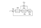
次に、実施の形態1にかかる速度制御装置1について図1を用いて説明する。以下では、基本の形態にかかる速度制御装置900と異なる部分を中心に説明する。
Next, the
速度制御装置1は、推定器6、補正部3、積分器4、d軸電流指令修正器5、及び減算器7を備える。
The
推定器6は、d軸電流idを3相2相座標変換器29から受け、回転速度(モータ角速度)ωrを速度検出器24から受け、q軸電圧成分Vq’をq軸電流制御器37から受ける。推定器6は、d軸電流id、回転速度ωr、及びq軸電圧成分Vq’に基づいて、q軸過渡電圧飽和量ΔVqtを推定して補正部3へ出力する。
Estimator 6 receives the d-axis current i d from three-phase to two-phase coordinate
補正部3は、q軸電圧飽和量ΔVqを減算器2から受け、q軸過渡電圧飽和量ΔVqtを推定器6から受ける。補正部3は、過渡電圧飽和量の影響が減少するように、q軸電圧飽和量ΔVqをq軸過渡電圧飽和量ΔVqtで補正する。例えば、補正部3は、q軸電圧飽和量ΔVqからq軸過渡電圧飽和量ΔVqtを減算する。そして、補正部3は、補正されたq軸電圧飽和量ΔVqsを積分器4へ出力する。
積分器4は、q軸電圧飽和量ΔVqsを保持しながら積分し、積分されたq軸電圧飽和量ΔVqs’をd軸電流指令修正器5へ出力する。 The integrator 4 integrates while maintaining a q-axis voltage saturation amount [Delta] V qs, and outputs the integrated q-axis voltage saturation amount [Delta] V qs' to d-axis current command correction unit 5.
d軸電流指令修正器5は、積分されたq軸電圧飽和量ΔVqs’を積分器4から受け、dq軸座標の回転角速度ωを回転角速度演算器40から受ける。d軸電流指令修正器5は、q軸電圧飽和量ΔVqs’とdq軸座標の回転角速度ωとに基づいて、d軸電流指令修正量Δidを求めて減算器7へ出力する。
The d-axis current command corrector 5 receives the integrated q-axis voltage saturation amount ΔV qs ′ from the integrator 4 and receives the rotation angular velocity ω of the dq-axis coordinates from the rotation
減算器7は、d軸電流指令id *をd軸電流指令生成部46から受け、d軸電流指令修正量Δidをd軸電流指令修正器5から受ける。減算器7は、d軸電流指令id *からd軸電流指令修正量Δidを減算してd軸電流指令id *を修正し、修正結果としてd軸電流修正指令id * cmdを減算器34へ出力する。
Subtracter 7 receives the d-axis current command i d * and d-axis current
次に、補正部3の構成について図2を用いて説明する。図2は、補正部3の構成を示す図である。
Next, the configuration of the
補正部3は、例えば、減算器3aを有する。減算器3aは、q軸電圧飽和量ΔVqを減算器2(図1参照)から受け、q軸過渡電圧飽和量ΔVqtを推定器6(図1参照)から受ける。減算器3aは、q軸電圧飽和量ΔVqからq軸過渡電圧飽和量ΔVqtを減算し、減算結果をq軸電圧飽和量ΔVqsとして積分器4(図1参照)へ出力する。
The
次に、推定器6の構成について図3を用いて説明する。図3は、推定器6の構成を示す図である。 Next, the configuration of the estimator 6 will be described with reference to FIG. FIG. 3 is a diagram illustrating a configuration of the estimator 6.
推定器6は、乗除算器6a、乗算器6g、加算器6b、乗算器6c、減算器6d、リミット6e、及び減算器6fを有する。乗除算器6aは、磁束鎖交数φを極対数Pmで割った値「φ/Pm」を求めて加算器6bへ出力する。乗算器6gは、d軸電流idにd軸インダクタンスLdを乗算した値「idLd」を求めて加算器6bへ出力する。加算器6bは、値「φ/Pm」と値「idLd」とを加算した値「φ/Pm+idLd」を乗算器6cへ出力する。乗算器6cは、値「φ/Pm+idLd」に回転速度(モータ電気角速度)ωreを乗算した値「ωre(φ/Pm+idLd)」を減算器6dへ出力する。減算器6dは、q軸電圧成分(トルク軸電圧指令)Vq’から値「ωre(φ/Pm+idLd)」を減算した値「(R+sLq)iq」をq軸過渡電圧Vqs’として求めてリミット6e及び減算器6fへ出力する。リミット6eは、減算器6dから出力されるq軸過渡電圧Vqs’を所定の範囲内に制限し、その結果をq軸過渡電圧指令Vqs *として出力する。減算器6fは、q軸過渡電圧Vqs’からq軸過渡電圧指令Vqs *を減算してq軸過渡電圧飽和量ΔVqtを求めて出力する。
The estimator 6 includes a multiplier /
以上のように、実施の形態1では、補正部3が、q軸電圧飽和量ΔVqをq軸過渡電圧飽和量ΔVqtで補正する。これにより、d軸電流指令修正量Δidを求めるためのq軸電圧飽和量に対して過渡電圧飽和量の影響が減少するように補正できるので、d軸電流指令修正量Δidが過剰に大きくなることを抑制でき、d軸電流(磁束軸電流)の過補償を抑制できる。この結果、交流電動機のモータトルクの減衰を低減できる。
As described above, in the first embodiment, the
例えば、図4に示すように、モータ速度が変化する際(例えば、一点鎖線で囲った領域)におけるq軸電流iqの減衰は、過渡電圧飽和量で補正しない場合(図13参照)に比べて、低減できる。これにより、モータ速度が変化する際に、交流電動機のモータトルクの減衰を低減できる。 For example, as shown in FIG. 4, when the motor speed changes (e.g., surrounded by regions by a dashed line) the attenuation of the q-axis current i q in is compared with the case of no correction in a transient voltage saturation amount (see FIG. 13) Can be reduced. Thereby, when the motor speed changes, the attenuation of the motor torque of the AC motor can be reduced.
また、実施の形態1では、補正部3が、q軸電圧飽和量ΔVqからq軸過渡電圧飽和量ΔVqtを減算することにより、q軸電圧飽和量ΔVqをq軸過渡電圧飽和量ΔVqtで補正する。これにより、補正部3を図2に示すように簡易な構成で実現できる。
In the first embodiment, the
なお、速度制御装置100は、推定器6(図3参照)に代えて、図5に示すような推定器106を有していても良い。図5に示す推定器106は、q軸電流指令iq *をq軸電流リミッタ42から受け、q軸電流指令iq *に基づいてq軸過渡電圧飽和量ΔVqtを推定して補正部3へ出力する。
Note that the
具体的には、推定器106は、減算器106a、制御ゲイン106b、リミット106c、積分器106e、及び減算器106dを有する。減算器106aは、q軸電流指令iq *からq軸電流変化推定値Δiqを減算した値iq’を制御ゲイン106bへ出力する。制御ゲイン106bは、値iq’をゲイン(ωccLq)により増幅してその結果sLqiqをq軸過渡電圧Vqs’としてリミット106c及び減算器106dへ出力する。リミット106cは、制御ゲイン106bから出力されるq軸過渡電圧Vqs’を所定の範囲内に制限し、その結果をq軸過渡電圧指令Vqs *として減算器106d及び積分器106eへ出力する。積分器106eは、q軸過渡電圧指令Vqs *を積分するとともに所定の係数(1/Lq)をかけてq軸電流変化推定値Δiqを求めて減算器106aへ出力する。減算器106dは、q軸過渡電圧Vqs’からq軸過渡電圧指令Vqs *を減算してq軸過渡電圧飽和量ΔVqtを求めて出力する。
Specifically, the
実施の形態2.
次に、実施の形態2にかかる速度制御装置200について説明する。以下では、実施の形態1と異なる部分を中心に説明する。
Embodiment 2. FIG.
Next, the
実施の形態1では、q軸電圧飽和量ΔVqにおける過渡電圧成分の割合が無視できないぐらい大きくなった場合を想定して、補正部3が、q軸電圧飽和量ΔVqからq軸過渡電圧飽和量ΔVqtを減算することにより、q軸電圧飽和量ΔVqをq軸過渡電圧飽和量ΔVqtで補正している。
In the first embodiment, assuming that the ratio of the transient voltage component in the q-axis voltage saturation amount ΔV q increases to a degree that cannot be ignored, the
一方、q軸電圧飽和量ΔVqにおける過渡電圧成分の割合が無視できない度合は、数式7に示されるように、q軸インダクタンスLqに依存するものと考えられる。そこで、実施の形態2では、q軸インダクタンスLqがどの程度大きいかに応じて、q軸過渡電圧飽和量ΔVqtによる補正量を可変にする。 On the other hand, the degree to which the ratio of the transient voltage component in the q-axis voltage saturation amount ΔV q cannot be ignored is considered to depend on the q-axis inductance L q as shown in Equation 7. Therefore, in the second embodiment, the correction amount by the q-axis transient voltage saturation amount ΔV qt is made variable according to how large the q-axis inductance L q is.
具体的には、速度制御装置200における補正部203は、図6に示すように、係数器203c、乗算器203b、及び減算器203aを有する。
Specifically, the
係数器203cは、q軸インダクタンスLqの値に応じて係数Kの値を決定する。
例えば、係数器203cは、q軸インダクタンスLqの複数の値と係数Kの複数の値とが対応付けられた係数テーブルを有している。例えば、係数器203cは、係数テーブルを参照することにより、q軸インダクタンスLqがインダクタンス値Lq1である場合、係数Kを値K1(例えば、=1)に決定し、q軸インダクタンスLqがインダクタンス値Lq2(<Lq1)である場合、係数Kを値K2(<K1,>0)に決定し、q軸インダクタンスLqがインダクタンス値Lq3(<Lq3)である場合、係数Kを値K3(<K2,>0)に決定する。
For example, the
あるいは、例えば、係数器203cは、q軸インダクタンスLqの閾値Lqthを有している。例えば、係数器203cは、q軸インダクタンスLqの値と閾値Lqthとを比較し、q軸インダクタンスLqの値が閾値Lqthより大きい場合、係数Kを値K1(例えば、=1)に決定し、q軸インダクタンスLqの値が閾値Lqth以下である場合、係数Kを値K2(<K1,>0)に決定する。
Alternatively, for example, the
乗算器203bは、q軸過渡電圧飽和量ΔVqtを推定器6から受け、係数Kを係数器203cから受ける。乗算器203bは、q軸過渡電圧飽和量ΔVqtに係数Kを乗算し、その結果を補正量KΔVqtとして減算器203aへ出力する。
減算器203aは、q軸電圧飽和量ΔVqを減算器2(図1参照)から受け、補正量KΔVqtを乗算器203bから受ける。減算器203aは、q軸電圧飽和量ΔVqから補正量KΔVqtを減算する。
The
以上のように、実施の形態2では、補正部203が、q軸インダクタンスが第1のインダクタンス値である場合、q軸過渡電圧飽和量に第1の係数をかけた第1の補正量をトルク軸電圧飽和量から減算し、q軸インダクタンスが第1のインダクタンス値より小さい第2のインダクタンス値である場合、q軸過渡電圧飽和量に第1の係数より小さい第2の係数をかけた第2の補正量をトルク軸電圧飽和量から減算する。これにより、q軸電圧飽和量ΔVqにおける過渡電圧成分の割合が無視できない度合に応じて、補正量を可変にするので、補正に伴う誤差の影響を低減できる。この結果、d軸電流(磁束軸電流)の過補償をさらに抑制できる。
As described above, in the second embodiment, when the q-axis inductance is the first inductance value, the
なお、速度制御装置200iは、q軸電流iqの時間的変化率がどの程度大きいかに応じて、q軸過渡電圧飽和量ΔVqtによる補正量を可変にしてもよい。具体的には、速度制御装置200iにおける補正部203iは、図7に示すように、演算部203di、係数器203ci、乗算器203b、及び減算器203aを有する。
Note that the
演算部203diは、q軸電流iqを3相2相座標変換器29から受ける。演算部203diは、q軸電流iqの時間的変化率を演算してその演算結果siqを係数器203ciへ出力する。
Calculation unit 203di receives the q-axis current i q from the three-phase to two-phase coordinate
係数器203ciは、q軸電流iqの時間的変化率siqの値に応じて係数Kの値を決定する。 The coefficient unit 203ci determines the value of the coefficient K according to the value of the temporal change rate si q of the q-axis current i q .
例えば、係数器203ciは、q軸電流iqの時間的変化率siqの複数の値と係数Kの複数の値とが対応付けられた係数テーブルを有している。例えば、係数器203ciは、係数テーブルを参照することにより、q軸電流iqの時間的変化率siqが変化率siq1である場合、係数Kを値K1(例えば、=1)に決定し、q軸電流iqの時間的変化率siqが変化率siq2(<siq1)である場合、係数Kを値K2(<K1,>0)に決定し、q軸電流iqの時間的変化率siqが変化率siq3(<siq2)である場合、係数Kを値K3(<K2,>0)に決定する。 For example, the coefficient unit 203ci has a coefficient table in which a plurality of values of the temporal change rate si q of the q-axis current i q and a plurality of values of the coefficient K are associated with each other. For example, the coefficient unit 203ci is determined by referring to the coefficient table, when the temporal change rate si q of the q-axis current i q is the rate of change si q1, the coefficient K value K 1 (e.g., = 1) When the temporal change rate si q of the q-axis current i q is the change rate si q2 (<si q1 ), the coefficient K is determined as the value K 2 (<K 1 ,> 0), and the q-axis current i When the temporal change rate si q of q is the change rate si q3 (<si q2 ), the coefficient K is determined to be a value K 3 (<K 2 ,> 0).
あるいは、例えば、係数器203ciは、q軸電流iqの時間的変化率siqの閾値siqthを有している。例えば、係数器203ciは、q軸電流iqの時間的変化率siqの値と閾値siqthとを比較し、q軸電流iqの時間的変化率siqの値が閾値siqthより大きい場合、係数Kを値K1(例えば、=1)に決定し、q軸電流iqの時間的変化率siqの値が閾値siqth以下である場合、係数Kを値K2(<K1,>0)に決定する。 Alternatively, for example, the coefficient unit 203ci has a threshold value si qth of the temporal change rate si q of the q-axis current i q . For example, the coefficient unit 203ci compares the value with a threshold value si qth temporal change rate si q of the q-axis current i q, the value is greater than the threshold value si qth temporal change rate si q of the q-axis current i q If the coefficient K is determined to be a value K 1 (eg, = 1), and the value of the temporal change rate si q of the q-axis current i q is equal to or less than the threshold value si qth , the coefficient K is set to a value K 2 (<K 1 ,> 0).
このように、補正部203iが、q軸電流の時間的変化率が第1の変化率である場合、q軸過渡電圧飽和量に第1の係数をかけた第1の補正量をトルク軸電圧飽和量から減算し、q軸電流の時間的変化率が第1の変化率より小さい第2の変化率である場合、q軸過渡電圧飽和量に第1の係数より小さい第2の係数をかけた第2の補正量をq軸電圧飽和量から減算する。これによっても、q軸電圧飽和量ΔVqにおける過渡電圧成分の割合が無視できない度合に応じて、補正量を可変にするので、補正に伴う誤差の影響を低減できる。この結果、d軸電流(磁束軸電流)の過補償をさらに抑制できる。
As described above, when the temporal change rate of the q-axis current is the first change rate, the
あるいは、速度制御装置200iは、q軸インダクタンスLqとq軸電流iqの時間的変化率との積がどの程度大きいかに応じて、q軸過渡電圧飽和量ΔVqtによる補正量を可変にしてもよい。具体的には、速度制御装置200iにおける補正部203iは、図7に示すように、演算部203di、係数器203ci、乗算器203b、及び減算器203aを有する。
Alternatively, the
演算部203diは、q軸電流iqを3相2相座標変換器29から受ける。演算部203diは、q軸電流iqの時間的変化率を演算し、さらにq軸インダクタンスLqとq軸電流iqの時間的変化率との積を演算し、その演算結果sLqiqを係数器203ciへ出力する。
Calculation unit 203di receives the q-axis current i q from the three-phase to two-phase coordinate
係数器203ciは、q軸インダクタンスLqとq軸電流iqの時間的変化率との積sLqiqの値に応じて係数Kの値を決定する。 The coefficient unit 203ci determines the value of the coefficient K according to the value of the product sL q i q of the q-axis inductance L q and the temporal change rate of the q-axis current i q .
例えば、係数器203ciは、積sLqiqの複数の値と係数Kの複数の値とが対応付けられた係数テーブルを有している。例えば、係数器203ciは、係数テーブルを参照することにより、積sLqiqが値sLq1iq1である場合、係数Kを値K1(例えば、=1)に決定し、積sLqiqが値sLq2iq2(<sLq1iq1)である場合、係数Kを値K2(<K1,>0)に決定し、積sLqiqが値sLq3iq3(<sLq2iq2)である場合、係数Kを値K3(<K2,>0)に決定する。 For example, the coefficient unit 203ci has a coefficient table in which a plurality of values of the product sL q i q and a plurality of values of the coefficient K are associated with each other. For example, when the product sL q i q is the value sL q1 i q1 by referring to the coefficient table, the coefficient unit 203ci determines the coefficient K as the value K 1 (for example, = 1), and the product sL q i If q is the value sL q2 i q2 (<sL q1 i q1 ), the coefficient K is determined to be the value K 2 (<K 1 ,> 0) and the product sL q i q is the value sL q3 i q3 (<sL If q2 i q2 ), the coefficient K is determined to be the value K 3 (<K 2 ,> 0).
あるいは、例えば、係数器203ciは、積sLqiqの閾値sLqthiqthを有している。例えば、係数器203ciは、積sLqiqの値と閾値sLqthiqthとを比較し、積sLqiqの値が閾値sLqthiqthより大きい場合、係数Kを値K1(例えば、=1)に決定し、積sLqiqの値が閾値sLqthiqth以下である場合、係数Kを値K2(<K1,>0)に決定する。 Alternatively, for example, the coefficient unit 203ci has a threshold value sL qth i qth of the product sL q i q . For example, the coefficient unit 203ci compares the value with a threshold sL qth i qth product sL q i q, if the value of the product sL q i q is greater than the threshold sL qth i qth, the value K 1 coefficient K (e.g., = 1, and if the value of the product sL q i q is less than or equal to the threshold sL qth i qth , the coefficient K is determined to be a value K 2 (<K 1 ,> 0).
このように、補正部203iが、q軸インダクタンスとq軸電流の時間的変化率との積が第1の値である場合、q軸過渡電圧飽和量に第1の係数をかけた第1の補正量をトルク軸電圧飽和量から減算し、q軸インダクタンスとq軸電流の時間的変化率との積が第1の値より小さい第2の値である場合、q軸過渡電圧飽和量に第1の係数より小さい第2の係数をかけた第2の補正量をq軸電圧飽和量から減算する。これによっても、q軸電圧飽和量ΔVqにおける過渡電圧成分の割合が無視できない度合に応じて、補正量を可変にするので、補正に伴う誤差の影響を低減できる。この結果、d軸電流(磁束軸電流)の過補償をさらに抑制できる。
As described above, when the product of the q-axis inductance and the temporal change rate of the q-axis current is the first value, the
実施の形態3.
次に、実施の形態3にかかる速度制御装置300について説明する。以下では、実施の形態1と異なる部分を中心に説明する。
Next, the
実施の形態1では、q軸電圧の変動量が大きいことから、q軸電圧の飽和量に基づいてd軸電流を修正(補正)する場合について着目し、補正部3が、q軸電圧飽和量ΔVqをq軸過渡電圧飽和量ΔVqtで補正している。
In
一方、q軸電圧ほどではないにしてもd軸電圧も変動している。そこで、実施の形態3では、d軸電圧の飽和量に基づいてq軸電流を修正(補正)する場合についても、補正部313が、d軸電圧飽和量ΔVdをd軸過渡電圧飽和量ΔVdtで補正するようにする。
On the other hand, the d-axis voltage also fluctuates if not as high as the q-axis voltage. Therefore, in the third embodiment, a case of correcting the q-axis current based on the saturation amount of the d-axis voltage (correction) also, the correcting
具体的には、速度制御装置300は、推定器316、補正部313、積分器314、q軸電流指令修正器315、及び減算器317を備える。
Specifically, the
推定器316は、q軸電流iqを3相2相座標変換器29から受け、回転速度(モータ電気角速度)ωrを速度検出器24から受け、d軸電圧成分Vd’をd軸電流制御器35から受ける。推定器316は、q軸電流iq、回転速度ωr、及びd軸電圧成分Vd’に基づいて、d軸過渡電圧飽和量ΔVdtを推定して補正部313へ出力する。
The
補正部313は、d軸電圧飽和量ΔVdを減算器312から受け、d軸過渡電圧飽和量ΔVdtを推定器316から受ける。補正部313は、過渡電圧飽和量の影響が減少するように、d軸電圧飽和量ΔVdをd軸過渡電圧飽和量ΔVdtで補正する。例えば、補正部313は、d軸電圧飽和量ΔVdからd軸過渡電圧飽和量ΔVdtを減算する。そして、補正部313は、補正されたd軸電圧飽和量ΔVdsを積分器314へ出力する。
積分器314は、d軸電圧飽和量ΔVdsを保持しながら積分し、積分されたd軸電圧飽和量ΔVds’をq軸電流指令修正器315へ出力する。
The
q軸電流指令修正器315は、積分されたd軸電圧飽和量ΔVds’を積分器314から受け、dq軸座標の回転角速度ωを回転角速度演算器40から受ける。q軸電流指令修正器315は、d軸電圧飽和量ΔVds’とdq軸座標の回転角速度ωとに基づいて、q軸電流指令修正量Δiqを求めて減算器317へ出力する。
The q-axis
減算器317は、q軸電流指令iq *をq軸電流リミッタ42から受け、q軸電流指令修正量Δiqをq軸電流指令修正器315から受ける。減算器317は、q軸電流指令iq *からq軸電流指令修正量Δiqを減算してq軸電流指令iq *を修正し、修正結果としてq軸電流修正指令iq * cmdを減算器36へ出力する。
以上のように、実施の形態3では、補正部313が、d軸電圧飽和量ΔVdをd軸過渡電圧飽和量ΔVdtで補正する。これにより、q軸電流指令修正量Δiqを求めるためのd軸電圧飽和量に対して過渡電圧飽和量の影響が減少するように補正できるので、q軸電流指令修正量Δiqが過剰に大きくなることを抑制でき、q軸電流(トルク軸電流)の過補償を抑制できる。この結果、交流電動機のモータトルクの減衰をさらに低減できる。
As described above, in the third embodiment, the
なお、補正部313の内部構成は、実施の形態1と同様でもよいし、実施の形態2と同様でも良い。また、推定器316の内部構成は、図9に示す構成でもよいし、図10に示す構成でもよい。
Note that the internal configuration of the
以上のように、本発明にかかる速度制御装置は、交流電動機の速度の制御に有用である。 As described above, the speed control device according to the present invention is useful for controlling the speed of the AC motor.
1、100、200、200i、300、900 速度制御装置
2 減算器
3、203、203i 補正部
4、904 積分器
5、905 d軸電流指令修正器
6、106 推定器
7、907 減算器
312 減算器
313 補正部
314 積分器
315 q軸電流指令修正器
316 推定器
317 減算器
1, 100, 200, 200i, 300, 900 Speed control device 2
Claims (6)
トルク軸電流を比例積分制御するトルク軸電流制御器から出力されるトルク軸電圧成分を所定の値以下になるように制限するトルク軸電圧リミッタと、
前記トルク軸電流制御器から出力されるトルク軸電圧成分と前記トルク軸電圧リミッタから出力されるトルク軸電圧指令とからトルク軸電圧飽和量を求める第1の減算器と、
前記求められたトルク軸電圧飽和量を、推定器により推定されたトルク軸過渡電圧飽和量で補正する補正部と、
前記補正されたトルク軸電圧飽和量を保持する第1の積分器と、
前記保持されたトルク軸電圧飽和量と直交2軸座標の回転角速度とから磁束軸電流指令修正量を求めて出力する磁束軸電流指令修正器と、
磁束軸電流指令から前記磁束軸電流指令修正量を減算し磁束軸電流指令修正指令を求めて出力する第2の減算器と、
を備えたことを特徴とする交流電動機の速度制御装置。 A speed control device for an AC motor having a current controller that performs proportional-integral control on a magnetic flux axis current and a torque axis current, which are two components on orthogonal two-axis coordinates for rotating the current of the AC motor,
A torque axis voltage limiter that limits the torque axis voltage component output from the torque axis current controller that performs proportional integral control of the torque axis current so as to be a predetermined value or less;
A first subtractor for obtaining a torque axis voltage saturation amount from a torque axis voltage component output from the torque axis current controller and a torque axis voltage command output from the torque axis voltage limiter;
A correction unit that corrects the obtained torque axis voltage saturation amount with the torque axis transient voltage saturation amount estimated by the estimator;
A first integrator for holding the corrected torque shaft voltage saturation amount;
A magnetic flux axis current command corrector that calculates and outputs a magnetic flux axis current command correction amount from the held torque axis voltage saturation amount and the rotational angular velocity of the orthogonal two-axis coordinate;
A second subtractor for subtracting the magnetic flux axis current command correction amount from the magnetic flux axis current command to obtain and output a magnetic flux axis current command correction command;
An AC motor speed control device comprising:
ことを特徴とする請求項1に記載の交流電動機の速度制御装置。 2. The AC motor speed control device according to claim 1, wherein the correction unit subtracts the torque axis transient voltage saturation amount from the obtained torque axis voltage saturation amount.
ことを特徴とする請求項1に記載の交流電動機の速度制御装置。 When the torque axis inductance is the first inductance value, the correction unit subtracts a first correction amount obtained by multiplying the torque axis transient voltage saturation amount by a first coefficient from the obtained torque axis voltage saturation amount. When the torque axis inductance is a second inductance value smaller than the first inductance value, a second correction amount obtained by multiplying the torque axis transient voltage saturation amount by a second coefficient smaller than the first coefficient. The speed control device for an AC motor according to claim 1, wherein: is subtracted from the obtained torque shaft voltage saturation amount.
ことを特徴とする請求項1に記載の交流電動機の速度制御装置。 When the temporal change rate of the torque axis current is the first change rate, the correction unit applies a first correction amount obtained by multiplying the torque axis transient voltage saturation amount by a first coefficient to the obtained torque axis. When the torque shaft current subtraction is subtracted from the voltage saturation amount and the temporal change rate of the torque shaft current is a second change rate smaller than the first change rate, the torque axis transient voltage saturation amount is a second smaller than the first coefficient. The AC motor speed control device according to claim 1, wherein a second correction amount multiplied by a coefficient is subtracted from the obtained torque shaft voltage saturation amount.
ことを特徴とする請求項1に記載の交流電動機の速度制御装置。 When the product of the torque axis inductance and the temporal change rate of the torque axis current is a first value, the correction unit calculates a first correction amount obtained by multiplying the torque axis transient voltage saturation amount by a first coefficient. When the product of the torque axis inductance and the torque axis current is a second value smaller than the first value, the torque axis transient voltage saturation is subtracted from the obtained torque axis voltage saturation amount. The AC motor speed control according to claim 1, wherein a second correction amount obtained by multiplying an amount by a second coefficient smaller than the first coefficient is subtracted from the obtained torque shaft voltage saturation amount. apparatus.
前記磁束軸電流制御器から出力される磁束軸電圧成分と前記磁束軸電圧リミッタから出力される磁束軸電圧指令とから磁束軸電圧飽和量を求める第3の減算器と、
前記求められた磁束軸電圧飽和量を、第2の推定器により推定された磁束軸過渡電圧飽和量で補正する第2の補正部と、
前記補正された磁束軸電圧飽和量を保持する第2の積分器と、
前記保持された磁束軸電圧飽和量と直交2軸座標の回転角速度とからトルク軸電流指令修正量を求めて出力するトルク軸電流指令修正器と、
トルク軸電流指令から前記トルク軸電流指令修正量を減算しトルク軸電流指令修正指令を求めて出力する第4の減算器と、
をさらに備えた
ことを特徴とする請求項1から5のいずれか1項に記載の交流電動機の速度制御装置。 A magnetic flux axis voltage limiter that limits the magnetic flux axis voltage component output from the magnetic flux axis current controller that performs proportional integral control of the magnetic flux axis current to be a predetermined value or less;
A third subtractor for obtaining a flux axis voltage saturation amount from a flux axis voltage component output from the flux axis current controller and a flux axis voltage command output from the flux axis voltage limiter;
A second correction unit that corrects the obtained magnetic flux axis voltage saturation amount with the magnetic flux axis transient voltage saturation amount estimated by the second estimator;
A second integrator for holding the corrected magnetic flux axis voltage saturation amount;
A torque axis current command corrector that calculates and outputs a torque axis current command correction amount from the held magnetic flux axis voltage saturation amount and the rotational angular velocity of the orthogonal biaxial coordinates;
A fourth subtractor for subtracting the torque axis current command correction amount from the torque axis current command to obtain and output a torque axis current command correction command;
The speed control device for an AC motor according to any one of claims 1 to 5, further comprising:
Priority Applications (2)
| Application Number | Priority Date | Filing Date | Title |
|---|---|---|---|
| JP2011191978A JP5409727B2 (en) | 2011-09-02 | 2011-09-02 | AC motor speed control device |
| CN201210009176.4A CN102983804B (en) | 2011-09-02 | 2012-01-12 | The speed control unit of alternating current motor |
Applications Claiming Priority (1)
| Application Number | Priority Date | Filing Date | Title |
|---|---|---|---|
| JP2011191978A JP5409727B2 (en) | 2011-09-02 | 2011-09-02 | AC motor speed control device |
Publications (2)
| Publication Number | Publication Date |
|---|---|
| JP2013055788A JP2013055788A (en) | 2013-03-21 |
| JP5409727B2 true JP5409727B2 (en) | 2014-02-05 |
Family
ID=47857596
Family Applications (1)
| Application Number | Title | Priority Date | Filing Date |
|---|---|---|---|
| JP2011191978A Active JP5409727B2 (en) | 2011-09-02 | 2011-09-02 | AC motor speed control device |
Country Status (2)
| Country | Link |
|---|---|
| JP (1) | JP5409727B2 (en) |
| CN (1) | CN102983804B (en) |
Families Citing this family (14)
| Publication number | Priority date | Publication date | Assignee | Title |
|---|---|---|---|---|
| WO2014167678A1 (en) * | 2013-04-10 | 2014-10-16 | 三菱電機株式会社 | Control device for permanent magnet motor |
| JP6260502B2 (en) * | 2014-09-16 | 2018-01-17 | 株式会社デンソー | Motor control device |
| CN104393807B (en) * | 2014-11-07 | 2017-09-22 | 美的集团股份有限公司 | The control method and its control system of motor |
| US10103667B2 (en) * | 2015-05-28 | 2018-10-16 | Steering Solutions Ip Holding Corporation | Motor control anti-windup and voltage saturation design for electric power steering |
| CN104901598B (en) * | 2015-06-24 | 2017-07-28 | 广东威灵电机制造有限公司 | Motor driver, method and motor |
| CN104901593B (en) * | 2015-06-24 | 2017-10-24 | 广东威灵电机制造有限公司 | Motor driver, method and motor |
| US10476423B2 (en) | 2015-08-04 | 2019-11-12 | Mitsubishi Electric Corporation | Synchronous motor control device, compressor drive system, and air conditioner |
| CN107659230B (en) * | 2016-07-26 | 2021-01-15 | 广州极飞科技有限公司 | Motor vector control method and device and aircraft |
| US10008967B2 (en) * | 2016-10-25 | 2018-06-26 | Microchip Technology Inc. | Closed loop flux weakening for permanent magnet synchronous motors |
| US10411634B2 (en) * | 2017-11-28 | 2019-09-10 | Steering Solutions Ip Holding Corporation | Controller anti-windup for permanent magnet synchronous machines |
| CN110138285B (en) * | 2019-06-13 | 2022-04-01 | 安徽首智新能源科技有限公司 | Permanent magnet synchronous motor speed-up control method and system |
| CN110768602B (en) * | 2019-10-31 | 2021-05-25 | 广东美的制冷设备有限公司 | Torque compensation method, device, air conditioner, and storage medium |
| CN112187129B (en) * | 2020-12-01 | 2021-04-02 | 深圳市兆威机电股份有限公司 | Motor control method, device, device and storage medium |
| CN119362921B (en) * | 2024-12-26 | 2025-03-25 | 北京航空航天大学 | A synchronous control method based on mapping the difference of dual-axis mass damping into unbalanced output |
Family Cites Families (5)
| Publication number | Priority date | Publication date | Assignee | Title |
|---|---|---|---|---|
| JP3679246B2 (en) * | 1998-04-24 | 2005-08-03 | 潔 大石 | AC motor speed control device |
| CN1212701C (en) * | 2001-07-13 | 2005-07-27 | 三菱电机株式会社 | AC motor speed control device |
| JP4007345B2 (en) * | 2004-06-29 | 2007-11-14 | アイシン・エィ・ダブリュ株式会社 | Electric drive control device, electric drive control method, and program |
| JP4715576B2 (en) * | 2006-03-22 | 2011-07-06 | アイシン・エィ・ダブリュ株式会社 | Electric drive control device and electric drive control method |
| JP5322534B2 (en) * | 2008-08-26 | 2013-10-23 | 三菱電機株式会社 | Control device and motor control device |
-
2011
- 2011-09-02 JP JP2011191978A patent/JP5409727B2/en active Active
-
2012
- 2012-01-12 CN CN201210009176.4A patent/CN102983804B/en not_active Expired - Fee Related
Also Published As
| Publication number | Publication date |
|---|---|
| CN102983804A (en) | 2013-03-20 |
| CN102983804B (en) | 2015-08-26 |
| JP2013055788A (en) | 2013-03-21 |
Similar Documents
| Publication | Publication Date | Title |
|---|---|---|
| JP5409727B2 (en) | AC motor speed control device | |
| TWI654827B (en) | Converter control device and motor driving system | |
| JP5257365B2 (en) | Motor control device and control method thereof | |
| JP5073063B2 (en) | Control device for permanent magnet synchronous motor | |
| JP5351859B2 (en) | Vector control device and motor control system | |
| JP6672902B2 (en) | Motor control device | |
| JP5877733B2 (en) | Electric motor control device | |
| WO2013084461A1 (en) | Electric motor control device | |
| JP2014027742A (en) | Motor control device | |
| WO2016121237A1 (en) | Inverter control device and motor drive system | |
| JP6115392B2 (en) | Motor control device | |
| JP2011050178A (en) | Motor control device and generator control device | |
| JP7363524B2 (en) | Sensorless motor control device | |
| JP2018057170A (en) | AC motor control device | |
| JP2019213309A (en) | Control method of winding field magnetic type synchronous motor, and control device | |
| JP6769050B2 (en) | Motor control device | |
| JP2013150498A (en) | Controller and control method of synchronous motor | |
| JP5648310B2 (en) | Synchronous motor control device and synchronous motor control method | |
| JP6519149B2 (en) | Motor controller | |
| WO2016079791A1 (en) | Motor control device and motor control method | |
| JP5862690B2 (en) | Control device for motor drive device and motor drive system | |
| JP7251424B2 (en) | INVERTER DEVICE AND INVERTER DEVICE CONTROL METHOD | |
| JP7009861B2 (en) | Motor control device | |
| JP5517983B2 (en) | AC rotating machine control device | |
| JP5862691B2 (en) | Control device for motor drive device and motor drive system |
Legal Events
| Date | Code | Title | Description |
|---|---|---|---|
| A621 | Written request for application examination |
Free format text: JAPANESE INTERMEDIATE CODE: A621 Effective date: 20130614 |
|
| A977 | Report on retrieval |
Free format text: JAPANESE INTERMEDIATE CODE: A971007 Effective date: 20131002 |
|
| TRDD | Decision of grant or rejection written | ||
| A01 | Written decision to grant a patent or to grant a registration (utility model) |
Free format text: JAPANESE INTERMEDIATE CODE: A01 Effective date: 20131008 |
|
| A61 | First payment of annual fees (during grant procedure) |
Free format text: JAPANESE INTERMEDIATE CODE: A61 Effective date: 20131105 |
|
| R150 | Certificate of patent or registration of utility model |
Ref document number: 5409727 Country of ref document: JP Free format text: JAPANESE INTERMEDIATE CODE: R150 |
|
| R250 | Receipt of annual fees |
Free format text: JAPANESE INTERMEDIATE CODE: R250 |
|
| R250 | Receipt of annual fees |
Free format text: JAPANESE INTERMEDIATE CODE: R250 |
|
| R250 | Receipt of annual fees |
Free format text: JAPANESE INTERMEDIATE CODE: R250 |
|
| R250 | Receipt of annual fees |
Free format text: JAPANESE INTERMEDIATE CODE: R250 |
|
| R250 | Receipt of annual fees |
Free format text: JAPANESE INTERMEDIATE CODE: R250 |
|
| R250 | Receipt of annual fees |
Free format text: JAPANESE INTERMEDIATE CODE: R250 |
|
| R250 | Receipt of annual fees |
Free format text: JAPANESE INTERMEDIATE CODE: R250 |
|
| R250 | Receipt of annual fees |
Free format text: JAPANESE INTERMEDIATE CODE: R250 |
|
| R250 | Receipt of annual fees |
Free format text: JAPANESE INTERMEDIATE CODE: R250 |
|
| R250 | Receipt of annual fees |
Free format text: JAPANESE INTERMEDIATE CODE: R250 |