JP5407979B2 - Shift control device for automatic transmission - Google Patents
Shift control device for automatic transmission Download PDFInfo
- Publication number
- JP5407979B2 JP5407979B2 JP2010071248A JP2010071248A JP5407979B2 JP 5407979 B2 JP5407979 B2 JP 5407979B2 JP 2010071248 A JP2010071248 A JP 2010071248A JP 2010071248 A JP2010071248 A JP 2010071248A JP 5407979 B2 JP5407979 B2 JP 5407979B2
- Authority
- JP
- Japan
- Prior art keywords
- shift
- hold level
- accelerator opening
- automatic transmission
- actual accelerator
- Prior art date
- Legal status (The legal status is an assumption and is not a legal conclusion. Google has not performed a legal analysis and makes no representation as to the accuracy of the status listed.)
- Expired - Fee Related
Links
Images


Classifications
-
- F—MECHANICAL ENGINEERING; LIGHTING; HEATING; WEAPONS; BLASTING
- F16—ENGINEERING ELEMENTS AND UNITS; GENERAL MEASURES FOR PRODUCING AND MAINTAINING EFFECTIVE FUNCTIONING OF MACHINES OR INSTALLATIONS; THERMAL INSULATION IN GENERAL
- F16H—GEARING
- F16H61/00—Control functions within control units of change-speed- or reversing-gearings for conveying rotary motion ; Control of exclusively fluid gearing, friction gearing, gearings with endless flexible members or other particular types of gearing
- F16H61/02—Control functions within control units of change-speed- or reversing-gearings for conveying rotary motion ; Control of exclusively fluid gearing, friction gearing, gearings with endless flexible members or other particular types of gearing characterised by the signals used
- F16H61/0202—Control functions within control units of change-speed- or reversing-gearings for conveying rotary motion ; Control of exclusively fluid gearing, friction gearing, gearings with endless flexible members or other particular types of gearing characterised by the signals used the signals being electric
- F16H61/0204—Control functions within control units of change-speed- or reversing-gearings for conveying rotary motion ; Control of exclusively fluid gearing, friction gearing, gearings with endless flexible members or other particular types of gearing characterised by the signals used the signals being electric for gearshift control, e.g. control functions for performing shifting or generation of shift signal
- F16H61/0213—Control functions within control units of change-speed- or reversing-gearings for conveying rotary motion ; Control of exclusively fluid gearing, friction gearing, gearings with endless flexible members or other particular types of gearing characterised by the signals used the signals being electric for gearshift control, e.g. control functions for performing shifting or generation of shift signal characterised by the method for generating shift signals
-
- B—PERFORMING OPERATIONS; TRANSPORTING
- B60—VEHICLES IN GENERAL
- B60W—CONJOINT CONTROL OF VEHICLE SUB-UNITS OF DIFFERENT TYPE OR DIFFERENT FUNCTION; CONTROL SYSTEMS SPECIALLY ADAPTED FOR HYBRID VEHICLES; ROAD VEHICLE DRIVE CONTROL SYSTEMS FOR PURPOSES NOT RELATED TO THE CONTROL OF A PARTICULAR SUB-UNIT
- B60W30/00—Purposes of road vehicle drive control systems not related to the control of a particular sub-unit, e.g. of systems using conjoint control of vehicle sub-units
- B60W30/18—Propelling the vehicle
- B60W30/182—Selecting between different operative modes, e.g. comfort and performance modes
-
- F—MECHANICAL ENGINEERING; LIGHTING; HEATING; WEAPONS; BLASTING
- F16—ENGINEERING ELEMENTS AND UNITS; GENERAL MEASURES FOR PRODUCING AND MAINTAINING EFFECTIVE FUNCTIONING OF MACHINES OR INSTALLATIONS; THERMAL INSULATION IN GENERAL
- F16H—GEARING
- F16H59/00—Control inputs to control units of change-speed- or reversing-gearings for conveying rotary motion
- F16H59/60—Inputs being a function of ambient conditions
- F16H59/66—Road conditions, e.g. slope, slippery
- F16H2059/663—Road slope
-
- F—MECHANICAL ENGINEERING; LIGHTING; HEATING; WEAPONS; BLASTING
- F16—ENGINEERING ELEMENTS AND UNITS; GENERAL MEASURES FOR PRODUCING AND MAINTAINING EFFECTIVE FUNCTIONING OF MACHINES OR INSTALLATIONS; THERMAL INSULATION IN GENERAL
- F16H—GEARING
- F16H59/00—Control inputs to control units of change-speed- or reversing-gearings for conveying rotary motion
- F16H59/02—Selector apparatus
- F16H59/0204—Selector apparatus for automatic transmissions with means for range selection and manual shifting, e.g. range selector with tiptronic
-
- F—MECHANICAL ENGINEERING; LIGHTING; HEATING; WEAPONS; BLASTING
- F16—ENGINEERING ELEMENTS AND UNITS; GENERAL MEASURES FOR PRODUCING AND MAINTAINING EFFECTIVE FUNCTIONING OF MACHINES OR INSTALLATIONS; THERMAL INSULATION IN GENERAL
- F16H—GEARING
- F16H59/00—Control inputs to control units of change-speed- or reversing-gearings for conveying rotary motion
- F16H59/14—Inputs being a function of torque or torque demand
- F16H59/18—Inputs being a function of torque or torque demand dependent on the position of the accelerator pedal
Landscapes
- Engineering & Computer Science (AREA)
- General Engineering & Computer Science (AREA)
- Mechanical Engineering (AREA)
- Control Of Transmission Device (AREA)
Description
本発明は、自動変速モードと手動変速モードの切り替え可能な自動変速機の変速制御装置に関する。 The present invention relates to a shift control device for an automatic transmission capable of switching between an automatic shift mode and a manual shift mode.
近年、自動変速機においては、車両の状態(例えば、車速、スロットル開度等)に応じて自動的に変速を行う自動変速モードに加えて、運転者の手動操作に応じて変速を行う手動変速モードを設けたものがある。このような自動変速機における自動変速モードと手動変速モードの切り替えは、運転者の手動操作によって行われている。 In recent years, in an automatic transmission, in addition to an automatic shift mode that automatically shifts according to the state of the vehicle (for example, vehicle speed, throttle opening, etc.), manual shift that shifts according to a driver's manual operation Some have a mode. Switching between the automatic transmission mode and the manual transmission mode in such an automatic transmission is performed by a driver's manual operation.
例えば、特許文献1に記載の自動変速機の変速制御装置では、変速モード切替スイッチの切替信号に基づいて自動変速モードと手動変速モードとを選択的に切り替え可能であると共に、この自動変速モード中に、ステアリングに設けられたダウンシフト操作スイッチが操作されると手動変速モードに切り替え、その後、ステアリングに設けられたアップシフト操作スイッチが操作されると自動変速モードに復帰させるものが開示されている。これにより、運転者はステアリングから手を離すことなく、自動変速モードと手動変速モードの切り替えが可能となり、変速操作の操作性並びに安全性の向上を図ることができるというものである。
For example, in the shift control device for an automatic transmission described in
また、特許文献2に記載の自動変速機の変速制御装置では、車速とエンジンの負荷に応じて目標変速比を設定する自動変速制御手段と、ステアリングホイールに配設されるとともに、運転者の操作に応じてアップシフトを指令するアップシフト指令手段及びダウンシフトを指令するダウンシフト指令手段と、アップシフト指令手段またはダウンシフト指令手段からの信号に基づいて目標変速比を設定する手動変速制御手段と、自動変速制御手段と手動変速制御手段とを選択的に切り替える変速モード切替手段とを備え、変速モード切替手段は、アップシフト指令手段及びダウンシフト指令手段が同時に操作されたときに、自動変速モードとマニュアルモードを選択的に切り替えるものが開示されている。これにより、ハンドルから手を放すことなく変速モードの切り替えを行うことができるというものである。
In addition, in the shift control device for an automatic transmission described in
特許文献1、2に記載の自動変速機の変速制御装置では、手動変速(マニュアル)モードから自動変速モードへの切り替えは運転者が何らかの操作をする必要があるため、以下のような問題がある。例えば、運転者が自動変速モードへ戻すことを忘れたために不必要に低速段で走行を続けることがあるため、燃費が悪化するおそれがある。また、コーナー手前だけ手動でダウンシフトしエンジンブレーキを効かせて、コーナーを抜けた後は自動変速させたいような場合、運転者はコーナーを抜けた後に自動変速モードに戻すため必ず所定の操作を行う必要があるため、操作が煩わしい。
In the shift control device for an automatic transmission described in
また、特許文献1、2に記載の自動変速機の変速制御装置では、例えば、手動変速(マニュアル)モードにおいて高車速(例えば、自動変速モードの場合は5速段で走行するような車速)で低速段(例えば、2速段)にホールドしているような場面において、自動変速モードに切り替えると、2速段から一気に5速段まで変速してしまうため、以下のような問題がある。例えば、2速段で定常走行している場合、手動変速モードから自動変速モードへの切り替えにより5速段に変速されることで、エンジン回転数が急低下し、エンジントルクが急増加するため、アクセルの調整が必要となり、ドライバビリティ(Drivability)やフィーリングが悪化する。また、2速段で加速中の場合、手動変速モードから自動変速モードへの切り替えにより5速段に変速されることで、急激に駆動力が無くなり、加速力が急減するため、ドライバビリティが悪化する。また、2速段で減速(エンジンブレーキ)中の場合、手動変速モードから自動変速モードへの切り替えにより5速段に変速されることで、急激にエンジンブレーキが無くなり、減速力が急減するため、ドライバビリティが悪化する。
In the shift control device for an automatic transmission described in
また、特許文献1、2に記載の自動変速機の変速制御装置では、自動変速モードと手動変速(マニュアル)モードの両方の制御を兼ね備える必要があるため、制御が複雑になる。
Further, in the shift control device for an automatic transmission described in
また、特許文献1に記載の自動変速機の変速制御装置では、アップシフト操作スイッチの操作は自動変速モードへの切り替えとなるため、手動変速モードのままアップシフトすることができず、利便性が悪い。
Further, in the shift control device for an automatic transmission described in
本発明の主な課題は、操作性、燃費、ドライバビリティ、利便性の向上、及び制御の簡素化を図ることができる自動変速モードと手動変速モードの切り替え可能な自動変速機の変速制御装置を提供することである。 A main object of the present invention is to provide a shift control device for an automatic transmission capable of switching between an automatic shift mode and a manual shift mode, which can improve operability, fuel consumption, drivability, convenience, and simplification of control. Is to provide.
本発明の一視点においては、自動変速機の変速制御装置において、少なくとも運転者の操作に応じて、変速段を維持する所定の値を示すシフトホールドレベルを演算するシフトホールドレベル演算部と、前記シフトホールドレベル演算部で演算された前記シフトホールドレベルに基づいて自動変速機を変速制御処理する変速処理部と、を備え、前記シフトホールドレベルは、完全な自動変速状態を示す0%から完全な手動変速状態を示す100%の間で連続的に更新されることを特徴とする。 In one aspect of the present invention, in a shift control device of an automatic transmission, a shift hold level calculation unit that calculates a shift hold level indicating a predetermined value for maintaining a gear position at least according to an operation of a driver, A shift processing unit that performs shift control processing on the automatic transmission based on the shift hold level calculated by the shift hold level calculation unit, and the shift hold level is from 0% indicating a complete automatic shift state to a complete shift level. It is continuously updated between 100% indicating the manual shift state .
本発明の前記自動変速機の変速制御装置において、前記シフトホールドレベル演算部は、シフトスイッチ又はシフトレバーでON操作されたときに前記シフトホールドレベルを強制的に100%に変更するように演算し、前記変速処理部は、前記シフトスイッチ又は前記シフトレバーでON操作されたときに自動変速機を変速制御処理することが好ましい。 In the shift control device for an automatic transmission according to the present invention, the shift hold level calculation unit calculates to forcibly change the shift hold level to 100% when an ON operation is performed by a shift switch or a shift lever. The shift processing unit preferably performs a shift control process on the automatic transmission when the shift switch or the shift lever is turned ON.
本発明の前記自動変速機の変速制御装置において、前記シフトホールドレベル演算部は、実アクセル開度が閾値以上の状態では、前記シフトホールドレベルが0%より大きいときに、前記シフトホールドレベルを0%側に変更するように演算し、実アクセル開度が前記閾値未満の状態では、前記シフトホールドレベルが0%より大きく100%より小さいときに、前記シフトホールドレベルを100%側に変更するように演算することが好ましい。 In the shift control device for an automatic transmission according to the present invention, the shift hold level calculation unit sets the shift hold level to 0 when the actual accelerator opening is greater than or equal to a threshold value and the shift hold level is greater than 0%. When the actual accelerator opening is less than the threshold value, the shift hold level is changed to 100% when the shift hold level is greater than 0% and less than 100%. It is preferable to calculate to.
本発明の前記自動変速機の変速制御装置において、前記シフトホールドレベル演算部は、実アクセル開度が閾値以上の状態では、前記シフトホールドレベルが0%より大きいときに、前記実アクセル開度の変化量に応じて、前記シフトホールドレベルを変更するように演算し、実アクセル開度が前記閾値未満の状態では、前記シフトホールドレベルが0%より大きく100%より小さいときに、前記シフトホールドレベルを100%側に変更するように演算することが好ましい。 In the shift control device for an automatic transmission according to the present invention, the shift hold level calculation unit may calculate the actual accelerator opening when the actual accelerator opening is greater than or equal to a threshold value and the shift hold level is greater than 0%. The shift hold level is calculated according to the amount of change, and when the actual accelerator opening is less than the threshold value, the shift hold level is calculated when the shift hold level is greater than 0% and less than 100%. It is preferable to calculate so as to change the value to 100%.
本発明の前記自動変速機の変速制御装置において、前記シフトホールドレベル演算部は、車速、及び、路面の勾配に基づいて、車両が定速走行するのに必要なアクセル開度の上限値及び下限値を演算し、実アクセル開度が前記上限値以上の状態では、前記シフトホールドレベルが0%より大きく100%より小さいときに、前記実アクセル開度と前記上限値との差、及び、前記実アクセル開度の変化量に応じて、前記シフトホールドレベルを変更するように演算し、実アクセル開度が前記上限値と前記下限値との間にある状態では、前記シフトホールドレベルが0%より大きく100%より小さいときに、前記実アクセル開度の変化量に応じて、前記シフトホールドレベルを変更するように演算し、実アクセル開度が前記下限値以下の状態では、前記シフトホールドレベルが0%より大きく100%より小さいときに、前記実アクセル開度と前記下限値との差、及び、前記実アクセル開度の変化量の絶対値に応じてシフトホールドレベルを変更するように演算することが好ましい。 In the shift control device for an automatic transmission according to the present invention, the shift hold level calculation unit includes an upper limit value and a lower limit value of an accelerator opening required for the vehicle to travel at a constant speed based on a vehicle speed and a road surface gradient. When the actual accelerator opening is greater than or equal to the upper limit value and the shift hold level is greater than 0% and less than 100%, the difference between the actual accelerator opening and the upper limit value is calculated. The shift hold level is calculated according to the change amount of the actual accelerator opening, and the shift hold level is 0% when the actual accelerator opening is between the upper limit value and the lower limit value. When it is larger and smaller than 100%, the shift hold level is calculated according to the amount of change in the actual accelerator opening, and the actual accelerator opening is less than or equal to the lower limit value. When the shift hold level is larger than 0% and smaller than 100%, the shift hold level is set according to the difference between the actual accelerator opening and the lower limit value and the absolute value of the change amount of the actual accelerator opening. It is preferable to calculate so as to change.
本発明の前記自動変速機の変速制御装置において、前記変速処理部は、前記シフトホールドレベル演算部で演算された前記シフトホールドレベルに基づいて、予め設定された複数の変速線の中から対応する変速線を選択し、選択された変速線に基づいて実アクセル開度及び車速に応じて変速制御処理することが好ましい。 In the shift control device for an automatic transmission according to the present invention, the shift processing section corresponds to a preset shift line based on the shift hold level calculated by the shift hold level calculation section. It is preferable to select a shift line and perform shift control processing according to the actual accelerator opening and the vehicle speed based on the selected shift line.
本発明の前記自動変速機の変速制御装置において、前記変速処理部は、予め設定された複数の変速線に基づいて、前記シフトホールドレベル演算部で演算された前記シフトホールドレベル、及び、実アクセル開度に応じて変速点を演算し、演算された変速点に基づいて車速に応じて変速制御処理することが好ましい。 In the shift control device for an automatic transmission according to the present invention, the shift processing unit includes the shift hold level calculated by the shift hold level calculation unit based on a plurality of preset shift lines, and an actual accelerator. It is preferable to calculate a shift point according to the opening, and to perform a shift control process according to the vehicle speed based on the calculated shift point.
本発明の前記自動変速機の変速制御装置において、前記変速処理部は、前記シフトホールドレベル演算部で演算された前記シフトホールドレベルに基づいて実アクセル開度を補正し、予め設定された変速線に基づいて、補正された補正アクセル開度、及び車速に応じて変速制御処理することが好ましい。 In the shift control device for an automatic transmission according to the present invention, the shift processing unit corrects an actual accelerator opening based on the shift hold level calculated by the shift hold level calculation unit, and sets a predetermined shift line. Based on the above, it is preferable to perform the shift control process according to the corrected accelerator opening and the vehicle speed corrected.
本発明によれば、自動的に演算設定されるシフトホールドレベルによって変速モードの切り替えが自動的に行われるため、モード変更に伴う煩わしい操作が不要となり、操作性、燃費を向上させることができる。また、自動的に演算設定されるシフトホールドレベルによって変速モードの切り替えが多段的又は無段的に行われるため、車両状態の急変(シフト段の急変)がなく、ドライバビリティ、フィーリングを向上させることができる。また、シフトスイッチ又はシフトレバーの操作による手動変速制御を新設せずに自動変速制御の改造のみで変速が実現できるので、制御の簡素化を図ることができる。さらに、シフトスイッチ又はシフトレバーの操作により、シフトをホールドすることができるので、操作性、利便性を向上させることができる。 According to the present invention, since the shift mode is automatically switched according to the shift hold level that is automatically calculated and set, troublesome operations associated with the mode change are not required, and operability and fuel consumption can be improved. In addition, since the shift mode is switched in a multistage or stepless manner depending on the shift hold level that is automatically calculated and set, there is no sudden change in the vehicle state (abrupt shift stage change), improving drivability and feeling. be able to. In addition, since manual shift control by operating a shift switch or shift lever can be realized only by remodeling automatic shift control without newly providing control, simplification of control can be achieved. Furthermore, since the shift can be held by operating the shift switch or the shift lever, operability and convenience can be improved.
本発明の実施形態1に係る自動変速機の変速制御装置では、少なくとも運転者の操作に応じて、変速段を維持する所定の値を示すシフトホールドレベルを演算するシフトホールドレベル演算部(図1の7a)と、前記シフトホールドレベル演算部で演算された前記シフトホールドレベルに基づいて自動変速機(図1の2)を変速制御処理する変速処理部(図1の7b)と、を備え、前記シフトホールドレベルは、完全な自動変速状態を示す0%から完全な手動変速状態を示す100%の間で連続的に更新される。 In the shift control device for an automatic transmission according to the first embodiment of the present invention, a shift hold level calculation unit (FIG. 1) that calculates a shift hold level indicating a predetermined value for maintaining a gear position at least according to the operation of the driver. 7a) and a shift processing unit (7b in FIG. 1) that performs shift control processing on the automatic transmission (2 in FIG. 1) based on the shift hold level calculated by the shift hold level calculation unit , The shift hold level is continuously updated between 0% indicating a complete automatic shift state and 100% indicating a complete manual shift state .
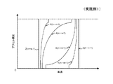
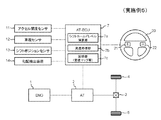
本発明の実施例1に係る自動変速機の変速制御装置について図面を用いて説明する。図1は、本発明の実施例1に係る自動変速機の変速制御装置を含む車両の構成を模式的に示したブロック図である。図2は、本発明の実施例1に係る自動変速機の変速制御装置で演算されるシフトホールドレベルの変化を説明するためのタイムチャートである。図3は、本発明の実施例1に係る自動変速機の変速制御装置において用いられる変速線のイメージ図である。
A shift control apparatus for an automatic transmission according to
図1を参照すると、自動変速機の変速制御装置を含む車両は、エンジン1と駆動輪4、5との間の動力伝達経路に自動変速機2及びデファレンシャルギヤ3が設けられている。車両は、エンジン1と、自動変速機2と、デファレンシャルギヤ3と、駆動輪4、5と、電子制御装置7と、アクセル開度センサ11と、車速センサ12と、シフトポジションセンサ13と、ステアリング20と、を有する。なお、図1では、エンジン1のみを動力源とする車両を示しているが、エンジンとモータを動力源とするハイブリッド車両や、モータのみを動力源とする電気自動車に適用してもよい。
Referring to FIG. 1, a vehicle including a shift control device for an automatic transmission is provided with an
エンジン1は、シリンダー内で燃料を爆発燃焼させ、その熱エネルギによって回転動力を出力する内燃機関であり、燃料の噴出量を調整するインジェクタアクチュエータ(図示せず)、燃料の点火時期を調整するイグナイタアクチュエータ(図示せず)等を有する。エンジン1の回転動力は、クランクシャフトを介して自動変速機2に伝達される。エンジン1は、エンジン制御装置(図示せず)に通信可能に接続されており、エンジン制御装置によって制御される。
The
自動変速機2は、エンジン1から出力された回転動力を変速してデファレンシャルギヤ3を介して駆動輪4、5に伝達する機構である。自動変速機2は、例えば、エンジン1から出力された回転動力が、トルクコンバータ(図示せず)を介して遊星歯車機構(複数の遊星歯車機構が組み合わさったもの)に入力され、当該遊星歯車機構で変速されてデファレンシャルギヤ3に出力される。自動変速機2は、遊星歯車機構における所定の回転要素間を断接可能に係合させるクラッチや、所定の回転要素の回転を止めるブレーキを有し、当該クラッチや当該ブレーキを油圧操作する油圧回路を有し、当該油圧回路において油路の切替や油圧調整するソレノイドを有する。自動変速機2は、電子制御装置7に通信可能に接続されており、電子制御装置7によって制御される。
The
電子制御装置7は、自動変速機2の動作を制御するコンピュータである。電子制御装置7は、変速制御装置となる。電子制御装置7は、自動変速機2における各種アクチュエータ(図示せず;例えば、ソレノイド)、各種センサ11〜13、スイッチ21、22等と通信可能に接続されている。電子制御装置7は、各種センサ11〜13、スイッチ21、22等からの信号に応じて、所定のプログラム(データベース、マップ等を含む)に基づいて制御処理を行う。電子制御装置7は、プログラムを実行することで、シフトホールドレベル演算部7aと、変速処理部7bと、記憶部7cと、が実現される。
The electronic control device 7 is a computer that controls the operation of the
シフトホールドレベル演算部7aは、シフトホールドレベルを演算する機能部である。シフトホールドレベル演算部7aは、各種センサ11〜13、スイッチ21、22等の信号による車両の状態(例えば、車速等)や運転者の操作(例えば、アクセル等)に基づいてシフトホールドレベルを演算する。シフトホールドレベル演算部7aは、通常の自動変速状態(自動変速モード)に戻して良い状況(例えば、車速、アクセル開度とも一定な状態が継続しているような状況)では0%に向かって減少するように演算し、一方、シフトをホールド(手動変速モードに)した方が良い状況(例えば、ワインディングロード走行中のようなアクセルが常に変化している場合)では100%に向かって増加するように演算する。シフトホールドレベル演算部7aは、アップシフトスイッチ21又はダウンシフトスイッチ22でのON操作(シフトレバーによるアップシフト又はダウンシフトの操作でも可)に応じて変速処理部7bにより自動変速機2の変速が行われた場合、シフトホールドレベルを強制的に100%にする。シフトホールドレベル演算部7aは、シフトホールドレベルが0%のときに、アップシフトスイッチ21又はダウンシフトスイッチ22での操作(シフトレバーによるアップシフト又はダウンシフトの操作でも可)が行われていない場合は、運転者が手動操作する意思がないといえるので、自動変速モードを維持するべく、シフトホールドレベルを0%のままに固定する。シフトホールドレベル演算部7aで演算されたシフトホールドレベルは、変速処理部7bにおいて変速処理する際に用いられる。
The shift hold
ここで、シフトホールドレベルとは、完全にシフト(変速段)をホールドする状態(手動変速状態)を100%とし、通常の自動変速状態を0%とし、車両の状態や運転者の操作によって0%〜100%の間で増減するレベルである。シフトホールドレベルは、手動変速モードと自動変速モードとの間を選択的に切り替えるための指標ではなく、手動変速モードの度合いと自動変速モードの度合いとを参照するためのものである。 Here, the shift hold level is defined as 100% when the shift (shift stage) is completely held (manual shift state), 0% when the normal automatic shift state is set, and 0 depending on the state of the vehicle or the driver's operation. It is a level which increases or decreases between% and 100%. The shift hold level is not an index for selectively switching between the manual transmission mode and the automatic transmission mode, but is for referring to the degree of the manual transmission mode and the degree of the automatic transmission mode.
シフトホールドレベルの演算処理の例を示す。 An example of shift hold level calculation processing is shown.
シフトホールドレベル演算部7aは、[1]アクセルペダルを踏み込んでいる状態(実アクセル開度が予め設定された閾値以上の状態;アクセルONの状態)では、シフトホールドレベルが0%より大きいときに、下記の演算式[数式1]を用いて、シフトホールドレベルを0%(通常の自動変速)側の方向に変更するように演算する(図2のT2−T3間、T4−T5間参照)。ここで、L1は今回のシフトホールドレベルであり、L0は前回のシフトホールドレベルであり、K1は任意の正の定数[%/sec]である。アクセルペダルを踏み込んでいる状態が継続している場合、運転者が自動変速を望んでいると考えられるので、今回のシフトホールドレベルL1をシフトホールドレベル0%(通常の自動変速)側に変更する。なお、今回のシフトホールドレベルL1は、[数式1]により0%以下となる場合、0%とする(図2のT5以降参照)。
When the shift hold level is greater than 0% when the accelerator pedal is depressed (the actual accelerator opening is equal to or greater than a preset threshold; the accelerator is on) [1] Using the following calculation formula [Formula 1], the shift hold level is calculated to be changed to the direction of 0% (normal automatic shift) (see between T2 and T3 and between T4 and T5 in FIG. 2). . Here, L 1 is the current shift hold level, L 0 is the previous shift hold level, and K 1 is an arbitrary positive constant [% / sec]. If the state of depressing the accelerator pedal is continued, because the driver is considered wants automatic transmission, changing the current shift
[数式1]
L1=L0−K1
※L1:今回のシフトホールドレベル
L0:前回のシフトホールドレベル
K1:任意の正の定数[%/sec]
[Formula 1]
L 1 = L 0 −K 1
* L 1 : Current shift hold level L 0 : Previous shift hold level K 1 : Arbitrary positive constant [% / sec]
シフトホールドレベル演算部7aは、[2]アクセルペダルを戻している状態(実アクセル開度が予め設定された閾値未満の状態;アクセルOFFの状態)では、シフトホールドレベルが0%より大きく100%より小さいときに、下記の演算式[数式2]を用いて、シフトホールドレベルを100%(シフトホールド)側の方向に変更するように演算する(図2のT3−T4間参照)。ここで、L1は今回のシフトホールドレベルであり、L0は前回のシフトホールドレベルであり、K2は任意の正の定数[%/sec]である。アクセルペダルを戻している状態が継続している場合、運転者がマニュアル変速を望んでいると考えられるので、今回のシフトホールドレベルL1をシフトホールドレベル100%(シフトホールド)側に変更する。なお、今回のシフトホールドレベルL1は、[数式2]により100%以上となる場合、100%とする(図2のT1−T2間参照)。また、アクセルペダルを戻している状態であってもシフトホールドレベルが0%である場合、アップシフトスイッチ21又はダウンシフトスイッチ22の操作がない限りシフトホールドレベルの更新が行われないので、シフトホールドレベルは0%に固定される(図2のT1以前、及び、T6以降参照)。
The shift hold
[数式2]
L1=L0+K2
※L1:今回のシフトホールドレベル
L0:前回のシフトホールドレベル
K2:任意の正の定数[%/sec]
[Formula 2]
L 1 = L 0 + K 2
* L 1 : Current shift hold level L 0 : Previous shift hold level K 2 : Arbitrary positive constant [% / sec]
変速処理部7bは、自動変速機2を変速制御処理する機能部である。変速処理部7bは、アップシフトスイッチ21でON操作(シフトレバーによるアップシフトの操作でも可)されると自動変速機2のシフト段を1段上げるように制御する。なお、変速処理部7bは、シフトレバーが操作されたときは、シフトポジションセンサ13からの信号に基づいて変速制御する。変速処理部7bは、ダウンシフトスイッチ22でON操作(シフトレバーによるダウンシフトの操作でも可)されると自動変速機2のシフト段を1段下げるように制御する。変速処理部7bは、アップシフトスイッチ21又はダウンシフトスイッチ22でON操作されたときに、変速線処理を行う。変速処理部7bは、アップシフトスイッチ21及びダウンシフトスイッチ22で操作されていないときに、シフトホールドレベル演算部7aで演算されたリアルタイムのシフトホールドレベルを取得し、0%より大きい場合には、取得したシフトホールドレベルに更新して、変速線処理を行う。変速処理部7bは、変速線処理において、記憶部7cに記憶された変速マップ(図3参照)から、取得したシフトホールドレベルに基づいて対応する変速線を選択して、選択された変速線に基づいてアクセル開度及び車速に応じて自動変速機2を変速制御処理する。
The shift processing unit 7b is a functional unit that performs shift control processing on the
シフトホールドレベルに応じて対応する変速線を選択する例として、変速処理部7bは、例えば、[1]シフトホールドレベルが0〜19%のとき、変速マップにおける変速線A(自動変速用の変速線;A(n→n+1)、A(n→n−1))を選択し、[2]シフトホールドレベルが20〜69%のとき、変速マップにおける変速線N(変速線Aと変速線Zの中間;N(n→n+1)、N(n→n−1))を選択し、[3]シフトホールドレベルが70〜100%のとき、変速マップにおける変速線Z(シフトホールド用の変速線;Z(n→n+1)、Z(n→n−1))を選択する(図3参照、nは変速段)。なお、シフトホールド用の変速線Z(Z(n→n+1)、Z(n→n−1))は、アクセル開度にかかわらず所定の車速で変速(シフトアップ、シフトダウン)を行う変速線となる。また、自動変速用の変速線A(n→n+1)は、アクセル開度が高くなるにしたがい高い車速でシフトアップを行う変速線となり、変速線A(n→n−1)は、アクセル開度が高くなるにしたがい高い車速でシフトダウンを行う変速線となる。また、シフトアップ側では、変速線A(n→n+1)、変速線N(n→n+1)、変速線Z(n→n+1)の順に、変速を行う車速が高くなり、シフトダウン側では、変速線A(n→n−1)、変速線N(n→n−1)、変速線Z(n→n−1)の順に、変速を行う車速が低くなる。図3は、3つの変速線(シフトアップ及びシフトダウンで計6つの変速線)を用いた例であるが、2つ以上(シフトアップ及びシフトダウンで計4つ以上の変速線)の変速線であれば幾つでもよい。 As an example of selecting the corresponding shift line according to the shift hold level, the shift processing unit 7b, for example, [1] When the shift hold level is 0 to 19%, the shift line A (shift for automatic shift) Line; A (n → n + 1), A (n → n−1)) and [2] When the shift hold level is 20 to 69%, the shift line N (shift line A and shift line Z in the shift map) N (n → n + 1), N (n → n−1)) and [3] When the shift hold level is 70 to 100%, the shift line Z (shift line for shift hold) in the shift map Z (n → n + 1), Z (n → n−1)) is selected (see FIG. 3, n is a gear). Note that the shift-hold shift line Z (Z (n → n + 1), Z (n → n−1)) is a shift line that shifts (shifts up and down) at a predetermined vehicle speed regardless of the accelerator opening. It becomes. The shift line A (n → n + 1) for automatic shift is a shift line that shifts up at a higher vehicle speed as the accelerator opening increases, and the shift line A (n → n−1) is the accelerator opening. As the speed increases, the shift line changes down at a higher vehicle speed. On the upshift side, the vehicle speed at which the shift is performed increases in the order of the shift line A (n → n + 1), the shift line N (n → n + 1), and the shift line Z (n → n + 1). The vehicle speed at which the gear shift is performed decreases in the order of line A (n → n−1), shift line N (n → n−1), and shift line Z (n → n−1). FIG. 3 shows an example using three shift lines (a total of six shift lines for shift up and down), but two or more shift lines (a total of four or more shift lines for shift up and shift down). Any number is acceptable.
選択された変速線に基づいてアクセル開度及び車速に応じて自動変速機2を変速制御処理する例として、変速処理部7bは、例えば、変速線N(N(n→n+1)、N(n→n−1))を選択した場合、実アクセル開度(アクセル開度センサ11で検出されたアクセル開度)における実車速(車速センサ12で検出された車速)が、[1]選択されたシフトアップ側の変速線N(n→n+1)の実アクセル開度に対応する車速以上となったときにシフトアップする変速処理を行い、[2]選択されたシフトダウン側の変速線N(n→n−1)の実アクセル開度に対応する車速以下となったときにシフトダウンする変速処理を行い、[3]変速線間(例えば、N(n→n+1)とN(n→n−1)との間)の車速であるときに現状の変速段を維持する。変速線A、変速線Zについても同様である。
As an example of performing a shift control process on the
記憶部7cは、変速マップ、プログラム等の所定の情報を記憶する機能部である。記憶部7cは、変速処理部7bの要求に応じて、要求に対応する情報を変速処理部7bに提供する。 The storage unit 7c is a functional unit that stores predetermined information such as a shift map and a program. The storage unit 7c provides information corresponding to the request to the shift processing unit 7b in response to the request of the shift processing unit 7b.
アクセル開度センサ11は、アクセルペダル(図示せず;アクセルレバーでも可)の操作量に対応するアクセル開度を検出するセンサである。車速センサ12は、車両の速度を検出するセンサである。シフトポジションセンサ13は、シフトレバーの操作位置(パーキングP、ニュートラルN、ドライブD、シフトアップ+、シフトダウン−等)を検出するセンサである。各種センサ11、12、13は、電子制御装置7と通信可能に接続されている。
The accelerator opening sensor 11 is a sensor that detects an accelerator opening corresponding to an operation amount of an accelerator pedal (not shown; an accelerator lever may be used). The
ステアリング20は、車両の進行方向を任意に変えるための舵取り装置であり、図1ではハンドルである。ステアリング20には、手動変速を行うためのアップシフトスイッチ21及びダウンシフトスイッチ22が取り付けられている。アップシフトスイッチ21は、自動変速機2の変速段を手動操作でシフトアップするためのスイッチ(+パドルともいう)である。ダウンシフトスイッチ22は、自動変速機2の変速段を手動操作でシフトダウンするためのスイッチ(−パドルともいう)である。各スイッチ21、22は、電子制御装置7と通信可能に接続されている。
The steering 20 is a steering device for arbitrarily changing the traveling direction of the vehicle, and is a handle in FIG. An
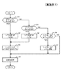
次に、本発明の実施例1に係る自動変速機の変速制御装置の動作について図面を用いて説明する。図4は、本発明の実施例1に係る自動変速機の変速制御装置の動作を模式的に示したフローチャート図である。なお、自動変速機の変速制御装置を含む車両の構成部については、図1を参照されたい。 Next, the operation of the shift control apparatus for an automatic transmission according to the first embodiment of the present invention will be described with reference to the drawings. FIG. 4 is a flowchart schematically showing the operation of the shift control device for the automatic transmission according to the first embodiment of the present invention. Refer to FIG. 1 for the components of the vehicle including the shift control device for the automatic transmission.
まず、電子制御装置7は、ダウンシフトスイッチ22がONになったか否かを判断する(ステップA1)。ダウンシフトスイッチ22がONになっていない場合(ステップA1のNO)、ステップA3に進む。
First, the electronic control unit 7 determines whether or not the
ダウンシフトスイッチ22がONになった場合(ステップA1のYES)、電子制御装置7は、自動変速機2のシフト段(変速段)を1段下げるように制御する(ステップA2)。ステップA2の後、ステップA5に進む。
When the
ダウンシフトスイッチ22がONになっていない場合(ステップA1のNO)、電子制御装置7は、アップシフトスイッチ21がONになったか否かを判断する(ステップA3)。アップシフトスイッチ21がONになっていない場合(ステップA3のNO)、ステップA6に進む。
When the
アップシフトスイッチ21がONになった場合(ステップA3のYES)、電子制御装置7は、自動変速機2のシフト段(変速段)を1段上げるように制御する(ステップA4)。ステップA4の後、ステップA5に進む。
When the
ステップA2又はステップA4の後、電子制御装置7は、シフトホールドレベル演算部7aでのシフトホールドレベルを強制的に100%にする(ステップA5)。なお、ステップA5は、図2のT1の時点に相当する。ステップA5の後、ステップA8に進む。
After step A2 or step A4, the electronic control unit 7 forcibly sets the shift hold level in the shift hold
アップシフトスイッチ21がONになっていない場合(ステップA3のNO)、電子制御装置7は、シフトホールドレベル演算部7aでのシフトホールドレベル(演算された最新のシフトホールドレベル)が0%より大きいか否かを判断する(ステップA6)。シフトホールドレベル演算部7aでのシフトホールドレベルが0%以下である場合(ステップA6のNO)、シフトホールドレベルが0%であるので、シフトホールドレベルを更新することなく、ステップA8に進む。なお、ステップA6のNOは、図2のT1より前、及び、T5より後の時点に相当する。
When the
シフトホールドレベル演算部7aでのシフトホールドレベルが0%より大きい場合(ステップA6のYES)、電子制御装置7は、シフトホールドレベル演算部7aでのシフトホールドレベルの値を更新(連続的又は断続的に更新処理)する(ステップA7)。ステップA7の後、ステップA8に進む。なお、ステップA7は、図2のT1〜T5の間の時点に相当する。
If the shift hold level in the shift hold
ステップA5の後、ステップA7の後、又は、ステップA6のNOの場合、電子制御装置7は、シフトホールドレベル演算部7aでの最新のシフトホールドレベル(ステップA5の後の場合は100%、ステップA7の後の場合は更新後の最新の値、ステップA6のNOの場合は0%)に応じて、変速処理部7bにて変速線(例えば、図3参照)を選択し、選択された変速線に基づいて実アクセル開度(アクセル開度センサ11によって検出された値)及び実車速(車速センサ12によって検出された値)に応じて自動変速機2を変速制御処理(シフトダウン、シフトアップ、変速段維持の制御処理)する(ステップA8)。ステップA8の後、スタートに戻る。
After step A5, after step A7, or in the case of NO at step A6, the electronic control unit 7 determines that the latest shift hold level in the shift hold
実施例1によれば、自動的に演算設定されるシフトホールドレベルによって変速モードの切り替えが自動的に行われるため、モード変更に伴う煩わしい操作が不要となり、操作性、燃費を向上させることができる。また、自動的に演算設定されるシフトホールドレベルによって変速モードの切り替えが多段的に行われるため、車両状態の急変(シフト段の急変)がなく、ドライバビリティ、フィーリングを向上させることができる。また、アップシフトスイッチ21及びダウンシフトスイッチ22の操作による手動変速制御を新設せずに自動変速制御の改造のみで変速が実現できるので、制御の簡素化を図ることができる。さらに、アップシフトスイッチ21及びダウンシフトスイッチ22の操作により、シフトをホールドすることができるので、操作性、利便性を向上させることができる。
According to the first embodiment, since the shift mode is automatically switched by the shift hold level that is automatically calculated and set, troublesome operations associated with the mode change are unnecessary, and operability and fuel consumption can be improved. . Further, since the shift mode is switched in multiple stages according to the shift hold level that is automatically calculated and set, there is no sudden change of the vehicle state (abrupt change of the shift stage), and drivability and feeling can be improved. Further, since manual shift control by operating the
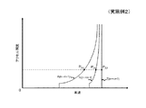
本発明の実施例2に係る自動変速機の変速制御装置について図面を用いて説明する。図5は、本発明の実施例2に係る自動変速機の変速制御装置において演算される変速点を説明するためのイメージ図である。
A shift control apparatus for an automatic transmission according to
実施例2は、電子制御装置(図1の7に相当)の変速処理部(図1の7bに相当)において、実施例1のようにシフトホールドレベルに応じて予め設定された変速線(図3参照)を選択し、選択された変速線に基づいてアクセル開度及び車速に応じて変速制御処理するのではなく、シフトホールドレベル及びアクセル開度に応じて予め設定された変速マップにおける変速線に基づいて変速点を「演算」し、演算された変速点に基づいて車速に応じて変速制御処理するようにしたものである。その他の構成は、実施例1と同様である。 In the second embodiment, the shift processing unit (corresponding to 7b in FIG. 1) of the electronic control unit (corresponding to 7 in FIG. 1) is set in advance according to the shift hold level as in the first embodiment (see FIG. 1). 3), and shift control processing is not performed in accordance with the accelerator opening and the vehicle speed based on the selected shift line, but in the shift map set in advance according to the shift hold level and the accelerator opening. The shift point is "calculated" based on the above, and the shift control process is performed according to the vehicle speed based on the calculated shift point. Other configurations are the same as those of the first embodiment.
シフトホールドレベルに応じて変速点を演算する例として、例えば、記憶部(図1の7cに相当)において、図3と同様に、[1]シフトホールドレベルが0%のときの変速線A(自動変速用の変速線;A(n→n+1)、A(n→n−1))、[2]シフトホールドレベルが40%のときの変速線N(変速線Aと変速線Zの中間;N(n→n+1)、N(n→n−1))、[3]シフトホールドレベルが100%のときの変速線Z(シフトホールド用の変速線;Z(n→n+1)、Z(n→n−1))を記憶している場合、変速処理部(図1の7bに相当)は、以下のようにして変速点を演算する。 As an example of calculating the shift point according to the shift hold level, for example, in the storage unit (corresponding to 7c in FIG. 1), as in FIG. 3, [1] Shift line A (when the shift hold level is 0% ( Shift line for automatic shift; A (n → n + 1), A (n → n−1)), [2] Shift line N when shift hold level is 40% (intermediate between shift line A and shift line Z; N (n → n + 1), N (n → n−1)), [3] Shift line Z when shift hold level is 100% (shift line for shift hold; Z (n → n + 1), Z (n → n-1)) is stored, the shift processing unit (corresponding to 7b in FIG. 1) calculates the shift point as follows.
シフトホールドレベルが0%の場合、実アクセル開度(図1のアクセル開度センサ11で検出された値)に対応する変速線A(A(n→n+1)、A(n→n−1))上のシフトダウン側の変速点PAD、及びシフトアップ側の変速点PAUを求める。 When the shift hold level is 0%, shift lines A (A (n → n + 1), A (n → n−1) corresponding to the actual accelerator opening (value detected by the accelerator opening sensor 11 in FIG. 1). ) The upper shift point P AD and the upper shift point P AU are obtained.
シフトホールドレベルが0%より大きく40%より小さい場合、変速線A(A(n→n+1)、A(n→n−1))及び変速線N(N(n→n+1)、N(n→n−1))に基づいて、実アクセル開度(図1のアクセル開度センサで検出された値)に対応する変速線A(A(n→n+1)、A(n→n−1))上のシフトアップ側の変速点PAU、及びシフトダウン側の変速点PAD、並びに、実アクセル開度に対応する変速線N(N(n→n+1)、N(n→n−1))上のシフトアップ側の変速点PNU、及びシフトダウン側の変速点PNDを求め、各変速点及びシフトホールドレベルの値を以下の演算式[数式3]を用いて演算することで、シフトホールドレベルL及び実アクセル開度に対応するシフトアップ側の変速点PLU、及びシフトダウン側の変速点PLDを求める。 When the shift hold level is greater than 0% and less than 40%, the shift line A (A (n → n + 1), A (n → n−1)) and the shift lines N (N (n → n + 1), N (n → n) n-1)), the shift line A (A (n → n + 1), A (n → n-1)) corresponding to the actual accelerator opening (the value detected by the accelerator opening sensor in FIG. 1). Upper shift point P AU on the upper shift side, shift point P AD on the lower shift side, and shift lines N (N (n → n + 1), N (n → n−1)) corresponding to the actual accelerator opening. The shift point P NU on the upshift side and the shift point P ND on the shift down side are obtained, and the shift points and the shift hold level values are calculated using the following arithmetic expression [Formula 3]. shift point P LU upshift side corresponding to the hold level L and the actual accelerator pedal position And downshift side obtains the shift point P LD.
[数式3]
PLU={(40−L)×PAU+(L−0)×PNU}/40
PLD={(40−L)×PAD+(L−0)×PND}/40
※PLU:演算されるシフトアップ側の変速点
PLD:演算されるシフトダウン側の変速点
L:シフトホールドレベル
PAU:変速線A上のシフトアップ側の変速点
PAD:変速線A上のシフトダウン側の変速点
PNU:変速線N上のシフトアップ側の変速点
PND:変速線N上のシフトダウン側の変速点
[Formula 3]
P LU = {(40−L) × P AU + (L−0) × P NU } / 40
P LD = {(40−L) × P AD + (L−0) × P ND } / 40
* P LU : Shift-up shift point to be calculated P LD : Shift-shift shift point to be calculated L: Shift hold level P AU : Shift-up shift point on shift line A P AD : Shift line A Upshift down shift point P NU : Shift up shift point on shift line N P ND : Shift down shift point on shift line N
シフトホールドレベルが40%の場合、実アクセル開度(図1のアクセル開度センサで検出された値)に対応する変速線N(N(n→n+1)、N(n→n−1))上のシフトダウン側の変速点PND、及びシフトアップ側の変速点PNUを求める。 When the shift hold level is 40%, the shift line N (N (n → n + 1), N (n → n−1)) corresponding to the actual accelerator opening (value detected by the accelerator opening sensor in FIG. 1). An upper shift point P ND on the downshift side and a shift point P NU on the upshift side are obtained.
シフトホールドレベルが40%より大きく100%より小さい場合、変速線N(N(n→n+1)、N(n→n−1))及び変速線Z(Z(n→n+1)、Z(n→n−1))に基づいて、実アクセル開度に対応する変速線N(N(n→n+1)、N(n→n−1))上のシフトアップ側の変速点PNU、及びシフトダウン側の変速点PND、並びに、実アクセル開度(図1のアクセル開度センサで検出された値)に対応する変速線Z(Z(n→n+1)、Z(n→n−1))上のシフトアップ側の変速点PZU、及びシフトダウン側の変速点PZDを求め、各変速点及びシフトホールドレベルの値を以下の演算式[数式4]を用いて演算することで、シフトホールドレベルL及び実アクセル開度に対応するシフトアップ側の変速点PLU、及びシフトダウン側の変速点PLDを求める。 When the shift hold level is larger than 40% and smaller than 100%, the shift line N (N (n → n + 1), N (n → n−1)) and the shift line Z (Z (n → n + 1), Z (n → n-1)), the shift point P NU on the upshift side on the shift line N (N (n → n + 1), N (n → n-1)) corresponding to the actual accelerator opening, and the shift down Side shift point P ND and the shift line Z (Z (n → n + 1), Z (n → n−1)) corresponding to the actual accelerator opening (value detected by the accelerator opening sensor in FIG. 1) The shift point P ZU on the upshift side and the shift point P ZD on the shift down side are obtained, and the shift point and the shift hold level are calculated using the following equation [Formula 4], thereby shifting. shift point of the shift-up side P corresponding to the hold level L and the actual accelerator pedal position U, and the shift-down side obtains the shift point P LD.
[数式4]
PLU={(100−L)×PNU+(L−40)×PZU}/(100−40)
PLD={(100−L)×PND+(L−40)×PZD}/(100−40)
※PLU:演算されるシフトアップ側の変速点
PLD:演算されるシフトダウン側の変速点
L:シフトホールドレベル
PNU:変速線N上のシフトアップ側の変速点
PND:変速線N上のシフトダウン側の変速点
PZU:変速線Z上のシフトアップ側の変速点
PZD:変速線Z上のシフトダウン側の変速点
[Formula 4]
P LU = {(100−L) × P NU + (L−40) × P ZU } / (100−40)
P LD = {(100−L) × P ND + (L−40) × P ZD } / (100−40)
* P LU : Shift-up shift point calculated P LD : Shift-down shift point calculated L: Shift hold level P NU : Shift-up shift point on shift line N P ND : Shift line N Upper shift-down shift point P ZU : Shift-up shift point on shift line Z P ZD : Shift-down shift point on shift line Z
例えば、シフトホールドレベルL=70%の場合、シフトホールドレベルL及び実アクセル開度に対応するシフトアップ側の変速点PLUは、以下の演算式[数式5]を用いて求める(図5参照)。 For example, when the shift hold level L = 70%, the shift-up side shift point P LU corresponding to the shift hold level L and the actual accelerator opening is obtained using the following arithmetic expression [Formula 5] (see FIG. 5). ).
[数式5]
PLU={(100−70)×PNU+(70−40)×PZU}/(100−40)
[Formula 5]
P LU = {(100−70) × P NU + (70−40) × P ZU } / (100−40)
シフトホールドレベルが100%の場合、実アクセル開度(図1のアクセル開度センサで検出された値)に対応する変速線Z(Z(n→n+1)、Z(n→n−1))上のシフトダウン側の変速点PZD、及びシフトアップ側の変速点PZUを求める。 When the shift hold level is 100%, the shift line Z (Z (n → n + 1), Z (n → n−1)) corresponding to the actual accelerator opening (value detected by the accelerator opening sensor in FIG. 1). The upper shift point P ZD and the upper shift point P ZU are obtained.
なお、ここでは、3つの変速線(シフトアップ及びシフトダウンで計6つの変速線)を用いた例であるが、2つ以上(シフトアップ及びシフトダウンで計4つ以上の変速線)の変速線であれば幾つでもよい。 In this example, three shift lines (a total of six shift lines for shift up and shift down) are used, but two or more shift lines (a total of four or more shift lines for shift up and shift down) are used. Any number of lines is acceptable.
演算された変速点に基づいて変速制御処理する例として、変速処理部(図1の7b)は、例えば、シフトアップ側の変速点PLU、及びシフトダウン側の変速点PLDを求めた後、実車速(車速センサ12で検出された車速)が、[1]シフトアップ側の変速点PLUに対応する車速以上となったときにシフトアップする変速処理を行い、[2]シフトダウン側の変速点PLDに対応する車速以下となったときにシフトダウンする変速処理を行い、[3]変速点PLU、PLD間の車速であるときに現状の変速段を維持する。 As an example of performing the shift control process based on the calculated shift point, the shift processing unit (7b in FIG. 1) obtains, for example, the shift point P LU on the upshift side and the shift point P LD on the shift down side. When the actual vehicle speed (the vehicle speed detected by the vehicle speed sensor 12) is equal to or higher than the vehicle speed corresponding to the shift point PLU on the upshift side, [2] the downshift side A shift process is performed to shift down when the vehicle speed is equal to or less than the vehicle speed corresponding to the shift point PLD . [3] The current gear position is maintained when the vehicle speed is between the shift points PLU and PLD .
実施例2によれば、実施例1と同様に、自動的に演算設定されるシフトホールドレベルによって変速モードの切り替えが自動で行われるため、モード変更に伴う煩わしい操作が不要となり、操作性、燃費を向上させることができる。また、自動的に演算設定されるシフトホールドレベルによって変速モードの切り替えが連続的に行われるため、車両状態の急変(シフト段の急変)がなく、実施例1よりもドライバビリティ、フィーリングを向上させることができる。また、実施例1と同様に、アップシフトスイッチ(図1の21に相当)及びダウンシフトスイッチ(図1の22に相当)の操作による手動変速制御を新設せずに自動変速制御の改造のみで変速が実現できるので、制御の簡素化を図ることができる。さらに、実施例1と同様に、アップシフトスイッチ(図1の21に相当)及びダウンシフトスイッチ(図1の22に相当)の操作により、シフトをホールドすることができるので、操作性、利便性を向上させることができる。 According to the second embodiment, as in the first embodiment, since the shift mode is automatically switched according to the shift hold level that is automatically calculated and set, troublesome operations associated with the mode change are not required, and operability and fuel efficiency are reduced. Can be improved. In addition, since the shift mode is continuously switched according to the shift hold level that is automatically calculated and set, there is no sudden change of the vehicle state (abrupt change of the shift stage), and drivability and feeling are improved as compared with the first embodiment. Can be made. Similarly to the first embodiment, the manual shift control by the operation of the upshift switch (corresponding to 21 in FIG. 1) and the downshift switch (corresponding to 22 in FIG. 1) is not newly provided, and only the automatic shift control is modified. Since shifting can be realized, control can be simplified. Further, as in the first embodiment, the shift can be held by the operation of the upshift switch (corresponding to 21 in FIG. 1) and the downshift switch (corresponding to 22 in FIG. 1). Can be improved.
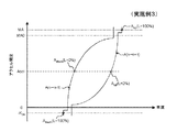
本発明の実施例3に係る自動変速機の変速制御装置について図面を用いて説明する。図6は、本発明の実施例3に係る自動変速機の変速制御装置におけるアクセル開度の補正を説明するためのイメージ図である。 A shift control apparatus for an automatic transmission according to Embodiment 3 of the present invention will be described with reference to the drawings. FIG. 6 is an image diagram for explaining correction of the accelerator opening in the shift control device for an automatic transmission according to the third embodiment of the present invention.
実施例3は、電子制御装置(図1の7に相当)の変速処理部(図1の7bに相当)において、実施例1、2のようにアクセル開度センサ(図1の11)で検出された値(実アクセル開度)をそのまま用いて変速制御処理するのではなく、シフトホールドレベルLに基づいて実アクセル開度Accl(アクセル開度センサで検出された値)を補正し、補正された補正アクセル開度Aup、Adownに応じて、予め設定された変速線A(A(n→n+1)、A(n→n−1);自動変速用の変速線を一部改良した変速線)に基づいて変速制御処理を行うようにしたものである。その他の動作、構成は、実施例1と同様である。 The third embodiment is detected by the accelerator opening sensor (11 in FIG. 1) as in the first and second embodiments in the shift processing unit (corresponding to 7b in FIG. 1) of the electronic control unit (corresponding to 7 in FIG. 1). Instead of performing the shift control process using the obtained value (actual accelerator opening) as it is, the actual accelerator opening Accl (the value detected by the accelerator opening sensor) is corrected based on the shift hold level L to be corrected. A shift line A (A (n → n + 1), A (n → n−1)) set in advance according to the corrected accelerator opening A up , A down ; The shift control process is performed on the basis of the line. Other operations and configurations are the same as those in the first embodiment.
ここで、補正アクセル開度は、シフトアップ側の変速線A(n→n+1)に対して用いる補正アクセル開度Aupと、シフトダウン側の変速線A(n→n−1)に対して用いる補正アクセル開度Aupと、があり、シフトホールドレベルLに応じて実アクセル開度Acclに基づいて演算(補正)される。 Here, the corrected accelerator opening is the corrected accelerator opening A up used for the shift-up side shift line A (n → n + 1) and the shift-down side shift line A (n → n−1). There is a correction accelerator opening A up to be used, which is calculated (corrected) based on the actual accelerator opening Accl according to the shift hold level L.
シフトアップ側の補正アクセル開度Aupは、シフトホールドレベルLに応じて実アクセル開度Accl以上の値に補正される。シフトホールドレベルL=0%のときの補正アクセル開度Aup(L=0%)を実アクセル開度Acclと一致させ、シフトホールドレベルLが大きくなるにしたがい補正アクセル開度Aupは大きくなり、シフトホールドレベルL=100%のときの補正アクセル開度Aup(L=100%)で最大となる(図6参照)。例えば、「Aup(L=100%)>Aup(L=50%)>Aup(L=10%)>Accl」のような関係になる。補正アクセル開度AupをシフトホールドレベルLが大きくなるにしたがい大きく補正するのは、シフトホールドレベルLが大きくなるにしたがい、シフトアップしにくくする(シフトホールドしやすくする)べく、変速点に対応する車速を高くするためである。補正アクセル開度Aupは、例えば、以下の演算式[数式6]を用いて演算することができる。なお、[数式6]によりAupがMA以上となる場合は、Aup=MAとする。 Correction accelerator opening A Stay up-shift-up side is corrected to the actual accelerator position Accl or more values in response to the shift-hold level L. The corrected accelerator opening A up (L = 0%) when the shift hold level L = 0% is made to coincide with the actual accelerator opening Accl, and the corrected accelerator opening A up increases as the shift hold level L increases. When the shift hold level L = 100%, the corrected accelerator opening A up (L = 100%) is maximized (see FIG. 6). For example, the relationship is “A up (L = 100%)> A up (L = 50%)> A up (L = 10%)> Accl”. Correcting the corrected accelerator opening Aup as the shift hold level L increases increases the shift point in order to make it difficult to shift up (to make shift hold easier) as the shift hold level L increases. This is to increase the vehicle speed. The corrected accelerator opening A up can be calculated using, for example, the following calculation formula [Formula 6]. If A up is greater than or equal to MA according to [Equation 6], A up = MA.
[数式6]
Aup=MA−K21×(100%−K22×L)×(MA−Accl)+K23×L
※MA:Aupの最大値(=MA0+K24)
MA0:アクセル開度の最大値
K21、K22、K23、K24:任意の正の定数
[Formula 6]
A up = MA-K 21 × (100% -
* MA: Maximum value of A up (= MA0 + K 24 )
MA0: Maximum value K 21 of the accelerator opening degree, K 22, K 23, K 24: Any positive constant
シフトダウン側の補正アクセル開度Adownは、シフトホールドレベルLに応じて実アクセル開度Accl以下の値に補正される。シフトホールドレベルL=0%のときの補正アクセル開度Adown(L=0%)を実アクセル開度Acclと一致させ、シフトホールドレベルLが大きくなるにしたがい補正アクセル開度Adownは小さくなり、シフトホールドレベルL=100%のときの補正アクセル開度Adown(L=100%)で最小となる(図6参照)。例えば、「Adown(L=100%)<Adown(L=50%)<Adown(L=10%)<Accl」のような関係になる。補正アクセル開度AdownをシフトホールドレベルLが大きくなるにしたがい小さく補正するのは、シフトホールドレベルLが大きくなるにしたがい、シフトダウンしにくくする(シフトホールドしやすくする)べく、変速点に対応する車速を低くするためである。補正アクセル開度Adownは、例えば、以下の演算式[数式7]を用いて演算することができる。なお、[数式7]によりAupが−K14以下となる場合は、Adown=−K14とする。K14は任意の正の定数である。 The corrected accelerator opening A down on the downshift side is corrected to a value less than or equal to the actual accelerator opening Accl according to the shift hold level L. The corrected accelerator opening A down (L = 0%) when the shift hold level L = 0% is matched with the actual accelerator opening Accl, and the corrected accelerator opening A down decreases as the shift hold level L increases. When the shift hold level L = 100%, the corrected accelerator opening A down (L = 100%) is minimized (see FIG. 6). For example, the relationship is “A down (L = 100%) <A down (L = 50%) <A down (L = 10%) <Accl”. The corrected accelerator opening A down is corrected to be smaller as the shift hold level L becomes larger. In order to make it difficult to shift down (to make shift hold easier) as the shift hold level L becomes larger, it corresponds to the shift point. This is to reduce the vehicle speed. The corrected accelerator opening A down can be calculated using, for example, the following calculation formula [Formula 7]. In addition, when A up is equal to or lower than −K 14 according to [Equation 7], A down = −K 14 is set. K 14 is an arbitrary positive constant.
[数式7]
Adown=K11×(100%−K12×L)×Accl−K13×L
※Adown:シフトダウン側の補正アクセル開度
K11、K12、K13:任意の正の定数
L:シフトホールドレベル
Accl:実アクセル開度
[Formula 7]
A down = K 11 × (100% −K 12 × L) × Accl−K 13 × L
* A down : Corrected accelerator opening on the downshift side K 11 , K 12 , K 13 : Arbitrary positive constant L: Shift hold level Accl: Actual accelerator opening
変速線A(A(n→n+1)、A(n→n−1))は、アクセル開度が0〜MA0(アクセル開度の最大値)において自動変速用の変速線を基本とし、シフトアップ側の変速線A(n→n+1)に関してはアクセル開度がMA0〜MAの間でシフトアップ側のシフトホールド用の変速線とし、シフトダウン側の変速線A(n→n−1)に関してはアクセル開度が0〜−K14の間でシフトダウン側のシフトホールド用の変速線とする(図6参照)。 Shift line A (A (n → n + 1), A (n → n-1)) is based on the shift line for automatic shift when the accelerator opening is 0 to MA0 (maximum value of accelerator opening). For the shift line A (n → n + 1) on the side, the shift-hold shift line for the upshift side is used when the accelerator opening is between MA0 and MA, and for the shift line A (n → n−1) on the downshift side. accelerator opening degree and the transmission line for the shift hold downshift side between 0 to-K 14 (see FIG. 6).
補正された補正アクセル開度Aup、Adownに基づいて変速制御処理する例として、変速処理部(図1の7b)は、例えば、補正アクセル開度Aup、Adownを求めた後、予め設定された変速線A(A(n→n+1)、A(n→n−1);自動変速用の変速線を一部改良した変速線)に基づいて、実車速(車速センサ12で検出された車速)が、[1]シフトアップ側の補正アクセル開度Aupに対応する車速以上となったときにシフトアップする変速処理を行い、[2]シフトダウン側の補正アクセル開度Adownに対応する車速以下となったときにシフトダウンする変速処理を行い、[3]補正アクセル開度Aupに対応する車速と、補正アクセル開度Adownに対応する車速との間の車速であるときに現状の変速段を維持する。 As an example of performing the shift control process based on the corrected corrected accelerator opening Aup , Adown , the shift processing unit (7b in FIG. 1), for example, after calculating the corrected accelerator opening Aup , Adown , Based on the set shift line A (A (n → n + 1), A (n → n−1); a shift line obtained by partially improving the shift line for automatic shift), the actual vehicle speed (detected by the vehicle speed sensor 12). Shift speed up processing is performed when the vehicle speed is equal to or higher than the vehicle speed corresponding to [1] upshift side corrected accelerator opening Aup , and [2] downshift side corrected accelerator opening Adown is set. When the vehicle speed is between the vehicle speed corresponding to the corrected accelerator opening A up and the vehicle speed corresponding to the corrected accelerator opening A down , a shift process is performed to shift down when the vehicle speed falls below the corresponding vehicle speed. The current gear position To maintain.
実施例3によれば、自動的に設定されるシフトホールドレベルに応じて実アクセル開度が補正された補正アクセル開度によって変速モードを切り替えるような動作となるため、モード変更に伴う煩わしい操作が不要となり、操作性、燃費を向上させることができる。また、実アクセル開度はシフトホールドレベルが大きくなるにしたがい変速しにくく(シフトホールドしやすく)するように補正されるため、車両状態の急変(シフト段の急変)がなく、ドライバビリティ、フィーリングを向上させることができる。また、実施例1と同様に、アップシフトスイッチ(図1の21に相当)及びダウンシフトスイッチ(図1の22に相当)の操作による手動変速制御を新設せずに自動変速制御の改造のみで変速が実現できるので、制御の簡素化を図ることができる。さらに、実施例1と同様に、アップシフトスイッチ(図1の21に相当)及びダウンシフトスイッチ(図1の22に相当)の操作により、シフトをホールドすることができるので、操作性、利便性を向上させることができる。 According to the third embodiment, since the shift mode is switched according to the corrected accelerator opening in which the actual accelerator opening is corrected in accordance with the shift hold level that is automatically set, troublesome operations associated with the mode change can be performed. It becomes unnecessary, and operability and fuel consumption can be improved. In addition, the actual accelerator opening is corrected to make shifting difficult (easy to shift-shift) as the shift hold level increases, so there is no sudden change in vehicle status (abrupt shift stage shift), drivability and feeling. Can be improved. Similarly to the first embodiment, the manual shift control by the operation of the upshift switch (corresponding to 21 in FIG. 1) and the downshift switch (corresponding to 22 in FIG. 1) is not newly provided, and only the automatic shift control is modified. Since shifting can be realized, control can be simplified. Further, as in the first embodiment, the shift can be held by the operation of the upshift switch (corresponding to 21 in FIG. 1) and the downshift switch (corresponding to 22 in FIG. 1). Can be improved.
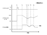
本発明の実施例4に係る自動変速機の変速制御装置について図面を用いて説明する。図7は、本発明の実施例4に係る自動変速機の変速制御装置で演算されるシフトホールドレベルの変化を説明するためのタイムチャートである。 A shift control apparatus for an automatic transmission according to Embodiment 4 of the present invention will be described with reference to the drawings. FIG. 7 is a time chart for explaining a change in the shift hold level calculated by the shift control device for an automatic transmission according to the fourth embodiment of the present invention.
実施例4は、実施例1に係る自動変速機の変速制御装置におけるシフトホールドレベル演算部(図1の7a)でのシフトホールドレベルの演算処理の変形例である。実施例4では、アクセルペダルの踏み込み量の変化がある場合(踏み込んだり戻したりしている場合)に、シフトホールドレベルを100%(シフトホールド)側の方向に補正するようにしたものである。シフトホールドレベルの演算処理以外の動作、構成は、実施例1と同様である。また、実施例4は、実施例2、3にも適用することができる。 The fourth embodiment is a modification of the shift hold level calculation process in the shift hold level calculation unit (7a in FIG. 1) in the shift control device for an automatic transmission according to the first embodiment. In the fourth embodiment, the shift hold level is corrected in the direction of 100% (shift hold) when there is a change in the amount of depression of the accelerator pedal (when the accelerator pedal is depressed or returned). Operations and configurations other than the shift hold level calculation processing are the same as those in the first embodiment. The fourth embodiment can also be applied to the second and third embodiments.
シフトホールドレベル演算部(図1の7aに相当)は、実施例1と同様に、通常の自動変速状態(自動変速モード)に戻して良い状況では0%に向かって減少するように演算し、一方、シフトをホールド(手動変速モードに)した方が良い状況では100%に向かって増加するように演算する。また、シフトホールドレベル演算部(図1の7aに相当)は、実施例1と同様に、アップシフトスイッチ(図1の21に相当)又はダウンシフトスイッチ(図1の22に相当)でのON操作(シフトレバーによるアップシフト又はダウンシフトの操作でも可)に応じて変速処理部(図1の7bに相当)により自動変速機(図1の2に相当)の変速が行われた場合、シフトホールドレベルを強制的に100%にする。シフトホールドレベル演算部(図1の7aに相当)は、実施例1と同様に、シフトホールドレベルが0%のときに、アップシフトスイッチ(図1の21に相当)又はダウンシフトスイッチ(図1の22に相当)での操作(シフトレバーによるアップシフト又はダウンシフトの操作でも可)が行われていない場合は、運転者が手動操作する意思がないといえるので、自動変速モードを維持するべく、シフトホールドレベルを0%のままに固定する。シフトホールドレベル演算部(図1の7aに相当)で演算されたシフトホールドレベルは、変速処理部(図1の7bに相当)において変速処理する際に用いられる。 The shift hold level calculation unit (corresponding to 7a in FIG. 1) calculates to decrease to 0% in a situation where it can be returned to the normal automatic shift state (automatic shift mode), as in the first embodiment. On the other hand, in a situation where it is better to hold the shift (manual shift mode), the calculation is performed so as to increase toward 100%. The shift hold level calculation unit (corresponding to 7a in FIG. 1) is turned on by an upshift switch (corresponding to 21 in FIG. 1) or a downshift switch (corresponding to 22 in FIG. 1) as in the first embodiment. When the shift of the automatic transmission (corresponding to 2 in FIG. 1) is performed by the shift processing unit (corresponding to 7b in FIG. 1) according to the operation (upshift or downshifting operation by the shift lever) is also possible. Force the hold level to 100%. Similarly to the first embodiment, the shift hold level calculation unit (corresponding to 7a in FIG. 1), when the shift hold level is 0%, upshift switch (corresponding to 21 in FIG. 1) or downshift switch (FIG. 1). When the operation (equivalent to 22) is not performed (the upshift or downshift operation by the shift lever is also possible), it can be said that the driver does not intend to perform the manual operation. The shift hold level is fixed at 0%. The shift hold level calculated by the shift hold level calculation unit (corresponding to 7a in FIG. 1) is used when the shift processing is performed in the shift processing unit (corresponding to 7b in FIG. 1).
シフトホールドレベルの演算処理の例を示す。 An example of shift hold level calculation processing is shown.
シフトホールドレベル演算部(図1の7aに相当)は、[1]実アクセル開度が予め設定された閾値以上の状態(アクセルONの状態)では、シフトホールドレベルが0%より大きく100%より小さいときに、下記の演算式[数式8]を用いて、アクセルペダルの踏み込み量(実アクセル開度)の変化量の絶対値|△Accl|に応じて、シフトホールドレベルを変更するように演算する。ここで、L1は今回のシフトホールドレベルであり、L0は前回のシフトホールドレベルであり、K11、K12[%/sec]は任意の正の定数であり、|△Accl|はアクセルペダルの踏み込み量(実アクセル開度)の変化量の絶対値である。「K11>K12|△Accl|」の場合、今回のシフトホールドレベルL1はシフトホールドレベル0%(通常の自動変速)側の方向に変更し(図7のT2−T3間、T3−T4間、T5−T6間参照)、「K11<K12|△Accl|」の場合、今回のシフトホールドレベルL1はシフトホールドレベル100%(シフトホールド)側の方向に変更し、「K11=K12|△Accl|」の場合、今回のシフトホールドレベルL1は前回のシフトホールドレベルL0と同じである。アクセルペダルの踏み込み量(実アクセル開度)の変化量の絶対値|△Accl|は、例えば、ワインディングロード走行中のようなアクセルペダルの踏み込み量が常に変化している場合では、運転者がマニュアル変速を望んでいる可能性があるので、今回のシフトホールドレベルL1をシフトホールドレベル100%(シフトホールド)側に変更するように作用する。アクセルペダルの踏み込み量が一定の状態(|△Accl|=0)は、実施例1と同様に、シフトホールドレベル0%(通常の自動変速)側の方向に変更する(図7のT2−T3間参照)。なお、今回のシフトホールドレベルL1は、[数式8]により0%以下となる場合、0%とする。
The shift hold level calculation unit (corresponding to 7a in FIG. 1) is [1] When the actual accelerator opening is equal to or greater than a preset threshold value (accelerator ON state), the shift hold level is greater than 0% and greater than 100%. When the value is small, the shift hold level is changed according to the absolute value | ΔAccl | of the change amount of the accelerator pedal depression amount (actual accelerator opening) using the following equation [Equation 8]. To do. Here, L 1 is the current shift hold level, L 0 is the previous shift hold level, K 11 and K 12 [% / sec] are arbitrary positive constants, and | ΔAccl | This is the absolute value of the amount of change in the pedal depression amount (actual accelerator opening). When “K 11 > K 12 | ΔAccl |”, the current shift hold level L 1 is changed to the
[数式8]
L1=L0−K11+K12|△Accl|
※L1:今回のシフトホールドレベル
L0:前回のシフトホールドレベル
K11、K12:任意の正の定数[%/sec]
|△Accl|:実アクセル開度の変化量の絶対値
[Formula 8]
L 1 = L 0 −K 11 + K 12 | ΔAccl |
* L 1 : Current shift hold level L 0 : Previous shift hold level K 11 , K 12 : Arbitrary positive constant [% / sec]
| △ Accl |: Absolute value of change in actual accelerator opening
シフトホールドレベル演算部(図1の7aに相当)は、[2]実アクセル開度が予め設定された閾値未満の状態(アクセルOFFの状態;アクセルペダルを戻している状態を含む)では、シフトホールドレベルが0%より大きく100%より小さいときに、下記の演算式[数式9]を用いて、シフトホールドレベルを100%(シフトホールド)側の方向に変更するように演算する(図7のT4−T5間、T6以降参照)。ここで、L1は今回のシフトホールドレベルであり、L0は前回のシフトホールドレベルであり、K21[%/sec]は任意の正の定数である。アクセルOFFの場合、運転者がマニュアル変速を望んでいると考えられるので、今回のシフトホールドレベルL1をシフトホールドレベル100%(シフトホールド)側に変更する。なお、今回のシフトホールドレベルL1は、[数式9]により100%以上となる場合、100%とする(図7のT1−T2間参照)。また、アクセルOFFの状態であってもシフトホールドレベルが0%である場合、アップシフトスイッチ(図1の21に相当)又はダウンシフトスイッチ(図1の22に相当)の操作がない限りシフトホールドレベルの更新が行われないので、シフトホールドレベルは0%に固定される(図7のT1以前参照)。 The shift hold level calculation unit (corresponding to 7a in FIG. 1) performs the shift in the state [2] where the actual accelerator opening is less than a preset threshold value (the accelerator is OFF; the accelerator pedal is returned). When the hold level is larger than 0% and smaller than 100%, the following calculation formula [Formula 9] is used to calculate the shift hold level to change in the direction of 100% (shift hold) (see FIG. 7). T4-T5, see T6 and later). Here, L 1 is the current shift hold level, L 0 is the previous shift hold level, and K 21 [% / sec] is an arbitrary positive constant. If the accelerator OFF, the driver since it is considered that wants manual shift, changes the current shift hold level L 1 in the shift-hold level of 100% (Shift Hold) side. The current shift hold level L 1 is set to 100% when it is 100% or more according to [Equation 9] (see T1-T2 in FIG. 7). If the shift hold level is 0% even when the accelerator is OFF, the shift hold is performed unless an upshift switch (corresponding to 21 in FIG. 1) or a downshift switch (corresponding to 22 in FIG. 1) is operated. Since the level is not updated, the shift hold level is fixed at 0% (refer to T1 before T1 in FIG. 7).
[数式9]
L1=L0+K21
※L1:今回のシフトホールドレベル
L0:前回のシフトホールドレベル
K21:任意の正の定数[%/sec]
[Formula 9]
L 1 = L 0 + K 21
* L 1 : Current shift hold level L 0 : Previous shift hold level K 21 : Arbitrary positive constant [% / sec]
なお、以上のようにして演算されたシフトホールドレベルは、図4のフローチャートに従って変更又は更新され、変速処理部(図1の7b)において変速制御処理する際に用いられることになる。 The shift hold level calculated as described above is changed or updated according to the flowchart of FIG. 4 and is used when the shift control processing (7b in FIG. 1) performs the shift control process.
実施例4によれば、実施例1と同様な効果を奏するとともに、アクセルONのときにアクセルペダルの踏み込み量の変化量の絶対値に応じてシフトホールドレベルを演算することで、運転者の潜在的な意図を反映した変速を実現することができる。 According to the fourth embodiment, the same effect as that of the first embodiment is obtained, and by calculating the shift hold level according to the absolute value of the change amount of the depression amount of the accelerator pedal when the accelerator is ON, the driver's latent Shift that reflects the intention of the vehicle can be realized.
本発明の実施例5に係る自動変速機の変速制御装置について図面を用いて説明する。図8は、本発明の実施例5に係る自動変速機の変速制御装置を含む車両の構成を模式的に示したブロック図である。図9は、本発明の実施例5に係る自動変速機の変速制御装置で演算されるシフトホールドレベルの変化を説明するためのタイムチャートである。 A shift control apparatus for an automatic transmission according to Embodiment 5 of the present invention will be described with reference to the drawings. FIG. 8 is a block diagram schematically illustrating the configuration of a vehicle including a shift control device for an automatic transmission according to a fifth embodiment of the present invention. FIG. 9 is a time chart for explaining a change in the shift hold level calculated by the shift control device for an automatic transmission according to the fifth embodiment of the present invention.
実施例5は、実施例1に係る自動変速機の変速制御装置におけるシフトホールドレベル演算部(図1の7a)でのシフトホールドレベルの演算処理の変形例である。実施例5は、シフトホールドレベルを、[1]平坦路を定速走行又は加速走行中でアクセルペダルの踏み込み量が一定の状態ではシフトホールドレベルが0%より大きいときに通常変速(シフトホールドレベル0%側)の方向に変更し、[2]登坂路を加速走行中、又は、降坂路を加速走行中でアクセルペダルの踏み込み量が一定の状態でもシフトホールドレベルが0%より大きいときに通常変速(シフトホールドレベル0%側)の方向に変更し、[3]その他の状態ではシフトホールドレベルが0%より大きく100%より小さいときに100%方向に変更するようにしたものである。実施例5では、路面の勾配を検出(演算でも可)する勾配検出装置(図8の14)を追加している点で、実施例1(図1参照)と異なる。シフトホールドレベルの演算処理以外の動作、構成は、実施例1と同様である。また、実施例5は、実施例2、3にも適用することができる。
The fifth embodiment is a modification of the shift hold level calculation process in the shift hold level calculation section (7a in FIG. 1) in the shift control device for an automatic transmission according to the first embodiment. In the fifth embodiment, the shift hold level is set to [1] normal shift (shift hold level) when the shift hold level is greater than 0% when the accelerator pedal is depressed at a constant speed or acceleration on a flat road. [2] Normal when the shift hold level is greater than 0% even when the accelerator pedal is depressed on the uphill road or the downhill road is accelerated. The shift is changed to the direction of shift (shift
勾配検出装置14は、車両が走行する路面の勾配を検出する装置である。勾配検出装置14には、例えば、ジャイロ効果を用いて勾配を検出するジャイロコンパスを用いることができ、エンジンの駆動力、車速、車両重量に基づいて勾配を推定(演算)する装置を用いることができる。勾配検出装置14は、電子制御装置7と通信可能に接続されている。勾配検出装置14で検出された勾配に係る情報は、電子制御装置7におけるシフトホールドレベルの演算処理において用いられる。
The
シフトホールドレベル演算部7aは、実施例1と同様に、通常の自動変速状態(自動変速モード)に戻して良い状況では0%に向かって減少するように演算し、一方、シフトをホールド(手動変速モードに)した方が良い状況では100%に向かって増加するように演算する。また、シフトホールドレベル演算部7aは、実施例1と同様に、アップシフトスイッチ21又はダウンシフトスイッチ22でのON操作(シフトレバーによるアップシフト又はダウンシフトの操作でも可)に応じて変速処理部7bにより自動変速機2の変速が行われた場合、シフトホールドレベルを強制的に100%にする。シフトホールドレベル演算部7aは、実施例1と同様に、シフトホールドレベルが0%のときに、アップシフトスイッチ21又はダウンシフトスイッチ22での操作(シフトレバーによるアップシフト又はダウンシフトの操作でも可)が行われていない場合は、運転者が手動操作する意思がないといえるので、自動変速モードを維持するべく、シフトホールドレベルを0%のままに固定する。シフトホールドレベル演算部7aで演算されたシフトホールドレベルは、変速処理部7bにおいて変速処理する際に用いられる。
Similarly to the first embodiment, the shift hold
シフトホールドレベルの演算処理の例を示す。 An example of shift hold level calculation processing is shown.
シフトホールドレベル演算部7aは、シフトホールドレベルを演算する際、車速センサ12で検出された車速に基づいて車両が定速走行するのに必要なアクセル開度A0を演算するとともに、演算されたアクセル開度A0、及び、勾配検出装置14で検出された勾配に基づいて定速走行するのに必要なアクセル開度の上限値(A0+R1)及び下限値(A0−R3)を演算する。なお、R1及びR3は、正の値である。
Shift-hold
ここで、定速走行するのに必要なアクセル開度A0は、車速に依存し、車速が大きくなれば大きくなる関係にある。定速走行するのに必要なアクセル開度の上限値におけるR1は、勾配の絶対値に依存し、勾配の絶対値が大きくなれば大きくなる関係にある。定速走行するのに必要なアクセル開度の下限値におけるR3は、勾配の絶対値に依存し、勾配の絶対値が大きくなれば小さくなる関係にある。 Here, the accelerator opening A 0 required for constant speed traveling, depending on the vehicle speed, in larger relationship if the vehicle speed is increased. R 1 at the upper limit value of the accelerator opening required for traveling at a constant speed depends on the absolute value of the gradient, and has a relationship that increases as the absolute value of the gradient increases. R 3 at the lower limit value of the accelerator opening required for traveling at a constant speed depends on the absolute value of the gradient, and has a relationship that decreases as the absolute value of the gradient increases.
シフトホールドレベル演算部7aは、[0]実アクセル開度(アクセル開度センサ11で検出された値)がアクセル開度の上限値(A0+R1)以上の状態では、シフトホールドレベルが0%より大きく100%より小さいときに、下記の演算式[数式10]を用いて、実アクセル開度と定速走行するのに必要なアクセル開度の上限値(A0+R1)との差の絶対値、及び、アクセルペダルの踏み込み量(実アクセル開度)の変化量の絶対値に応じてシフトホールドレベルを変更するように演算する(図9のT3−T6間参照)。ここで、L1は今回のシフトホールドレベルであり、L0は前回のシフトホールドレベルであり、K01、K02、K03[%/sec]は任意の正の定数であり、|△Accl|はアクセルペダルの踏み込み量(実アクセル開度)の変化量の絶対値であり、Acclはアクセル開度(アクセル踏み込み量)であり、A0は定速走行するのに必要なアクセル開度であり、A0+R1は定速走行するのに必要なアクセル開度の上限値(R1は正の値)である。「K01>K02|△Accl|+K03|Accl−(A0+R1)|」の場合、今回のシフトホールドレベルL1はシフトホールドレベル0%(通常の自動変速)側の方向に変更し(図9のT5−T6間参照)、「K01<K02|△Accl|+K03|Accl−(A0+R1)|」の場合、今回のシフトホールドレベルL1はシフトホールドレベル100%(シフトホールド)側の方向に変更し(図9のT3−T4間参照)、「K01=K02|△Accl|+K03|Accl−(A0+R1)|」の場合、今回のシフトホールドレベルL1は前回のシフトホールドレベルL0と同じである(図9のT5参照)。実アクセル開度と定速走行するのに必要なアクセル開度の上限値(A0+R1)との差の絶対値|Accl−(A0+R1)|は、例えば、上り坂で加速するためにアクセルペダルの踏み込んでいる場合では、運転者がマニュアル変速を望んでいる可能性があるので、今回のシフトホールドレベルL1をシフトホールドレベル100%(シフトホールド)側に変更するように作用する。アクセルペダルの踏み込み量(実アクセル開度)の変化量の絶対値|△Accl|は、例えば、ワインディングロード走行中のようなアクセルペダルの踏み込み量が常に変化している場合では、運転者がマニュアル変速を望んでいる可能性があるので、今回のシフトホールドレベルL1をシフトホールドレベル100%(シフトホールド)側に変更するように作用する。なお、今回のシフトホールドレベルL1は、[数式10]により、100%以上となる場合は100%とし(図9のT4−T5間参照)、0%以下となる場合は0%とする。
The shift hold
[数式10]
L1=L0−K01+K02|△Accl|+K03|Accl−(A0+R1)|
※L1:今回のシフトホールドレベル
L0:前回のシフトホールドレベル
K01、K02、K03:任意の正の定数
|△Accl|:実アクセル開度の変化量の絶対値
Accl:実アクセル開度
A0:定速走行するのに必要なアクセル開度
A0+R1:定速走行するのに必要なアクセル開度の上限値(R1は正の値)
[Formula 10]
L 1 = L 0 −K 01 + K 02 | ΔAccl | + K 03 | Accl− (A 0 + R 1 ) |
* L 1 : Current shift hold level L 0 : Previous shift hold level K 01 , K 02 , K 03 : Arbitrary positive constants | ΔAccl |: Absolute value of change in actual accelerator opening Accl: Actual accelerator Opening A 0 : Accelerator opening required for constant speed travel A 0 + R 1 : Upper limit of accelerator opening required for constant speed travel (R 1 is a positive value)
シフトホールドレベル演算部7aは、[1]実アクセル開度(アクセル開度センサ11で検出された値)がアクセル開度の上限値(A0+R1)と下限値(A0−R3)との間にある状態では、シフトホールドレベルが0%より大きく100%より小さいときに、下記の演算式[数式11]を用いて、アクセルペダルの踏み込み量(実アクセル開度)の変化量の絶対値に応じてシフトホールドレベルを変更するように演算する(図9のT6以降参照)。ここで、L1は今回のシフトホールドレベルであり、L0は前回のシフトホールドレベルであり、K11、K12[%/sec]は任意の正の定数であり、|△Accl|はアクセルペダルの踏み込み量(実アクセル開度)の変化量の絶対値である。「K11>K12|△Accl|」の場合、今回のシフトホールドレベルL1はシフトホールドレベル0%(通常の自動変速)側の方向に変更し(図9のT6以降参照)、「K11<K12|△Accl|」の場合、今回のシフトホールドレベルL1はシフトホールドレベル100%(シフトホールド)側の方向に変更し、「K11=K12|△Accl|」の場合、今回のシフトホールドレベルL1は前回のシフトホールドレベルL0と同じである。アクセルペダルの踏み込み量(実アクセル開度)の変化量の絶対値|△Accl|は、例えば、ワインディングロード走行中のようなアクセルペダルの踏み込み量が常に変化している場合では、運転者がマニュアル変速を望んでいる可能性があるので、今回のシフトホールドレベルL1をシフトホールドレベル100%(シフトホールド)側に変更するように作用する。アクセルペダルの踏み込み量が一定の状態(|△Accl|=0)は、実施例1と同様に、シフトホールドレベル0%(通常の自動変速)側の方向に変更する(図9のT6以降参照)。なお、今回のシフトホールドレベルL1は、[数式11]により、100%以上となる場合は100%とし、0%以下となる場合は0%とする。
The shift hold
[数式11]
L1=L0−K11+K12|△Accl|
※L1:今回のシフトホールドレベル
L0:前回のシフトホールドレベル
K11、K12:任意の正の定数
|△Accl|:実アクセル開度の変化量の絶対値
[Formula 11]
L 1 = L 0 −K 11 + K 12 | ΔAccl |
* L 1 : Current shift hold level L 0 : Previous shift hold level K 11 , K 12 : Arbitrary positive constant | ΔAccl |: Absolute value of change in actual accelerator opening
シフトホールドレベル演算部7aは、[2]実アクセル開度(アクセル開度センサ11で検出された値)がアクセル開度の下限値(A0−R3)以下の状態(アクセルOFFの状態;アクセルペダルを戻している状態を含む)では、シフトホールドレベルが0%より大きく100%より小さいときに、下記の演算式[数式12]を用いて、実アクセル開度と定速走行するのに必要なアクセル開度の下限値(A0−R3)との差の絶対値、及び、アクセルペダルの踏み込み量(実アクセル開度)の変化量の絶対値に応じてシフトホールドレベルを変更するように演算する(図9のT2−T3間参照)。ここで、L1は今回のシフトホールドレベルであり、L0は前回のシフトホールドレベルであり、K21、K22、K23[%/sec]は任意の正の定数であり、|△Accl|はアクセルペダルの踏み込み量(実アクセル開度)の変化量の絶対値であり、Acclはアクセル開度(アクセル踏み込み量)であり、A0は定速走行するのに必要なアクセル開度であり、A0−R3は定速走行するのに必要なアクセル開度の下限値(R3は正の値)である。今回のシフトホールドレベルL1は、|△Accl|又は/及び|Accl−(A0−R3)|が大きくなるほどシフトホールドレベル100%(シフトホールド)側の方向に変更する速度が増加する。実アクセル開度と定速走行するのに必要なアクセル開度の下限値(A0−R3)との差の絶対値|Accl−(A0−R3)|は、例えば、下り坂でエンジンブレーキをかけるためにアクセルペダルの踏み込みを緩める又は戻している場合では、運転者がマニュアル変速を望んでいる可能性があるので、今回のシフトホールドレベルL1をシフトホールドレベル100%(シフトホールド)側に変更するように作用する。アクセルペダルの踏み込み量(実アクセル開度)の変化量の絶対値|△Accl|は、例えば、ワインディングロード走行中のようなアクセルペダルの踏み込み量が常に変化している場合では、運転者がマニュアル変速を望んでいる可能性があるので、今回のシフトホールドレベルL1をシフトホールドレベル100%(シフトホールド)側に変更するように作用する。なお、今回のシフトホールドレベルL1は、[数式12]により、100%以上となる場合は100%とする(図9のT1−T2間参照)。また、アクセルOFFの状態であってもシフトホールドレベルが0%である場合、アップシフトスイッチ21又はダウンシフトスイッチ22の操作がない限りシフトホールドレベルの更新が行われないので、シフトホールドレベルは0%に固定される(図9のT1以前参照)。
The shift hold
[数式12]
L1=L0+K21−K22|△Accl|+K23|Accl−(A0−R3)|
※L1:今回のシフトホールドレベル
L0:前回のシフトホールドレベル
K21、K22、K23:任意の正の定数
|△Accl|:実アクセル開度の変化量の絶対値
Accl:実アクセル開度(アクセル踏み込み量)
A0:定速走行するのに必要なアクセル開度
A0−R3:定速走行するのに必要なアクセル開度の上限値(R3は正の値)
[Formula 12]
L 1 = L 0 + K 21 −K 22 | ΔAccl | + K 23 | Accl− (A 0 −R 3 ) |
* L 1 : Current shift hold level L 0 : Previous shift hold level K 21 , K 22 , K 23 : Arbitrary positive constant | ΔAccl |: Absolute value of change in actual accelerator opening Accl: Actual accelerator Opening (accelerator depression amount)
A 0 : Accelerator opening required for traveling at a constant speed A 0 -R 3 : Upper limit value of accelerator opening necessary for traveling at a constant speed (R 3 is a positive value)
なお、以上のようにして演算されたシフトホールドレベルは、図4のフローチャートに従って変更又は更新され、変速処理部7bにおいて変速制御処理する際に用いられることになる。 The shift hold level calculated as described above is changed or updated according to the flowchart of FIG. 4 and is used when the shift control process is performed in the shift processing unit 7b.
実施例5によれば、実施例1と同様な効果を奏するとともに、路面の勾配、車速、アクセル開度、及び、アクセルペダルの踏み込み量の変化量の絶対値に応じてシフトホールドレベルを演算することで、車両が勾配のある路面を走行しているときの運転者の潜在的な意図を反映した変速を実現することができる。 According to the fifth embodiment, the same effect as the first embodiment is obtained, and the shift hold level is calculated according to the absolute value of the change in the road gradient, the vehicle speed, the accelerator opening, and the accelerator pedal depression amount. Thus, it is possible to realize a shift that reflects the driver's potential intention when the vehicle is traveling on a sloped road surface.
1 エンジン
2 自動変速機
3 デファレンシャルギヤ
4、5 駆動輪
7 電子制御装置(変速制御装置)
7a シフトホールドレベル演算部
7b 変速処理部
7c 記憶部
11 アクセル開度センサ
12 車速センサ
13 シフトポジションセンサ
14 勾配検出装置
20 ステアリング
21 アップシフトスイッチ(シフトスイッチ)
22 ダウンシフトスイッチ(シフトスイッチ)
DESCRIPTION OF
7a Shift hold level calculation unit 7b Shift processing unit 7c Storage unit 11
22 Downshift switch (shift switch)
Claims (8)
前記シフトホールドレベル演算部で演算された前記シフトホールドレベルに基づいて自動変速機を変速制御処理する変速処理部と、
を備え、
前記シフトホールドレベルは、完全な自動変速状態を示す0%から完全な手動変速状態を示す100%の間で連続的に更新される自動変速機の変速制御装置。 A shift hold level calculation unit that calculates a shift hold level indicating a predetermined value for maintaining the gear position at least according to the operation of the driver;
A shift processing unit that performs shift control processing on the automatic transmission based on the shift hold level calculated by the shift hold level calculation unit;
Equipped with a,
The shift hold level of the automatic transmission is continuously updated between 0% indicating a complete automatic shift state and 100% indicating a complete manual shift state .
前記変速処理部は、前記シフトスイッチ又は前記シフトレバーでON操作されたときに自動変速機を変速制御処理することを特徴とする請求項1記載の自動変速機の変速制御装置。 The shift hold level calculation unit calculates to forcibly change the shift hold level to 100% when the shift switch or the shift lever is turned ON.
The shift control device for an automatic transmission according to claim 1, wherein the shift processing unit performs a shift control process on the automatic transmission when the shift switch or the shift lever is turned on.
実アクセル開度が閾値以上の状態では、前記シフトホールドレベルが0%より大きいときに、前記シフトホールドレベルを0%側に変更するように演算し、
実アクセル開度が前記閾値未満の状態では、前記シフトホールドレベルが0%より大きく100%より小さいときに、前記シフトホールドレベルを100%側に変更するように演算することを特徴とする請求項1又は2記載の自動変速機の変速制御装置。 The shift hold level calculator is
When the actual accelerator opening is greater than or equal to the threshold value, when the shift hold level is greater than 0%, the shift hold level is calculated to be changed to 0%,
The calculation is performed so that the shift hold level is changed to 100% when the shift hold level is larger than 0% and smaller than 100% when the actual accelerator opening is less than the threshold value. 3. A shift control device for an automatic transmission according to 1 or 2.
実アクセル開度が閾値以上の状態では、前記シフトホールドレベルが0%より大きいときに、前記実アクセル開度の変化量に応じて、前記シフトホールドレベルを変更するように演算し、
実アクセル開度が前記閾値未満の状態では、前記シフトホールドレベルが0%より大きく100%より小さいときに、前記シフトホールドレベルを100%側に変更するように演算することを特徴とする請求項1又は2記載の自動変速機の変速制御装置。 The shift hold level calculator is
In a state where the actual accelerator opening is equal to or greater than a threshold, when the shift hold level is greater than 0%, the shift hold level is calculated according to the amount of change in the actual accelerator opening,
The calculation is performed so that the shift hold level is changed to 100% when the shift hold level is larger than 0% and smaller than 100% when the actual accelerator opening is less than the threshold value. 3. A shift control device for an automatic transmission according to 1 or 2.
車速、及び、路面の勾配に基づいて、車両が定速走行するのに必要なアクセル開度の上限値及び下限値を演算し、
実アクセル開度が前記上限値以上の状態では、前記シフトホールドレベルが0%より大きく100%より小さいときに、前記実アクセル開度と前記上限値との差、及び、前記実アクセル開度の変化量に応じて、前記シフトホールドレベルを変更するように演算し、
実アクセル開度が前記上限値と前記下限値との間にある状態では、前記シフトホールドレベルが0%より大きく100%より小さいときに、前記実アクセル開度の変化量に応じて、前記シフトホールドレベルを変更するように演算し、
実アクセル開度が前記下限値以下の状態では、前記シフトホールドレベルが0%より大きく100%より小さいときに、前記実アクセル開度と前記下限値との差、及び、前記実アクセル開度の変化量の絶対値に応じてシフトホールドレベルを変更するように演算することを特徴とする請求項1又は2記載の自動変速機の変速制御装置。 The shift hold level calculator is
Based on the vehicle speed and the gradient of the road surface, the upper limit value and the lower limit value of the accelerator opening required for the vehicle to travel at a constant speed are calculated,
In a state where the actual accelerator opening is equal to or greater than the upper limit, when the shift hold level is greater than 0% and less than 100%, the difference between the actual accelerator opening and the upper limit, and the actual accelerator opening Depending on the amount of change, the shift hold level is calculated to change,
In a state where the actual accelerator opening is between the upper limit value and the lower limit value, when the shift hold level is greater than 0% and less than 100%, the shift is performed according to the amount of change in the actual accelerator opening. Calculate to change the hold level,
In a state where the actual accelerator opening is equal to or less than the lower limit, when the shift hold level is greater than 0% and less than 100%, the difference between the actual accelerator opening and the lower limit, and the actual accelerator opening The shift control apparatus for an automatic transmission according to claim 1 or 2, wherein the shift hold level is calculated in accordance with an absolute value of the change amount.
Priority Applications (6)
| Application Number | Priority Date | Filing Date | Title |
|---|---|---|---|
| JP2010071248A JP5407979B2 (en) | 2010-03-26 | 2010-03-26 | Shift control device for automatic transmission |
| PCT/JP2011/056323 WO2011118479A1 (en) | 2010-03-26 | 2011-03-17 | Gear-shift control device for automatic transmission |
| EP11759285.7A EP2554875A4 (en) | 2010-03-26 | 2011-03-17 | TRANSMISSION CONTROL DEVICE FOR AUTOMATIC GEARBOX |
| US13/577,763 US20120310497A1 (en) | 2010-03-26 | 2011-03-17 | Gear-shift control apparatus for automatic transmission |
| BR112012024326A BR112012024326A2 (en) | 2010-03-26 | 2011-03-17 | automatic transmission shift control device |
| CN201180015474.8A CN102812270B (en) | 2010-03-26 | 2011-03-17 | Gear-shift control device for automatic transmission |
Applications Claiming Priority (1)
| Application Number | Priority Date | Filing Date | Title |
|---|---|---|---|
| JP2010071248A JP5407979B2 (en) | 2010-03-26 | 2010-03-26 | Shift control device for automatic transmission |
Publications (3)
| Publication Number | Publication Date |
|---|---|
| JP2011202747A JP2011202747A (en) | 2011-10-13 |
| JP2011202747A5 JP2011202747A5 (en) | 2012-09-20 |
| JP5407979B2 true JP5407979B2 (en) | 2014-02-05 |
Family
ID=44673036
Family Applications (1)
| Application Number | Title | Priority Date | Filing Date |
|---|---|---|---|
| JP2010071248A Expired - Fee Related JP5407979B2 (en) | 2010-03-26 | 2010-03-26 | Shift control device for automatic transmission |
Country Status (6)
| Country | Link |
|---|---|
| US (1) | US20120310497A1 (en) |
| EP (1) | EP2554875A4 (en) |
| JP (1) | JP5407979B2 (en) |
| CN (1) | CN102812270B (en) |
| BR (1) | BR112012024326A2 (en) |
| WO (1) | WO2011118479A1 (en) |
Families Citing this family (8)
| Publication number | Priority date | Publication date | Assignee | Title |
|---|---|---|---|---|
| KR101327864B1 (en) * | 2011-12-23 | 2013-11-11 | 대동공업주식회사 | Shift shock decreasing system of Electric Multi-purpose Utility vehicle |
| JP6092791B2 (en) * | 2014-01-15 | 2017-03-08 | 富士重工業株式会社 | Shift control device for continuously variable transmission |
| DE102014005398A1 (en) * | 2014-04-11 | 2015-10-15 | Avl List Gmbh | Method for evaluating the switching behavior of a motor vehicle transmission |
| US10000203B2 (en) * | 2016-01-13 | 2018-06-19 | Ford Global Technologies, Llc | EV mode shift strategy for hybrid vehicle |
| US9982772B2 (en) * | 2016-05-20 | 2018-05-29 | Hyundai Motor Company | Shifting apparatus for vehicle |
| JP6512721B2 (en) * | 2017-03-29 | 2019-05-15 | 株式会社Subaru | Transmission control device |
| JP2024048162A (en) * | 2022-09-27 | 2024-04-08 | 株式会社Subaru | Control device |
| US11946542B1 (en) * | 2022-11-10 | 2024-04-02 | GM Global Technology Operations LLC | Electric vehicle transmission control strategy |
Family Cites Families (20)
| Publication number | Priority date | Publication date | Assignee | Title |
|---|---|---|---|---|
| US5643133A (en) * | 1991-02-25 | 1997-07-01 | Hitachi, Ltd. | Change gear control device using acceleration and gear ratio as parameters for automatic transmission in a motor vehicle and the method therefor |
| DE4329908B4 (en) * | 1993-09-04 | 2007-06-28 | Robert Bosch Gmbh | Method and device for actuating a self-switching transmission of a motor vehicle |
| JPH09203457A (en) | 1996-01-29 | 1997-08-05 | Nissan Motor Co Ltd | Transmission control device for automatic transmission |
| JP3785672B2 (en) * | 1996-03-31 | 2006-06-14 | マツダ株式会社 | Control device for automatic transmission |
| JP2002048226A (en) * | 2000-08-02 | 2002-02-15 | Jatco Transtechnology Ltd | Transmission control device for automatic transmission |
| JP4109426B2 (en) * | 2001-02-15 | 2008-07-02 | ジヤトコ株式会社 | Shift control device for automatic transmission |
| JP4654536B2 (en) | 2001-05-30 | 2011-03-23 | 三菱自動車工業株式会社 | Shift control device for automatic transmission |
| JP4300728B2 (en) * | 2001-10-17 | 2009-07-22 | マツダ株式会社 | Vehicle speed change operation device |
| JP4125067B2 (en) * | 2002-06-12 | 2008-07-23 | トヨタ自動車株式会社 | Shift control device for automatic transmission for vehicle |
| JP4618981B2 (en) * | 2003-03-10 | 2011-01-26 | ジヤトコ株式会社 | Shift control device for automatic transmission |
| JP4442854B2 (en) * | 2003-06-09 | 2010-03-31 | 株式会社東海理化電機製作所 | Automatic transmission range position display device |
| DE102005005379A1 (en) * | 2005-02-05 | 2006-08-10 | Zf Friedrichshafen Ag | Method for controlling an automated transmission of a vehicle for reducing pendulum shifting |
| JP4188360B2 (en) * | 2005-10-31 | 2008-11-26 | 本田技研工業株式会社 | Shift control device for automatic transmission |
| JP4923547B2 (en) * | 2005-12-06 | 2012-04-25 | トヨタ自動車株式会社 | Shift control device for automatic transmission for vehicle |
| JP2007198413A (en) * | 2006-01-24 | 2007-08-09 | Nissan Motor Co Ltd | Control device for automatic transmission with manual mode |
| JP4231513B2 (en) * | 2006-05-30 | 2009-03-04 | ジヤトコ株式会社 | Automatic transmission |
| JP4475281B2 (en) * | 2007-02-14 | 2010-06-09 | トヨタ自動車株式会社 | Shift control device for continuously variable transmission for vehicle |
| JP2009156434A (en) * | 2007-12-27 | 2009-07-16 | Aisin Aw Co Ltd | Control device for automatic transmission |
| JP2010060060A (en) * | 2008-09-04 | 2010-03-18 | Toyota Motor Corp | Controller for automatic transmission |
| GB2471997A (en) * | 2009-07-17 | 2011-01-26 | Gm Global Tech Operations Inc | Automatic transmission control |
-
2010
- 2010-03-26 JP JP2010071248A patent/JP5407979B2/en not_active Expired - Fee Related
-
2011
- 2011-03-17 WO PCT/JP2011/056323 patent/WO2011118479A1/en not_active Ceased
- 2011-03-17 US US13/577,763 patent/US20120310497A1/en not_active Abandoned
- 2011-03-17 CN CN201180015474.8A patent/CN102812270B/en not_active Expired - Fee Related
- 2011-03-17 BR BR112012024326A patent/BR112012024326A2/en not_active IP Right Cessation
- 2011-03-17 EP EP11759285.7A patent/EP2554875A4/en not_active Withdrawn
Also Published As
| Publication number | Publication date |
|---|---|
| CN102812270A (en) | 2012-12-05 |
| CN102812270B (en) | 2015-04-01 |
| EP2554875A4 (en) | 2015-09-09 |
| EP2554875A1 (en) | 2013-02-06 |
| BR112012024326A2 (en) | 2016-05-24 |
| US20120310497A1 (en) | 2012-12-06 |
| WO2011118479A1 (en) | 2011-09-29 |
| JP2011202747A (en) | 2011-10-13 |
Similar Documents
| Publication | Publication Date | Title |
|---|---|---|
| JP5407979B2 (en) | Shift control device for automatic transmission | |
| JP4793331B2 (en) | Control device for vehicle shifting | |
| JPS62502744A (en) | Control device for shifting of stepped transmissions | |
| US8485942B2 (en) | Vehicle control system and vehicle control method | |
| KR102565356B1 (en) | Regenerative braking control method of hybrid vehicle | |
| JP2009035110A (en) | Driving support method for vehicle with automatic transmission, driving support control program, and driving support device for vehicle with automatic transmission | |
| JP2006214454A (en) | Automobile transmission control device and automatic transmission device | |
| JP4887058B2 (en) | Control apparatus and control method for automobile | |
| JP2010151154A (en) | Control device for vehicle | |
| JP2002188477A (en) | Driving force control device | |
| JP4857573B2 (en) | Shift control device for vehicle | |
| US20250018806A1 (en) | Control system for electric vehicle | |
| JP5725280B2 (en) | Auto cruise control device | |
| JP2013151261A (en) | Speed change control device of hybrid vehicle | |
| JP2014094596A (en) | Gear shift controller for hybrid vehicle | |
| JP5211653B2 (en) | Driving force control device | |
| JP2008111470A (en) | Shift control device for continuously variable transmission mode switching | |
| JP4634746B2 (en) | Vehicle speed change control device | |
| JP4979981B2 (en) | Vehicle driving force control device | |
| JP4881642B2 (en) | Vehicle shift control device | |
| WO2021070268A1 (en) | Constant speed running control method for vehicle and constant speed running control device for vehicle | |
| JP2014054952A (en) | Hybrid vehicle control device | |
| JP2008120378A (en) | Vehicle travel control device | |
| JP2006300141A (en) | Powertrain control device | |
| JPH11325230A (en) | Transmission control device for automatic transmission |
Legal Events
| Date | Code | Title | Description |
|---|---|---|---|
| A521 | Request for written amendment filed |
Free format text: JAPANESE INTERMEDIATE CODE: A523 Effective date: 20120807 |
|
| A621 | Written request for application examination |
Free format text: JAPANESE INTERMEDIATE CODE: A621 Effective date: 20130212 |
|
| A01 | Written decision to grant a patent or to grant a registration (utility model) |
Free format text: JAPANESE INTERMEDIATE CODE: A01 Effective date: 20131008 |
|
| A61 | First payment of annual fees (during grant procedure) |
Free format text: JAPANESE INTERMEDIATE CODE: A61 Effective date: 20131021 |
|
| LAPS | Cancellation because of no payment of annual fees |