JP5407945B2 - Charge control system - Google Patents
Charge control system Download PDFInfo
- Publication number
- JP5407945B2 JP5407945B2 JP2010049712A JP2010049712A JP5407945B2 JP 5407945 B2 JP5407945 B2 JP 5407945B2 JP 2010049712 A JP2010049712 A JP 2010049712A JP 2010049712 A JP2010049712 A JP 2010049712A JP 5407945 B2 JP5407945 B2 JP 5407945B2
- Authority
- JP
- Japan
- Prior art keywords
- vehicle
- power generation
- battery
- discharge
- state
- Prior art date
- Legal status (The legal status is an assumption and is not a legal conclusion. Google has not performed a legal analysis and makes no representation as to the accuracy of the status listed.)
- Active
Links
- 238000010248 power generation Methods 0.000 claims description 92
- 238000001514 detection method Methods 0.000 claims description 61
- 230000001172 regenerating effect Effects 0.000 claims description 13
- 239000000446 fuel Substances 0.000 description 31
- 238000000034 method Methods 0.000 description 28
- 238000012545 processing Methods 0.000 description 15
- 230000006872 improvement Effects 0.000 description 14
- 230000008929 regeneration Effects 0.000 description 12
- 238000011069 regeneration method Methods 0.000 description 12
- 230000001133 acceleration Effects 0.000 description 10
- 238000004891 communication Methods 0.000 description 8
- 238000010586 diagram Methods 0.000 description 7
- 230000008569 process Effects 0.000 description 6
- 230000001629 suppression Effects 0.000 description 6
- 238000011084 recovery Methods 0.000 description 5
- 230000006866 deterioration Effects 0.000 description 4
- 230000008859 change Effects 0.000 description 2
- 238000007796 conventional method Methods 0.000 description 2
- 230000005284 excitation Effects 0.000 description 2
- 238000012423 maintenance Methods 0.000 description 2
- 238000007599 discharging Methods 0.000 description 1
- 230000009467 reduction Effects 0.000 description 1
- 230000004044 response Effects 0.000 description 1
Images
Classifications
-
- H—ELECTRICITY
- H02—GENERATION; CONVERSION OR DISTRIBUTION OF ELECTRIC POWER
- H02J—CIRCUIT ARRANGEMENTS OR SYSTEMS FOR SUPPLYING OR DISTRIBUTING ELECTRIC POWER; SYSTEMS FOR STORING ELECTRIC ENERGY
- H02J7/00—Circuit arrangements for charging or depolarising batteries or for supplying loads from batteries
-
- B—PERFORMING OPERATIONS; TRANSPORTING
- B60—VEHICLES IN GENERAL
- B60L—PROPULSION OF ELECTRICALLY-PROPELLED VEHICLES; SUPPLYING ELECTRIC POWER FOR AUXILIARY EQUIPMENT OF ELECTRICALLY-PROPELLED VEHICLES; ELECTRODYNAMIC BRAKE SYSTEMS FOR VEHICLES IN GENERAL; MAGNETIC SUSPENSION OR LEVITATION FOR VEHICLES; MONITORING OPERATING VARIABLES OF ELECTRICALLY-PROPELLED VEHICLES; ELECTRIC SAFETY DEVICES FOR ELECTRICALLY-PROPELLED VEHICLES
- B60L58/00—Methods or circuit arrangements for monitoring or controlling batteries or fuel cells, specially adapted for electric vehicles
- B60L58/10—Methods or circuit arrangements for monitoring or controlling batteries or fuel cells, specially adapted for electric vehicles for monitoring or controlling batteries
- B60L58/12—Methods or circuit arrangements for monitoring or controlling batteries or fuel cells, specially adapted for electric vehicles for monitoring or controlling batteries responding to state of charge [SoC]
- B60L58/13—Maintaining the SoC within a determined range
-
- B—PERFORMING OPERATIONS; TRANSPORTING
- B60—VEHICLES IN GENERAL
- B60L—PROPULSION OF ELECTRICALLY-PROPELLED VEHICLES; SUPPLYING ELECTRIC POWER FOR AUXILIARY EQUIPMENT OF ELECTRICALLY-PROPELLED VEHICLES; ELECTRODYNAMIC BRAKE SYSTEMS FOR VEHICLES IN GENERAL; MAGNETIC SUSPENSION OR LEVITATION FOR VEHICLES; MONITORING OPERATING VARIABLES OF ELECTRICALLY-PROPELLED VEHICLES; ELECTRIC SAFETY DEVICES FOR ELECTRICALLY-PROPELLED VEHICLES
- B60L58/00—Methods or circuit arrangements for monitoring or controlling batteries or fuel cells, specially adapted for electric vehicles
- B60L58/10—Methods or circuit arrangements for monitoring or controlling batteries or fuel cells, specially adapted for electric vehicles for monitoring or controlling batteries
- B60L58/12—Methods or circuit arrangements for monitoring or controlling batteries or fuel cells, specially adapted for electric vehicles for monitoring or controlling batteries responding to state of charge [SoC]
- B60L58/15—Preventing overcharging
-
- H—ELECTRICITY
- H02—GENERATION; CONVERSION OR DISTRIBUTION OF ELECTRIC POWER
- H02J—CIRCUIT ARRANGEMENTS OR SYSTEMS FOR SUPPLYING OR DISTRIBUTING ELECTRIC POWER; SYSTEMS FOR STORING ELECTRIC ENERGY
- H02J7/00—Circuit arrangements for charging or depolarising batteries or for supplying loads from batteries
- H02J7/14—Circuit arrangements for charging or depolarising batteries or for supplying loads from batteries for charging batteries from dynamo-electric generators driven at varying speed, e.g. on vehicle
- H02J7/1438—Circuit arrangements for charging or depolarising batteries or for supplying loads from batteries for charging batteries from dynamo-electric generators driven at varying speed, e.g. on vehicle in combination with power supplies for loads other than batteries
-
- H—ELECTRICITY
- H02—GENERATION; CONVERSION OR DISTRIBUTION OF ELECTRIC POWER
- H02J—CIRCUIT ARRANGEMENTS OR SYSTEMS FOR SUPPLYING OR DISTRIBUTING ELECTRIC POWER; SYSTEMS FOR STORING ELECTRIC ENERGY
- H02J7/00—Circuit arrangements for charging or depolarising batteries or for supplying loads from batteries
- H02J7/14—Circuit arrangements for charging or depolarising batteries or for supplying loads from batteries for charging batteries from dynamo-electric generators driven at varying speed, e.g. on vehicle
- H02J7/1446—Circuit arrangements for charging or depolarising batteries or for supplying loads from batteries for charging batteries from dynamo-electric generators driven at varying speed, e.g. on vehicle in response to parameters of a vehicle
Landscapes
- Engineering & Computer Science (AREA)
- Power Engineering (AREA)
- Life Sciences & Earth Sciences (AREA)
- Sustainable Development (AREA)
- Sustainable Energy (AREA)
- Transportation (AREA)
- Mechanical Engineering (AREA)
- Control Of Eletrric Generators (AREA)
- Secondary Cells (AREA)
- Control Of Charge By Means Of Generators (AREA)
- Charge And Discharge Circuits For Batteries Or The Like (AREA)
Description
本発明は、乗用車やトラック等に搭載されてバッテリの充電を制御する充電制御システムに関する。 The present invention relates to a charging control system that is mounted on a passenger car, a truck, or the like and controls charging of a battery.
従来から、バッテリ状態(電圧、電流、温度)検出手段と調整電圧制御手段(マイコン)とレギュレータとを備え、充放電電流の積算値がゼロになるように調整電圧を制御する手法が知られている(例えば、特許文献1参照。)。この従来手法では、充放電電流の積算値がゼロになるように車両用発電機の調整電圧を制御して発電抑制を行うことで、燃費の悪化や過充電によるバッテリの液べりを防止している。 Conventionally, there has been known a method of controlling battery voltage (voltage, current, temperature) detection means, adjustment voltage control means (microcomputer), and regulator so that the integrated value of charge / discharge current is zero. (For example, refer to Patent Document 1). In this conventional method, the adjustment voltage of the vehicular generator is controlled so that the integrated value of the charge / discharge current is zero to suppress power generation, thereby preventing deterioration of fuel consumption and battery leakage due to overcharging. Yes.
また、運転状態(加速、減速、低速)判定手段とバッテリ状態判定手段と発電抑制手段とを備え、減速状態のときにバッテリの充電状態を判定し、判定結果に基づいて加速時の発電抑制の実行を決定する手法が知られている(例えば、特許文献2参照。)。この従来手法では、バッテリ状態に基づいて走行状態に応じた発電制御を行うことができる。 In addition, an operation state (acceleration, deceleration, low speed) determination unit, a battery state determination unit, and a power generation suppression unit are provided. A technique for determining execution is known (for example, see Patent Document 2). In this conventional method, power generation control according to the running state can be performed based on the battery state.
ところで、特許文献1、2を用いて充電制御を行うことにより、電気負荷が小さい場合にはバッテリ充放電積算値がゼロに制御され、燃費向上とバッテリ容量維持を両立させることができる。しかし、実用的な車両の使い方を想定すると、エアコンやヒータ等の大きな電気負荷の使用を考慮する必要があり、このような場合にはバッテリ充放電積算値が均衡しない(ゼロにならない)。このため、バッテリの容量低下により、発電抑制を行う発電制御が禁止されてしまう。また、今後燃費向上のために導入が進むアイドルストップと組み合わせる場合を考えると、アイドル中は発電が停止するためバッテリ容量低下がさらに進むことになり、このバッテリ容量低下が進むことに伴ってアイドルストップと発電抑制の発電制御の両方が禁止されると、燃費向上が実現できないことになる。
By the way, by performing charging control using
本発明は、このような点に鑑みて創作されたものであり、その目的は、実用状態においてバッテリの容量維持と車両の燃費向上を図ることができる充電制御システムを提供することにある。 The present invention has been created in view of such a point, and an object of the present invention is to provide a charge control system capable of maintaining battery capacity and improving vehicle fuel efficiency in a practical state.
上述した課題を解決するために、本発明の充電制御システムは、車両走行状態を検出する車両状態検知手段と、車載バッテリのバッテリ容量を検出するバッテリ状態検知手段と、車載バッテリが放電する状況における放電量を予測し、検出されたバッテリ容量に基づいて、車載バッテリが劣化するバッテリ容量よりも、予測した放電量分だけ高いバッテリ容量となるように目標となるバッテリ容量下限値を設定し、車両用発電機の発電量を車両走行状態毎に制御する発電制御手段とを備えている。 In order to solve the above-described problems, a charging control system according to the present invention includes a vehicle state detection unit that detects a vehicle running state, a battery state detection unit that detects a battery capacity of a vehicle-mounted battery, and a situation where the vehicle-mounted battery is discharged. Based on the detected battery capacity, the target battery capacity lower limit value is set based on the detected battery capacity so that the battery capacity is higher than the battery capacity by which the in-vehicle battery deteriorates by the predicted discharge capacity. Power generation control means for controlling the power generation amount of the generator for each vehicle running state.
電気負荷が大きい場合であっても、大きな負荷電流に応じた適切な発電制御を行うことができ、実用状態において車載バッテリの容量維持と車両の燃費向上を図ることができる。また、アイドルストップ車については、アイドルストップ時の放電量を考慮した発電制御を行うことができるため、アイドルストップ機能を有効に使用することができ、これによる燃費向上を期待することができる。また、負荷電流が小さい場合には、その程度に応じて、余分な発電量を抑制することができるため、これによる燃費向上を期待することができる。さらに、バッテリ劣化が生じない低いバッテリ容量を維持することができるため、回生発電を行う場合にはその発電量を大きく設定することができ、さらに燃費向上を図ることができる。 Even when the electrical load is large, appropriate power generation control according to a large load current can be performed, and in-practice battery capacity maintenance and vehicle fuel efficiency improvement can be achieved in a practical state. In addition, since the power generation control can be performed for the idle stop vehicle in consideration of the discharge amount at the idle stop, the idle stop function can be used effectively, and an improvement in fuel consumption can be expected. In addition, when the load current is small, it is possible to suppress an excessive amount of power generation depending on the degree of the load current, so that an improvement in fuel consumption can be expected. Furthermore, since a low battery capacity that does not cause battery deterioration can be maintained, when performing regenerative power generation, the power generation amount can be set large, and fuel efficiency can be further improved.
また、上述した発電制御手段は、車両状態検知手段によって検出された車両走行状態が減速を示すときに車両用発電機に対して回生発電を指示するとともに、この回生発電によって得られる発電量を用いてバッテリ容量下限値を補正することが望ましい。回生発電を考慮してその分だけ発電量を抑えることができ、さらに燃費向上を図ることができる。 The power generation control means described above instructs the vehicle generator to perform regenerative power generation when the vehicle running state detected by the vehicle state detection means indicates deceleration, and uses the power generation amount obtained by the regenerative power generation. It is desirable to correct the battery capacity lower limit value. Considering regenerative power generation, the amount of power generation can be reduced by that amount, and fuel efficiency can be further improved.
また、上述した車載バッテリが放電する状況は、負荷電流値と車両用発電機の最大発電量とが等しくなる回転数以下の場合であることが望ましい。放電する状況を正確にとらえて精度の高い充電制御を行い、車載バッテリの容量維持と車両の燃費向上を確実に実現することができる。 Further, it is desirable that the above-described situation where the in-vehicle battery is discharged is a case where the load current value and the maximum power generation amount of the vehicular generator are equal to or less than the rotation speed. Accurate charge control is performed by accurately grasping the state of discharge, and it is possible to reliably maintain the capacity of the on-board battery and improve the fuel efficiency of the vehicle.
また、上述した車載バッテリが放電する状況は、車両がアイドル状態であることが望ましい。アイドル状態において車両用発電機の回転数が最も低下するため、この状況下で最も車載バッテリの放電が生じやすい。このため、アイドル時の放電を考慮することにより、適切な充電制御を行い、車載バッテリの容量維持と車両の燃費向上を実現することができる。また、アイドル状態の検出は容易であるため、処理負担を軽減することができる。 Further, it is desirable that the vehicle is in an idle state in the situation where the on-vehicle battery is discharged. Since the rotational speed of the vehicle generator is the lowest in the idle state, the vehicle-mounted battery is most likely to be discharged under this situation. For this reason, it is possible to perform appropriate charge control by considering discharge during idling, and to maintain the capacity of the in-vehicle battery and improve the fuel efficiency of the vehicle. In addition, since it is easy to detect the idle state, the processing burden can be reduced.
また、上述した放電量は、負荷電流値から放電状況における車両用発電機の最大発電量を差し引いた値に放電予測時間を乗算することで予測している。これにより、リアルタイムに実用状態における放電量を予測することができ、精度の高い充電制御を行うことができる。 Further, the above-described discharge amount is predicted by multiplying a value obtained by subtracting the maximum power generation amount of the vehicle generator in the discharge state from the load current value by the discharge prediction time . Thereby, the discharge amount in a practical state can be estimated in real time, and charge control with high accuracy can be performed.
また、上述した車載バッテリに接続された電気負荷に流れる負荷電流を検出する負荷状態検知手段をさらに備えることが望ましい。これにより、電気負荷の実際の使用状態に応じた正確な放電量を把握することができ、さらに精度の高い充電制御を行うことができる。 Moreover, it is desirable to further include a load state detection means for detecting a load current flowing in the electric load connected to the above-described on-vehicle battery. As a result, an accurate discharge amount corresponding to the actual usage state of the electric load can be grasped, and charge control with higher accuracy can be performed.
また、上述した負荷状態検知手段は、車両用発電機が発電していない状態における車載バッテリの放電電流を負荷電流値として用いることが望ましい。これにより、車載バッテリの充放電電流を検出するだけで負荷電流を把握することができ、直接負荷電流を検出する場合に比べてコスト低減を図ることができる。 Moreover, it is desirable that the load state detection means described above uses the discharge current of the in-vehicle battery in a state where the vehicle generator is not generating power as the load current value. As a result, the load current can be grasped only by detecting the charge / discharge current of the in-vehicle battery, and the cost can be reduced as compared with the case of directly detecting the load current.
また、上述した放電予測時間は、想定される走行状態に応じて設定された所定値を用いることが望ましい。これにより、放電予測時間を取得するための特別な処理が不要になり、処理負担の軽減によるコスト低減を図ることができる。 Moreover, it is desirable to use the predetermined value set according to the driving | running state assumed for the estimated discharge time mentioned above. This eliminates the need for a special process for obtaining the estimated discharge time, thereby reducing the cost by reducing the processing load.
また、上述した充放電予測時間は、過去の放電状態の継続時間に基づいて設定することが望ましい。実際の走行状態に合わせた適切な放電予測時間を用いることができ、精度の高い充電制御が可能となる。 Moreover, it is desirable to set the above-described estimated charge / discharge time based on the duration of the past discharge state. An appropriate estimated discharge time according to the actual running state can be used, and charge control with high accuracy is possible.
以下、本発明の充電制御システムを適用した一実施形態の充電制御装置について、図面を参照しながら詳細に説明する。 Hereinafter, a charge control device according to an embodiment to which a charge control system of the present invention is applied will be described in detail with reference to the drawings.
図1は、一実施形態の充電制御装置の構成を示す図である。図1に示す本実施形態の充電制御装置100は、シャント抵抗102、差動増幅器104、電流検出処理部106、温度検出部108、温度検出処理部110、バッテリ状態検知部120、車両状態検知部130、負荷状態検知部140、燃費向上制御部150、通信入出力部(通信I/O)180、182、CANインタフェース(CAN I/F)190、LINインタフェース(LIN I/F)192を含んで構成されている。上述した車両状態検知部130が車両状態検知手段に、バッテリ状態検知部120がバッテリ状態検知手段に、燃費向上制御部150が発電制御手段に、負荷状態検知部140が負荷状態検知手段にそれぞれ対応する。
FIG. 1 is a diagram illustrating a configuration of a charge control device according to an embodiment. 1 includes a
CANインタフェース190は、車両システム20との間でCANプロトコルにしたがったデータの送受信を行う。エンジンへの燃料供給を遮断したことを示すフューエルカット(F/C)信号や車両の車速を示す車速信号、ISS(Idling Stop & Start System)の有無を示す信号などが車両システム20から送信され、これらの信号がCANインタフェース190を介して受信され、通信入出力部180によって充電制御装置100に取り込まれる。
The
LINインタフェース192は、LINプロトコルにしたがったデータの送受信を行う。本実施形態の充電制御装置100は車両の走行状態等に応じて車両用発電機30の調整電圧を可変設定することで発電状態を制御するが、この発電制御は、通信入出力部182、LINインタフェース192を介して、車両用発電機30に搭載された発電制御装置32に指示(調整電圧設定値)を送ることにより行われる。また、発電制御装置32からは、車両用発電機30の励磁電流の供給/停止を行うためのスイッチング素子のオンオフ状態(F−duty)を示すFデューティ信号が送信され、この信号がLINインタフェース192を介して受信され、通信入出力部182によって充電制御装置100に取り込まれる。
The LIN interface 192 transmits and receives data according to the LIN protocol. The
シャント抵抗102は、車両に搭載されたバッテリ10のマイナス側端子とボディアースとの間に挿入されており、このマイナス側端子を介して流れるバッテリ10の充放電電流を検出するためものである。差動増幅器104は、シャント抵抗102の両端電圧を増幅する。電流検出処理部106は、差動増幅器104の出力電圧に基づいて、シャント抵抗102に流れる電流(バッテリ電流)を検出する。差動増幅器104と電流検出処理部106によって、バッテリ10の充放電電流を検出する電流検出回路が構成されている。
The
温度検出部108は、例えば、抵抗とサーミスタによる分圧回路によって構成されており、温度に応じてサーミスタの抵抗値が変化して分圧回路の分圧電圧が変化する。温度検出処理部110は、温度検出部108の出力電圧(分圧電圧)に基づいて充電制御装置100の温度を検出する。本実施形態の充電制御装置100は、バッテリ10の筐体の側面(あるいは上面)に密着(あるいは近接)配置されており、温度検出部108によって検出される温度は、充電制御装置100の温度であるとともにバッテリ10の温度でもある。なお、充電制御装置100は、必ずしもバッテリ10の近くに配置する必要はないが、その場合には温度検出部108のみをバッテリ10に密着(あるいは近接)配置すればよい。
The
バッテリ状態検知部120は、電流検出処理部106によって検出されたバッテリ102の充放電電流を積算することにより、バッテリ102のSOC(State of Charge、充電状態)を検出する。例えば、出荷時やバッテリ交換時等にSOCの初期値が設定され、それ以後、充放電電流の積算値に基づいてこのSOCの値を更新することにより、最新のSOC検出が行われる。
The battery
車両状態検知部130は、車両の走行状態判定とISS判定を行う。走行状態判定は、例えば車両システム20から送られてくるフューエルカット信号あるいは車速信号に基づいて行われる。走行状態判定の結果、車両の走行状態(加速、定常走行、減速)を示す走行状態信号が出力される。また、ISS判定は、例えば車両システム20から送られてくるISSの有無を示す信号に基づいて行われる。ISS判定の結果、ISS搭載の有無を示すISS信号が出力される。
The vehicle
負荷状態検知部140は、バッテリ10および車両用発電機30に接続された各種の電気負荷(図示せず)に流れる合計の負荷電流を検出する。一般に、バッテリ電流と負荷電流、発電電流(車両用発電機30の出力電流)との間には以下の式が成立する。
The load
(バッテリ電流)=(発電電流)−(負荷電流)
したがって、負荷電流は、
(負荷電流)=(発電電流)−(バッテリ電流)
と表すことができる。本実施形態では発電電流が0のときに、負荷電流を検出するものとすると、
(負荷電流)=|バッテリ電流|
となる。
(Battery current) = (Generation current)-(Load current)
Therefore, the load current is
(Load current) = (Generation current)-(Battery current)
It can be expressed as. In this embodiment, when the load current is detected when the generated current is 0,
(Load current) = | Battery current |
It becomes.
負荷状態検知部140は、Fデューティ信号に基づいてF−duty=0のとき、すなわち、車両用発電機30に励磁電流が供給されておらず、発電電流が0のときに、電流検出処理部106から出力されるバッテリ電流を負荷電流として検出する。なお、Fデューティ信号に基づいて発電電流が0であることを判定したが、車両用発電機30の出力電流を検出する電流センサを設けて、この電流センサで発電電流が0であることを直接検出するようにしてもよい。
The load
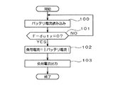
図2は、負荷状態検知部140によって行われる負荷電流検出の動作手順を示す流れ図である。負荷状態検知部140は、電流検出処理部106によって検出されたバッテリ電流を読み込んだ後(ステップ100)、発電制御装置32から送られてきたFデューティ信号に基づいてF−dutyが0であるか否かを判定する(ステップ101)。F−dutyが0でない場合、すなわち、車両用発電機30が発電中であって発電電流が0でない場合には否定判断が行われ、ステップ100に戻ってバッテリ電流の読み込み動作が繰り返される。
FIG. 2 is a flowchart showing an operation procedure of load current detection performed by the load
また、F−dutyが0の場合、すなわち、車両用発電機30が発電停止の状態であって発電電流が0の場合にはステップ101の判定において肯定判断が行われる。次に、負荷状態検知部140は、読み込んだバッテリ電流の絶対値を負荷電流値として算出し(ステップ102)、この算出した負荷電流値を燃費向上制御部150に向けて出力する(ステップ103)。
When F-duty is 0, that is, when the
燃費向上制御部150は、バッテリ状態検知部120、車両状態検知部130、負荷状態検知部140の各検出結果に基づいて、バッテリ10が放電する状況における放電量を予測し、バッテリ10が劣化してしまうSOCよりも、予測した放電量分だけ高いSOCとなるように車両用発電機30の発電状態を制御する。
The fuel efficiency improvement control unit 150 predicts the discharge amount in the situation where the
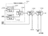
図3は、燃費向上制御部150の詳細構成を示す図である。図3に示すように、燃費向上制御部150は、下限SOC設定部151、発電方式決定部155、発電電圧決定部156を備える。また、下限SOC設定部151は、アイドル時必要SOC算出部152、減速回生期待SOC算出部153、下限SOC決定部154を備えている。
FIG. 3 is a diagram illustrating a detailed configuration of the fuel efficiency improvement control unit 150. As shown in FIG. 3, the fuel efficiency improvement control unit 150 includes a lower limit
アイドル時必要SOC算出部152は、アイドル状態のときにバッテリ10の放電が発生するものと想定し、アイドル時の放電量を予測して、次のアイドル状態になるまでに確保が必要なSOCを「アイドル時必要SOC」として決定する。例えば、SOCが88%以下でバッテリ10の劣化が生じるものとする。
The idle required
(ISS車の場合)
ISS車の場合には、アイドル時にはエンジンが停止して非発電状態になるため、アイドル時必要SOC(%)は以下の式を用いて算出する。
(For ISS cars)
In the case of an ISS vehicle, the engine stops and enters a non-power generation state when idling, so the required SOC (%) during idling is calculated using the following equation.
(非ISS車の場合)
非ISS車の場合には、アイドル時の負荷電流がアイドル時最大発電電流よりも大きいか否かでアイドル時必要SOCの算出方法が異なる。
(For non-ISS cars)
In the case of a non-ISS vehicle, the method for calculating the required SOC during idling differs depending on whether or not the load current during idling is larger than the maximum generated current during idling.
(負荷電流)<(アイドル時の車両用発電機30の出力電流の上限値)の場合には、電気負荷を使ってもSOCが低下しないため、
(アイドル時必要SOC)=88%
となる。
In the case of (load current) <(upper limit value of the output current of the
(Required SOC when idling) = 88%
It becomes.
また、(負荷電流)≧(アイドル時の車両用発電機30の出力電流の上限値)の場合に(車両用発電機30の発電量よりも負荷電流の方が大きい場合)は、アイドル時必要SOCは以下の式を用いて算出する。
Further, when (load current) ≧ (upper limit value of the output current of the
上述した数1、数2に含まれる「アイドル時間」は、将来発生することが予測されるアイドル時間(放電予測時間)であり、想定される走行状態に応じて設定された所定値(例えば、代表的なEUモードやJC08モードにおける最長時間85sを、安全を見込んで1.5倍した時間に近い130sが所定値として用いられる)や、過去のアイドル状態の継続時間の平均値などを、アイドル時間として用いる場合が考えられる。想定される走行状態に応じて設定された所定値を用いる場合には、アイドル時間(放電予測時間)を取得するための特別な処理が不要になり、処理負担の軽減によるコスト低減を図ることができる。また、過去のアイドル状態の継続時間の平均値などの過去の放電状態の継続時間に基づいて設定する場合には、実際の走行状態に合わせた適切な放電予測時間を用いることができ、精度の高い充電制御が可能となる。
The “idle time” included in the above-described
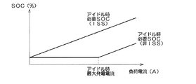
図4は、アイドル時必要SOCと負荷電流との関係を示す図である。図4に示すように、ISS車の場合にはアイドル状態に入ると同時にエンジンが停止し、車両用発電機30の発電も停止するため、その時点からバッテリ10の放電が始まる。したがって、負荷電流に対応する放電量に相当する分だけ高いSOCが必要になる。
FIG. 4 is a diagram showing the relationship between the SOC required during idling and the load current. As shown in FIG. 4, in the case of an ISS vehicle, the engine is stopped at the same time as entering the idle state, and the power generation of the
一方、非ISS車の場合には、負荷電流が車両用発電機30の発電でまかなえる場合には、負荷電流を考慮してSOCを高くしておく必要がないが、負荷電流が車両用発電機30の発電能力(アイドル時最大発電電流)を超える場合にはその超えた分だけ高いSOCが必要になる。
On the other hand, in the case of a non-ISS vehicle, when the load current can be generated by the power generation of the
減速回生期待SOC算出部153は、車両減速時に回生発電を行う場合にその回生発電によって回復が期待されるSOCを減速回生期待SOCとして算出する。例えば、車速が15km/h以下のときには、減速回生期待SOCが0に設定され、車速が15km/hよりも速いときには、以下の式を用いて減速回生期待SOCが算出される。
The deceleration regeneration expected
図5は、上記の式に含まれる回生期待時間の説明図である。図5に示すように、現在の車速から減速を開始した時点から車速が15km/hに達するまでの時間が回生期待時間となる。例えば、EUモードでの減速中の車速変化量平均値である2.9(km/h)/sを用いると、減速回生期待SOCは以下のようになる。 FIG. 5 is an explanatory diagram of the expected regeneration time included in the above equation. As shown in FIG. 5, the time from when the vehicle starts to decelerate from the current vehicle speed until the vehicle speed reaches 15 km / h is the expected regeneration time. For example, using 2.9 (km / h) / s, which is an average value of the vehicle speed change amount during deceleration in the EU mode, the deceleration regeneration expected SOC is as follows.
下限SOC決定部154は、アイドル時必要SOC算出部52によって算出されたアイドル時必要SOCから、減速回生期待SOC算出部153によって算出された減速回生期待SOCを差し引いた値を、下限SOCとして算出する。この下限SOCは、アイドル時に放電されてもSOCがバッテリ劣化が生じる88%を下回らないようにするために、現在のSOCをいくら以上にすればよいかを示すものである。
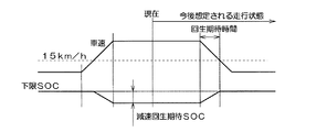
The lower limit
図6は、下限SOCの説明図である。図6に示すように、車速が15km/hを超えると、超えた分に対応して将来、回生発電が行われることになるため、この超えた分だけ下限SOCを低く設定することができる。 FIG. 6 is an explanatory diagram of the lower limit SOC. As shown in FIG. 6, when the vehicle speed exceeds 15 km / h, regenerative power generation will be performed in the future in response to the excess, so the lower limit SOC can be set lower by this excess.
発電方式決定部155は、バッテリ容量検知部120によって検出された現在のSOCと、下限SOC決定部154によって決定された下限SOCと、負荷状態検知部140によって検出された負荷電流とに基づいて、車両用発電機30の発電方法を決定する。
The power generation
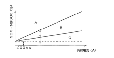
図7は、発電方式決定の説明図である。横軸は負荷電流を、縦軸は現在のSOCから下限SOCを差し引いた値をそれぞれ示している。図7において、Aで示される領域は、現在のSOCに十分な余裕がある場合に対応しており、この場合には、燃費向上を目的として、加速時および定常走行時の両方において発電方式として「発電抑制」が採用される。また、Bで示される領域は、現在のSOCにあまり余裕がなくなった場合に対応しており、この場合には、SOC維持を目的として、加速時における発電方式として「発電抑制」が、定常走行時における発電方式として「定電圧発電」が採用される。また、Cで示される領域は、現在のSOCに余裕がなくなった場合に対応しており、この場合には、SOC回復を目的として、加速時および定常走行時の両方において発電方式として「容量回復発電」が採用される。 FIG. 7 is an explanatory diagram for determining the power generation method. The horizontal axis represents the load current, and the vertical axis represents the value obtained by subtracting the lower limit SOC from the current SOC. In FIG. 7, the region indicated by A corresponds to a case where there is a sufficient margin in the current SOC. In this case, for the purpose of improving fuel consumption, the power generation method is used both during acceleration and during steady running. “Power generation suppression” is adopted. The region indicated by B corresponds to the case where there is not enough room in the current SOC. In this case, for the purpose of maintaining the SOC, “power generation suppression” is used as a power generation method at the time of acceleration. "Constant voltage power generation" is adopted as the power generation method at the time. The region indicated by C corresponds to the case where there is no room in the current SOC. In this case, for the purpose of SOC recovery, “capacity recovery” is used as a power generation method in both acceleration and steady running. "Power generation" is adopted.
なお、図7に含まれる200Asは、EPS(電動パワーステアリング)作動時の電流100Aが1秒継続する場合を想定し、安全率を2としたものであり、短期的に大電力電気負荷が作動してもSOCが88%を下回らないようにするための余裕分である。なお、車両減速時には、現在のSOCが95%よりも低い場合に回生発電を実施する。 Note that 200 As included in FIG. 7 assumes that the current 100A during EPS (electric power steering) operation lasts for 1 second, and the safety factor is set to 2, and a high-power electric load is activated in the short term. Even so, this is a margin to prevent the SOC from falling below 88%. At the time of vehicle deceleration, regenerative power generation is performed when the current SOC is lower than 95%.
例えば、EUモードにおける最長の加速中(41s)でも、加速時に発電抑制を実施することができるSOCを確保することを想定し、領域Aと領域Bの境界が設定される。また、発電停止時にバッテリ10が放電から充電に切り替わるまでの時間を想定し(例えば10s)、領域Bと領域Cの境界が設定される。
For example, even during the longest acceleration (41 s) in the EU mode, the boundary between the region A and the region B is set on the assumption that an SOC capable of suppressing power generation during acceleration is secured. In addition, the boundary between the region B and the region C is set assuming a time until the
また、発電方式決定部155は、減速時には、SOCが所定値を下回っている場合(例えば95%未満の場合)に発電方式として「回生発電」を採用し、SOCが所定値以上の場合には発電方式として「発電抑制」を採用する。
The power generation
発電電圧決定部156は、発電方式決定部155によって決定された発電方式と、温度検出処理部110によって検出されたバッテリ温度と、車両状態検知部130から出力される走行状態信号とに基づいて調整電圧目標値を設定し、電圧変化速度が所定値(例えば2V/s)となるように発電制御装置32に対する調整電圧指示値を決定する。決定した調整電圧指示値は、通信入出力182、LINインタフェース192を介して発電制御装置32に送られる。具体的には、アイドル時、加速/定常走行時、減速時のそれぞれにおける調整電圧目標値が以下のように設定される。
The power generation
(アイドル時)
アイドル時には、調整電圧目標値が12.8Vに設定される。
(When idle)
At the time of idling, the adjustment voltage target value is set to 12.8V.
(加速/定常走行時)
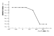
加速時と定常走行時には、以下の表で示される発電方式および調整電圧目標値が設定される。図8は、以下の表に含まれる容量回復発電に対応する調整電圧目標値の具体例を示す図である。
(Acceleration / steady driving)
During acceleration and steady running, the power generation method and the adjustment voltage target value shown in the following table are set. FIG. 8 is a diagram illustrating a specific example of the adjustment voltage target value corresponding to the capacity recovery power generation included in the following table.
図8に示すように、バッテリ10の容量回復が可能な調整電圧はバッテリ温度に依存するため、発電電圧決定部156は、温度検出処理部110によって検出されたバッテリ温度に基づいて、容量回復が可能な調整電圧目標値を設定する。
As shown in FIG. 8, since the adjustment voltage that can recover the capacity of the
(減速時)
減速時に、SOCが95%未満の場合には、発電方式として「回生発電」が設定されるが、この場合には、調整電圧目標値が14.5V+αに設定される。ここで、αは車両用発電機30からバッテリ10までの配線による電圧降下分であり、この電圧降下分を考慮した調整電圧目標値が設定される。
(During deceleration)
If the SOC is less than 95% during deceleration, “regenerative power generation” is set as the power generation method. In this case, the adjustment voltage target value is set to 14.5 V + α. Here, α is a voltage drop due to the wiring from the
一方、減速時に、SOCが95%以上の場合には、発電方式として「発電抑制」が設定されるが、この場合には、調整電圧目標値が12.5Vに設定される。 On the other hand, when the SOC is 95% or more during deceleration, “power generation suppression” is set as the power generation method. In this case, the adjustment voltage target value is set to 12.5V.
このように、本実施形態の充電制御装置100では、大きな負荷電流に応じた適切な発電制御を行うことができ、実用状態においてバッテリ10の容量(SOC)維持と車両の燃費向上を図ることができる。また、アイドルストップ車については、アイドルストップ時の放電量を考慮した発電制御を行うことができるため、アイドルストップ機能を有効に使用することができ、これによる燃費向上を期待することができる。また、負荷電流が小さい場合には、その程度に応じて、余分な発電量を抑制することができるため、これによる燃費向上を期待することができる。さらに、バッテリ劣化が生じない低いバッテリ容量を維持することができるため、回生発電を行う場合にはその発電量を大きく設定することができ、さらに燃費向上を図ることができる。
As described above, the
また、車両用発電機30の発電量よりも負荷電流の方が大きい場合にバッテリ10の放電が発生するため、数2を用いてアイドル時必要SOCを算出することにより、放電する状況を正確にとらえて精度の高い充電制御を行い、バッテリ10の容量維持と車両の燃費向上を確実に実現することができる。
In addition, since the discharge of the
また、アイドル状態において車両用発電機30の回転数が最も低下するため、この状況下で最もバッテリ10の放電が生じやすい。このため、アイドル時の放電を考慮することにより、適切な充電制御を行い、バッテリ10の容量維持と車両の燃費向上を実現することができる。また、アイドル状態の検出は容易であるため、処理負担を軽減することができる。
Further, since the rotational speed of the
また、負荷電流値から放電状況における車両用発電機の最大発電量を差し引いた値に放電予測時間(アイドル時間)を乗算することでバッテリ10の放電量を予測することにより、リアルタイムに実用状態における放電量を予測することができ、精度の高い充電制御を行うことができる。
In addition, by predicting the discharge amount of the
また、バッテリ10に接続された電気負荷に流れる負荷電流を検出する負荷状態検知部140さらに備えることにより、電気負荷の実際の使用状態に応じた正確な放電量を把握することができ、さらに精度の高い充電制御を行うことができる。特に、車両用発電機30が発電していない状態におけるバッテリ10の放電電流を負荷電流値として用いることにより、バッテリ10の充放電電流を検出するだけで負荷電流を把握することができ、直接負荷電流を検出する場合に比べてコスト低減を図ることができる。
Further, by further including a load
また、上述した放電予測時間は、想定される走行状態に応じて設定された所定値を用いることが望ましい。これにより、放電予測時間を取得するための特別な処理が不要になり、処理負担の軽減によるコスト低減を図ることができる。 Moreover, it is desirable to use the predetermined value set according to the driving | running state assumed for the estimated discharge time mentioned above. This eliminates the need for a special process for obtaining the estimated discharge time, thereby reducing the cost by reducing the processing load.
また、上述した充放電予測時間は、過去の放電状態の継続時間に基づいて設定することが望ましい。実際の走行状態に合わせた適切な充電予測時間を用いることができ、精度の高い充電制御が可能となる。 Moreover, it is desirable to set the above-described estimated charge / discharge time based on the duration of the past discharge state. An appropriate estimated charging time according to the actual running state can be used, and charge control with high accuracy is possible.
上述したように、本発明によれば、電気負荷が大きい場合であっても、大きな負荷電流に応じた適切な発電制御を行うことができ、実用状態においてバッテリ10の容量維持と車両の燃費向上を図ることができる。
As described above, according to the present invention, even when the electrical load is large, it is possible to perform appropriate power generation control according to a large load current, maintaining the capacity of the
10 バッテリ
30 車両用発電機
32 発電制御装置
100 充電制御装置
102 シャント抵抗
104 差動増幅器
106 電流検出処理部
108 温度検出部
110 温度検出処理部
120 バッテリ状態検知部
130 車両状態検知部
140 負荷状態検知部
150 燃費向上制御部
151 下限SOC設定部
152 アイドル時必要SOC算出部
153 減速回生期待SOC算出部
154 下限SOC決定部
155 発電方式決定部
156 発電電圧決定部
180、182 通信入出力部(通信I/O)
190 CANインタフェース(CAN I/F)
192 LINインタフェース(LIN I/F)
DESCRIPTION OF
190 CAN interface (CAN I / F)
192 LIN interface (LIN I / F)
Claims (8)
車載バッテリのバッテリ容量を検出するバッテリ状態検知手段と、
前記車載バッテリが放電する状況における放電量を予測し、検出された前記バッテリ容量に基づいて、前記車載バッテリが劣化するバッテリ容量よりも、予測した放電量分だけ高いバッテリ容量となるように目標となるバッテリ容量下限値を設定し、車両用発電機の発電量を車両走行状態毎に制御する発電制御手段と、
を備え、前記放電量は、負荷電流値から放電状況における前記車両用発電機の最大発電量を差し引いた値に放電予測時間を乗算することで予測することを特徴とする充電制御システム。 Vehicle state detection means for detecting the vehicle running state;
Battery state detection means for detecting the battery capacity of the in-vehicle battery;
Predicting the amount of discharge in a situation where the in-vehicle battery is discharged, and based on the detected battery capacity, the target is set to be higher than the battery capacity by which the in-vehicle battery deteriorates by the predicted amount of discharge. A power generation control means for setting the battery capacity lower limit value to control the power generation amount of the vehicle generator for each vehicle running state,
Wherein the discharge amount of the charge control system characterized that you predicted by multiplying the discharge prediction time to a value obtained by subtracting the maximum power generation amount of the generator the vehicle in the discharge status from the load current value.
前記発電制御手段は、前記車両状態検知手段によって検出された車両走行状態が減速を示すときに前記車両用発電機に対して回生発電を指示するとともに、この回生発電によって得られる発電量を用いて前記バッテリ容量下限値を補正することを特徴とする充電制御システム。 In claim 1,
The power generation control unit instructs the vehicle generator to perform regenerative power generation when the vehicle running state detected by the vehicle state detection unit indicates deceleration, and uses a power generation amount obtained by the regenerative power generation. A charge control system for correcting the battery capacity lower limit value.
前記車載バッテリが放電する状況は、負荷電流値と前記車両用発電機の最大発電量とが等しくなる回転数以下の場合であることを特徴とする充電制御システム。 In claim 1 or 2,
The charging control system according to claim 1, wherein the in-vehicle battery is discharged when the load current value is equal to or less than a rotation speed at which the maximum power generation amount of the vehicular generator is equal.
前記車載バッテリが放電する状況は、車両がアイドル状態であることを特徴とする充電制御システム。 In claim 1 or 2,
The charging control system according to claim 1, wherein the vehicle-mounted battery is discharged in an idle state.
前記車載バッテリに接続された電気負荷に流れる負荷電流を検出する負荷状態検知手段をさらに備えることを特徴とする充電制御システム。 In any one of Claims 1-4,
The charging control system further comprising a load state detection means for detecting a load current flowing in an electric load connected to the vehicle battery.
前記負荷状態検知手段は、前記車両用発電機が発電していない状態における前記車載バッテリの放電電流を負荷電流値として用いることを特徴とする充電制御システム。 In claim 5,
The charge control system, wherein the load state detection means uses a discharge current of the in-vehicle battery in a state where the vehicle generator is not generating power as a load current value.
前記放電予測時間は、想定される走行状態に応じて設定された所定値を用いることを特徴とする充電制御システム。 In any one of Claims 1-6,
The charge control system characterized by using a predetermined value set according to an assumed running state as the estimated discharge time.
前記充放電予測時間は、過去の放電状態の継続時間に基づいて設定することを特徴とする充電制御システム。 In any one of Claims 1-6,
The charge / discharge prediction time is set based on a duration of a past discharge state.
Priority Applications (3)
| Application Number | Priority Date | Filing Date | Title |
|---|---|---|---|
| JP2010049712A JP5407945B2 (en) | 2010-03-05 | 2010-03-05 | Charge control system |
| DE102011001038A DE102011001038A1 (en) | 2010-03-05 | 2011-03-02 | Charging control system |
| US13/039,758 US8686692B2 (en) | 2010-03-05 | 2011-03-03 | Charge control system |
Applications Claiming Priority (1)
| Application Number | Priority Date | Filing Date | Title |
|---|---|---|---|
| JP2010049712A JP5407945B2 (en) | 2010-03-05 | 2010-03-05 | Charge control system |
Publications (2)
| Publication Number | Publication Date |
|---|---|
| JP2011188597A JP2011188597A (en) | 2011-09-22 |
| JP5407945B2 true JP5407945B2 (en) | 2014-02-05 |
Family
ID=44530765
Family Applications (1)
| Application Number | Title | Priority Date | Filing Date |
|---|---|---|---|
| JP2010049712A Active JP5407945B2 (en) | 2010-03-05 | 2010-03-05 | Charge control system |
Country Status (3)
| Country | Link |
|---|---|
| US (1) | US8686692B2 (en) |
| JP (1) | JP5407945B2 (en) |
| DE (1) | DE102011001038A1 (en) |
Families Citing this family (16)
| Publication number | Priority date | Publication date | Assignee | Title |
|---|---|---|---|---|
| EP2297622B1 (en) * | 2008-06-26 | 2017-01-25 | General Electric Technology GmbH | A method of estimating the maximum power generation capacity and for controlling a specified power reserve of a single cycle or combined cycle gas turbine power plant, and a power generating system for use with said method |
| WO2012104962A1 (en) * | 2011-01-31 | 2012-08-09 | スズキ株式会社 | Hybrid vehicle |
| US8890467B2 (en) * | 2011-03-28 | 2014-11-18 | Continental Automotive Systems, Inc. | System for controlling battery conditions |
| US9885757B2 (en) * | 2011-04-01 | 2018-02-06 | Atieva, Inc. | Method and apparatus for determining the state-of-charge of a battery |
| JP5811192B2 (en) * | 2012-01-11 | 2015-11-11 | トヨタ自動車株式会社 | Vehicle control apparatus, vehicle, and vehicle control method |
| JP6002962B2 (en) * | 2012-02-18 | 2016-10-05 | 耕一 山野上 | Deceleration energy regeneration system for vehicles |
| JP5965775B2 (en) * | 2012-08-07 | 2016-08-10 | 株式会社デンソー | Vehicle power system |
| JP6044176B2 (en) * | 2012-08-13 | 2016-12-14 | スズキ株式会社 | Vehicle power generation control device |
| JP5831400B2 (en) * | 2012-08-23 | 2015-12-09 | トヨタ自動車株式会社 | Vehicle control apparatus, vehicle, and vehicle control method |
| JP5655050B2 (en) * | 2012-10-11 | 2015-01-14 | 本田技研工業株式会社 | Generator control device |
| JP2016005425A (en) * | 2014-06-19 | 2016-01-12 | 古河電気工業株式会社 | Secondary cell charge/discharge controller and secondary cell charge/discharge control method |
| JP6201968B2 (en) * | 2014-11-27 | 2017-09-27 | トヨタ自動車株式会社 | Charge control device |
| JP6245230B2 (en) | 2015-07-30 | 2017-12-13 | トヨタ自動車株式会社 | Generation voltage control system |
| JP6686395B2 (en) * | 2015-12-01 | 2020-04-22 | オムロン株式会社 | Battery charging device, battery charging system, and battery charging method |
| JP6172321B2 (en) * | 2016-04-18 | 2017-08-02 | トヨタ自動車株式会社 | Vehicle control device and power generation control method |
| JP7087551B2 (en) * | 2018-03-28 | 2022-06-21 | 株式会社デンソー | Control device |
Family Cites Families (17)
| Publication number | Priority date | Publication date | Assignee | Title |
|---|---|---|---|---|
| US4558281A (en) * | 1982-06-12 | 1985-12-10 | Lucas Industries | Battery state of charge evaluator |
| US6256642B1 (en) | 1992-01-29 | 2001-07-03 | Microsoft Corporation | Method and system for file system management using a flash-erasable, programmable, read-only memory |
| JP2001268719A (en) * | 2000-03-23 | 2001-09-28 | Toyota Motor Corp | Battery charging controller for hybrid vehicle |
| JP3582479B2 (en) * | 2000-11-21 | 2004-10-27 | 日産自動車株式会社 | Vehicle battery charge control device |
| JP2003018754A (en) * | 2001-06-27 | 2003-01-17 | Nippon Soken Inc | Estimation-calculating device for battery state of charge |
| JP3891845B2 (en) | 2002-01-15 | 2007-03-14 | 株式会社日本自動車部品総合研究所 | Charge control device for secondary battery for vehicle |
| JP4190766B2 (en) * | 2002-01-25 | 2008-12-03 | 古河電気工業株式会社 | Method and apparatus for estimating remaining capacity of storage battery mounted on vehicle |
| JP3880924B2 (en) * | 2002-12-18 | 2007-02-14 | 松下電器産業株式会社 | Power supply control device and control method thereof |
| US7317300B2 (en) * | 2003-06-23 | 2008-01-08 | Denso Corporation | Automotive battery state monitor apparatus |
| JP4253544B2 (en) * | 2003-08-01 | 2009-04-15 | 株式会社日本自動車部品総合研究所 | Vehicle generator control device |
| KR100692404B1 (en) * | 2004-12-21 | 2007-03-09 | 현대자동차주식회사 | Memory effect prevention of battery charging state calculation Algorithm |
| JP4349400B2 (en) * | 2006-02-28 | 2009-10-21 | トヨタ自動車株式会社 | Vehicle and control method thereof |
| KR100839381B1 (en) * | 2006-11-01 | 2008-06-20 | 삼성에스디아이 주식회사 | Battery management system and driving method thereof |
| JP4771928B2 (en) * | 2006-12-06 | 2011-09-14 | 株式会社オートネットワーク技術研究所 | Power supply |
| US8248023B2 (en) * | 2007-11-04 | 2012-08-21 | GM Global Technology Operations LLC | Method of externally charging a powertrain |
| JP2010041913A (en) * | 2008-07-11 | 2010-02-18 | Panasonic Corp | Vehicular power supply unit |
| TWI404964B (en) * | 2010-04-22 | 2013-08-11 | Ablerex Electronics Co Ltd | Estimation method for residual discharging time of batteries |
-
2010
- 2010-03-05 JP JP2010049712A patent/JP5407945B2/en active Active
-
2011
- 2011-03-02 DE DE102011001038A patent/DE102011001038A1/en not_active Withdrawn
- 2011-03-03 US US13/039,758 patent/US8686692B2/en active Active
Also Published As
| Publication number | Publication date |
|---|---|
| JP2011188597A (en) | 2011-09-22 |
| DE102011001038A1 (en) | 2011-12-29 |
| US20110215764A1 (en) | 2011-09-08 |
| US8686692B2 (en) | 2014-04-01 |
Similar Documents
| Publication | Publication Date | Title |
|---|---|---|
| JP5407945B2 (en) | Charge control system | |
| US10381695B2 (en) | Cooling system for secondary battery | |
| US7531909B2 (en) | Method and apparatus for controlling charging operations for battery | |
| KR101687305B1 (en) | Control device and control method for non-aqueous secondary battery | |
| EP1897745B1 (en) | Vehicle driving system | |
| US10403942B2 (en) | Cooling system for vehicle-mounted secondary battery | |
| JPWO2009013891A1 (en) | Vehicle power supply | |
| JP2008228403A (en) | Power supply device for vehicle | |
| JP5762699B2 (en) | Hybrid car power supply | |
| US20200171975A1 (en) | Vehicle battery heating apparatus | |
| JP2010140762A (en) | Determination device for determining lithium ion battery state | |
| JP2003304604A (en) | Method and apparatus for controlling motor | |
| JP4110979B2 (en) | Vehicle power supply | |
| KR20150121919A (en) | Apparatus for Charging Battery and Method Thereof | |
| JP2018034734A (en) | Control device for hybrid vehicle | |
| JP2020174458A (en) | Battery pack | |
| JP2006123807A (en) | Vehicle control device | |
| JP6607161B2 (en) | In-vehicle battery system control method | |
| KR20190013021A (en) | Eco-friendly vehicle and method of controlling battery thereof | |
| JP6164082B2 (en) | Calculation method of full charge capacity of battery | |
| JP4049044B2 (en) | Voltage generator for vehicle generator | |
| JP4096885B2 (en) | Cooling device for power conversion mechanism mounted on vehicle | |
| JP2008263679A (en) | Lead battery charging controller and lead battery charging control method employing the same | |
| JP6394417B2 (en) | Charge control device | |
| JP2014121131A (en) | Power supply for vehicle and electric vehicle |
Legal Events
| Date | Code | Title | Description |
|---|---|---|---|
| A621 | Written request for application examination |
Free format text: JAPANESE INTERMEDIATE CODE: A621 Effective date: 20120510 |
|
| A977 | Report on retrieval |
Free format text: JAPANESE INTERMEDIATE CODE: A971007 Effective date: 20130716 |
|
| A131 | Notification of reasons for refusal |
Free format text: JAPANESE INTERMEDIATE CODE: A131 Effective date: 20130723 |
|
| A521 | Request for written amendment filed |
Free format text: JAPANESE INTERMEDIATE CODE: A523 Effective date: 20130920 |
|
| TRDD | Decision of grant or rejection written | ||
| A01 | Written decision to grant a patent or to grant a registration (utility model) |
Free format text: JAPANESE INTERMEDIATE CODE: A01 Effective date: 20131008 |
|
| A61 | First payment of annual fees (during grant procedure) |
Free format text: JAPANESE INTERMEDIATE CODE: A61 Effective date: 20131021 |
|
| R151 | Written notification of patent or utility model registration |
Ref document number: 5407945 Country of ref document: JP Free format text: JAPANESE INTERMEDIATE CODE: R151 |
|
| R250 | Receipt of annual fees |
Free format text: JAPANESE INTERMEDIATE CODE: R250 |
|
| R250 | Receipt of annual fees |
Free format text: JAPANESE INTERMEDIATE CODE: R250 |
|
| R250 | Receipt of annual fees |
Free format text: JAPANESE INTERMEDIATE CODE: R250 |
|
| R250 | Receipt of annual fees |
Free format text: JAPANESE INTERMEDIATE CODE: R250 |
|
| R250 | Receipt of annual fees |
Free format text: JAPANESE INTERMEDIATE CODE: R250 |
|
| R250 | Receipt of annual fees |
Free format text: JAPANESE INTERMEDIATE CODE: R250 |
|
| R250 | Receipt of annual fees |
Free format text: JAPANESE INTERMEDIATE CODE: R250 |
|
| R250 | Receipt of annual fees |
Free format text: JAPANESE INTERMEDIATE CODE: R250 |

