JP5407930B2 - Vehicle seal structure and vehicle door - Google Patents
Vehicle seal structure and vehicle door Download PDFInfo
- Publication number
- JP5407930B2 JP5407930B2 JP2010040719A JP2010040719A JP5407930B2 JP 5407930 B2 JP5407930 B2 JP 5407930B2 JP 2010040719 A JP2010040719 A JP 2010040719A JP 2010040719 A JP2010040719 A JP 2010040719A JP 5407930 B2 JP5407930 B2 JP 5407930B2
- Authority
- JP
- Japan
- Prior art keywords
- hole
- door
- vehicle
- base
- general surface
- Prior art date
- Legal status (The legal status is an assumption and is not a legal conclusion. Google has not performed a legal analysis and makes no representation as to the accuracy of the status listed.)
- Expired - Fee Related
Links
Images


Landscapes
- Fittings On The Vehicle Exterior For Carrying Loads, And Devices For Holding Or Mounting Articles (AREA)
Description
本発明は、車両のシール構造及び車両用ドアに関する。 The present invention relates to a vehicle seal structure and a vehicle door.
自動車等の車両の車体やドアの室内側の面を構成する板金パネルには、作業用や部品取付用の開口孔が複数形成されている。 A plurality of opening holes for work and component mounting are formed in a sheet metal panel that constitutes a surface of a vehicle body such as an automobile or the interior side of a door.
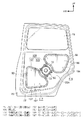
例えば、図12に示すように、車両のリアサイドドアの車室内側を構成するインナパネル820には、スピーカー850が取り付けられる取付孔830及び作業孔822、824、826が形成されている。
取付孔830はスピーカー850が取り付けられることで塞がれてシールされる。一方、作業孔822、824、826はドアインナパネル820にサービスホールカバー828を貼り付けることで塞がれシールされるシール構造が一般的とされている。
For example, as shown in FIG. 12, the
The
そして、特許文献1には、ドアインナパネルの高低差のある面の境界部分において、各面にブチルテープを配置するとともに、両ブチルテープの間に位置するシーリングカバーの部位に破断線を形成することで、高低差のある面にそれぞれ形成された複数の孔を一枚のシーリングカバーで塞ぐシーリングカバー貼付構造が提案されている。 And in patent document 1, in the boundary part of the surface with a height difference of a door inner panel, while arrange | positioning a butyl tape on each surface, a broken line is formed in the site | part of the sealing cover located between both butyl tapes. Thus, a sealing cover pasting structure has been proposed in which a plurality of holes respectively formed on surfaces with different heights are closed with a single sealing cover.
図11には、本発明が適用されていない参考例としての車両用ドア(シール構造)が示されている。図11に示すように、サービスホールカバー180によって塞がれた作業孔110と、スピーカー850が取り付けられることによって塞がれた取付孔部120と、が繋がって構成された開口孔100の場合、スピーカー850と作業孔110との境界部Rにはサービスホールカバー180の貼付代150が形成されない。よって、境界部Rのシール性が低下する。つまり、開口孔100(作業孔110)のシール性が低下する。
FIG. 11 shows a vehicle door (seal structure) as a reference example to which the present invention is not applied. As shown in FIG. 11, in the case of the
本発明は、取付部品が取り付けられ塞がれる第二孔部に第一孔部が繋がった開口孔のシール性を向上させることが課題である。 An object of the present invention is to improve the sealing performance of the opening hole in which the first hole portion is connected to the second hole portion to which the attachment component is attached and blocked.
請求項1の発明は、車両を構成するパネル部材に形成され、第一孔部と前記第一孔部に繋がった第二孔部とを有する開口孔と、前記パネル部材の前記第二孔部に取り付けられ、前記第二孔部を塞ぐ取付部品と、前記取付部品における前記第一孔部との境界部に設けられ、前記パネル部材における前記第一孔部の周囲の一般面と繋がる基部と、前記パネル部材に形成され、前記一般面と反対側に凹み、前記基部が配置される段差部と、前記一般面と前記基部とによって、前記第一孔部の周囲に形成されたシール代に設けられたシール部材と、前記シール部材に貼り付けられ、前記第一孔部を塞ぐシーリングカバーと、を備えている。 According to a first aspect of the present invention, there is provided an opening hole formed in a panel member constituting a vehicle and having a first hole portion and a second hole portion connected to the first hole portion, and the second hole portion of the panel member. And a base part connected to a general surface around the first hole part in the panel member, provided at a boundary part between the attachment part that closes the second hole part and the first hole part in the attachment part. The seal member is formed around the first hole by the stepped portion formed on the panel member, recessed on the opposite side of the general surface, and disposed on the base, and the general surface and the base. A sealing member provided; and a sealing cover that is attached to the sealing member and closes the first hole.
請求項1の発明では、パネル部材の第二孔部は取付部品が取り付けられることで塞がれ、第一孔部はシーリングカバーで塞がれる。 In the first aspect of the invention, the second hole of the panel member is closed by attaching the mounting part, and the first hole is closed by the sealing cover.
パネル部材の第二孔部に取り付けられた取付部品には、第一孔部との境界部に基部が設けられている。取付部品の基部とパネル部材における第一孔部の周囲の一般面とで、第一孔部の周囲にシール代が形成される。そして、シーリングカバーがシール部材に貼り付けられ、第一孔部が塞がれる。 The attachment part attached to the second hole of the panel member is provided with a base at the boundary with the first hole. A seal allowance is formed around the first hole portion at the base portion of the attachment part and the general surface around the first hole portion in the panel member. And a sealing cover is affixed on a sealing member, and a 1st hole is obstruct | occluded.
このように、取付部品と第一孔部との境界部分に、第一孔部を塞ぐシーリングカバーのシール代が形成されるので、取付部品が基部を有していない構成、すなわち、取付部品と第一孔部との境界部分にシール代が無い構成と比較して、開口孔(第一孔部)のシール性が向上する。 Thus, since the seal margin of the sealing cover that closes the first hole portion is formed at the boundary portion between the attachment component and the first hole portion, the configuration in which the attachment component does not have a base, that is, the attachment component and The sealing performance of the opening hole (first hole) is improved as compared with a configuration in which there is no seal allowance at the boundary with the first hole.
請求項2の発明は、前記基部と、前記パネル部材における前記第一孔部の周囲の前記一般面と、が面一又は略面一となるように構成されている。
The invention of
請求項2の発明では、基部とパネル部材における第一孔部の周囲の一般面とが、面一又は略面一となるように構成されている。よって、基部と一般面とで段差がある構成と比較し、基部と一般面とに跨った部位のシール性が向上する。
請求項3の発明は、前記基部と前記段差部との間に、シール材が挟まれている。
In the invention of
In the invention of claim 3, a sealing material is sandwiched between the base portion and the step portion.
請求項4の発明は、車両用ドアを構成するドアインナパネルに形成され、第一孔部と前記第一孔部に繋がった第二孔部とを有する開口孔と、前記ドアインナパネルの前記第二孔部に取り付けられ、前記第二孔部を塞ぐ取付部品と、前記取付部品における前記第一孔部との境界部に設けられ、前記ドアインナパネルにおける前記第一孔部の周囲の一般面と繋がる基部と、前記ドアインナパネルに形成され、前記一般面と反対側に凹み、前記基部が配置される段差部と、前記一般面と前記基部とによって、前記第一孔部の周囲に形成されたシール代に設けられたシール部材と、前記シール部材に貼り付けられ、前記第一孔部を塞ぐシーリングカバーと、を備えている。 The invention of claim 4 is formed in a door inner panel constituting a vehicle door, and has an opening hole having a first hole portion and a second hole portion connected to the first hole portion, and the door inner panel. A general part around the first hole in the door inner panel is provided at a boundary between the attachment part that is attached to the second hole and closes the second hole, and the first hole in the attachment part. A base portion connected to a surface , formed in the door inner panel, recessed on the opposite side to the general surface, and a step portion where the base portion is disposed, and the general surface and the base portion around the first hole portion. A seal member provided at the formed seal margin; and a sealing cover that is attached to the seal member and closes the first hole.
請求項4の発明では、ドアインナパネルの第二孔部は取付部品が取り付けられることで塞がれる。ドアインナパネルの第二孔部に取り付けられた取付部品には、第一孔部との境界部に基部が設けられている。取付部品の基部とドアインナパネルにおける第一孔部の周囲の一般面とで、第一孔部の周囲にシール代が形成される。そして、シーリングカバーをシール部材に貼り付けることで、第一孔部が塞がれる。 In the invention of claim 4 , the second hole portion of the door inner panel is closed by attaching the attachment component. The attachment part attached to the second hole of the door inner panel is provided with a base at the boundary with the first hole. A seal margin is formed around the first hole portion by the base portion of the attachment part and the general surface around the first hole portion in the door inner panel. Then, the first hole is closed by sticking the sealing cover to the sealing member.
このように、取付部品と第一孔部との境界部分に、第一孔部を塞ぐシーリングカバーのシール代が形成されるので、取付部品が基部を有していない構成、すなわち、取付部品と第一孔部との境界部分にシール代が無い構成と比較して、開口孔のシール性が向上し、その結果、車両用ドアのインナパネルに形成された開口孔からの、車室内や車両用ドアの内部への水や埃の侵入が抑制又は防止される。
請求項5に記載の発明は、前記基部と前記段差部との間に、シール材が挟まれている。
Thus, since the seal margin of the sealing cover that closes the first hole portion is formed at the boundary portion between the attachment component and the first hole portion, the configuration in which the attachment component does not have a base, that is, the attachment component and Compared with a configuration in which there is no seal allowance at the boundary portion with the first hole portion, the sealing performance of the opening hole is improved. Intrusion of water and dust into the interior of the door is suppressed or prevented.
In a fifth aspect of the present invention, a sealing material is sandwiched between the base portion and the step portion.
請求項1に記載の発明によれば、取付部品が基部を有していない構成と比較し、開口孔のシール性を向上させることができる。 According to the first aspect of the present invention, the sealing performance of the opening hole can be improved as compared with a configuration in which the attachment component does not have a base.
請求項2に記載の発明によれば、基部と一般面とで段差がある構成と比較し、基部と一般面とに跨った部位のシール性を向上させることができる。
請求項3に記載の発明によれば、基部と段差部との間にシール材が挟まれていない構成と比較し、開口孔のシール性を向上させることができる。
According to invention of
According to the third aspect of the present invention, the sealing performance of the opening hole can be improved as compared with the configuration in which the sealing material is not sandwiched between the base portion and the stepped portion.
請求項4に記載の発明によれば、取付部品が基部を有していない構成と比較し、車室内や車両用ドアの内部への水や埃の侵入を抑制又は防止することができる。
請求項5に記載の発明によれば、基部と段差部との間にシール材が挟まれていない構成と比較し、開口孔のシール性を向上させることができる。
According to the fourth aspect of the present invention, it is possible to suppress or prevent water and dust from entering the vehicle interior and the interior of the vehicle door, as compared with a configuration in which the attachment component does not have a base.
According to the fifth aspect of the present invention, the sealing performance of the opening hole can be improved as compared with the configuration in which the sealing material is not sandwiched between the base portion and the step portion.
図1〜図7を用いて、本発明の実施形態に係る車両のシール構造が適用された車両用ドアについて説明する。なお、各図面において、矢印FRは車体前側方向を示し、矢印UPは車体上側方向を示し、矢印OUTは車両幅方向外側を示す。 A vehicle door to which a vehicle seal structure according to an embodiment of the present invention is applied will be described with reference to FIGS. In each drawing, the arrow FR indicates the vehicle front side direction, the arrow UP indicates the vehicle body upper side direction, and the arrow OUT indicates the vehicle width direction outer side.
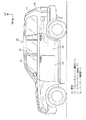
図1に示すように、車両10の左右両側部には、車体の側部の一部を構成するフロントサイドドア12とリアサイドドア14とが、それぞれドアヒンジ回りに開閉可能に設けられている。また、車両10の後部には、バックドア16がドアヒンジ回りに開閉可能に設けられている。
なお、以降の説明における各ドアの方向は、ドアが閉じられた状態(ドア閉止状態)での方向を指すこととする。
また、本実施形態において、フロントサイドドア12のフロントサイドドアガラス13及び、リアサイドドア14のリアサイドガラス15は昇降可能とされている。更に、バックドア16のバックドアガラス17も昇降可能とされている。
As shown in FIG. 1, a
In the following description, the direction of each door refers to the direction in a state where the door is closed (door closed state).
In the present embodiment, the front
左右のフロントサイドドア12及びリアサイドドア14、更にバックドア16の各ドアそれぞれに、取付部品の一例としてのスピーカーが取り付けられ、各ドアそれぞれに本発明のシール構造が適用されている。しかし、以下の説明では、右側のリアサイドドア14を代表して説明する。
Speakers as an example of attachment parts are attached to the left and right
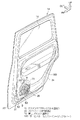
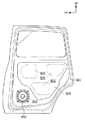
図2〜図4に示すように、リアサイドドア14は、ドア外側(車両幅方向外側)を構成する板金製のドアアウタパネル20と、ドアアウタパネル20の車室内側(車両幅方向内側)に配設された板金製のドアインナパネル22とを備えている。ドアアウタパネル20とドアインナパネル22とは、外周縁同士がヘミング加工等によって接合されている。
As shown in FIGS. 2 to 4, the
図2と図3とに示すように、ドアインナパネル22の車室内側には、ドアトリム24が設けられている。ドアトリム24は、外周縁部がドアインナパネル22の縦壁部等に固定されている。
As shown in FIGS. 2 and 3, a
本実施形態では、ドアトリム24は樹脂製とされ、ドアインナパネル22に取り付けられたスピーカー50(詳細は後述する)に対応する部位26が、若干車室内側に膨出するとともに、小さな孔が複数形成されたメッシュ構造とされている。
In this embodiment, the door trim 24 is made of resin, and a
ドアアウタパネル20とドアインナパネル22と間に形成される空間28(図7参照)には、リアサイドガラス15を昇降させるウインドウレギュレータ、各種電気部品、及び配線等のドア内装部品が配置されている。なお、これらのドア内装部品はドアアウタパネル20に取り付けられている。
In a space 28 (see FIG. 7) formed between the door
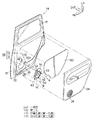
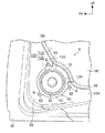
図3に示すように、本実施形態では、ドアインナパネル22には、作業孔部(サービスホール)110と取付孔部120とが繋がった大きな開口孔100が一つ形成されている。
As shown in FIG. 3, in the present embodiment, the door
図3と図4とに示すように、作業孔部(サービスホール)110は、ドア内装部品を、ドアアウタパネル20とドアインナパネル22との間に挿入し、ドアアウタパネル20に取り付けるために形成されている。
As shown in FIG. 3 and FIG. 4, the work hole (service hole) 110 is formed to insert a door interior part between the door
取付孔部120には、スピーカー50が取り付けられる。なお、以降、スピーカー50の方向を説明する場合、図3等に示す取付孔部120にスピーカー50が取り取り付けられた状態での方向を指すこととする。
The
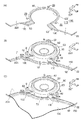
図3、図5、図6等に示すように、スピーカー50は、コーン紙等を有するスピーカー本体52と、スピーカー本体52から径方向(ドアインナパネル22の面内方向)の外側に向かって張り出した第一フランジ60及び第二フランジ70と、を備えている。
As shown in FIGS. 3, 5, 6, and the like, the
第一フランジ60は、スピーカー本体52の外周の約3/4周に亘って設けられている。第一フランジ60には径方向(ドアインナパネル22の面内方向)の外側に突出した取付部62が複数(本実施形態では三箇所)形成されている。また、ドアインナパネル22の取付孔部120の周囲には、ビスQが螺合するビス孔29(図3、図5(A)参照)が形成されている。
The
第二フランジ70は、側面視において略扇形状の板状とされ、第一フランジ60よりも径方向外側に張り出している。また、第二フランジ70の両端部70Aは、第一フランジ60の両端部60Aの車両幅方向外側面(裏面)に接合されている。つまり、第二フランジ70はスピーカー50(スピーカー本体52)と一体化されている。
The
なお、本実施形態では、スピーカー50の第二フランジ70は、第一フランジ60の端部60Aに接合された構成であるがこれに限定されない。
例えば、スピーカー50の第一フランジ60の一部が径方向外側に張り出すことによって、第二フランジ70が形成された構成であってもよい。つまり、第一フランジ60と第二フランジ70とが一体成形された構成であってもよい。
In the present embodiment, the
For example, a configuration in which the
そして、スピーカー50は、ドアインナパネル22における取付孔部120の周囲の一般面22AにビスQによって取り付けられている。
The
なお、図6(A)と図7とに示すように、ドアインナパネル22における取付孔部120の周囲の一般面22Aとスピーカー50の第一フランジ60との間には、防水性のシール材90が挟み込まれている。
As shown in FIGS. 6A and 7, a waterproof sealant is provided between the
よって、開口孔100を構成する取付孔部120は、スピーカー50を取り付けることによって塞がれシールされる。なお、一般面22A(又は第一フランジ60)にシール剤が塗布されることによってシール材90が形成されてもよい。
Therefore, the
図6に示すように、ドアインナパネル22における作業孔部110と取付孔部120との境界部分には、車両幅方向外側に凹んだ段差部130が形成されている。そして、この段差部130にスピーカー50の第二フランジ70が配置される。
As shown in FIG. 6, a stepped
よって、図4、図6(B)、図6(C)に示すように、段差部130間に、スピーカー50の第二フランジ70が掛け渡され、作業孔110の周囲の一般面22Aと第二フランジ70とが繋がり、一般面22Aと第二フランジ70とで作業孔110の周囲に貼付代150が形成される。貼付代150は、作業孔110の全周に亘って(作業孔110の周囲を囲むように)が形成される。別の言い方をすると、サービスホールカバー180の外周部に対応する部位に貼付代150が形成される。
Therefore, as shown in FIGS. 4, 6 </ b> B, and 6 </ b> C, the
なお、段差部130と第二フランジ70との間には、シール材90(図6(A)参照)が挟まれている。
Note that a sealing material 90 (see FIG. 6A) is sandwiched between the stepped
また、図6(B)と図7とに示すように、ドアインナパネル22における作業孔部110の周囲の一般面22Aとスピーカー50の第二フランジ70とは、面一又は略面一となるように、構成されている。
なお、本実施形態では、シール材90の厚み等を考慮し、第一フランジ60と第二フランジ70との間に調整部65(図7参照)を設けることによって、面一又は略面一となるように、調整されている。
Further, as shown in FIGS. 6B and 7, the
In the present embodiment, in consideration of the thickness of the sealing
貼付代150に、シール部材の一例としてのブチルゴム92(防水性接着剤、図7参照)が貼り付けられ、図4、図5、図6(B)、図7等に示すように、このブチルゴム92によって、ビニール等で構成されたシート状のサービスホールカバー180の外周部が貼り付けられている(サービスホールカバー18が貼着されている)。これによって、開口孔100を構成する作業孔部110がサービスホールカバー180によって塞がれシールされている。
A butyl rubber 92 (waterproof adhesive, see FIG. 7) as an example of a sealing member is attached to the
つぎに、スピーカー50の取り付け工程及びサービスホールカバー180の貼り付け工程について説明する。なお、ここで説明する工程は、一例であってこれに限定されるものではない。
Next, the attaching process of the
図3、図6(A)、図6(B)に示すように、開口孔100を構成する取付孔部120の周囲(又はスピーカー50の第一フランジ60の裏面(車両幅方向外側の面))にシール材90(図7参照)を貼り付ける(或いは、シール剤を塗布する)。また、段差部130(又はスピーカー50の第二フランジ70)にシール材90(図7参照)を貼り付ける(或いは、シール剤を塗布する)。その後、取付孔部120にスピーカー50を取り付け、ビスQで固定する。
As shown in FIG. 3, FIG. 6A, and FIG. 6B, the periphery of the mounting
図3、図6(B)、図6(C)に示すように、開口孔100を構成する作業孔部110の周囲の一般面22Aとスピーカー50の第二フランジ70とで形成された貼付代150にブチルゴム92(図7参照)を貼り付ける。そして、ビニール等で構成されたシート状のサービスホールカバー180の外周部を貼り付ける。
As shown in FIGS. 3, 6 </ b> B, and 6 </ b> C, the pasting allowance formed by the
つぎに本実施形態の作用及び効果について説明する。
開口孔100を構成する取付孔部120はスピーカー50を取り付けることで塞がれる。スピーカー50には、作業孔部110との境界部に第二フランジ70が設けられている。このスピーカー50の第二フランジ70とドアインナパネル22における作業孔部110の周囲の一般面22Aとで、作業孔部110の全周に亘って貼付代150が形成される。そして、この作業孔部110の周囲の貼付代150にブチルゴム92を貼り付け、このブチルゴム92にサービスホールカバー180を貼り付けることで、作業孔部110が塞がれシールされる。つまり、サービスホールカバー180の外周部の全周がブチルゴム92で貼り付けられている。
Next, the operation and effect of this embodiment will be described.
The
このように、スピーカー50と作業孔部110との境界部分に、作業孔部110を塞ぐサービスホールカバー180の貼付代150が形成されるので、図11に示す参考例のように第二フランジ70を有していないスピーカー850の構成、すなわち、スピーカー850と作業孔部110との境界部Rに貼付代150が形成されていない構成と比較して、作業孔部110(開口孔100全体)のシール性が向上する。
In this way, since the
また、ドアインナパネル22における作業孔部110の周囲の一般面22Aとスピーカー50の第二フランジ70とは、面一又は略面一となるように構成されている(図6及び図7参照)。よって、一般面22Aと第二フランジ70との境界部分には段差が全くないか、又は殆ど段差がないので、一般面22Aと第二フランジ70との境界部分のシール性が向上する。
Further, the
このようにドアインナパネル22に形成された開口孔100は、スピーカー50とサービスホールカバー180とで塞がれ、サービスホールカバー180の全周に亘ってブチルゴム92で貼り付けられシールされている。よって、第二フランジ70が設けられていない構成と比較し、開口孔100からの車室内やリアサイドドア14の内部への水や埃の浸入が抑制又は防止される。
Thus, the
なお、作業性の向上や軽量化のため作業孔を大きくしていくと、本実施形態のように作業孔が取付孔に繋がってしまう。しかし、上述したように、作業孔を大きくし、取付孔と繋がっても、シール性が確保される。言い換えると、本発明を適用することで、作業孔(開口孔)の大口径化(作業性や軽量化の向上)とシール性の確保とを両立させることができる。 In addition, when the work hole is enlarged for improving workability and weight reduction, the work hole is connected to the mounting hole as in the present embodiment. However, as described above, even if the work hole is enlarged and connected to the mounting hole, the sealing performance is ensured. In other words, by applying the present invention, it is possible to achieve both increase in the diameter of the working hole (opening hole) (improvement in workability and weight reduction) and securing of sealing performance.
また、本実施形態においては、第二フランジ70はスピーカー50と一体化されている。これに対して、例えば、第二フランジ70が一体化されていない別部材とされた構成の場合、スピーカーの取付工程とは別工程で、第二フランジ(基部)70を取り付ける必要ある。よって、本実施形態のように第二フランジ70がスピーカー50と一体化された構成とすることで、組立工程における作業性が向上する。また、部品点数が削減される。
In the present embodiment, the
ここで、上記実施形態では、図3等に示すように、ドアインナパネル22には、一つの作業孔部110と一つ取付孔部120とで構成された大きな開口孔100が一つ形成されていたが、これに限定されない。
Here, in the above embodiment, as shown in FIG. 3 and the like, the door
例えば、一つの作業孔部(第一孔部)と複数の取付孔部(第二孔部)とで構成された開口孔であってもよい。 For example, the opening hole comprised by one work hole part (1st hole part) and several attachment hole parts (2nd hole part) may be sufficient.
例えば、図8に示す第一変形例のように、一つの作業孔部110と二つの取付孔部120、122とで構成された開口孔102であってもよい。
この場合、取付孔部122に取り付けられ且つ取付孔部122を塞ぐスピーカー51にも、スピーカー50と同様に、貼付代150を形成する第二フランジ72が設けられている。よって、作業孔部110の全周に亘って貼付代150が形成され、この貼付代150にブチルゴム92によってサービスホールカバー180を貼り付けることで、作業孔部110が塞がれシールされている。
For example, as in the first modification shown in FIG. 8, the
In this case, the
また、例えば、複数の作業孔部(第一孔部)を一枚のサービスホールカバーで塞ぐ構成であってもよい。 For example, the structure which closes a some work hole part (1st hole part) with one sheet of service hole covers may be sufficient.
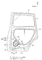
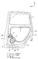
例えば、図9に示す第二変形例のように、作業孔部112と取付孔部120とで構成された開口孔104と、作業孔部114と取付孔部122とで構成された開口孔106と、作業孔118と、の三つの孔がドアナドアインナパネル22に形成され、これら作業孔部112、114、118が一枚のサービスホールカバー184で塞がれている。
なお、作業孔部112、114、118の周囲(サービスホールカバー184の外周部に対応する部位)には、貼付代159が形成され、貼付代159にブチルゴム92が貼り付けられることによって、これら作業孔部112、114、118が一枚のサービスホールカバー184で塞がれシールされている。
For example, as in the second modification shown in FIG. 9, the
In addition, an
また、例えば、一つの取付孔部に複数の作業孔部が繋がった構成の開口孔であってもよい。言い換えると、一の作業孔部に繋がった取付孔部が、別の作業孔部と繋がった構成の開口孔であってもよい。 Further, for example, an opening hole having a configuration in which a plurality of work hole portions are connected to one mounting hole portion may be used. In other words, the mounting hole connected to one work hole may be an opening hole having a configuration connected to another work hole.
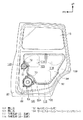
例えば、図10に示す第三変形例のように、ドアナドアインナパネル22に、作業孔部116と取付孔部120とで構成された開口孔部105と、作業孔部117と取付孔部120とで構成された開口孔部107と、が繋がって構成された開口孔109が形成されていてもよい。
For example, as in the third modification shown in FIG. 10, the door
すなわち、取付孔部12に作業孔116と作業孔117が繋がった開口孔109が形成されていてもよい。別の言い方をすると、作業孔部116に取付孔部120が作業孔部117と繋がって構成された開口孔109であってもよい。
That is, the
作業孔部116、117の周囲には、それぞれ貼付代156、157が形成されている。そして、貼付代156、157それぞれにブチルゴム92(図7参照)が貼り付けられるとともに、それぞれサービスホールカバー186、187が貼り付けられ、作業孔部116、117が塞がれシールされている。
尚、本発明は上記実施形態に限定されない。本発明の要旨を逸脱しない範囲において種々なる態様で実施し得ることは言うまでもない。 The present invention is not limited to the above embodiment. Needless to say, various embodiments can be implemented without departing from the scope of the present invention.
例えば、上記実施形態では、シーリングカバーの一例としてのサービスホールカバーは、ブチルゴム92で貼り付けられていたがこれに限定されない。ブチルゴム以外のシール部材、例えば、防水性の接着剤で貼り付けられていてもよい。
For example, in the above embodiment, the service hole cover as an example of the sealing cover is pasted with the
例えば、上記実施形態では、シーリングカバーの一例としてのサービスホールカバーは、ビニール製のシート状であったがこれに限定されない。ビニール以外の種々の材質で構成されていてもてよい。また、シート状でなく、樹脂や金属などで構成されたパネル状のシーリングカバーであってもよい。 For example, in the above embodiment, the service hole cover as an example of the sealing cover is in the form of a vinyl sheet, but is not limited thereto. You may be comprised with various materials other than vinyl. Further, it may be a panel-shaped sealing cover made of resin or metal instead of a sheet.
なお、シーリングカバーの構成に応じて、取り付け方法やシール部材を適宜選択すればよい。例えば、シーリングカバーがパネル状の場合、ブチルゴム92で貼り付けるとともに、ネジ止めして固定してもよい。
In addition, what is necessary is just to select an attachment method and a sealing member suitably according to the structure of a sealing cover. For example, when the sealing cover has a panel shape, it may be attached with
また、例えば、上記実施形態では第二孔部の一例としての取付孔部には、スピーカーが取り付けられたがこれに限定されない。他の部品が取り付けられてもよい。また、第一孔部は、作業孔部(作業孔用の孔)以外の孔、例えば、車両用ドア(車両)の軽量化のために、ドアインナパネルにあけた孔であってもよい。 Further, for example, in the above embodiment, the speaker is attached to the attachment hole as an example of the second hole, but the present invention is not limited to this. Other parts may be attached. The first hole may be a hole other than the work hole (work hole), for example, a hole formed in the door inner panel in order to reduce the weight of the vehicle door (vehicle).
また、上記実施形態では、本発明をリアサイドドア14に適用した形態について説明したが、これに限定されない。前述したように、フロントサイドドア12(図1参照)やバックドア16(図1参照)にも適用できることは言うまでもない。
Moreover, although the said embodiment demonstrated the form which applied this invention to the
更に、その他、車両を構成する板金や樹脂製のパネル部材に対しも、本発明を適用することができる。例えば、インストルメントパネルにおいて、第二孔部としての、ブレーキホースなどが取り付けられる孔やエアコンのブースターが取り付けられる孔等が繋がって構成された開口孔のシール構造にも本発明を適用することができる。 Furthermore, the present invention can also be applied to sheet metal and resin panel members constituting the vehicle. For example, in the instrument panel, the present invention can be applied to a sealing structure of an opening hole formed by connecting a hole to which a brake hose or the like is attached or a hole to which an air conditioner booster is attached as the second hole. it can.
10 車両
12 フロントサイドドア(車両用ドア)
14 リアサイドドア(車両用ドア)
16 バックドア(車両用ドア)
22 ドアインナパネル(パネル部材)
22A 一般面
50 スピーカー(取付部品)
51 スピーカー(取付部品)
55 スピーカー(取付部品)
70 第二フランジ(基部)
72 第二フランジ(基部)
92 ブチルゴム(シール部材)
100 開口孔
102 開口孔
104 開口孔
106 開口孔
109 開口孔
110 作業孔部(第一孔部)
112 作業孔部(第一孔部)
114 作業孔部(第一孔部)
116 作業孔部(第一孔部)
117 作業孔部(第一孔部)
120 取付孔部(第二孔部)
122 取付孔部(第二孔部)
150 貼付代(シール代)
156 貼付代(シール代)
157 貼付代(シール代)
159 貼付代(シール代)
180 サービスホールカバー(シーリングカバー)
184 サービスホールカバー(シーリングカバー)
186 サービスホールカバー(シーリングカバー)
187 サービスホールカバー(シーリングカバー)
10
14 Rear side door (vehicle door)
16 Back door (vehicle door)
22 Door inner panel (panel member)
22A General surface 50 Speaker (Mounting parts)
51 Speaker (Mounting parts)
55 Speaker (Mounting parts)
70 Second flange (base)
72 Second flange (base)
92 Butyl rubber (seal member)
DESCRIPTION OF
112 Working hole (first hole)
114 Working hole (first hole)
116 working hole (first hole)
117 Working hole (first hole)
120 Mounting hole (second hole)
122 Mounting hole (second hole)
150 Sticking fee (seal fee)
156 Sticking fee (seal fee)
157 Sticking fee (seal fee)
159 Adhesive fee (seal fee)
180 Service hole cover (ceiling cover)
184 Service hole cover (ceiling cover)
186 Service hole cover (ceiling cover)
187 Service hole cover (ceiling cover)
Claims (5)
前記パネル部材の前記第二孔部に取り付けられ、前記第二孔部を塞ぐ取付部品と、
前記取付部品における前記第一孔部との境界部に設けられ、前記パネル部材における前記第一孔部の周囲の一般面と繋がる基部と、
前記パネル部材に形成され、前記一般面と反対側に凹み、前記基部が配置される段差部と、
前記一般面と前記基部とによって、前記第一孔部の周囲に形成されたシール代に設けられたシール部材と、
前記シール部材に貼り付けられ、前記第一孔部を塞ぐシーリングカバーと、
を備える車両のシール構造。 An opening hole formed in a panel member constituting the vehicle and having a first hole part and a second hole part connected to the first hole part;
An attachment part that is attached to the second hole of the panel member and closes the second hole,
A base portion provided at a boundary portion with the first hole portion in the mounting part, and connected to a general surface around the first hole portion in the panel member;
A stepped portion formed on the panel member, recessed on the opposite side of the general surface, and the base is disposed,
A seal member provided at a seal margin formed around the first hole by the general surface and the base;
A sealing cover that is attached to the sealing member and closes the first hole;
A vehicle seal structure comprising:
請求項1又は請求項2に記載の車両のシール構造。 The vehicle seal structure according to claim 1 or 2.
前記ドアインナパネルの前記第二孔部に取り付けられ、前記第二孔部を塞ぐ取付部品と、 An attachment part attached to the second hole of the door inner panel and closing the second hole,
前記取付部品における前記第一孔部との境界部に設けられ、前記ドアインナパネルにおける前記第一孔部の周囲の一般面と繋がる基部と、 A base portion provided at a boundary portion with the first hole portion in the mounting part, and connected to a general surface around the first hole portion in the door inner panel;
前記ドアインナパネルに形成され、前記一般面と反対側に凹み、前記基部が配置される段差部と、 A stepped portion formed on the door inner panel, recessed on the opposite side of the general surface, and the base is disposed,
前記一般面と前記基部とによって、前記第一孔部の周囲に形成されたシール代に設けられたシール部材と、 A seal member provided at a seal margin formed around the first hole by the general surface and the base;
前記シール部材に貼り付けられ、前記第一孔部を塞ぐシーリングカバーと、 A sealing cover that is attached to the sealing member and closes the first hole;
を備える車両用ドア。 A vehicle door comprising:
請求項4に記載の車両用ドア。 The vehicle door according to claim 4.
Priority Applications (1)
| Application Number | Priority Date | Filing Date | Title |
|---|---|---|---|
| JP2010040719A JP5407930B2 (en) | 2010-02-25 | 2010-02-25 | Vehicle seal structure and vehicle door |
Applications Claiming Priority (1)
| Application Number | Priority Date | Filing Date | Title |
|---|---|---|---|
| JP2010040719A JP5407930B2 (en) | 2010-02-25 | 2010-02-25 | Vehicle seal structure and vehicle door |
Publications (2)
| Publication Number | Publication Date |
|---|---|
| JP2011173567A JP2011173567A (en) | 2011-09-08 |
| JP5407930B2 true JP5407930B2 (en) | 2014-02-05 |
Family
ID=44686858
Family Applications (1)
| Application Number | Title | Priority Date | Filing Date |
|---|---|---|---|
| JP2010040719A Expired - Fee Related JP5407930B2 (en) | 2010-02-25 | 2010-02-25 | Vehicle seal structure and vehicle door |
Country Status (1)
| Country | Link |
|---|---|
| JP (1) | JP5407930B2 (en) |
Families Citing this family (2)
| Publication number | Priority date | Publication date | Assignee | Title |
|---|---|---|---|---|
| JP5625386B2 (en) * | 2010-02-25 | 2014-11-19 | トヨタ自動車株式会社 | Service hall seal structure |
| JP5670278B2 (en) | 2011-08-09 | 2015-02-18 | 株式会社日立ハイテクノロジーズ | Nanopore analyzer |
Family Cites Families (2)
| Publication number | Priority date | Publication date | Assignee | Title |
|---|---|---|---|---|
| JP2004166064A (en) * | 2002-11-14 | 2004-06-10 | Pioneer Electronic Corp | Inner panel and speaker |
| JP4773900B2 (en) * | 2006-07-04 | 2011-09-14 | 本田技研工業株式会社 | Vehicle door structure |
-
2010
- 2010-02-25 JP JP2010040719A patent/JP5407930B2/en not_active Expired - Fee Related
Also Published As
| Publication number | Publication date |
|---|---|
| JP2011173567A (en) | 2011-09-08 |
Similar Documents
| Publication | Publication Date | Title |
|---|---|---|
| JP6051070B2 (en) | Vehicle window member fixing structure | |
| JP2003054329A (en) | Roof side structure of automobile | |
| JP6383770B2 (en) | Door hole seal | |
| JP4661515B2 (en) | Vehicle door structure | |
| JP5407930B2 (en) | Vehicle seal structure and vehicle door | |
| CN106937186B (en) | Vehicle speaker | |
| JP2013199187A (en) | Rear glass for vehicle, and method of mounting the same | |
| JP2011162146A (en) | Automotive door structure | |
| JP4453549B2 (en) | Vehicle door seal structure | |
| JP4773900B2 (en) | Vehicle door structure | |
| JP4725388B2 (en) | Vehicle door structure | |
| CN105593042B (en) | Vehicle door | |
| WO2015147250A1 (en) | Vehicular door structure | |
| JP2010274709A (en) | Glass run and weather strip mounting structure | |
| JP2011011566A (en) | Door weather strip | |
| JPS5844489B2 (en) | Instrument panel mounting structure | |
| JP2021154829A (en) | Backdoor structure | |
| JPH027058Y2 (en) | ||
| JP2015024676A (en) | Panel structure of sun roof | |
| JP2016068573A (en) | Side visor attachment structure | |
| US6929307B1 (en) | Vehicle door | |
| JP5785068B2 (en) | Division bar | |
| JP7339892B2 (en) | Automobile door seal structure | |
| JP6745451B2 (en) | Folding door with window | |
| CN206226648U (en) | A loudspeaker fixing structure |
Legal Events
| Date | Code | Title | Description |
|---|---|---|---|
| A621 | Written request for application examination |
Free format text: JAPANESE INTERMEDIATE CODE: A621 Effective date: 20120220 |
|
| A977 | Report on retrieval |
Free format text: JAPANESE INTERMEDIATE CODE: A971007 Effective date: 20130515 |
|
| A131 | Notification of reasons for refusal |
Free format text: JAPANESE INTERMEDIATE CODE: A131 Effective date: 20130528 |
|
| A521 | Written amendment |
Free format text: JAPANESE INTERMEDIATE CODE: A523 Effective date: 20130711 |
|
| A01 | Written decision to grant a patent or to grant a registration (utility model) |
Free format text: JAPANESE INTERMEDIATE CODE: A01 Effective date: 20131008 |
|
| A61 | First payment of annual fees (during grant procedure) |
Free format text: JAPANESE INTERMEDIATE CODE: A61 Effective date: 20131021 |
|
| LAPS | Cancellation because of no payment of annual fees |