JP5405583B2 - Casting shroud, operating device for the shroud and device for driving a valve - Google Patents
Casting shroud, operating device for the shroud and device for driving a valve Download PDFInfo
- Publication number
- JP5405583B2 JP5405583B2 JP2011536776A JP2011536776A JP5405583B2 JP 5405583 B2 JP5405583 B2 JP 5405583B2 JP 2011536776 A JP2011536776 A JP 2011536776A JP 2011536776 A JP2011536776 A JP 2011536776A JP 5405583 B2 JP5405583 B2 JP 5405583B2
- Authority
- JP
- Japan
- Prior art keywords
- shroud
- valve
- casting
- piston
- drive
- Prior art date
- Legal status (The legal status is an assumption and is not a legal conclusion. Google has not performed a legal analysis and makes no representation as to the accuracy of the status listed.)
- Expired - Fee Related
Links
Images


Classifications
-
- B—PERFORMING OPERATIONS; TRANSPORTING
- B22—CASTING; POWDER METALLURGY
- B22D—CASTING OF METALS; CASTING OF OTHER SUBSTANCES BY THE SAME PROCESSES OR DEVICES
- B22D41/00—Casting melt-holding vessels, e.g. ladles, tundishes, cups or the like
- B22D41/50—Pouring-nozzles
- B22D41/56—Means for supporting, manipulating or changing a pouring-nozzle
-
- B—PERFORMING OPERATIONS; TRANSPORTING
- B22—CASTING; POWDER METALLURGY
- B22D—CASTING OF METALS; CASTING OF OTHER SUBSTANCES BY THE SAME PROCESSES OR DEVICES
- B22D11/00—Continuous casting of metals, i.e. casting in indefinite lengths
- B22D11/10—Supplying or treating molten metal
- B22D11/106—Shielding the molten jet
-
- B—PERFORMING OPERATIONS; TRANSPORTING
- B22—CASTING; POWDER METALLURGY
- B22D—CASTING OF METALS; CASTING OF OTHER SUBSTANCES BY THE SAME PROCESSES OR DEVICES
- B22D41/00—Casting melt-holding vessels, e.g. ladles, tundishes, cups or the like
- B22D41/50—Pouring-nozzles
Landscapes
- Engineering & Computer Science (AREA)
- Mechanical Engineering (AREA)
- Casting Support Devices, Ladles, And Melt Control Thereby (AREA)
- Continuous Casting (AREA)
- Lift Valve (AREA)
- Valve Housings (AREA)
- Furnace Charging Or Discharging (AREA)
- Manipulator (AREA)
Description
本発明は、液体金属の連続鋳造の技術分野に関するものであり、具体的には、液体金属が上方冶金容器から下方冶金容器に移送されるときに前記金属の再酸化を避けるように構成されたシュラウドと、このようなシュラウドのための操作装置とに関する。 The present invention relates to the technical field of continuous casting of liquid metal, specifically configured to avoid reoxidation of the metal when the liquid metal is transferred from the upper metallurgical vessel to the lower metallurgical vessel. The present invention relates to a shroud and an operating device for such a shroud.
以下の記述では、本発明を制限するものとして解釈されることなく、鋳造取瓶とタンディッシュとの間でのスチールの鋳造で使用されるこのようなシュラウドについてさらに具体的に参照される。 In the following description, reference will be made more specifically to such shrouds used in the casting of steel between a casting jar and a tundish, without being construed as limiting the invention.
鋳造モールド内部に液体金属を分布することを目的とし、液体金属を鋳造取瓶からタンディッシュまで移送することできる、液体金属、特に液体スチールを鋳造するための設備が先行技術において公知である。取瓶からタンディッシュまでの液体の移送のために、鋳造取瓶の底壁に配置された流れ制御バルブに押圧されている、取瓶シュラウドと呼ばれる円筒形シュラウドが一般的に使用される。 Equipment for casting liquid metal, in particular liquid steel, is known in the prior art, which aims to distribute the liquid metal inside the casting mold and can transfer the liquid metal from the casting bottle to the tundish. For the transfer of liquid from the bottle to the tundish, a cylindrical shroud called a bottle shroud is generally used, which is pressed against a flow control valve located on the bottom wall of the casting bottle.
「摺動ゲートバルブ」と呼ばれる流れ制御バルブには、一方のプレートを他方のプレートに対して摺動させる重ね合わされた2つのプレートが設けられ、それにより、バルブは鋳造取瓶を変位することができる際の閉鎖構成と、液体金属がタンディッシュの内部に移送されるように通過することができる開放構成とを取ることができる。閉鎖構成又は開放構成へのバルブの移動は、しばしば液圧ジャッキの形である駆動手段によってもたらされる。駆動手段ができるだけバルブの近くに配置されるために、駆動手段は、取瓶がタンディッシュの近くに達したその瞬間に、鋳造取瓶に又は直接バルブに取り付けられる。 A flow control valve, referred to as a “sliding gate valve”, is provided with two superimposed plates that slide one plate relative to the other so that the valve can displace the casting jar. A closed configuration when possible and an open configuration through which liquid metal can be transferred to the interior of the tundish can be taken. Movement of the valve to a closed or open configuration is often provided by drive means that are in the form of a hydraulic jack. In order for the drive means to be located as close as possible to the valve, the drive means is attached to the casting bottle or directly to the valve at the moment when the bottle reaches near the tundish.
さらに、鋳造取瓶がタンディッシュの上に移動されると、取瓶シュラウドはさらに、取瓶シュラウドを下方プレート又はコレクタノズル(une busette collectrice)などのノズルに対して保持するバルブの下に移動され、それを延ばす。取瓶シュラウドをバルブに対して保持する作用を、設備の床に配置された操作装置を用いて自動的に、又は手動で行うことができる。 Furthermore, when the casting bottle is moved over the tundish, the bottle shroud is further moved under a valve that holds the bottle shroud against a nozzle such as a lower plate or a collector nozzle (une burstet collection). Extend it. The action of holding the bin shroud against the valve can be performed automatically or manually using an operating device located on the floor of the facility.
本発明の目的は、具体的には、シュラウドのための操作装置であって、鋳造行程の際に行われるべき作用の数を制限しつつ、流れ制御バルブにできるだけ近づいてシュラウドを保持することができる、操作装置を提供することにある。 The object of the present invention is specifically an operating device for a shroud, which holds the shroud as close as possible to the flow control valve while limiting the number of actions to be performed during the casting stroke. An object of the present invention is to provide an operating device.
この目的を達成するために、本発明は、
液体金属を鋳造するためのシュラウドのための操作装置であって、
液体金属のための流れ制御バルブの下流にシュラウドのための保持手段を具備し、
このバルブが、駆動手段の動作によって開放構成及び閉鎖構成を取ることができる、
操作装置において、
バルブのための駆動装置への固定手段を具備する、
操作装置に関する。
In order to achieve this object, the present invention provides:
An operating device for a shroud for casting liquid metal,
Holding means for the shroud downstream of the flow control valve for the liquid metal;
This valve can take an open configuration and a closed configuration by operation of the drive means,
In the operating device,
Comprising fixing means to the drive for the valve;
It relates to an operating device.
したがって、設備の床にではなくむしろ、流れ制御バルブのための駆動手段に直接にシュラウド操作装置を配置することを提案する。したがって、駆動手段が流れ制御バルブに又はその近傍に配置されるので、シュラウドのための操作装置は、シュラウドを押圧せざるを得ないバルブの表面のできるだけ近くに、又はバルブに配置された鋳造ノズルのできるだけ近くに配置される。 It is therefore proposed to place the shroud operating device directly on the drive means for the flow control valve, rather than on the floor of the facility. Thus, since the drive means is located at or near the flow control valve, the operating device for the shroud is as close as possible to the surface of the valve where the shroud must be pressed or a casting nozzle located on the valve. Placed as close as possible.
さらに、シュラウドのための操作装置を駆動手段に組み付けることによって、鋳造取瓶がタンディッシュの近くに配置されると、鋳造取瓶へのアタッチメントが単一の組立体となる。それにより、単一の作用で、駆動手段及びシュラウドのための操作装置の両方が鋳造取瓶に組み付けられる。 Further, by assembling the operating device for the shroud to the drive means, the attachment to the casting bottle becomes a single assembly when the casting bottle is placed near the tundish. Thereby, in a single action, both the drive means and the operating device for the shroud are assembled into the casting jar.
流れ制御バルブが、好ましくは線形バルブであるが、ロータリバルブであることもできることに留意されたい。このバルブは、例えば、摺動ゲートバルブである。シュラウドのための保持手段が、例えば、シュラウドを保持するためのアームを具備することに留意されたい。駆動装置はさらに、以下の1又は複数の特徴を具備することができる。
− 固定手段は、操作装置が駆動手段によってバルブに強制された移動を追動するように構成される。言い換えれば、操作装置の移動は、バルブのための駆動手段の移動に、ひいてはバルブの移動に、さらに正確にはバルブの鋳造孔の移動に従動され、この鋳造孔をバルブの1つのプレートが付設された鋳造ノズルによって支持することができる。結果として、鋳造孔が鋳造管から離れるように移動されるときに、結果として、同一の移動によってシュラウドが鋳造管から離れるように移動される。したがって、バルブの移動を連続的に独立して追動することができる、取瓶シュラウドのための保持装置を提供する必要がない。このような装置は実に、ある程度の複雑さを要求する。さらに、同じ駆動手段は、鋳造孔及び鋳造シュラウドの両方を取り去るように移動させるために使用され、結果として、エネルギ及び空間に関する利得がもたらされる。
− 装置はさらに、シュラウドのための保持手段のための駆動手段を具備する。したがって、バルブを駆動することによって強制される移動と同様に、バルブに対するシュラウドの専用の移動も提供される。例えば、シュラウドは、その上方端部が(例えば、バルブの不自然な開放の場合に)液体金属の液飛びを受け取ることを避けるために上昇される安全位置又は待機位置を取ることができる。
− 保持手段のための駆動手段がロータリモータを具備する。平行四辺形形状である機械的な形状を伴うこのロータリモータが、一定の軌跡を、具体的にはほぼU字形状の軌跡をシュラウドのための保持手段に強制することができる。
− 保持手段のための駆動手段が、2つの液圧ジャッキを具備する。例えば、保持手段のための駆動手段が、1つのほぼ鉛直方向のジャッキと1つのほぼ水平方向のジャッキとを具備する。水平方向ジャッキにより、保持手段を入れ子式にすることができ、したがって、高い鋳造温度から保持手段を引き離し、様々なタイプの設備に操作装置を適用することができる。
− バルブのための駆動手段が、液圧シリンダとこのシリンダ内で摺動するロッドとを具備し、保持手段のための駆動手段が、シリンダを包囲する部品によって支持されると共にロッドと共に変位される。このシリンダを包囲する部品は、操作装置とバルブのための駆動装置からなる特に小型の組立体を構成するという利点を有し、それにより、保持手段のサイズ、ひいては保持手段を変位させるのに必要な力を減少させることができる。
− シュラウドのための保持手段が、鋳造位置及び待機位置を取ることができ、これらの2つの位置同士の間の変位が、ほぼU字形状の軌跡を有する。鋳造位置は、例えば、シュラウドがバルブに設けられた鋳造ノズルに取り付けられている位置に対応する。待機位置は、有利には、シュラウドを鋳造管から引き離す安全位置に対応することができる。鋳造位置及び待機位置のそれぞれがU字形状の枝部の端部に位置するので、待機位置は、シュラウドが鋳造孔から取り去られるときに、一定の高さにシュラウドを配置することができ、その結果、シュラウドが、鋳造位置にないときに液飛びを受けるリスクがない。したがって、シュラウドの接触表面が残留物で妨害されず、シュラウドが、他のバルブに押圧されるために、依然として作用できる状態のままである。具体的には、シュラウドが待機位置にあるときに、酸素を噴射することによって鋳造管のクリーニングを実施することができる。有利には、保持手段は、操作装置にシュラウドを付与するための第3の位置を取ることができる。この第3の位置は、例えば、U字形状の軌跡において、U字形状の底辺に位置する中間位置に相当する。したがって、保持手段が鋳造孔よりも下げられるので、サイズが最小になり、例えば独立したロボットを用いて、操作装置にシュラウドを付与することができる。
− 装置は、バルブに、例えばバルブの鋳造ノズルに、具体的には以下に記載されるようなバイオネット嵌合(une fixation par baionnette)により固定するために、取瓶シュラウドのための固定手段を一時的に具備する。
− シュラウドのための保持手段が、例えばシュラウドを受け取るためのスロットが設けられたスプーン状の形である、シュラウドを把持するための手段を具備する。このスプーン状体は、シュラウドを効果的に保持するように、底部によってシュラウドを支持するという利点を有し、把持手段が高い鋳造温度対して耐性を有するならば、ますます有利である。このスプーン状の形状は、ヘッドがシュラウドに設けられるならば特に適しており、ヘッドの形状により、シュラウドをスプーン状体で受け取ることができる。別の例によれば、把持手段はフォーク状体を具備し、このフォーク状体には、シュラウドに形成された対応するスタッドと協働するための2つの凹部、好ましくは3つの凹部が設けられる。
− シュラウドのための保持手段が、シュラウド及びバルブを解放するための、具体的には、シュラウドをバルブに形成された鋳造孔から解放するための手段を具備する。シュラウドを解放するためのこれらの手段は、例えば、シュラウドに下向きの移動を付与するために、ひいては、例えばシュラウドを鋳造ノズルから取り去ることによって、シュラウドを鋳造孔から取り除くために、シュラウドのヘッドと協働するフォーク状の形状を取ることができる。好ましくは、このような場合において、保持装置には、使用の位置でシュラウドの軸線に沿って底部の方向に牽引力を及ぼすことができる指状部が設けられることになる。
It should be noted that the flow control valve is preferably a linear valve, but can also be a rotary valve. This valve is, for example, a sliding gate valve. Note that the holding means for the shroud comprises, for example, an arm for holding the shroud. The drive device may further include one or more of the following features.
The fixing means is arranged such that the operating device follows the movement forced by the drive means on the valve; In other words, the movement of the operating device is driven by the movement of the drive means for the valve, and consequently by the movement of the valve, more precisely by the movement of the casting hole of the valve, and this casting hole is attached to one plate of the valve. Can be supported by the cast nozzle. As a result, when the casting hole is moved away from the casting tube, as a result, the same movement causes the shroud to move away from the casting tube. Therefore, there is no need to provide a holding device for the bottle shroud that can continuously and independently follow the movement of the valve. Such a device really requires a certain degree of complexity. Furthermore, the same drive means is used to move both the casting hole and the casting shroud away, resulting in energy and space gains.
The device further comprises drive means for holding means for the shroud. Thus, dedicated movement of the shroud relative to the valve is provided as well as movement forced by driving the valve. For example, the shroud can take a safe or standby position where its upper end is raised to avoid receiving liquid metal splashes (eg, in the case of an unnatural opening of the valve).
The drive means for the holding means comprise a rotary motor; This rotary motor with a mechanical shape which is a parallelogram shape can force a constant trajectory, in particular a substantially U-shaped trajectory, to the holding means for the shroud.
The drive means for the holding means comprise two hydraulic jacks; For example, the drive means for the holding means comprises one substantially vertical jack and one substantially horizontal jack. With horizontal jacks, the holding means can be nested, so that the holding means can be pulled away from high casting temperatures and the operating device can be applied to various types of equipment.
The drive means for the valve comprises a hydraulic cylinder and a rod sliding in the cylinder, the drive means for the holding means being supported by the parts surrounding the cylinder and displaced together with the rod . The parts surrounding this cylinder have the advantage of constituting a particularly small assembly of the operating device and the drive for the valve, thereby necessitating the size of the holding means and thus the displacement of the holding means Power can be reduced.
The holding means for the shroud can take a casting position and a standby position, and the displacement between these two positions has a substantially U-shaped trajectory; The casting position corresponds to, for example, a position where the shroud is attached to a casting nozzle provided in the valve. The standby position can advantageously correspond to a safe position for pulling the shroud away from the casting tube. Since each of the casting position and the standby position is located at the end of the U-shaped branch, the standby position allows the shroud to be placed at a constant height when the shroud is removed from the casting hole. As a result, there is no risk of the liquid being splashed when the shroud is not in the casting position. Thus, the shroud contact surface is not obstructed by the residue, and the shroud is still operational because it is pressed against the other valve. Specifically, when the shroud is in the standby position, cleaning of the cast pipe can be performed by injecting oxygen. Advantageously, the holding means can take a third position for applying a shroud to the operating device. This third position corresponds to, for example, an intermediate position located on the bottom of the U-shape in the U-shaped trajectory. Therefore, since the holding means is lowered below the casting hole, the size is minimized, and a shroud can be given to the operating device using, for example, an independent robot.
The device has fixing means for the bottle shroud for fixing to the valve, for example to the casting nozzle of the valve, in particular by means of a bayonet fitting as described below. Temporarily equipped.
The holding means for the shroud comprises means for gripping the shroud, for example in the form of a spoon provided with a slot for receiving the shroud; This spoon-like body has the advantage of supporting the shroud by the bottom so as to effectively hold the shroud, and it is even more advantageous if the gripping means is resistant to high casting temperatures. This spoon-like shape is particularly suitable if the head is provided on the shroud, and the shroud can be received in a spoon-like shape depending on the shape of the head. According to another example, the gripping means comprises a fork, which is provided with two recesses, preferably three recesses, for cooperating with corresponding studs formed in the shroud. .
The holding means for the shroud comprise means for releasing the shroud and the valve, in particular for releasing the shroud from the casting hole formed in the valve; These means for releasing the shroud cooperate with the head of the shroud, for example to give the shroud a downward movement and thus to remove the shroud from the casting hole, for example by removing the shroud from the casting nozzle. It can take the shape of a working fork. Preferably, in such a case, the holding device will be provided with fingers that can exert a traction force in the direction of the bottom along the axis of the shroud at the point of use.
操作装置に取瓶シュラウドを保持することに関して、任意の形状の取瓶シュラウドが操作装置に配置されたハウジングと協働する枢動体により軸線回りに枢動することができる適切な支持体に保持されるという機械的な解決策が、先行技術において公知である。このような支持体内のシュラウドは、1自由度(枢動軸線と直交する平面における振子移動)を有し、操作アームは一般的に、さらなる自由度を提供するために、その操作アームの軸線回りに枢動することができる。設備の床で支持する公知の装置では、この解決策は、一方では、全ての位置決め及び整列の誤差を機械的に補填することができなくてはならない操作装置の大幅に機械的な複雑さを必要とし、他方では、操作装置のオペレータの側の相当な器用さを必要とする。加えて、取瓶シュラウドを鋳造取瓶に対して保持させるのに必要な力が、スタッドを介して本質的に伝達される。鋳造設備に広く使われている極限の条件を考慮すると、これらのスタッドは変形しやすく、頻繁に交換されなければならない。さらに、鋳造設備を自動化することが所望されるならば、この解決策は、もはや最適なものではない。これは、シュラウドのための支持体が、いくつかの自由度(スタッドによって画定された軸線回りの振子枢動作用及び保持アームの軸線回りの枢動作用)を有するからである。自動化された操作装置が新しいシュラウドを受け取らなければならないときに、これらの自由度が制御されなければならない。このことは、装置をモータ化することによって、又は一連の抑制装置を使用することによって行われることができる。両方の場合において、このことはさらなる複雑さを含む。 With respect to holding the vial shroud on the operating device, any shape of the vial shroud is held on a suitable support that can be pivoted about an axis by a pivot that cooperates with a housing located on the operating device. A mechanical solution is known in the prior art. Such a shroud in the support body has one degree of freedom (pendulum movement in a plane perpendicular to the pivot axis) and the operating arm is generally around the axis of the operating arm in order to provide additional degrees of freedom. Can be pivoted to. In known devices supported on the floor of the facility, this solution, on the one hand, greatly reduces the mechanical complexity of the operating device, which must be able to compensate for all positioning and alignment errors. On the other hand, it requires considerable dexterity on the operator side of the operating device. In addition, the force necessary to hold the bin shroud against the cast bin is essentially transmitted through the stud. Given the extreme conditions widely used in casting equipment, these studs are prone to deformation and must be replaced frequently. Furthermore, if it is desired to automate the casting equipment, this solution is no longer optimal. This is because the support for the shroud has several degrees of freedom (for pendulum pivoting about the axis defined by the stud and for pivoting about the axis of the holding arm). These degrees of freedom must be controlled when the automated operating device must receive a new shroud. This can be done by motorizing the device or by using a series of suppression devices. In both cases this involves additional complexity.
半球形状の下方端部を有する取瓶シュラウドも、先行技術において公知である(例えば特許文献1参照)。この半球形状は、設備の床に配置された、取瓶シュラウドのための操作装置を使用するときに有利である。これは、この場合では、設備の床に対する、ひいては操作装置に対する取瓶の位置を正確に決定することができないからである。したがって、(操作アームでの並進移動と把持ヘッドの下方端部の半球形状での回転移動の)十分な自由度をシュラウドに許容することが不可欠であり、その結果、シュラウドは、取り付けるときにコレクタノズルの正確な整列を取ることができる。このような自由度は、上述の操作装置の場合では必要ない。 A bottle shroud having a hemispherical lower end is also known in the prior art (see, for example, Patent Document 1). This hemispherical shape is advantageous when using an operating device for the bottle shroud located on the floor of the facility. This is because in this case the position of the bottle relative to the floor of the facility and thus relative to the operating device cannot be determined accurately. It is therefore essential to allow the shroud sufficient freedom (of translational movement on the operating arm and rotational movement in the hemispherical shape of the lower end of the gripping head), so that the shroud can be The nozzle can be accurately aligned. Such a degree of freedom is not necessary in the case of the operating device described above.
(例えば、コレクタノズルにシュラウドを取り付けることによって、)取瓶シュラウドをバルブに取り付けた後に、鋳造取瓶が下げられ、それにより、シュラウドの下方端部は、スチールの浴槽に浸され、その結果、鉛直方向の推力(溶鋼推力(la poussee ferrostatique))がシュラウドの下方端部に底部から上向きに及ぼされる。シュラウド及びバルブのための手段を保持することによってシュラウドの上方端部が保持され、その結果、溶鋼推力は、シュラウドにその縦方向軸線に沿って上昇させて、その軸線を傾けると共に鋳造管の他の部分との整列を乱すおそれがない。次いで、この不適切な整列は、タンディッシュ内で渦を引き起こす場合があるスチールの乱流によって、取瓶シュラウドの内部の早期磨耗の原因となり、かつ極端には、コレクタノズルからのシュラウドの分離、又はシュラウド若しくはコレクタノズルに対して互いに接続している領域における損傷の原因となる。 After attaching the bin shroud to the valve (e.g., by attaching a shroud to the collector nozzle), the casting bin is lowered so that the lower end of the shroud is immersed in a steel bath, resulting in A vertical thrust (a molten steel thrust) is exerted upward from the bottom to the lower end of the shroud. By retaining the means for the shroud and valve, the upper end of the shroud is retained, so that the molten steel thrust is raised along the longitudinal axis of the shroud, tilting the axis and There is no risk of disturbing the alignment with the part. This improper alignment then causes premature wear inside the intake shroud due to steel turbulence that can cause vortices in the tundish and, in the extreme, separation of the shroud from the collector nozzle, Or it can cause damage in areas connected to the shroud or collector nozzle.
他方では、全体として装置の機械的な間隙を補填すると共に取り付けの際にシュラウドをコレクタノズルと正確に整列させるように、整列に関する一定の可能性を有するシュラウドを提供することが不可欠である。したがって、一方では、高価でありかつ実装するのに複雑であるロックするための(及びシュラウドのヘッドのロックを外すための)さらなる手段含むものの、さらに接続時に任意の整列を妨げる場合があるので、シュラウドをしっかりとロックすると共に鋳造作用の全体を通してコレクタノズルと整列し続ける機械的な解決策は、適切でない場合がある。具体的には、このシュラウドがシュラウドの支持体に固定されながらシュラウド自体を必要な角度配向に整列でき、それにより、ロボットがシュラウドを容易に把持することができるならば、そのことが望ましい場合がある。 On the other hand, it is essential to provide a shroud with certain possibilities for alignment so as to compensate for the mechanical gap of the device as a whole and to accurately align the shroud with the collector nozzle during installation. Thus, on the one hand, it includes additional means for locking (and unlocking the shroud head) that are expensive and complex to implement, but may also prevent any alignment when connected, A mechanical solution that securely locks the shroud and continues to align with the collector nozzle throughout the casting operation may not be appropriate. Specifically, it may be desirable if the shroud is secured to the shroud support while the shroud itself can be aligned to the required angular orientation so that the robot can easily grasp the shroud. is there.
本発明はさらに、鋳造取瓶から金属タンディッシュへの液体金属の流れのための、取瓶シュラウドと呼ばれるシュラウドであって、シュラウド把持ヘッドを具備するシュラウドに関する。 The present invention further relates to a shroud, called a bin shroud, for the flow of liquid metal from a casting bin to a metal tundish and comprising a shroud gripping head.
したがって、本発明の1つの目的は、上述の装置にさらに良好に適したシュラウドを提供することにある。 Accordingly, it is an object of the present invention to provide a shroud that is better suited for the apparatus described above.
この装置では、取瓶シュラウドは、本質的には、シュラウドの縦方向軸線と装置内で前記シュラウドを保持するためのアームの方向との両方によって画定される鉛直平面内で変位する。したがって、この平面内での取瓶シュラウドの整列の一定の自由を維持することが不可欠である一方で、この平面内ではない方向への移動を制限することが不可欠となることになる。 In this device, the bin shroud is essentially displaced in a vertical plane defined by both the longitudinal axis of the shroud and the direction of the arms for holding the shroud in the device. It is therefore essential to maintain a certain degree of alignment of the bottle shroud in this plane, while limiting movement in directions not in this plane.
したがって、本発明はさらに、鋳造取瓶から金属タンディッシュへの液体金属の流れのための取瓶シュラウドであって、縦方向軸線を有し、かつ1つの端部にシュラウド把持ヘッドを具備する、取瓶シュラウドに関する。本発明によれば、この把持ヘッドの下方部分は紡錘状である。 Accordingly, the present invention further provides a vial shroud for liquid metal flow from a casting vial to a metal tundish, having a longitudinal axis and comprising a shroud gripping head at one end. It relates to the intake shroud. According to the invention, the lower part of this gripping head is spindle-shaped.
定義によれば、シュラウドの紡錘状又はスピンドル形状の把持ヘッドは、その下方部分において、回転表面の一部である表面をそのために具備する(その回転の軸線はさらに、取瓶シュラウドの主枢動軸線に対応する。)。回転表面は、回転軸線に中心合わせされた一連の同心円によって画定される。この複数の同心円は、回転軸線の一方の端部から他方の端部まで同じ半径を有してもよく(スピンドル形状が、結果として円筒形の形状を有することになる。)、又は回転軸線の一方の端部から他方の端部まで変化する半径を有してもよい(スピンドル形状が、2つの円錐台形形状又は回転楕円体形状大きな底面での並置からなる形状を有することができる。)。スピンドル形状の曲率は、(主枢動軸線に対して垂直でありかつ主枢動平面内の)第2の枢動軸線回りの枢動作用の振幅を決定する。 By definition, the spindle-shaped or spindle-shaped gripping head of the shroud is provided for it with a surface in its lower part that is part of the rotating surface (the axis of rotation is furthermore the main pivot of the bottle shroud). Corresponds to the axis). The rotating surface is defined by a series of concentric circles centered on the axis of rotation. The plurality of concentric circles may have the same radius from one end of the rotation axis to the other end (spindle shape will result in a cylindrical shape) or of the rotation axis. It may have a radius that varies from one end to the other (the spindle shape can have two frustoconical shapes or a spheroid shape with a juxtaposition with large bottom surfaces). The curvature of the spindle shape determines the pivoting amplitude about the second pivot axis (perpendicular to the main pivot axis and in the main pivot plane).
したがって、把持ヘッドは、シュラウドの縦軸線に垂直である、主枢動軸線と呼ばれる主軸線と、任意選択的には、これもシュラウドの縦軸線に垂直である、第2の枢動軸線と呼ばれる第2の軸線と回りのシュラウドの枢動作用を可能にするように形成される。主枢動軸線及び第2の枢動軸線は互いに垂直である。この場合、有利には、2つの枢動軸線はねじれの位置にある。取瓶シュラウドの任意の枢動作用を可能にする半球形状の把持ヘッドとは違って、本発明による紡錘形状の把持ヘッドは、(主枢動軸線及びシュラウドの縦軸線によって画定される)主平面と、任意選択的には、いずれの場合にもより少ない程度までではあるものの、第1の平面に対して垂直である(第2の枢動軸線及びシュラウドの縦方向軸線によって画定される)第2の平面とにおいて、シュラウドの枢動作用を可能にする。 Thus, the gripping head is referred to as the main pivot axis, which is perpendicular to the shroud longitudinal axis, and optionally the second pivot axis, which is also perpendicular to the shroud longitudinal axis. Formed to allow for pivotal movement of the shroud around the second axis. The main pivot axis and the second pivot axis are perpendicular to each other. In this case, preferably, the two pivot axes are in a twisted position. Unlike the hemispherical gripping head that allows for any pivoting movement of the bin shroud, the spindle-shaped gripping head according to the present invention has a main plane (defined by the main pivot axis and the shroud longitudinal axis). And optionally to a lesser extent in each case perpendicular to the first plane (defined by the second pivot axis and the shroud longitudinal axis). Allows pivoting of the shroud in two planes.
このような形状は、枢動軸線に対して垂直でありかつシュラウドの縦方向軸線を含む平面内でのシュラウドの振子移動を可能にする。したがって、このようなシュラウドが上述の装置で使用されるときに、この平面が(シュラウドの縦方向軸線とシュラウドを保持するためのアームの方向を含む)上述の平面と一致することが確認されるならば、シュラウドは、操作装置によって沿って変位される平面内での振子移動を実施する。したがって、このシュラウドは、接続する際にシュラウド自体をコレクタノズルと自動的に整列させる。シュラウドの支持体を機械化することなしに整列を実施することができる点が優れている。 Such a shape allows pendulum movement of the shroud in a plane that is perpendicular to the pivot axis and that includes the longitudinal axis of the shroud. Thus, when such a shroud is used in the above-described device, it is confirmed that this plane coincides with the above-mentioned plane (including the longitudinal axis of the shroud and the direction of the arm for holding the shroud). If so, the shroud performs a pendulum movement in a plane that is displaced along the operating device. Thus, the shroud automatically aligns the shroud itself with the collector nozzle when connected. The advantage is that the alignment can be performed without mechanizing the shroud support.
取瓶シュラウドは例えば、半円筒把持ヘッド、又は上述のように2つの円錐台形の底面で並置したものの半分に相当する形状を有する把持ヘッドを有することができる。こうした場合、取瓶シュラウドは、その主軸線回りのみで枢動することができる。 The bottle shroud may have, for example, a semi-cylindrical gripping head or a gripping head having a shape corresponding to half of the two frustoconical bases juxtaposed as described above. In such a case, the bin shroud can only pivot about its main axis.
平面内の整列が悪化し易い一定の場合において、よりわずかな程度までであるものの主枢動平面に対して垂直である平面内の整列の移動を許容することができ、それにより、有利には、取瓶シュラウドの把持ヘッドが湾曲したスピンドル形状を有する。 In certain cases where alignment in the plane is likely to deteriorate, movement of the alignment in a plane that is to a lesser extent but perpendicular to the main pivot plane may be allowed, thereby advantageously The gripping head of the intake shroud has a curved spindle shape.
シュラウドの子午線(把持ヘッドの下方端部の表面と主枢動軸線を含む平面との交線)の面によってシュラウドの把持ヘッドの下方部分を画定することもできる場合もある。こうした子午線は、(円筒形である非常に有利な場合では)直線であってもよく、(大きな底面で並置した2つの円錐台形からなる把持ヘッドの下方端部の場合では)折れ部(une brisure)を有してもよく、又は湾曲(楕円形の円弧、円形の円弧)していてもよい。円形の円弧の形状における子午線の場合では、この円の半径は、主軸線に沿った同心円の半径と等しくてもよいが、結果として枢動軸線同士がねじれの位置にあることが不可欠である。これらの半径が互いに異なるならば、円形の円弧の半径が同心円よりも非常に大きいと有利である(極端には、この半径が無限大ならば結果として直線となり、それにより、把持ヘッドの下方部分が半円筒形となる。)。 In some cases, the lower portion of the shroud gripping head may be defined by the plane of the shroud meridian (the intersection of the surface of the lower end of the gripping head and the plane containing the main pivot axis). Such a meridian may be straight (in the very advantageous case of a cylindrical shape), and (in the case of the lower end of a gripping head consisting of two truncated cones juxtaposed on a large bottom surface) ) Or may be curved (elliptical arc, circular arc). In the case of a meridian in the shape of a circular arc, the radius of this circle may be equal to the radius of a concentric circle along the main axis, but as a result it is essential that the pivot axes are in twisted positions. If these radii are different from each other, it is advantageous if the radius of the circular arc is much larger than the concentric circles (extremely, if this radius is infinite, this results in a straight line, so that Becomes a semi-cylindrical shape.)
実際には、カルダンタイプの懸架装置に相当するもののこの機械的な解決策の欠点(枢動スタッドの変形及び2軸における自由の独立性)のないシステムを、このようにして製造することができる。加えて、このシステムは、一方の軸線回りの枢動作用が他方の軸線よりも著しく優先されることになる、カルダンタイプの懸架装置である場合がある。 In practice, a system corresponding to a cardan type suspension, but without the disadvantages of this mechanical solution (deformation of the pivot stud and free independence in two axes) can be produced in this way. . In addition, the system may be a cardan type suspension where pivoting about one axis will be significantly prioritized over the other.
シュラウドのための保持手段はシュラウドを把持するための手段を具備し、その手段は例えば、シュラウドを受け取るためのスロットが設けられたスプーン形状をしている。このスプーン形状は、効果的にシュラウドを保持するために、底部によってシュラウドを支持するという利点を有し、把持手段が高い鋳造温度に対して耐性を有するならば、ますます有利である。しかしながら、取瓶シュラウドが簡易にフォーク状体に配置されると共にシュラウドがフォーク状体のアーム上で摺動することを避けるパッドによって保持されつつシュラウドが枢動できるという解決策、又は把持ヘッド下方端部がパッド、好ましくは少なくとも4つのパッドに載置されることになる解決策を想像することができる。 The holding means for the shroud comprises means for gripping the shroud, for example in the form of a spoon provided with a slot for receiving the shroud. This spoon shape has the advantage of supporting the shroud by the bottom in order to effectively hold the shroud, and is even more advantageous if the gripping means is resistant to high casting temperatures. However, a solution in which the shroud can be pivoted while the intake shroud is simply placed on the fork and the shroud is held by a pad that avoids sliding on the fork arm, or the lower end of the gripping head One can imagine a solution in which the part is placed on a pad, preferably at least four pads.
本発明はさらに、鋳造取瓶から金属タンディッシュへの液体金属の流れのための、取瓶シュラウドと呼ばれるシュラウドにおいて、
取瓶シュラウドを流れ制御バルブに一時的に固定するための手段を具備する、
シュラウドに関する。
The present invention further provides a shroud, called a bin shroud, for the flow of liquid metal from a casting bin to a metal tundish.
Means for temporarily securing the vial shroud to the flow control valve;
Regarding shrouds.
こうした一時的固定手段は特に有利である。一般的に、上述のように、この取瓶シュラウドは、鋳造取瓶からタンディッシュへの液体金属の移送の間中、流れ制御バルブに押圧されて保持されなければならない。シュラウドのバルブに対するこの押圧作用を行うために、シュラウドのための操作装置は、具体的には、鋳造作用の際に力をシュラウドに及ぼすという機能を有し、それによりエネルギを消費する。一時的固定手段が設けられたシュラウドにより、流れ制御バルブに押圧されて保持されるためにエネルギをほとんど必要としないシュラウドを提供することができる。 Such temporary fastening means are particularly advantageous. Generally, as described above, the bin shroud must be held against the flow control valve during the transfer of liquid metal from the cast bin to the tundish. In order to perform this pressing action on the shroud valve, the operating device for the shroud specifically has the function of exerting a force on the shroud during the casting action, thereby consuming energy. A shroud provided with temporary securing means can provide a shroud that requires little energy to be held against the flow control valve.
バルブを通過して液体が流されている間中、操作装置がシュラウドをバルブに対して保持しなくてはならないことよりもむしろ、バルブに対してシュラウドを一時的に固定することが提案される。したがって、操作装置は、シュラウドを押圧するためにエネルギを消費せず、この押圧作用は、一時的固定手段によって行われる。これらの手段は取り外し可能であり、これらの手段を、鋳造作用の開始時に起動させると共にシュラウドをバルブから解放するために鋳造作用の終了時に停止させることができる。一時的固定手段は、例えば、バルブに形成された鋳造ノズルに設けられる。 Rather than having the operating device have to hold the shroud against the valve while liquid is flowing through the valve, it is suggested to temporarily fix the shroud against the valve. . Therefore, the operating device does not consume energy to press the shroud, and this pressing action is performed by the temporary fixing means. These means are removable and can be activated at the start of the casting operation and stopped at the end of the casting operation to release the shroud from the valve. The temporary fixing means is provided, for example, in a casting nozzle formed in the valve.
シュラウドはさらに、以下の1又は複数の特徴を含んでもよい。
− シュラウドが上方端部を具備し、一時的固定手段が、ロータリ要素を受け取るための手段であって、この端部に取り付けられると共にバルブと、任意選択的にはバルブに形成された鋳造ノズルと協働するように配置された手段を具備する。このロータリ要素を、まずはュラウドに次いでバルブに、又はまずはバルブに次いでシュラウドに取り付けてもよい。さらに、ロータリ要素を、バルブに対して固定した位置に取り付けると共にシュラウドに対して回転した位置に取り付けることができ、あるいは逆もまた同様である。
− シュラウドはさらに、シュラウドの鉛直軸線回りのシュラウドの角度配向のための手段を具備する。これらの手段は、シュラウドが様々な可能性のある角度配向を取ることができるという利点を有する。例えば、これらの配向手段は、任意選択的には90°だけ離間された、シュラウドの周辺部の周りに均等に分布された翼部を具備する。したがって、ロボットによって様々な角度配向でシュラウドを取り上げることができ、それにより、シュラウドは鋳造取瓶に対して様々な角度配向を有することができる。結果として、シュラウドは、その寿命の間中ずっと単一の配向で使用されず、それにより、その周辺部の周りで均等に磨耗し、結果として寿命が長くなる。
− シュラウドは、シュラウドを鋳造孔から解放するための手段であって、例えば操作装置に設けられた指状部と協働するシュラウドの上方端部に形成されたカラーである、手段を具備する。このカラーは、上述の操作装置に設けられた指状部のための支持肩状部を形成する。これらの手段はさらに、シュラウドの下方端部が浸されていながらも保持装置が下げられざるを得ない場合に、シュラウドが溶鋼推力の影響を受けて上昇することから防ぐという利点を有する。1つの特に有利な場合では、シュラウドを解放するための手段は、空洞化した又は浮き彫りにした1又は複数の容積であって、シュラウドの外側壁の上方端部に形成された容積からなり、これは、1又は複数の指状部又は操作装置に設けられた窪みと協働する。この場合では、上述の2つの利点に加えて、さらにシュラウドがフォーク状体で所定の位置に保持され、任意の水平方向の変位が、(シュラウドがそれ自体を整列させる可能性を許容する一方で)防がれる。有利には、シュラウドの把持ヘッドの側壁には2つの凹部が設けられることになり、各凹部は側壁及び底壁を具備し、それにより、フォーク状体に取り付けられた指状体と協働することができる。1つの好ましい変形例によれば、これらの指状体は、バネに取り付けられ、それにより、手動によって又はシュラウドに十分な牽引力を及ぼすことによって、凹部からこれらの指状体を解放することができる。
The shroud may further include one or more of the following features.
The shroud has an upper end, and the temporary fixing means are means for receiving a rotary element, attached to this end and a valve, and optionally a casting nozzle formed in the valve; Means arranged to cooperate. The rotary element may be attached first to the valve and then to the valve, or first to the valve and then to the shroud. Moreover, the rotary element, is attached to a fixed position relative to the valve can be attached to the rotational position with respect to the shroud, or vice versa.
The shroud further comprises means for the angular orientation of the shroud about the vertical axis of the shroud. These measures have the advantage that the shroud can take various possible angular orientations. For example, these orienting means comprise wings evenly distributed around the periphery of the shroud, optionally spaced by 90 °. Thus, the robot can pick up the shroud at various angular orientations, so that the shroud can have various angular orientations relative to the casting jar. As a result, the shroud is not used in a single orientation throughout its lifetime, thereby wearing evenly around its periphery, resulting in a longer lifetime.
The shroud comprises means for releasing the shroud from the casting hole, for example a collar formed at the upper end of the shroud cooperating with a finger provided on the operating device; This collar forms a support shoulder for the fingers provided in the operating device described above. These means further have the advantage of preventing the shroud from rising under the influence of the molten steel thrust when the holding device must be lowered while the lower end of the shroud is immersed. In one particularly advantageous case, the means for releasing the shroud consists of one or more cavities or embossed volumes formed at the upper end of the outer wall of the shroud, Cooperates with one or more fingers or depressions provided in the operating device. In this case, in addition to the two advantages described above, the shroud is further held in place by a fork and any horizontal displacement (while allowing the shroud to align itself) ) Is prevented. Advantageously, the side walls of the shroud gripping head will be provided with two recesses, each recess having a side wall and a bottom wall, thereby cooperating with a finger attached to the fork. be able to. According to one preferred variant, these fingers are attached to a spring so that they can be released from the recess either manually or by exerting sufficient traction on the shroud. .
本発明はさらに、液体金属を鋳造するための流れ制御バルブのための駆動装置に関する。 The invention further relates to a drive for a flow control valve for casting liquid metal.
一般的に、上述のように、バルブのための駆動装置は、移動可能なピストンによって2つのチャンバに分けられたシリンダを具備する液圧ジャッキである。このピストンは、バルブのゲートの内の1つに接続された剛性ロッドに接続され、その結果、1つのチャンバ内部に流体を導入する影響によるピストンの変位がゲートの変位を引き起こす。 In general, as mentioned above, the drive for the valve is a hydraulic jack with a cylinder divided into two chambers by a movable piston. The piston is connected to a rigid rod that is connected to one of the gates of the valve, so that displacement of the piston due to the introduction of fluid inside one chamber causes displacement of the gate.
先行技術では、鋳造取瓶がタンディッシュの近くに到達すると、液圧ジャッキは、鋳造取瓶におけるバルブに提供されたハウジングに又はバルブの近くに取り付けられる。駆動装置がシリンダの外側の形状を有すると共に摺動剛性ロッドがシリンダの基部の1つから延びるので、駆動装置は一般的に、ハウジングでシリンダを動かなくすることによって固定される。ハウジングの壁のうちの1つが剛性ロッドによって貫通され、それにより、剛性ロッドがバルブを駆動するように摺動することができる。 In the prior art, when the casting bottle reaches near the tundish, the hydraulic jack is attached to or near the housing provided on the valve in the casting bottle. Since the drive device has an outer shape of the cylinder and a sliding rigid rod extends from one of the bases of the cylinder, the drive device is generally secured by immobilizing the cylinder in the housing. One of the walls of the housing is penetrated by a rigid rod, which allows the rigid rod to slide to drive the valve.
したがって、鋳造取瓶に駆動装置を取り付けるために、一般的にシリンダをハウジング内部に挿入することが必要となる。シリンダとハウジングとの間の間隙をできるだけ減少させるために、シリンダは、挿入による取り付けをするのが比較的難しいおそれがあるものの、ハウジングにできる限り密接に受け取られる。 Therefore, it is generally necessary to insert a cylinder into the housing in order to attach the drive device to the casting bottle. In order to reduce the gap between the cylinder and the housing as much as possible, the cylinder is received as close as possible to the housing, although it may be relatively difficult to install by insertion.
本発明の目的は、具体的には、鋳造取瓶又は流れ制御バルブに特に迅速かつ容易なやり方で取り付けられる駆動装置を提案することにある。 The object of the present invention is in particular to propose a drive device that can be mounted in a particularly quick and easy manner on a casting bottle or flow control valve.
この目的を達成するために、本発明は、
液体金属を鋳造するための流れ制御バルブための駆動装置であって、
開放構成と閉鎖構成との間でバルブを変位させることができる第1のピストンを具備する、
駆動装置において、
バルブに対して駆動装置を固定するための第2のピストンを具備する、
駆動装置に関する。
In order to achieve this object, the present invention provides:
A drive for a flow control valve for casting liquid metal,
Comprising a first piston capable of displacing the valve between an open configuration and a closed configuration;
In the drive device,
Comprising a second piston for fixing the drive relative to the valve;
The present invention relates to a driving device.
したがって、駆動装置を第2のピストンがバルブに(又はバルブを支持する鋳造取瓶に)固定するという機能を有するので、駆動装置が受け取られるハウジングのサイズにもかかわらず駆動装置を取り付けることができる。これは、液圧の影響を受けて変位されることが可能である第2のピストンが、ハウジングと駆動装置との間の間隙を取り除き又は減少させるように、駆動装置のサイズを調節することができるからである。言い換えれば、移動可能な第2のピストンは、第1の段階によれば、間隙の存在を許容しつつ駆動装置をハウジングに挿入することができ、第2の段階では、第2のピストンの変位によって間隙を補完することができる。それにより、駆動装置とハウジングとの間の間隙を消滅させることができる。 Thus, the drive device can be mounted regardless of the size of the housing in which the drive device is received, since the second piston has the function of securing the second piston to the valve (or to the casting jar that supports the valve). . This may adjust the size of the drive so that the second piston, which can be displaced under the influence of hydraulic pressure, removes or reduces the gap between the housing and the drive. Because it can. In other words, the movable second piston can, according to the first stage, insert the drive device into the housing while allowing the presence of a gap, and in the second stage, the displacement of the second piston Can complement the gap. Thereby, the gap between the drive device and the housing can be eliminated.
結果として、通常よりも大きなハウジングであって、非常に小さいものの、先行技術のハウジングに存在した間隙を消滅させながら、駆動装置をハウジング内部に挿入することができる、ハウジングを提供することができる。駆動装置とそのハウジングとの間の間隙を消滅させることによって、流れ制御バルブを駆動するための第1のピストンの移動の際の任意の頭損失(une perte de charge)が避けられる。加えて、第1の段階の際に間隙を許容することによって、駆動装置を鋳造取瓶に取り付けることを容易に自動化することができる。 As a result, it is possible to provide a housing that is larger than normal and that is very small but that allows the drive to be inserted into the housing while eliminating the gaps that existed in prior art housings. By eliminating the gap between the drive and its housing, any head loss during the movement of the first piston to drive the flow control valve is avoided. In addition, by allowing a gap during the first stage, it is possible to easily automate the attachment of the drive device to the casting jar.
駆動装置はさらに、以下の1又は複数の特徴を含んでもよい。
− 駆動装置は、バルブに固定されたハウジングに受け取られることを目的としており、任意選択的にはバルブが取り付けられた鋳造取瓶を介して、第2のピストンが、締め付け作用によってハウジング内に駆動装置をロックするために、ハウジングの壁を押圧するように配置される。この締め付け作用よるロック作用は、シリンダとハウジングとの間に間隙がないことを保証する。
− 第2のピストンが、第2のピストンの変位の後に、駆動装置とハウジングの壁との間で楔を形成することを目的としたピストンヘッド及び対向する端部を具備する。
− 駆動装置が2つの液圧チャンバを具備し、チャンバのうちの1つは、一方では第1の液圧ピストンによって範囲を定められ、他方では第2の液圧ピストンによって範囲を定められる。したがって、第2のピストンは、駆動装置の複雑な構造を必要とすることなしに、取瓶又はバルブに駆動装置を固定することを可能にする。具体的には、シリンダは2つのみの液圧チャンバを具備することができ、第1のピストン及び第2のピストンの運動のために同じ液圧チャンバが使用されるので、第2のピストンを制御するための第3又は第4のチャンバを追加する必要がない。
− 第2のピストンが、第1のピストンによって制御される剛性ロッドによって貫通されている。
− 弾性ワッシャが、第1ピストンのヘッドから距離を取ると共に液圧流体の注入を可能にするために、第1のピストンのヘッドの下のロッドの周りに配置され、それにより、閉塞の任意のリスクを防ぐ。
The drive device may further include one or more of the following features.
The drive device is intended to be received in a housing fixed to the valve, optionally via a cast bottle fitted with a valve, the second piston being driven into the housing by a clamping action It is arranged to press against the wall of the housing in order to lock the device. This locking action due to the tightening action ensures that there is no gap between the cylinder and the housing.
The second piston comprises a piston head and opposing ends intended to form a wedge between the drive and the housing wall after displacement of the second piston;
The drive device comprises two hydraulic chambers, one of which is delimited by the first hydraulic piston on the one hand and the second hydraulic piston on the other hand; The second piston thus makes it possible to fix the drive to the bottle or valve without requiring a complicated structure of the drive. Specifically, the cylinder can have only two hydraulic chambers, and since the same hydraulic chamber is used for the movement of the first piston and the second piston, There is no need to add a third or fourth chamber for control.
The second piston is penetrated by a rigid rod controlled by the first piston;
An elastic washer is placed around the rod under the head of the first piston in order to take a distance from the head of the first piston and to allow the injection of hydraulic fluid, so that any of the obstructions Prevent risk.
本発明はさらに、上述の操作装置、駆動装置若しくは取瓶シュラウド、又はこれらの組み合わせからなる組立体に関する。したがって、取瓶シュラウド、操作装置及び駆動装置に関する上述の全ての機能性を、独立して又は組み合わせて有することができる。 The present invention further relates to an assembly comprising the aforementioned operating device, drive device or bottle shroud, or a combination thereof. Thus, all the functionality described above with regard to the bottle shroud, the operating device and the drive device can be provided independently or in combination.
本発明は、単に例としてかつ図面を参照しつつ与えられる、以下の記載を読むことによってより良好に理解される。 The invention will be better understood by reading the following description, given solely by way of example and with reference to the drawings.
図1aに示されるように、鋳造設備は、鋳造モールドに液体金属を分布することを目的としたタンディッシュ10を具備する。このタンディッシュ10には、鋳造取瓶12によって液体金属が供給され、鋳造取瓶12は、この移送のために、タンディッシュの上で変位可能である。取瓶12には、金属の流れを調整するためのバルブ14が設けられている。バルブ14は、ここでは、摺動ゲートバルブである、線形バルブからなる。
As shown in FIG. 1a, the casting equipment comprises a
このバルブ14とタンディッシュ10との間の液体金属の移送は、取瓶シュラウド16の手段によって実施される。取瓶シュラウド16の手段は、バルブ14の鋳造孔に、さらに正確には、図1bで見ることができるこのバルブのコレクタノズル18に押圧されることが意図される。
The transfer of the liquid metal between the
ゲートバルブ14は駆動手段20によって制御され、駆動手段20により、バルブが、2つのゲートが重ね合わせられて鋳造管が開放されて鋳造孔18に液体を通過させることができる開放構成と、バルブ14のゲートが互いにオフセットして金属の流れを妨げる閉鎖構成とを取ることができる。
The
駆動装置20は液圧ジャッキを具備し、液圧ジャッキは、図2で見ることができるシリンダ22及び剛性ロッド24を具備する。ロッド24は、一方ではシリンダ22の内部で摺動するピストンに、他方ではバルブ14のゲートのうちの1つの変位を制御するようにバルブ14に接続される。
The
鋳造設備はさらに、シュラウド16などの取瓶シュラウドを操作するための装置26を具備する。装置26は、シュラウドのための保持手段を具備し、保持手段は、ここでは、フォーク状体から構成された把持手段によって延ばされるアーム28を具備する。この例では、フォーク状体30は2つの切欠き部31を具備し、各切欠き部は、マッシュルーム形状の凹部を画定する。これらの切欠き部31は、以下に記載されるように、シュラウド16を把持するための手段を形成する。有利には、装置はさらに、任意のスチール液飛びから装置を護るために、鋳造管を露出する開口が設けられている防護蓋33を具備する。
The casting facility further includes a
操作装置26はさらに、バルブ14のための駆動手段20に対する固定手段32,34を具備する。さらに正確には、図1a〜図2dの例では、これらの固定手段はシリンダ32を具備し、支持体34がシリンダ32内部に取り付けられ、その結果、これらの固定手段は剛性ロッド24と共に変位されることによって移動することができる。この支持体34は、操作装置26が駆動手段20によって強制された移動を追動するように配置されている。言い換えれば、装置26の移動は、バルブの開放作用又は閉鎖作用をもたらすように、シリンダ22のピストンと共に摺動する剛性ロッド24の移動に従動される。
The operating
操作装置26はさらに、シュラウド16のための保持手段のための駆動手段36〜50を具備する。図2の実施形態では、駆動手段は、軸体38を回転駆動するロータリ液圧モータ36を具備し、ロータリ液圧モータ36自体は、第1の接続ロッド40及び第2の接続ロッド42を駆動し、第1の接続ロッド40及び第2の接続ロッド42は、互いに平行であると共に保持アーム28の端部44によって互いに接続される。したがって、アーム28を駆動するための手段は、変形可能な平行四辺形の角を画定する4つの回転軸体38,46,48,50(図2a参照)を具備する。平行四辺形の様々な形状が図2a〜図2dに示され、この変形は、モータ36によって制御される。
The operating
図1a〜図1cで理解できるように、操作装置26は、図1aに示されている鋳造位置であって、シュラウド16がバルブ14に押圧される鋳造位置と、図1bに示されている付与位置であって、シュラウド16が鋳造位置と比較して下げられていて、外部ロボットが装置26にシュラウド16を付与することができるように空間を空ける付与位置と、図1cに示されている待機位置又は安全位置であって、シュラウドがバルブ14の鋳造孔から解放されているものの、鋳造孔から流出する液飛びがシュラウド16の上方表面に堆積することを避けるのに十分に高い高さに位置する待機位置又は安全位置とを取ることができる。図で理解できるように、鋳造位置、付与位置及び待機位置は、装置の高さ及びジャッキ22の軸線に対して平行なプレートでU字形状を画定し、鋳造位置(図1a)及び待機位置(図1c)は、U字形状の2つの枝部の上方端部を画定し、付与位置(図1b)はU字形状の下方部分に配置される。
As can be seen in FIGS. 1a to 1c, the operating
取瓶シュラウド16は、流れ管52を画定する回転円筒シュラウドであり、回転円筒シュラウドには、その上方端部54に把持ヘッド56aが設けられている。把持ヘッド56aは、この例では切欠き部31内部に導入されるように構成されているスタッドを具備する保持手段28,30によって把持するための手段を具備し、スタッドは、重力によって切欠き部内に保持される。保持手段によってシュラウド16の配向を制御することができるように、2つのスタッドを提供することができるが、3つのスタッドが提供されると好ましい。あるいは、シュラウドの把持ヘッドには、フォーク状体30によって支持されている指状部63と協働する切欠き部を設けることができる。
The
シュラウド16はさらに、図2に示されている、シュラウド16をその鉛直軸線回りに配向するための手段を具備する。これらの配向手段は、シュラウドの周辺部の周辺に分布された翼部58の形状を取る。翼部58はこの例では90°だけ離間され、翼部58により、ロボット又は操作装置がシュラウドの寿命にわたって様々な配向でシュラウド16を把持することができる。
The
操作装置26の作用の方式がこれより、図1a〜図2dを活用して記載される。
The manner of operation of the operating
鋳造工程の際に、操作装置26に取り付けられたバルブ14を有する取瓶12は、タンディッシュ10の近くに到達する。駆動手段20は次いでバルブ14に取り付けられ、前記手段には操作装置26が付設される。この段階の際に、装置26は、シュラウドを未だに支持しておらず、図1bあるいは図2bに示された付与位置に配置されている。取瓶シュラウド16は次いで、例えば外部のロボットにより、凹部31と協働するこのシュラウド16のスタッドにより装置26に取り付けられる。シュラウドのこの付与位置では、バルブ14が閉じられ、ピストンロッド24がシリンダ22内部に引っ込められる。
During the casting process, the
シュラウド16が装置26上に付与された時点で、モータ36は、アーム28が図2cに示されている鋳造位置であって、シュラウドの上方端部54が、任意選択的には鋳造管52にノズル18を取り付けることによって、バルブ14に押圧される鋳造位置を取るように始動される。シュラウド16がバルブ14に押圧された時点で、図2dに示されるようにロッド24が摺動して延ばされ、それにより、バルブ14のゲートのうちの1つを駆動するように、ジャッキ22を起動させることによってバルブを開放することができる。手段を逆に作用して、ロッド24がバルブを開放するために他の方向に起動されることが可能であることに留意されたい。
When the
理解できるように、ロッド24の摺動作用は、支持部34の、ひいては操作装置26全体の摺動作用をもたらし、操作装置26は、ロッド24の移動に従動される。したがって、バルブ14の摺動ゲートに接続された鋳造ノズル18及び取瓶シュラウド16は、1つの同じ移動で変位される。
As can be seen, the sliding action of the
バルブ14が開放されたときに、液体金属がタンディッシュ10内部を通過するために、シュラウド16内部に流れることができる。
When the
鋳造孔18が詰まるおそれがあるので、残留物を燃焼し又は溶かすように、取瓶12の鋳造管内部に酸素を噴射することによって鋳造ノズルをクリーニングする可能性が提供される。この目的を達成するために、シュラウド16をバルブ14から開放し、図2aに図示された待機位置にシュラウドを配置することができる。さらに正確には、バルブ14が図2cの位置にあるように再び閉じられた時点で、モータ36は、図2aに図示された安全位置を取るように保持アーム28を駆動する。したがって、シュラウド16は、鋳造孔から解放され、さらに、鋳造孔を酸素で掘り抜くときの液飛びを受け取ることを避けるのに十分に高い高さまで変位される。鋳造位置から安全位置に通過するために保持アーム28によって追動された軌跡がU字形状であることが理解されることになる。
Because the
図5a,5bは、図1a〜図2dの装置26及びシュラウド16の様々な実施形態を示す。この変形例では、取瓶シュラウド16のヘッド56bは部分半球形形状60であり、保持アーム28の端部に配置した把持手段は、シュラウド16を受け取るためのスロット62が設けられたスプーン状30’の形状を有する。したがって、シュラウド16がバルブ14に押圧されるように、配向し保持することが容易になる。
5a and 5b show various embodiments of the
さらに、シュラウド16には、シュラウド16をバルブ14から解放するための手段65が設けられる。さらに正確には、シュラウド16の上方端部54は、シュラウドをバルブに押圧するための手段64であって、この場合ではヘッド56bを鋳造ノズル18に取り付けるための形状64である手段64を具備する。解放手段65は、これらの取り付け手段64の周りに配置されたカラー又は肩状部を具備し、下向きの方向にシュラウド16を解放するためのベアリング、例えば前記シュラウドを解放するために形状64の周りでシュラウドを把持するフォーク状体のためのベアリングを形成することができる。例えば、手段30’に設けられた、シュラウドを解放するための手段(例えば指状部63)によって、解放作用を実施してもよい。
Furthermore, the
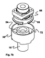
図5a,5bの実施形態と結合されることが可能であるシュラウドの別の実施形態によれば、シュラウド16をバルブに一時的に固定するための手段がシュラウドに設けられ、前記手段が図7a〜7dに示される。こうした手段により、バルブが開放され液体が鋳造される際にシュラウド16をバルブに一時的に固定し、このことにより、操作装置によって使用されるエネルギを減少させることができる。この例では、一時的な固定は、バイオネット嵌合による固定作用である。
According to another embodiment of the shroud that can be combined with the embodiment of FIGS. 5a, 5b, means are provided on the shroud for temporarily securing the
この手段は、一方では、バルブ14、より正確には鋳造ノズル18と、他方では、シュラウド16の端部54と協働する要素66を具備する。この要素66は、この端部54で回転すると共にノズル18と協働して取り付けられるように配置される。さらに正確には、要素66は、シュラウド16のヘッド56cと協働するための手段であって、ヘッド56cのリム72を具備する手段を受け取りつつ協働するように構成された手段(例えばリム68)を具備する。この要素はさらに、ノズル18と協働するための手段70であって、ノズル18のリム74と当接することによって協働する手段70を具備する。
This means comprises on the one hand a
バルブ14へのシュラウド16の一時的な固定作用は以下のように行われる。要素66は、まず第1に、留め具70,74を協働させることによってバルブ14に固定される。次いで、ヘッド56cが設けられたシュラウド16が要素66と一直線に取り付けられ、ヘッド56cは、リム68がヘッドのリム72と一直線にならずそれによりヘッド56cの底部に挿入されることが可能となるように配向される。リム68がヘッド56c入った時点で、ヘッド56cの回転、例えば1/4回転である回転が実施され、それにより、ヘッドのリム72が要素66のリム68を覆い、ひいてはシュラウド16がこのリム68によって保持される。当然ながら、反対方向の回転を実施することによってこのバイオネット嵌合の効力をなくし、リム68,72同士を開放することができる。
The temporary fixing operation of the
図3及び図3a〜3cは、図2及び図2a〜図2d以外の実施形態による操作装置を示す。しかしながら、この装置は比較的似ており、差異点のみを以下に記載する。 3 and 3a to 3c show an operating device according to an embodiment other than that of FIGS. 2 and 2a to 2d. However, this device is relatively similar and only the differences are described below.
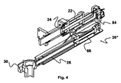
この操作装置26’は、図2の装置のシリンダ32を提供する必要がないので特に小型である。これは、この実施形態では、装置26’を駆動手段20に固定するための手段はシリンダ22を包囲すると共にロッド24に固定された部品80を具備し、それにより、ピストンがシリンダ22内を摺動するときにこの部品80がロッドと共に変位されるからである。さらに、保持アーム28は、部品80の両側で支持されている横アーム82によって側方で取り上げられている。モータ36’は、2つのアーム82同士の間に配置される。
This operating device 26 'is particularly small since it is not necessary to provide the
この実施形態の作用の形式は図2のものと似ており、軸体38,48,46,50は、前述において画定された鋳造位置、待機位置及び付与位置に到達するために、変形されることのできる平行四辺形を形成する。さらに正確には、図3aはバルブが閉鎖されている鋳造位置にある装置を示し、図3bは付与位置にある装置を示し、図3cは安全位置にある装置を示す。
The mode of action of this embodiment is similar to that of FIG. 2, and the
図4の装置は、操作装置26”の第3の実施形態に対応する。この装置はさらに、ロッド24と共に変位されるシリンダ22を包囲する部品を具備する。したがって、装置はまた小型である。この装置では、保持手段28,30を駆動するための手段は、モータ36などのロータリモータを具備せずにむしろ、図4に極めて簡略に示されている2つの液圧ジャッキ84,86を具備する。液圧ジャッキ84はほぼ鉛直であり、液圧ジャッキ86はほぼ水平である。この実施形態では、駆動手段は、4つの配向の軸体から構成される平行四辺形を具備していない。保持手段28の移動は、(示されていない手段によって)ジャッキ84、86の同期作用及び枢動接続部88,90によって制御される。さらに正確には、鉛直ジャッキ84により、鉛直方向に枢動軸体88を変位させることが可能になり、ジャッキ86により、アーム28に入れ子式に摺動させることが可能になる。
The device of Fig. 4 corresponds to a third embodiment of the operating
装置26”の作用の形式は、図4a〜図4dに記載される。図4aでは、装置は、アーム28がジャッキ86により延ばされている鋳造位置にある。図4bでは、ジャッキ84は、ジャッキ86を傾斜させ、ひいてはアーム28の端部30が下になるように軸体88上で押し、装置は次いで付与位置になる。図4cでは、装置はさらに付与位置になるが、アーム28は、ジャッキ86内で摺動することによって短くされる。図4dでは、装置は、アーム28がジャッキ86により短くされると共にジャッキ84により引き上げられた、安全位置にある。
The mode of action of the
他の実施形態と同様に、保持アーム28の端部30がU字形状の軌跡を有することが理解できる。
As with the other embodiments, it can be seen that the
図6及び図6a〜図6dは、バルブ14のための駆動装置100を示す。この駆動装置100は、上述の駆動手段20と同様でもよいし、又は全く異なるものを使用してもよい。
6 and 6a to 6d show the
装置100は、ロッド24同様の剛性ロッド106に接続された第1のピストン104が備えられたシリンダ102を具備し、剛性ロッド106は、その端部108によりバルブ14を制御する。ピストン104は、図6bで見ることができると共に供給管114,116を通して流体を供給することができる2つの液圧チャンバ110,112の範囲をシリンダ102によって定める。
The
駆動装置100は、鋳造取瓶12に、さらに正確には鋳造取瓶に設けられたハウジング118に、あるいはバルブ14に固定されるよう構成される。バルブ14に対する装置100のこの固定作用を実施するために、装置100は、ハウジング118の壁122に押圧するように配置された第2のピストン120を具備し、ハウジング118内で締め付け作用によって駆動装置100をロックする。さらに正確には、第2のピストン102は、駆動装置100、さらに正確にはシリンダ102と、ハウジング118の壁122との間で楔を形成するように構成される。ピストン120及び壁122は、ピストン104によって制御されるロッド106によって貫通され、このロッドが第1のピストン104の変位の影響を受けて摺動することができる。
The
図6bで理解できるように、チャンバ112は、一方では第1のピストン104によって、他方では第2のピストン120によって範囲が定められる。
As can be seen in FIG. 6b, the
これより、装置100の作用の形式が記載される。駆動装置100は、ハウジング118に取り付けられる前において、ほぼ図6dに図示された構成を有する。第2のピストン120は、チャンバ112内に引っ込められた位置にあり、シリンダ102から全く又は非常にわずかだけ突出し、その結果、シリンダ102の長さは比較的に短い。シリンダ102の長さが短くなるので、間隙124によりハウジング118内部にシリンダ102を挿入することが容易にできる。ハウジング118内にシリンダ102をロックするために、図6aで参照番号126によって示されている矢印の方向に向かって、流体が孔116内部に注入される。流体の注入は、ピストン120を壁122に向かって摺動させ、その結果、ピストン120は、シリンダ102の端まで変位され、壁122に係止する。したがって、ハウジング118とシリンダ102との間の間隙124がなくなり、装置100は、締め付け作用によってロックされる。
From this, the mode of action of the
この固定作用に続いて、駆動装置100は、図6b及び図6cで示されるように、バルブ14を駆動する働きをすることができる。バルブ14に係止する力を及ぼすために、流体は、管114を通して注入され、それにより、図6bに示されているように、右向きに第1のピストン104、ひいてはロッド106、ひいてはバルブの対応するゲートを変位させるという効果を有する。さらに、管116内部に流体を注入することによって、図6cに示されているように、反対方向に、つまり左に向かって第1のピストン104を変位させることができる。
Following this locking action, the
バルブ14の操作が終了すると、以下のような手順によって、ハウジング118から駆動装置100を解放することができる。第1のピストン104が中立位置にあるときに、圧力は、ピストン120を壁122に押圧されるように、図6dの矢印128の方向にシリンダ102の後部に対して印加され、それにより、ピストン120をチャンバ112内部で摺動させる。結果として、シリンダ102の長さが減少し、間隙124が再び現れ、それにより、ハウジング118から装置を容易に取り外すことができる。
When the operation of the
ピストンをロックすることを妨げることを可能にするスプリング(弾性)ワッシャ123を提供することもできる。
It is also possible to provide a spring (elastic)
上述の作用の形式が特に、自動化されたやり方で実施されるのに適したものであることが理解される。これは、締め付け作用によってロックする前に間隙124が存在することができるという理由から、ロボットによってハウジング118内に駆動装置100を配置することが容易にできるからである。
It will be appreciated that the mode of action described above is particularly suitable for being implemented in an automated manner. This is because the
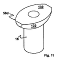
さらに、図8〜図11は、把持ヘッド56d及び縦方向軸線134を有する取瓶シュラウド16を示す。把持ヘッドは、上方表面130及び下方表面132を有する。把持ヘッド56dの下方部分が紡錘形であることが、図11により容易に理解することができる。
Further, FIGS. 8-11 show the
図12は、把持ヘッド56eが半円筒形である別の取瓶シュラウドを示す。
FIG. 12 shows another bin shroud in which the
図13は、図8〜図11のシュラウドの金属シースを示す。シースには、この場合では翼部58である角度配向手段(そのうちの1つが図面で見ることができ、その他はシュラウドの反対側に配置される。)と、2つの凹部136であって、各凹部が側壁138a,138b及び底壁140を具備する、2つの凹部(同一のハウジングがシュラウドの反対側に配置されている。)とが設けられている。この凹部は、操作装置の指状部63と協働して、
− シュラウドの下方端部がスチールの浴槽に浸されるときに、シュラウドが上昇することが妨げられ(指状部63が凹部136の底壁140に対して作用する。)、
− 鋳造作用の終わりにおいて、シュラウドを取り外すことができ(指状部63が、凹部136の底壁140に対して作用する。)、かつ、
− 取瓶シュラウドがその支持体に保持されることを保証する(指状部が凹部136の側壁138a,138bに対して作用する。)。
FIG. 13 shows the metal sheath of the shroud of FIGS. The sheath includes an angular orientation means, in this case wings 58 (one of which can be seen in the drawing, the other being arranged on the opposite side of the shroud) and two
When the lower end of the shroud is immersed in a steel bath, the shroud is prevented from rising (the
At the end of the casting operation, the shroud can be removed (the
Ensuring that the bin shroud is held on its support (the fingers act on the
本発明の利点が上述されてきた。本発明が上述の実施形態に制限されないことが理解されるであろう。 The advantages of the present invention have been described above. It will be understood that the present invention is not limited to the embodiments described above.
具体的には、様々な操作装置及び駆動装置において、又はシュラウドにおいて、様々な機能性を独立して確認することができ、あるいは、様々な機能性を互いに組み合わせることができる。 In particular, various functionalities can be independently confirmed in various operating devices and drive devices, or in a shroud, or various functionalities can be combined with each other.
Claims (20)
縦方向軸線(134)を有し、かつ、
1つの端部にシュラウド把持ヘッド(56d、56e)を具備する、
取瓶シュラウドにおいて、
把持ヘッド(56d、56e)の下方端部が半球形状ではない紡錘状である、
取瓶シュラウド。 A bin shroud (16) for the flow of liquid metal from a casting bin to a metal tundish,
Having a longitudinal axis (134), and
A shroud gripping head (56d, 56e) at one end;
In the intake shroud,
The lower end of the gripping head (56d, 56e) has a spindle shape that is not hemispherical ,
Tray shroud.
請求項1に記載の取瓶シュラウド(16)。 Comprising a semi-cylindrical gripping head (56e);
A bottle shroud (16) according to claim 1 .
請求項1に記載の取瓶シュラウド(16)。 Comprising a gripping head (56d) in the form of a curved spindle;
A bottle shroud (16) according to claim 1 .
請求項1〜3のいずれか1項に記載の取瓶シュラウド。 And further comprises means (58) for angular orientation of the shroud (16) about the vertical axis of the shroud.
The bottle shroud according to any one of claims 1 to 3 .
請求項1〜4のいずれか1項に記載の取瓶シュラウド。 Comprising release means (62) for shroud from the casting hole (18) formed in the upper end (54) of the shroud;
The bottle shroud according to any one of claims 1 to 4 .
各凹部が側壁(138a,138b)および底壁(140)を具備する、
請求項5に記載の取瓶シュラウド。 The gripping head (56a, 56b, 56c, 56d, 56e) comprises a side wall provided with two recesses (136);
Each recess comprises a side wall (138a, 138b) and a bottom wall (140).
The bottle shroud according to claim 5 .
液体金属を鋳造するためのシュラウド(16)のための操作装置(26,26’,26”)であって、
液体金属のための流れ制御バルブ(14)の下流にシュラウドのための保持手段(28,30,30’)を具備し、
このバルブが、駆動手段(20)の動作によって開放構成及び閉鎖構成を取ることができる、
操作装置において、
バルブのための駆動手段(20)への固定手段(32,34,80)を具備する、
操作装置と、
からなる組立体。 The bottle shroud (16) according to any one of claims 1 to 6 ,
An operating device (26, 26 ', 26 ") for a shroud (16) for casting liquid metal ,
Holding means (28, 30, 30 ') for the shroud downstream of the flow control valve (14) for the liquid metal;
The valve can take an open configuration and a closed configuration by operation of the drive means (20).
In the operating device,
Comprising fixing means (32, 34, 80) to driving means (20) for the valve;
An operating device;
An assembly consisting of
請求項7に記載の組立体。 The assembly according to claim 7.
請求項7又は8に記載の組立体。 The assembly according to claim 7 or 8.
請求項9に記載の組立体。 The assembly according to claim 9.
請求項9に記載の組立体。 The assembly according to claim 9.
保持手段(28,30,30’)のための駆動手段(36〜50,84,86)が、シリンダ(22)を包囲する部品(80,80’)によって支持されると共にロッド(24)と共に変位される、 Drive means (36-50, 84, 86) for the holding means (28, 30, 30 ') are supported by the parts (80, 80') surrounding the cylinder (22) and with the rod (24). Displaced,
請求項9〜11のいずれか1項に記載の組立体。 The assembly according to any one of claims 9 to 11.
請求項7〜12のいずれか1項に記載の組立体。 The assembly according to any one of claims 7 to 12.
請求項7〜13のいずれか1項に記載の組立体。 The assembly according to any one of claims 7 to 13.
請求項7〜14のいずれか1項に記載の組立体。 The assembly according to any one of claims 7 to 14.
開放構成と閉鎖構成との間でバルブを変位させることができる第1のピストン(104)をシリンダ(102)内に具備する、
駆動装置において、
バルブ(14)に対して駆動装置(100)を固定するための第2のピストン(120)をシリンダ(102)内に具備し、
2つの液圧チャンバ(110,112)を具備し、これらチャンバのうちの1つは、一方では第1の液圧ピストン(104)によって範囲を定められ、他方では第2の液圧ピストン(120)によって範囲を定められる、
駆動装置。 A drive (100) for a flow control valve (14) for casting liquid metal comprising:
Comprising in the cylinder (102) a first piston (104) capable of displacing the valve between an open configuration and a closed configuration;
In the drive device,
A second piston (120) for fixing the drive device (100) to the valve (14) is provided in the cylinder (102) ;
Two hydraulic chambers (110, 112) are provided, one of which is delimited on the one hand by the first hydraulic piston (104) and on the other hand the second hydraulic piston (120). )
Drive device.
請求項16に記載の駆動装置。 The second piston (120) is intended to be received in a housing (118) fixed to the valve (14), so that the drive (110) is locked in the housing (118) by a clamping action. Arranged to press the wall (122) of the housing,
The drive device according to claim 16 .
請求項17に記載の駆動装置。 The piston head and the opposing face of the second piston (120) intended to form a wedge between the drive device (100) and the housing wall (122) after displacement of the second piston (120) Having an end to
The drive device according to claim 17 .
請求項16〜18のいずれか1項に記載の駆動装置。 The second piston (120) is pierced by a rigid rod (24) controlled by the first piston (104),
The drive device according to any one of claims 16 to 18 .
請求項16〜19のいずれか1項に記載の駆動装置。 An elastic washer (123) is disposed around the rod (24, 106) under the head of the first piston (104).
The drive device according to any one of claims 16 to 19 .
Applications Claiming Priority (5)
| Application Number | Priority Date | Filing Date | Title |
|---|---|---|---|
| EP08169518.1 | 2008-11-20 | ||
| EP08169518 | 2008-11-20 | ||
| EP09008451A EP2301693A1 (en) | 2009-06-29 | 2009-06-29 | Shroud nozzle |
| EP09008451.8 | 2009-06-29 | ||
| PCT/EP2009/008244 WO2010057640A1 (en) | 2008-11-20 | 2009-11-19 | Casting pipe, device for handling said pipe and valve driving device |
Publications (3)
| Publication Number | Publication Date |
|---|---|
| JP2012509186A JP2012509186A (en) | 2012-04-19 |
| JP2012509186A5 JP2012509186A5 (en) | 2012-11-01 |
| JP5405583B2 true JP5405583B2 (en) | 2014-02-05 |
Family
ID=41506557
Family Applications (1)
| Application Number | Title | Priority Date | Filing Date |
|---|---|---|---|
| JP2011536776A Expired - Fee Related JP5405583B2 (en) | 2008-11-20 | 2009-11-19 | Casting shroud, operating device for the shroud and device for driving a valve |
Country Status (20)
| Country | Link |
|---|---|
| US (1) | US8926893B2 (en) |
| EP (1) | EP2367651B1 (en) |
| JP (1) | JP5405583B2 (en) |
| KR (1) | KR101678705B1 (en) |
| CN (1) | CN102281972B (en) |
| AU (1) | AU2009317593B2 (en) |
| BR (1) | BRPI0922101B1 (en) |
| CA (1) | CA2743091A1 (en) |
| DK (1) | DK2367651T3 (en) |
| ES (1) | ES2402083T3 (en) |
| MX (1) | MX2011005337A (en) |
| MY (1) | MY156901A (en) |
| NZ (1) | NZ593480A (en) |
| PL (1) | PL2367651T3 (en) |
| PT (1) | PT2367651E (en) |
| RS (1) | RS52687B (en) |
| RU (1) | RU2511162C2 (en) |
| SI (1) | SI2367651T1 (en) |
| WO (1) | WO2010057640A1 (en) |
| ZA (1) | ZA201104535B (en) |
Families Citing this family (8)
| Publication number | Priority date | Publication date | Assignee | Title |
|---|---|---|---|---|
| AU2014336310B2 (en) * | 2013-10-14 | 2018-05-17 | Vesuvius Group (Sa) | Coupling device for reversibly coupling a ladle shroud to a collector nozzle, self-supported ladle shroud, kit thereof and method for coupling a ladle shroud to a collector nozzle |
| AR099467A1 (en) * | 2014-02-19 | 2016-07-27 | Vesuvius Group Sa | COAT SPOON COAT FOR METAL COAT, COUPLING ASSEMBLY SET TO COUPLING SUCH COVER SPOON COVERING TO A SPOON, METAL COATING INSTALLATION AND COUPLING PROCESS |
| AT516885B1 (en) * | 2015-02-23 | 2017-12-15 | Primetals Technologies Austria GmbH | Casting device with holder of a shadow tube on the pan closure |
| CN106493346B (en) * | 2016-12-12 | 2019-09-13 | 华耐国际(宜兴)高级陶瓷有限公司 | A kind of immersion water gap for continuously casting |
| CN106513656B (en) * | 2017-01-12 | 2019-04-16 | 中冶赛迪工程技术股份有限公司 | Hydraulic control circuit and its method for the rotation of conticaster long nozzle clamping device |
| EP3424618B1 (en) | 2017-07-05 | 2021-03-10 | Refractory Intellectual Property GmbH & Co. KG | Sliding closure for a vessel containing molten metal |
| CN108326275B (en) * | 2018-02-08 | 2020-02-14 | 湖南镭目科技有限公司 | Automatic long nozzle dismounting device |
| WO2021198305A1 (en) * | 2020-03-31 | 2021-10-07 | Vesuvius Group, S.A. | Robotized ladle transportation device system with embedded manipulator |
Family Cites Families (15)
| Publication number | Priority date | Publication date | Assignee | Title |
|---|---|---|---|---|
| US4316561A (en) * | 1980-08-05 | 1982-02-23 | United States Steel Corporation | Pour tube latching apparatus |
| JPS57115968A (en) * | 1981-01-08 | 1982-07-19 | Nisshin Steel Co Ltd | Method and means for cleaning of teeming nozzle hole with oxygen |
| US4892235A (en) * | 1988-06-23 | 1990-01-09 | Flo-Con Systems, Inc. | Joint and shroud support for pour tube and collector nozzle |
| EP0577909A1 (en) * | 1992-07-10 | 1994-01-12 | FLOCON ITALIANA S.r.l. | Replaceable auxiliary nozzle |
| FR2694711B1 (en) * | 1992-08-14 | 1994-11-10 | Daussan & Co | Positioning device for pouring tube. |
| JP3420263B2 (en) * | 1992-09-02 | 2003-06-23 | 黒崎播磨株式会社 | Nozzle support structure for continuous casting |
| FR2733705B1 (en) | 1995-05-05 | 1997-06-13 | Vesuvius France Sa | DEVICE AND METHOD FOR CHANGING A CONTINUOUS CASTING TUBE OF A STEEL DISTRIBUTOR |
| FR2741555B1 (en) * | 1995-11-23 | 1997-12-26 | Usinor Sacilor | NOZZLE FOR THE INTRODUCTION OF A LIQUID METAL INTO A CONTINUOUS CASTING LINGOT OF METAL PRODUCTS, AND CONTINUOUS CASTING INSTALLATION OF METAL PRODUCTS EQUIPPED WITH SUCH A NOZZLE |
| JP3168157B2 (en) | 1996-01-23 | 2001-05-21 | 住友重機械工業株式会社 | Long nozzle attachment / detachment device for continuous casting machine |
| JP3741992B2 (en) * | 2001-10-15 | 2006-02-01 | 品川白煉瓦株式会社 | Nozzle structure for continuous casting |
| KR100916101B1 (en) * | 2002-09-06 | 2009-09-11 | 주식회사 포스코 | An apparatus for automatically connecting shroud nozzle to collector nozzle |
| AT502058B1 (en) * | 2005-06-20 | 2007-11-15 | Voest Alpine Ind Anlagen | CONTINUITY CASTING SYSTEM WITH AT LEAST ONE MULTIFUNCTION ROBOT |
| US7628952B2 (en) * | 2007-04-05 | 2009-12-08 | Sms Demag, Inc. | Method and apparatus for testing the integrity of a shroud seal on a ladle for a continuous casting installation |
| PT2367648E (en) * | 2008-11-20 | 2013-04-04 | Vesuvius Group Sa | Ladle pipe for liquid metal casting plant |
| US9199306B2 (en) * | 2008-11-20 | 2015-12-01 | Vesuvius Crucible Company | Support head for handling a ladle shroud |
-
2009
- 2009-11-19 DK DK09763841.5T patent/DK2367651T3/en active
- 2009-11-19 BR BRPI0922101A patent/BRPI0922101B1/en not_active IP Right Cessation
- 2009-11-19 KR KR1020117014170A patent/KR101678705B1/en active IP Right Grant
- 2009-11-19 EP EP09763841A patent/EP2367651B1/en active Active
- 2009-11-19 SI SI200930491T patent/SI2367651T1/en unknown
- 2009-11-19 PL PL09763841T patent/PL2367651T3/en unknown
- 2009-11-19 RS RS20130084A patent/RS52687B/en unknown
- 2009-11-19 JP JP2011536776A patent/JP5405583B2/en not_active Expired - Fee Related
- 2009-11-19 PT PT97638415T patent/PT2367651E/en unknown
- 2009-11-19 MX MX2011005337A patent/MX2011005337A/en active IP Right Grant
- 2009-11-19 ES ES09763841T patent/ES2402083T3/en active Active
- 2009-11-19 US US13/130,460 patent/US8926893B2/en not_active Expired - Fee Related
- 2009-11-19 AU AU2009317593A patent/AU2009317593B2/en not_active Ceased
- 2009-11-19 WO PCT/EP2009/008244 patent/WO2010057640A1/en active Application Filing
- 2009-11-19 RU RU2011124592/02A patent/RU2511162C2/en not_active IP Right Cessation
- 2009-11-19 NZ NZ593480A patent/NZ593480A/en not_active IP Right Cessation
- 2009-11-19 MY MYPI2011002112A patent/MY156901A/en unknown
- 2009-11-19 CN CN200980155160.0A patent/CN102281972B/en not_active Expired - Fee Related
- 2009-11-19 CA CA2743091A patent/CA2743091A1/en not_active Abandoned
-
2011
- 2011-06-20 ZA ZA2011/04535A patent/ZA201104535B/en unknown
Also Published As
| Publication number | Publication date |
|---|---|
| KR20110095382A (en) | 2011-08-24 |
| CA2743091A1 (en) | 2010-05-27 |
| CN102281972A (en) | 2011-12-14 |
| EP2367651A1 (en) | 2011-09-28 |
| US20110278331A1 (en) | 2011-11-17 |
| PT2367651E (en) | 2013-04-04 |
| AU2009317593B2 (en) | 2014-05-08 |
| ES2402083T3 (en) | 2013-04-26 |
| SI2367651T1 (en) | 2013-03-29 |
| ZA201104535B (en) | 2012-09-26 |
| KR101678705B1 (en) | 2016-11-23 |
| RU2011124592A (en) | 2012-12-27 |
| PL2367651T3 (en) | 2013-05-31 |
| BRPI0922101B1 (en) | 2017-03-28 |
| MY156901A (en) | 2016-04-15 |
| US8926893B2 (en) | 2015-01-06 |
| DK2367651T3 (en) | 2013-04-02 |
| CN102281972B (en) | 2014-12-24 |
| MX2011005337A (en) | 2011-06-16 |
| RS52687B (en) | 2013-08-30 |
| JP2012509186A (en) | 2012-04-19 |
| EP2367651B1 (en) | 2013-01-02 |
| RU2511162C2 (en) | 2014-04-10 |
| NZ593480A (en) | 2013-02-22 |
| WO2010057640A1 (en) | 2010-05-27 |
| AU2009317593A1 (en) | 2011-07-07 |
| BRPI0922101A2 (en) | 2016-02-10 |
Similar Documents
| Publication | Publication Date | Title |
|---|---|---|
| JP5405583B2 (en) | Casting shroud, operating device for the shroud and device for driving a valve | |
| RU2524035C2 (en) | Bearing head for liquid metal teeming ladle pipe support | |
| JP2012509186A5 (en) | ||
| US8376196B2 (en) | Apparatus for the interchangeable connection of a casting tube to a spout of a melt vessel | |
| CN101786158A (en) | Quick change device for stopper rod | |
| JP7291133B2 (en) | Bottom plate assembly with collector nozzle without bayonet | |
| KR20090123594A (en) | Long nozzle support apparatus | |
| US7958928B2 (en) | Method and apparatus for casting metal articles | |
| ES2428016T3 (en) | Device for installation and removal of a porous plug | |
| CN110961897B (en) | Bolt dismounting device | |
| JP7482877B2 (en) | Robotized system for replacing sliding gate valve plates | |
| CN111571458A (en) | Hanging bracket for shot blasting of brake drum casting | |
| KR101063905B1 (en) | Desorption System and Desorption System of Ladle Cover Using the Same | |
| CN219744797U (en) | Catalyst preparation is with sediment device | |
| CN110479961A (en) | A kind of technique of titanium alloy combination casting | |
| CN212609157U (en) | Detachable plays gallows | |
| JP5725853B2 (en) | Connecting rod bearing metal exchanging device and exchanging method thereof, piston support jig | |
| JPH0648943U (en) | Tundish tuyere brick cleaning equipment | |
| JP2562783B2 (en) | Automatic water heater for molten metal | |
| JPH0428688Y2 (en) | ||
| CA3227256A1 (en) | Mould for casting molten metal comprising a coupling mechanism for a shroud, casting installation for casting a molten metal and method for casting a molten metal | |
| JPH07227662A (en) | Device for supplying molten magnesium | |
| JPH08136782A (en) | Mechanism for automatic attachment, detachment and fixing of device | |
| GB2538656A (en) | Shroud tube manipulator | |
| JPH08290262A (en) | Lower nozzle removing device of molten metal storing container |
Legal Events
| Date | Code | Title | Description |
|---|---|---|---|
| A521 | Written amendment |
Free format text: JAPANESE INTERMEDIATE CODE: A523 Effective date: 20120904 |
|
| A621 | Written request for application examination |
Free format text: JAPANESE INTERMEDIATE CODE: A621 Effective date: 20120904 |
|
| A977 | Report on retrieval |
Free format text: JAPANESE INTERMEDIATE CODE: A971007 Effective date: 20130306 |
|
| A131 | Notification of reasons for refusal |
Free format text: JAPANESE INTERMEDIATE CODE: A131 Effective date: 20130312 |
|
| A521 | Written amendment |
Free format text: JAPANESE INTERMEDIATE CODE: A523 Effective date: 20130612 |
|
| A01 | Written decision to grant a patent or to grant a registration (utility model) |
Free format text: JAPANESE INTERMEDIATE CODE: A01 Effective date: 20131001 |
|
| A61 | First payment of annual fees (during grant procedure) |
Free format text: JAPANESE INTERMEDIATE CODE: A61 Effective date: 20131030 |
|
| R250 | Receipt of annual fees |
Free format text: JAPANESE INTERMEDIATE CODE: R250 |
|
| LAPS | Cancellation because of no payment of annual fees |