JP5399413B2 - Flangeless magnetic flow meter with integrated retaining ring, valve seat, and liner protector - Google Patents
Flangeless magnetic flow meter with integrated retaining ring, valve seat, and liner protector Download PDFInfo
- Publication number
- JP5399413B2 JP5399413B2 JP2010544325A JP2010544325A JP5399413B2 JP 5399413 B2 JP5399413 B2 JP 5399413B2 JP 2010544325 A JP2010544325 A JP 2010544325A JP 2010544325 A JP2010544325 A JP 2010544325A JP 5399413 B2 JP5399413 B2 JP 5399413B2
- Authority
- JP
- Japan
- Prior art keywords
- liner
- magnetic
- flangeless
- pipe portion
- flow meter
- Prior art date
- Legal status (The legal status is an assumption and is not a legal conclusion. Google has not performed a legal analysis and makes no representation as to the accuracy of the status listed.)
- Expired - Fee Related
Links
Images


Classifications
-
- G—PHYSICS
- G01—MEASURING; TESTING
- G01F—MEASURING VOLUME, VOLUME FLOW, MASS FLOW OR LIQUID LEVEL; METERING BY VOLUME
- G01F1/00—Measuring the volume flow or mass flow of fluid or fluent solid material wherein the fluid passes through a meter in a continuous flow
- G01F1/56—Measuring the volume flow or mass flow of fluid or fluent solid material wherein the fluid passes through a meter in a continuous flow by using electric or magnetic effects
- G01F1/58—Measuring the volume flow or mass flow of fluid or fluent solid material wherein the fluid passes through a meter in a continuous flow by using electric or magnetic effects by electromagnetic flowmeters
- G01F1/588—Measuring the volume flow or mass flow of fluid or fluent solid material wherein the fluid passes through a meter in a continuous flow by using electric or magnetic effects by electromagnetic flowmeters combined constructions of electrodes, coils or magnetic circuits, accessories therefor
-
- G—PHYSICS
- G01—MEASURING; TESTING
- G01F—MEASURING VOLUME, VOLUME FLOW, MASS FLOW OR LIQUID LEVEL; METERING BY VOLUME
- G01F15/00—Details of, or accessories for, apparatus of groups G01F1/00 - G01F13/00 insofar as such details or appliances are not adapted to particular types of such apparatus
- G01F15/18—Supports or connecting means for meters
- G01F15/185—Connecting means, e.g. bypass conduits
Description
本発明は、概して、プロセスの測定および制御のためのフィールドデバイスに関する。具体的には、本発明は、フランジレスのプロセスカップリングおよび統合型ライナー保護部を備える磁気式流量計に関する。 The present invention relates generally to field devices for process measurement and control. Specifically, the present invention relates to a magnetic flow meter with a flangeless process coupling and an integrated liner protector.
フィールドデバイスは、圧力、温度、流速等のプロセスパラメータを測定および制御するように設計された広範囲のプロセス管理デバイスを含む。これらのデバイスは、製造、炭化水素処理、水圧破砕および他の液体炭化水素抽出技法、バルク流体取扱、食品および飲料加工、水および空気の分配、環境制御、ならびに接着剤、樹脂、薄膜および熱可塑性物質の精密製造の用途を含む、多様な業界における広範な有用性を有する。 Field devices include a wide range of process management devices designed to measure and control process parameters such as pressure, temperature, flow rate and the like. These devices include manufacturing, hydrocarbon processing, hydraulic fracturing and other liquid hydrocarbon extraction techniques, bulk fluid handling, food and beverage processing, water and air distribution, environmental control, and adhesives, resins, thin films and thermoplastics Has broad utility in diverse industries, including precision manufacturing applications of materials.
フィールドデバイスは、プロセスパラメータを測定または検知するように構成される、トランスミッタ、および目標値を達成するために、このようなパラメータを変更または制御するように構成される、コントローラを含む。センサモジュールは、また、温度センサ、圧力変換器、PHセンサ、レベルセンサ、ならびに、追加のプロセス変数およびプロセス流体パラメータを特性化するための様々な他のデバイスを含む。より汎用化されたフィールドデバイスは、圧力/温度トランスミッタ等のマルチセンサトランスミッタ、ならびにセンサおよび制御機能の両方を備える統合型コントローラを含む。これらの汎用デバイスは、いくつかの関連するプロセス圧力、温度、流体レベルおよび流速を測定および調節する、統合型流量制御装置および静圧タンク計測システムを含む。 The field device includes a transmitter configured to measure or sense process parameters and a controller configured to change or control such parameters to achieve a target value. The sensor module also includes a temperature sensor, a pressure transducer, a PH sensor, a level sensor, and various other devices for characterizing additional process variables and process fluid parameters. More generalized field devices include multi-sensor transmitters such as pressure / temperature transmitters and integrated controllers with both sensor and control functions. These general purpose devices include integrated flow controllers and hydrostatic tank measurement systems that measure and adjust several associated process pressures, temperatures, fluid levels and flow rates.
流量計および関連するトランスミッタは、流体処理において特に重要な役割を果たし、多種多様な技術を採用する。これらとしては、流量を機械的回転の関数として特性化するタービン流量計、流量を圧力の関数として特性化する差圧センサ、流量を熱伝導の関数として特性化する質量流量計、および流量を振動効果の関数として特性化する渦流量計またはコリオリ流量計が挙げられるが、これらに限定されない。 Flow meters and associated transmitters play a particularly important role in fluid processing and employ a wide variety of technologies. These include turbine flow meters that characterize flow as a function of mechanical rotation, differential pressure sensors that characterize flow as a function of pressure, mass flow meters that characterize flow as a function of heat, and vibrations of flow. Examples include, but are not limited to, vortex flowmeters or Coriolis flowmeters that characterize as a function of effect.
磁気式流量計は、機械的または熱力学的効果ではなく電磁相互作用に基づく、ファラデーの法則から流量を特性化するという点で、他の流量測定技術から区別される。特に、磁気式流量計は、イオンを含有する水等のプロセス液体の伝導性、および磁場領域を通って流れると流体にわたって誘発される起電力に依存する。 Magnetic flow meters are distinguished from other flow measurement techniques in that they characterize the flow rate from Faraday's law, which is based on electromagnetic interactions rather than mechanical or thermodynamic effects. In particular, magnetic flow meters rely on the conductivity of process liquids, such as water containing ions, and the electromotive force induced across the fluid as it flows through the magnetic field region.
磁気式流量計は、「ダーティ」な(侵食性および腐食性の)流体用途において、または、機械的および流れに抵抗をもたらす技術が許容できない圧力低下を発生させる流量条件下において、顕著な利点を提供する。しかしながら、磁気式流量計は、電磁誘導に依存しているため、いくつかの工学設計課題も提示する。これらとしては、電気を絶縁する保護ライナーおよび特殊なフランジカップリング金具に対する必要性が挙げられ、これは、コストを増加させ、耐用年数を減少させる。このように、改善された磁気式流量計の設計が依然として必要とされる。特に、設置時間および保守要件を削減できる改善されたプロセスカップリング構造、ならびに耐用年数を増加できるより耐久性のあるライナー設計に対する必要が存在する。 Magnetic flow meters offer significant advantages in "dirty" (erosive and corrosive) fluid applications or under flow conditions where mechanical and flow resistance techniques produce unacceptable pressure drops. provide. However, magnetic flow meters rely on electromagnetic induction and therefore present some engineering design challenges. These include the need for protective liners and special flange coupling fittings that insulate electricity, which increases costs and reduces service life. Thus, there is still a need for improved magnetic flow meter designs. In particular, there is a need for improved process coupling structures that can reduce installation time and maintenance requirements, and more durable liner designs that can increase service life.
本発明は、フランジレス磁気式流量計の本体に関する。流量計の本体は、パイプ部分、ライナー、保持環およびライナー保護部を備える。パイプ部分は、流量計の本体を通じて延在し、ライナーは、パイプ部分の内側を被覆して、絶縁されたプロセス流路を形成する。保持環は、プロセス流路への終端間流体接続を形成するために、パイプ部分の終端上に配置される。ライナー保護部は、保持環上に形成され、絶縁ライナーのために終端密閉部を提供する。 The present invention relates to a main body of a flangeless magnetic flow meter. The main body of the flow meter includes a pipe portion, a liner, a retaining ring, and a liner protector. The pipe portion extends through the body of the flow meter and the liner covers the inside of the pipe portion to form an insulated process flow path. A retaining ring is disposed on the end of the pipe portion to form an end-to-end fluid connection to the process flow path. The liner protector is formed on the retaining ring and provides a terminal seal for the insulating liner.
図1は、統合型トランスミッタ11およびフランジレスプロセスカップリング12とを装備した磁気式流量計の側面模式図である。磁気式流量計10は、流量計本体13と、フランジレスプロセスカップリング12を経由してプロセス流に結合する、パイプ部分14と、を備える。トランスミッタ11は、端子ブロック22と、電子/LOI(ローカルオペレータインターフェース)組立部23(どちらも隠れ線で図示)と、を備える筐体組立部21を備える。
FIG. 1 is a schematic side view of a magnetic flow meter equipped with an integrated
流量計本体(または測定器本体)13は、鋼、アルミニウムもしくは適切な金属合金、またはPVC(塩化ポリビニル)またはABS(アクリロニトリル・ブタジエン・スチレン)プラスチック等の耐久性ポリマー等、機械的強度を備える耐久性材料から形成される。流量計本体13は、軸中心線CLに沿ってパイプ部分14の周囲に同軸上に配向され、コイル15およびプローブ16の周囲に概して円筒形の筐体を形成する。
The flow meter body (or measuring device body) 13 is durable with mechanical strength such as steel, aluminum or a suitable metal alloy, or a durable polymer such as PVC (polyvinyl chloride) or ABS (acrylonitrile butadiene styrene) plastic. It is formed from a functional material. The
また、流量計本体13は、トランスミッタ11のトランスミッタ取付部17およびプローブ16を被覆するプローブカバー18も提供する。図1にはプローブカバー18は1つだけ示されていることに留意されたい。典型的には、プローブ16は、パイプ部分14の各側に1つの、2つのプローブ電極を備え、次の図2に示されるように各々専用のカバーを有する。
The
パイプ部分14は、鋼、ステンレス鋼、銅、アルミニウム、または金属合金等の耐久性のある、機械加工可能な材料から製造される。代替の実施形態において、パイプ部分14は、ABS、PVCまたは耐久性プラスチック等の耐久性ポリマー材料から形成される。
The
パイプ部分14(隠れ線で図示)は、磁気式流量計10を通るプロセス流Fにプロセス流路またはプロセス流導管を提供する。一実施形態において、パイプ部分14は、内径が約8インチ(8″または約20cm)である円形のパイプ部分を備える。他の実施形態において、パイプ部分14の直径は変動する。代替として、パイプ部分14は、楕円、矩形、または他の非円形の断面を有する。パイプ部分14には、図2および3を参照して以下に説明されるように、ライナーも提供される。
Pipe portion 14 (shown in hidden lines) provides a process flow path or process flow conduit for process flow F through
典型的な実施形態において、フランジレスプロセスカップリング12は、パイプ部分14と同一の材料(つまり、実質的に同一の組成である材料)から成る。代替の実施形態において、フランジレスプロセスカップリング12は、他の金属、他の金属合金、および他の耐久性ポリマー材料を含むが、これらに限定されない、他の材料から製造された追加の構成要素を利用する。
In an exemplary embodiment, the
プロセスカップリング12は、機械加工、溶接、および他の機械工程により、パイプ部分14に形成されたフランジレス構造である。このように、カップリング構造部12は、プロセス流路の終端上に配置され、磁気式流量計10と流体処理システムとの間に終端間または「直管」接続を形成する、フランジレス取付および保持要素を提供する。
The
フランジレスプロセスカップリング12、流量計本体13、およびパイプ部分14は、典型的に、非磁性材料から形成される。これによって、コイル15により生成される場の歪みを防止し、かつ、場が、比較的影響を受けずにパイプ部分14を横断することを可能にする。一部の実施形態において、流量計本体13は、パイプ部分14の外側に、磁気的に柔軟な磁束復元構成要素も備え、磁場の強度を増加させ、均一性を改善し、流量計10の外側の周縁磁場を減少する。
The flangeless process coupling 12, the
磁気式流量計10の操作において、イオン水溶液等の伝導性プロセス流体は、プロセス流路を経由してパイプ部分14を流過する。磁気コイル15は、パイプ部分の内側に磁場を生成し、伝導流にわたって(つまり、プローブ電極16およびプロセス流路にわたって)起電力(EMF、または電圧)を誘導する。誘導電圧は、流速と磁場強度の関数である。トランスミッタ11は、コイル15を作動させるために必要な電流を提供し、プロセス流速を測定またはそうでなければ判定するために、電極16からの電圧信号を処理する。
In the operation of the
トランスミッタ11の筐体組立部21は、金属または耐久性プラスチック等の耐久性材料、またはこのような材料の組み合わせから製造される。筐体組立部21は、端子ブロック22および電子/LOI組立部23を含む、内部のトランスミッタ構成要素を固定するように、内部のプロセスカップリングを備える。また、筐体組立部21は、内部のトランスミッタ構成要素も絶縁し、水分および腐食性または爆発性化学物質等の悪環境条件から遮断し、プロセス機械、ツール、落下物、ならびに他の潜在的な危険との接触から保護する。
The
一部の実施形態において、筐体組立部21は、筐体組立部21を密閉し、かつ端子ブロック22へのアクセス、ならびにいくつかの導管接続部25を提供するように、取り外し可能な筐体カバー(端子ブロックカバー)24を備える。これらの実施形態において、筐体組立部21は、典型的に、筐体組立部21を密閉し、かつ、電子/LOI組立部23への目視または機械的アクセスを提供するように、トランスミッタ11の向こう側(図1には図示せず)に取り外し可能な電子/LOI(ローカルオペレータインターフェース)カバーも備える。
In some embodiments, the
図1の統合型トランスミッタ実施形態において、トランスミッタ11は、トランスミッタ取付部17を経由して、流量計10に直接取り付けられる。代替の遠隔トランスミッタの実施形態においては、トランスミッタ11は、流量計本体から1000フィート(1,000′または約300m)まで遠隔に配置され、通常は、流体パイプ、構造支持材、または計器金具等の別の構造に付設される。これらの実施形態において、トランスミッタへの電気接続はケーブル、ワイヤ、制御バスまたは他の電子接続手段を経由して提供され、トランスミッタ取付部17または磁気式流量計10上の別の場所で接続される。
In the integrated transmitter embodiment of FIG. 1, the
端子ブロック22は、典型的に、耐久性プラスチックまたは他の絶縁材料から作製される端子ブロック本体と、いくつかの伝導端子接続と、を備える。具体的には、端子ブロック16は、トランスミッタ11の電源接続と、ループワイヤ、制御バス、またはプロセス制御システムとの他の通信手段へのI/O接続とを提供する。
The
電子/LOI組立部23は、トランスミッタ11および磁気式流量計10を制御するためのコントローラまたはマイクロプロセッサ、プローブ16からの電圧信号を処理するための信号プロセッサ、コイル15を作動させるための電流または電圧源、トランスミッタ11とプロセス制御システムとの間の通信のためのI/O(入力/出力)インターフェース、およびローカルオペレータと通信するためのローカルオペレータインターフェース(LOI)を含むが、これらに限定されない、いくつかの様々な回路要素のうちの少なくとも1つを備える。典型的に、電子組立部23のうちの制御、信号処理およびI/Oの構成要素は、2つ、3つ、または4つ以上の回路基板の電子スタックに配列されるが、一方で、LOI機能は個別のLOI組立部により実行される。
The electronic /
フィールドデバイス10とプロセス制御システムとの間の通信は、センサ信号を表す出力と、他のプロセス監視および制御機能を表す入力とを提供する。プロセス通信は、標準のアナログ(4〜20mA)プロトコル、HART(登録商標)等のアナログとデジタルのハイブリッドプロトコル、Fieldbus Foundation(商標)およびPROFI(登録商標)BUS/PROFI(登録商標)NET等のデジタル測定および制御プロトコルを含むが、これらに限定されない、多様なプロトコルを利用する。
Communication between the
プロセス通信は、標準のアナログワイヤループ、データバス、および他のデータ通信手段の組み合わせで行われる。一部の実施形態においては、通信は、1420ワイヤレスゲートウェイ等のHART(登録商標)ベースのシステム、または米国ミネソタ州チャンハッセンのEmerson Process Managementの企業、Rosemount Inc.から販売される、3051Sワイヤレス圧力トランスミッタ等のワイヤレスデバイスを含む、赤外線、光学、RF(無線周波数)および他のワイヤレス通信手段を利用する。LOI組立部は、典型的に、視覚的表示と、音声警告と、I/Oインターフェースと同一の機能のうちの一部を提供するが、遠隔アクセスではなくローカル用に適応される、他の要素と、を備える。 Process communication is performed by a combination of standard analog wire loops, data buses, and other data communication means. In some embodiments, the communication is a HART®-based system such as a 1420 wireless gateway, or Rosemount Inc., an enterprise of Emerson Process Management, Chanhassen, Minn., USA. Utilizes infrared, optical, RF (radio frequency) and other wireless communication means, including wireless devices such as the 3051S wireless pressure transmitter sold by The LOI assembly typically provides some of the same functions as the visual display, audio alert, and I / O interface, but other elements that are adapted for local rather than remote access And comprising.
図1の構成は、例に過ぎず、磁気式流量計10およびトランスミッタ11両方の個々の構成要素は、実施形態により変わることに留意されたい。図1に示されるように、例えば、磁気式流量計10は、統合型または直接取付型構成のトランスミッタ11を備える、Rosemount Inc.の特定の8700シリーズの磁気式流量計を備える。他の実施形態において、トランスミッタ11は、上記のように遠隔に取り付けられる。さらなる実施形態において、流量計10は、異なるRosemount8700シリーズの磁気流量計、もしくは異なるシリーズ、または異なる販売会社からの磁気式流量計を表す。代替として、流量計10は、カスタム設計の磁気式流量計を表す。
It should be noted that the configuration of FIG. 1 is only an example, and the individual components of both the
図2は、磁気式流量計10の端面模式図である。磁気式流量計10は、流量計本体13と、パイプ部分14と、を備える。流量計本体13は、コイル15および電極カバー18を備えるプローブ電極16を格納する。パイプ部分14(斜線で図示)は、保護ライナー26で内側が被覆され、磁気式流量計10を通じてプロセス流路(または導管)を形成する。
FIG. 2 is a schematic end view of the
パイプ部分14およびプロセス流路(またはプロセス流導管)は、この図で真横から示され、プロセス流体流は紙面に向かって方向付けられ、コイル15によって提供される磁場Bを通過する。図2では、フランジレスプロセスカップリングは示されていない。
The
コイル15は、作動電流から磁場を生成するように構成された電磁石である。典型的な実施形態において、コイル15は、パイプ部分14内部に可逆ACまたはDC磁場を提供する、いくつかの伝導巻線を備える。一部の実施形態において、コイル15は、磁場束を増加または変更するように、軟鉄の芯も備える。特に、コイル15は、およそ約5ガウス(5G、または0.5mT)以下である、典型的な背景場よりも大きさが相当に大きい磁場を生成するように、十分な電流が流れるように構成される。
The
磁場Bは、典型的に、パイプ部分14を横切って配向され、プロセス流に直交する。ファラデーループは、電極16を横切って形成し、通常は、磁場Bを通って流れの方向に直交して配向される。
The magnetic field B is typically oriented across the
コイル15は、パイプ部分14内部に比較的均一な場を生成するように設計されるが、図2の現場ラインの具体的な構造線は、例に過ぎない。一部の実施形態において、測定器筐体13は、場の構造を変更するように、磁気的に柔軟な復元またはヨーク構造も備える。これらの要素は、筐体/測定器本体13内部に磁束復元経路を提供することにより、周縁磁場を低減するが、これは図2では図示されない。
Although the
プローブ電極16は、耐腐食性および耐侵食性の材料から製造される。具体的な組成は、典型的に、プロセス流の特性に基づき、使用年数および信頼性を高めるように選択される。多様な実施形態において、電極16は、266SST等のステンレス鋼、タンタラム、プラチナ、チタン、およびRosemount Inc.もしくは米国インディアナ州ココモのHanes Internationalを含む他の販売会社から販売される、Hastelloy(登録商標)または他の特殊合金を含むが、これらに限定されない、いくつかの金属および金属合金を備える。
The
プローブ16は、パイプ部分14内部の流路にわたる誘導電圧を検知または検出するために、少なくとも2つの電極を備える。典型的に、プローブ電極は、流路の対向側に配置され、パイプ部分14および絶縁ライナー26を通じて延在し、プロセス流体と直接的な電気接触を行う。プローブ電極16は、プロセス流体を通じてファラデーループを完了し、誘電電圧を検知して、磁場Bを通過するプロセス流体の流速を特性化する信号を生成する。
The
保護ライナー26は、プロセス流体流から流量計10を絶縁するように、流れパイプ部分14の内側を被覆する。保護ライナー26は、パイプ部分14とプロセス流との間に、電気的、化学的、および機械的障壁を提供する。ライナー26は、プロセス流との電気接触からパイプ部分14を絶縁し、かつ、プロセス流体の化学物質または研磨性物質による侵食または腐食から保護する。
A
一実施形態において、保護ライナー26は、ポリウレタンまたは別の非磁性の絶縁ポリマーから成り、厚さは約0.188インチ(約4.8mm)である。しかしながら、ライナー26の組成は、プロセス流体流の特性に応じて変動する。他の実施形態において、保護ライナー26は、Teflon(商標登録)、Tefzel(登録商標)、ネオプレン、天然ゴム、Ryton(登録商標)PPS、またはRosemount Inc.、米国デラウェア州ウィルミントンのDuPont and Company、米国テキサス州ウッドランズのChevron Phillips Chemical、および他の販売会社から販売される、別の耐久性のある絶縁保護ポリマーから成る。
In one embodiment, the
ライナー26の厚さも変動する。パイプ部分の直径が2インチから1フィート(2〜12″、または約5〜30cm)の場合、厚さは、約10分の1インチ以下(0.10″、または約2.5mm)から、約4分の1インチ以上(0.25″、または約6.4mm)まで変動する。これより小型およびこれより大型の実施形態において、ライナー26の厚さは、典型的に、パイプ部分14の直径とともに縮小および拡大するが、縮小および拡大は厳密には比例ではない。
The thickness of the
電子組立部22は、コイル15を作動させるための電流または電圧源(CS)と、コイルの電流を制御し、かつプローブ電極16からの誘導電圧信号を処理するための信号および制御プロセッサ(μP)とを備える。図2は、電圧源CSおよびプロセッサμPを模式的に表し、信号処理および磁気式流量計10へのコイル電流接続を示す。図2は、図1を参照しながら上記で説明された、電子組立部22およびトランスミッタ11の他の要素を含まない。
The
電流/電圧源CSは、コイルの駆動線コイル−0(C0)およびコイル−1(C1)を経由して、コイル15に作動電流を提供する。コイル15は、駆動電流に応答して磁場Bを生成する。広範な操作範囲で、場の強度は、電流にほぼ比例する。
The current / voltage source CS provides an operating current to the
典型的な実施形態において、2つのコイル15は、コイル−R等の帰線接続を経由して、「デイジーチェーン」すなわち直列に接続される。これらの実施形態において、各コイルには同じ電流が流され、場全体の強度にほぼ等しく貢献する。他の実施形態において、コイルの数は異なり、電流/電圧源CSが、各コイル要素に個々の駆動電流接続を提供することもある。
In a typical embodiment, the two
磁気式流量計10は、プロセス流路を通るプロセス流体の平均粘度または流速に実質的に比例して、電圧信号を生成する。(伝導)流体が、磁場Bを通過すると、ファラデーの電磁誘導の法則に従い、プローブ電極16に電位が誘導される。電子組立部22は、信号線プローブ0(P0)およびプローブ1(P1)を経由して、誘導電圧信号をサンプリングし、信号を処理して流速を測定する。
The
より具体的には、誘導電位Eは、(平均)流速V、(平均)磁場強度B、および流パイプの直径D(典型的には、直径は電極の間隔にほぼ等しい)に比例する。つまり、
E = kBDV [1]
であり、式中、kは、E、B、DおよびVの測定単位に基づく、比例定数である。
More specifically, the induced potential E is proportional to the (average) flow velocity V, the (average) magnetic field strength B, and the diameter D of the flow pipe (typically the diameter is approximately equal to the electrode spacing). That means
E = kBDV [1]
Where k is a proportionality constant based on measurement units of E, B, D and V.
このように、プロセス流速は、誘導電位、磁場強度、およびプロセス流を横切る直径の関数である。
![]()
![]()
つまり、(平均)プロセス流速Vは、誘導電位信号Eに直接的に比例し、かつ、伝導流を横切って測定された(平均)磁場強度Bおよび直径Dに間接的に比例する。 That is, the (average) process flow rate V is directly proportional to the induced potential signal E and indirectly proportional to the (average) magnetic field strength B and diameter D measured across the conduction flow.
一部の実施形態において、電子組立部22は、パルスDC(直流)磁気式流量測定のために構成される。これらの実施形態において、トランスミッタ11は、信号ノイズを低減するように、コイル電流を変化または変調する。具体的には、電子組立部22は、コイル15に供給された作動電流を時間の関数として変調し、低周波数の制御増幅矩形波を生成する。作動電流は、高い値と低い値との間で変化し、誘導電圧は各々で測定(サンプリング)される。流信号(誘導電位Eにより特性化される)は、整合矩形波で、振幅は流速Vに比例する。
In some embodiments, the
パルスDCの測定は、プロセス流体とプローブ電極16との間の電解反応、コイル15と外部の電気システムとの間の容量結合、漂遊電圧および電流ループ、ならびにプロセス流体のインピーダンスによる位相変動を含むが、これらに限定されない、いくつかのノイズ源の効果を低減する。AC変調(交流)システムに比較すると、パルスDCシステムは、磁場B、プロセス流体、およびプローブ電極16と信号プロセッサμPとの間の電気接続の間の誘導結合の効果を含む、直交電圧効果も低減する。
Pulsed DC measurements include electrolytic reactions between the process fluid and the
パルスDCの実施形態は、標準AC電源線上の変動を含む、AC電圧および周波数変動を補正する必要性も低減する。信号ノイズは、変調周波数を、ACライン周波数の倍数とし、サンプリング周期を、電源サイクル(またはその整数倍)にほぼ等しくすることにより、さらに低減される。これにより、コイル駆動線および信号線は、比較的距離がある遠隔トランスミッタを設置する場合でも、標準ケーブルを採用し、単一の導管を共有することが可能になる。 The pulsed DC embodiment also reduces the need to correct AC voltage and frequency variations, including variations on standard AC power lines. Signal noise is further reduced by making the modulation frequency a multiple of the AC line frequency and making the sampling period approximately equal to the power cycle (or an integer multiple thereof). This allows coil drive lines and signal lines to adopt standard cables and share a single conduit, even when installing remote transmitters that are relatively far apart.
図3は、統合型ライナー保護部31を備えるフランジレスプロセスカップリング12を示す断面模式図である。フランジレスプロセスカップリング12は、プロセス流からライナー26を保護するための統合型ライナー保護部31と、保持要素(カップリング要素)32および33と、遷移部34と、を備える。図3の具体的な実施形態において、フランジレスプロセスカップリング12は、パイプ部分14(斜線で図示)の両終端部に提供されるが、他の多様な実施形態において、カップリング構造部12は、一方または他方の終端にのみ提供される。
FIG. 3 is a schematic cross-sectional view showing the
保護ライナー26は、上記のように、パイプ部分14のための電気的絶縁層、ならびに化学的および機械的保護障壁を提供する。典型的に、保護ライナー26は、環状の断面を備える円筒形要素で、パイプ部分14の内側に適合する。図3に示されるように、例えば、保護ライナー26は、パイプ部分14の内径にほぼ等しい外径OD、およびプロセス流路35の直径Dを画定する内径IDを有する。保護ライナー26の厚さTは、内径と外径との差の半分であり、T=1/2(OD−ID)である。
The
一実施形態において、ライナー26は、ポリウレタンから成り、8インチ(30cm)のパイプ部分に対応して、約8インチ(8.000″、または約30cm)のODを有し、厚さTは約0.188インチ(0.188″、または約4.78mm)である。他の実施形態において、ライナー26の厚さは変動し、上記のように、概してパイプ部分14の寸法に合わせて拡大縮小する。
In one embodiment, the
統合型ライナー保護部31は、典型的に、ステンレス鋼、銅、または耐久性金属合金等の耐久性金属から製造される。ライナー保護部31は、パイプ部分14および測定器本体13と同一の理由により、通常は非磁性であり、一部の実施形態において、ライナー保護部31は、パイプ部分14と同一の材料から製造される。特に、一部の実施形態では、ライナー保護部31が、先行設計で実践されたような、圧延鋼材または他の磁性材料から製造されないことが必要である。
The
ライナー保護部31、パイプ部分14ならびに保持要素32および33が、同一の材料から形成される実施形態は、ライナー保護部31およびパイプ部分14の両方に、同一の磁性および電気化学的特性を提供し、磁場構造の制御を改善し、かつ2つの異なる材料の結合または溶接による電気化学的効果を防止する。
Embodiments in which the
丸いパイプを用いる場合、ライナー保護部31は、環状構造を有し、フランジレスプロセスカップリング12で保護ライナー26の終端に接する。図3に示されるように、ライナー保護部31は、高圧で高容量の、研磨性および腐食性を持つプロセス流から、ライナー26を保護するために、ライナー26の内径に等しい内径IDを有する。
When a round pipe is used, the
ライナー保護部31は、ライナー26に対する終端密閉部を形成し、密閉部は、ライナーと同一の内径を有する。これにより、以下に説明するように、水圧破砕用途に特徴的な高圧かつ高流速でも、プロセス流がライナー26とパイプ部分14との間に侵入することを防止する。また、ライナー保護部31は、測定器本体14内に保護ライナー26を機械的に保持し、特に、ライナー保護部31に接する、または接触するライナー26の終端で、研磨性および腐食性流に対する機械的保護を提供する。特に、これは、流路を通過する間に、プロセス流(または他の物体)内の粒子が、ライナー保護部31上に「捕捉される」または影響を与えることを防止する。代わりに、ライナー保護部31は、終端密閉部で、ライナー保護部31とライナー26との間に円滑な流遷移を提供し、性能および耐用年数を向上させる。
The
典型的に、ライナー保護部31は、フランジレスプロセスカップリング構造部の終端で、例えば、溶接部36に沿ってライナー保護部をパイプ部分14に溶接することによる、機械的付設によりフランジレスプロセスカップリング12に統合される。ライナー保護部31の外径Sは、パイプ部分14上にフランジレスプロセスカップリング構造部12を形成するために使用された具体的な製造方法に応じて、多少変動する。
Typically, the
特に、フライス加工等の一部の製造方法は、ライナー保護部31の近接部から材料を除去することが必要で、より小さい外径Sとなる。他の製造方法は、ライナー保護部31の近接に材料を追加することが必要で、より大きい外径Sとなる。ライナー保護部31の幅Wも、高圧の研磨性および腐食性流で実質的な耐用使用年数を提供するように、ならびに、水圧破砕および他の大規模な用途のためにコスト効率の高い磁気式流量計設計を提供するように、変動する。
In particular, some manufacturing methods, such as milling, require removing material from the proximity of the
一実施形態において、例えば、ライナー保護部31は、約4分の1インチ(0.250″、または約6.35mm)の幅W、約8.437インチ(約21.4cm)の外径OD、および約7.605″(19.3cm)の内径IDを有する。本実施形態において、ライナー保護部31は、プロセス流の8インチ(8″、または約20cm)のパイプ部分に対応する。他の実施形態において、ライナー保護部31の直径は、概して、ライナー26の直径と同様に、パイプの大きさに合わせて拡大縮小する。
In one embodiment, for example, the
保持要素32および33は、典型的に、パイプ部分14のフライス加工または表面機械加工により形成される。代替として、これらは、保持環またはガスケット座環等の追加構造をパイプ部分に溶接または他の機械的付設により、形成される。図3に示されるように、例えば、カップリング要素32は、保持環とガスケット座とを備え、カップリング要素33は、保持環/ガスケット座の1つの縁部に沿って形成された保持要素を備える。遷移部34は、フランジレスプロセスカップリング12を含む、パイプ部分14と、磁気式流量計10との間に機械的付設を作成するために、測定器本体13に隣接して同様に形成される。
The retaining
図3に示されるように、保持要素33を備える保持環32によって、フランジレスプロセスカップリング12は、終端間の流体接続を形成するための外部カップラーに対応することが可能である。特に、保持環32は、流パイプ等のプロセス流構造に磁気式流量計10を機械的に付設する、外部カップラー筐体に対応し、カップリングでの漏れを防止するように、ガスケットに対する圧力および流体の密閉を形成する。終端間またはストレートパイププロセス流体接続は、以下に説明するように、貫通孔固定器具を備える内部ガスケットまたはフランジを必要としない。
As shown in FIG. 3, the retaining
フランジレスプロセスカップリングを備える磁気式流量計10の製作は、いくつかの設計課題を提示する。特に、侵食性および腐食性流は、保護されていないライナーを短時間で破壊できるため、保護ライナー26上のプロセス流体流の効果は重要である。これは、内蔵(統合型)ライナー保護部の設計および加工、ならびに、ライナー保護部31と保護ライナー26との間の密閉隣接部に対応するプロセスカップリング12の加工を必要とする。
The fabrication of a
また、保護ライナー26およびライナー保護部31は、満足できるフランジレス磁気式流量計カップリングが存在しない、高圧、高流速、および腐食性および研磨性流に耐えるようにも設計される。例えば、液体および気体炭化水素の水圧破砕用途(油およびガス抽出)において、油井圧力は、炭化水素含有層の破砕勾配を上回ることが必要である。これらの圧力を達成するために、フランジレスプロセスカップリング12は、約100psi(約0.7MPa)を超える最低プロセス圧に耐えなければならない。一部の実施形態において、操作圧は約1,000psi(約7MPa)を超える。
The
また、多数のプロセス流体は、炭化水素含有層の一部を溶解するために、塩酸などの腐食性薬品、および水圧誘導破砕を維持するように、砂等の固体研磨プロパントも含む。また、フランジレスカップリング12は、1分間あたり100ガロン(100gpm、または約380リットル/分)を超える最低速度で、この研磨性または腐食性流に耐えることも必要である。一部の用途において、流速は1,000gpm(約3,800リットル/分)を超える。
Many process fluids also include corrosive chemicals such as hydrochloric acid to dissolve a portion of the hydrocarbon-containing layer, and solid abrasive proppants such as sand to maintain hydraulically induced crushing. The
図4は、図12のフランジレスプロセスカップリング12の断面模式図で、プロセス流パイプ41への終端間接続を示す。流体接続は、フランジレスプロセスカップリング構造部12を結合することにより、パイプ部分14(斜線で図示)とプロセスパイプ41との間に外部終端間カップリングを形成する、外部カップラー42および外部ガスケット43により形成される。
FIG. 4 is a schematic cross-sectional view of the
プロセスパイプ41(これも斜線で図示)は、パイプ部分14上のフランジレスカップリング構造12に類似する、プロセスパイプ41上のプロセスカップリング構造部44を経由して、パイプ部分14への終端間または直管流体接続を形成することが可能なプロセス流構造である。プロセスパイプ41は、典型的には、鋼、ステンレス鋼、銅、アルミニウム、耐研磨性および耐腐食性金属合金、PVCまたはABSプラスチック等の耐久性ポリマー材料、またはこれらの組み合わせから作製される。
The process pipe 41 (also shown with diagonal lines) is similar to the
プロセスパイプ41は、プロセスパイプ内径PDを有する。図4の実施形態において、プロセスパイプ内径PDは、保護ライナー26のライナー内径IDにほぼ対応し、入口効果およびライナーの研磨を低減する。代替の実施形態において、プロセスパイプ内径PDは、プロセスパイプ41およびパイプ部分14が、同一の内径を有するように(例えば、図5を参照)、保護ライナー26の外径ODにほぼ対応する。プロセスパイプ直径PDとライナー内径IDとの関係は、カップリング構成に無関係であり、カップリング構成は、プロセスパイプ、ライナー、パイプ部分の直径の間のいかなる特定の関係にも限定されない。さらなる実施形態において、例えば、プロセスパイプ内径PDおよび保護ライナー26の外径ODは、互いに対して適宜異なり、カップリング構造部44は、フランジレスプロセスカップリング12上のカップリング要素の多様な寸法に適合するように、プロセスパイプ41の直径を拡張または縮小するためのアダプタ要素を備える。
The
外部カップラー42は、鋳鉄、銅、または別の可鍛金属または金属合金、またはステンレス鋼等の剛性金属から成る環状構造である。代替として、外部カップラー42は、耐久性ポリマー材料から形成される。一部の実施形態において、外部カップラー42は筐体と称され、他の実施形態において、外部カップラー42は外部環またはリングと称される。
The
カップリングガスケット43は、プロセス流体流からの化学的および研磨的効果に対する可撓性および抵抗性のために選択される、EPDM(エチレンプロピレンジエンモノマー)、EPDMゴム、ニトリル、ニトリルゴム等の金属または可撓性ポリマーから成る。一部の実施形態において、カップリングガスケット43は、図4に示されるように内部カップリングガスケットであり、他の実施形態において、カップリングガスケット43は、図5に示されるように外部カップリングガスケットである。
Coupling
カップリングガスケット43は、典型的に、フランジレスプロセスカップリング12でパイプ部分14の終端周辺、および同様なカップリング構造44でプロセスパイプ41の終端周辺に圧力および流体密閉を形成するために、単一またはワンピースの環状構造として製造される。外部カップラー42は、概して、保持要素32および33、ならびにガスケット43周辺に環状筐体または外部保持環を作成する、2つ以上の部品で形成される。
The
外部カップラー筐体42の部品は、ボルト、ネジ、または他の機械的固定器具(図示せず)で固定される。これで、ガスケットをガスケット座/保持環32に圧迫し、保持環32の片側に配置される、保持要素33に外部カップラー42の片側を位置付ける。外部カップラー42の他の側は、カップリング構造部44に位置付けられ、同様な構造を提供して、機械的分離を防止し、追加のプロセス密閉を提供する。
The parts of the
外部カップラー42およびガスケット43は、フランジレスプロセスカップリング12と協働して、圧力および流体密閉を提供し、また、パイプ部分14とプロセスパイプ41との間に機械的付設も形成する。具体的には、外部環/筐体42の部分を締めるために機械的固定器具が使用されることにより、ライナー保護部31に対してガスケット43を圧迫し、保持要素33に外部カップラー42の片側を位置付け、ガスケット43がライナー保護部31に対して圧力および流体密閉を形成する。
The
図4に示されるように、保持環32は、実質的に環状で、軸中心線CLに平行である外面32Aを有する。本実施形態において、フランジレスカップリング構造部12は、統合型保持環と、ガスケット座と、ライナー保護部と、を備え、保持要素32および33は、組み合わされたカップリング環を形成し、ライナー保護部31は、カップリング要素32に(内部)ガスケット座を提供して、ガスケット43に対する内部密閉を形成する。
As shown in FIG. 4, the retaining
代替の実施形態において、保持環32は、外部カップラー42およびガスケット43の異なる断面形状に対応するために、傾斜する、くさび形状にする、へこみを付ける、延在する、または、別の形状を有する。同様に、多様な実施形態において、ガスケット座および保持要素は、矩形の断面(図4に図示)、もしくは半円、弧状、V字形状、溝付き、スロット付き、くさび形状、または他の断面形状を示し、ガスケット座および保持要素の両方は、多種多様な外部カップラー42および内部または外部ガスケット43に対応するように、多様な深さおよび幅を示す。
In alternative embodiments, the retaining
以下の図5の外部ガスケット実施形態とは対照的に、図4の実施形態は、外部ガスケットを使用せずに、外部カップラー42とフランジレスカップリング12との間に、直接外部カップリングを形成する。代わりに、ガスケット43は内部にあり、ライナー保護部31を介して、ガスケット座/保持環32に対する内部流体および圧力密閉を形成する。図4は、フランジレスカップリング構造が、Grayloc(登録商標)式の接続等の金属対金属の接続に対応することを示し、外部カップラー42およびガスケット43の両方は、金属または金属合金から製造される。代替として、これらの要素は、流量計10の他の要素および外部カップラーに関して上記で説明された組成を含む金属およびポリマー両方の等級を備える、耐久性ポリマーから成る。
In contrast to the outer gasket embodiment of FIG. 5 below, the embodiment of FIG. 4 forms an outer coupling directly between the
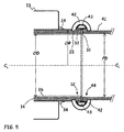
図5は、フランジレスプロセスカップリング12の断面模式図で、プロセス流パイプ41への代替の終端間接続を示す。本実施形態において、流体接続は、外部終端間ガスケット密閉と共に、フランジレスプロセスカップリング12に対合することにより、パイプ部分14とプロセスパイプ41との間に外部終端間カップリングを形成する、外部カップラー42および外部ガスケット43により形成される。
FIG. 5 is a schematic cross-sectional view of the
より具体的には、フランジレスカップリング構造部12は、組み合わせまたは統合型保持環と、ガスケット座と、ライナー保護部と、を備え、カップリング要素32が、外部ガスケット座を提供し、カップリング要素31は、外部カップラー42を保持するためのカップリング溝を提供する。概して、カップリング溝は、パイプ部分14の外半径ORよりも小さい外半径を有し、パイプ部分14の外半径は、保持要素33と遷移部15との間で測定される。対照的に、保持環は、パイプ部分14の外半径ORと同じ、またはこれよりも大きい外半径を有する。
More specifically, the
一部の実施形態において、ガスケット座および保持要素は、関連する機械的固定器具と共に、Victaulic(登録商標)式の外部カップラー42および外部ガスケット43に対応する。これらのカップラーは、米国ペンシルバニア州イーストンのVictaulic Companyから、広範囲のサイズおよび構成において販売されている。他の実施形態において、フランジレスプロセスカップリング12は、他のいくつかの販売会社から販売されるように、様々な外部カップラー/ガスケットおよび機械的固定器具設計に対して構成される。
In some embodiments, the gasket seat and retaining element, along with associated mechanical fasteners, correspond to a Victical® type
図4および5は、フランジレスカップリングデバイス12が、内部および外部の両方のガスケット密閉を含む、多種多様な終端間および外部カップリング形状に構成可能であることを示す。具体的には、保持要素(またはカップリング要素)は、広範囲の保持溝、保持スロット、保持リング、保持環および他の保持形状、ならびに等しく広範囲の内部および外部ガスケット形状に構成可能である。これらは、ポリマー上に金属のカップリング面および金属上に金属のカップリング面の両方を含む。
4 and 5 show that the
フランジ付きまたは面対面流体密閉を形成する、先行の既存の高圧、高流量カップリング構造とは対照的に、図4および5に示される終端間または直管接続は、貫通穴フランジ固定器具を必要としない。このため、フランジレスカップリング12は、ボルトを使用しない。つまり、カップリング12のいかなる要素の穴を通って延在する機械的固定器具も存在しない。機械的固定器具は、パイプ部分14およびプロセス流パイプ41の周囲で外部カップラー42を圧迫するために使用されるが、これらは、カップリング12で流体接続を通して、またはこれを横切って物理的に延在しない。
In contrast to the previous existing high pressure, high flow coupling structures that form a flanged or face-to-face fluid seal, the end-to-end or straight pipe connection shown in FIGS. 4 and 5 requires a through-hole flange fixture. And not. For this reason, the
さらに、フランジレスプロセスカップリング12は、対向するフランジ間に面対面密閉を形成するフランジガスケットを必要としない。代わりに、フランジレスプロセスカップリング12は、外部カップラー42により圧迫されると、ガスケット座32に対して密閉を形成する、フランジレスガスケットを採用する。従来のより低圧流体のカップリングとは対照的に、外部プロセスカップリング12は、ネジ山もない。つまり、これらは、概して、外部の機械的固定器具上で使用されるが、圧力または流体密閉自体に関与するネジ山は存在しない。
Further, the
これらの設計は、磁気式流量計の用途のために顕著な利点を有する。特に、ライナー保護部31、ガスケット座32および保持要素33を備えるフランジレスプロセスカップリング12は、剛性および可塑性両方のプロセス流体接続に適合可能である。前者の設計は、磁気式流量計が、屈曲に対応、または地震応力を低減するために、プロセスパイプ41に対する制限された範囲の動きを可能にする。後者の設計は、相対的な動きを低減し、機械的振動の範囲を低減する。
These designs have significant advantages for magnetic flow meter applications. In particular, the
また、フランジレスプロセスカップリング12は、フランジ付きおよび貫通ボルト付き設計よりも容易な整合も提供する。特に、外部カップラー筐体42は、貫通穴ボルトまたは他の機械的固定器具をフランジまたは他の密閉構造に挿入する前に、より完全な整合を必要とするのではなく、カップリングの形成中(つまり、機械的固定器具を締め付け中)構造部12とプロセスパイプ41との整合を完了する。このように、フランジレスプロセスカップリング12は、専用アダプタ金具の必要性を低減し、かつ設置期間の要件を減少することにより、より迅速で容易な保守を容易にし、かつ全体的な運用コストを低減して、既存の流体処理構造に大幅な改造を必要とせずに、磁気式流量計の可能な設置範囲を増加させることになる。
The
本発明は、好ましい実施形態を参照して説明されてきたが、使用された用語は、説明の目的であって、制限を目的とするものではない。当業者は、本発明の精神および範囲を逸脱することなく、形状および詳細に変更が行われ得ることを理解するであろう。 Although the present invention has been described with reference to a preferred embodiment, the terminology used is for the purpose of description and not for the purpose of limitation. Those skilled in the art will appreciate that changes can be made in form and detail without departing from the spirit and scope of the invention.
Claims (24)
パイプ部分と、
プロセス流路を形成するように前記パイプ部分の内側を覆うポリマー絶縁ライナーと、
前記プロセス流路への終端間流体接続部を形成するために、前記パイプ部分の終端上に配置されるフランジレス保持環と、
前記ポリマー絶縁ライナーに終端密閉部を提供するように、前記フランジレス保持環上に形成されるライナー保護部と、を備え、前記終端密閉部は、前記ライナー保護部と前記ポリマー絶縁ライナーの環状端部との間の接触によって形成され、
さらに、前記プロセス流路の内側に磁場を生成するためのコイルと、
前記プロセス流路の内側の磁場の中を通る流体流によって生成される起電力を検知するための起電力センサと、を備え、
前記フランジレス保持環と前記ライナー保護部は、非磁性金属で形成される、磁気式流量計本体。 A magnetic flow meter body,
A pipe part,
A polymer insulating liner covering the inside of the pipe portion to form a process flow path;
A flangeless retaining ring disposed on an end of the pipe portion to form an end-to-end fluid connection to the process flow path;
A liner protector formed on the flangeless retaining ring to provide an end seal for the polymer insulating liner, the terminal seal being an annular end of the liner protector and the polymer insulating liner. Formed by contact between the parts,
A coil for generating a magnetic field inside the process flow path;
An electromotive force sensor for detecting an electromotive force generated by a fluid flow passing through a magnetic field inside the process flow path,
The magnetic flowmeter body, wherein the flangeless retaining ring and the liner protection part are formed of a nonmagnetic metal.
測定器本体と、フランジレスカップリング構造部と、を備え、
前記測定器本体は、前記測定器本体の中を通って延在するパイプ部分と、前記パイプ部分の内側を覆うポリマー絶縁ライナーと、前記ポリマー絶縁ライナーを通して延在するプローブと、前記パイプ部分内部に磁場を生成するためのコイルと、を備え、
前記フランジレスカップリング構造部は、前記パイプ部分の終端上に形成される環状の保持要素と、前記保持要素上に形成される環状のライナー保護部と、を備え、前記ライナー保護部は、前記ライナー保護部と前記ポリマー絶縁ライナーの環状端部との間の接触によって、終端密閉部を前記ポリマー絶縁ライナー上に形成し、
前記ライナー保護部および前記保持要素は、非磁性金属で形成される、磁気式流量計。 A magnetic flow meter,
A measuring instrument body and a flangeless coupling structure,
The meter body includes a pipe portion that extends through the meter body, a polymer insulating liner that covers the inside of the pipe portion, a probe that extends through the polymer insulating liner, and an interior of the pipe portion. A coil for generating a magnetic field,
The flangeless coupling structure includes an annular holding element formed on an end of the pipe portion, and an annular liner protective part formed on the holding element, and the liner protective part includes A terminal seal is formed on the polymer insulating liner by contact between the liner protector and the annular end of the polymer insulating liner;
The liner protective part and the holding element are magnetic flowmeters formed of a nonmagnetic metal.
前記磁気式流量計を通るプロセス流路を形成するように、ポリマー絶縁ライナーでパイプ部分の内側を覆うステップと、
前記パイプ部分の終端上にフランジレスカップリング構造部を形成するステップと、
前記フランジレスカップリング構造部上に、ライナー保護部を、前記ライナー保護部と前記ポリマー絶縁ライナーの環状端部との間の接触によって前記ポリマー絶縁ライナーの終端密閉部を形成するように溶接するステップと、を含み、
前記ライナー保護部および前記ポリマー絶縁ライナーは、等しい内径を有し、かつ前記パイプ部分、前記フランジレス結合構造部および前記ライナー保護部は、各々非磁性金属で形成される、方法。 A method for manufacturing a magnetic flow meter comprising:
Covering the inside of the pipe portion with a polymer insulating liner so as to form a process flow path through the magnetic flow meter;
Forming a flangeless coupling structure on an end of the pipe portion;
Welding the liner protector on the flangeless coupling structure so as to form an end seal of the polymer insulating liner by contact between the liner protector and the annular end of the polymer insulating liner; And including
The liner protector and the polymer insulating liner have equal inner diameters, and the pipe portion, the flangeless coupling structure, and the liner protector are each formed of a non-magnetic metal.
Applications Claiming Priority (3)
| Application Number | Priority Date | Filing Date | Title |
|---|---|---|---|
| US2374208P | 2008-01-25 | 2008-01-25 | |
| US61/023,742 | 2008-01-25 | ||
| PCT/US2009/000397 WO2009094156A1 (en) | 2008-01-25 | 2009-01-22 | Flangeless magnetic flowmeter with integrated retention collar, valve seat and liner protector |
Publications (3)
| Publication Number | Publication Date |
|---|---|
| JP2011510326A JP2011510326A (en) | 2011-03-31 |
| JP2011510326A5 JP2011510326A5 (en) | 2012-05-17 |
| JP5399413B2 true JP5399413B2 (en) | 2014-01-29 |
Family
ID=40897868
Family Applications (1)
| Application Number | Title | Priority Date | Filing Date |
|---|---|---|---|
| JP2010544325A Expired - Fee Related JP5399413B2 (en) | 2008-01-25 | 2009-01-22 | Flangeless magnetic flow meter with integrated retaining ring, valve seat, and liner protector |
Country Status (5)
| Country | Link |
|---|---|
| US (1) | US7637169B2 (en) |
| EP (1) | EP2240745B1 (en) |
| JP (1) | JP5399413B2 (en) |
| CN (1) | CN101925802B (en) |
| WO (1) | WO2009094156A1 (en) |
Families Citing this family (30)
| Publication number | Priority date | Publication date | Assignee | Title |
|---|---|---|---|---|
| US8393233B2 (en) * | 2006-10-13 | 2013-03-12 | Guixian Lu | Force meter |
| US9182258B2 (en) * | 2011-06-28 | 2015-11-10 | Rosemount Inc. | Variable frequency magnetic flowmeter |
| DE102012016401A1 (en) * | 2011-11-20 | 2013-05-23 | Krohne Ag | Magnetizing device for a nuclear magnetic flowmeter |
| DE102012103685A1 (en) * | 2012-04-26 | 2013-10-31 | Endress + Hauser Flowtec Ag | Measuring tube for a flowmeter |
| US8806956B2 (en) * | 2012-05-16 | 2014-08-19 | Rosemount Inc. | Fastening system for magnetic flowmeter liner |
| US9021890B2 (en) | 2012-09-26 | 2015-05-05 | Rosemount Inc. | Magnetic flowmeter with multiple coils |
| US8991264B2 (en) | 2012-09-26 | 2015-03-31 | Rosemount Inc. | Integrally molded magnetic flowmeter |
| US9027418B2 (en) * | 2012-09-28 | 2015-05-12 | Rosemount Inc. | Magnetic flowmeter |
| US9127974B2 (en) | 2013-03-09 | 2015-09-08 | Rosemount Inc. | Magnetic flowmeter assembly framework |
| EP2816326B1 (en) * | 2013-06-17 | 2019-11-06 | Nxp B.V. | Flow sensor |
| DE102013108117A1 (en) * | 2013-07-30 | 2015-02-05 | Endress + Hauser Flowtec Ag | Field device and device for conducting a fluid |
| US10663331B2 (en) | 2013-09-26 | 2020-05-26 | Rosemount Inc. | Magnetic flowmeter with power limit and over-current detection |
| DE102013114428A1 (en) | 2013-12-19 | 2015-06-25 | Endress + Hauser Flowtec Ag | Measuring tube for a magnetic-inductive flowmeter and electromagnetic flowmeter |
| US9222815B2 (en) | 2013-12-30 | 2015-12-29 | Rosemount Inc. | Wafer style insertable magnetic flowmeter with collapsible petals |
| US9631962B2 (en) | 2014-03-18 | 2017-04-25 | Rosemount Inc. | Magnetic core configuration for magnetic flowmeters having a plurality of layers of magnetically permeable material |
| US10107700B2 (en) | 2014-03-24 | 2018-10-23 | Rosemount Inc. | Process variable transmitter with process variable sensor carried by process gasket |
| US9316514B2 (en) * | 2014-03-26 | 2016-04-19 | Rosemount Inc. | High pressure wafer style magnetic flowmeter |
| US9464926B2 (en) * | 2014-09-23 | 2016-10-11 | Micro Motion, Inc. | Magnetic flowmeter flowtube assembly with spring-energized seal rings |
| US9410831B2 (en) * | 2014-09-23 | 2016-08-09 | Micro Motion, Inc. | Magnetic flowmeter flowtube assembly with spring-energized seal rings |
| US9464927B2 (en) * | 2014-09-30 | 2016-10-11 | Micro Motion, Inc. | Magnetic flowmeter flowtube with process fluid venting assembly |
| US9255825B1 (en) | 2014-09-30 | 2016-02-09 | Rosemount Inc. | Self-aligning wafer-style process instrument |
| US9488511B2 (en) * | 2014-09-30 | 2016-11-08 | Rosemount Inc. | Magnetic flowmeter with vapor permeation sensor |
| US10969260B1 (en) * | 2017-11-03 | 2021-04-06 | Thompson Equipment Company, Inc. | Magmeter and method of assembly |
| CN107796445A (en) * | 2017-12-06 | 2018-03-13 | 博维恩冷冻科技(苏州)有限公司 | A kind of flowmeter with protective cover |
| US11173634B2 (en) | 2018-02-01 | 2021-11-16 | Ina Acquisition Corp | Electromagnetic radiation curable pipe liner and method of making and installing the same |
| US10704728B2 (en) | 2018-03-20 | 2020-07-07 | Ina Acquisition Corp. | Pipe liner and method of making same |
| CN108646079B (en) * | 2018-06-29 | 2019-06-28 | 苏州大学 | Lower stray electrical current non-contact detection method coexists in a kind of different buried depth pipeline |
| CN109141550B (en) * | 2018-09-27 | 2020-05-22 | 麦克传感器股份有限公司 | Built-in electrode and lining packaging structure of electromagnetic flowmeter sensor |
| US11365994B2 (en) | 2020-06-19 | 2022-06-21 | Micro Motion, Inc. | Magnetic flowmeter flow tube assembly liner |
| US11415441B2 (en) | 2020-09-17 | 2022-08-16 | Micro Motion, Inc. | Magnetic flowmeter composite flow tube liner |
Family Cites Families (79)
| Publication number | Priority date | Publication date | Assignee | Title |
|---|---|---|---|---|
| US715127A (en) | 1902-08-30 | 1902-12-02 | James Phillips Norton | Package-box for stationery. |
| US1216071A (en) * | 1916-08-09 | 1917-02-13 | Alfred H Carstensen | Hat-box. |
| US1271542A (en) * | 1917-10-09 | 1918-07-09 | William B Crenshaw | Hat-box. |
| US1707969A (en) * | 1927-10-14 | 1929-04-02 | Christean Iverson Inc | Filing device |
| US2180691A (en) * | 1938-06-06 | 1939-11-21 | Great Southern Box Company Inc | Folding display carton |
| US2667297A (en) * | 1950-04-03 | 1954-01-26 | Mcreary Ronald | Handled carton for bakery products and the like |
| US2721022A (en) * | 1951-11-01 | 1955-10-18 | William J Billerbeck | Shipping carton |
| US2797039A (en) | 1954-03-01 | 1957-06-25 | Belsinger Inc | Easy packing upright container |
| US3015430A (en) * | 1957-11-18 | 1962-01-02 | Robert E Bauer | Container construction |
| FR1227491A (en) | 1959-04-02 | 1960-08-22 | Cooperative Laitiere Agricole | Packaging |
| US3058583A (en) * | 1960-11-17 | 1962-10-16 | Paul B Williams | Storage cartons for tabulating cards |
| US3410476A (en) * | 1966-05-11 | 1968-11-12 | Brown Co | Recloseable carton having improved tear strip |
| US3441193A (en) * | 1967-11-16 | 1969-04-29 | James W Castle | Side loading egg case |
| US3603501A (en) * | 1969-02-06 | 1971-09-07 | Robert E Confer | Carton having tear strips for cans |
| US3638853A (en) * | 1970-10-15 | 1972-02-01 | Universal Packaging Corp | Boxboard carton closure |
| US3797728A (en) * | 1971-05-03 | 1974-03-19 | Brown Co | Top-opening carton having an unique end flap arrangement |
| US3712531A (en) * | 1971-09-24 | 1973-01-23 | R Mccall | Mailing folder |
| US4000849A (en) * | 1972-12-06 | 1977-01-04 | Robertshaw Controls Company | Temperature responsive valve |
| US3858720A (en) * | 1973-02-23 | 1975-01-07 | Media Systems Corp | Curriculum container assembly |
| US3831834A (en) * | 1973-04-09 | 1974-08-27 | Fibreboard Corp | End opening container with improved stacking strength |
| US3863834A (en) * | 1973-10-09 | 1975-02-04 | Somerville Ind Limited | Tear-Strip for Paperboard Container |
| GB1545469A (en) | 1976-04-30 | 1979-05-10 | Alliance Box Co Ltd | Cartons |
| US4008849A (en) | 1976-05-14 | 1977-02-22 | Boise Cascade Corporation | Bidirectional tear strip means for cartons and the like |
| US4098118A (en) * | 1977-02-23 | 1978-07-04 | Fischer & Porter Co. | Unitary electromagnetic flowmeter |
| US4497212A (en) * | 1977-02-23 | 1985-02-05 | Fischer & Porter Company | Flangeless electromagnetic flowmeter |
| US4214477A (en) * | 1978-12-07 | 1980-07-29 | Fischer & Porter Co. | Flangeless electromagnetic flowmeter |
| USRE31444E (en) * | 1980-10-31 | 1983-11-15 | Two-phase transformer and welding circuit therefor | |
| IT8120590V0 (en) * | 1981-01-26 | 1981-01-26 | Meschi Ind Grafica | OPENABLE PACKAGE, IN PARTICULAR FOR SHEET MATERIALS. |
| US4361236A (en) * | 1981-02-04 | 1982-11-30 | Champion International Corporation | Carton for mailing and storage of checks |
| JPS57155425U (en) * | 1981-03-26 | 1982-09-30 | ||
| US4470309A (en) * | 1981-07-06 | 1984-09-11 | Tokyo Shibaura Denki Kabushiki Kaisha | Electromagnetic flowmeter |
| DE3211967C2 (en) | 1982-03-31 | 1984-01-19 | Siemens AG, 1000 Berlin und 8000 München | Circuit arrangement for a device with which different operating and test sequences are effected and evaluated, in particular for traffic simulation in telephone switching systems |
| US4512477A (en) * | 1983-04-08 | 1985-04-23 | Densen Mark S | Readily erectable wardrobe cabinet and a mode of packaging the same |
| US4583679A (en) * | 1984-01-17 | 1986-04-22 | Manville Service Corporation | Resealable paperboard package |
| GB8605113D0 (en) | 1986-03-01 | 1986-04-09 | Procter & Gamble | Easy-opening device for shipping/display container |
| US4844262A (en) * | 1986-06-24 | 1989-07-04 | Allied Paper Incorporated | Easy access, moisture resistant, resuable, two-piece carton |
| US4753348A (en) * | 1986-06-24 | 1988-06-28 | Allied Paper Incorporated | Easy access, moisture resistant, reusable, two-piece carton |
| JPS6354028U (en) * | 1986-09-25 | 1988-04-11 | ||
| IT208805Z2 (en) * | 1986-10-30 | 1988-05-28 | In Pak Spa | PERFECTED CONTAINER FOR VARIOUS ITEMS |
| US4727755A (en) * | 1986-12-08 | 1988-03-01 | Fischer & Porter Co. | Electromagnetic flowmeter with alternating permanent magnet field |
| DE3735515C2 (en) * | 1987-10-20 | 1998-04-09 | Fischer & Porter Gmbh | Device for inductive flow measurement with a measuring tube made of ceramic, glass, metal or plastic |
| US4834242A (en) * | 1988-02-09 | 1989-05-30 | The Standard Register Company | Shipping, storage and handling arrangement for sheet and continuous business forms |
| US4925019A (en) * | 1988-11-16 | 1990-05-15 | Federal Paper Board | Article carrier with end panels |
| GB8906466D0 (en) * | 1989-03-21 | 1989-05-04 | Premier Brands Uk | Improvements relating to packaging containers |
| US4951824A (en) * | 1989-05-12 | 1990-08-28 | James River Corporation | Carton having an opening feature and a carton blank |
| GB8920336D0 (en) * | 1989-09-08 | 1989-10-25 | Reed Packaging Ltd | Carton and blank for making the same |
| US4955925A (en) * | 1989-09-13 | 1990-09-11 | Platti Rita J | Raker taker I |
| JP3049811B2 (en) * | 1991-03-29 | 2000-06-05 | 株式会社島津製作所 | Electromagnetic flow meter |
| US5259631A (en) * | 1992-04-14 | 1993-11-09 | Bruce Brande | Embroidery floss and accessories box |
| TW264451B (en) * | 1992-07-28 | 1995-12-01 | M Pak Ltd | |
| JP2770675B2 (en) * | 1992-09-30 | 1998-07-02 | 株式会社日立製作所 | Capacitive electromagnetic flowmeter |
| US5325989A (en) * | 1993-05-04 | 1994-07-05 | Eagle Paper Box Company | Box and blank for packaging powdered soap or the like |
| US5348147A (en) * | 1993-09-08 | 1994-09-20 | Moore Business Forms, Inc. | Carton for bulk pack cut single paper |
| BR9507435A (en) * | 1994-03-24 | 1997-09-16 | Union Camp Corp | Side opening box containing a thermal barrier |
| JPH07280612A (en) * | 1994-04-11 | 1995-10-27 | Yamatake Honeywell Co Ltd | Sanitary electromagnetic flowmeter |
| US5487506A (en) * | 1994-06-22 | 1996-01-30 | Sonoco Products Company | Easy-open container having an improved reinforcing and tear strip |
| JPH0875062A (en) * | 1994-09-09 | 1996-03-19 | Hitachi Ltd | Turn lock structure for sanitary ferrule joint |
| US5632632A (en) * | 1994-09-29 | 1997-05-27 | Rosemount Inc. | Flowmeter alignment device |
| JP3265172B2 (en) * | 1995-12-14 | 2002-03-11 | 株式会社山武 | Electromagnetic flowmeter detector |
| US5797039A (en) * | 1995-12-29 | 1998-08-18 | Intel Corporation | Method of efficiently sending packets onto a network by eliminating an interrupt |
| GB2314902B (en) | 1996-06-24 | 2000-01-19 | Abb Kent Taylor Ltd | Flowmeter |
| US5813597A (en) * | 1996-10-15 | 1998-09-29 | Ethicon Endo-Surgery, Inc. | Dual orientation dispenser carton |
| GB2319510A (en) | 1996-11-22 | 1998-05-27 | Xerox Corp | Packaging |
| US5988370A (en) * | 1997-06-23 | 1999-11-23 | Roemer; Donald A. | Corrugated fibreboard container with at least one hinged side and blanks for assembling said container |
| DE19918991A1 (en) | 1999-04-27 | 2000-11-02 | Faller Kg August | Folded cardboard box with fold-out pouring spout has side walls with apertures, and opening limitation flaps on front wall engage into apertures |
| US6227444B1 (en) * | 2000-02-17 | 2001-05-08 | Pama Enterprises, Inc. | Expandable envelope construction |
| KR100690216B1 (en) * | 2000-02-22 | 2007-03-12 | 히사미쓰 세이야꾸 가부시키가이샤 | Packaging bag |
| US6283293B1 (en) * | 2000-04-04 | 2001-09-04 | C. Brown Lingamfelter | Container for providing easy access to beverage cans |
| ATE278615T1 (en) | 2000-07-03 | 2004-10-15 | Swatch Group Man Serv Ag | BOX WITH LID AND FRONT FLAP MADE FROM A ONE-PIECE BLANK WITHOUT ADHESION |
| US6352157B1 (en) * | 2000-09-08 | 2002-03-05 | Ponniah Srinivasan | Shipping container reusable as a hanging file folder container |
| US6578736B2 (en) * | 2001-01-09 | 2003-06-17 | Riverwood International Corporation | Carton with an improved dispensing feature |
| US6422454B1 (en) * | 2001-02-13 | 2002-07-23 | Kraft Foods, Inc. | Flip-top package for shipping and display of a multi-component meal kit |
| JP2002277299A (en) * | 2001-03-21 | 2002-09-25 | Yokogawa Electric Corp | Electromagnetic flowmeter |
| US7140493B2 (en) * | 2002-03-19 | 2006-11-28 | International Paper Company | Tongue lock for stackable containers |
| JP4787763B2 (en) * | 2003-12-12 | 2011-10-05 | ローズマウント インコーポレイテッド | Adjustable empty pipe function |
| EP1827994A2 (en) | 2004-12-03 | 2007-09-05 | International Paper Company | Lidded container with tear-away opening strip and lid deflection take-up means |
| DE102005044677A1 (en) | 2005-09-19 | 2007-03-29 | Abb Patent Gmbh | Electromagnetic flowmeter with a ground washer |
| JP4941703B2 (en) * | 2006-03-16 | 2012-05-30 | 横河電機株式会社 | Electromagnetic flow meter |
| JP2007304040A (en) * | 2006-05-15 | 2007-11-22 | Yokogawa Electric Corp | Electromagnetic flowmeter |
-
2008
- 2008-04-11 US US12/082,456 patent/US7637169B2/en active Active
-
2009
- 2009-01-22 CN CN200980102966.3A patent/CN101925802B/en active Active
- 2009-01-22 JP JP2010544325A patent/JP5399413B2/en not_active Expired - Fee Related
- 2009-01-22 WO PCT/US2009/000397 patent/WO2009094156A1/en active Application Filing
- 2009-01-22 EP EP09704486.1A patent/EP2240745B1/en active Active
Also Published As
| Publication number | Publication date |
|---|---|
| EP2240745B1 (en) | 2021-10-13 |
| JP2011510326A (en) | 2011-03-31 |
| CN101925802A (en) | 2010-12-22 |
| EP2240745A1 (en) | 2010-10-20 |
| US7637169B2 (en) | 2009-12-29 |
| CN101925802B (en) | 2012-11-07 |
| US20090188327A1 (en) | 2009-07-30 |
| WO2009094156A1 (en) | 2009-07-30 |
| EP2240745A4 (en) | 2014-04-09 |
Similar Documents
| Publication | Publication Date | Title |
|---|---|---|
| JP5399413B2 (en) | Flangeless magnetic flow meter with integrated retaining ring, valve seat, and liner protector | |
| EP2350576B1 (en) | Transmitter for a magnetic flowmeter | |
| JP5497759B2 (en) | High-pressure electromagnetic flow meter comprising an electrode assembly with stress resistance | |
| EP2726826B1 (en) | Variable frequency magnetic flowmeter | |
| RU2659463C2 (en) | Magnetic flowmeter with polytetrafluoroethylene electrodes | |
| EP3123122B1 (en) | High pressure wafer style magnetic flowmeter | |
| EP3676570B1 (en) | Conductive polymer reference connection for magnetic flowmeter | |
| Ranges | 2.10 Magnetic Flowmeters A |
Legal Events
| Date | Code | Title | Description |
|---|---|---|---|
| A621 | Written request for application examination |
Free format text: JAPANESE INTERMEDIATE CODE: A621 Effective date: 20120120 |
|
| A521 | Request for written amendment filed |
Free format text: JAPANESE INTERMEDIATE CODE: A523 Effective date: 20120326 |
|
| A977 | Report on retrieval |
Free format text: JAPANESE INTERMEDIATE CODE: A971007 Effective date: 20130613 |
|
| A131 | Notification of reasons for refusal |
Free format text: JAPANESE INTERMEDIATE CODE: A131 Effective date: 20130626 |
|
| A521 | Request for written amendment filed |
Free format text: JAPANESE INTERMEDIATE CODE: A523 Effective date: 20130905 |
|
| TRDD | Decision of grant or rejection written | ||
| A01 | Written decision to grant a patent or to grant a registration (utility model) |
Free format text: JAPANESE INTERMEDIATE CODE: A01 Effective date: 20130924 |
|
| A61 | First payment of annual fees (during grant procedure) |
Free format text: JAPANESE INTERMEDIATE CODE: A61 Effective date: 20131023 |
|
| R150 | Certificate of patent or registration of utility model |
Free format text: JAPANESE INTERMEDIATE CODE: R150 Ref document number: 5399413 Country of ref document: JP Free format text: JAPANESE INTERMEDIATE CODE: R150 |
|
| R250 | Receipt of annual fees |
Free format text: JAPANESE INTERMEDIATE CODE: R250 |
|
| R250 | Receipt of annual fees |
Free format text: JAPANESE INTERMEDIATE CODE: R250 |
|
| R250 | Receipt of annual fees |
Free format text: JAPANESE INTERMEDIATE CODE: R250 |
|
| R250 | Receipt of annual fees |
Free format text: JAPANESE INTERMEDIATE CODE: R250 |
|
| R250 | Receipt of annual fees |
Free format text: JAPANESE INTERMEDIATE CODE: R250 |
|
| LAPS | Cancellation because of no payment of annual fees |