JP5396367B2 - Inkjet head manufacturing method - Google Patents

Inkjet head manufacturing method Download PDF

Info

Publication number
JP5396367B2
JP5396367B2 JP2010234623A JP2010234623A JP5396367B2 JP 5396367 B2 JP5396367 B2 JP 5396367B2 JP 2010234623 A JP2010234623 A JP 2010234623A JP 2010234623 A JP2010234623 A JP 2010234623A JP 5396367 B2 JP5396367 B2 JP 5396367B2
Authority
JP
Japan
Prior art keywords
protective film
nozzle plate
pressure chamber
nozzle
ink
Prior art date
Legal status (The legal status is an assumption and is not a legal conclusion. Google has not performed a legal analysis and makes no representation as to the accuracy of the status listed.)
Expired - Fee Related
Application number
JP2010234623A
Other languages
Japanese (ja)
Other versions
JP2012086442A (en
Inventor
実 古谷田
Current Assignee (The listed assignees may be inaccurate. Google has not performed a legal analysis and makes no representation or warranty as to the accuracy of the list.)
Toshiba TEC Corp
Original Assignee
Toshiba TEC Corp
Priority date (The priority date is an assumption and is not a legal conclusion. Google has not performed a legal analysis and makes no representation as to the accuracy of the date listed.)
Filing date
Publication date
Application filed by Toshiba TEC Corp filed Critical Toshiba TEC Corp
Priority to JP2010234623A priority Critical patent/JP5396367B2/en
Publication of JP2012086442A publication Critical patent/JP2012086442A/en
Application granted granted Critical
Publication of JP5396367B2 publication Critical patent/JP5396367B2/en
Expired - Fee Related legal-status Critical Current
Anticipated expiration legal-status Critical

Links

Images

Classifications

    • BPERFORMING OPERATIONS; TRANSPORTING
    • B41PRINTING; LINING MACHINES; TYPEWRITERS; STAMPS
    • B41JTYPEWRITERS; SELECTIVE PRINTING MECHANISMS, i.e. MECHANISMS PRINTING OTHERWISE THAN FROM A FORME; CORRECTION OF TYPOGRAPHICAL ERRORS
    • B41J2202/00Embodiments of or processes related to ink-jet or thermal heads
    • B41J2202/01Embodiments of or processes related to ink-jet heads
    • B41J2202/10Finger type piezoelectric elements

Description

本発明の実施形態は、インクジェットヘッドの製造方法に関する。   Embodiments described herein relate generally to a method for manufacturing an inkjet head.

インクジェットプリンタのインクジェットヘッドは、例えば2つの圧電材料を貼り合わせて形成された基材と、この基材に取り付けられたノズルプレートとを備える。基材には溝状の複数の圧力室が設けられ、この圧力室には圧電材料に電圧を印加するための電極が形成される。圧力室の容積は、電極を介して基材にかけられる電圧に応じて膨張または縮小する。圧力室に供給されたインクは、圧力室の容積変化によって加圧されることで、ノズルプレートに設けられたノズルから吐出される。   An ink jet head of an ink jet printer includes, for example, a base material formed by bonding two piezoelectric materials and a nozzle plate attached to the base material. The substrate is provided with a plurality of groove-shaped pressure chambers, and electrodes for applying a voltage to the piezoelectric material are formed in the pressure chambers. The volume of the pressure chamber expands or contracts depending on the voltage applied to the substrate through the electrodes. The ink supplied to the pressure chamber is ejected from the nozzles provided in the nozzle plate by being pressurized by the change in volume of the pressure chamber.

インクに電流が流れると、インクが変質することにより印刷の品質低下に繋がる。このため、圧力室内に保護膜が形成され、電極から圧力室内のインクに電流が流れることが防止される。この保護膜は、例えばレーザ加工によってノズルプレートにノズルを形成した後、蒸着重合法によって圧力室内に形成される。さらに、この保護膜は、ノズルの内面やノズルプレートの外面にも形成される。   When a current flows through the ink, the quality of the print is degraded due to the change in the quality of the ink. For this reason, a protective film is formed in the pressure chamber, and current is prevented from flowing from the electrode to the ink in the pressure chamber. This protective film is formed in the pressure chamber by vapor deposition polymerization after forming a nozzle on the nozzle plate by laser processing, for example. Furthermore, this protective film is also formed on the inner surface of the nozzle and the outer surface of the nozzle plate.

特開2003−266691号公報Japanese Patent Laid-Open No. 2003-266691

上記のインクジェットヘッドにおいて、保護膜が形成されている箇所は互いに同じ濡れ性を有する。このため、保護膜が形成された圧力室内、ノズルの内面、およびノズルプレートの外面が全て同じ濡れ性を有し、圧力室内のインクがノズルから外部に漏れるおそれがある。インクがノズルから漏れると、印刷時のインク吐出が不安定になってしまう。   In the ink jet head described above, the portions where the protective film is formed have the same wettability. For this reason, the pressure chamber in which the protective film is formed, the inner surface of the nozzle, and the outer surface of the nozzle plate all have the same wettability, and the ink in the pressure chamber may leak from the nozzle to the outside. If ink leaks from the nozzles, ink ejection during printing becomes unstable.

本発明の目的は、インク漏れを防止できるインクジェットヘッドの製造方法を提供することである。   An object of the present invention is to provide an ink jet head manufacturing method capable of preventing ink leakage.

一つの実施の形態に係るインクジェットヘッドの製造方法は、
圧力室が設けられた基材と、前記圧力室の内面を覆って形成された電極と、前記圧力室を塞ぐように前記基材に取り付けられるとともに、前記圧力室に向かって開口するノズルが設けられたノズルプレートと、を備えたインクジェットヘッドの製造方法である。まず、前記ノズルが形成される前の前記ノズルプレートの外面にノズルプレートを保護するための保護フィルムを貼り付ける。前記保護フィルムと前記ノズルプレートとを貫通する前記ノズルを形成する。前記圧力室内の前記電極と、前記圧力室に面する前記ノズルプレートの内面と、前記ノズルの内面と、前記保護フィルムの外面とを覆うとともに前記圧力室に供給されたインクから前記電極を保護する保護膜を形成する。前記保護フィルムの外面に形成された前記保護膜を除去する。前記保護フィルムを除去することで、前記保護膜よりも濡れ性が低い前記ノズルプレートの外面を露出させる。
An ink jet head manufacturing method according to an embodiment includes:
A base material provided with a pressure chamber, an electrode formed to cover the inner surface of the pressure chamber, and a nozzle that is attached to the base material so as to close the pressure chamber and that opens toward the pressure chamber are provided. And a nozzle plate provided with the ink jet head. First, a protective film for protecting the nozzle plate is attached to the outer surface of the nozzle plate before the nozzle is formed. The nozzle penetrating the protective film and the nozzle plate is formed. Covers the electrode in the pressure chamber, the inner surface of the nozzle plate facing the pressure chamber, the inner surface of the nozzle, and the outer surface of the protective film, and protects the electrode from ink supplied to the pressure chamber. A protective film is formed. The protective film formed on the outer surface of the protective film is removed. By removing the protective film, the outer surface of the nozzle plate having lower wettability than the protective film is exposed.

第1の実施の形態に係るインクジェットヘッドを一部切り欠いて示す斜視図。1 is a perspective view showing a partially cutaway ink jet head according to a first embodiment. FIG. 第1の実施の形態のインクジェットヘッドのノズル周辺を図1のF2−F2線に沿って示す断面図。Sectional drawing which shows the nozzle periphery of the inkjet head of 1st Embodiment along the F2-F2 line of FIG. 第1の実施形態において、蓋部材およびノズルプレートが取り付けられる前の基材を示す斜視図。The perspective view which shows the base material before a cover member and a nozzle plate are attached in 1st Embodiment. 第1の実施形態における製造工程の途中のインクジェットヘッドを示す斜視図。The perspective view which shows the inkjet head in the middle of the manufacturing process in 1st Embodiment. 第1の実施形態における製造工程の途中のインクジェットヘッドを図4のF5−F5線に沿って示す断面図。Sectional drawing which shows the inkjet head in the middle of the manufacturing process in 1st Embodiment along the F5-F5 line | wire of FIG. 第1の実施形態において、保護膜の一部が除去された製造工程の途中のインクジェットヘッドを示す断面図。Sectional drawing which shows the inkjet head in the middle of the manufacturing process in which 1st Embodiment removed some protective films. 第2の実施の形態に係る分解されたインクジェットヘッドおよびマニホールドを示す斜視図。The perspective view which shows the inkjet head and the manifold which were decomposed | disassembled based on 2nd Embodiment. 第2の実施形態のインクジェットヘッドおよびマニホールドを図7のF8−F8線に沿って示す断面図。Sectional drawing which shows the inkjet head and manifold of 2nd Embodiment along the F8-F8 line | wire of FIG. 第2の実施形態のインクジェットヘッドのノズル周辺を拡大して示す断面図。Sectional drawing which expands and shows the nozzle periphery of the inkjet head of 2nd Embodiment. 第2の実施形態における製造工程の途中のインクジェットヘッドを示す断面図。Sectional drawing which shows the inkjet head in the middle of the manufacturing process in 2nd Embodiment. 第2の実施形態における保護膜の一部が除去された製造工程の途中のインクジェットヘッドを示す断面図。Sectional drawing which shows the inkjet head in the middle of the manufacturing process from which a part of protective film in 2nd Embodiment was removed.

以下に、図1ないし図6を参照して、インクジェットヘッドの製造方法の第1の実施の形態について説明する。図1は、インクジェットヘッド10を一部切り欠いて示す斜視図である。図2は、図1のF2−F2線に沿ってインクジェットヘッド10のノズル29周辺を示す断面図である。   Hereinafter, a first embodiment of an ink jet head manufacturing method will be described with reference to FIGS. 1 to 6. FIG. 1 is a perspective view showing the inkjet head 10 with a part cut away. FIG. 2 is a cross-sectional view showing the vicinity of the nozzle 29 of the inkjet head 10 along the line F2-F2 in FIG.

図1に示すように、インクジェットヘッド10は、いわゆるエンドシュータ方式のインクジェットヘッドであって、基材13と、蓋部材14と、ノズルプレート15とを備えている。蓋部材14は、基材13の上面13aに取り付けられている。ノズルプレート15は、基材13の前面13bに取り付けられている。   As shown in FIG. 1, the ink jet head 10 is a so-called end shooter type ink jet head, and includes a base material 13, a lid member 14, and a nozzle plate 15. The lid member 14 is attached to the upper surface 13 a of the base material 13. The nozzle plate 15 is attached to the front surface 13 b of the base material 13.

基材13は、例えば、チタン酸ジルコン酸鉛(PZT)製の2枚の圧電板17,18を互いの分極方向を反対向きとするように貼り合わせて形成されている。基材13に、複数の圧力室21が設けられている。   The base material 13 is formed, for example, by bonding two piezoelectric plates 17 and 18 made of lead zirconate titanate (PZT) so that their polarization directions are opposite to each other. A plurality of pressure chambers 21 are provided in the base material 13.

複数の圧力室21は、それぞれ溝状に形成され、基材13の長手方向に互いに平行に並んで設けられている。圧力室21は、それぞれ基材13の上面13aと前面13bとに開口している。圧力室21は、蓋部材14と、ノズルプレート15とによって塞がれている。   The plurality of pressure chambers 21 are each formed in a groove shape, and are provided in parallel with each other in the longitudinal direction of the base material 13. The pressure chambers 21 open to the upper surface 13a and the front surface 13b of the base material 13, respectively. The pressure chamber 21 is closed by the lid member 14 and the nozzle plate 15.

図2に示すように、複数の圧力室21に電極22がそれぞれ形成されている。電極22は、例えばニッケル薄膜によって形成されているが、これに限らず、例えば金や銅で形成されていても良い。   As shown in FIG. 2, electrodes 22 are respectively formed in the plurality of pressure chambers 21. The electrode 22 is formed of, for example, a nickel thin film, but is not limited thereto, and may be formed of, for example, gold or copper.

電極22は、圧力室21の内面を覆って形成されている。なお、電極22は、少なくとも圧力室21の一対の側面21aを覆っていて、かつ両側面の電極は接続している。一対の側面21aは、圧力室21の内面に含まれる。電極22に電圧が印加されると、圧電材料によって形成された基材13が変形し、圧力室21の容積が膨張または縮小する。   The electrode 22 is formed so as to cover the inner surface of the pressure chamber 21. The electrode 22 covers at least the pair of side surfaces 21a of the pressure chamber 21, and the electrodes on both side surfaces are connected. The pair of side surfaces 21 a is included in the inner surface of the pressure chamber 21. When a voltage is applied to the electrode 22, the base material 13 formed of the piezoelectric material is deformed, and the volume of the pressure chamber 21 is expanded or reduced.

図1に示すように、基材13の上面13aに複数の配線24が設けられている。複数の配線24は、例えば上面13aに形成されたニッケル薄膜を、レーザーパターニングすることによって形成されている。複数の配線24は、上面13aの後端と複数の電極22との間に亘ってそれぞれ設けられる。配線24の一端は、電極22に接続されている。   As shown in FIG. 1, a plurality of wirings 24 are provided on the upper surface 13 a of the base material 13. The plurality of wirings 24 are formed, for example, by laser patterning a nickel thin film formed on the upper surface 13a. The plurality of wirings 24 are respectively provided between the rear end of the upper surface 13 a and the plurality of electrodes 22. One end of the wiring 24 is connected to the electrode 22.

一方、配線24の他端は、例えばインクジェットプリンタのプリント回路板に接続される。このプリント回路板は、インクジェットプリンタの制御部から入力される信号に基づいて、配線24を介して電極22に電圧を印加し、基材13を変形させる。   On the other hand, the other end of the wiring 24 is connected to a printed circuit board of an inkjet printer, for example. The printed circuit board applies a voltage to the electrode 22 through the wiring 24 based on a signal input from the control unit of the ink jet printer, and deforms the base material 13.

蓋部材14は、例えば接着によって基材13の上面13aに取り付けられている。蓋部材14に、インク供給経路26が設けられている。インク供給経路26は、複数の圧力室21にそれぞれ開口するとともに、インクタンクに連結される。インクタンクのインクは、インク供給経路26を介して各圧力室21に供給される。   The lid member 14 is attached to the upper surface 13a of the base material 13 by adhesion, for example. An ink supply path 26 is provided in the lid member 14. The ink supply path 26 opens to the plurality of pressure chambers 21 and is connected to the ink tank. The ink in the ink tank is supplied to each pressure chamber 21 via the ink supply path 26.

ノズルプレート15は、ポリイミド製の矩形のフィルムによって形成されている。なお、ノズルプレート15の材料はこれに限らず、レーザ加工が可能な材料であれば良い。ノズルプレート15の厚みは、例えば10〜100μmである。ノズルプレート15は、例えば接着によって、基材13の前面13bに取り付けられている。図2に示すように、ノズルプレート15の内面15aは、圧力室21に面している。   The nozzle plate 15 is formed of a rectangular film made of polyimide. The material of the nozzle plate 15 is not limited to this, and any material that can be laser processed may be used. The thickness of the nozzle plate 15 is, for example, 10 to 100 μm. The nozzle plate 15 is attached to the front surface 13b of the substrate 13 by, for example, adhesion. As shown in FIG. 2, the inner surface 15 a of the nozzle plate 15 faces the pressure chamber 21.

ノズルプレート15は、撥インク膜27を含んでいる。撥インク膜27は、ノズルプレート15の部材本体28に塗布され、ノズルプレート15の外面15bを形成する。撥インク膜27は、例えばフッ素系コート剤によって形成されている。撥インク膜の厚さは、例えば約0.1μmである。   The nozzle plate 15 includes an ink repellent film 27. The ink repellent film 27 is applied to the member main body 28 of the nozzle plate 15 to form the outer surface 15 b of the nozzle plate 15. The ink repellent film 27 is formed of, for example, a fluorine coating agent. The thickness of the ink repellent film is, for example, about 0.1 μm.

ノズルプレート15に、孔である複数のノズル29が設けられている。複数のノズル29は、複数の圧力室21に対応し、ノズルプレート15の長手方向に並んで配置されている。複数のノズル29は、複数の圧力室21に開口している。   A plurality of nozzles 29 that are holes are provided in the nozzle plate 15. The plurality of nozzles 29 correspond to the plurality of pressure chambers 21 and are arranged side by side in the longitudinal direction of the nozzle plate 15. The plurality of nozzles 29 are open to the plurality of pressure chambers 21.

図2に示すように、圧力室21の電極22と、ノズルプレート15の内面15aと、複数のノズル29の内面29aの一部とを覆う保護膜31が形成されている。保護膜31は、例えばパラキシレン系ポリマーによって形成される。具体的に例示すると、いわゆるパリレンC(ポリクロロパラキシリレン)、パリレンN(ポリパラキシリレン)、およびパリレンD(ポリジクロロパラキシリレン)のようなパラキシリレン系ポリマーが適用される。なお、保護膜31はこれに限らず、例えばポリイミドやポリアミドのような他の物質によって形成されても良い。   As shown in FIG. 2, a protective film 31 is formed to cover the electrode 22 of the pressure chamber 21, the inner surface 15 a of the nozzle plate 15, and a part of the inner surfaces 29 a of the plurality of nozzles 29. The protective film 31 is made of, for example, paraxylene-based polymer. Specifically, paraxylylene-based polymers such as so-called parylene C (polychloroparaxylylene), parylene N (polyparaxylylene), and parylene D (polydichloroparaxylylene) are applied. The protective film 31 is not limited to this, and may be formed of other materials such as polyimide and polyamide.

保護膜31の厚さは、例えば1〜10μmである。保護膜31の濡れ性は、ノズルプレート15の外面15bを形成する撥インク膜27の濡れ性よりも高い。保護膜31は、圧力室21の一対の側面21aにそれぞれ形成された電極22を覆うことで、圧力室21に供給されたインクから電極22を保護する。   The thickness of the protective film 31 is, for example, 1 to 10 μm. The wettability of the protective film 31 is higher than the wettability of the ink repellent film 27 that forms the outer surface 15 b of the nozzle plate 15. The protective film 31 protects the electrode 22 from the ink supplied to the pressure chamber 21 by covering the electrode 22 formed on each of the pair of side surfaces 21 a of the pressure chamber 21.

以下に、前記構成のインクジェットヘッド10の製造方法の一例について説明する。図3は、蓋部材14およびノズルプレート15が取り付けられる前の基材13を示す斜視図である。まず、例えば熱硬化性の接着剤を、例えばスクリーン印刷によって一方の圧電板17に塗布する。なお、これに限らず、例えばスピンコータ、スプレー塗布、および刷毛塗りのような、他の方法で接着剤を塗布しても良い。接着剤を塗布した圧電板17に他方の圧電板18を積層する。例えばオートクレーブ装置によって接着剤を熱硬化させることにより、基材13を形成する。なお、接着剤は後の工程で熱硬化させても良い。   Below, an example of the manufacturing method of the inkjet head 10 of the said structure is demonstrated. FIG. 3 is a perspective view showing the base member 13 before the lid member 14 and the nozzle plate 15 are attached. First, for example, a thermosetting adhesive is applied to one piezoelectric plate 17 by, for example, screen printing. However, the present invention is not limited to this, and the adhesive may be applied by other methods such as spin coater, spray coating, and brush coating. The other piezoelectric plate 18 is laminated on the piezoelectric plate 17 coated with an adhesive. For example, the base material 13 is formed by thermosetting the adhesive with an autoclave apparatus. Note that the adhesive may be thermally cured in a later step.

次に、基材13に、複数の圧力室21を形成する。複数の圧力室21は、例えば、ICウェハーの切断に用いられているダイシングソーのダイヤモンドホイールによって、基材13を切削することで形成される。   Next, a plurality of pressure chambers 21 are formed on the base material 13. The plurality of pressure chambers 21 are formed by, for example, cutting the base material 13 with a diamond wheel of a dicing saw used for cutting an IC wafer.

次に、各圧力室21の内面に、電極22を形成する。さらに、基材13の上面13aに配線24を形成する。電極22および配線24は、例えば無電解メッキ法を用いて形成される。次に、レーザ照射によりパターニングを行い、電極22および配線24以外の部位からニッケル薄膜を除去する。   Next, the electrode 22 is formed on the inner surface of each pressure chamber 21. Further, the wiring 24 is formed on the upper surface 13 a of the base material 13. The electrode 22 and the wiring 24 are formed using, for example, an electroless plating method. Next, patterning is performed by laser irradiation to remove the nickel thin film from portions other than the electrode 22 and the wiring 24.

図4は、製造工程の途中のインクジェットヘッド10を示す斜視図である。図5は、図4のF5−F5線に沿って製造工程の途中のインクジェットヘッド10を示す断面図である。基材13に電極22および配線24を形成した後、熱硬化性の接着剤を用いて、基材13の上面13aに蓋部材14を取り付けるとともに、基材13の前面13bにノズル29が形成される前のノズルプレート15を取り付ける。接着剤を熱硬化させることにより、基材13に蓋部材14およびノズルプレート15を固定する。なお、ここで同時に圧電板17,18に塗布された接着剤を熱硬化させても良い。   FIG. 4 is a perspective view showing the inkjet head 10 during the manufacturing process. FIG. 5 is a cross-sectional view showing the inkjet head 10 during the manufacturing process along the line F5-F5 in FIG. After the electrode 22 and the wiring 24 are formed on the base material 13, the lid member 14 is attached to the upper surface 13 a of the base material 13 using a thermosetting adhesive, and the nozzle 29 is formed on the front surface 13 b of the base material 13. The nozzle plate 15 before mounting is attached. The lid member 14 and the nozzle plate 15 are fixed to the base material 13 by thermosetting the adhesive. At this time, the adhesive applied to the piezoelectric plates 17 and 18 may be thermally cured.

ノズルプレート15は、例えばバーコーターを用いて部材本体28に撥インク膜27を塗布することによって形成されている。図4に示すように、あらかじめノズルプレート15の外面15bに、保護フィルム32が貼り付けられている。   The nozzle plate 15 is formed by applying an ink repellent film 27 to the member main body 28 using, for example, a bar coater. As shown in FIG. 4, a protective film 32 is pasted on the outer surface 15 b of the nozzle plate 15 in advance.

保護フィルム32は、例えばポリエステルによって形成される。保護フィルム32の厚さは、例えば10〜30μmである。保護フィルム32は、ノズルプレート15の外面15bの全体を覆っている。   The protective film 32 is made of, for example, polyester. The thickness of the protective film 32 is 10-30 micrometers, for example. The protective film 32 covers the entire outer surface 15 b of the nozzle plate 15.

次に、このノズルプレート15にエキシマレーザのレーザ光を照射して複数のノズル29を形成する。複数のノズル29は、保護フィルム32とノズルプレート15とを貫通し、圧力室21に開口する。なお、これに限らず、例えばあらかじめノズル29が形成されたノズルプレート15を基材13に接着しても良い。   Next, the nozzle plate 15 is irradiated with excimer laser light to form a plurality of nozzles 29. The plurality of nozzles 29 penetrate the protective film 32 and the nozzle plate 15 and open into the pressure chamber 21. For example, the nozzle plate 15 in which the nozzles 29 are formed in advance may be bonded to the substrate 13.

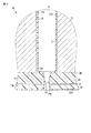
次に、化学気相成長法(CVD)によって保護膜31を形成する。図5に示すように、保護膜31は、各圧力室21内の電極22と、ノズルプレート15の内面15aと、各ノズル29の内面29aと、保護フィルム32の外面32aとを覆って成膜される。   Next, the protective film 31 is formed by chemical vapor deposition (CVD). As shown in FIG. 5, the protective film 31 covers the electrode 22 in each pressure chamber 21, the inner surface 15 a of the nozzle plate 15, the inner surface 29 a of each nozzle 29, and the outer surface 32 a of the protective film 32. Is done.

図6は、保護膜31の一部が除去された製造工程の途中のインクジェットヘッド10を示す断面図である。保護膜31が形成された後、保護フィルム32の外面32aに形成された保護膜31をプラズマ処理することによって除去する。   FIG. 6 is a cross-sectional view showing the inkjet head 10 in the middle of the manufacturing process in which a part of the protective film 31 has been removed. After the protective film 31 is formed, the protective film 31 formed on the outer surface 32a of the protective film 32 is removed by plasma treatment.

プラズマ処理には、例えばヤマト科学製プラズマ照射装置PDC−510をRIEモードで用いる。処理時の条件の一例として、プラズマ出力が100〜200W、ガスは酸素、酸素流量は30ccである。以上の条件で、保護フィルム32の外面32aに向かって30〜120分の間プラズマ処理を行なう。これにより、保護フィルム32の外面32aと、ノズル29の内面29aの一部とに形成された保護膜31が除去される。この際、保護フィルム32の外面32aも多少削れるが、保護フィルム32によってノズルプレート15は保護される。なお、プラズマ処理が不要な部分は、プラズマ処理を行なう前に治具やマスキングテープで覆う。   For the plasma treatment, for example, a plasma irradiation apparatus PDC-510 manufactured by Yamato Scientific is used in the RIE mode. As an example of processing conditions, the plasma output is 100 to 200 W, the gas is oxygen, and the oxygen flow rate is 30 cc. Under the above conditions, plasma treatment is performed for 30 to 120 minutes toward the outer surface 32a of the protective film 32. Thereby, the protective film 31 formed on the outer surface 32a of the protective film 32 and a part of the inner surface 29a of the nozzle 29 is removed. At this time, the outer surface 32 a of the protective film 32 is also slightly cut, but the nozzle plate 15 is protected by the protective film 32. Note that a portion that does not require plasma treatment is covered with a jig or masking tape before plasma treatment is performed.

次に、保護フィルム32をノズルプレート15から剥がして除去する。これにより、図2に示すように、ノズルプレート15の外面15bが外部に露出する。以上により、インクジェットヘッド10の製造工程が終了する。   Next, the protective film 32 is peeled off from the nozzle plate 15 and removed. Thereby, as shown in FIG. 2, the outer surface 15b of the nozzle plate 15 is exposed to the outside. Thus, the manufacturing process of the inkjet head 10 is completed.

前記構成のインクジェットヘッド10の製造方法によれば、圧力室21内の電極22が保護膜31に覆われるとともに、ノズルプレート15の外面15bが保護膜31よりも濡れ性が低い撥インク膜27によって形成されている。このため、圧力室21内の濡れ性とノズルプレート15の外面15bの濡れ性との間に差が生じる。したがって、印字休止時に圧力室21に供給されたインクがノズル29から漏れることを防止でき、印刷時のインク吐出が安定する。   According to the method of manufacturing the inkjet head 10 having the above-described configuration, the electrode 22 in the pressure chamber 21 is covered with the protective film 31, and the outer surface 15 b of the nozzle plate 15 is covered with the ink repellent film 27 having lower wettability than the protective film 31. Is formed. For this reason, a difference arises between the wettability in the pressure chamber 21 and the wettability of the outer surface 15b of the nozzle plate 15. Therefore, it is possible to prevent the ink supplied to the pressure chamber 21 from leaking from the nozzles 29 when printing is stopped, and the ink ejection during printing is stabilized.

次に、図7ないし図11を参照して、インクジェットヘッドの製造方法の第2の実施の形態について説明する。なお、第1の実施形態のインクジェットヘッド10と同一の機能を有する構成部分には同一の参照符号を付してその説明を省略する。   Next, a second embodiment of a method for manufacturing an ink jet head will be described with reference to FIGS. Note that components having the same functions as those of the inkjet head 10 of the first embodiment are denoted by the same reference numerals, and description thereof is omitted.

図7は、分解されたインクジェットヘッド40およびマニホールド41を示す斜視図である。図8は、図7のF8−F8線に沿ってインクジェットヘッド40およびマニホールド41を示す断面図である。   FIG. 7 is a perspective view showing the disassembled inkjet head 40 and manifold 41. FIG. 8 is a cross-sectional view showing the inkjet head 40 and the manifold 41 along the line F8-F8 in FIG.

図7に示すように、インクジェットヘッド40は、いわゆるサイドシュータ方式のインクジェットヘッドであって、基材43と、枠部材44と、ノズルプレート45とを備えている。基材43は、基材本体46と、一対の圧電部材47とを有している。図8に示すように、基材43と、枠部材44と、ノズルプレート45との内側に、インク室49が形成されている。一対の圧電部材47は、インク室49の内部に位置している。   As shown in FIG. 7, the ink jet head 40 is a so-called side shooter type ink jet head, and includes a base material 43, a frame member 44, and a nozzle plate 45. The base material 43 includes a base material body 46 and a pair of piezoelectric members 47. As shown in FIG. 8, an ink chamber 49 is formed inside the base material 43, the frame member 44, and the nozzle plate 45. The pair of piezoelectric members 47 are located inside the ink chamber 49.

基材本体46は、例えばアルミナのようなセラミックスによって、矩形の板状に形成されている。基材本体46は、平坦な第1の面51と、第1の面51の反対側に位置する第2の面52とを有している。第2の面52は、マニホールド41に取り付けられる。基材本体46に、複数の供給口53と、複数の第1の排出口54と、複数の第2の排出口55とが設けられている。   The base body 46 is formed in a rectangular plate shape using ceramics such as alumina. The base body 46 has a flat first surface 51 and a second surface 52 located on the opposite side of the first surface 51. The second surface 52 is attached to the manifold 41. The base body 46 is provided with a plurality of supply ports 53, a plurality of first discharge ports 54, and a plurality of second discharge ports 55.

図7に示すように、複数の供給口53は、基材本体46の中央部に設けられている。複数の供給口53は、基材本体46の長手方向に並んでいる。複数の供給口53は、インク室49に開口している。   As shown in FIG. 7, the plurality of supply ports 53 are provided in the central portion of the base body 46. The plurality of supply ports 53 are arranged in the longitudinal direction of the base body 46. The plurality of supply ports 53 are open to the ink chamber 49.

供給口53は、インクジェットヘッド40がマニホールド41に取り付けられると、マニホールド41を介してインクタンクに連結される。インクタンクのインクは、供給口53からインク室49に供給される。   The supply port 53 is connected to the ink tank via the manifold 41 when the inkjet head 40 is attached to the manifold 41. The ink in the ink tank is supplied from the supply port 53 to the ink chamber 49.

複数の第1の排出口54は、基材本体46の一方の側縁46aに沿って並んで設けられている。複数の第2の排出口55は、基材本体46の他方の側縁46bに沿って並んで設けられている。第1の排出口54と第2の排出口55との間に、供給口53が挟まれている。第1の排出口54と第2の排出口55とは、インク室49に開口している。   The plurality of first discharge ports 54 are provided side by side along one side edge 46 a of the base body 46. The plurality of second discharge ports 55 are provided side by side along the other side edge 46 b of the base body 46. A supply port 53 is sandwiched between the first discharge port 54 and the second discharge port 55. The first discharge port 54 and the second discharge port 55 are open to the ink chamber 49.

第1の排出口54および第2の排出口55は、インクジェットヘッド40がマニホールド41に取り付けられると、マニホールド41を介してインクタンクにそれぞれ連結される。インク室49内のインクは、第1の排出口54および第2の排出口55からインクタンクに戻される。   The first discharge port 54 and the second discharge port 55 are respectively connected to the ink tank via the manifold 41 when the inkjet head 40 is attached to the manifold 41. The ink in the ink chamber 49 is returned to the ink tank from the first discharge port 54 and the second discharge port 55.

枠部材44は、例えば接着によって、基材本体46の第1の面51に隙間無く取り付けられている。枠部材44は、一対の圧電部材47、供給口53、第1の排出口54、および第2の排出口55を囲んでいる。   The frame member 44 is attached to the first surface 51 of the base body 46 with no gap, for example, by adhesion. The frame member 44 surrounds the pair of piezoelectric members 47, the supply port 53, the first discharge port 54, and the second discharge port 55.

ノズルプレート45は、ポリイミド製の矩形のフィルムによって形成されている。ノズルプレート45は、例えば接着によって、枠部材44に隙間無く取り付けられている。ノズルプレート45は、基材本体46の第1の面51に対向している。   The nozzle plate 45 is formed of a rectangular film made of polyimide. The nozzle plate 45 is attached to the frame member 44 without a gap, for example, by adhesion. The nozzle plate 45 faces the first surface 51 of the base body 46.

ノズルプレート45に、孔である複数のノズル58が設けられている。複数のノズル58は、一対の圧電部材47に対応し、基材本体46の長手方向に沿って二列に並んで配置されている。   The nozzle plate 45 is provided with a plurality of nozzles 58 that are holes. The plurality of nozzles 58 correspond to the pair of piezoelectric members 47 and are arranged in two rows along the longitudinal direction of the base body 46.

図9は、インクジェットヘッド40のノズル58周辺を拡大して示す断面図である。図9に示すように、ノズルプレート45は、撥インク膜59を含んでいる。撥インク膜59は、ノズルプレート45の部材本体60に塗布され、ノズルプレート45の外面45bを形成する。撥インク膜59は、第1の実施形態の撥インク膜27と同じく、例えばフッ素系コート剤によって形成されている。撥インク膜の厚さは、例えば約0.1μmである。   FIG. 9 is an enlarged cross-sectional view showing the vicinity of the nozzle 58 of the inkjet head 40. As shown in FIG. 9, the nozzle plate 45 includes an ink repellent film 59. The ink repellent film 59 is applied to the member main body 60 of the nozzle plate 45 to form the outer surface 45 b of the nozzle plate 45. The ink repellent film 59 is formed of, for example, a fluorine coating agent, like the ink repellent film 27 of the first embodiment. The thickness of the ink repellent film is, for example, about 0.1 μm.

図7に示すように、一対の圧電部材47は、基材本体46の第1の面51にそれぞれ取り付けられ、基材本体46の長手方向に互いに平行に延びている。一方の圧電部材47は、供給口53と第1の排出口54との間に配置されている。他方の圧電部材47は、供給口53と第2の排出口55との間に配置されている。   As shown in FIG. 7, the pair of piezoelectric members 47 are respectively attached to the first surface 51 of the base body 46 and extend parallel to each other in the longitudinal direction of the base body 46. One piezoelectric member 47 is disposed between the supply port 53 and the first discharge port 54. The other piezoelectric member 47 is disposed between the supply port 53 and the second discharge port 55.

一対の圧電部材47は、例えば、チタン酸ジルコン酸鉛(PZT)製の2枚の圧電板を互いの分極方向を反対向きとするように貼り合わせてそれぞれ形成されている。一対の圧電部材47は、台形状の断面を有する棒状にそれぞれ形成されている。   The pair of piezoelectric members 47 are formed, for example, by bonding two piezoelectric plates made of lead zirconate titanate (PZT) so that their polarization directions are opposite to each other. The pair of piezoelectric members 47 are each formed in a bar shape having a trapezoidal cross section.

一対の圧電部材47に、複数の圧力室61がそれぞれ形成されている。複数の圧力室61は、圧電部材47が延びる方向とそれぞれ交差する溝である。複数の圧力室61は、それぞれ複数のノズル58と対応して、並んで設けられている。   A plurality of pressure chambers 61 are respectively formed in the pair of piezoelectric members 47. The plurality of pressure chambers 61 are grooves that respectively intersect the direction in which the piezoelectric member 47 extends. The plurality of pressure chambers 61 are provided side by side corresponding to the plurality of nozzles 58.

図8に示すように、複数の圧力室61に、電極62がそれぞれ形成されている。電極62は、圧力室61の側面および底面に形成されている。電極62に電圧が印加されると、圧電部材47が変形し、圧力室61の容積が膨張または縮小する。   As shown in FIG. 8, electrodes 62 are respectively formed in the plurality of pressure chambers 61. The electrode 62 is formed on the side surface and the bottom surface of the pressure chamber 61. When a voltage is applied to the electrode 62, the piezoelectric member 47 is deformed and the volume of the pressure chamber 61 is expanded or reduced.

図7に示すように、基材本体46の第1の面51に、複数の配線64が設けられている。複数の配線64は、例えば第1の面51に形成されたニッケル薄膜を、レーザーパターニングすることによって形成されている。   As shown in FIG. 7, a plurality of wirings 64 are provided on the first surface 51 of the base body 46. The plurality of wirings 64 are formed, for example, by laser patterning a nickel thin film formed on the first surface 51.

幾つかの配線64は、基材本体46の一方の側縁46aと一方の圧電部材47との間に亘って設けられ、一方の圧電部材47の複数の電極62に接続されている。余の配線64は、基材本体46の他方の側縁46bと他方の圧電部材47との間に亘って設けられ、一方の圧電部材47の複数の電極62に接続されている。   Several wires 64 are provided between one side edge 46 a of the base body 46 and one piezoelectric member 47, and are connected to a plurality of electrodes 62 of the one piezoelectric member 47. The surplus wiring 64 is provided between the other side edge 46 b of the base body 46 and the other piezoelectric member 47, and is connected to the plurality of electrodes 62 of the one piezoelectric member 47.

複数の配線64には、一対の圧電部材47を駆動するためのICが接続される。このICは、インクジェットプリンタの制御部から入力される信号に基づいて、配線64を介して電極62に電圧を印加し、圧電部材47を変形させる。   An IC for driving the pair of piezoelectric members 47 is connected to the plurality of wirings 64. The IC applies a voltage to the electrode 62 via the wiring 64 based on a signal input from the control unit of the inkjet printer, and deforms the piezoelectric member 47.

図9に示すように、圧力室61の電極62と、ノズルプレート45の内面45aと、複数のノズル58の内面58aの一部とを覆う保護膜71が形成されている。保護膜71は、第1の実施形態の保護膜31と同様に、例えばパラキシリレン系ポリマーによって形成される。   As shown in FIG. 9, a protective film 71 is formed to cover the electrode 62 of the pressure chamber 61, the inner surface 45 a of the nozzle plate 45, and a part of the inner surfaces 58 a of the plurality of nozzles 58. The protective film 71 is formed of, for example, a paraxylylene polymer, similarly to the protective film 31 of the first embodiment.

保護膜71の厚さは、例えば1〜10μmである。保護膜71の濡れ性は、ノズルプレート45の外面45bを形成する撥インク膜59の濡れ性よりも高い。保護膜71は、圧力室61の内面にそれぞれ形成された電極62を覆うことで、圧力室61に供給されたインクから電極62を保護する。   The thickness of the protective film 71 is, for example, 1 to 10 μm. The wettability of the protective film 71 is higher than the wettability of the ink repellent film 59 that forms the outer surface 45 b of the nozzle plate 45. The protective film 71 covers the electrodes 62 respectively formed on the inner surface of the pressure chamber 61, thereby protecting the electrodes 62 from the ink supplied to the pressure chamber 61.

以下に、前記構成のインクジェットヘッド40の製造方法について説明する。まず、焼成前のセラミックスシート(セラミックスグリーンシート)で構成される基材本体46に、プレス成形によって供給口53と、第1の排出口54と、第2の排出口55とを形成する。続いて、基材本体46を焼成する。   Below, the manufacturing method of the inkjet head 40 of the said structure is demonstrated. First, the supply port 53, the 1st discharge port 54, and the 2nd discharge port 55 are formed in the base-material main body 46 comprised with the ceramic sheet (ceramics green sheet) before baking by press molding. Subsequently, the base body 46 is fired.

次に、基材本体46に一対の圧電部材47を接着する。一対の圧電部材47は、治具を介して基材本体46に位置決めされ、基材本体46に取り付けられる。続いて、一対の圧電部材47のそれぞれの角部に、いわゆるテーパ加工を行う。これによって、一対の圧電部材47のそれぞれの断面が台形状になる。   Next, a pair of piezoelectric members 47 are bonded to the base body 46. The pair of piezoelectric members 47 is positioned on the base body 46 via a jig and attached to the base body 46. Subsequently, so-called taper processing is performed on each corner of the pair of piezoelectric members 47. Thereby, each cross section of the pair of piezoelectric members 47 becomes trapezoidal.

次に、一対の圧電部材47に、複数の圧力室61を形成する。複数の圧力室61は、例えば、ICウェハーの切断に用いられているダイシングソーのダイヤモンドホイールによって形成される。   Next, a plurality of pressure chambers 61 are formed in the pair of piezoelectric members 47. The plurality of pressure chambers 61 are formed by, for example, a diamond wheel of a dicing saw used for cutting an IC wafer.

次に、複数の圧力室61のそれぞれの内面に、電極62を形成する。さらに、基材本体46の第1の面51に複数の配線64を形成する。電極62および配線64は、無電解メッキ法を用い、例えばニッケル薄膜によって形成される。次に、レーザ照射によりパターニングを行い、電極62および配線64以外の部位からニッケル薄膜を除去する。   Next, the electrode 62 is formed on the inner surface of each of the plurality of pressure chambers 61. Further, a plurality of wirings 64 are formed on the first surface 51 of the base body 46. The electrode 62 and the wiring 64 are formed by, for example, a nickel thin film using an electroless plating method. Next, patterning is performed by laser irradiation to remove the nickel thin film from portions other than the electrode 62 and the wiring 64.

図10は、製造工程の途中のインクジェットヘッド40を示す断面図である。電極62および配線64を形成した後、基材本体46に枠部材44を接着する。基材本体46に取り付けられた枠部材44に、ノズルプレート45を接着する。   FIG. 10 is a cross-sectional view showing the inkjet head 40 during the manufacturing process. After forming the electrode 62 and the wiring 64, the frame member 44 is bonded to the base body 46. The nozzle plate 45 is bonded to the frame member 44 attached to the base body 46.

ノズルプレート45は、例えばバーコーターを用いて部材本体60に撥インク膜59を塗布することによって形成されている。図10に示すように、ノズルプレート45の外面45bに、あらかじめ保護フィルム73が貼り付けられている。   The nozzle plate 45 is formed by applying an ink repellent film 59 to the member main body 60 using, for example, a bar coater. As shown in FIG. 10, a protective film 73 is attached in advance to the outer surface 45 b of the nozzle plate 45.

保護フィルム73は、例えばポリエステルによって形成される。保護フィルム73の厚さは、例えば10〜30μmである。保護フィルム73は、ノズルプレート45の外面45bの全体を覆っている。   The protective film 73 is made of polyester, for example. The thickness of the protective film 73 is, for example, 10 to 30 μm. The protective film 73 covers the entire outer surface 45 b of the nozzle plate 45.

次に、このノズルプレート45にレーザ光を照射して複数のノズル58を形成する。複数のノズル58は、保護フィルム73とノズルプレート45とを貫通し、インク室49内の圧力室61に向かって開口する。なお、これに限らず、例えばあらかじめノズル58が形成されたノズルプレート45を基材43に接着しても良い。   Next, the nozzle plate 45 is irradiated with laser light to form a plurality of nozzles 58. The plurality of nozzles 58 pass through the protective film 73 and the nozzle plate 45 and open toward the pressure chamber 61 in the ink chamber 49. For example, the nozzle plate 45 in which the nozzles 58 are formed in advance may be bonded to the base material 43.

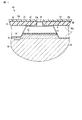
次に、CVDによって保護膜71を形成する。図10に示すように、保護膜71は、各圧力室61内の電極62と、インク室49を形成するノズルプレート45の内面45aおよび基材本体46の第1の面51と、各ノズル58の内面58aと、保護フィルム73の外面73aとを覆って成膜される。   Next, the protective film 71 is formed by CVD. As shown in FIG. 10, the protective film 71 includes electrodes 62 in each pressure chamber 61, an inner surface 45 a of the nozzle plate 45 that forms the ink chamber 49, a first surface 51 of the base body 46, and each nozzle 58. The inner surface 58a of the protective film 73 and the outer surface 73a of the protective film 73 are deposited.

図11は、保護膜71の一部が除去された製造工程の途中のインクジェットヘッド40を示す断面図である。保護膜71が形成された後、第1の実施形態と同様に、保護膜71にプラズマ処理を施す。   FIG. 11 is a cross-sectional view showing the inkjet head 40 in the middle of the manufacturing process from which part of the protective film 71 has been removed. After the protective film 71 is formed, plasma processing is performed on the protective film 71 as in the first embodiment.

プラズマ処理によって、保護フィルム73の外面73aと、ノズル58の内面58aの一部とに形成された保護膜71が除去される。この際、保護フィルム73の外面73aも多少削れるが、保護フィルム73によってノズルプレート45は保護される。   By the plasma treatment, the protective film 71 formed on the outer surface 73a of the protective film 73 and a part of the inner surface 58a of the nozzle 58 is removed. At this time, the outer surface 73 a of the protective film 73 is also slightly cut, but the nozzle plate 45 is protected by the protective film 73.

次に、保護フィルム73をノズルプレート45から剥がして除去する。これにより、図9に示すように、ノズルプレート45の外面45bが外部に露出する。次に、前記ICを基材本体46の第1の面51に固定して配線64に接続する。以上により、インクジェットヘッド40の製造工程が終了する。   Next, the protective film 73 is peeled off from the nozzle plate 45 and removed. Thereby, as shown in FIG. 9, the outer surface 45b of the nozzle plate 45 is exposed to the outside. Next, the IC is fixed to the first surface 51 of the base body 46 and connected to the wiring 64. Thus, the manufacturing process of the inkjet head 40 is completed.

以上のように、第1の実施の形態のインクジェットヘッド10とは異なる方式のインクジェットヘッド40を製造する場合であっても、第1の実施の形態と同様の効果を得ることができる。   As described above, even when the inkjet head 40 of a method different from that of the inkjet head 10 of the first embodiment is manufactured, the same effect as that of the first embodiment can be obtained.

本発明のいくつかの実施形態を説明したが、これらの実施形態は、例として提示したものであり、発明の範囲を限定することは意図していない。これら新規な実施形態は、その他の様々な形態で実施されることが可能であり、発明の要旨を逸脱しない範囲で、種々の省略、置き換え、変更を行うことができる。これら実施形態やその変形は、発明の範囲や要旨に含まれるとともに、特許請求の範囲に記載された発明とその均等の範囲に含まれる。   Although several embodiments of the present invention have been described, these embodiments are presented by way of example and are not intended to limit the scope of the invention. These novel embodiments can be implemented in various other forms, and various omissions, replacements, and changes can be made without departing from the scope of the invention. These embodiments and modifications thereof are included in the scope and gist of the invention, and are included in the invention described in the claims and the equivalents thereof.

10,40…インクジェットヘッド,13,43…基材,15,45…ノズルプレート,15a,45a…ノズルプレートの内面,15b,45b…ノズルプレートの外面,21,61…圧力室,22,62…電極,27,59…撥インク膜,29,58…ノズル,29a,58a…ノズルの内面,31,71…保護膜,32,73…保護フィルム,32a,73a…保護フィルムの外面。   DESCRIPTION OF SYMBOLS 10, 40 ... Inkjet head, 13, 43 ... Base material, 15, 45 ... Nozzle plate, 15a, 45a ... Inner surface of nozzle plate, 15b, 45b ... Outer surface of nozzle plate, 21, 61 ... Pressure chamber, 22, 62 ... Electrodes, 27, 59 ... ink repellent film, 29, 58 ... nozzle, 29a, 58a ... inner surface of nozzle, 31, 71 ... protective film, 32, 73 ... protective film, 32a, 73a ... outer surface of protective film.

Claims (4)

圧力室が設けられた基材と、前記圧力室の内面を覆って形成された電極と、前記圧力室を塞ぐように前記基材に取り付けられるとともに、前記圧力室に向かって開口するノズルが設けられたノズルプレートと、を備えたインクジェットヘッドの製造方法であって、
前記ノズルが形成される前の前記ノズルプレートの外面にノズルプレートを保護するための保護フィルムを貼り付け、
前記保護フィルムと前記ノズルプレートとを貫通する前記ノズルを形成し、
前記圧力室内の前記電極と、前記圧力室に面する前記ノズルプレートの内面と、前記ノズルの内面と、前記保護フィルムの外面とを覆うとともに前記圧力室に供給されたインクから前記電極を保護する保護膜を形成し、
前記保護フィルムの外面に形成された前記保護膜を除去し、
前記保護フィルムを除去することで、前記保護膜よりも濡れ性が低い前記ノズルプレートの外面を露出させることを特徴とするインクジェットヘッドの製造方法。
A base material provided with a pressure chamber, an electrode formed to cover the inner surface of the pressure chamber, and a nozzle that is attached to the base material so as to close the pressure chamber and that opens toward the pressure chamber are provided. A nozzle plate, and an inkjet head manufacturing method comprising:
Affixing a protective film for protecting the nozzle plate on the outer surface of the nozzle plate before the nozzle is formed,
Forming the nozzle penetrating the protective film and the nozzle plate;
Covers the electrode in the pressure chamber, the inner surface of the nozzle plate facing the pressure chamber, the inner surface of the nozzle, and the outer surface of the protective film, and protects the electrode from ink supplied to the pressure chamber. Forming a protective film,
Removing the protective film formed on the outer surface of the protective film;
A method for manufacturing an ink jet head, comprising: removing the protective film to expose an outer surface of the nozzle plate having lower wettability than the protective film.
前記ノズルプレートは、前記ノズルプレートの外面を形成する撥インク膜を含むことを特徴とする請求項1に記載のインクジェットヘッドの製造方法。   The method of manufacturing an ink jet head according to claim 1, wherein the nozzle plate includes an ink repellent film that forms an outer surface of the nozzle plate. 前記保護フィルムの外面に形成された前記保護膜を除去する際に、前記ノズルの内面の少なくとも一部に形成された保護膜をさらに除去することを特徴とする請求項2に記載のインクジェットヘッドの製造方法。   The inkjet head according to claim 2, wherein when removing the protective film formed on the outer surface of the protective film, the protective film formed on at least a part of the inner surface of the nozzle is further removed. Production method. 前記保護膜は、プラズマ処理によって除去されることを特徴とする請求項3に記載のインクジェットヘッドの製造方法。   The method of manufacturing an ink jet head according to claim 3, wherein the protective film is removed by plasma treatment.
JP2010234623A 2010-10-19 2010-10-19 Inkjet head manufacturing method Expired - Fee Related JP5396367B2 (en)

Priority Applications (1)

Application Number Priority Date Filing Date Title
JP2010234623A JP5396367B2 (en) 2010-10-19 2010-10-19 Inkjet head manufacturing method

Applications Claiming Priority (1)

Application Number Priority Date Filing Date Title
JP2010234623A JP5396367B2 (en) 2010-10-19 2010-10-19 Inkjet head manufacturing method

Publications (2)

Publication Number Publication Date
JP2012086442A JP2012086442A (en) 2012-05-10
JP5396367B2 true JP5396367B2 (en) 2014-01-22

Family

ID=46258600

Family Applications (1)

Application Number Title Priority Date Filing Date
JP2010234623A Expired - Fee Related JP5396367B2 (en) 2010-10-19 2010-10-19 Inkjet head manufacturing method

Country Status (1)

Country Link
JP (1) JP5396367B2 (en)

Family Cites Families (3)

* Cited by examiner, † Cited by third party
Publication number Priority date Publication date Assignee Title
JP5332275B2 (en) * 2008-04-07 2013-11-06 セイコーエプソン株式会社 Silicon nozzle substrate manufacturing method, droplet discharge head manufacturing method, and droplet discharge apparatus manufacturing method
JP5315975B2 (en) * 2008-12-19 2013-10-16 セイコーエプソン株式会社 Nozzle substrate, droplet discharge head, droplet discharge apparatus, and manufacturing method thereof
JP5426200B2 (en) * 2009-03-13 2014-02-26 富士フイルム株式会社 Liquid repellent treatment method, nozzle plate, ink jet head, and electronic device

Also Published As

Publication number Publication date
JP2012086442A (en) 2012-05-10

Similar Documents

Publication Publication Date Title
EP1974921B1 (en) Self Aligned Port Hole Opening Process for Ink Jet Print Heads
JP2009233927A (en) Manufacturing method for inkjet head
JP5372054B2 (en) Inkjet head
JP2012187864A (en) Inkjet head
JP5358601B2 (en) Inkjet head
JP2012187717A (en) Inkjet head
JP5473140B2 (en) Ink jet head and manufacturing method thereof
JP5768037B2 (en) Inkjet head
JP4508595B2 (en) Liquid ejecting head, manufacturing method thereof, and liquid ejecting apparatus
JP2015051569A (en) Ink jet head and production method thereof
JP5396367B2 (en) Inkjet head manufacturing method
JP5936986B2 (en) Inkjet head and inkjet head manufacturing method
US20140240400A1 (en) Flow path unit, liquid ejecting head, liquid ejecting apparatus, and flow path unit manufacturing method
JP5866273B2 (en) Inkjet head
US9028050B2 (en) Flow path unit, liquid ejecting head, liquid ejecting apparatus, and method of manufacturing flow path unit
JP2013188892A (en) Inkjet head
US10569541B2 (en) Liquid ejection head
JP2013188954A (en) Inkjet head and method of manufacturing the same
JP5492824B2 (en) Ink jet head and method of manufacturing ink jet head
JP5417296B2 (en) Inkjet head manufacturing method
JP2015051570A (en) Inkjet head, and method for manufacturing the same
JP2004188687A (en) Inkjet head and inkjet recording apparatus
JP5879288B2 (en) Ink jet head and method of manufacturing ink jet head
JP2005254659A (en) Production process of nozzle plate
JP2023148926A (en) Coating head

Legal Events

Date Code Title Description
A621 Written request for application examination

Free format text: JAPANESE INTERMEDIATE CODE: A621

Effective date: 20120830

A131 Notification of reasons for refusal

Free format text: JAPANESE INTERMEDIATE CODE: A131

Effective date: 20130702

A521 Written amendment

Free format text: JAPANESE INTERMEDIATE CODE: A523

Effective date: 20130902

TRDD Decision of grant or rejection written
A01 Written decision to grant a patent or to grant a registration (utility model)

Free format text: JAPANESE INTERMEDIATE CODE: A01

Effective date: 20130924

A61 First payment of annual fees (during grant procedure)

Free format text: JAPANESE INTERMEDIATE CODE: A61

Effective date: 20131021

R150 Certificate of patent or registration of utility model

Free format text: JAPANESE INTERMEDIATE CODE: R150

LAPS Cancellation because of no payment of annual fees