JP5390420B2 - Dispensing device - Google Patents
Dispensing device Download PDFInfo
- Publication number
- JP5390420B2 JP5390420B2 JP2010008114A JP2010008114A JP5390420B2 JP 5390420 B2 JP5390420 B2 JP 5390420B2 JP 2010008114 A JP2010008114 A JP 2010008114A JP 2010008114 A JP2010008114 A JP 2010008114A JP 5390420 B2 JP5390420 B2 JP 5390420B2
- Authority
- JP
- Japan
- Prior art keywords
- cap
- housing
- dispensing device
- opening
- contact
- Prior art date
- Legal status (The legal status is an assumption and is not a legal conclusion. Google has not performed a legal analysis and makes no representation as to the accuracy of the status listed.)
- Active
Links
- 239000007788 liquid Substances 0.000 claims description 2
- 230000004913 activation Effects 0.000 description 4
- 238000001704 evaporation Methods 0.000 description 3
- 230000008020 evaporation Effects 0.000 description 3
- 238000007789 sealing Methods 0.000 description 3
- 238000001035 drying Methods 0.000 description 2
- 239000013543 active substance Substances 0.000 description 1
- 239000002537 cosmetic Substances 0.000 description 1
- 229940079593 drug Drugs 0.000 description 1
- 239000003814 drug Substances 0.000 description 1
- 230000002093 peripheral effect Effects 0.000 description 1
- 230000001681 protective effect Effects 0.000 description 1
Images


Classifications
-
- B—PERFORMING OPERATIONS; TRANSPORTING
- B05—SPRAYING OR ATOMISING IN GENERAL; APPLYING FLUENT MATERIALS TO SURFACES, IN GENERAL
- B05B—SPRAYING APPARATUS; ATOMISING APPARATUS; NOZZLES
- B05B11/00—Single-unit hand-held apparatus in which flow of contents is produced by the muscular force of the operator at the moment of use
- B05B11/0005—Components or details
- B05B11/0027—Means for neutralising the actuation of the sprayer ; Means for preventing access to the sprayer actuation means
- B05B11/0032—Manually actuated means located downstream the discharge nozzle for closing or covering it, e.g. shutters
-
- B—PERFORMING OPERATIONS; TRANSPORTING
- B05—SPRAYING OR ATOMISING IN GENERAL; APPLYING FLUENT MATERIALS TO SURFACES, IN GENERAL
- B05B—SPRAYING APPARATUS; ATOMISING APPARATUS; NOZZLES
- B05B11/00—Single-unit hand-held apparatus in which flow of contents is produced by the muscular force of the operator at the moment of use
- B05B11/0005—Components or details
- B05B11/0027—Means for neutralising the actuation of the sprayer ; Means for preventing access to the sprayer actuation means
-
- B—PERFORMING OPERATIONS; TRANSPORTING
- B05—SPRAYING OR ATOMISING IN GENERAL; APPLYING FLUENT MATERIALS TO SURFACES, IN GENERAL
- B05B—SPRAYING APPARATUS; ATOMISING APPARATUS; NOZZLES
- B05B11/00—Single-unit hand-held apparatus in which flow of contents is produced by the muscular force of the operator at the moment of use
- B05B11/0005—Components or details
- B05B11/0037—Containers
- B05B11/0039—Containers associated with means for compensating the pressure difference between the ambient pressure and the pressure inside the container, e.g. pressure relief means
- B05B11/0044—Containers associated with means for compensating the pressure difference between the ambient pressure and the pressure inside the container, e.g. pressure relief means compensating underpressure by ingress of atmospheric air into the container, i.e. with venting means
-
- B—PERFORMING OPERATIONS; TRANSPORTING
- B05—SPRAYING OR ATOMISING IN GENERAL; APPLYING FLUENT MATERIALS TO SURFACES, IN GENERAL
- B05B—SPRAYING APPARATUS; ATOMISING APPARATUS; NOZZLES
- B05B11/00—Single-unit hand-held apparatus in which flow of contents is produced by the muscular force of the operator at the moment of use
- B05B11/0005—Components or details
- B05B11/0062—Outlet valves actuated by the pressure of the fluid to be sprayed
- B05B11/0064—Lift valves
- B05B11/0067—Lift valves having a valve seat located downstream the valve element (take precedence)
-
- B—PERFORMING OPERATIONS; TRANSPORTING
- B05—SPRAYING OR ATOMISING IN GENERAL; APPLYING FLUENT MATERIALS TO SURFACES, IN GENERAL
- B05B—SPRAYING APPARATUS; ATOMISING APPARATUS; NOZZLES
- B05B11/00—Single-unit hand-held apparatus in which flow of contents is produced by the muscular force of the operator at the moment of use
- B05B11/01—Single-unit hand-held apparatus in which flow of contents is produced by the muscular force of the operator at the moment of use characterised by the means producing the flow
- B05B11/10—Pump arrangements for transferring the contents from the container to a pump chamber by a sucking effect and forcing the contents out through the dispensing nozzle
- B05B11/1028—Pumps having a pumping chamber with a deformable wall
- B05B11/1035—Pumps having a pumping chamber with a deformable wall the pumping chamber being a bellow
-
- B—PERFORMING OPERATIONS; TRANSPORTING
- B05—SPRAYING OR ATOMISING IN GENERAL; APPLYING FLUENT MATERIALS TO SURFACES, IN GENERAL
- B05B—SPRAYING APPARATUS; ATOMISING APPARATUS; NOZZLES
- B05B11/00—Single-unit hand-held apparatus in which flow of contents is produced by the muscular force of the operator at the moment of use
- B05B11/01—Single-unit hand-held apparatus in which flow of contents is produced by the muscular force of the operator at the moment of use characterised by the means producing the flow
- B05B11/10—Pump arrangements for transferring the contents from the container to a pump chamber by a sucking effect and forcing the contents out through the dispensing nozzle
- B05B11/1042—Components or details
- B05B11/1064—Pump inlet and outlet valve elements integrally formed of a deformable material
Description
本発明は、液体媒体のための分配装置であって、ハウジング、媒体貯蔵器、媒体を分配するための出口開口、及び媒体貯蔵器内の容積均等化の目的のための空気取入れのための入口開口を持つ分配装置に関する。ここで一般的な分配装置は、ハウジング上に取付け可能でありかつ取付け状態のときに出口開口を保護するキャップを持つ。 The present invention is a dispensing device for a liquid medium comprising a housing, a medium reservoir, an outlet opening for dispensing the medium, and an inlet for air intake for the purpose of volume equalization in the medium reservoir The present invention relates to a dispensing device having an opening. A typical dispensing device here has a cap that can be mounted on the housing and protects the outlet opening when mounted.
一般的な分配装置は従来技術から知られている。かかる装置の場合、媒体がポンプ装置または別の運搬装置により媒体貯蔵器から出口開口を通して環境に分配されることが提供される。これは特に医薬及び化粧品を分配するために役立つ。分配操作は媒体貯蔵器内の媒体の量を減らす。結果として媒体貯蔵器内に形成される負圧(それはさらなる分配操作に対して障害となる)を防ぐために、一般的な分配装置は入口開口を持ち、それを通して空気が分配装置及び媒体貯蔵器中に流入することができ、そこで空気は分配された媒体の置き換えのために残り、圧力均等化に導く。 Common dispensing devices are known from the prior art. In such a device, it is provided that the medium is distributed to the environment from the medium reservoir through the outlet opening by a pump device or another transport device. This is particularly useful for dispensing medicines and cosmetics. Dispensing operations reduce the amount of media in the media reservoir. In order to prevent the negative pressure that is formed in the media reservoir as a result (which hinders further dispensing operations), a typical dispensing device has an inlet opening through which air can flow in the dispensing device and the media reservoir. Where air remains for replacement of the distributed medium and leads to pressure equalization.
ここで問題となるのは、入口開口、及び入口開口の媒体貯蔵器への連結がガス形態の媒体の逃げを可能にすることである。従って、もし分配装置が長い期間貯蔵状態に保たれるなら、媒体の有意な量が入口開口を通して逃げることができる。これは本質的に媒体の損失による問題だけでなく、さらに媒体貯蔵器中に残る活性物質の濃度が変わることをもたらし、従って意図した目的に従った投薬量が分配時にもはや保証されない。 The problem here is that the inlet opening and the connection of the inlet opening to the medium reservoir allow escape of the gaseous medium. Thus, if the dispensing device is kept in storage for a long time, a significant amount of media can escape through the inlet opening. This is not only a problem essentially due to the loss of the medium, but also leads to a change in the concentration of the active substance remaining in the medium reservoir, so that a dosage according to the intended purpose is no longer guaranteed at the time of dispensing.
従って、本発明の基本的な目的は、分配装置を改善することであり、それにより従来技術の欠点が減らされる。 The basic object of the present invention is therefore to improve the dispensing device, thereby reducing the disadvantages of the prior art.
この問題は、本発明によれば、キャップが一方では周囲雰囲気からかつ他方では出口開口から気密態様で入口開口を閉鎖することで解決される。 This problem is solved according to the invention by the cap closing the inlet opening in an airtight manner on the one hand from the ambient atmosphere and on the other hand from the outlet opening.
従って、分配装置、例えば眼炎用途のための分配装置のキャップは、本発明による実施態様で設計され、従ってそれは出口開口を、例えば汚染された表面との接触から保護するだけでなく、同時に入口開口の保護を保証しかつ入口開口を気密態様で周囲雰囲気からかつ出口開口から閉鎖する。 Thus, a dispensing device, for example a cap of a dispensing device for ophthalmic applications, is designed in an embodiment according to the invention, so that it not only protects the outlet opening from, for example, contact with contaminated surfaces, but also at the same time Ensuring the protection of the opening and closing the inlet opening from the ambient atmosphere and from the outlet opening in an airtight manner.
従って、キャップが取付けられるとき、入口開口がまず周囲雰囲気から気密に閉鎖される。入口開口の気密閉じ込めはさらに出口開口からも達成されるので、出口開口と周囲雰囲気との間の気密でない連結が乾燥目的のために提供され、一方同時に入口開口が周囲雰囲気から気密に閉鎖されるようにキャップを設計することが可能である。 Thus, when the cap is installed, the inlet opening is first hermetically closed from the ambient atmosphere. The hermetic confinement of the inlet opening is also achieved from the outlet opening so that a non-hermetic connection between the outlet opening and the ambient atmosphere is provided for drying purposes while at the same time the inlet opening is hermetically closed from the ambient atmosphere. It is possible to design the cap as follows.
入口開口は、空気取入れ目的のためのみの役目をするハウジング内側への侵入口として設計されることができる。しかし、入口開口がハウジングに対して可動な作動ボタンの領域内に設けられるときに特に有利である。ここでは入口開口が一方で作動ボタンと他方でハウジングとの間の入口間隙として設計されることが特に好ましい。このタイプの設計により、作動ボタン自体はまた、キャップにより覆われ、従って分配装置の作動が、保護キャップが取付けられる間に不可能であることが保証される。 The inlet opening can be designed as an entrance to the inside of the housing that serves only for air intake purposes. However, it is particularly advantageous when the inlet opening is provided in the region of an activation button that is movable relative to the housing. It is particularly preferred here that the inlet opening is designed as an inlet gap between the actuating button on the one hand and the housing on the other hand. With this type of design, the activation button itself is also covered by a cap, thus ensuring that the operation of the dispensing device is not possible while the protective cap is installed.
最も簡単な場合では、キャップは、それがキャップの取付け状態で入口開口の縁と全周接触してかつ入口開口を覆う表面部分を持つような方法で入口開口を周囲雰囲気から閉鎖するために設計されることができる。結果として、入口開口は従って直接的に閉鎖される。 In the simplest case, the cap is designed to close the inlet opening from the ambient atmosphere in such a way that it has a surface portion that is in full contact with the edge of the inlet opening and covers the inlet opening in the installed state of the cap. Can be done. As a result, the inlet opening is therefore closed directly.
これに代えて、キャップは、その取付け状態でそれがハウジングと一緒に周囲雰囲気から気密に閉鎖された空間を限定し、さらに入口開口がこの閉鎖空間中に開くように設計される。このタイプの設計によれば、キャップが直接入口開口を閉鎖しないが、外側及びキャップの内側とハウジングの間から閉鎖された空間にそれを連結しており、このタイプの設計は、入口開口の封止を保証するためにキャップの非常に正確な配置を必要としない。入口開口の領域内でハウジングと直接接触しているキャップの代わりに、それは、この実施態様によれば、ハウジング上の接触路の領域内の入口開口からある距離にある。これはハウジング上及びキャップ上に大きな領域が提供されることを可能にし、そこではハウジングとキャップは封止押付け接触状態にある。その理由のため、キャップがほとんど注意することなく取付けられたときであっても、入口開口の必要な封止が保証される。キャップがハウジングと接触する接触路は例えば略円形形状で入口開口を例えば5mmから10mmの距離で取り囲むことができる。 Alternatively, the cap is designed such that in its installed state it defines a space in which it is hermetically closed from the ambient atmosphere together with the housing, and an inlet opening opens into this closed space. According to this type of design, the cap does not directly close the inlet opening, but connects it to the closed space between the outside and between the inside of the cap and the housing. It does not require a very precise placement of the cap to ensure stopping. Instead of a cap that is in direct contact with the housing in the area of the inlet opening, according to this embodiment it is at a distance from the inlet opening in the area of the contact path on the housing. This allows a large area to be provided on the housing and on the cap, where the housing and the cap are in sealing press contact. For that reason, the required sealing of the inlet opening is ensured even when the cap is installed with little care. The contact path where the cap contacts the housing can be, for example, substantially circular and can surround the inlet opening at a distance of, for example, 5 mm to 10 mm.
押付け接触がキャップとハウジングの間に達成される接触路は、キャップの取付け方向に対して主として円筒状のキャップとハウジングの領域近くに設けられることが好ましい。10°未満の角度を持つ先細りまたはフレア状の領域はまた、この場合、主として円筒状領域と考えられる。接触路の領域のこの主として円筒状の設計のおかげで、キャップが不充分にまたは充分過ぎるほど押されるときであっても封止が達成される。 The contact path in which the pressing contact is achieved between the cap and the housing is preferably provided mainly near the area of the cylindrical cap and housing relative to the mounting direction of the cap. Tapered or flared regions with an angle of less than 10 ° are also considered mainly cylindrical regions in this case. Thanks to this largely cylindrical design in the area of the contact path, a seal is achieved even when the cap is pushed inadequately or too much.
取付け状態のキャップが二つの全周接触路に沿ってハウジングと接触するときに特に有利であり、そこでは閉鎖空間が二つの接触路間に設けられる。このタイプの設計により、ハウジングとキャップは、キャップが取付けられるとき、キャップとハウジングの間の接触が第一と第二の接触路の領域内で略同時に得られるように互いに調和される。キャップとハウジングの間の押付け接触により形成されたこれらの二つの接触路はそれぞれハウジングを取り囲み、従って周囲雰囲気から閉鎖された環状空間を規定する。接触路は好ましくは平面で延び、その法線ベクトルはキャップの押し方向に平行に並んでいる。二つの接触路を持つ設計においてもまた、接触路の少なくとも一つがハウジング及びキャップの主として円筒状領域内に設けられるときに有利と考えられる。 It is particularly advantageous when the mounted cap contacts the housing along two circumferential contact paths, where a closed space is provided between the two contact paths. With this type of design, the housing and the cap are harmonized with each other such that when the cap is installed, contact between the cap and the housing is obtained substantially simultaneously in the region of the first and second contact paths. Each of these two contact paths formed by the pressing contact between the cap and the housing surrounds the housing and thus defines an annular space that is closed from the ambient atmosphere. The contact path preferably extends in a plane, and its normal vector is aligned parallel to the pushing direction of the cap. A design with two contact paths may also be advantageous when at least one of the contact paths is provided in a primarily cylindrical region of the housing and cap.
二つの接触路を持つこの実施態様では、キャップは押し方向に対してどのような角度設定でもハウジング上に押されることができる。なぜなら全周環状空間のため、入口開口は角度設定にかかわらず環状空間中に開口することが保証されるからである。 In this embodiment with two contact paths, the cap can be pushed onto the housing at any angle setting with respect to the pushing direction. This is because the entire annular space ensures that the inlet opening opens into the annular space regardless of the angle setting.
本発明による分配装置のキャップは少なくともどのような機械的損傷に対しても出口開口を保護する。それは、出口開口の分配装置の周辺の表面との押付け接触が、キャップが取付けられたときに効果的に防止されるような形状をしている。キャップは、出口開口もまた周囲雰囲気から気密閉鎖されるように設計されることができる。しかし、分配操作後の出口開口の乾燥を可能にするために、キャップは、それが取付け状態のときであっても出口開口への空気流を可能とするように設計されることが好ましい。そうするために、キャップが少なくとも一つの排出開口を持ち、それを介して出口開口が周囲雰囲気に連結されることが好ましい。 The cap of the dispensing device according to the invention protects the outlet opening against at least any mechanical damage. It is shaped so that the pressing contact of the outlet opening with the peripheral surface of the dispensing device is effectively prevented when the cap is installed. The cap can be designed so that the outlet opening is also hermetically sealed from the ambient atmosphere. However, in order to allow the outlet opening to dry after the dispensing operation, the cap is preferably designed to allow air flow to the outlet opening even when it is in the installed state. To do so, it is preferred that the cap has at least one discharge opening, through which the outlet opening is connected to the ambient atmosphere.
本発明のさらなる態様及び利点が請求項からだけでなく、図面を用いてより詳細に説明される本発明の好適実施態様の以下の説明からも得られることができる。 Further aspects and advantages of the invention can be obtained not only from the claims, but also from the following description of preferred embodiments of the invention, which are explained in more detail with the aid of the drawings.
図1と2は使用状態の本発明による分配装置を示し、そこでは分配装置のキャップが除去されている。分配装置8は媒体貯蔵器12を持ち、それは導管14及び入口弁16を介してポンプ室18に連結されている。出口室22中に開口する出口導管20はポンプ室18の出口側に連結されている。出口開口26は出口室22に連結されており、図1の状態では分配装置8のハウジング10の内側の圧力制御された出口弁24により閉鎖されている。
Figures 1 and 2 show the dispensing device according to the invention in use, in which the cap of the dispensing device has been removed. The
分配装置8を操作するために、作動ボタン30が設けられ、それは分配装置の半径方向に可動であり、ポンプ室18の容積を減らすためにかつそれにより媒体をポンプ室18からかつ出口導管20中に強制するために力の付与により使用されることができる。これはまた、出口室22内の圧力増加に導き、それにより出口弁24を開きかつ出口開口26を通しての媒体の分配を可能にする。媒体のポンプ室18から出口開口26への経路は図1の点線矢印2により示されている。
In order to operate the
分配操作後に、作動ボタン30はポンプ室18の内側の容積が再び増加することにより、その初期状態に戻る。出口弁24はこのとき再び閉鎖されるので、この容積増加は媒体貯蔵器12から導管14及び入口弁16を通しての媒体の取入れに導く。媒体貯蔵器12からポンプ室18中への媒体の経路は図1の点線矢印4により明らかにされる。
After the dispensing operation, the
ポンプ室18が再充填されるときの媒体貯蔵器12からの媒体の取入れは媒体貯蔵器12の内側の負圧に導く。この負圧を再び均等にするために、意図した目的によれば、周囲雰囲気からの空気が媒体貯蔵器12中に吸引される。この空気はハウジング10と作動ボタン30の間の間隙32を通してハウジング10中に、かつそこからフィルターユニット34を通して媒体貯蔵器12中へ侵入することができる。周囲雰囲気から媒体貯蔵器12への空気により取られる経路は点線矢印6により明らかにされる。
Intake of media from the
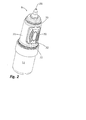
たとえ媒体貯蔵器12内の媒体の蒸発が述べたフィルターユニット34のために減少されるとしても、それでもなお媒体貯蔵器12内の媒体の蒸発をさらに減少することが望ましい。そうするために、図3に示されたキャップ60が設けられる。キャップ60は下方の主として円筒状部分62及びそれに隣接した上方の円錐形部分64を持つ。排出開口66が円錐形部分64の領域内に設けられる。
Even if the evaporation of the media in the
キャップ60は図1と2の分配装置8上に図4に示された態様で押付けられることができる。キャップ60の形状はここでは、特に図2に示された二つの全周接触路70,72においてキャップ60がハウジング10と接触するようにハウジング10の形状に適合される。接触路70と72の間では、ハウジング10とキャップ60の円筒状部分62は互いに離れており、接触路70,72により周囲雰囲気から気密に閉鎖されている中間空間80を共同して限定する。
The
ハウジング10に対してのキャップ60の要求される低配置精度を達成するために、接触路70,72はキャップ60とハウジング10の略円筒状領域の領域内に設けられる。これは、キャップ60とハウジング10の間の全周接触が既に二つの接触路70,72の一つに存在するときであっても、キャップ60が著しく高い力を及ぼされることなくハウジング10上にさらに押付けられることができ、従って全周接触が第二接触路でもまた達成される。
In order to achieve the required low placement accuracy of the
図4に示されたキャップ60の取付け状態では、この環状空間80中に開口する入口間隙32の完全な封止は接触路70,72及びそれにより形成された全周環状空間80により達成される。従って、媒体の無視できるほどに小さな割合のみが、たとえ分配装置が長期間貯蔵されるとしても媒体貯蔵器12から逃げる。
In the mounted state of the
入口開口32を気密に閉鎖することが望ましいけれども、本分配装置では出口開口26に関してはこれは望ましくない。出口開口26は媒体の蒸発に対して出口弁24により十分に保護されている。しかし、もし分配操作後に出口開口26の領域内にまだ残る媒体が、キャップ60が既に取付けられているときであっても乾燥できるなら有利である。この目的のため、既述の排出開口66がキャップ60の円錐形部分64内に設けられる。それらは空気交換、従って出口開口26の迅速な乾燥を可能にする。しかし、接触路70のおかげで、排出開口66を持つこの設計は入口開口32の気密設計のどのような損失も伴なわない。
Although it is desirable to hermetically close the
Claims (4)
− ハウジング(10)、
− 媒体貯蔵器(12)、
− 媒体を分配するための出口開口(26)及び
− 媒体貯蔵器(12)内の容積均等化の目的のための空気取入れのための入口開口(32)、
を含み、さらに
− ハウジング(10)上に取付け可能でありかつ取付け状態のときに出口開口(26)を保護するキャップ(60)が設けられている、ものにおいて、
キャップ(60)が、一方では周囲雰囲気からかつ他方では出口開口(26)から気密態様で入口開口(32)を閉鎖すること、及び入口開口(32)が、ハウジングに対して可動な作動ボタン(30)の領域内に設けられ、作動ボタン(30)とハウジング(10)との間の入口間隙(32)として設計されていることを特徴とする分配装置。 A dispensing device (8) for dispensing a liquid medium,
-Housing (10),
-Medium reservoir (12),
An outlet opening (26) for distributing the medium and an inlet opening (32) for intake of air for the purpose of volume equalization in the medium reservoir (12),
A cap (60) is provided that is mountable on the housing (10) and that protects the outlet opening (26) when mounted;
Cap (60), while closing the inlet opening (32) in a gastight manner from the outlet opening (26) in and the other from the ambient atmosphere, and the inlet opening (32) is movable actuating button relative to the housing ( 30) Dispensing device provided in the region of 30) and designed as an inlet gap (32) between the actuating button (30) and the housing (10).
Applications Claiming Priority (2)
| Application Number | Priority Date | Filing Date | Title |
|---|---|---|---|
| DE102009006430A DE102009006430A1 (en) | 2009-01-23 | 2009-01-23 | discharge |
| DE102009006430.3 | 2009-01-23 |
Publications (2)
| Publication Number | Publication Date |
|---|---|
| JP2010168119A JP2010168119A (en) | 2010-08-05 |
| JP5390420B2 true JP5390420B2 (en) | 2014-01-15 |
Family
ID=42101310
Family Applications (1)
| Application Number | Title | Priority Date | Filing Date |
|---|---|---|---|
| JP2010008114A Active JP5390420B2 (en) | 2009-01-23 | 2010-01-18 | Dispensing device |
Country Status (4)
| Country | Link |
|---|---|
| US (1) | US8292129B2 (en) |
| EP (1) | EP2210674B1 (en) |
| JP (1) | JP5390420B2 (en) |
| DE (1) | DE102009006430A1 (en) |
Families Citing this family (14)
| Publication number | Priority date | Publication date | Assignee | Title |
|---|---|---|---|---|
| DE102010063587B4 (en) * | 2010-12-20 | 2018-03-15 | Aptar Radolfzell Gmbh | Discharge device for a liquid |
| DE102011007405A1 (en) * | 2011-04-14 | 2012-10-18 | Ing. Erich Pfeiffer Gmbh | Cosmetic dispenser |
| US9205198B2 (en) * | 2012-01-17 | 2015-12-08 | Dr. Py Institute Llc | Multiple dose syringe and method |
| EP4265236A3 (en) | 2012-07-26 | 2023-11-29 | Allergan, Inc. | Dual cap system for container-closures to maintain tip sterility during shelf storage |
| DE102013226250B4 (en) * | 2013-12-17 | 2019-07-18 | Aptar Radolfzell Gmbh | Protective cap for a dispenser and dispenser comprising a dispenser for dispensing pharmaceutical and / or cosmetic liquids |
| DE102016207722A1 (en) * | 2016-05-04 | 2017-11-30 | Aptar Radolfzell Gmbh | liquid dispenser |
| BR112019015308B1 (en) | 2017-02-01 | 2023-09-26 | Silgan Dispensing Systems Hemer Gmbh | DISPENSER FOR ONE LIQUID |
| EP3427840B1 (en) | 2017-07-13 | 2020-12-02 | Aptar Radolfzell GmbH | Liquid dispenser |
| JP7254074B2 (en) | 2017-11-02 | 2023-04-07 | エフ・ホフマン-ラ・ロシュ・アクチェンゲゼルシャフト | Droplet dispensing device and system |
| USD888552S1 (en) * | 2018-06-29 | 2020-06-30 | Aptar Radolfzell Gmbh | Dispenser cap |
| USD909204S1 (en) * | 2018-06-29 | 2021-02-02 | Aptar Radolfzell Gmbh | Spraying device for bottles |
| USD882412S1 (en) * | 2018-07-10 | 2020-04-28 | Aptar Radolfzell Gmbh | Packaging bottle for liquids |
| USD889278S1 (en) * | 2018-12-28 | 2020-07-07 | Aptar Radolfzell Gmbh | Packaging bottle for liquids |
| EP3730220B1 (en) * | 2019-04-26 | 2022-07-06 | Aptar Radolfzell GmbH | Dispenser for discharging liquids |
Family Cites Families (37)
| Publication number | Priority date | Publication date | Assignee | Title |
|---|---|---|---|---|
| US3221945A (en) * | 1965-04-02 | 1965-12-07 | Jr George B Davis | Fluid dispenser |
| GB1402638A (en) * | 1972-06-27 | 1975-08-13 | Allen & Hanburys Ltd | Device for dispensing medicaments from a pressurised dispensing container |
| JPS55373Y2 (en) * | 1974-09-26 | 1980-01-08 | ||
| US4413753A (en) * | 1980-05-15 | 1983-11-08 | Pacer Technology And Resources, Inc. | Dispenser for cyanoacrylate adhesives |
| DE3820184A1 (en) * | 1988-06-14 | 1989-12-21 | Schwan Stabilo Schwanhaeusser | APPLICATION DEVICE FOR A VISCOSE, PREFERABLY COSMETIC MASS |
| US4883471A (en) * | 1988-08-16 | 1989-11-28 | Braginetz Paul A | Disposable shielded medical syringe |
| AU663879B2 (en) * | 1991-07-02 | 1995-10-26 | Otto Katz | Dispenser of doses of liquids and paste-like masses |
| DE4128295A1 (en) * | 1991-08-27 | 1993-03-04 | Pfeiffer Erich Gmbh & Co Kg | DISCHARGE DEVICE FOR FLOWABLE MEDIA |
| US5373972A (en) * | 1991-11-15 | 1994-12-20 | Jsp Partners, L.P. | Preservative-free sterile fluid dispensing system |
| SE9201718D0 (en) * | 1992-06-03 | 1992-06-03 | Astra Ab | NASAL SPRAY DEVICE |
| US6000580A (en) * | 1992-06-03 | 1999-12-14 | Astra Aktielbolag | Device for dispensing preservative-free nasal sprays and similar preparations |
| FR2721285B1 (en) * | 1994-06-20 | 1996-08-02 | Oreal | Manual precompression pump for spraying a liquid and distribution assembly equipped with such a pump. |
| FR2727162B1 (en) * | 1994-11-23 | 1996-12-20 | Oreal | MANUAL PREPRESSURE PUMP FOR SPRAYING A LIQUID AND DISPENSING ASSEMBLY PROVIDED WITH SUCH A PUMP |
| FR2740431B1 (en) * | 1995-10-30 | 1997-12-12 | Sofab | PERMEABLE WALL LIQUID DISPENSING BOTTLE |
| DE19613185A1 (en) | 1996-04-02 | 1997-10-09 | Pfeiffer Erich Gmbh & Co Kg | Dosing device for flowable media such as powder / air dispersions |
| US5829640A (en) * | 1996-09-06 | 1998-11-03 | The Procter & Gamble Company | Dispensing pump |
| DE10015968A1 (en) * | 2000-03-30 | 2001-10-04 | Pfeiffer Erich Gmbh & Co Kg | Media Donor |
| DE10032976A1 (en) * | 2000-07-06 | 2002-01-17 | Pfeiffer Erich Gmbh & Co Kg | Discharge device for media |
| DE10049898C2 (en) * | 2000-10-10 | 2002-10-02 | Steven Padar | Dispenser for fluids |
| US7275665B2 (en) * | 2000-12-14 | 2007-10-02 | Young John L | Vented fluid closure and container |
| JP4749572B2 (en) * | 2001-03-13 | 2011-08-17 | 大成化工株式会社 | Dispensing container plug structure |
| WO2003026803A1 (en) * | 2001-09-21 | 2003-04-03 | Ing. Erich Pfeiffer Gmbh | Dosing device with a pump device |
| GB0125702D0 (en) * | 2001-10-26 | 2001-12-19 | Scopenext Ltd | Dispenser pump |
| JP4001364B2 (en) * | 2002-04-30 | 2007-10-31 | 株式会社吉野工業所 | Dispensing container |
| DE10231749B4 (en) * | 2002-07-13 | 2004-07-29 | Aero Pump GmbH, Zerstäuberpumpen | Suction-pressure pump for dispensing a liquid from a container |
| DE102005009295A1 (en) * | 2004-07-13 | 2006-02-16 | Ing. Erich Pfeiffer Gmbh | Dosing device for media |
| DE102004044344A1 (en) * | 2004-09-09 | 2006-03-30 | Ing. Erich Pfeiffer Gmbh | metering |
| JP4738842B2 (en) * | 2005-02-28 | 2011-08-03 | 株式会社吉野工業所 | Dispensing container |
| DE202005019298U1 (en) * | 2005-08-01 | 2006-12-07 | Megaplast Gmbh & Co. Kg | Dispenser for portioned issue |
| EP1779933A1 (en) * | 2005-10-26 | 2007-05-02 | The Procter and Gamble Company | Dispenser for a liquid |
| US7726520B2 (en) * | 2005-12-22 | 2010-06-01 | Innopak Inc. | Metered dispenser with feed-containing piston drive mechanism |
| EP1974825B1 (en) * | 2006-01-26 | 2013-05-08 | Mitani Valve Co., Ltd. | Content discharge mechanism for pump-type container and pump-type product with content discharge mechanism |
| EP1834705B1 (en) * | 2006-03-13 | 2011-09-14 | Ing. Erich Pfeiffer GmbH | Discharge device for a flowable medium |
| CN2937092Y (en) * | 2006-08-02 | 2007-08-22 | 袁建军 | Liquid dispenser |
| WO2008061041A2 (en) * | 2006-11-11 | 2008-05-22 | Medical Instill Technologies, Inc. | Multiple dose delivery device with manually depressible actuator and one-way valve for storing and dispensing substances, and related method |
| US7628298B2 (en) * | 2007-02-28 | 2009-12-08 | Berry Plastics Corporation | Aerosol overcap with evaporation vent |
| DE102007016503A1 (en) * | 2007-03-26 | 2008-10-02 | Ing. Erich Pfeiffer Gmbh | Discharge device for media |
-
2009
- 2009-01-23 DE DE102009006430A patent/DE102009006430A1/en not_active Ceased
- 2009-12-18 EP EP09015671.2A patent/EP2210674B1/en active Active
-
2010
- 2010-01-13 US US12/657,081 patent/US8292129B2/en active Active
- 2010-01-18 JP JP2010008114A patent/JP5390420B2/en active Active
Also Published As
| Publication number | Publication date |
|---|---|
| EP2210674A3 (en) | 2011-05-18 |
| EP2210674B1 (en) | 2013-06-26 |
| US8292129B2 (en) | 2012-10-23 |
| EP2210674A2 (en) | 2010-07-28 |
| JP2010168119A (en) | 2010-08-05 |
| DE102009006430A1 (en) | 2010-07-29 |
| US20100187260A1 (en) | 2010-07-29 |
Similar Documents
| Publication | Publication Date | Title |
|---|---|---|
| JP5390420B2 (en) | Dispensing device | |
| JP6441358B2 (en) | Protective cap for dispenser and release device for releasing pharmaceutical liquid and / or cosmetic liquid | |
| JP6260831B2 (en) | Pumping cosmetic container | |
| CN106102931B (en) | Liquid delivery and dispensing device comprising a protective cap | |
| JP4778652B2 (en) | Improved fluid dispenser pump and fluid dispenser apparatus having such a pump | |
| JP6247045B2 (en) | Valve controlled dispensing closure | |
| KR101399411B1 (en) | Gas exhausting device for airtight container | |
| JP2012035489A5 (en) | Liquid container, sealing member, and cap | |
| US9700907B2 (en) | Discharging device | |
| JP2013512390A5 (en) | ||
| JP2011240686A5 (en) | ||
| JP2015117015A5 (en) | ||
| JP2002206480A5 (en) | ||
| JP4953417B2 (en) | Air dryer | |
| TW201402427A (en) | Substrate housing container minimizing intrusion of dust | |
| WO2023098827A1 (en) | Pressure relief device, battery pack, and vehicle | |
| JP2015523179A5 (en) | ||
| JP2010115216A (en) | Powder cosmetic material container | |
| KR101707120B1 (en) | Pumping type cosmetic vessel having a side button | |
| JP5393842B2 (en) | Sealed container seal structure | |
| JP7460341B2 (en) | Container structure and waste liquid reservoir | |
| IT201800006050A1 (en) | DEVICE FOR THE STORAGE AND DISPENSING OF COFFEE BEANS | |
| KR20220003103A (en) | a liquid dispenser comprising a discharge head and a discharge head | |
| US7596978B2 (en) | Blasting device | |
| KR20130000272A (en) | Liquid cosmetic containers |
Legal Events
| Date | Code | Title | Description |
|---|---|---|---|
| A621 | Written request for application examination |
Free format text: JAPANESE INTERMEDIATE CODE: A621 Effective date: 20120815 |
|
| A977 | Report on retrieval |
Free format text: JAPANESE INTERMEDIATE CODE: A971007 Effective date: 20130617 |
|
| A131 | Notification of reasons for refusal |
Free format text: JAPANESE INTERMEDIATE CODE: A131 Effective date: 20130628 |
|
| A521 | Request for written amendment filed |
Free format text: JAPANESE INTERMEDIATE CODE: A523 Effective date: 20130828 |
|
| TRDD | Decision of grant or rejection written | ||
| A01 | Written decision to grant a patent or to grant a registration (utility model) |
Free format text: JAPANESE INTERMEDIATE CODE: A01 Effective date: 20131004 |
|
| A61 | First payment of annual fees (during grant procedure) |
Free format text: JAPANESE INTERMEDIATE CODE: A61 Effective date: 20131010 |
|
| R150 | Certificate of patent or registration of utility model |
Ref document number: 5390420 Country of ref document: JP Free format text: JAPANESE INTERMEDIATE CODE: R150 Free format text: JAPANESE INTERMEDIATE CODE: R150 |
|
| R250 | Receipt of annual fees |
Free format text: JAPANESE INTERMEDIATE CODE: R250 |
|
| R250 | Receipt of annual fees |
Free format text: JAPANESE INTERMEDIATE CODE: R250 |
|
| R250 | Receipt of annual fees |
Free format text: JAPANESE INTERMEDIATE CODE: R250 |
|
| R250 | Receipt of annual fees |
Free format text: JAPANESE INTERMEDIATE CODE: R250 |
|
| R250 | Receipt of annual fees |
Free format text: JAPANESE INTERMEDIATE CODE: R250 |
|
| R250 | Receipt of annual fees |
Free format text: JAPANESE INTERMEDIATE CODE: R250 |
|
| R250 | Receipt of annual fees |
Free format text: JAPANESE INTERMEDIATE CODE: R250 |
|
| R250 | Receipt of annual fees |
Free format text: JAPANESE INTERMEDIATE CODE: R250 |