JP5387986B2 - Casting line and sand removal method - Google Patents
Casting line and sand removal method Download PDFInfo
- Publication number
- JP5387986B2 JP5387986B2 JP2010191100A JP2010191100A JP5387986B2 JP 5387986 B2 JP5387986 B2 JP 5387986B2 JP 2010191100 A JP2010191100 A JP 2010191100A JP 2010191100 A JP2010191100 A JP 2010191100A JP 5387986 B2 JP5387986 B2 JP 5387986B2
- Authority
- JP
- Japan
- Prior art keywords
- lattice
- sand
- container
- mold
- casting line
- Prior art date
- Legal status (The legal status is an assumption and is not a legal conclusion. Google has not performed a legal analysis and makes no representation as to the accuracy of the status listed.)
- Active
Links
Images


Landscapes
- Molds, Cores, And Manufacturing Methods Thereof (AREA)
Description
本発明は、鋳造の冷却工程において、鋳型から鋳物砂と鋳物素材とを分ける砂落とし装置を備えた鋳造ラインおよび砂落とし方法に関するものであり、さらに詳細には、格子付き容器を用いた1個流し砂落としの技術に関するものである。 The present invention relates to a casting line and a sand removal method provided with a sand removal device that separates foundry sand and foundry material from a mold in a casting cooling process, and more specifically, one using a container with a lattice. This is related to the technique of casting sand removal.
従来、鋳造の冷却工程において鋳物砂と鋳造された製品とを分離させる方法として、ドラム内に注湯済みの鋳型を投入し、回転や振動と散水により分離させる方法(特許文献1参照)や、鋳造ライン上において搬送される鋳型を振動機上に載せ、振動により解枠・分離させる方法(特許文献2参照)があった。 Conventionally, as a method for separating the foundry sand and the cast product in the casting cooling step, a method in which a poured mold is poured into the drum and separated by rotation, vibration and water spray (see Patent Document 1), There has been a method (see Patent Document 2) in which a mold to be conveyed on a casting line is placed on a vibrator and disassembled and separated by vibration.
しかしながら、特許文献1記載の方法および装置では、ドラム内に多数の鋳型を入れ、1モールド毎の砂落としを行うことができないため、後工程での鋳型毎の個別管理が難しいという問題点があった。
However, the method and apparatus described in
また特許文献2記載の方法および装置では、鋳枠(鋳造枠)からパンチアップされた鋳物素材を内蔵した鋳型は、プッシャーもしくは把持手段によって振動機に移載され、前記振動機の振動によって砂落としされている。次に砂落としされ鋳物砂を分離された鋳物素材は、プッシャーによって押し出され、冷却バスケットに移載される。ここで鋳枠から1つ1つパンチアップされるため、鋳型毎の管理ができるかのように見える。
In the method and apparatus described in
しかしながら、前記振動機の振動によって砂落としされ、冷却バスケットに移載されるまでの間に、何らかの原因で鋳型が前記振動機に取り残され、次に送り込まれた鋳型の鋳物素材とともに、冷却バスケットに移載されることがある。よって、後工程でモールド毎の個別管理ができなくなるという問題点があった。 However, the sand is dropped by the vibration of the vibrator and transferred to the cooling basket. For some reason, the mold is left behind in the vibrator for some reason. May be transferred. Therefore, there has been a problem that individual management for each mold cannot be performed in a later process.
そこで本発明は、叙上の事情に鑑み、注湯後の鋳型において、1モールド毎の砂落としを行うことにより砂落としをした後でも、確実に鋳型毎の個別管理を行うことができる鋳造ライン及び砂落とし方法を提供することを目的とする。 Therefore, in view of the above circumstances, the present invention provides a casting line capable of reliably performing individual management for each mold even after sand removal by performing sand removal for each mold in the mold after pouring. And to provide a sand removal method.
上記の課題を解決するためになされた本発明の鋳造ラインは、注湯済み鋳型を搬送し、該鋳型を搬送する冷却ライン上に砂落し装置を具備する鋳造ラインであって、注湯済み鋳型が1モールドずつ投入され搬送される格子付き容器と、鋳型を格子付き容器から移し換えること無く、格子付き容器ごと振動させて素材と鋳物砂を分離するシェイクアウトマシンとを具備したことを特徴とするものである。 The casting line of the present invention made to solve the above problems is a casting line that transports a poured mold, and includes a sand removal device on a cooling line that transports the casting mold. Characterized in that it comprises: a container with a lattice that is fed and conveyed one by one; and a shakeout machine that vibrates the entire container with the lattice without separating the mold from the container with the lattice to separate the material from the foundry sand. To do.
なお請求項2のように、格子付き容器を搬送するローラコンベヤの直下に、昇降機能付きシェイクアウトマシンを1台、または複数台配置することが好ましい。また請求項3のように、シェイクアウトマシン上部の砂抜き位置に、昇降できる鋳型破砕用櫛刃を設けることが好ましい。また請求項4のように、格子付き容器を格子パレットとしたり、請求項5のように、格子付き容器を底面格子付き受け箱とすることができる。また請求項6のように、格子パレットの側面からの素材のはみ出し、落下を防止するための昇降できる衝立を具備することが好ましい。
As in
さらに本発明の砂落とし方法は、注湯済み鋳型を1モールドずつ格子付き容器に投入してローラコンベヤ上を搬送する工程と、ローラコンベヤの下方からシェイクアウトマシンを上昇し、格子付き容器をローラコンベヤ上からシェイクアウトマシン上に移し換えて砂落としを行う工程と、を含むことを特徴とするものである。 Furthermore, the sand dropping method of the present invention includes a step in which poured molds are poured one by one into a container with a lattice and conveyed on a roller conveyor, and a shakeout machine is lifted from below the roller conveyor to remove the container with a lattice And transferring the sand from the conveyor onto a shake-out machine to remove sand.
本発明によれば、鋳型は格子付き容器から移し変えられることなく、格子付き容器ごと振動させて素材と鋳物砂との分離が行われるので、1モールド毎の砂落としを行うことにより砂落としをした後でも、確実に鋳型毎の個別管理を行うことができる According to the present invention, the mold is not transferred from the container with the lattice, and the container with the lattice is vibrated to separate the material from the foundry sand. Therefore, the sand removal is performed by removing the sand for each mold. Even after it is done, individual management for each mold can be performed reliably.
以下に本発明の実施形態を説明する。
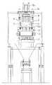
図1、図2は鋳造ラインのうち、注湯済みの鋳型を搬送する冷却ラインの全体図であり、1は格子付き容器、6は格子付き容器1を搬送するローラコンベヤである。この実施形態では格子付き容器1は格子パレット(定盤)1aである。格子パレット1aは図9に示されるように四角形のパレットに多数の砂落とし用の貫通孔1cを形成したもので、この実施形態では各貫通孔1cは平行に形成されている。
Embodiments of the present invention will be described below.
FIG. 1 and FIG. 2 are general views of a cooling line for conveying a poured mold in a casting line, wherein 1 is a container with a lattice, and 6 is a roller conveyor for conveying the
2は注湯済み鋳型であり、図示しない解枠装置から1モールドずつ格子パレット1a上に投入される。注湯済み鋳型2が載せられた格子パレット1aは、ローラコンベヤ6上を図1に矢印で示す右方向に向かって搬送される。
格子付き容器1を搬送するローラコンベヤ6の直下には、昇降機能7を備えたシェイクアウトマシン3が1台または複数台配置されている。この実施形態では3台のシェイクアウトマシン3が等間隔で配置されている。このようにシェイクアウトマシン3を複数台設置しておけば、タイムサイクルが短いラインに対しても、タイムサイクルに影響を受ける事無く、砂落とし時間を確保する事が可能となる。
One or a plurality of shake-out
図3と図4はシェイクアウトマシン3が下降位置にある状態を示し、図5と図6はシェイクアウトマシン3が昇降機能7によって上昇した状態を示す。図4に示されるように、シェイクアウトマシン3が下降位置にあるときには格子パレット1aはローラコンベヤ6上に支持されているが、図6に示す上昇位置にあるときには格子パレット1aはシェイクアウトマシン3の上部突起によってローラコンベヤ6から僅かに持ち上げられる。このため、注湯済み鋳型2が載せられた格子パレット1aはそのままシェイクアウトマシン3上に載せられ、振動により素材4と鋳物砂5とが分離される。鋳物砂5は砂落とし用の貫通孔1cから下方に落下し、素材4はローラコンベヤ6により次工程に搬送される。
3 and 4 show a state in which the
このように本発明においては鋳型は格子付き容器1から移し変えられることなく、格子付き容器1ごと振動させて素材4と鋳物砂5とを分離するので、1モールド毎の砂落としを行うことにより砂落としをした後でも、確実に鋳型毎の個別管理を行うことができる利点がある。
As described above, in the present invention, the mold is not transferred from the
しかしローラコンベヤ6上に砂抜け性が悪い未注湯鋳型が混在している場合には、シェイクアウトマシン3により振動を加えても鋳物砂5を破砕できないおそれがある。そこで図7、図8に示すように、シェイクアウトマシン3の上部の砂抜き位置に、昇降できる鋳型破砕用櫛刃8を設けてある。鋳型破砕用櫛刃8は上部の昇降機構8aによって昇降し、シェイクアウトマシン3によっては破砕できない未注湯鋳型などの鋳型を確実に破砕する。
However, when there is a mixture of unpoured molds with poor sand removal properties on the
また格子付き容器1としてこのような格子パレット1aを使用する場合、格子パレット1aの側面から素材4や鋳物砂5がはみ出したり、落下したりすることがある。そこで図5、図6に示すように、昇降機構9aにより昇降できる衝立9を設けておき、素材4や鋳物砂5がはみ出したり、落下したりことを防止することが好ましい。この昇降できる衝立9は、シェイクアウトマシン3上に、砂落とし前の格子パレット(定盤)1aが搬入された後、砂落としのためにシェイクアウトマシン3を上昇させる前に下降させる。また、砂落とし後、シェイクアウトマシン3を下降させた後に、図3、4のように上昇させるものとする。
Moreover, when using such a
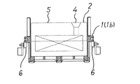
図12〜図16に、格子付き容器1として底面格子付き受け箱1bを使用した実施形態を示す。底面格子付き受け箱1bは周囲に垂直壁を備え、底面を格子パレット1aと同様の格子状としたものである。格子パレット(定盤)1a方式の場合には、素材4の冷却効果が大きいと言う長所がある反面、砂落とし中の素材4、鋳物砂5のはみ出し、落下、および搬送中の格子パレット1aからの砂こぼれが多いという短所がある。これに対して、底面格子付き受け箱1b方式の場合、素材4の冷却効果が小さいと言う短所がある反面、砂落とし中の素材4、鋳物砂5のはみ出し、落下、および搬送中の底面格子付き受け箱1bからの砂こぼれを低減できると言う長所がある。
12 to 16 show an embodiment in which a receiving box 1b with a bottom grid is used as the
従って底面格子付き受け箱1bを用いた場合には昇降できる衝立9は不要であるが、昇降できる鋳型破砕用櫛刃8は格子パレット1aを用いた場合と同様に設け、シェイクアウトマシン3によっては破砕できない鋳型を確実に破砕することが好ましい。
Therefore, when using the receiving box 1b with the bottom grid, the
以上のように、本発明によれば、1つの受け箱に1つの鋳型を入れ、その受け箱をシェイクアウトマシン3によって振動させ砂落としを行うことで、1モールドずつ砂落としすることができるので、鋳物砂と鋳物素材の分離後も、鋳型毎の個別管理をすることができる。またシェイクアウトマシン3はローラコンベヤ6の直下に配置するため、昇降式シェイクアウトマシンの複数台持ちが容易であり、タイムサイクルが短いラインに対しても、タイムサイクルに影響を受ける事無く、砂落とし時間を確保する事ができる。
As described above, according to the present invention, it is possible to drop sand by one mold by putting one mold into one receiving box and vibrating the receiving box by the shake-out
1 格子付き容器
1a 格子パレット(定盤)
1b 底面格子付き受け箱
1c 貫通孔
2 鋳型
3 シェイクアウトマシン
4 素材
5 鋳物砂
6 ローラコンベヤ
7 昇降機能
8 昇降できる鋳型破砕用櫛刃
8a 昇降機構
9 昇降できる衝立
9a 昇降機構
1 Container with
1b Receiving box with
Claims (7)
注湯済み鋳型が1モールドずつ投入され搬送される格子付き容器と、
鋳型を格子付き容器から移し換えること無く、格子付き容器ごと振動させて素材と鋳物砂を分離するシェイクアウトマシンとを具備したことを特徴とする鋳造ライン。 A casting line that transports a poured mold, and includes a sand removal device on a cooling line that transports the mold,
A latticed container in which poured molds are poured and conveyed one by one;
A casting line comprising a shake-out machine that vibrates the entire container with the lattice without separating the mold from the container with the lattice to separate the material and the foundry sand.
ローラコンベヤの下方からシェイクアウトマシンを上昇し、格子付き容器をローラコンベヤ上からシェイクアウトマシン上に移し換えて砂落としを行う工程と、
を含むことを特徴とする砂落とし方法。 A process in which poured molds are poured one by one into a container with a lattice and conveyed on a roller conveyor;
The process of raising the shakeout machine from below the roller conveyor, transferring the latticed container from the roller conveyor onto the shakeout machine, and removing sand,
Sand removal method characterized by including.
Priority Applications (1)
| Application Number | Priority Date | Filing Date | Title |
|---|---|---|---|
| JP2010191100A JP5387986B2 (en) | 2010-08-27 | 2010-08-27 | Casting line and sand removal method |
Applications Claiming Priority (1)
| Application Number | Priority Date | Filing Date | Title |
|---|---|---|---|
| JP2010191100A JP5387986B2 (en) | 2010-08-27 | 2010-08-27 | Casting line and sand removal method |
Publications (2)
| Publication Number | Publication Date |
|---|---|
| JP2012045593A JP2012045593A (en) | 2012-03-08 |
| JP5387986B2 true JP5387986B2 (en) | 2014-01-15 |
Family
ID=45901093
Family Applications (1)
| Application Number | Title | Priority Date | Filing Date |
|---|---|---|---|
| JP2010191100A Active JP5387986B2 (en) | 2010-08-27 | 2010-08-27 | Casting line and sand removal method |
Country Status (1)
| Country | Link |
|---|---|
| JP (1) | JP5387986B2 (en) |
Families Citing this family (2)
| Publication number | Priority date | Publication date | Assignee | Title |
|---|---|---|---|---|
| CN113941701A (en) * | 2020-07-17 | 2022-01-18 | 溧阳市联华机械制造有限公司 | Automatic shakeout system of many varieties sand box based on RFID |
| CN112122589A (en) * | 2020-09-17 | 2020-12-25 | 繁昌县琪鑫铸造有限公司 | Shakeout machine for sand casting |
Family Cites Families (4)
| Publication number | Priority date | Publication date | Assignee | Title |
|---|---|---|---|---|
| JPH0523832A (en) * | 1991-07-16 | 1993-02-02 | Shinko Electric Co Ltd | Apparatus for shaking out sand from casting |
| JPH05138332A (en) * | 1991-11-22 | 1993-06-01 | Komatsu Ltd | Device and method for spraying water in drum shaker |
| JP4052816B2 (en) * | 2001-06-25 | 2008-02-27 | ダイハツ工業株式会社 | Unpacking device in casting line |
| JP4386882B2 (en) * | 2005-11-01 | 2009-12-16 | ダイハツ工業株式会社 | Cast product sand removal method and cast product sand removal device |
-
2010
- 2010-08-27 JP JP2010191100A patent/JP5387986B2/en active Active
Also Published As
| Publication number | Publication date |
|---|---|
| JP2012045593A (en) | 2012-03-08 |
Similar Documents
| Publication | Publication Date | Title |
|---|---|---|
| JP5403403B2 (en) | Casting line and sand removal method | |
| KR20170036808A (en) | Method and device for unpacking a component | |
| JP5387986B2 (en) | Casting line and sand removal method | |
| CN103842114A (en) | Universal-flask separating device for mold and universal-flask separating method for mold using same | |
| JP5246224B2 (en) | Casting line and sand removal method | |
| JP6350244B2 (en) | Mold separation method and apparatus | |
| WO2010125845A1 (en) | Method of manufacturing cast metal products, and manufacturing plant | |
| CN202667621U (en) | Waste material stop plate device for casting machine | |
| JP4052816B2 (en) | Unpacking device in casting line | |
| CN102380609B (en) | Foundry production line and shakeout method | |
| JP5212843B2 (en) | Casting line and sand removal method | |
| JPH11138253A (en) | Shake-out apparatus in casting line | |
| JP4179529B2 (en) | Vibrating sand mold ballast | |
| JPH10244360A (en) | Shakeout machine | |
| JP2004141954A (en) | Method and device for taking out casting blank from flask-attached casting mold | |
| US3411171A (en) | Material handling apparatus | |
| JP2002103020A (en) | Method and apparatus for recovering disagregated molding sand | |
| JP3374379B2 (en) | Sand mold release device with cast flask | |
| CN219073572U (en) | Three-dimensional tealeaves screening system | |
| JP2003025061A (en) | Molding and cooling line for green sand mold | |
| CN108722539A (en) | A kind of Furan Resin-Bonded Sand line vibration crushing regenerating machine | |
| JP6863323B2 (en) | Mold disassembling device | |
| JPH11347710A (en) | Device for separating molding sand in mold after removing flask | |
| CN108145140A (en) | Flask overturning device | |
| JP5617113B2 (en) | Sand sediment residue processing equipment |
Legal Events
| Date | Code | Title | Description |
|---|---|---|---|
| A621 | Written request for application examination |
Free format text: JAPANESE INTERMEDIATE CODE: A621 Effective date: 20120723 |
|
| A977 | Report on retrieval |
Free format text: JAPANESE INTERMEDIATE CODE: A971007 Effective date: 20130904 |
|
| TRDD | Decision of grant or rejection written | ||
| A01 | Written decision to grant a patent or to grant a registration (utility model) |
Free format text: JAPANESE INTERMEDIATE CODE: A01 Effective date: 20130913 |
|
| A61 | First payment of annual fees (during grant procedure) |
Free format text: JAPANESE INTERMEDIATE CODE: A61 Effective date: 20130926 |
|
| R150 | Certificate of patent or registration of utility model |
Ref document number: 5387986 Country of ref document: JP Free format text: JAPANESE INTERMEDIATE CODE: R150 Free format text: JAPANESE INTERMEDIATE CODE: R150 |
|
| R250 | Receipt of annual fees |
Free format text: JAPANESE INTERMEDIATE CODE: R250 |