JP5384386B2 - Game machine - Google Patents
Game machine Download PDFInfo
- Publication number
- JP5384386B2 JP5384386B2 JP2010020272A JP2010020272A JP5384386B2 JP 5384386 B2 JP5384386 B2 JP 5384386B2 JP 2010020272 A JP2010020272 A JP 2010020272A JP 2010020272 A JP2010020272 A JP 2010020272A JP 5384386 B2 JP5384386 B2 JP 5384386B2
- Authority
- JP
- Japan
- Prior art keywords
- display
- special
- game
- variable display
- effect
- Prior art date
- Legal status (The legal status is an assumption and is not a legal conclusion. Google has not performed a legal analysis and makes no representation as to the accuracy of the status listed.)
- Expired - Fee Related
Links
Images


Description
本発明は、始動条件の成立にもとづいて、各々を識別可能な複数種類の識別情報の可変表示を行う可変表示手段を備え、前記可変表示手段に表示結果を導出することで遊技の結果を確定し、遊技の結果が特定遊技結果となったときに遊技者にとって有利な特定遊技状態に移行させる遊技機に関する。 The present invention has variable display means for variably displaying a plurality of types of identification information that can be identified based on the establishment of the starting condition, and the game result is determined by deriving the display result to the variable display means. In addition, the present invention relates to a gaming machine that shifts to a specific gaming state that is advantageous to the player when the game result is a specific gaming result.
遊技機として、遊技媒体である遊技球を発射装置によって遊技領域に発射し、遊技領域に設けられている入賞口などの入賞領域に遊技球が入賞すると、所定個の賞球が遊技者に払い出されるものがある。さらに、識別情報を可変表示(「変動」ともいう。)可能な可変表示部が設けられ、可変表示部において識別情報の可変表示の表示結果が特定表示結果となった場合に、所定の遊技価値を遊技者に与えるように構成されたものがある。 As a gaming machine, a game ball, which is a game medium, is launched into a game area by a launching device, and when a game ball wins a prize area such as a prize opening provided in the game area, a predetermined number of prize balls are paid out to the player. There is something to be done. Further, a variable display unit capable of variably displaying the identification information (also referred to as “fluctuation”) is provided, and a predetermined game value is obtained when the display result of the variable display of the identification information in the variable display unit becomes a specific display result. Are configured to give the player.
なお、遊技価値とは、遊技機の遊技領域に設けられた可変入賞球装置の状態が打球が入賞しやすい遊技者にとって有利な状態になることや、遊技者にとって有利な状態になるための権利を発生させたりすることや、賞球払出の条件が成立しやすくなる状態になることである。 The game value is the right that the state of the variable winning ball apparatus provided in the gaming area of the gaming machine becomes advantageous for a player who is easy to win, and the right for becoming advantageous for a player. In other words, or a condition for winning a prize ball is easily established.
パチンコ遊技機では、始動入賞口に遊技球が入賞したことにもとづいて可変表示部において開始される特別図柄(識別情報)の可変表示の表示結果として、あらかじめ定められた特定の表示態様が導出表示された場合に、「大当り」が発生する。なお、導出表示とは、図柄を停止表示させることである(いわゆる再変動の前の停止を除く。)。大当りが発生すると、例えば、大入賞口が所定回数開放して打球が入賞しやすい大当り遊技状態に移行する。そして、各開放期間において、所定個(例えば10個)の大入賞口への入賞があると大入賞口は閉成する。そして、大入賞口の開放回数は、所定回数(例えば15ラウンド)に固定されている。なお、各開放について開放時間(例えば29秒)が決められ、入賞数が所定個に達しなくても開放時間が経過すると大入賞口は閉成する。以下、各々の大入賞口の開放期間をラウンドということがある。 In a pachinko machine, a specific display mode determined in advance is derived and displayed as a display result of variable display of a special symbol (identification information) that is started in the variable display unit based on the winning of a game ball at the start winning opening. If this happens, a “big hit” will occur. Note that the derivation display is to stop and display a symbol (excluding stop before so-called re-variation). When the big hit occurs, for example, the big winning opening is opened a predetermined number of times, and the game shifts to a big hit gaming state where the hit ball is easy to win. And in each open period, if there is a prize for a predetermined number (for example, 10) of the big prize opening, the big prize opening is closed. And the number of times the special winning opening is opened is fixed to a predetermined number (for example, 15 rounds). An opening time (for example, 29 seconds) is determined for each opening, and even if the number of winnings does not reach a predetermined number, the big winning opening is closed when the opening time elapses. Hereinafter, the opening period of each special winning opening may be referred to as a round.
また、可変表示部において、最終停止図柄(例えば左右中図柄のうち中図柄)となる図柄以外の図柄が、所定時間継続して、特定の表示結果と一致している状態で停止、揺動、拡大縮小もしくは変形している状態、または、複数の図柄が同一図柄で同期して変動したり、表示図柄の位置が入れ替わっていたりして、最終結果が表示される前で大当り発生の可能性が継続している状態(以下、これらの状態をリーチ状態という。)において行われる演出をリーチ演出という。また、リーチ状態やその様子をリーチ態様という。さらに、リーチ演出を含む可変表示をリーチ可変表示という。そして、可変表示装置に変動表示される図柄の表示結果が特定の表示結果でない場合には「はずれ」となり、変動表示状態は終了する。遊技者は、大当りをいかにして発生させるかを楽しみつつ遊技を行う。 In the variable display section, the symbols other than the symbol that becomes the final stop symbol (for example, the middle symbol of the left and right middle symbols) continue for a predetermined time and stop, swing, There is a possibility that a big hit will occur before the final result is displayed due to the state of scaling or deformation, or multiple symbols changing synchronously with the same symbol, or the position of the display symbol being switched An effect performed in a continuing state (hereinafter, these states are referred to as reach states) is referred to as reach effect. Further, the reach state and its state are referred to as a reach mode. Furthermore, variable display including reach production is called reach variable display. Then, when the display result of the symbol variably displayed on the variable display device is not a specific display result, it becomes “out of” and the variability display state ends. A player plays a game while enjoying how to generate a big hit.
この種の遊技機は、一般的に、所定の始動入賞口に始動入賞したことにもとづいて、図柄の可変表示を行う権利を所定の上限数(例えば4)を限度として記憶され、変動表示の終了後にその保留記憶数分の変動表示が行われる。保留記憶数は、例えば遊技者から視認可能に設けられた複数の表示部からなる保留表示部にて常に表示され、変動表示の保留記憶数に応じて表示態様が更新されるようになっている。 In general, this type of gaming machine stores a right to perform variable display of symbols up to a predetermined upper limit number (for example, 4) based on the fact that it has started at a predetermined start winning opening, After the end, the change display for the number of reserved storage is performed. The number of reserved memories is always displayed, for example, on a reserved display unit made up of a plurality of display units provided so as to be visible to the player, and the display mode is updated in accordance with the number of reserved stored variable displays. .
そしてこの種の遊技機において、保留表示部を開閉可能に設けられた可動物(いわゆる役物等)を備え、保留表示部に表示される保留記憶数を可動物により隠蔽して保留記憶数を確認できないようにすることで、変動表示の実行に対する意外性を持たせようとしたものがあった(例えば、特許文献1参照)。 In this type of gaming machine, the holding display unit is provided with a movable object (so-called an accessory, etc.) provided to be openable and closable, and the reserved memory number displayed on the holding display unit is concealed by the movable object. There has been an attempt to make the display unpredictable so as to give unexpectedness to the execution of the variable display (see, for example, Patent Document 1).
しかしながら、上記特許文献1では、可動物により保留表示部を隠蔽する場合、全ての表示部が隠蔽されればよいが、例えば4つ表示部のうち2つだけ、といったように部分的に隠蔽することがあると、保留記憶数が2つしかないように遊技者が誤認する虞があり、遊技者に不信感を与えることがあるという問題を有していた。
However, in
本発明は、このような問題点に着目してなされたもので、可動物が可動したときに保留表示領域の表示面側に少なくとも一部が重畳する可能性がある場合に保留記憶された権利の数を遊技者に誤認されることを防止できる遊技機を提供することを目的とする。 The present invention has been made paying attention to such a problem, and when the movable object moves, the right that is reserved and stored when there is a possibility that at least a part thereof may be superimposed on the display surface side of the hold display area. It is an object of the present invention to provide a gaming machine that can prevent a player from misidentifying the number of players.
前記課題を解決するために、本発明の請求項1に記載の遊技機は、
始動条件の成立(普通入賞球装置6Aにより形成される第1始動入賞口に始動入賞したこと。普通可変入賞球装置6Bにより形成される第2始動入賞口に始動入賞したこと)にもとづいて、各々を識別可能な複数種類の識別情報(第1特別図柄、第2特別図柄または飾り図柄)の可変表示を行う可変表示手段(第1特別図柄表示器8a、第2特別図柄表示器8b、画像表示装置5)を備え、前記可変表示手段に表示結果を導出することで遊技の結果を確定し、遊技の結果が特定遊技結果(例えば、大当り遊技結果)となったときに遊技者にとって有利な特定遊技状態に移行させる遊技機(パチンコ遊技機1)であって、
前記始動条件の成立にもとづいて、前記識別情報の可変表示を行う権利を所定の上限数(例えば4)を限度として記憶する保留記憶手段(第1特図保留記憶部151A、第2特図保留記憶部151B、特図保留記憶部195)と、
前記可変表示手段における所定の保留表示領域(画像表示装置5の第1保留記憶数表示エリア5D、第2保留記憶数表示エリア5U)に、所定の保留特定情報を前記保留記憶手段に記憶された権利の数を特定可能に表示する保留表示制御手段(演出制御用CPU120において、保留記憶表示制御処理を実行する部分)と、
前記保留記憶手段(第1特図保留記憶部151A、第2特図保留記憶部151B、特図保留記憶部195)に記憶された1の権利にもとづく前記識別情報(第1特別図柄、第2特別図柄または飾り図柄)の可変表示の表示結果が導出されるまでに、前記遊技の結果を特定遊技結果(例えば、大当り遊技結果)とするか否かを決定する事前決定手段(遊技制御用マイクロコンピュータ100において、ステップS110を実行する部分)と、
前記事前決定手段の決定結果にもとづいて、前記識別情報の可変表示パターンを決定する可変表示パターン決定手段(遊技制御用マイクロコンピュータ100において、ステップS111を実行する部分)と、
前記可変表示パターン決定手段が決定した可変表示パターンを用いて前記識別情報の可変表示を実行する可変表示制御手段(遊技制御用マイクロコンピュータ100において、ステップS112〜113を実行する部分)と、
前記保留記憶手段に1の権利が記憶された後、該1の権利により行われる前記識別情報の可変表示による遊技の結果が前記特定遊技結果となる可能性を予告する先読み予告を、前記1の権利により行われる前記識別情報の可変表示が開始されるまでに実行する予告演出制御手段(演出制御用CPU120が保留表示中止フラグがセットされていないときにステップS921を実行する部分、図45参照)と、
前記可変表示手段における前記保留表示領域に重畳しない非重畳位置(格納位置)から該可変表示手段における前記保留表示領域の少なくとも一部に重畳する重畳位置(前面位置)に可動可能(例えば図56(a)(b)参照)に設けられる可動物(シャッタ38H,38L)と、
前記事前決定手段の決定結果にもとづいて、前記可動物を前記非重畳位置から前記重畳位置に移動させる可動演出を実行するか否かを決定する可動演出決定手段と、
前記可動演出決定手段の決定結果にもとづいて、前記可動演出を実行する可能性を示唆する可動示唆演出を実行する可動示唆演出実行手段と、
前記可動演出決定手段が前記可動演出を実行すると決定したときに、前記可動示唆演出が実行された後に前記可動演出(シャッタ38H,38Lの開閉演出)を実行する可動演出実行手段(演出制御用CPU120において、例えば、ステップS736,737を実行する部分)と、
を備え、
前記予告演出制御手段は、前記先読み予告として、前記保留表示制御手段が表示している保留特定情報の表示態様を変化(通常の丸表示を星表示または菱形表示に変化)させ、
前記可動演出決定手段は、前記事前決定手段によって前記特定遊技結果とすることが決定されているときには、前記特定遊技結果とすることが決定されていないときよりも高い確率で前記可動演出の実行を決定し、
前記保留表示制御手段により、前記可動演出実行手段が前記可動演出を実行しているときには、保留特定情報が消去されるとともに、新たな始動条件の成立にもとづく保留特定情報の表示が禁止され(演出制御用CPU120が保留表示中止フラグがセットされているときにステップS922を実行する部分、図57〜図65参照)、更に、前記可動示唆演出実行手段が前記可動示唆演出を実行しているときには、該可動示唆演出に続いて前記可動演出実行手段が前記可動演出を実行するときも実行しないときにも、保留特定情報が消去されるとともに、新たな始動条件の成立にもとづく保留特定情報の表示が禁止される、
ことを特徴としている。
この特徴によれば、先読み予告として表示されている保留特定情報の表示態様を変化させることで、特定遊技状態への移行に対する遊技者の期待感を高めることができるばかりか、保留表示領域に保留特定情報が表示されている場合に可動演出が実行されるときには、表示されている保留特定情報が消去されるとともに、新たに始動条件が成立しても保留特定情報が表示されることがない。また、保留表示領域に保留特定情報が表示されていない場合に可動演出が実行されるときには、新たに始動条件が成立しても保留特定情報が表示されることがないため、移動してきた可動物により表示中または新たに表示された保留特定情報が部分的に隠蔽されて保留記憶手段に記憶されている権利の数が誤認されることが防止される。また、保留表示領域に保留特定情報が表示されているか否かに関わらず、可動演出が実行されるときには一様に保留特定情報の表示が停止されるため、遊技者に対して不信感を与えることがない。
In order to solve the above-mentioned problem, a gaming machine according to
Based on the establishment of the start condition (starting winning at the first starting winning opening formed by the normal winning
On-hold storage means for storing the right to variably display the identification information based on the establishment of the start condition up to a predetermined upper limit number (for example, 4) (first special figure
Predetermined hold specific information is stored in the hold storage means in a predetermined hold display area (first hold memory
The identification information (first special symbol, second) based on one right stored in the holding storage means (first special figure
Variable display pattern determination means for determining a variable display pattern of the identification information based on the determination result of the prior determination means (the part for executing step S111 in the game control microcomputer 100);
Variable display control means for executing variable display of the identification information using the variable display pattern determined by the variable display pattern determination means (the portion for executing steps S112 to 113 in the game control microcomputer 100);
After the one right is stored in the holding storage means, a pre-reading notice for notifying the possibility that the result of the game by the variable display of the identification information performed by the one right becomes the specific game result, Preliminary effect control means executed until the variable display of the identification information performed according to the right is started (part in which the
It is movable from a non-overlapping position (storage position) that does not overlap the holding display area in the variable display means to a superposition position (front position) that overlaps at least a part of the holding display area in the variable display means (for example, FIG. 56 ( a) (see (b)) a movable object (
Based on the determination result of the pre-determining means, a movable effect determining means for determining whether or not to execute a movable effect for moving the movable object from the non-superimposed position to the superimposed position;
Based on the determination result of the movable effect determining means, the movable suggestion effect executing means for executing the movable suggestion effect suggesting the possibility of executing the movable effect;
When the movable effect determining means determines to execute the movable effect, the movable effect executing means (
With
The notice effect control means changes the display mode of the hold specific information displayed by the hold display control means as the prefetch notice (changes the normal circle display to a star display or a rhombus display),
The movable effect determination means executes the movable effect with a higher probability when the prior determination means determines that the specific game result is determined than when it is not determined that the specific game result is determined. Decide
By the hold display control means, wherein the movable demonstration execution means Rutoki running the movable presentation, hold specific information is erased Rutotomoni, display pending specific information based on establishment of a new start condition is prohibited (Refer to FIG. 57 to FIG. 65, where step S922 is executed when the
It is characterized by that.
According to this feature, by changing the display mode of the hold specific information displayed as the pre-reading notice, not only can the player's expectation for the transition to the specific game state be improved, but the hold display area holds the hold information. When the movable effect is executed when the specific information is displayed, the displayed hold specific information is erased, and the hold specific information is not displayed even if the start condition is newly established. Further, when the movable effect is executed when the hold specific information is not displayed in the hold display area, the hold specific information is not displayed even if the start condition is newly established. This prevents the number of rights stored in the holding storage means from being misidentified by partially hiding the holding specific information being displayed or newly displayed. Further, regardless of whether or not the hold specific information is displayed in the hold display area, the display of the hold specific information is uniformly stopped when the movable effect is executed, so that the player is distrusted. There is nothing.
本発明の手段1に記載の遊技機は、請求項1に記載の遊技機であって、
前記始動条件が成立した旨(普通入賞球装置6Aにより形成される第1始動入賞口に始動入賞したこと。普通可変入賞球装置6Bにより形成される第2始動入賞口に始動入賞したこと)を出音により報知する報知手段(演出制御用CPU120において、ステップS725を実行する部分)を備え、
前記報知手段は、前記保留表示制御手段が表示中の保留特定情報を消去するとともに、新たな始動条件の成立にもとづく保留特定情報の表示を禁止している際に前記始動条件が成立したときに前記報知を行う(演出制御用CPU120において、ステップS903を実行する部分)、
ことを特徴としている。
この特徴によれば、始動条件が成立して保留記憶手段に1の権利が記憶されたことを保留特定情報の目視にて確認できない場合でも、出音により確認することができるため、遊技者に不信感を与えることがない。
A gaming machine according to
The fact that the start condition has been established (start winning prize in the first starting winning opening formed by the normal winning
The notification means erases the hold specific information being displayed by the hold display control means and prohibits the display of the hold specific information based on the establishment of a new start condition when the start condition is satisfied The notification is performed (the portion for executing step S903 in the
It is characterized by that.
According to this feature, even if it is not possible to visually confirm the hold specific information that the start condition is satisfied and that the right of 1 is stored in the hold storage means, it is possible to check by the sound output. There is no distrust.
本発明の手段2に記載の遊技機は、請求項1または手段1に記載の遊技機であって、
前記可変表示手段(第1特別図柄表示器8a、第2特別図柄表示器8b、画像表示装置5)は、
第1始動条件の成立にもとづいて、各々を識別可能な複数種類の第1の識別情報の可変表示を行う第1可変表示手段(第1特別図柄表示器8a、画像表示装置5)と、
第2始動条件の成立にもとづいて、各々を識別可能な複数種類の第2の識別情報の可変表示を行う第2可変表示手段(第2特別図柄表示器8b、画像表示装置5)と、を含み、
前記保留記憶手段は、
前記第1始動条件の成立にもとづいて、前記第1の識別情報の可変表示を行う権利を記憶する第1保留記憶手段(第1特図保留記憶部151A、特図保留記憶部195)と、
前記第2始動条件の成立にもとづいて、前記第2の識別情報の可変表示を行う権利を記憶する第2保留記憶手段(第2特図保留記憶部151B、特図保留記憶部195)と、を含み、
前記保留表示制御手段は、
前記保留表示領域としての第1保留表示領域(画像表示装置5の第1保留記憶数表示エリア5D)に、第1保留特定情報を前記第1保留記憶手段に記憶された権利の数を特定可能に表示するとともに、前記第1保留表示領域とは別個の所定位置に設けられた第2保留表示領域(画像表示装置5の第2保留記憶数表示エリア5U)に、第2保留特定情報を前記第2保留記憶手段に記憶された権利の数を特定可能に表示し、
前記可動物(シャッタ38H,38L)は、
前記第1保留表示領域及び前記第2保留表示領域に重畳しない非重畳位置から前記第1保留表示領域または前記第2保留表示領域の少なくとも一部に重畳する重畳位置に可動可能に設けられ(例えば図56(a)(b)参照)、
前記保留表示制御手段は、前記可動演出実行手段が前記可動演出を実行するときに、表示中の第1保留特定情報及び第2保留特定情報を消去するとともに、新たな第1始動条件の成立にもとづく第1保留特定情報及び新たな第2始動条件の成立にもとづく第2保留特定情報の表示を禁止する(演出制御用CPU120が保留表示中止フラグがセットされているときにステップS922を実行する部分)、
ことを特徴としている。
この特徴によれば、可動物が第1保留表示領域または第2保留表示領域のうち一方に重畳する場合でも、表示されている第1保留特定情報及び第2保留特定情報双方が消去されるとともに、新たに始動条件が成立しても第1保留特定情報または第2保留特定情報が表示されることがないため、第1保留記憶手段及び第2保留記憶手段それぞれに記憶されている権利の数が誤認されることが防止される。
The gaming machine according to means 2 of the present invention is the gaming machine according to
The variable display means (first special symbol display 8a, second special symbol display 8b, image display device 5)
First variable display means (first special symbol display 8a, image display device 5) for performing variable display of a plurality of types of first identification information that can be identified based on the establishment of the first start condition;
Second variable display means (second special symbol display device 8b, image display device 5) for performing variable display of a plurality of types of second identification information that can be identified based on the establishment of the second start condition; Including
The holding storage means
A first holding storage means (first special figure holding
Based on the establishment of the second start condition, a second hold storage means (second special figure
The hold display control means includes
The number of rights stored in the first hold storage means can be specified in the first hold display area (first hold storage
The movable object (
It is movably provided from a non-overlapping position that does not overlap the first reserved display area and the second reserved display area to an overlapping position that overlaps at least a part of the first reserved display area or the second reserved display area (for example, 56 (a) and (b)),
The hold display control means erases the first hold specifying information and the second hold specifying information being displayed when the movable effect executing means executes the movable effect, and establishes a new first start condition. Display of the first hold specific information based on the second hold specific information based on the establishment of the new second start condition is prohibited (the part in which the
It is characterized by that.
According to this feature, even when the movable object is superimposed on one of the first reserved display area and the second reserved display area, both the displayed first reserved specific information and second reserved specific information are erased. Since the first hold specific information or the second hold specific information is not displayed even if the start condition is newly established, the number of rights stored in each of the first hold storage means and the second hold storage means Is prevented from being misidentified.
本発明の手段3に記載の遊技機は、請求項1、手段1、手段2のいずれかに記載の遊技機であって、
前記可変表示パターン決定手段(遊技制御用マイクロコンピュータ100において、ステップS111を実行する部分)は、前記可変表示パターンとして前記識別情報の変動表示中の表示状態が所定のリーチ状態(ノーマルリーチ)となるリーチ用可変表示パターンを決定可能であり、
前記識別情報の可変表示中の表示状態が前記所定のリーチ状態となったことにもとづいて前記可変表示手段にてリーチ演出を実行するリーチ演出実行手段(演出制御用CPU120において、例えば図64に示すノーマルリーチ演出を実行するステップS172を実行する部分)を備え、
前記保留表示制御手段は、前記リーチ演出実行手段が前記リーチ演出(ノーマルリーチ演出)を実行するときに、表示中の保留特定情報を消去するとともに、新たな始動条件の成立にもとづく保留特定情報の表示を禁止する、
ことを特徴としている。
この特徴によれば、可変表示手段にてリーチ演出を実行する際に、可動演出を実行しない場合場合には保留表示領域を含めた広い表示領域でリーチ演出表示を行うことが可能となるため、遊技の興趣が向上する。
The gaming machine according to means 3 of the present invention is the gaming machine according to any one of
The variable display pattern determining means (the part that executes step S111 in the game control microcomputer 100) has a reach in which the display state during the variable display of the identification information is a predetermined reach state (normal reach) as the variable display pattern. Variable display pattern can be determined,
Reach effect execution means for executing a reach effect on the variable display means based on the fact that the display state during variable display of the identification information is the predetermined reach state (in the
The hold display control means erases the hold specifying information being displayed when the reach effect executing means executes the reach effect (normal reach effect) and displays the hold specifying information based on establishment of a new start condition. Ban,
It is characterized by that.
According to this feature, when performing the reach effect with the variable display means, it is possible to perform the reach effect display in a wide display area including the hold display area when the movable effect is not executed. The fun of gaming is improved.
本発明の手段4に記載の遊技機は、請求項1、手段1〜手段3のいずれかに記載の遊技機であって、
遊技機(パチンコ遊技機1)で用いられる電源電圧を監視する電源監視手段(電力監視部62)と、
前記可動物(シャッタ38H,38L)を駆動する駆動手段(シャッタモータ36H,36L)と、
前記可動物の駆動状況を検出する駆動状況検出手段(シャッタセンサ37H,37L、演出制御用CPU120において、ステップS683を実行する部分)と、
前記保留記憶手段に記憶された権利の数を示す権利数データを含む遊技の進行状態を示すデータを記憶し、遊技機への電力供給が停止しても少なくとも所定期間は記憶内容を保持する遊技制御用記憶手段(遊技制御用マイクロコンピュータ100において、ステップS20を実行する部分、バックアップ電源部61によってバックアップされているRAM102)と、
前記電源監視手段が遊技機への電力供給の開始を検知したことにもとづいて、前記遊技制御用記憶手段に保存されている遊技の進行状態を示すデータにもとづいて、遊技機への電力供給が停止したときの遊技の進行状態を復旧させる復旧処理を行う遊技制御側復旧手段(遊技制御用マイクロコンピュータ100において、ステップS41〜S43を実行する部分)と、
遊技機への電力供給が開始されたときに、前記駆動状況検出手段の検出結果にもとづいて前記駆動手段を駆動して前記可動物を所定の初期位置まで移動させる初期動作処理(シャッタ位置初期化処理)を実行する初期動作処理実行手段(演出制御用CPU120において、ステップS630のシャッタ位置初期化処理を実行する部分)と、
を備え、
前記保留表示制御手段は、遊技機への電力供給が開始されたときに、前記初期動作処理の実行が終了した後に前記遊技制御用記憶手段に記憶保持されている権利数データにもとづいて保留特定情報を表示する(演出制御用CPU120において、ステップS683にてシャッタセンサ37H,37LがonであればステップS687にて保留表示禁止フラグをリセットする部分)、
ことを特徴としている。
この特徴によれば、不意な電力供給の停止から復旧した場合、可動物が初期位置以外、例えば重畳位置に位置している状態で保留特定情報の表示を復旧させてしまうことがないので、保留特定情報の表示に対する遊技者の不信感を抑制することができる。
The gaming machine according to means 4 of the present invention is the gaming machine according to any one of
Power supply monitoring means (power monitoring unit 62) for monitoring the power supply voltage used in the gaming machine (pachinko gaming machine 1);
Drive means (shutter
Driving status detecting means for detecting the driving status of the movable object (the
A game that stores data indicating the progress of the game, including the number-of-rights data indicating the number of rights stored in the holding storage means, and retains the stored contents for at least a predetermined period even when power supply to the gaming machine is stopped Storage means for control (in the
Based on the fact that the power monitoring means detects the start of power supply to the gaming machine, the power supply to the gaming machine is based on the data indicating the progress of the game stored in the gaming control storage means. A game control side recovery means (a part for executing steps S41 to S43 in the game control microcomputer 100) for performing a recovery process for recovering the progress state of the game when stopped;
When the power supply to the gaming machine is started, an initial operation process (shutter position initialization) for driving the driving unit based on the detection result of the driving state detecting unit to move the movable object to a predetermined initial position. Initial motion processing execution means (a portion that executes the shutter position initialization processing in step S630 in the effect control CPU 120),
With
The hold display control means specifies the hold based on the number-of-rights data stored and held in the game control storage means after the execution of the initial operation process is completed when power supply to the gaming machine is started. Information is displayed (in the
It is characterized by that.
According to this feature, when the power supply is recovered from an unexpected power supply stop, the display of the hold specific information is not restored when the movable object is located at a position other than the initial position, for example, the superposition position. It is possible to suppress the player's distrust in displaying the specific information.
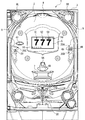
以下、図面を参照しつつ、本発明の一実施形態を詳細に説明する。図1は、本実施の形態におけるパチンコ遊技機の正面図であり、主要部材の配置レイアウトを示す。パチンコ遊技機(遊技機)1は、大別して、遊技盤面を構成する遊技盤(ゲージ盤)2と、遊技盤2を支持固定する遊技機用枠(台枠)3とから構成されている。遊技盤2には、ガイドレールによって囲まれた、ほぼ円形状の遊技領域が形成されている。この遊技領域には、遊技媒体としての遊技球が、所定の打球発射装置から発射されて打ち込まれる。
Hereinafter, an embodiment of the present invention will be described in detail with reference to the drawings. FIG. 1 is a front view of a pachinko gaming machine according to the present embodiment and shows an arrangement layout of main members. The pachinko gaming machine (gaming machine) 1 is roughly composed of a gaming board (gauge board) 2 constituting a gaming board surface and a gaming machine frame (base frame) 3 for supporting and fixing the
遊技盤2の所定位置(図1に示す例では、遊技領域の右側方)には、第1特別図柄表示装置4Aと、第2特別図柄表示装置4Bとが設けられている。第1特別図柄表示装置4Aと第2特別図柄表示装置4Bはそれぞれ、例えば7セグメントやドットマトリクスのLED(発光ダイオード)等から構成され、可変表示ゲームの一例となる特図ゲームにおいて、各々が識別可能な複数種類の識別情報(特別識別情報)である特別図柄(「特図」ともいう)を、変動可能に表示(可変表示)する。例えば、第1特別図柄表示装置4Aと第2特別図柄表示装置4Bはそれぞれ、「0」〜「9」を示す数字や「−」を示す記号等から構成される複数種類の特別図柄を可変表示する。なお、第1特別図柄表示装置4Aや第2特別図柄表示装置4Bにて表示される特別図柄は、「0」〜「9」を示す数字や「−」を示す記号等から構成されるものに限定されず、例えば7セグメントのLEDにおいて点灯させるものと消灯させるものとの組合せを異ならせた複数種類の点灯パターンが、複数種類の特別図柄として予め設定されていればよい。複数種類の特別図柄には、それぞれに対応した図柄番号が付されている。一例として、「0」〜「9」を示す数字それぞれには、「0」〜「9」の図柄番号が付され、「−」を示す記号には、「10」の図柄番号が付されていればよい。以下では、第1特別図柄表示装置4Aにより可変表示される特別図柄を「第1特図」ともいい、第2特別図柄表示装置4Bにより可変表示される特別図柄を「第2特図」ともいう。
A first special
遊技盤2における遊技領域の中央付近には、画像表示装置5が設けられている。画像表示装置5は、例えばLCD(液晶表示装置)等から構成され、各種の演出画像を表示する表示領域を形成している。画像表示装置5の表示領域では、特図ゲームにおける第1特別図柄表示装置4Aによる第1特図の可変表示や第2特別図柄表示装置4Bによる第2特図の可変表示のそれぞれに対応して、例えば3つといった複数に分割された可変表示部となる飾り図柄表示エリアにて、各々が識別可能な複数種類の識別情報(装飾識別情報)である飾り図柄を可変表示する。この飾り図柄の可変表示(変動表示)も、可変表示ゲームに含まれる。
An
一例として、画像表示装置5の表示領域には、「左」、「中」、「右」の飾り図柄表示エリア5L、5C、5Rが配置されている。そして、特図ゲームにおいて第1特別図柄表示装置4Aによる第1特図の変動と第2特別図柄表示装置4Bによる第2特図の変動のいずれかが開始されることに対応して、「左」、「中」、「右」の各飾り図柄表示エリア5L、5C、5Rにて飾り図柄の変動(例えば上下方向のスクロール表示や回転等による更新表示など)が開始される。その後、特図ゲームにおける可変表示結果として確定特別図柄が停止表示されるときに、画像表示装置5における「左」、「中」、「右」の各飾り図柄表示エリア5L、5C、5Rにて、飾り図柄の可変表示結果となる確定飾り図柄(最終停止図柄)が停止表示される。なお、「左」、「中」、「右」の各飾り図柄表示エリアは、画像表示装置5の表示領域内で移動可能とされ、飾り図柄を縮小あるいは拡大して表示することができるようにしてもよい。
As an example, “left”, “middle”, and “right” decorative
このように、画像表示装置5の表示領域では、第1特別図柄表示装置4Aによる第1特図を用いた特図ゲーム、又は、第2特別図柄表示装置4Bによる第2特図を用いた特図ゲームと同期して、各々が識別可能な複数種類の飾り図柄の可変表示を行い、可変表示結果となる確定飾り図柄を導出表示する。なお、例えば特別図柄や飾り図柄といった、各種の表示図柄を導出表示するとは、飾り図柄等の識別情報を停止表示(完全停止表示や最終停止表示ともいう)して可変表示を終了させることである。これに対して、飾り図柄の可変表示を開始してから可変表示結果となる確定飾り図柄が導出表示されるまでの可変表示中には、飾り図柄の変動速度が「0」となって、飾り図柄が停留して表示され、例えば微少な揺れや伸縮などを生じさせる表示状態となることがある。このような表示状態は、仮停止表示ともいい、可変表示における表示結果が確定的に表示されていないものの、スクロール表示や更新表示による飾り図柄の変動が進行していないことを遊技者が認識可能となる。なお、仮停止表示には、微少な揺れや伸縮なども生じさせず、所定時間(例えば1秒間)よりも短い時間だけ、飾り図柄を完全停止表示することなどが含まれてもよい。
As described above, in the display area of the
画像表示装置5では、各飾り図柄表示エリア5L、5C、5Rとなる表示領域として、3つの領域が接着して、あるいは、分離して、あるいは、接着及び分離が可能に、設けられてもよい。画像表示装置5における表示動作は、図3に示す演出制御基板12に搭載されている演出制御用CPU120によって制御される。演出制御用CPU120は、第1特別図柄表示装置4Aで第1特図の可変表示が実行されているときに、その可変表示に伴って画像表示装置5で演出表示を実行させ、第2特別図柄表示装置4Bで第2特図の可変表示が実行されているときに、その可変表示に伴って画像表示装置5で演出表示を実行させるので、遊技の進行状況を把握しやすくすることができる。
「左」、「中」、「右」の各飾り図柄表示エリア5L、5C、5Rにて可変表示される飾り図柄には、例えば8種類の図柄(英数字「1」〜「8」あるいは漢数字「一」〜「八」、英文字「A」〜「H」、所定のモチーフに関連する8個のキャラクタ画像、数字や文字あるいは記号とキャラクタ画像との組合せなど。なお、キャラクタ画像は、例えば人物や動物、これら以外の物体、もしくは、文字などの記号、あるいは、その他の任意の図形を示す飾り画像であればよい。)で構成される。また、こうした8種類の飾り図柄の他に、ブランク図柄(大当り組合せを構成しない図柄)が含まれていてもよい。飾り図柄のそれぞれには、対応する図柄番号が付されている。例えば、「1」〜「8」を示す英数字それぞれに対して、「1」〜「8」の図柄番号が付されている。なお、飾り図柄は8種類に限定されず、大当り組合せやハズレとなる組合せなど適当な数の組合せを構成可能であれば、何種類であってもよい(例えば7種類や9種類など)。
In the
The decorative symbols variably displayed in the “left”, “middle”, and “right” decorative
飾り図柄の変動中には、「左」、「中」、「右」の各飾り図柄表示エリア5L、5C、5Rにおいて、例えば図柄番号が小さいものから大きいものへと順次に上方から下方へと流れるようなスクロール表示が行われ、図柄番号が最大(例えば「8」)である飾り図柄が表示されると、続いて図柄番号が最小(例えば「1」)である飾り図柄が表示される。あるいは、飾り図柄表示エリア5L、5C、5Rのうち少なくともいずれか1つ(例えば「左」の飾り図柄表示エリア5Lなど)において、図柄番号が大きいものから小さいものへとスクロール表示を行って、図柄番号が最小である飾り図柄が表示されると、続いて図柄番号が最大である飾り図柄が表示されるようにしてもよい。
During the change of the decorative symbol, in the decorative
画像表示装置5の表示領域には、表示領域下方隅部には、第1保留記憶数が表示される第1保留記憶数表示エリア5Dが形成(配置)されているとともに、これら第1保留記憶数表示エリア5Dと対角位置となる表示領域上方隅部には、第2保留記憶数が表示される第2保留記憶数表示エリア5Uが形成(配置)されている。第1保留記憶数表示エリア5Dでは、第1特図ゲームに対応した可変表示の保留数(特図保留記憶数)を特定可能に表示し、第2保留記憶数表示エリア5Uでは、第2特図ゲームに対応した可変表示の保留数(特図保留記憶数)を特定可能に表示する保留記憶表示が行われる。ここで、第1特図ゲームや第2特図ゲームに対応した可変表示の保留は、普通入賞球装置6Aが形成する第1始動入賞口や、普通可変入賞球装置6Bが形成する第2始動入賞口を、遊技球が通過(進入)することによる始動入賞に基づいて発生する。すなわち、特図ゲームや飾り図柄の可変表示といった可変表示ゲームを実行するための始動条件(「実行条件」ともいう)は成立したが、先に成立した開始条件に基づく可変表示ゲームが実行中であることやパチンコ遊技機1が大当り遊技状態や小当り遊技状態に制御されていることなどにより、可変表示ゲームを開始するための開始条件は成立していないときに、成立した始動条件に対応する可変表示の保留が行われる。
In the display area of the
一例として、第1保留記憶数表示エリア5D並びに第2保留記憶数表示エリア5Uには、第1始動入賞口と第2始動入賞口のそれぞれに対応して、始動入賞の発生に基づき先に始動条件が成立した可変表示ゲームから順に左から右へと、表示色が変更される複数の表示部位が設けられている。そして、第1保留記憶数表示エリア5Dでは、第1始動入賞口を遊技球が通過(進入)したことに基づき第1特別図柄表示装置4Aにおける第1特図を用いた特図ゲームの始動条件(第1始動条件)が成立したときには、通常非表示(透過色)となっている表示部位のうちの1つ(例えば非表示となっている第1始動入賞口に対応した表示部位のうち左端の表示部位)を青色表示に変化させる。その後、第1特図を用いた特図ゲームの開始条件(第1開始条件)が成立したときには、第1保留記憶数表示エリア5Dのうちの1つ(例えば青色表示となっている表示部位のうち右端の表示部位)を非表示に戻す。
As an example, the first reserved memory
また、第2保留記憶数表示エリア5Uでは、第2始動入賞口を遊技球が通過(進入)したことに基づき第2特別図柄表示装置4Bにおける第2特図を用いた特図ゲームの始動条件(第2始動条件)が成立したときには、通常非表示となっている表示部位のうちの1つ(例えば非表示となっている第2始動入賞口に対応した表示領域のうち左端の表示部位)を赤色表示に変化させる。その後、第2特図を用いた特図ゲームの開始条件(第2開始条件)が成立したときには、第2保留記憶数表示エリア5Uのうちの1つ(例えば赤色表示となっている表示部位のうち右端の表示部位)を非表示に戻す。
Further, in the second reserved memory
なお、これら第1保留記憶数表示エリア5D並びに第2保留記憶数表示エリア5Uでは、特図保留記憶数を示す数字を表示することなどにより、特図保留記憶数を遊技者等が数字にて認識できるようにしてもよい。また、第1保留記憶数表示エリア5Dと第2保留記憶数表示エリア5Uで表示色を異なるようにしているが、どちらの保留表示が、どの特図保留記憶数に対応しているのかを識別し易くなることから好ましいが、本発明はこれに限定されるものではなく、これら第1保留記憶数表示エリア5D並びに第2保留記憶数表示エリア5Uを、同一の表示色としても良い。また、この実施の形態では、第1保留記憶数表示エリア5Dを表示領域の下方に、第2保留記憶数表示エリア5Uを表示領域の上方に設けるとともに、どちらの保留表示が、どの特図保留記憶数に対応しているのかを識別し易くなることから好ましいが、本発明はこれに限定されるものではなく、これら第1保留記憶数表示エリア5D並びに第2保留記憶数表示エリア5Uを、共に、画像表示装置5の表示領域の上方または下方に配置するようにしても良い。
In the first reserved memory
また、これら第1保留記憶数表示エリア5D並びに第2保留記憶数表示エリア5Uとともに、あるいは第1保留記憶数表示エリア5D並びに第2保留記憶数表示エリア5Uに代えて、特図保留記憶数を表示する表示器を設けるようにしてもよい。図1に示す例では、これら第1保留記憶数表示エリア5D並びに第2保留記憶数表示エリア5Uとともに、第1特別図柄表示装置4A及び第2特別図柄表示装置4Bの上部と下部とに、特図保留記憶数を特定可能に表示するための第1保留表示器25Aと第2保留表示器25Bとが設けられている。第1保留表示器25Aは、普通入賞球装置6Aが形成する第1始動入賞口を通過(進入)した有効始動入賞球数としての第1特図保留記憶数を特定可能に表示する。第2保留表示器25Bは、普通可変入賞球装置6Bが形成する第2始動入賞口を通過(進入)した有効始動入賞球数としての第2特図保留記憶数を特定可能に表示する。第1保留表示器25Aと第2保留表示器25Bはそれぞれ、例えば第1特図保留記憶数と第2特図保留記憶数のそれぞれにおける上限値(例えば「4」)に対応した個数(例えば4個)のLEDを含んで構成されている。
In addition to the first reserved memory
こうして、第1始動条件や第2始動条件が成立したものの、先に開始された特図ゲームが実行中であることや、パチンコ遊技機1が大当り遊技状態や小当り遊技状態に制御されていることなどにより、特図ゲームを開始するための開始条件が成立しないときには、特図ゲームに対応した可変表示の保留が発生する。例えば、第1始動条件が成立したときに、当該第1始動条件の成立に基づく第1特図を用いた特図ゲームを開始するための第1開始条件が成立しなければ、第1特図保留記憶数が1加算(インクリメント)され、第1特図を用いた特図ゲームの実行が保留される。また、第2始動条件が成立したときに、当該第2始動条件の成立に基づく第2特図を用いた特図ゲームを開始するための第2開始条件が成立しなければ、第2特図保留記憶数が1加算(インクリメント)され、第2特図を用いた特図ゲームの実行が保留される。これに対して、第1特図を用いた特図ゲームの実行が開始されるときには、第1特図保留記憶数が1減算(デクリメント)され、第2特図を用いた特図ゲームの実行が開始されるときには、第2特図保留記憶数が1減算(デクリメント)される。
Thus, although the first start condition and the second start condition are satisfied, the special game started first is being executed, and the
第1特図保留記憶数と第2特図保留記憶数とを加算した可変表示の保留記憶数は、特に、合計保留記憶数ともいう。単に「特図保留記憶数」というときには、通常、第1特図保留記憶数、第2特図保留記憶数及び合計保留記憶数のいずれも含む概念を指すが、特に、これらの一部(例えば第1特図保留記憶数と第2特図保留記憶数を含む一方で合計保留記憶数は除く概念)を指すこともあるものとする。 The variable display hold memory number obtained by adding the first special figure hold memory number and the second special figure hold memory number is also referred to as a total hold memory number. When simply referring to the “number of special figure hold memory”, it usually refers to a concept including any of the first special figure hold memory number, the second special figure hold memory number, and the total hold memory number. It may refer to a concept that includes the first special figure reserved memory number and the second special figure reserved memory number but excludes the total reserved memory number).
加えて、画像表示装置5の表示領域には、第1特別図柄表示装置4Aや第2特別図柄表示装置4Bにより実行される特図ゲームにて可変表示される特別図柄を、飾り図柄とは別個に特定可能として表示する特別図柄可変表示エリアが設けられていてもよい。一例として、第1特別図柄表示装置4Aや第2特別図柄表示装置4Bによる特図ゲームにて特別図柄の可変表示が開始されたことに対応して、特別図柄可変表示エリアにて特別図柄の可変表示に対応した「◎」や「○」、「×」などを示す演出画像の変動が開始される。その後、特図ゲームにおける特別図柄の可変表示が終了して確定特別図柄が停止表示されることに対応して、特別図柄可変表示エリアにて確定特別図柄に対応して予め定められた「◎」や「○」、「×」などの演出画像を停止表示すればよい。例えば、特図ゲームにおける確定特別図柄が大当り図柄である場合には特別図柄可変表示エリアに「◎」を停止表示し、小当り図柄である場合には「○」を停止表示し、ハズレ図柄である場合には「×」を停止表示すればよい。
In addition, in the display area of the
画像表示装置5の下方には、普通入賞球装置6Aと、普通可変入賞球装置6Bとが設けられている。普通入賞球装置6Aは、例えば所定の玉受部材によって常に一定の開放状態に保たれる第1始動入賞口を形成する。普通可変入賞球装置6Bは、図3に示す普通電動役物用となるソレノイド81によって、垂直位置となる通常開放状態と傾動位置となる拡大開放状態とに変化する一対の可動翼片を有する電動チューリップ型役物(普通電動役物)を備え、第2始動入賞口を形成する。一例として、普通可変入賞球装置6Bでは、普通電動役物用のソレノイド81がオフ状態であるときに可動翼片が垂直位置となることにより、遊技球が第2始動入賞口を通過(進入)しがたい通常開放状態となる。その一方で、普通可変入賞球装置6Bでは、普通電動役物用のソレノイド81がオン状態であるときに可動翼片が傾動位置となる傾動制御により、遊技球が第2始動入賞口を通過(進入)しやすい拡大開放状態となる。なお、普通可変入賞球装置6Bは、通常開放状態であるときでも、第2始動入賞口には遊技球が進入可能であるものの、拡大開放状態であるときよりも遊技球が進入する可能性が低くなるように構成してもよい。あるいは、普通可変入賞球装置6Bは、通常開放状態において、例えば第2始動入賞口を閉鎖することなどにより、第2始動入賞口には遊技球が進入しないように構成してもよい。
Below the
普通入賞球装置6Aに形成された第1始動入賞口を通過(進入)した遊技球は、例えば図3に示す第1始動口スイッチ22Aによって検出される。普通可変入賞球装置6Bに形成された第2始動入賞口を通過(進入)した遊技球は、例えば図3に示す第2始動口スイッチ22Bによって検出される。第1始動口スイッチ22Aによって遊技球が検出されたことに基づき、所定個数(例えば3個)の遊技球が賞球として払い出され、第1特図保留記憶数が所定の上限値(例えば「4」)以下であれば、第1始動条件が成立する。第2始動口スイッチ22Bによって遊技球が検出されたことに基づき、所定個数(例えば3個)の遊技球が賞球として払い出され、第2特図保留記憶数が所定の上限値(例えば「4」)以下であれば、第2始動条件が成立する。なお、第1始動口スイッチ22Aによって遊技球が検出されたことに基づいて払い出される賞球の個数と、第2始動口スイッチ22Bによって遊技球が検出されたことに基づいて払い出される賞球の個数は、互いに同一の個数であってもよいし、異なる個数であってもよい。
A game ball that has passed (entered) a first start winning opening formed in the normal
普通入賞球装置6Aと普通可変入賞球装置6Bの下方には、特別可変入賞球装置7が設けられている。特別可変入賞球装置7は、図3に示す大入賞口扉用となるソレノイド82によって開閉駆動される大入賞口扉を備え、その大入賞口扉によって開放状態と閉鎖状態とに変化する大入賞口を形成する。一例として、特別可変入賞球装置7では、大入賞口扉用のソレノイド82がオフ状態であるときに大入賞口扉が大入賞口を閉鎖状態にする。その一方で、特別可変入賞球装置7では、大入賞口扉用のソレノイド82がオン状態であるときに大入賞口扉が大入賞口を開放状態にする。特別可変入賞球装置7に形成された大入賞口を通過(進入)した遊技球は、例えば図3に示すカウントスイッチ23によって検出される。
A special variable winning
カウントスイッチ23によって遊技球が検出されたことに基づき、所定個数(例えば15個)の遊技球が賞球として払い出される。こうして、特別可変入賞球装置7において開放状態となった大入賞口を遊技球が通過(進入)したときには、例えば第1始動入賞口や第2始動入賞口といった、他の入賞口を遊技球が通過(進入)したときよりも多くの賞球が払い出される。したがって、特別可変入賞球装置7において大入賞口が開放状態となれば、遊技者にとって有利な第1状態となる。その一方で、特別可変入賞球装置7において大入賞口が閉鎖状態となれば、大入賞口に遊技球を通過(進入)させて賞球を得ることができないため、遊技者にとって不利な第2状態となる。
Based on the detection of game balls by the
遊技盤2の所定位置(図1に示す例では、遊技領域の左側方)には、普通図柄表示器20が設けられている。一例として、普通図柄表示器20は、第1特別図柄表示装置4Aや第2特別図柄表示装置4Bと同様に7セグメントやドットマトリクスのLED等から構成され、特別図柄とは異なる複数種類の識別情報である普通図柄(「普図」あるいは「普通図」ともいう)を変動可能に表示(可変表示)する。このような普通図柄の可変表示は、普図ゲーム(「普通図ゲーム」ともいう)と称される。普通図柄表示器20は、例えば「0」〜「9」を示す数字や「−」を示す記号等から構成される複数種類の普通図柄を可変表示する。複数種類の普通図柄には、それぞれに対応した図柄番号が付されている。一例として、「0」〜「9」を示す数字それぞれには、「0」〜「9」の図柄番号が付され、「−」を示す記号には、「10」の図柄番号が付されていればよい。なお、普通図柄表示器20は、「0」〜「9」を示す数字や「−」を示す記号等を普通図柄として可変表示するものに限定されず、例えば「○」と「×」とを示す装飾ランプ(又はLED)を交互に点灯させることや、「左」、「中」、「右」といった複数の装飾ランプ(又はLED)を所定順序で点灯させることにより、普通図柄を可変表示するものであってもよい。普通図柄表示器20の上方には、普図保留表示器25Cが設けられている。普図保留表示器25Cは、例えば4個のLEDを含んで構成され、通過ゲート41を通過した有効通過球数としての普図保留記憶数を表示する。
A
遊技盤2の表面には、上記の構成以外にも、遊技球の流下方向や速度を変化させる風車及び多数の障害釘が設けられている。また、第1始動入賞口、第2始動入賞口及び大入賞口とは異なる入賞口として、例えば所定の玉受部材によって常に一定の開放状態に保たれる一般入賞口が1つ又は複数設けられてもよい。この場合には、一般入賞口のいずれかに進入した遊技球が所定の一般入賞球スイッチによって検出されたことに基づき、所定個数(例えば10個)の遊技球が賞球として払い出されればよい。遊技領域の最下方には、いずれの入賞口にも進入しなかった遊技球が取り込まれるアウト口が設けられている。
In addition to the above-described configuration, the surface of the
遊技機用枠3の左右上部位置には、効果音等を再生出力するためのスピーカ8L、8Rが設けられており、さらに遊技領域周辺部には、遊技効果ランプ9が設けられている。パチンコ遊技機1の遊技領域における各構造物(例えば普通入賞球装置6A、普通可変入賞球装置6B、特別可変入賞球装置7等)の周囲には、装飾用LEDが配置されていてもよい。
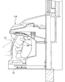
また、画像表示装置5と遊技盤2との間には、後述するシャッタモータ36H、36Lにより駆動されて上下方向に移動することにより、画像表示装置5の前方を開閉可能とされたシャッタ38H,38Lとが設けられている。
Further, between the
遊技機用枠3の右下部位置には、遊技媒体としての遊技球を遊技領域に向けて発射するために遊技者等によって操作される打球操作ハンドル(操作ノブ)が設けられている。例えば、打球操作ハンドルは、遊技者等による操作量(回転量)に応じて遊技球の弾発力を調整する。打球操作ハンドルには、打球発射装置が備える発射モータの駆動を停止させるための単発発射スイッチや、タッチリング(タッチセンサ)が設けられていればよい。遊技領域の下方における遊技機用枠3の所定位置には、賞球として払い出された遊技球や所定の球貸機により貸し出された遊技球を、打球発射装置へと供給可能に保持(貯留)する上皿(打球供給皿)が設けられている。遊技機用枠3の下部には、上皿から溢れた余剰球などを、パチンコ遊技機1の外部へと排出可能に保持(貯留)する下皿が設けられている。
At the lower right position of the
下皿を形成する部材には、例えば下皿本体の上面における手前側の所定位置(例えば下皿の中央部分)などに、遊技者が把持して傾倒操作が可能なスティックコントローラ30が取り付けられている。図2は、スティックコントローラ30の構成例を示している。スティックコントローラ30は、遊技者が把持する操作桿30Aを含み、操作桿30Aの所定位置(例えば遊技者が操作桿30Aを把持したときに操作手の人差し指が掛かる位置など)には、トリガボタン31Aが設けられている。トリガボタン31Aは、遊技者がスティックコントローラ30の操作桿30Aを操作手(例えば左手など)で把持した状態において、所定の操作指(例えば人差し指など)で押引操作することなどにより所定の指示操作ができるように構成されていればよい。操作桿30Aの内部には、トリガボタン31Aに対する押引操作などによる所定の指示操作を検知するトリガセンサ35A(図3を参照)が内蔵されていればよい。スティックコントローラ30の下部における下皿の本体内部などには、操作桿30Aに対する傾倒操作を検知する傾倒方向センサユニット32が設けられていればよい。例えば、傾倒方向センサユニット32は、パチンコ遊技機1と正対する遊技者の側からみて操作桿30Aの中心位置よりも左側で遊技盤2の盤面と平行に配置された2つの透過形フォトセンサ(平行センサ対)と、この遊技者の側からみて操作桿30Aの中心位置よりも右側で遊技盤2の盤面と垂直に配置された2つの透過形フォトセンサ(垂直センサ対)とを組み合わせた4つの透過形フォトセンサを含んで構成されていればよい。なお、下皿におけるスティックコントローラ30の取付位置は、下皿の中央部分に限定されず、左右のいずれかに寄せた位置であってもよい。
A
上皿を形成する部材には、例えば上皿本体の上面における手前側の所定位置(例えばスティックコントローラ30の上方)などに、遊技者が押下操作などにより所定の指示操作を可能なプッシュボタン31Bが設けられている。プッシュボタン31Bは、遊技者からの押下操作などによる所定の指示操作を、機械的、電気的、あるいは、電磁的に、検出できるように構成されていればよい。プッシュボタン31Bの設置位置における上皿の本体内部などには、プッシュボタン31Bに対してなされた遊技者の操作行為を検知するプッシュセンサ35B(図3を参照)が設けられていればよい。図1に示す構成例では、プッシュボタン31Bとスティックコントローラ30の取付位置が、上皿及び下皿の中央部分において上下の位置関係にある。これに対して、上下の位置関係を保ったまま、プッシュボタン31B及びスティックコントローラ30の取付位置を、上皿及び下皿において左右のいずれかに寄せた位置としてもよい。あるいは、プッシュボタン31Bとスティックコントローラ30の取付位置が上下の位置関係にはなく、例えば左右の位置関係にあるものとしてもよい。
The member that forms the upper plate includes, for example, a
スティックコントローラ30に設けられたトリガボタン31Aは、遊技者がスティックコントローラ30の操作桿30Aを操作手で把持した状態において、操作指で押引操作することなどにより指示操作ができるように構成されている。その一方で、プッシュボタン31Bは、スティックコントローラ30とは別個に上皿を形成する遊技機用枠3の所定位置に設けられており、遊技者がスティックコントローラ30の操作桿30Aを把持しない状態などにおいて、操作手で押下操作することなどにより指示操作ができるように構成されている。したがって、トリガボタン31Aは、プッシュボタン31Bに比べて、連続的な指示操作となる連打操作が困難である。
The
普通図柄表示器20による普図ゲームは、遊技領域に設けられた通過ゲート41を通過した遊技球が図3に示すゲートスイッチ21によって検出されたことといった、普通図柄表示器20にて普通図柄の可変表示を実行するための普図始動条件が成立した後に、例えば前回の普図ゲームが終了したことといった、普通図柄の可変表示を開始するための普図開始条件が成立したことに基づいて、開始される。この普図ゲームでは、普通図柄の変動を開始させた後、普図変動時間となる所定時間が経過すると、普通図柄の可変表示結果となる確定普通図柄を停止表示(導出表示)する。このとき、確定普通図柄として、例えば「7」を示す数字といった、特定の普通図柄(普図当り図柄)が停止表示されれば、普通図柄の可変表示結果が「普図当り」となる。その一方、確定普通図柄として、例えば「7」を示す数字以外の数字や記号といった、普図当り図柄以外の普通図柄が停止表示されれば、普通図柄の可変表示結果が「普図ハズレ」となる。普通図柄の可変表示結果が「普図当り」となったことに対応して、普通可変入賞球装置6Bを構成する電動チューリップの可動翼片が傾動位置となる拡大開放制御(傾動制御)が行われ、所定時間が経過すると垂直位置に戻る通常開放制御が行われる。
In the normal game by the
第1特別図柄表示装置4Aによる特図ゲームは、普通入賞球装置6Aに形成された第1始動入賞口を通過(進入)した遊技球が図3に示す第1始動口スイッチ22Aによって検出されたことなどにより第1始動条件が成立した後に、例えば前回の特図ゲームや大当り遊技状態もしくは小当り遊技状態が終了したことなどにより第1開始条件が成立したことに基づいて、開始される。第2特別図柄表示装置4Bによる特図ゲームは、普通可変入賞球装置6Bに形成された第2始動入賞口を通過(進入)した遊技球が図3に示す第2始動口スイッチ22Bによって検出されたことなどにより第2始動条件が成立した後に、例えば前回の特図ゲームや大当り遊技状態もしくは小当り遊技状態が終了したことなどにより第2開始条件が成立したことに基づいて、開始される。
In the special symbol game by the first special
第1特別図柄表示装置4Aや第2特別図柄表示装置4Bによる特図ゲームでは、特別図柄の可変表示を開始させた後、特図変動時間となる所定時間が経過すると、特別図柄の可変表示結果となる確定特別図柄(特図表示結果)を導出表示する。このとき、確定特別図柄として特定の特別図柄(大当り図柄)が停止表示されれば、特定表示結果としての「大当り」となり、大当り図柄とは異なる所定の特別図柄(小当り図柄)が停止表示されれば、所定表示結果としての「小当り」となり、大当り図柄及び小当り図柄とは異なる特別図柄が停止表示されれば「ハズレ」となる。特図ゲームでの可変表示結果が「大当り」になった後には、遊技者にとって有利なラウンド(「ラウンド遊技」ともいう)を所定回数実行する特定遊技状態としての大当り遊技状態に制御される。また、特図ゲームでの可変表示結果が「小当り」になった後には、大当り遊技状態とは異なる小当り遊技状態に制御される。
In the special symbol game by the first special
この実施の形態におけるパチンコ遊技機1では、一例として、「1」、「3」、「7」の数字を示す特別図柄を大当り図柄とし、「2」の数字を示す特別図柄を小当り図柄とし、「−」の記号を示す特別図柄をハズレ図柄としている。なお、第1特別図柄表示装置4Aによる特図ゲームにおける大当り図柄や小当り図柄、ハズレ図柄といった各図柄は、第2特別図柄表示装置4Bによる特図ゲームにおける各図柄とは異なる特別図柄となるようにしてもよいし、双方の特図ゲームにおいて共通の特別図柄が大当り図柄や小当り図柄、ハズレ図柄となるようにしてもよい。
In the
大当り図柄となる「1」、「3」、「7」の数字を示す特別図柄のうち、「3」、「7」の数字を示す特別図柄は15ラウンド大当り図柄となり、「1」の数字を示す特別図柄は2ラウンド大当り図柄となる。特図ゲームにおける確定特別図柄として15ラウンド大当り図柄が停止表示された後に制御される多ラウンド特定遊技状態としての大当り遊技状態(15ラウンド大当り状態)では、特別可変入賞球装置7の大入賞口扉が、第1期間となる所定期間(例えば29秒間)あるいは所定個数(例えば9個)の入賞球が発生するまでの期間にて大入賞口を開放状態とすることにより、特別可変入賞球装置7を遊技者にとって有利な第1状態(開放状態)に変化させるラウンドが実行される。こうしてラウンドの実行中に大入賞口を開放状態とした大入賞口扉は、遊技盤2の表面を落下する遊技球を受け止め、その後に大入賞口を閉鎖状態とすることにより、特別可変入賞球装置7を遊技者にとって不利な第2状態(閉鎖状態)に変化させて、1回のラウンドを終了させる。15ラウンド大当り状態では、大入賞口の開放サイクルであるラウンドの実行回数が、第1ラウンド数(例えば「15」)となる。ラウンドの実行回数が「15」となる15ラウンド大当り状態における遊技は、15回開放遊技とも称される。このような15ラウンド大当り状態では、大入賞口60に遊技球が入賞するたびに15個の出玉(賞球)が得られる。なお、15ラウンド大当り状態は、第1特定遊技状態ともいう。
Of the special symbols that show the numbers "1", "3", and "7" that will be jackpot symbols, the special symbols that show the numbers "3" and "7" will be the 15 round jackpot symbol, and the number "1" The special symbol shown will be a two-round jackpot symbol. In the big hit gaming state (15 round big hit state) as a multi-round specific game state controlled after the 15 round big hit symbol is stopped and displayed as a confirmed special symbol in the special figure game, the special prize winning ball door of the special variable winning
特図ゲームにおける確定特別図柄として2ラウンド大当り図柄が停止表示された後に制御される少ラウンド特定遊技状態としての大当り遊技状態(2ラウンド大当り状態)では、各ラウンドで特別可変入賞球装置7を遊技者にとって有利な第1状態に変化させる期間(大入賞口扉により大入賞口を開放状態とする期間)が、15ラウンド大当り状態における第1期間よりも短い第2期間(例えば0.5秒間)となる。また、2ラウンド大当り状態では、ラウンドの実行回数が、15ラウンド大当り状態における第1ラウンド数よりも少ない第2ラウンド数(例えば「2」)となる。なお、2ラウンド大当り状態では、ラウンドの実行回数が第2ラウンド数となるように制御されればよく、それ以外の制御は15ラウンド大当り状態と同様に行われるようにしてもよい。ラウンドの実行回数が「2」となる2ラウンド大当り状態における遊技は、2回開放遊技とも称される。2ラウンド大当り状態では、各ラウンドで特別可変入賞球装置7とは別個に設けられた所定の入賞球装置において、大入賞口となる所定の入賞口を閉鎖状態から開放状態とすることなどにより、遊技者にとって不利な第2状態から遊技者にとって有利な第1状態に変化させ、所定期間(第1期間又は第2期間)が経過した後に第2状態へと戻すようにしてもよい。
In the big hit gaming state (two round big hit state) as a small round specific gaming state controlled after the 2 round big hit symbol is stopped and displayed as a confirmed special symbol in the special figure game, the special variable winning
このような2ラウンド大当り状態では、大入賞口に遊技球が入賞すれば15個の出玉(賞球)が得られるが、大入賞口の開放期間が第2期間(0.5秒間)であって、非常に短い。そのため、2ラウンド大当り状態は実質的には出玉(賞球)が得られない大当り遊技状態である。なお、2ラウンド大当り状態は、第2特定遊技状態ともいう。また、少ラウンド特定遊技状態としての大当り遊技状態は、多ラウンド特定遊技状態としての大当り遊技状態に比べて、ラウンドの実行回数が少ないものに限定されず、例えばラウンドの実行回数は少ラウンド特定遊技状態と多ラウンド特定遊技状態とで同一である一方で、少ラウンド特定遊技状態では大入賞口を開放状態とする上限期間(例えば2秒間)が多ラウンド特定遊技状態での上限期間(例えば29秒間)に比べて短くなるものであってもよい。すなわち、少ラウンド特定遊技状態としての大当り遊技状態は、各ラウンドで大入賞口を開放状態に変化させる期間が多ラウンド特定遊技状態における第1期間よりも短い第2期間となることと、ラウンドの実行回数が多ラウンド特定遊技状態における第1ラウンド数よりも少ない第2ラウンド数となることのうち、少なくともいずれか一方となるものであればよい。 In such a two-round big hit state, 15 game balls (prize balls) can be obtained if a game ball wins a big winning opening, but the opening period of the big winning opening is the second period (0.5 seconds). It is very short. Therefore, the two-round big hit state is a big hit gaming state in which a ball (prize ball) cannot be obtained substantially. The 2 round big hit state is also referred to as a second specific gaming state. In addition, the big hit gaming state as the low round specific gaming state is not limited to the number of round execution times compared to the big hit gaming state as the multiple round specific gaming state. For example, the round execution number is small round specific gaming state. While the state and the multi-round specific gaming state are the same, in the small-round specific gaming state, the upper limit period (for example, 2 seconds) for opening the big prize opening is the upper limit period for the multi-round specific gaming state (for example, 29 seconds) ) May be shorter. That is, the big hit gaming state as the small round specific gaming state is that the period in which the big prize opening is changed to the open state in each round is a second period shorter than the first period in the multi-round specific gaming state, The number of executions may be at least one of the second round numbers less than the first round number in the multi-round specific gaming state.
また、15ラウンド大当り図柄となる「3」、「7」の数字を示す特別図柄のうち、「3」の数字を示す特別図柄が特図ゲームにおける確定特別図柄として停止表示されたことに基づき15ラウンド大当り状態が終了した後には、特別遊技状態の1つとして、通常状態に比べて特図ゲームにおける特別図柄の可変表示時間(特図変動時間)が短縮される時間短縮制御(時短制御)が行われる時短状態に制御される。ここで、通常状態とは、大当り遊技状態等の特定遊技状態や確変状態及び時短状態とは異なる遊技状態としての通常遊技状態であり、パチンコ遊技機1の初期設定状態(例えばシステムリセットが行われた場合のように、電源投入後に初期化処理を実行した状態)と同一の制御が行われる。時短状態は、所定回数(例えば100回)の特図ゲームが実行されることと、可変表示結果が「大当り」となることのうち、いずれかの条件が先に成立したときに、終了すればよい。こうした「3」の数字を示す特別図柄のように、特図ゲームにおける確定特別図柄として停止表示されたことに基づく大当り遊技状態が終了した後に時短状態に制御される15ラウンド大当り図柄は、非確変大当り図柄(「通常大当り図柄」ともいう)と称される。また、15ラウンド大当り図柄のうち非確変大当り図柄が停止表示されて可変表示結果が「大当り」となることは、「15R非確変大当り」(「15R通常大当り」ともいう)と称される。
Further, among the special symbols indicating the numbers “3” and “7” which are the big hit symbols of 15 rounds, the special symbol indicating the number “3” is stopped and displayed as the confirmed special symbol in the
15ラウンド大当り図柄となる「3」、「7」の数字を示す特別図柄のうち、「7」の数字を示す特別図柄が特図ゲームにおける確定特別図柄として停止表示されたことに基づき15ラウンド大当り状態が終了した後や、2ラウンド大当り図柄となる「1」の数字を示す特別図柄が特図ゲームにおける確定特別図柄として停止表示されたことに基づき2ラウンド大当り状態が終了した後には、時短状態とは異なる特別遊技状態の1つとして、例えば通常状態に比べて特図変動時間が短縮される時短制御とともに、継続して確率変動制御(確変制御)が行われる確変状態(高確率状態)に制御される。この確変状態では、各特図ゲームや飾り図柄の可変表示において、可変表示結果が「大当り」となって更に大当り遊技状態に制御される確率が、通常状態や時短状態よりも高くなるように向上する。このような確変状態は、特図ゲームの実行回数にかかわりなく、次に可変表示結果が「大当り」となるまで継続する。こうした「7」の数字を示す特別図柄のように、特図ゲームにおける確定特別図柄として停止表示されたことに基づく大当り遊技状態が終了した後に確変状態に制御される15ラウンド大当り図柄は、確変大当り図柄と称される。「1」の数字を示す特別図柄のように、特図ゲームにおける確定特別図柄として停止表示されたことに基づく大当り遊技状態が終了した後に確変状態に制御される2ラウンド大当り図柄は、突確大当り図柄と称される。また、15ラウンド大当り図柄のうち確変大当り図柄が停止表示されて可変表示結果が「大当り」となることは、「15R確変大当り」と称される。突確大当り図柄が停止表示されて可変表示結果が「大当り」となることは、「突確大当り」(「2R確変大当り」ともいう)と称される。なお、15ラウンド大当り図柄「3」及び「7」、2ラウンド大当り図柄「1」は一例であり、各大当り図柄はこれらに限定されない。例えば、遊技者に大当り図柄であることや、大当り種別を認識されないようにするために、大当り図柄を数字とせずに予め定められた記号(例えば「コ」など)にしてもよい。 Out of the special symbols that indicate the numbers of “3” and “7” that will be the big hit symbol of 15 rounds, the special symbol that shows the number of “7” is stopped and displayed as a confirmed special symbol in the special figure game. After the status is over, or after the 2 round jackpot state has ended based on the special symbol showing the number “1” that will be the 2 round jackpot symbol being stopped and displayed as a confirmed special symbol in the special game, As one of the special game states different from the normal state, for example, the probability variation state (high probability state) in which the probability variation control (probability variation control) is continuously performed together with the short time control in which the special figure variation time is shortened compared to the normal state. Be controlled. In this probabilistic state, the variable display result of each special figure game and decorative design is improved so that the probability that the variable display result will be “big hit” and further controlled to the big hit gaming state will be higher than in the normal state and the short-time state. To do. Such a probability change state continues until the next variable display result is a “big hit”, regardless of the number of executions of the special game. Like the special symbol indicating the number “7”, the 15 round jackpot symbol that is controlled to be probable after the jackpot gaming state based on being stopped and displayed as a confirmed special symbol in the special symbol game is It is called a symbol. Like the special symbol indicating the number “1”, the two-round big hit symbol controlled to the probable change state after the big hit gaming state based on being stopped and displayed as the confirmed special symbol in the special figure game is a sudden big hit symbol. It is called. Further, the fact that the probability variable big hit symbol of the 15 round big hit symbols is stopped and displayed and the variable display result becomes “big hit” is called “15R probability big hit”. The fact that the sudden hit symbol is stopped and displayed and the variable display result is “big hit” is referred to as “surprise big hit” (also referred to as “2R probability variable big hit”). The 15 round jackpot symbols “3” and “7” and the 2 round jackpot symbol “1” are examples, and each jackpot symbol is not limited to these. For example, in order to prevent the player from recognizing the jackpot symbol or the type of jackpot, the jackpot symbol may not be a number but may be a predetermined symbol (for example, “co”).
小当り図柄となる「2」の数字を示す特別図柄が特図ゲームにおける確定特別図柄として停止表示された後には、小当り遊技状態に制御される。この小当り遊技状態では、2ラウンド大当り状態と同様に特別可変入賞球装置7において大入賞口を遊技者にとって有利な第1状態(開放状態)に変化させる可変入賞動作が行われる。すなわち、小当り遊技状態では、例えば特別可変入賞球装置7を第2期間にわたり第1状態(開放状態)とする動作が、第2回数(第2ラウンド数に等しい実行回数)に達するまで繰り返し実行される。なお、小当り遊技状態では、2ラウンド大当り状態と同様に、特別可変入賞球装置7を第1状態とする期間が第2期間となることと、第1状態とする動作の実行回数が第2回数となることのうち、少なくともいずれか一方が行われるように制御されればよい。小当り遊技状態が終了した後には、遊技状態の変更が行われず、可変表示結果が「小当り」となる以前の遊技状態に継続して制御されることになる。ただし、可変表示結果が「小当り」となる特図ゲームが実行されたときに、特別遊技状態における特図ゲームの実行回数が所定回数に達していれば、小当り遊技状態の終了後には、特別遊技状態が終了して通常状態となることがある。可変入賞動作により特別可変入賞球装置7を第1状態とする回数が「2」である小当り遊技状態における遊技は、2ラウンド大当り状態における遊技と同様に、2回開放遊技とも称される。なお、2ラウンド大当り状態における各ラウンドで特別可変入賞球装置7とは別個に設けられた入賞球装置を第1状態に変化させる場合には、小当り遊技状態でも、2ラウンド大当り状態と同様の態様で、その入賞球装置を第1状態に変化させるようにすればよい。
After the special symbol indicating the number “2” as the small hit symbol is stopped and displayed as the confirmed special symbol in the special symbol game, the small hit game state is controlled. In this small hit game state, similarly to the two round big hit state, the special variable winning
確変状態や時短状態では、普通図柄表示器20による普図ゲームにおける普通図柄の変動時間(普図変動時間)を通常状態のときよりも短くする制御や、各回の普図ゲームで普通図柄の可変表示結果が「普図当り」となる確率を通常状態のときよりも向上させる制御、可変表示結果が「普図当り」となったことに基づく普通可変入賞球装置6Bにおける可動翼片の傾動制御を行う傾動制御時間を通常状態のときよりも長くする制御、その傾動回数を通常状態のときよりも増加させる制御といった、遊技球が第2始動入賞口を通過(進入)しやすくして第2始動条件が成立する可能性を高めることで遊技者にとって有利となる制御が行われる。なお、確変状態や時短状態では、これらの制御のいずれか1つが行われるようにしてもよいし、複数の制御が組み合わせられて行われるようにしてもよい。このように、確変状態や時短状態において第2始動入賞口に遊技球が進入しやすくして遊技者にとって有利となる制御は、高開放制御ともいう。高開放制御が行われることにより、第2始動入賞口は、高開放制御が行われていないときよりも拡大開放状態となる頻度が高められる。これにより、第2特別図柄表示装置4Bにおける第2特図を用いた特図ゲームを実行するための第2始動条件が成立しやすくなり、特図ゲームが頻繁に実行可能となることで、次に可変表示結果が「大当り」となるまでの時間が短縮される。したがって、確変状態や時短状態では、通常状態に比べて大当り遊技状態となりやすくなる。高開放制御が実行可能となる期間は、高開放制御期間ともいい、この期間は、パチンコ遊技機1における遊技状態が確変状態と時短状態のいずれかに制御されている期間と同一であればよい。また、高開放制御期間であるときには、遊技状態が高ベース中であるともいう。これに対して、高開放制御期間でないときには、遊技状態が低ベース中であるともいう。この実施の形態における時短状態は、低確高ベース状態とも称される遊技状態であり、通常状態は、低確低ベース状態とも称される遊技状態であり、後述する高開放制御期間ではない確変状態である潜伏確変状態は高確低ベース状態とも称される遊技状態である。
In the probabilistic state or the short time state, the normal
確変状態のうちには、確変制御とともに時短制御や高開放制御が行われるものの他に、確変制御のみが行われて時短制御や高開放制御が行われないもの(潜伏確変)が含まれていてもよい。一例として、特図ゲームにおける可変表示結果が「15R確変大当り」となったことに基づく15ラウンド大当り状態の終了後には、確変制御とともに時短制御や高開放制御が行われる第1確変状態(高確高ベース状態ともいう)に制御される。その後、特図表示結果が「大当り」となることなく、特図ゲームの実行回数が所定回数(例えば100回)に達したときには、確変制御は継続して行われるものの、時短制御や高開放制御が終了して行われなくなる第2確変状態(高確低ベース状態ともいう)に制御されるようにしてもよい。また、通常状態であるときに特図ゲームにおける可変表示結果が「突確大当り」となったことに基づく2ラウンド大当り状態の終了後には、第2確変状態(潜伏確変状態)へと移行して、確変制御のみが行われ、時短制御や高開放制御は行われないようにしてもよい。その一方で、確変状態や時短状態であるときに特図ゲームにおける可変表示結果が「突確大当り」となったことに基づく2ラウンド大当り状態の終了後には、第1確変状態へと移行して、確変制御とともに時短制御や高開放制御が行われるようにしてもよい。あるいは、「15R確変大当り」に基づく15ラウンド大当り状態の終了後には、再び特図表示結果が「大当り」となるまで第1確変状態に制御される一方、「突確大当り」に基づく2ラウンド大当り状態の終了後には、第1確変状態に移行して、特図表示結果が「大当り」となることなく特図ゲームの実行回数が所定回数に達したときに、第2確変状態へと移行するようにしてもよい。時短制御と高開放制御は、それらの開始と終了が同時に(連動して)行われる一方で、確変制御の開始と終了は、時短制御や高開放制御の開始や終了と必ずしも連動するものでなくてもよい。 Probability change states include not only those with time-varying control and high-opening control, but also those with time-varying control and high-opening control (latent probability changing). Also good. As an example, after the end of the 15 round big hit state based on the fact that the variable display result in the special figure game is “15R probable big hit”, the first probable state (high accuracy (Also called a high base state). After that, when the number of executions of the special figure game reaches a predetermined number (for example, 100 times) without the special figure display result being “big hit”, the probability variation control is continuously performed, but the time reduction control or the high opening control is performed. It is also possible to control to a second certain variation state (also referred to as a high certainty low base state) that is not performed after the completion of. In addition, after the end of the two round big hit state based on the fact that the variable display result in the special game is “surprise big hit” in the normal state, the state shifts to the second probability variation state (latency probability variation state), Only the probability variation control may be performed, and the time reduction control or the high opening control may not be performed. On the other hand, after the end of the two round big hit state based on the fact that the variable display result in the special figure game is “surprise big hit” when in the probability changing state or the short time state, the state shifts to the first probability changing state, Short time control and high opening control may be performed together with the probability variation control. Alternatively, after the 15-round big hit state based on “15R probable big hit”, the control is made to the first positive change state until the special figure display result becomes “big hit” again, while the 2-round big hit state based on “surprise big hit” After the completion of, the transition to the first certain change state is made, and when the number of executions of the special figure game reaches a predetermined number without the special figure display result being “big hit”, the second certain change state is entered. It may be. While the short-time control and the high-open control are started and ended simultaneously (interlocked), the start and end of the probability variation control is not necessarily linked to the start and end of the short-time control and high-open control. May be.
画像表示装置5に設けられた「左」、「中」、「右」の飾り図柄表示エリア5L、5C、5Rでは、第1特別図柄表示装置4Aにおける第1特図を用いた特図ゲームと、第2特別図柄表示装置4Bにおける第2特図を用いた特図ゲームとのうち、いずれかの特図ゲームが開始されることに対応して、飾り図柄の可変表示(変動表示)が開始される。そして、飾り図柄の可変表示が開始されてから「左」、「中」、「右」の各飾り図柄表示エリア5L、5C、5Rにおける確定飾り図柄の停止表示により可変表示が終了するまでの期間では、飾り図柄の可変表示状態が所定のリーチ状態となることがある。ここで、リーチ状態とは、画像表示装置5の表示領域にて仮停止表示された飾り図柄が大当り組合せの一部を構成しているときに未だ仮停止表示もされていない飾り図柄(「リーチ変動図柄」ともいう)については変動が継続している表示状態、あるいは、全部又は一部の飾り図柄が大当り組合せの全部又は一部を構成しながら同期して変動している表示状態のことである。具体的には、「左」、「中」、「右」の飾り図柄表示エリア5L、5C、5Rにおける一部(例えば「左」及び「右」の飾り図柄表示エリア5L、5Rなど)では予め定められた大当り組合せを構成する飾り図柄(例えば「7」の英数字を示す飾り図柄)が仮停止表示されているときに未だ仮停止表示もしていない残りの飾り図柄表示エリア(例えば「中」の飾り図柄表示エリア5Cなど)では飾り図柄が変動している表示状態、あるいは、「左」、「中」、「右」の飾り図柄表示エリア5L、5C、5Rにおける全部又は一部で飾り図柄が大当り組合せの全部又は一部を構成しながら同期して変動している表示状態である。
In the “left”, “middle”, and “right” decorative
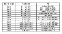
また、リーチ状態となったことに対応して、飾り図柄の変動速度を低下させたり、画像表示装置5の表示領域に飾り図柄とは異なるキャラクタ画像(人物等を模した演出画像)を表示させたり、背景画像の表示態様を変化させたり、飾り図柄とは異なる動画像を再生表示させたり、飾り図柄の変動態様を変化させたりすることで、リーチ状態となる以前とは異なる演出動作が実行される場合がある。このようなキャラクタ画像の表示や背景画像の表示態様の変化、動画像の再生表示、飾り図柄の変動態様の変化といった演出動作を、リーチ演出表示(あるいは単にリーチ演出)という。なお、リーチ演出には、画像表示装置5における表示動作のみならず、スピーカ8L、8Rによる音声出力動作や、遊技効果ランプ9などの発光体における点灯動作(点滅動作)や、シャッタ38H,38L等の可動物などを、リーチ状態となる以前の動作態様とは異なる動作態様とすることが、含まれていてもよい。リーチ演出における演出動作としては、互いに動作態様(リーチ態様)が異なる複数種類の演出パターン(「リーチパターン」ともいう)が、予め用意されていればよい。そして、それぞれのリーチ態様では「大当り」となる可能性(「信頼度」あるいは「大当り信頼度」ともいう)が異なる。すなわち、複数種類のリーチ演出のいずれが実行されるかに応じて、可変表示結果が「大当り」となる可能性を異ならせることができる。一例として、この実施の形態では、ノーマルリーチ、スーパーリーチα、スーパーリーチβといったリーチ態様が予め設定されている。そして、スーパーリーチαやスーパーリーチβといったスーパーリーチのリーチ態様が出現した場合には、ノーマルリーチのリーチ態様が出現した場合に比べて、可変表示結果が「大当り」となる可能性(大当り期待度)が高くなる。
Further, in response to the reach state, the variation speed of the decorative design is reduced, or a character image (an effect image simulating a person) different from the decorative design is displayed in the display area of the
飾り図柄の可変表示中には、リーチ演出とは異なり、飾り図柄の可変表示状態がリーチ状態となる可能性があることや、可変表示結果が「大当り」となる可能性があることを、飾り図柄の可変表示態様などにより遊技者に報知するための可変表示演出が実行されることがある。この実施の形態では、「滑り」や「擬似連」といった可変表示演出が実行可能であり、主基板11の側で変動パターンが決定されることなどに対応して、各々の演出動作を実行するか否かが決定される。
During the variable display of decorative designs, unlike the reach production, the decorative display variable display state may become the reach state and the variable display result may be a “hit”. There may be a case where a variable display effect for notifying the player is given by a variable display mode of the symbol or the like. In this embodiment, variable display effects such as “sliding” and “pseudo-continuous” can be executed, and each effect operation is executed in response to a change pattern being determined on the
「滑り」の可変表示演出では、「左」、「中」、「右」の飾り図柄表示エリア5L、5C、5Rにおける全部にて飾り図柄を変動させてから、2つ以上の飾り図柄表示エリア(例えば「左」及び「右」の飾り図柄表示エリア5L、5Rなど)にて飾り図柄を仮停止表示させた後、その仮停止表示した飾り図柄表示エリアのうち所定数(例えば「1」又は「2」)の飾り図柄表示エリア(例えば「左」の飾り図柄表示エリア5Lと「右」の飾り図柄表示エリア5Rのいずれか一方又は双方)にて飾り図柄を再び変動させた後に停止表示させることで、停止表示する飾り図柄を変更させる演出表示が行われる。
In the variable display effect of “sliding”, two or more decorative symbol display areas are displayed after changing the decorative symbols in all of the “left”, “middle”, and “right” decorative
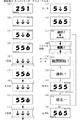
「擬似連」の可変表示演出では、特図ゲームの第1開始条件と第2開始条件のいずれか一方が1回成立したことに対応して、飾り図柄の可変表示が開始されてから可変表示結果となる確定飾り図柄が導出表示されるまでに、「左」、「中」、「右」の飾り図柄表示エリア5L、5C、5Rにおける全部にて飾り図柄を一旦仮停止表示させた後、全部の飾り図柄表示エリア5L、5C、5Rにて飾り図柄を再び変動(擬似連変動)させる演出表示を、所定回(例えば最大3回まで)行うことができる。擬似連変動の回数は、飾り図柄の可変表示が開始されてから全部の飾り図柄が最初に一旦仮停止するまでの初回変動を除く、「左」、「中」、「右」の飾り図柄表示エリア5L、5C、5Rにおける全部にて飾り図柄が再変動する回数である。一例として、「擬似連」の可変表示演出では、「左」、「中」、「右」の飾り図柄表示エリア5L、5C、5Rにて、図4(A)に示すような特殊組合せの擬似連チャンス目GC1〜GC8として予め定められた複数種類のハズレ組合せのいずれかとなる飾り図柄が仮停止表示される。ここで、図4(A)などに示す「左図柄」は「左」の飾り図柄表示エリア5Lに仮停止表示される飾り図柄であり、「中図柄」は「中」の飾り図柄表示エリア5Cに表示される飾り図柄であり、「右図柄」は「右」の飾り図柄表示エリア5Rに表示される飾り図柄である。なお、仮停止表示では、飾り図柄が停留して表示される一方で、例えば揺れ変動表示を行うことや短時間の停留だけで直ちに飾り図柄を再変動させることなどによって、遊技者に表示されている飾り図柄が確定しない旨を報知すればよい。あるいは、仮停止表示でも、一旦表示された飾り図柄が確定したと遊技者が認識する程度に飾り図柄を停留させてから、飾り図柄を再変動させるようにしてもよい。
In the “pseudo-ream” variable display effect, the variable display of the decorative symbol is started in response to one of the first start condition and the second start condition of the special figure game being satisfied once. Before the final determined decorative symbol is derived and displayed, the decorative symbols are temporarily stopped and displayed in all of the “left”, “middle”, and “right” decorative
「擬似連」の可変表示演出では、擬似連変動(再変動)の回数が多くなるに従って、可変表示結果が「大当り」となる可能性が高くなるように設定されていればよい。これにより、遊技者は、擬似連チャンス目GC1〜GC8のいずれかが仮停止表示されることにより、「擬似連」の可変表示演出が行われることを認識でき、擬似連変動の回数が多くなるに従って、可変表示結果が「大当り」となる期待感が高められる。この実施の形態では、「擬似連」の可変表示演出において、擬似連変動(再変動)が1回〜3回行われることにより、第1開始条件あるいは第2開始条件が1回成立したことに基づき、飾り図柄の可変表示があたかも2回〜4回続けて開始されたかのように見せることができる。なお、「擬似連」の可変表示演出における擬似連変動(再変動)の回数は、例えば4回や5回といった、1回〜3回よりも多くの回数まで実行できるようにしてもよい。 In the “pseudo-continuous” variable display effect, the variable display result may be set so that the possibility that the variable display result becomes “big hit” increases as the number of pseudo-continuous changes (re-changes) increases. Accordingly, the player can recognize that the variable display effect of “pseudo-continuous” is performed by temporarily stopping display of any one of the pseudo-continuous chances GC1 to GC8, and the number of pseudo-continuous fluctuations increases. Accordingly, the expectation that the variable display result becomes “big hit” is enhanced. In this embodiment, in the variable display effect of “pseudo-continuous”, the first start condition or the second start condition is satisfied once by performing the pseudo-continuous change (re-change) once to three times. Based on this, it is possible to make it appear as if the variable display of the decorative symbols has been started 2 to 4 times in succession. Note that the number of pseudo-continuous fluctuations (re-variations) in the “pseudo-continuous” variable display effect may be executed more than one to three times, for example, four or five times.
「擬似連」の可変表示演出が実行される際には、初回変動を含む複数回の変動表示(擬似連変動)に伴って、関連する表示演出やシャッタ38H,38L等の可動物の動作などによる再変動演出が実行されるようにしてもよい。一例として、「擬似連」の可変表示演出による各変動表示(初回変動を含む)の期間中に、遊技領域の内部又は外部に設けられた複数の装飾用LEDのうちで点灯されるものが1つずつ増えていくように制御されてもよい。また、各変動表示(初回変動を含む)の期間中に、装飾用LEDの表示色が変化するように制御されてもよいし、複数の装飾用LEDのうちで点灯されるものが変化するように制御されてもよい。他の一例として、「擬似連」の可変表示演出による各変動表示(初回変動を含む)の期間中に、シャッタ38H,38L等の可動物や、遊技領域の内部又は外部に設けられた演出用模型(可動部材)が動作するように制御されてもよい。さらに他の一例として、「擬似連」の可変表示演出による各変動表示(初回変動を含む)の期間中に、画像表示装置5において特定のキャラクタ画像といった所定の演出画像を表示するように制御されてもよい。これらの再変動演出の一部又は全部に加えて、あるいは、これらの再変動演出の一部又は全部に代えて、装飾用LEDの点灯や点滅、演出用模型の動作、演出画像の表示のうち、一部又は全部を組み合わせた再変動演出を実行するように制御されてもよい。このとき、1種類の演出態様のみで再変動演出が実行される場合よりも、複数種類の演出態様を組み合わせた再変動演出が実行される期間を含んでいる場合や、複数回の再変動演出における演出態様が変化する場合に、可変表示結果が「大当り」となる可能性や、「15R確変大当り」となる可能性などが高まるようにしてもよい。
When the “pseudo-continuous” variable display effect is executed, a related display effect, movement of movable objects such as the
再変動演出として実行される演出動作は、例えばスピーカ8L、8Rからの音声出力や、遊技効果ランプ9といった他の発光体の点灯動作といった、任意の演出動作を含んだものであってもよい。また、例えばスピーカ8L、8Rによる音声や効果音の出力の違い、演出対象物(例えば演出用模型など)の動きの違い(動作速度の違い、動作する距離の違い、動作方向の違いなど)、画像表示装置5に表示されるキャラクタ画像の動きの違い(動作速度の違い、動作する距離の違い、動作方向の違いなど)によって再変動演出の演出態様を相違させたり、画像表示装置5においてキャラクタ画像ではなく文字表示を変化させたり背景画像の表示を変化させたりして、再変動演出における演出態様を相違させてもよい。さらに、飾り図柄の変動中に実行される再変動演出とは別に、擬似連チャンス目GC1〜GC8のいずれかとなる飾り図柄の仮停止時などに、例えばスピーカ8L、8Rからの音声出力や、遊技効果ランプ9などの発光体の点灯動作といった、任意の演出動作によりチャンス目が仮停止表示されたことを遊技者が認識できるようにしてもよい。
The production operation executed as the re-variation production may include any production operation such as sound output from the
こうした飾り図柄の可変表示動作を利用した可変表示演出としては、「滑り」や「擬似連」の他にも、例えば「発展チャンス目」や「発展チャンス目終了」、「チャンス目停止後滑り」といった、各種の演出動作が実行されてもよい。ここで、「発展チャンス目」の可変表示演出では、飾り図柄の可変表示が開始されてから可変表示結果となる確定飾り図柄が導出表示されるまでに、「左」、「中」、「右」の飾り図柄表示エリア5L、5C、5Rにおける全部にて、予め定められた特殊組合せに含まれる発展チャンス目を構成する飾り図柄を仮停止表示させた後、飾り図柄の可変表示状態をリーチ状態として所定のリーチ演出が開始される。これにより、発展チャンス目を構成する飾り図柄が仮停止表示されたときには、飾り図柄の可変表示状態がリーチ状態となることや、リーチ状態となった後に可変表示結果が「大当り」となることに対する期待感が高められる。また、「発展チャンス目終了」の可変表示演出では、飾り図柄の可変表示が開始された後に、「左」、「中」、「右」の飾り図柄表示エリア5L、5C、5Rにおける全部にて、発展チャンス目として予め定められた組合せの飾り図柄を、確定飾り図柄として導出表示させる演出表示が行われる。「チャンス目停止後滑り」の可変表示演出では、「擬似連」の可変表示演出と同様に、飾り図柄の可変表示が開始されてから可変表示結果となる確定飾り図柄が導出表示されるまでに、「左」、「中」、「右」の飾り図柄表示エリア5L、5C、5Rにおける全部にて擬似連チャンス目GC1〜GC8のいずれかとなるハズレ組合せ(特殊組合せ)の飾り図柄を一旦仮停止表示させた後、「擬似連」の可変表示演出とは異なり、飾り図柄表示エリア5L、5C、5Rの一部にて飾り図柄を再び変動させることで、停止表示する飾り図柄を変更させる演出表示が行われる。
In addition to “slip” and “pseudo ream”, variable display effects using the variable display operation of such decorative patterns include, for example, “Development chance eyes”, “Development chance eyes end”, “Slip after chance eyes stop” Various production operations such as these may be executed. Here, in the variable display effect of “Development Opportunity”, “Left”, “Middle”, “Right” from the start of the variable display of the decorative pattern to the display of the fixed decorative pattern resulting in the variable display result. In all of the decorative
飾り図柄の可変表示中には、リーチ演出あるいは「滑り」や「擬似連」などの可変表示演出とは異なり、例えば所定の演出画像を表示することや、メッセージとなる画像表示や音声出力などのように、飾り図柄の可変表示動作とは異なる演出動作により、飾り図柄の可変表示状態がリーチ状態となる可能性があることや、可変表示結果が「大当り」となる可能性があることを、遊技者に報知するための予告演出が実行されることがある。予告演出となる演出動作は、「左」、「中」、「右」の飾り図柄表示エリア5L、5C、5Rの全部にて飾り図柄の可変表示が開始されてから、飾り図柄の可変表示状態がリーチ状態となるより前(「左」及び「右」の飾り図柄表示エリア5L、5Rにて飾り図柄が仮停止表示されるより前)に実行(開始)されるものであればよい。また、可変表示結果が「大当り」となる可能性があることを報知する予告演出には、飾り図柄の可変表示状態がリーチ状態となった後に実行されるものが含まれていてもよい。この実施の形態では、「キャラクタ表示」や「ステップアップ表示」といった表示系予告、及び、「プッシュボタン単発」や「プッシュボタン連打」、「トリガボタン単発」、「トリガボタン連打」といった操作系予告など、複数種類の予告演出が実行可能に設定されている。予告演出となる演出動作は、それが実行されるか否かによっては特別図柄の可変表示時間(特図変動時間)に変化が生じないものであればよい。
During variable display of decorative designs, unlike reach display or variable display effects such as “slip” and “pseudo-run”, for example, displaying a predetermined effect image, displaying a message as an image, outputting sound, etc. As described above, there is a possibility that the variable display state of the decorative design may reach a reach state due to a presentation operation different from the variable display operation of the decorative design, and that the variable display result may be a “hit”. A notice effect may be executed to notify the player. The effect operation that becomes the notice effect is the variable display state of the decorative symbol after the decorative symbol variable display is started in all of the “left”, “middle”, and “right” decorative
「キャラクタ表示」の予告演出では、飾り図柄の可変表示中に、例えば画像表示装置5の表示領域にて、予め用意された複数種類のキャラクタ画像のいずれかを表示させる演出表示が行われる。「ステップアップ表示」の予告演出では、飾り図柄の可変表示中に、例えば画像表示装置5の表示領域にて、予め用意された複数種類の演出画像を所定の順番に従って切り換えて表示させる演出表示により、演出態様が複数段階に変化(ステップアップ)するような演出動作が行われることがある。なお、「ステップアップ表示」の予告演出では、予め用意された複数種類の演出画像のうちいずれか1つ(例えば所定の順番において最初に表示される演出画像など)が表示された後、演出画像が切り換えられることなく、予告演出における演出表示を終了させることがあるようにしてもよい。また、演出画像を切り換えて表示させる演出表示に代えて、あるいは、このような演出表示とともに、例えば演出用の可動部材を所定の順番に従って複数種類の動作態様で動作させる演出動作により、演出態様が複数段階に変化(ステップアップ)するような演出動作が行われるようにしてもよい。
In the “character display” notice effect, during the variable display of the decorative pattern, for example, an effect display in which one of a plurality of types of character images prepared in advance is displayed in the display area of the
こうしたステップアップが可能な予告演出は、1回の始動入賞(第1始動入賞口又は第2始動入賞口に1個の遊技球が進入したこと)に対応して実行される特別図柄や飾り図柄の可変表示中に実行される予告演出の一種であり、特に予告の態様(表示、音、ランプ、シャッタ38H,38L等の可動物や可動部材等による演出内容)が複数段階に変化(ステップアップ)するステップアップ予告演出とも称される。一般的には変化する段階数(ステップ数)が多い程信頼度(可変表示結果が「大当り」となる可能性)が高くなる。また、ステップアップ予告演出におけるステップ数、あるいは、各ステップにおける演出態様に応じて、「15R確変大当り」や「2R確変大当り」となること、特定のリーチ演出が実行されること、「15R非確変大当り」から「15R確変大当り」へと昇格することのうち、少なくともいずれか1つを予告するものであってもよい。さらに変化する回数(ステップ数)によって予告する対象も変化するものでもよい。例えば第2ステップまで行くと「リーチ確定」、第3ステップまで行くと「スーパーリーチ確定」、第4ステップまで行くと「大当り確定」となるようなものでもよい。予告の態様の変化(ステップアップ)としては、異なるキャラクタ画像が順番に表示されるものであってもよいし、1つのキャラクタにおける形状や色等が変化することでステップアップするようなものであってもよい。すなわち、遊技者からみて予告する手段(表示、音、ランプ、可動物等)の状態が段階的に変化したと認識可能なものであればよい。
The notice effect that can be stepped up is a special symbol or decorative symbol that is executed in response to one start prize (that one game ball has entered the first start prize slot or the second start prize slot). Is a kind of notice effect that is executed during variable display, and in particular, the aspect of the notice (display contents, effects by moving objects such as lamps,
「プッシュボタン単発」や「プッシュボタン連打」、「トリガボタン単発」、「トリガボタン連打」といった操作系予告となる予告演出では、飾り図柄の可変表示中に、ボタン操作促進演出となる所定の演出動作が行われるようにすればよい。ボタン操作促進演出は、例えば画像表示装置5の表示領域における所定位置に、予め用意されたキャラクタ画像やメッセージ画像といった演出画像を表示させることなどにより、遊技者によるプッシュボタン31Bやトリガボタン31Aの操作を促す演出動作であればよい。遊技者による操作を促す演出動作としては、画像表示装置5に演出画像を表示させるものに限定されず、スピーカ8L、8Rから所定の音声を出力させるもの、遊技効果ランプ9や装飾用LEDを所定の点灯パターンで点灯あるいは点滅させるもの、遊技領域の内部又は外部に設けられた演出用模型を所定の動作態様で動作させるもの、あるいは、これらのいずれかを組み合わせたものであってもよい。こうしたボタン操作促進演出が行われるときには、遊技者による操作行為を有効に検出する操作有効期間となる。そして、操作有効期間内に遊技者による操作行為が検出されたことに応じて、例えば予め用意された複数種類の演出画像のうちいずれかの演出画像を画像表示装置5に表示させることや、予め用意された複数種類の音声パターンのうちいずれかの音声パターンに対応する効果音をスピーカ8L、8Rから出力させることといった、各種の演出動作が実行される。
In the pre-announcement effect that becomes the operation system advance notice such as “single push button”, “single push button”, “single trigger button”, and “trigger trigger button”, a predetermined effect that is a button operation promotion effect during variable display of decorative symbols The operation may be performed. In the button operation promotion effect, for example, an effect image such as a character image or a message image prepared in advance is displayed at a predetermined position in the display area of the
「プッシュボタン単発」や「トリガボタン単発」の予告演出では、操作有効期間内に遊技者による所定の指示操作(例えばプッシュボタン31Bの押下操作やトリガボタン31Aの押引操作など)が1回検出されたことに基づいて、予告演出における演出態様(演出内容)が変化する。例えば、操作検出がされたことによりシャッタ38H,38Lが動作する演出となる一方、操作検出がされないことにより、画像表示装置5に画像のシャッタが表示される。その後、さらに遊技者による指示操作が検出されても、その検出結果に対応した演出態様の変化は生じないように制御されればよい。あるいは、遊技者による指示操作が1回検出されたときに、操作有効期間を終了させて、以後は遊技者による指示操作が検出されないようにしてもよい。
In the notice effect of “single push button” or “single trigger button”, a predetermined instruction operation by the player (for example, pressing operation of the
「プッシュボタン連打」や「トリガボタン連打」の予告演出では、操作有効期間内に遊技者による所定の指示操作(例えばプッシュボタン31Bの押下操作やトリガボタン31Aの押引操作など)が検出された回数などに基づいて、予告演出における演出態様(演出内容)が変化する。例えば、操作検出が所定回数以上されたことによりシャッタ38H,38Lが動作する演出となる一方、操作検出が所定回数以上されないことにより、画像表示装置5に画像のシャッタが表示される。また、遊技者による指示操作が検出されるごとに、予告演出における演出態様を少しずつ変化させることで、指示操作が検出された回数に応じて演出態様が変化する程度を異ならせるようにしても良い。あるいは、所定時間内に検出された指示操作の合計回数に応じて、演出態様が変化する程度を異ならせるようにしてもよい。
In the notice effect of “push button repeated hits” or “trigger button repeat hits”, a predetermined instruction operation (for example, pressing operation of the
また、「トリガボタン単発」や「トリガボタン連打」の予告演出では、スティックコントローラ30の操作桿30Aに対する傾倒操作に応じて、予告演出における演出態様(演出内容)が変化する。例えば、遊技者による傾倒操作が検出されたときには、検出された傾倒方向に対応する演出画像の切換表示、具体的には、傾倒操作に応じて表示されるキャラクタが移動したりキャラクタが変化したりする等の切換演出を行うことにより、演出画像の表示による演出態様が変化する。したがって、「トリガボタン単発」や「トリガボタン連打」の予告演出では、スティックコントローラ30の操作桿30Aに対する傾倒操作と、トリガボタン31Aに対する指示操作とに応じて、予告演出における演出態様が変化する。これに対して、「プッシュボタン単発」や「プッシュボタン連打」の予告演出では、プッシュボタン31Bに対する指示操作に応じて、予告演出における演出態様が変化する。
In the notice effect of “single trigger button” or “trigger trigger button”, the effect mode (effect contents) of the notice effect changes according to the tilting operation of the
なお、スティックコントローラ30の操作桿30Aに対する傾倒操作とトリガボタン31Aに対する指示操作とに応じて演出態様が変化する演出動作や、プッシュボタン31Bに対する指示操作に応じて演出態様が変化する演出動作は、予告演出に限定されず、例えば変動パターンに対応して実行されるリーチ演出や再変動演出などとして、実行されるようにしてもよい。
An effect operation in which the effect mode changes according to the tilting operation with respect to the operating
これらの予告演出とは個別に、第1保留記憶数表示エリア5D並びに第2保留記憶数表示エリア5Uにおいて、大当りやスーパーリーチとなる可能性を報知するようにしても良い。この実施の形態では、後述するように、有効始動入賞が発生した段階において、該有効始動入賞に対応した乱数を抽出して大当りか否かやスーパーリーチとなるか否か等の抽選を実施し、これら抽選結果に基づいて、該有効始動入賞に該当する保留記憶表示の表示形態を、例えば、通常の丸表示とは異なる星型や菱形に変更することで、大当りやスーパーリーチとなる可能性を報知すれば良い。尚、これらの報知の態様としては、異なる図形を表示するものに限らず、通常とは異なる色や大きさにより報知したり、報知する対象の違い(例えば大当りか、スーパーリーチか等)により、表示形態を個々に異なるようにしても良い。
You may make it alert | report the possibility of becoming a big hit or a super reach in the 1st reserved memory
特図ゲームにおける確定特別図柄として、ハズレ図柄となる特別図柄が停止表示される場合には、飾り図柄の可変表示が開始されてから、飾り図柄の可変表示状態がリーチ状態とならずに、所定の非リーチ組合せとなる確定飾り図柄が停止表示されることがある。このような飾り図柄の可変表示態様は、可変表示結果が「ハズレ」となる場合における「非リーチ」(「リーチ無しハズレ」ともいう)の可変表示態様と称される。 If a special symbol that will be a lost symbol is stopped and displayed as a special symbol to be confirmed in the special symbol game, the decorative symbol variable display state will not reach the reach state after the variable symbol variable display starts. There are cases in which a fixed decorative symbol that is a non-reach combination is stopped and displayed. Such a decorative display variable display mode is referred to as “non-reach” (also referred to as “unreach loss”) variable display mode when the variable display result is “losing”.
特図ゲームにおける確定特別図柄として、ハズレ図柄となる特別図柄が停止表示される場合には、飾り図柄の可変表示が開始されてから、飾り図柄の可変表示状態がリーチ状態となったことに対応して、リーチ演出が実行された後に、所定のリーチ組合せ(リーチハズレ組合せともいう)となる確定飾り図柄が停止表示されることがある。このような飾り図柄の可変表示結果は、可変表示結果が「ハズレ」となる場合における「リーチ」(「リーチハズレ」ともいう)の可変表示態様と称される。なお、非リーチ組合せとなる確定飾り図柄と、リーチ組合せとなる確定飾り図柄は、まとめてハズレ組合せ(非特定の組合せ)の確定飾り図柄ともいう。 When a special symbol that becomes a losing symbol is stopped and displayed as a confirmed special symbol in the special symbol game, it corresponds to the fact that the decorative symbol variable display state has reached the reach state after the decorative symbol variable display has started. Then, after the reach effect is executed, a fixed decorative pattern that becomes a predetermined reach combination (also referred to as reach lose combination) may be stopped and displayed. Such a variable display result of the decorative design is referred to as a variable display mode of “reach” (also referred to as “reach lose”) when the variable display result is “losing”. It should be noted that the fixed decorative pattern that is a non-reach combination and the fixed decorative pattern that is a reach combination are collectively referred to as a fixed decorative pattern of a lost combination (non-specific combination).
特図ゲームにおける確定特別図柄として、15ラウンド大当り図柄となる特別図柄のうち非確変大当り図柄である「3」の数字を示す特別図柄が停止表示される場合には、飾り図柄の可変表示状態がリーチ状態となったことに対応して、所定のリーチ演出が実行された後などに、所定の非確変大当り組合せ(「通常大当り組合せ」ともいう)となる確定飾り図柄が停止表示される。ここで、非確変大当り組合せとなる確定飾り図柄は、例えば画像表示装置5における「左」、「中」、「右」の飾り図柄表示エリア5L、5C、5Rにて可変表示される図柄番号が「1」〜「8」の飾り図柄のうち、図柄番号が偶数「2」、「4」、「6」、「8」である飾り図柄のいずれか1つが、「左」、「中」、「右」の飾り図柄表示エリア5L、5C、5Rにて所定の有効ライン上に揃って停止表示されるものであればよい。このように非確変大当り組合せを構成する図柄番号が偶数「2」、「4」、「6」、「8」である飾り図柄は、非確変図柄(「通常図柄」ともいう)と称される。そして、特図ゲームにおける確定特別図柄が非確変大当り図柄となることに対応して、所定のリーチ演出が実行された後などに、非確変大当り組合せの確定飾り図柄が停止表示される飾り図柄の可変表示態様は、可変表示結果が「大当り」となる場合における「非確変」(「通常大当り」ともいう)の可変表示態様(大当り種別ともいう)と称される。こうして「非確変」の可変表示態様により可変表示結果が「大当り」となった後には、15ラウンド大当り遊技状態に制御され、その15ラウンド大当り状態が終了すると、時短状態に制御される。
When the special symbol indicating the number “3”, which is a non-probable variable jackpot symbol, is stopped and displayed as a special symbol to be confirmed in the special symbol game as a 15-round jackpot symbol, the variable display state of the decorative symbol is changed. Corresponding to the reach state, after a predetermined reach effect is executed, a definite decorative symbol that becomes a predetermined non-probable variation big hit combination (also referred to as “normal big hit combination”) is stopped and displayed. Here, the confirmed decorative symbols that are non-probable big hit combinations are, for example, symbol numbers that are variably displayed in the “left”, “middle”, and “right” decorative
特図ゲームにおける確定特別図柄として、15ラウンド大当り図柄となる特別図柄のうち確変大当り図柄である「7」の数字を示す特別図柄が停止表示される場合には、飾り図柄の可変表示状態がリーチ状態となったことに対応して、大当り種別が「非確変」である場合と同様のリーチ演出が実行された後などに、もしくは、大当り種別が「非確変」である場合とは異なるリーチ演出が実行された後などに、所定の確変大当り組合せとなる確定飾り図柄が停止表示されることがある。ここで、確変大当り組合せとなる確定飾り図柄は、例えば画像表示装置5における「左」、「中」、「右」の飾り図柄表示エリア5L、5C、5Rにて可変表示される図柄番号が「1」〜「8」の飾り図柄のうち、図柄番号が奇数「1」、「3」、「5」、「7」である飾り図柄のいずれか1つが、「左」、「中」、「右」の飾り図柄表示エリア5L、5C、5Rにて所定の有効ライン上に揃って停止表示されるものであればよい。このように確変大当り組合せを構成する図柄番号が奇数「1」、「3」、「5」、「7」である飾り図柄は、確変図柄と称される。そして、特図ゲームにおける確定特別図柄が確変大当り図柄となることに対応して、リーチ演出が実行された後などに、確変大当り組合せの確定飾り図柄が停止表示される飾り図柄の可変表示態様は、可変表示結果が「大当り」となる場合における「確変」の可変表示態様(大当り種別ともいう)と称される。
When the special symbol indicating the number “7”, which is the probability variable big hit symbol, is stopped and displayed as a special symbol to be confirmed in the special figure game as a 15-round big hit symbol, the variable display state of the decorative symbol is reached. Corresponding to the situation, after reaching the same reach effect as when the jackpot type is "non-probable change", or the reach effect different from when the jackpot type is "non-probable change" For example, after the process is executed, a fixed decorative symbol that becomes a predetermined probability variation jackpot combination may be stopped and displayed. Here, the confirmed decorative symbol that is a probable big hit combination has, for example, a symbol number variably displayed in the “left”, “middle”, and “right” decorative
特図ゲームにおける確定特別図柄として確変大当り図柄が停止表示される場合に、飾り図柄の可変表示結果として、非確変大当り組合せとなる確定飾り図柄が停止表示されることがあるようにしてもよい。このように、非確変大当り組合せとなる確定飾り図柄が停止表示される場合でも、特図ゲームにおける確定特別図柄として確変大当り図柄が停止表示されるときは、「確変」の可変表示態様に含まれる。こうして「確変」の可変表示態様により可変表示結果が「大当り」となった後には、15ラウンド大当り状態に制御され、その15ラウンド大当り状態が終了すると、確変状態に制御されることになる。非確変大当り組合せとなる確定飾り図柄や確変大当り組合せとなる確定飾り図柄は、まとめて大当り組合せ(特定の組合せ)の確定飾り図柄ともいう。 When the probability variable big hit symbol is stopped and displayed as a fixed special symbol in the special figure game, the fixed decorative symbol that is a non-probable variable big hit combination may be stopped and displayed as a variable display result of the decorative symbol. In this way, even when the fixed decorative symbol that is a non-probable big hit combination is stopped and displayed, if the probable big hit symbol is stopped and displayed as a fixed special symbol in the special figure game, it is included in the variable display mode of “probable change”. . Thus, after the variable display result becomes “big hit” by the variable display mode of “probability change”, it is controlled to the 15 round big hit state, and when the 15 round big hit state ends, it is controlled to the positive change state. The confirmed decorative symbol that is a non-probable big hit combination and the definite decorative symbol that is a probable big hit combination are also collectively referred to as a definitive decorative symbol of a big winning combination (specific combination).
確定飾り図柄が非確変大当り組合せや確変大当り組合せとなる飾り図柄の可変表示中には、確変昇格演出の一種として、再抽選演出が実行されてもよい。再抽選演出では、画像表示装置5における「左」、「中」、「右」の飾り図柄表示エリア5L、5C、5Rに非確変大当り組合せとなる飾り図柄を仮停止表示させた後に、例えば「左」、「中」、「右」の各飾り図柄表示エリア5L、5C、5Rにて同一の飾り図柄が揃った状態で再び変動させ、確変大当り組合せとなる飾り図柄(確変図柄)と、非確変大当り組合せとなる飾り図柄(非確変図柄)のうちいずれかを、確定飾り図柄として停止表示(最終停止表示)させる。ここで、大当り種別が「非確変」である場合に再抽選演出が実行されるときには、その再抽選演出として、仮停止表示させた飾り図柄を再変動させた後に非確変大当り組合せとなる確定飾り図柄を導出表示する変動中昇格失敗演出が行われる。これに対して、大当り種別が「確変」である場合に再抽選演出が実行されるときには、その再抽選演出として、仮停止表示させた飾り図柄を再変動させた後に確変大当り組合せとなる確定飾り図柄を停止表示する変動中昇格成功演出が実行されることもあれば、変動中昇格失敗演出が実行されることもある。こうした変動中昇格失敗演出と変動中昇格成功演出とを含む再抽選演出は、変動中昇格演出とも称される。
During the variable display of the decorative symbol in which the confirmed decorative symbol is a non-probable variation jackpot combination or a certain variation jackpot combination, a re-lottery effect may be executed as a kind of certain variation promotion effect. In the re-lottery effect, after the decorative symbols that are the non-probable big hit combinations are temporarily stopped and displayed in the “left”, “middle”, and “right” decorative
非確変大当り組合せとなる確定飾り図柄が導出表示された後には、大当り遊技状態の開始時や大当り遊技状態におけるラウンドの実行中、大当り遊技状態においていずれかのラウンドが終了してから次のラウンドが開始されるまでの期間、大当り遊技状態において最終のラウンドが終了してから次の可変表示ゲームが開始されるまでの期間などにて、確変状態に制御するか否かの報知演出となる大当り中昇格演出が実行されてもよい。なお、大当り中昇格演出と同様の報知演出が、大当り遊技状態の終了後における最初の可変表示ゲーム中などにて実行されてもよい。大当り遊技状態において最終のラウンドが終了してから実行される大当り中昇格演出を、特に「エンディング昇格演出」ということもある。こうした大当り中昇格演出も、確変昇格演出の一種である。 After the definitive decorative symbol that is a non-probable big hit combination is derived and displayed, the next round will start after one round ends in the big hit gaming state at the start of the big hit gaming state or during the round in the big hit gaming state. During the big hit, which is a notification effect on whether or not to control to the probable change state in the period until the start, the period from the end of the last round in the big hit gaming state to the start of the next variable display game, etc. A promotion effect may be executed. Note that a notification effect similar to the jackpot promotion effect may be executed during the first variable display game after the end of the jackpot gaming state. The jackpot promotion effect that is executed after the last round in the jackpot game state is particularly called “ending promotion effect”. Such a jackpot promotion effect is also a kind of probable promotion effect.
大当り中昇格演出には、確定飾り図柄が非確変大当り組合せであるにもかかわらず遊技状態が確変状態となる昇格がある旨を報知する大当り中昇格成功演出と、確変状態となる昇格がない旨を報知する大当り中昇格失敗演出とがある。例えば、大当り中昇格演出では、画像表示装置5の表示領域にて飾り図柄を可変表示させて非確変図柄と確変図柄のいずれかを演出表示結果として停止表示させること、あるいは、飾り図柄の可変表示とは異なる演出画像の表示を行うことなどにより、確変状態となる昇格の有無を、遊技者が認識できるように報知すればよい。
In the jackpot promotion effect, there is no jackpot promotion success effect informing that there is a promotion in which the game state becomes a probabilistic state even though the confirmed decoration pattern is a non-probable big hit combination, and there is no promotion in a promiscuous state There is a promotion promotion failure during jackpot. For example, in the jackpot promotion effect, the decorative symbol is variably displayed in the display area of the
こうした変動中昇格演出や大当り中昇格演出として、例えば「プッシュボタン単発」や「プッシュボタン連打」、「トリガボタン単発」、「トリガボタン連打」といった複数種類の確変昇格演出から、いずれかが選択されて実行可能に設定されてもよい。すなわち、スティックコントローラ30の操作桿30Aに対する傾倒操作とトリガボタン31Aに対する指示操作とに応じて演出態様が変化する演出動作や、プッシュボタン31Bに対する指示操作に応じて演出態様が変化する演出動作は、変動中昇格演出や大当り中昇格演出として、実行されるようにしてもよい。
As such fluctuating promotion effects and jackpot promotion effects, for example, one of a plurality of types of probable promotion effects such as “single push button”, “push push button”, “single trigger button”, and “trigger trigger button” is selected. May be set to be executable. That is, an effect operation in which the effect mode changes in accordance with the tilting operation on the
特図ゲームにおける確定特別図柄として、2ラウンド大当り図柄となる「1」の数字を示す特別図柄が停止表示される場合や、小当り図柄となる「2」の数字を示す特別図柄が停止表示される場合には、飾り図柄の可変表示状態がリーチ状態とならずに、例えば図4(B)に示すような2回開放チャンス目TC1〜TC4として予め定められた複数種類の確定飾り図柄の組合せのいずれかが停止表示されることがある。また、特図ゲームにおける確定特別図柄として、2ラウンド大当り図柄となる「1」の数字を示す特別図柄が停止表示される場合には、飾り図柄の可変表示状態がリーチ状態となったことに対応して、所定のリーチ演出が実行された後などに、所定のリーチ組合せとなる確定飾り図柄が停止表示されることもある。特図ゲームにおける確定特別図柄が2ラウンド大当り図柄である「1」の数字を示す特別図柄となることに対応して、各種の確定飾り図柄が停止表示される飾り図柄の可変表示態様は、可変表示結果が「大当り」となる場合における「突確」(「突確大当り」あるいは「突然確変大当り」ともいう)の可変表示態様(大当り種別ともいう)と称される。こうして「突確」の可変表示態様により可変表示結果が「大当り」となった後には、2ラウンド大当り状態に制御され、その2ラウンド大当り状態が終了すると、確変状態に制御されることになる。 As a confirmed special symbol in the special symbol game, when a special symbol indicating the number “1” that is a two-round big hit symbol is stopped or displayed, or a special symbol indicating the number “2” that is a small hit symbol is stopped and displayed. In such a case, the variable display state of the decorative symbols does not reach the reach state. For example, a combination of a plurality of types of fixed decorative symbols predetermined as the second opening chances TC1 to TC4 as shown in FIG. One of the above may be stopped. In addition, when the special symbol indicating the number “1”, which is a two-round jackpot symbol, is stopped and displayed as a confirmed special symbol in the special symbol game, the variable symbol display state of the decorative symbol is changed to the reach state. Then, after a predetermined reach effect is executed, a fixed decorative symbol that becomes a predetermined reach combination may be stopped and displayed. Corresponding to the fact that the confirmed special symbol in the special figure game becomes a special symbol indicating the number of “1” which is a two-round jackpot symbol, the variable display mode of the decorative symbols in which various fixed ornament symbols are stopped and displayed is variable. This is referred to as a variable display mode (also referred to as a jackpot type) of “surprise accuracy” (also referred to as “surprising accuracy hit” or “sudden probability change big hit”) when the display result is “big hit”. Thus, after the variable display result is “big hit” by the variable display mode of “surprise accuracy”, it is controlled to the two round big hit state, and when the two round big hit state is finished, it is controlled to the probability changing state.
可変表示結果が「大当り」で大当り種別が「突確」となる場合には、飾り図柄の可変表示中に突確モード開始演出が実行されてもよい。突確モード開始演出では、大当り種別が「突確」となることに対応して予め定められた演出動作が行われる。突確モード開始演出が行われた後には、突確モードと称される通常の演出モードとは異なる演出モードが開始されてもよい。また、突確モード開始演出は、特別図柄や飾り図柄の可変表示中に実行される演出動作に限定されず、2ラウンド大当り状態となる期間の一部または全部においても、可変表示中から継続して実行される演出動作であってもよい。突確モード開始演出が開始されるときには、可変表示中の飾り図柄を消去して、突確モード開始演出が実行された後には、確定飾り図柄が導出表示されないようにしてもよい。突確モードでは、例えば可変表示結果が「大当り」となって確変状態が終了するまで、突確モード中演出が行われる。突確モード中演出では、画像表示装置5の表示領域における背景画像の表示態様を通常の演出モードにおける表示態様とは異なるものとすること、飾り図柄の可変表示に伴ってスピーカ8L、8Rから出力される音声を通常の演出モードにおける音声とは異なるものとすること、遊技効果ランプ9や装飾用LEDの点灯パターンを通常の演出モードにおける点灯パターンとは異なるものとすること、あるいは、これらの一部又は全部を組み合わせることにより、突確モードであることを遊技者が認識できるように報知すればよい。
When the variable display result is “big hit” and the big hit type is “accuracy”, the accuracy mode start effect may be executed during variable display of the decorative symbols. In the surprise mode start effect, a predetermined effect operation is performed in response to the big hit type being “Accuracy”. After the surprise mode start effect is performed, an effect mode different from the normal effect mode called the accuracy mode may be started. In addition, the random mode start effect is not limited to the effect operation that is executed during the variable display of special symbols and decorative symbols, and continues from the variable display even during part or all of the period of the two round big hit state. An effect operation may be performed. When the suddenness mode start effect is started, the decorative symbol that is variably displayed may be erased, and after the suddenness mode start effect is executed, the confirmed decorative symbol may not be derived and displayed. In the sudden accuracy mode, for example, until the variable display result is “big hit” and the probability variation state ends, the effect in the sudden accuracy mode is performed. In the effect in the sudden accuracy mode, the display mode of the background image in the display area of the
確変状態では、例えば「確変中」といった確変状態であることを報知する演出画像を画像表示装置5の表示領域に表示させることや、画像表示装置5の表示領域における背景画像や飾り図柄の表示態様を通常の演出モードにおける表示態様とは異なるものとすることなどにより、確変状態であることを遊技者が認識できる確変中の演出モードとなるようにしてもよい。あるいは、確変状態では、例えば通常状態や時短状態と同様の演出モードとなることにより、確変状態であることを遊技者が認識不可能あるいは認識困難になることがあってもよい(いわゆる潜伏確変)。こうした潜伏確変が行われる期間は、遊技状態が潜伏確変中であるともいう。
In the probability variation state, for example, an effect image for notifying that the probability variation state is “being probability variation” is displayed in the display area of the
尚、これら潜伏確変や通常状態において、例えば、画像表示装置5の表示態様を、昼モード、夕暮れモード、夜モードといった複数のモードの表示態様に変更することにより、潜伏確変である可能性を遊技者に報知するようにしてもよい。この場合には、例えば、潜伏確変でないときには、昼モードが選択され易く夜モードが選択され難く設定するとともに、潜伏確変であるときには、昼モードが選択され難く夜モードが選択され易く設定することで、昼モード、夕暮れモード、夜モードの順に、潜伏確変である可能性が高くなるようにすれば良い。
In these latent probability changes and normal states, for example, by changing the display mode of the
また、これらの昼モード、夕暮れモード、夜モードは、例えば、特図ゲームが実施される毎に、「上位へ移行」、「移行せず」、「下位へ移行」の抽選を実施することで、潜伏確変であっても夜モードから夕暮れモードや昼モードに変化(移行)したり、潜伏確変でなくても、昼モードから夕暮れモードや夜モードに変化(移行)するようにしても良い。 In addition, these daytime mode, dusk mode, and night mode can be selected by, for example, lottery of “move to higher”, “do not move”, and “move to lower” every time a special game is executed. Even if it is a latent probability change, it may be changed (shifted) from the night mode to the dusk mode or the daytime mode, or may be changed (shifted) from the daytime mode to the dusk mode or the night mode.
パチンコ遊技機1には、例えば図3に示すような主基板11、演出制御基板12、音声制御基板13、ランプ制御基板14といった、各種の制御基板が搭載されている。また、パチンコ遊技機1には、主基板11と演出制御基板12との間で伝送される各種の制御信号を中継するための中継基板15なども搭載されている。その他にも、パチンコ遊技機1における遊技盤2などの背面には、例えば払出制御基板、情報端子基板、発射制御基板、インタフェース基板などといった、各種の基板が配置されている。
The
主基板11は、メイン側の制御基板であり、パチンコ遊技機1における遊技の進行を制御するための各種回路が搭載されている。主基板11は、主として、特図ゲームにおいて用いる乱数の設定機能、所定位置に配設されたスイッチ等からの信号の入力を行う機能、演出制御基板12などからなるサブ側の制御基板に宛てて、指令情報の一例となる制御コマンドを制御信号として出力して送信する機能、ホールの管理コンピュータに対して各種情報を出力する機能などを備えている。また、主基板11は、第1特別図柄表示装置4Aと第2特別図柄表示装置4Bを構成する各LED(例えばセグメントLED)などの点灯/消灯制御を行って第1特図や第2特図の可変表示を制御することや、普通図柄表示器20の点灯/消灯/発色制御などを行って普通図柄表示器20による普通図柄の可変表示を制御することといった、所定の表示図柄の可変表示を制御する機能も備えている。主基板11には、例えば遊技制御用マイクロコンピュータ100や、遊技球検出用の各種スイッチからの検出信号を取り込んで遊技制御用マイクロコンピュータ100に伝送するスイッチ回路110、遊技制御用マイクロコンピュータ100からのソレノイド駆動信号をソレノイド81、82に伝送するソレノイド回路111などが搭載されている。
The
演出制御基板12は、主基板11とは独立したサブ側の制御基板であり、中継基板15を介して主基板11から伝送された制御信号を受信して、画像表示装置5、スピーカ8L、8R、シャッタモータ36H,36L及び遊技効果ランプ9といった演出用の電気部品による演出動作を制御するための各種回路が搭載されている。すなわち、演出制御基板12は、画像表示装置5における表示動作や、スピーカ8L、8Rからの音声出力動作の全部又は一部、遊技効果ランプ9などにおける点灯/消灯動作の全部又は一部、シャッタ38H,38L動作の全部又は一部といった、演出用の電気部品に所定の演出動作を実行させるための制御内容を決定する機能を備えている。
The
音声制御基板13は、演出制御基板12とは別個に設けられた音声出力制御用の制御基板であり、演出制御基板12からの指令や制御データなどに基づき、スピーカ8L、8Rから音声を出力させるための音声信号処理を実行する処理回路などが搭載されている。ランプ制御基板14は、演出制御基板12とは別個に設けられたランプ出力制御用の制御基板であり、演出制御基板12からの指令や制御データなどに基づき、遊技効果ランプ9などにおける点灯/消灯駆動を行うランプドライバ回路などが搭載されている。
The
図3に示すように、主基板11には、ゲートスイッチ21、第1始動口スイッチ22A、第2始動口スイッチ22B、カウントスイッチ23からの検出信号を伝送する配線が接続されている。なお、ゲートスイッチ21、第1始動口スイッチ22A、第2始動口スイッチ22B、カウントスイッチ23は、例えばセンサと称されるものなどのように、遊技媒体としての遊技球を検出できる任意の構成を有するものであればよい。また、主基板11には、第1特別図柄表示装置4A、第2特別図柄表示装置4B、普通図柄表示器20、第1保留表示器25A、第2保留表示器25B、普図保留表示器25Cなどの表示制御を行うための指令信号を伝送する配線が接続されている。
As shown in FIG. 3, the
主基板11から演出制御基板12に向けて伝送される制御信号は、中継基板15によって中継される。主基板11には、例えば中継基板15に対応する主基板側コネクタが設けられ、主基板側コネクタと遊技制御用マイクロコンピュータ100との間には、出力バッファ回路が接続されている。出力バッファ回路は、主基板11から中継基板15を介して演出制御基板12へ向かう方向にのみ信号を通過させることができ、中継基板15から主基板11への信号の入力を阻止する。したがって、演出制御基板12や中継基板15の側から主基板11側に信号が伝わる余地はない。
A control signal transmitted from the
中継基板15には、例えば主基板11から演出制御基板12に対して制御信号を伝送するための配線毎に、伝送方向規制回路が設けられていればよい。各伝送方向規制回路は、主基板11対応の主基板用コネクタにアノードが接続されるとともに演出制御基板12対応の演出制御基板用コネクタにカソードが接続されたダイオードと、一端がダイオードのカソードに接続されるとともに他端がグランド(GND)接続された抵抗とから構成されている。この構成により、各伝送方向規制回路は、演出制御基板12から中継基板15への信号の入力を阻止して、主基板11から演出制御基板12へ向かう方向にのみ信号を通過させることができる。したがって、演出制御基板12の側から主基板11側に信号が伝わる余地はない。この実施の形態では、中継基板15において制御信号を伝送するための配線毎に伝送方向規制回路を設けるとともに、主基板11にて遊技制御用マイクロコンピュータ100と主基板側コネクタの間に出力バッファ回路を設けることで、外部から主基板11への不正な信号の入力を防止することができる。
The
中継基板15を介して主基板11から演出制御基板12に対して伝送される制御コマンドは、例えば電気信号として送受信される演出制御コマンドである。演出制御コマンドには、例えば画像表示装置5における画像表示動作を制御するために用いられる表示制御コマンドや、スピーカ8L、8Rからの音声出力を制御するために用いられる音声制御コマンド、遊技効果ランプ9や装飾用LEDの点灯動作などを制御するために用いられるランプ制御コマンドが含まれている。図5(A)は、この実施の形態で用いられる演出制御コマンドの内容の一例を示す説明図である。演出制御コマンドは、例えば2バイト構成であり、1バイト目はMODE(コマンドの分類)を示し、2バイト目はEXT(コマンドの種類)を表す。MODEデータの先頭ビット(ビット7)は必ず「1」とされ、EXTデータの先頭ビットは「0」とされる。なお、図5(A)に示されたコマンド形態は一例であって、他のコマンド形態を用いてもよい。また、この例では、制御コマンドが2つの制御信号で構成されることになるが、制御コマンドを構成する制御信号数は、1であってもよいし、3以上の複数であってもよい。
The control command transmitted from the
図5(A)に示す例において、コマンド8001Hは、第1特別図柄表示装置4Aにおける第1特図を用いた特図ゲームにおける変動開始を指定する第1変動開始コマンドである。コマンド8002Hは、第2特別図柄表示装置4Bにおける第2特図を用いた特図ゲームにおける変動開始を指定する第2変動開始コマンドである。コマンド81XXHは、特図ゲームにおける特別図柄の可変表示に対応して画像表示装置5における「左」、「中」、「右」の各飾り図柄表示エリア5L、5C、5Rで可変表示される飾り図柄などの変動パターンを指定する変動パターン指定コマンドである。ここで、XXHは不特定の16進数であることを示し、演出制御コマンドによる指示内容に応じて任意に設定される値であればよい。変動パターン指定コマンドでは、指定する変動パターンなどに応じて、異なるEXTデータが設定される。
In the example shown in FIG. 5A, a command 8001H is a first change start command for designating start of change in a special figure game using the first special figure in the first special
この実施の形態では、第1及び第2変動開始コマンドと、変動パターン指定コマンドとを、互いに別個の演出制御コマンドとして用意している。これに対して、第1特図及び第2特図のいずれが変動開始となるかの指定内容と、変動パターンの指定内容とを、1つの演出制御コマンドにより特定可能となるように構成してもよい。一例として、変動開始となる特別図柄(第1特図あるいは第2特図)と変動パターンとの組合せに対応してEXTデータが設定される演出制御コマンドを用意して、その演出制御コマンドにより、変動開始となる特別図柄と変動パターンとを特定できるようにしてもよい。ここで、変動開始となる特別図柄と変動パターンとを1つの演出制御コマンドにより特定可能となるように構成した場合には、1つの変動パターンに対して、変動開始となる特別図柄(第1特図あるいは第2特図)に応じた2種類の演出制御コマンドを用意しなければならないことがある。これに対して、変動開始となる特別図柄を指定する演出制御コマンドと、変動パターンを指定する演出制御コマンドとを別個に用意すれば、変動開始となる特別図柄に対応した2種類の演出制御コマンドと、変動パターンの種類数に対応した個数の演出制御コマンドとを用意すればよく、予め用意するコマンドの種類や、コマンドテーブルの記憶容量などを、削減することができる。 In this embodiment, the first and second change start commands and the change pattern designation command are prepared as separate effect control commands. On the other hand, the designation content indicating which of the first special figure and the second special figure is to be changed and the designated content of the fluctuation pattern are configured to be specified by one effect control command. Also good. As an example, an effect control command in which EXT data is set corresponding to a combination of a special symbol (first special figure or second special figure) that starts change and a change pattern is prepared. You may enable it to specify the special symbol and fluctuation pattern which become a fluctuation start. Here, when the special symbol and the variation pattern that start the variation can be specified by one effect control command, the special symbol (the first special feature that starts the variation) for one variation pattern. There are cases where it is necessary to prepare two types of effect control commands according to the figure or the second special figure). On the other hand, if an effect control command for designating a special symbol for starting variation and an effect control command for designating a variation pattern are prepared separately, two types of effect control commands corresponding to the special symbol for starting variation are prepared. And the number of effect control commands corresponding to the number of types of variation patterns may be prepared, and the types of commands prepared in advance, the storage capacity of the command table, and the like can be reduced.
コマンド8CXXHは、特別図柄や飾り図柄などの可変表示結果を指定する可変表示結果通知コマンドである。可変表示結果通知コマンドでは、例えば図5(B)に示すように、可変表示結果が「ハズレ」、「大当り」、「小当り」のいずれとなるかの事前決定結果、また、可変表示結果が「大当り」となる場合における飾り図柄の可変表示態様(大当り種別)が「非確変」、「確変」、「突確」のいずれとなるかの大当り種別決定結果に対応して、異なるEXTデータが設定される。より具体的には、コマンド8C00Hは、可変表示結果が「ハズレ」となる旨の事前決定結果を示す第1可変表示結果通知コマンドである。コマンド8C01Hは、可変表示結果が「大当り」で大当り種別が「非確変」となる旨の事前決定結果及び大当り種別決定結果を示す第2可変表示結果通知コマンドである。コマンド8C02Hは、可変表示結果が「大当り」で大当り種別が「確変」となる旨の事前決定結果及び大当り種別決定結果を示す第3可変表示結果通知コマンドである。コマンド8C03Hは、可変表示結果が「大当り」で大当り種別が「突確」となる旨の事前決定結果及び大当り種別決定結果を示す第4可変表示結果通知コマンドである。コマンド8C04Hは、可変表示結果が「小当り」となる旨の事前決定結果を示す第5可変表示結果通知コマンドである。 The command 8CXXH is a variable display result notification command for designating a variable display result such as a special symbol or a decorative symbol. In the variable display result notification command, for example, as shown in FIG. 5 (B), the prior determination result of whether the variable display result is “lost”, “big hit”, or “small hit”, and the variable display result is Different EXT data is set according to the big hit type determination result of whether the variable display mode (big hit type) of the decorative symbol in the case of “big hit” is “non-probable change”, “probability change”, or “surprise change” Is done. More specifically, the command 8C00H is a first variable display result notification command indicating a pre-determined result indicating that the variable display result is “lost”. The command 8C01H is a second variable display result notification command indicating a pre-determined result and a big hit type determination result that the variable display result is “big hit” and the big hit type is “non-probable change”. The command 8C02H is a third variable display result notification command indicating a pre-determined result and a big hit type determination result that the variable display result is “big hit” and the big hit type is “probable change”. The command 8C03H is a fourth variable display result notification command indicating a pre-determined result and a big hit type determination result that the variable display result is “big hit” and the big hit type is “surprise”. The command 8C04H is a fifth variable display result notification command indicating a predetermined result indicating that the variable display result is “small hit”.
この実施の形態では、変動パターン指定コマンドと可変表示結果通知コマンドとを、互いに別個の演出制御コマンドとして用意している。これに対して、変動パターン指定コマンドに示される変動パターンと、可変表示結果通知コマンドに示される可変表示結果とを、1つの演出制御コマンドにより特定可能となるように構成してもよい。一例として、変動パターンと可変表示結果(「ハズレ」、「大当り」及び「小当り」のいずれかと、「大当り」となる場合における大当り種別)との組合せに対応してEXTデータが設定される演出制御コマンドを用意して、その演出制御コマンドにより、変動パターンと可変表示結果を特定可能な情報が伝送されるようにしてもよい。あるいは、3つ以上の演出制御コマンドにより、変動パターンと可変表示結果とを特定できるようにしてもよい。ここで、変動パターンと可変表示結果とを1つの演出制御コマンドにより特定可能となるように構成した場合には、1つの変動パターンに対して、複数種類の可変表示結果に応じた複数種類の演出制御コマンドを用意しなければならないことがある。これに対して、変動パターンを指定する演出制御コマンドと、可変表示結果を通知する演出制御コマンドとを別個に用意すれば、変動パターンの種類数に対応した個数の演出制御コマンドと、可変表示結果の種類数に対応した個数の演出制御コマンドとを用意すればよく、予め用意するコマンドの種類や、コマンドテーブルの記憶容量などを、削減することができる。 In this embodiment, the variation pattern designation command and the variable display result notification command are prepared as separate presentation control commands. On the other hand, the variation pattern indicated in the variation pattern designation command and the variable display result indicated in the variable display result notification command may be configured to be specified by one effect control command. As an example, an effect in which EXT data is set corresponding to a combination of a variation pattern and a variable display result (any one of “losing”, “big hit”, “small hit”, and a big hit type in the case of “big hit”). A control command may be prepared, and information that can specify the variation pattern and the variable display result may be transmitted by the effect control command. Alternatively, the variation pattern and the variable display result may be specified by three or more effect control commands. Here, when the variation pattern and the variable display result are configured to be specified by a single effect control command, a plurality of types of effects corresponding to a plurality of types of variable display results for one variation pattern. You may need to provide control commands. On the other hand, if the production control command for designating the variation pattern and the production control command for notifying the variable display result are prepared separately, the number of production control commands corresponding to the number of types of the variation pattern and the variable display result are provided. The number of effect control commands corresponding to the number of types may be prepared, and the types of commands prepared in advance, the storage capacity of the command table, and the like can be reduced.
コマンド8F00Hは、画像表示装置5における「左」、「中」、「右」の各飾り図柄表示エリア5L、5C、5Rで飾り図柄の可変表示の停止を指定する飾り図柄停止コマンドである。コマンド9000(H)は、遊技機に対する電力供給が開始されたときに送信される演出制御コマンド(初期化指定コマンド:電源投入指定コマンド)である。コマンド9200(H)は、遊技機に対する電力供給が再開されたときに送信される演出制御コマンド(停電復旧指定コマンド)である。後述するように、遊技制御用マイクロコンピュータ100は、遊技機に対する電力供給が開始されたときに、バックアップRAMにデータが保存されている場合には、停電復旧指定コマンドを送信し、そうでない場合には、初期化指定コマンドを送信する。
The command 8F00H is a decorative symbol stop command for designating stop of variable display of decorative symbols in the “left”, “middle”, and “right” decorative
コマンド94XX(H)は、入賞時判定結果の内容を示す演出制御コマンド(入賞時判定結果指定コマンド)である。この実施の形態では、後述する入賞時演出判定処理(図32参照)において、遊技制御用マイクロコンピュータ100は、始動入賞時にいずれの変動パターン種別となるかを判定する。そして、入賞時判定結果指定結果コマンドのEXTデータに判定結果としての変動パターン種別を指定する値を設定し、演出制御基板12に対して送信する制御を行う。例えば、この実施例では、第1始動入賞口への始動入賞時に変動パターン種別がCA1−1〜CA1−6となる(非リーチはずれとなる)と判定した場合には、EXTデータに「00(H)」を設定した入賞時判定結果1指定コマンドが送信される。また、例えば、第1始動入賞口への始動入賞時に変動パターン種別がCA2−3となる(スーパーリーチはずれとなる)と判定した場合には、EXTデータに「01(H)」を設定した入賞時判定結果2指定コマンドが送信される。また、例えば、第1始動入賞口への始動入賞時に変動パターン種別がCA3−3となる(スーパーリーチ大当りとなる)と判定した場合には、EXTデータに「02(H)」を設定した入賞時判定結果3指定コマンドが送信される。また、例えば、第2始動入賞口への始動入賞時に変動パターン種別がCA1−1〜CA1−6となる(非リーチはずれとなる)と判定した場合には、EXTデータに「03(H)」を設定した入賞時判定結果4指定コマンドが送信される。また、例えば、第2始動入賞口への始動入賞時に変動パターン種別がCA2−3となる(スーパーリーチはずれとなる)と判定した場合には、EXTデータに「04(H)」を設定した入賞時判定結果5指定コマンドが送信される。また、例えば、第2始動入賞口への始動入賞時に変動パターン種別がスーパーCA3−3となる(スーパーリーチ大当りとなる)と判定した場合には、EXTデータに「05(H)」を設定した入賞時判定結果6指定コマンドが送信される。さらに、その他、判定した変動パターン種別に応じてEXTデータの値が設定され、入賞判定結果指定コマンドが送信される。
The command 94XX (H) is an effect control command (winning determination result designation command) indicating the contents of the winning determination result. In this embodiment, in the winning effect determination process (see FIG. 32), which will be described later, the
コマンド95XXHは、パチンコ遊技機1における現在の遊技状態を指定する遊技状態指定コマンドである。遊技状態指定コマンドでは、例えばパチンコ遊技機1における現在の遊技状態が通常状態、確変状態及び時短状態のいずれであるかに対応して、異なるEXTデータが設定される。具体的な一例として、コマンド9500Hを遊技状態が通常状態である場合に対応した第1遊技状態指定コマンドとし、コマンド9501Hを遊技状態が確変状態で時短制御や高開放制御が行われる高確高ベース状態に対応した第2遊技状態指定コマンドとし、コマンド9502Hを遊技状態が確変状態で時短制御や高開放制御が行われない高確低ベース状態(潜伏確変中)に対応した第3遊技状態指定コマンドとし、コマンド9503Hを遊技状態が時短状態である場合に対応した第4遊技状態指定コマンドとすればよい。
The command 95XXH is a gaming state designation command for designating the current gaming state in the
この実施の形態では、飾り図柄の可変表示の停止を指定する演出制御コマンドとして、飾り図柄停止コマンド8F00Hを主基板11から演出制御基板12に対して送信するようにしている。これに対して、飾り図柄停止コマンドの送信は行われないようにしてもよい。この場合、演出制御基板12の側では、変動パターン指定コマンドに示された変動パターンなどに対応する特図変動時間を特定し、第1変動開始コマンドや第2変動開始コマンドを受信してからの経過時間が特定された特図変動時間に達したときに、主基板11からの演出制御コマンドを受信しなくても、特図ゲームに対応して実行される演出を終了するための設定が行われるようにすればよい。
In this embodiment, a decoration symbol stop command 8F00H is transmitted from the
コマンドA0XXHは、大当り遊技状態や小当り遊技状態の開始を示す演出画像の表示を指定する当り開始指定コマンド(「ファンファーレコマンド」ともいう)である。当り開始指定コマンドでは、例えば可変表示結果通知コマンドと同様のEXTデータが設定されることなどにより、事前決定結果や大当り種別決定結果に応じて異なるEXTデータが設定される。あるいは、当り開始指定コマンドでは、事前決定結果及び大当り種別決定結果と設定されるEXTデータとの対応関係を、可変表示結果通知コマンドにおける対応関係とは異ならせるようにしてもよい。 The command A0XXH is a hit start designation command (also referred to as a “fanfare command”) that designates display of an effect image indicating the start of a big hit gaming state or a small hit gaming state. In the hit start designation command, for example, EXT data similar to that of the variable display result notification command is set, so that different EXT data is set according to the pre-determined result or the big hit type determined result. Alternatively, in the hit start designation command, the correspondence relationship between the pre-determined result and the big hit type determination result and the set EXT data may be different from the corresponding relationship in the variable display result notification command.
コマンドA1XXHは、大当り遊技状態や小当り遊技状態において、大入賞口が開放状態となっている期間であることを通知する大入賞口開放中通知コマンドである。コマンドA2XXHは、大当り遊技状態や小当り遊技状態において、大入賞口が開放状態から閉鎖状態に変化した期間であることを通知する大入賞口開放後通知コマンドである。大入賞口開放中通知コマンドや大入賞口開放後通知コマンドでは、例えば15ラウンド大当り状態におけるラウンドの実行回数(例えば「1」〜「15」)や、2ラウンド大当り状態又は可変入賞動作における大入賞口の開放回数(例えば「1」又は「2」)に対応して、異なるEXTデータが設定される。なお、大当り遊技状態や小当り遊技状態では、大入賞口が開放状態となっている期間であるか、大入賞口が開放状態から閉鎖状態に変化した期間であるかにかかわりなく、大当り遊技状態や小当り遊技状態の開始時点から、あるいは、飾り図柄の可変表示開始時点から、大当り遊技状態や小当り遊技状態の終了時点まで、継続的な演出動作が実行されるようにしてもよい。あるいは、大当り遊技状態や小当り遊技状態では、大入賞口が開放状態となっている期間であるか、大入賞口が開放状態から閉鎖状態に変化した期間であるかに応じて、異なる演出動作が実行されるようにしてもよい。 The command A1XXH is a big winning opening releasing notification command for notifying that the big winning opening is a period in the big winning gaming state or the small winning gaming state. The command A2XXH is a notification command after opening the big winning opening that notifies that the big winning opening has changed from the open state to the closed state in the big hit gaming state or the small hit gaming state. With the notification command during the opening of the big winning opening or the notification command after the opening of the big winning opening, for example, the number of executions of rounds (for example, “1” to “15”) in the 15 round big hit state, or the big winning in the 2 round big hit state or the variable winning operation Different EXT data is set corresponding to the number of times the mouth is opened (for example, “1” or “2”). In the big hit gaming state or the small hit gaming state, regardless of whether the big winning opening is in the open state or the big winning opening is changed from the open state to the closed state, Alternatively, a continuous performance operation may be executed from the start time of the small hit game state or from the start time of variable display of the decorative symbols to the end time of the big hit game state or the small hit game state. Or, in the big hit gaming state or the small hit gaming state, depending on whether the big winning opening is in the open state or the period in which the big winning opening is changed from the open state to the closed state, different performance operations are performed. May be executed.
コマンドA3XXHは、大当り遊技状態や小当り遊技状態の終了時における演出画像の表示を指定する当り終了指定コマンドである。当り終了指定コマンドでは、例えば可変表示結果通知コマンドや当り開始指定コマンドと同様のEXTデータが設定されることなどにより、事前決定結果や大当り種別決定結果に応じて異なるEXTデータが設定される。あるいは、当り終了指定コマンドでは、事前決定結果及び大当り種別決定結果と設定されるEXTデータとの対応関係を、可変表示結果通知コマンドや当り開始指定コマンドにおける対応関係とは異ならせるようにしてもよい。なお、2ラウンド大当り状態及び/又は小当り遊技状態に制御されるときには、当り開始指定コマンドや大入賞口開放中指定コマンド、大入賞口開放後指定コマンド、当り終了指定コマンドの一部又は全部が伝送されず、変動パターン指定コマンドに示された変動パターンにより、2ラウンド大当り状態中及び/又は小当り遊技状態中における演出動作が実行されるようにしてもよい。 The command A3XXH is a hit end designation command for designating display of an effect image at the end of the big hit gaming state or the small hit gaming state. In the winning end designation command, for example, EXT data similar to that of the variable display result notification command or the winning start designation command is set, so that different EXT data is set according to the predetermined determination result or the big hit type determination result. Alternatively, in the hit end designation command, the correspondence relationship between the pre-determined result and the big hit type decision result and the set EXT data may be different from the correspondence relationship in the variable display result notification command or the hit start designation command. . In addition, when controlled to the two round big hit state and / or small hit game state, some or all of the hit start designation command, the big prize opening opening designation command, the big prize opening opening designation command, and the winning end designation command are all or part of Instead of being transmitted, an effect operation may be executed during the two round big hit state and / or during the small hit game state according to the fluctuation pattern indicated in the fluctuation pattern designation command.
コマンドC0XXHは、第1特図保留記憶数と第2特図保留記憶数との合計値である合計保留記憶数を通知する特図保留記憶数通知コマンドである。特図保留記憶数通知コマンドは、例えば第1始動条件と第2始動条件のいずれかが成立したことや、第1開始条件と第2開始条件のいずれかが成立して特図ゲームの実行が開始されることなどに対応して、第1保留記憶数通知コマンド並びに第2保留記憶数通知コマンドのいずれかが送信されたことに続いて、主基板11から演出制御基板12に対して送信される。特図保留記憶数通知コマンドでは、例えば図14に示す第1特図保留記憶部151Aにおける保留データと第2特図保留記憶部151Bにおける保留データの総記憶数(例えば「0」〜「8」)に対応して、異なるEXTデータが設定される。これにより、演出制御基板12の側では、第1始動条件と第2始動条件のいずれかが成立したときや、第1開始条件と第2開始条件のいずれかが成立して特図ゲームの実行が開始されるときなどに、主基板11から伝送された特図保留記憶数通知コマンドを受信して、第1特図保留記憶部151Aと第2特図保留記憶部151Bにおける保留データの総記憶数を特定することができる。
The command C0XXH is a special figure reserved memory number notification command for notifying the total reserved memory number that is the total value of the first special figure reserved memory number and the second special figure reserved memory number. The special figure hold memory number notification command is executed when, for example, either the first start condition or the second start condition is satisfied, or the special start game is executed when either the first start condition or the second start condition is satisfied. Corresponding to the start, etc., following transmission of either the first reserved memory number notification command or the second reserved memory number notification command, it is transmitted from the
コマンドC1XXHは、画像表示装置5の表示領域に設けられた第1保留記憶数表示エリア5Dにて特図保留記憶数を特定可能に表示するために、第1特図保留記憶数を通知する第1保留記憶数通知コマンドである。第1保留記憶数通知コマンドは、例えば第1始動条件が成立したことや、第1開始条件が成立して特図ゲームの実行が開始されることなどに対応して主基板11から演出制御基板12に対して送信される。第1保留記憶数通知コマンドでは、例えば図14に示す第1特図保留記憶部151Aにおける保留データの記憶数(例えば「0」〜「4」)に対応して、異なるEXTデータが設定される。これにより、演出制御基板12の側では、第1始動条件が成立したときや、第1開始条件が成立して特図ゲームの実行が開始されるときなどに、主基板11から伝送された第1保留記憶数通知コマンドを受信して、第1特図保留記憶部151Aにおける保留データの記憶数を特定することで、有効始動入賞があったこと等を把握できる。
The command C1XXH notifies the first special figure reserved memory number in order to display the special figure reserved memory number in a first reserved memory
コマンドC2XXHは、画像表示装置5の表示領域に設けられた第2保留記憶数表示エリア5Uにて特図保留記憶数を特定可能に表示するために、第2特図保留記憶数を通知する第2保留記憶数通知コマンドである。第2保留記憶数通知コマンドは、例えば第2始動条件が成立したことや、第2開始条件が成立して特図ゲームの実行が開始されることなどに対応して主基板11から演出制御基板12に対して送信される。第2保留記憶数通知コマンドでは、例えば図14に示す第2特図保留記憶部151Bにおける保留データの記憶数(例えば「0」〜「4」)に対応して、異なるEXTデータが設定される。これにより、演出制御基板12の側では、第2始動条件が成立したときや、第2開始条件が成立して特図ゲームの実行が開始されるときなどに、主基板11から伝送された第2保留記憶数通知コマンドを受信して、第2特図保留記憶部151Bにおける保留データの記憶数を特定することで、有効始動入賞があったこと等を把握できる。
The command C2XXH notifies the second special figure reserved memory number in order to display the special figure reserved memory number in a second reserved memory
尚、この実施の形態では、保留記憶数に変化(増減)が生じた際に、第1保留記憶数通知コマンド並びに第2保留記憶数通知コマンドを送信することで、演出制御基板12において、保留記憶数が増加しているか否かにより有効始動入賞があったことを特定できるようにしているが、本発明はこれに限定されるものではなく、これら保留記憶数が増加の有無を判定しなくても有効始動入賞があったことを特定できるように、これら第1保留記憶数通知コマンド並びに第2保留記憶数通知コマンドに加えて、普通入賞球装置6Aが形成する第1始動入賞口を通過(進入)した遊技球が第1始動口スイッチ22Aにより検出されて始動入賞が発生したことに基づき、第1特別図柄表示装置4Aにおける第1特図を用いた特図ゲームを実行するための第1始動条件が成立したことを通知する第1始動口入賞指定コマンド(例えばコマンドB100H)や、普通可変入賞球装置6Bが形成する第2始動入賞口を通過(進入)した遊技球が第2始動口スイッチ22Bにより検出されて始動入賞が発生したことに基づき、第2特別図柄表示装置4Bにおける第2特図を用いた特図ゲームを実行するための第2始動条件が成立したことを通知する第2始動口入賞指定コマンド(コマンドB200H)を送信するようにしても良い。
In this embodiment, when a change (increase / decrease) occurs in the number of reserved memories, the
主基板11に搭載された遊技制御用マイクロコンピュータ100は、例えば1チップのマイクロコンピュータであり、遊技制御用のプログラムや固定データ等を記憶するROM(ReadOnlyMemory)101と、遊技制御用のワークエリアを提供するRAM(RandomAccessMemory)102と、遊技制御用のプログラムを実行して制御動作を行うCPU(CentralProcessingUnit)103と、CPU103とは独立して乱数値を示す数値データの更新を行う乱数回路104と、I/O(Input/Outputport)105とを備えて構成される。一例として、遊技制御用マイクロコンピュータ100では、CPU103がROM101から読み出したプログラムを実行することにより、パチンコ遊技機1における遊技の進行を制御するための処理が実行される。このときには、CPU103がROM101から固定データを読み出す固定データ読出動作や、CPU103がRAM102に各種の変動データを書き込んで一時記憶させる変動データ書込動作、CPU103がRAM102に一時記憶されている各種の変動データを読み出す変動データ読出動作、CPU103がI/O105を介して遊技制御用マイクロコンピュータ100の外部から各種信号の入力を受け付ける受信動作、CPU103がI/O105を介して遊技制御用マイクロコンピュータ100の外部へと各種信号を出力する送信動作なども行われる。遊技制御用マイクロコンピュータ100を構成する1チップマイクロコンピュータは、少なくともCPU103の他にRAM102が内蔵されていればよく、ROM101は外付けであっても内蔵されていてもよい。また、乱数回路104やI/O105は、外付けであってもよい。
The
このように、遊技制御用マイクロコンピュータ100ではCPU103がROM101に格納されている遊技制御用のプログラムを実行して遊技制御を行うので、以下、遊技制御用マイクロコンピュータ100(又はCPU103)が実行する(又は処理を行う)ということは、具体的には、CPU103がプログラムに従って制御を実行することである。このことは、主基板11とは異なる他の基板に搭載されているマイクロコンピュータについても同様である。
As described above, in the
主基板11では、例えば図3に示す遊技制御用マイクロコンピュータ100が備える乱数回路104などにより、遊技の進行を制御するために用いられる各種の乱数値を示す数値データが更新可能にカウントされる。図6は、主基板11の側においてカウントされる乱数値を例示する説明図である。図6に示すように、この実施の形態では、主基板11の側において、特図表示結果決定用の乱数値MR1、大当り種別決定用の乱数値MR2、変動パターン種別決定用の乱数値MR3、変動パターン決定用の乱数値MR4、普図表示結果決定用の乱数値MR5のそれぞれを示す数値データが、カウント可能に制御される。なお、遊技効果を高めるために、これら以外の乱数値が用いられてもよい。
On the
こうした遊技の進行を制御するために用いられる乱数は、遊技用乱数ともいう。乱数回路104は、これらの乱数値MR1〜MR5の全部又は一部を示す数値データをカウントするものであればよい。CPU103は、例えば図12に示す遊技制御カウンタ設定部154に設けられたランダムカウンタといった、乱数回路104とは異なるランダムカウンタを用いて、ソフトウェアによって各種の数値データを更新することで、乱数値MR1〜MR5の一部を示す数値データをカウントするようにしてもよい。一例として、特図表示結果判定用の乱数値MR1を示す数値データは、乱数回路104によりCPU103とは独立して更新され、それ以外の乱数値MR2〜MR5を示す数値データは、CPU103がランダムカウンタを用いてソフトウェアにより更新されればよい。また、乱数回路104により更新された数値データの全部又は一部を用いて、スクランブル処理や演算処理といった所定の処理を実行することにより、乱数値MR1〜MR5の全部又は一部を示す数値データが更新されるようにしてもよい。
Such random numbers used to control the progress of the game are also referred to as game random numbers. The
遊技制御用マイクロコンピュータ100は、乱数回路104が更新する数値データの初期値を設定する機能を有していてもよい。例えば、ROM101等の所定の記憶領域に記憶された遊技制御用マイクロコンピュータ100のIDナンバ(遊技制御用マイクロコンピュータ100の各製品ごとに異なる数値で付与されたIDナンバ)を用いて所定の演算を行って得られた数値データを、乱数回路104が更新する数値データの初期値として設定する。このような処理を行うことにより、乱数回路104が発生する乱数のランダム性をより向上させることができる。
The
特図表示結果決定用の乱数値MR1は、特図ゲームにおける特別図柄などの可変表示結果を「大当り」として大当り遊技状態に制御するか否かを決定するために用いられる乱数値であり、例えば「1」〜「65535」の範囲の値をとる。大当り種別決定用の乱数値MR2は、可変表示結果を「大当り」とする場合における飾り図柄の可変表示態様である大当り種別を「非確変」、「確変」、「突確」のいずれかに決定するために用いられる乱数値であり、例えば「1」〜「100」の範囲の値をとる。 The random number value MR1 for determining the special figure display result is a random number value used for determining whether or not to control the jackpot gaming state with the variable display result of a special symbol or the like in the special figure game as “big hit”. It takes a value in the range of “1” to “65535”. The random number MR2 for determining the jackpot type determines the jackpot type, which is the variable display mode of the decorative symbol when the variable display result is “big hit”, as one of “non-probability change”, “probability change”, and “surprise change”. For example, a value in the range of “1” to “100”.
変動パターン種別決定用の乱数値MR3は、特別図柄や飾り図柄の可変表示における変動パターン種別を、予め用意された複数種類のいずれかに決定するために用いられる乱数値であり、例えば「1」〜「251」の範囲の値をとる。変動パターン決定用の乱数値MR4は、特別図柄や飾り図柄の可変表示における変動パターンを、予め用意された複数種類のいずれかに決定するために用いられる乱数値であり、例えば「1」〜「997」の範囲の値をとる。普図表示結果決定用の乱数値MR5は、普通図柄表示器20による普図ゲームにおける可変表示結果を「普図当り」とするか「普図ハズレ」とするかなどの決定を行うために用いられる乱数値であり、例えば「3」〜「13」の範囲の値をとる。すなわち、普図表示結果決定用の乱数値MR5は、普図ゲームにおける可変表示結果に基づき普通可変入賞球装置6Bが形成する第2始動入賞口を遊技球が通過(進入)しがたい状態(通常開放状態)から遊技球が通過(進入)しやすい状態(拡大開放状態)へと変化させるか否かなどの決定を行うために用いられる。
The random value MR3 for determining the variation pattern type is a random value used to determine the variation pattern type in the variable display of the special symbol or the decorative symbol as one of a plurality of types prepared in advance. For example, “1” A value in the range of “251” is taken. The random value MR4 for determining the variation pattern is a random value used to determine the variation pattern in the variable display of the special symbol or the decorative symbol as one of a plurality of types prepared in advance. For example, “1” to “ It takes a value in the range of “997”. The random value MR5 for determining the general-purpose display result is used for determining whether the variable display result in the general-purpose game by the
図7は、この実施の形態における変動パターンを示している。この実施の形態では、可変表示結果が「ハズレ」となる場合のうち、飾り図柄の可変表示態様が「非リーチ」である場合と「リーチ」である場合のそれぞれに対応して、また、可変表示結果が「大当り」となる場合のうち、大当り種別が「非確変」又は「確変」である場合と「突確」である場合、さらには、可変表示結果が「小当り」となる場合などに対応して、複数の変動パターンが予め用意されている。なお、可変表示結果が「ハズレ」で飾り図柄の可変表示態様が「非リーチ」である場合に対応した変動パターンは、非リーチ変動パターン(「非リーチハズレ変動パターン」ともいう)と称され、可変表示結果が「ハズレ」で飾り図柄の可変表示態様が「リーチ」である場合に対応した変動パターンは、リーチ変動パターン(「リーチハズレ変動パターン」ともいう)と称される。また、非リーチ変動パターンとリーチ変動パターンは、可変表示結果が「ハズレ」となる場合に対応したハズレ変動パターンに含まれる。可変表示結果が「大当り」や「小当り」である場合に対応した変動パターンは、当り変動パターンと称される。 FIG. 7 shows a variation pattern in this embodiment. In this embodiment, among the cases where the variable display result is “losing”, the variable display mode of the decorative design is “non-reach” and “reach”, respectively. When the display result is “big hit”, when the big hit type is “non-probability change” or “probability change” or “surprise change”, or when the variable display result is “small hit” Correspondingly, a plurality of variation patterns are prepared in advance. The variation pattern corresponding to the case where the variable display result is “losing” and the decorative symbol variable display mode is “non-reach” is called a non-reach variation pattern (also referred to as “non-reach loss variation pattern”) and is variable. The variation pattern corresponding to the case where the display result is “losing” and the decorative symbol variable display mode is “reach” is referred to as a reach variation pattern (also referred to as “reach loss variation pattern”). Further, the non-reach variation pattern and the reach variation pattern are included in the loss variation pattern corresponding to the case where the variable display result is “lost”. A variation pattern corresponding to the case where the variable display result is “big hit” or “small hit” is referred to as a hit variation pattern.
図7に示すように、この実施の形態では、非リーチ変動パターンとして、変動パターンPA1−1〜変動パターンPA1−5と、変動パターンPB1−1及び変動パターンPB1−2とが、予め用意されている。また、リーチ変動パターンとして、変動パターンPA2−1、変動パターンPA2−2、変動パターンPB2−1、変動パターンPB2−2、変動パターンPA3−1、変動パターンPA3−2、変動パターンPB3−1、変動パターンPB3−2が、予め用意されている。可変表示結果が「大当り」で大当り種別が「非確変」又は「確変」となる場合に対応した当り変動パターンとしては、変動パターンPA4−1、変動パターンPA4−2、変動パターンPB4−1、変動パターンPB4−2、変動パターンPA5−1、変動パターンPA5−2、変動パターンPB5−1、変動パターンPB5−2が、予め用意されている。可変表示結果が「大当り」で大当り種別が「突確」となる場合や、可変表示結果が「小当り」となる場合に対応した当り変動パターンとしては、変動パターンPC1−1〜変動パターンPC1−3が、予め用意されている。さらに、可変表示結果が「大当り」で大当り種別が「突確」となる場合にのみ対応した当り変動パターンとして、変動パターンPC1−4及び変動パターンPC1−5が、予め用意されている。 As shown in FIG. 7, in this embodiment, as non-reach fluctuation patterns, fluctuation patterns PA1-1 to PA1-5, fluctuation patterns PB1-1 and fluctuation patterns PB1-2 are prepared in advance. Yes. Further, as the reach variation pattern, variation pattern PA2-1, variation pattern PA2-2, variation pattern PB2-1, variation pattern PB2-2, variation pattern PA3-1, variation pattern PA3-2, variation pattern PB3-1, variation A pattern PB3-2 is prepared in advance. The hit fluctuation patterns corresponding to the case where the variable display result is “big hit” and the big hit type is “non-probable change” or “probable change” include the change pattern PA4-1, change pattern PA4-2, change pattern PB4-1, change A pattern PB4-2, a fluctuation pattern PA5-1, a fluctuation pattern PA5-2, a fluctuation pattern PB5-1, and a fluctuation pattern PB5-2 are prepared in advance. As variation patterns corresponding to the case where the variable display result is “big hit” and the big hit type is “surprise”, or the variable display result is “small hit”, the variation patterns PC1-1 to PC1-3 are the variation patterns. Are prepared in advance. Further, a fluctuation pattern PC1-4 and a fluctuation pattern PC1-5 are prepared in advance as hit fluctuation patterns corresponding only to the case where the variable display result is “big hit” and the big hit type is “surprise”.
図8は、この実施の形態における変動パターン種別を示している。図7に示す各変動パターンは、図8に示す複数の変動パターン種別のうち、少なくとも1つの変動パターン種別に含まれている。すなわち、各変動パターン種別は、例えば飾り図柄の可変表示中に実行される演出動作などに基づいて分類(グループ化)された1つ又は複数の変動パターンを含むように構成されていればよい。一例として、複数の変動パターンをリーチ演出の種類(演出態様)で分類(グループ化)して、飾り図柄の可変表示状態がリーチ状態とならない変動パターンが含まれる変動パターン種別と、ノーマルリーチを伴う変動パターンが含まれる変動パターン種別と、スーパーリーチ(スーパーリーチα又はスーパーリーチβ)を伴う変動パターンが含まれる変動パターン種別とに分ければよい。他の一例として、複数の変動パターンを「擬似連」の可変表示演出の有無や擬似連変動(再変動)の実行回数で分類(グループ化)して、「擬似連」の可変表示演出を実行しない変動パターンが含まれる変動パターン種別と、「擬似連」の可変表示演出にて擬似連変動(再変動)の実行回数を1回とする変動パターンが含まれる変動パターン種別と、「擬似連」の可変表示演出にて擬似連変動(再変動)の実行回数を2回以上とする変動パターンが含まれる変動パターン種別とに分ければよい。さらに他の一例として、複数の変動パターンを「擬似連」や「滑り」などの可変表示演出の有無、あるいは、飾り図柄の可変表示時間などに応じて、分類(グループ化)してもよい。複数の変動パターン種別のうちには、共通の変動パターンを含んで構成されたものがあってもよい。 FIG. 8 shows the variation pattern type in this embodiment. Each variation pattern shown in FIG. 7 is included in at least one variation pattern type among the plurality of variation pattern types shown in FIG. In other words, each variation pattern type only needs to be configured to include one or a plurality of variation patterns classified (grouped) based on, for example, an effect operation performed during variable display of decorative symbols. As an example, a variation pattern type that includes a variation pattern in which a variable display state of a decorative design does not become a reach state by classifying (grouping) a plurality of variation patterns according to the type of reach effect (effect mode), and a variation with normal reach What is necessary is just to divide into the fluctuation pattern classification in which the pattern is included, and the fluctuation pattern classification in which the fluctuation pattern with a super reach (super reach α or super reach β) is included. As another example, categorizing (grouping) multiple variation patterns according to the presence or absence of “pseudo-continuous” variable display effects and the number of executions of pseudo-continuous variation (re-variation) to execute “pseudo-continuous” variable display effects A variation pattern type that includes a variation pattern that is not included, a variation pattern type that includes a variation pattern in which the number of executions of the pseudo-continuous variation (re-variation) is 1 in the variable display effect of “pseudo-continuous”, and “pseudo-continuous” What is necessary is just to divide into the variation pattern classification in which the variation pattern which makes the frequency | count of execution of a pseudo | simulation continuous variation (revariation) 2 or more is included in the variable display effect of this. As yet another example, a plurality of variation patterns may be classified (grouped) according to the presence or absence of variable display effects such as “pseudo-continuous” and “slip”, or the variable display time of decorative symbols. Among the plurality of variation pattern types, there may be one configured to include a common variation pattern.
図8に示す例では、可変表示結果が「ハズレ」で「非リーチ」の可変表示態様となる場合に対応して、変動パターン種別CA1−1〜変動パターン種別CA1−6が、予め用意されている。また、可変表示結果が「ハズレ」で「リーチ」の可変表示態様となる場合に対応して、変動パターン種別CA2−1〜変動パターン種別CA2−3が、予め用意されている。可変表示結果が「大当り」で「非確変」又は「確変」の可変表示態様(大当り種別)に対応して、変動パターン種別CA3−1〜変動パターン種別CA3−3が、予め用意されている。可変表示結果が「大当り」で「突確」の可変表示態様(大当り種別)である場合や可変表示結果が「小当り」である場合に対応して、変動パターン種別CA4−1が、予め用意されている。さらに、可変表示結果が「大当り」で「突確」の可変表示態様(大当り種別)である場合のみに対応して、変動パターン種別CA4−2が、予め用意されている。 In the example shown in FIG. 8, the variation pattern type CA1-1 to variation pattern type CA1-6 are prepared in advance corresponding to the case where the variable display result is “losing” and the variable display mode is “non-reach”. Yes. Corresponding to the case where the variable display result is “losing” and “variable” variable display mode, variation pattern types CA2-1 to CA2-3 are prepared in advance. Corresponding to the variable display result (big hit type) of “big hit” when the variable display result is “big hit”, the variable pattern type CA 3-1 to the variable pattern type CA 3-3 are prepared in advance. Corresponding to the case where the variable display result is “big hit” and the variable display mode (big hit type) of “surprise” or the variable display result is “small hit”, the variation pattern type CA4-1 is prepared in advance. ing. Furthermore, the variation pattern type CA4-2 is prepared in advance only in the case where the variable display result is the “big hit” and “variable display type” (big hit type).
変動パターン種別CA1−1は、遊技状態が通常状態などの低ベース中であるときに、特別図柄や飾り図柄の可変表示時間が短縮されず、また、「擬似連」や「滑り」などの可変表示演出が実行されない「短縮なし(通常状態)」の変動パターン種別であり、予め対応付けられた変動パターンPA1−1を含んでいる。変動パターン種別CA1−2は、遊技状態が通常状態などの低ベース中であるときに、合計保留記憶数としての特図保留記憶数が2〜4個であることに対応して、特別図柄や飾り図柄の可変表示時間が短縮されて、「擬似連」や「滑り」などの可変表示演出が実行されない「保留2〜4個短縮(通常状態)」の変動パターン種別であり、予め対応付けられた変動パターンPA1−2を含んでいる。変動パターン種別CA1−3は、遊技状態が通常状態などの低ベース中であるときに、合計保留記憶数が5〜8個であることに対応して、特別図柄や飾り図柄の可変表示時間が短縮されて、「擬似連」や「滑り」などの可変表示演出が実行されない「保留5〜8個短縮(通常状態)」の変動パターン種別であり、予め対応付けられた変動パターンPA1−3を含んでいる。 In the variation pattern type CA1-1, when the game state is in the low base such as the normal state, the variable display time of the special symbol or the decorative symbol is not shortened, and the variable pattern such as “pseudo-ream” or “slip” is variable. The variation pattern type is “no shortening (normal state)” in which the display effect is not executed, and includes a variation pattern PA1-1 associated in advance. Fluctuation pattern type CA1-2 corresponds to the fact that the number of special figure reserved memory as the total reserved memory number is 2 to 4 when the gaming state is in the low base such as the normal state, It is a variation pattern type of “hold 2 to 4 shortened (normal state)” in which variable display time such as “pseudo ream” and “slip” is not executed because the variable display time of the decorative symbol is shortened and associated in advance Variation pattern PA1-2. The variable pattern types CA1-3 have a variable display time for special symbols and decorative symbols corresponding to the total number of reserved memories being 5 to 8 when the gaming state is in a low base such as a normal state. It is a variation pattern type of “Reservation 5-8 shortened (normal state)” in which variable display effects such as “pseudo ream” and “slip” are not executed, and a variation pattern PA1-3 associated in advance is displayed. Contains.
変動パターン種別CA1−4は、遊技状態が時短状態などの高ベース中であるときに、特別図柄や飾り図柄の可変表示時間が短縮されず、また、「擬似連」や「滑り」などの可変表示演出が実行されない「短縮なし(高ベース中)」の変動パターン種別であり、予め対応付けられた変動パターンPB1−1を含んでいる。変動パターン種別CA1−5は、遊技状態が時短状態などの高ベース中であるときに、合計保留記憶数が2〜8個であることに対応して、特別図柄や飾り図柄の可変表示時間が短縮されて、「擬似連」や「滑り」の可変表示演出が実行されない「保留2〜8個短縮(高ベース中)」の変動パターン種別であり、予め対応付けられた変動パターンPB1−2を含んでいる。変動パターン種別CA1−6は、可変表示態様が「非リーチ」となる場合に「擬似連」や「滑り」の可変表示演出が実行される「滑り、擬似連」の変動パターン種別であり、予め対応付けられた変動パターンPA1−4及び変動パターンPA1−5を含んでいる。 In the variation pattern types CA1-4, when the gaming state is in a high base such as a short-time state, the variable display time of special symbols and decorative symbols is not shortened, and variable such as “pseudo-ream” and “sliding” The variation pattern type is “no shortening (during high base)” in which the display effect is not executed, and includes a variation pattern PB1-1 associated in advance. The variable pattern type CA1-5 has a variable display time of special symbols and decorative symbols corresponding to the total number of reserved memories being 2 to 8 when the gaming state is in a high base such as a short time state. It is a variation pattern type “shortened 2 to 8 (high base)” that is shortened and the variable display effect of “pseudo-ream” or “slip” is not executed, and the variation pattern PB1-2 associated in advance is Contains. The variation pattern type CA1-6 is a variation pattern type of “sliding, pseudo-continuous” in which a variable display effect of “pseudo-run” or “slip” is executed when the variable display mode is “non-reach”. The associated variation patterns PA1-4 and variation patterns PA1-5 are included.
変動パターン種別CA2−1は、「擬似連」の可変表示演出が実行されずに、飾り図柄の可変表示状態をリーチ状態とした後に通常のリーチ演出となるノーマルリーチを伴い、リーチ演出が終了したときにリーチ組合せの確定飾り図柄を導出表示する「ノーマルリーチ(ハズレ)擬似連なし」の変動パターン種別であり、予め対応付けられた変動パターンPA2−1及び変動パターンPA2−2を含んでいる。変動パターン種別CA2−2は、「擬似連」の可変表示演出が実行されて、飾り図柄の可変表示状態をリーチ状態とした後にノーマルリーチを伴い、リーチ演出が終了したときにリーチ組合せの確定飾り図柄を導出表示する「ノーマルリーチ(ハズレ)擬似連あり」の変動パターン種別であり、予め対応付けられた変動パターンPB2−1及び変動パターンPB2−2を含んでいる。変動パターン種別CA2−3は、「擬似連」の可変表示演出が実行されるか否かにかかわらず、飾り図柄の可変表示状態をリーチ状態とした後にスーパーリーチ(スーパーリーチα又はスーパーリーチβ)を伴い、リーチ演出が終了したときにリーチ組合せの確定飾り図柄を導出表示する「スーパーリーチ(ハズレ)」の変動パターン種別であり、予め対応付けられた変動パターンPA3−1、変動パターンPA3−2、変動パターンPB3−1、変動パターンPB3−2を含んでいる。 The variation pattern type CA2-1 is when the reach effect is ended with the normal reach that becomes the normal reach effect after the variable display state of the decorative symbol is set to the reach state without executing the variable display effect of the “pseudo-ream”. Is a variation pattern type of “no normal reach (losing) pseudo-relation” for deriving and displaying a definite decorative symbol of a reach combination, and includes a variation pattern PA2-1 and a variation pattern PA2-2 that are associated in advance. In the variation pattern type CA2-2, when the “pseudo-continuous” variable display effect is executed, the variable display state of the decorative symbol is set to the reach state, followed by normal reach, and when the reach effect ends, the fixed decorative symbol of the reach combination is displayed. Is a variation pattern type of “normal reach (lost) pseudo-relation” and includes a variation pattern PB2-1 and a variation pattern PB2-2 that are associated in advance. The variation pattern type CA2-3 is a super-reach (super-reach α or super-reach β) after the decorative display variable display state is set to the reach state regardless of whether or not the “pseudo-continuous” variable display effect is executed. Is a variation pattern type of “super reach (losing)” for deriving and displaying a definite decorative symbol of a reach combination when the reach production ends, and a variation pattern PA3-1 and variation pattern PA3-2 associated in advance , Fluctuation pattern PB3-1 and fluctuation pattern PB3-2.
変動パターン種別CA3−1は、「擬似連」の可変表示演出が実行されずに、飾り図柄の可変表示状態をリーチ状態とした後にノーマルリーチを伴い、リーチ演出が終了したときに大当り組合せの確定飾り図柄を導出表示する「ノーマルリーチ(大当り)擬似連なし」の変動パターン種別であり、予め対応付けられた変動パターンPA4−1及び変動パターンPA4−2を含んでいる。変動パターン種別CA3−2は、「擬似連」の可変表示演出が実行されて、飾り図柄の可変表示状態をリーチ状態とした後にノーマルリーチを伴い、リーチ演出が終了したときに大当り組合せの確定飾り図柄を導出表示する「ノーマルリーチ(大当り)擬似連あり」の変動パターン種別であり、予め対応付けられた変動パターンPB4−1及び変動パターンPB4−2を含んでいる。変動パターン種別CA3−3は、「擬似連」の可変表示演出が実行されるか否かにかかわらず、飾り図柄の可変表示状態をリーチ状態とした後にスーパーリーチを伴い、リーチ演出が終了したときに大当り組合せの確定飾り図柄を導出表示する「スーパーリーチ(大当り)」の変動パターン種別であり、予め対応付けられた変動パターンPA5−1、変動パターンPA5−2、変動パターンPB5−1、変動パターンPB5−2を含んでいる。 In the variation pattern type CA3-1, the “pseudo-continuous” variable display effect is not executed, and the normal display is performed after the variable symbol display state of the decorative symbol is changed to the reach state. It is a variation pattern type of “no normal reach (big hit) pseudo-relation” for deriving and displaying symbols, and includes a variation pattern PA4-1 and a variation pattern PA4-2 that are associated in advance. In the variation pattern type CA3-2, the variable display effect of “pseudo-continuous” is executed, the variable display state of the decorative symbol is set to the reach state, and then the normal reach is involved. Is a variation pattern type of “normal reach (big hit) pseudo-relation” and includes a variation pattern PB4-1 and a variation pattern PB4-2 that are associated in advance. The variation pattern type CA3-3 is used when the reach effect ends with the super reach after the variable display state of the decorative symbol is set to the reach state regardless of whether or not the “pseudo-continuous” variable display effect is executed. Is a variation pattern type of “super reach” for deriving and displaying a definite decorative combination of jackpot combination, and previously associated variation pattern PA5-1, variation pattern PA5-2, variation pattern PB5-1, variation pattern PB5-2 is included.
変動パターン種別CA4−1は、2回開放チャンス目TC1〜TC4のいずれかとなる確定飾り図柄を導出表示する「2回開放チャンス目停止」の変動パターン種別であり、「2回開放チャンス目停止」と予め対応付けられた変動パターンを含んでいる。図7に示す変動パターンの例では、変動パターンPC1−1〜変動パターンPC1−3が、確定飾り図柄を2回開放チャンス目TC1〜TC4のいずれかとする変動パターンとなっており、変動パターン種別CA4−1に含まれることになる。変動パターン種別CA4−2は、可変表示結果が「大当り」で大当り種別が「突確」である場合に飾り図柄の可変表示状態をリーチ状態としてからリーチ組合せの確定飾り図柄を導出表示する「2回開放時リーチハズレ」の変動パターン種別であり、「2回開放時リーチハズレ」と予め対応付けられた変動パターンを含んでいる。図7に示す変動パターンの例では、変動パターンPC1−4及び変動パターンPC1−5が、確定飾り図柄をリーチ組合せとする変動パターンとなっており、変動パターン種別CA4−2に含まれることになる。
The variation pattern type CA4-1 is a variation pattern type of “2nd release chance stop” that derives and displays a definite decorative symbol that is one of the 2nd release chances TC1 to TC4. Are included in advance. In the example of the variation pattern shown in FIG. 7, the variation patterns PC1-1 to PC1-3 are variation patterns in which the confirmed decorative symbol is one of the two chances of opening TC1 to TC4, and the variation pattern
図3に示す遊技制御用マイクロコンピュータ100が備えるROM101には、ゲーム制御用のプログラムの他にも、遊技の進行を制御するために用いられる各種の選択用データ、テーブルデータなどが格納されている。例えば、ROM101には、CPU103が各種の判定や決定、設定を行うために用意された複数の判定テーブルや決定テーブル、設定テーブルなどを構成するデータが記憶されている。また、ROM101には、CPU103が主基板11から各種の制御コマンドとなる制御信号を送信するために用いられる複数のコマンドテーブルを構成するテーブルデータや、図6に示すような変動パターンを複数種類格納する変動パターンテーブルを構成するテーブルデータなどが、記憶されている。
In addition to the game control program, the
図9は、ROM101に記憶される特図表示結果決定テーブル130の構成例を示している。特図表示結果決定テーブル130は、第1特別図柄表示装置4Aにおける第1特図を用いた特図ゲームの開始を許容する第1開始条件が成立したときや、第2特別図柄表示装置4Bにおける第2特図を用いた特図ゲームの開始を許容する第2開始条件が成立したときに、特別図柄の可変表示結果(特図表示結果)となる確定特別図柄が導出表示される以前に、その可変表示結果を「大当り」として大当り遊技状態に制御するか否かや、可変表示結果を「小当り」として小当り遊技状態に制御するか否かを、特図表示結果決定用の乱数値MR1に基づいて決定するために参照されるテーブルである。
FIG. 9 shows a configuration example of the special figure display result determination table 130 stored in the
特図表示結果決定テーブル130では、パチンコ遊技機1における遊技状態が通常状態又は時短状態であるか確変状態であるかに応じて、特図表示結果決定用の乱数値MR1と比較される数値(決定値)が、「大当り」や「小当り」、「ハズレ」の特図表示結果のいずれかに割り当てられている。この実施の形態では、第1特別図柄表示装置4Aにおける第1特図を用いた特図ゲームであるか、第2特別図柄表示装置4Bにおける第2特図を用いた特図ゲームであるかにかかわらず、同一の特図表示結果決定テーブル130を参照して特図表示結果が決定される。
In the special figure display result determination table 130, a numerical value (to be compared with the random number MR1 for determining the special figure display result depending on whether the gaming state in the
これに対して、第1特別図柄表示装置4Aにおける第1特図を用いた特図ゲームの場合と、第2特別図柄表示装置4Bにおける第2特図を用いた特図ゲームの場合のそれぞれに対応して、特図表示結果に対する決定値の割当てが異なる決定テーブルを用意してもよい。この場合には、第1特別図柄表示装置4Aにおける第1特図を用いた特図ゲームの場合と、第2特別図柄表示装置4Bにおける第2特図を用いた特図ゲームの場合とでは、「小当り」の特図表示結果に対する決定値の割当てを異ならせてもよい。一例として、第2特別図柄表示装置4Bにおける第2特図を用いた特図ゲームの場合には、第1特別図柄表示装置4Aにおける第1特図を用いた特図ゲームの場合に比べて、「小当り」の特図表示結果に決定される割合が低くなるように、各特図表示結果に決定値が割り当てられるようにしてもよい。
On the other hand, each of the case of the special game using the first special symbol in the first special
このような設定により、第2特図を用いた特図ゲームでは、第1特図を用いた特図ゲームに比べて、可変表示結果が「小当り」となる確率を低下させて、確変状態や時短状態における高開放制御で第2始動入賞口を遊技球が通過(進入)しやすくなっているときに、特図表示結果が「小当り」となって賞球がほとんど得られない小当り遊技状態に制御されてしまうことを防止して、確変状態や時短状態での遊技に間延びが生じることによる遊技興趣の減退を抑制することができる。特に、第2特別図柄表示装置4Bにおける特図ゲームが第1特別図柄表示装置4Aにおける特図ゲームよりも優先して実行される場合には、確変状態や時短状態で第2特別図柄表示装置4Bにおける特図ゲームが実行される頻度が高められることから、このような設定により確変状態や時短状態(特に確変状態)から15ラウンド大当り状態となるまでの時間が短縮されて、遊技興趣の減退を抑制できる効果が大きい。さらに、第2特別図柄表示装置4Bにおける第2特図を用いた特図ゲームの場合には、「小当り」の特図表示結果に決定されることがないように決定値が割り当てられるようにしてもよい。
With such a setting, in the special figure game using the second special figure, the probability that the variable display result will be “small hit” is reduced compared to the special figure game using the first special figure. When the game ball is likely to pass (enter) through the second start winning opening with high opening control in a short time or short time state, the special figure display result is "small hit" and the little hit that hardly gets the prize ball It is possible to prevent the gaming state from being controlled, and to suppress a decrease in the gaming interests due to the delay in the game in the probability variation state or the short time state. In particular, when the special symbol game in the second special
図10は、ROM101に記憶される大当り種別決定テーブル131の構成例を示している。大当り種別決定テーブル131は、特図表示結果を「大当り」として大当り遊技状態に制御することが決定(事前決定)されたときに、大当り種別決定用の乱数値MR2に基づき、可変表示態様を「非確変」や「確変」、「突確」といった複数種類の大当り種別のいずれかに決定するために参照されるテーブルである。大当り種別決定テーブル131では、図14に示す遊技制御バッファ設定部155に設けられた変動特図指定バッファの値(変動特図指定バッファ値)が「1」であるか「2」であるかに応じて、大当り種別決定用の乱数値MR2と比較される数値(決定値)が、「非確変」や「確変」、「突確」などの大当り種別に割り当てられている。ここで、変動特図指定バッファ値は、第1特別図柄表示装置4Aにおける第1特図を用いた特図ゲームが実行されるときに「1」となり、第2特別図柄表示装置4Bにおける第2特図を用いた特図ゲームが実行されるときに「2」となる。
FIG. 10 shows a configuration example of the jackpot type determination table 131 stored in the
大当り種別決定テーブル131において、複数種類の大当り種別に割り当てられた決定値を示すテーブルデータは、15ラウンド大当り状態に制御するか2ラウンド大当り状態に制御するかの決定結果や、大当り遊技状態の終了後には確変状態に制御するか否かの決定結果に対応した決定用データとなっている。例えば、「非確変」又は「確変」の大当り種別に割り当てられている決定値を示すテーブルデータは、15ラウンド大当り状態に制御するとの決定結果に対応する一方で、「突確」の大当り種別に割り当てられている決定値を示すテーブルデータは、2ラウンド大当り状態に制御するとの決定結果に対応している。また、「非確変」の大当り種別に割り当てられている決定値を示すテーブルデータは、確変状態に制御しないとの決定結果に対応する一方で、「確変」又は「突確」の大当り種別に割り当てられている決定値を示すテーブルデータは、確変状態に制御するとの決定結果を示している。大当り種別決定テーブル131は、遊技制御バッファ155に設けられた大当り種別バッファの値(大当り種別バッファ値)を、決定された大当り種別に対応する値(例えば「0」〜「2」のいずれか)に設定するためのテーブルデータ(設定用データ)を含んでいてもよい。 In the jackpot type determination table 131, the table data indicating the determination values assigned to a plurality of types of jackpot types is the result of determining whether to control to the 15 round jackpot state or the 2 round jackpot state, and the end of the jackpot gaming state Later, it becomes data for determination corresponding to the determination result of whether or not to control to the probability variation state. For example, the table data indicating the decision value assigned to the “non-probable change” or “probability change” jackpot type corresponds to the decision result of controlling to the 15th round jackpot state, while being assigned to the “surprise” jackpot type. The table data indicating the determined value corresponds to the determination result of controlling to the big round hit state. The table data indicating the decision value assigned to the “non-probable” jackpot type corresponds to the decision result that the control is not controlled to the probability change state, while being assigned to the jackpot type of “probability” or “surprise”. The table data indicating the determined value indicates the determination result that the control is performed in the probability variation state. The jackpot type determination table 131 is a value corresponding to the determined jackpot type (for example, any one of “0” to “2”) as a value of the jackpot type buffer provided in the game control buffer 155 (a jackpot type buffer value). Table data (setting data) may be included.
図10に示す大当り種別決定テーブル131では、変動特図指定バッファ値が「1」であるか「2」であるかに応じて、各大当り種別に対する決定値の割当てが異なっている。例えば、「確変」の大当り種別に対しては、変動特図指定バッファ値が「1」である場合に「37」〜「72」の範囲の決定値が割り当てられる一方、変動特図指定バッファ値が「2」である場合に「37」〜「100」の範囲の決定値が割り当てられる。「突確」の大当り種別に対しては、変動特図指定バッファ値が「1」である場合に「73」〜「100」の範囲の決定値が割り当てられる一方、変動特図指定バッファ値が「2」である場合には決定値が割り当てられていない。 In the jackpot type determination table 131 shown in FIG. 10, the allocation of the determined value to each jackpot type differs depending on whether the variable special figure designation buffer value is “1” or “2”. For example, for the jackpot type of “probability change”, when the fluctuation special figure designation buffer value is “1”, a determined value in the range of “37” to “72” is assigned, while the fluctuation special figure designation buffer value When “2” is “2”, a determined value in the range of “37” to “100” is assigned. When the variation special figure designation buffer value is “1”, a decision value in the range of “73” to “100” is assigned to the “surprise” jackpot type, while the variation special figure designation buffer value is “ In the case of “2”, the decision value is not assigned.
図10に示す設定例では、第2特別図柄表示装置4Bにおける第2特図を用いた特図ゲームを開始するための第2開始条件が成立したことに基づいて特図表示結果を「大当り」として大当り遊技状態に制御すると決定したときには、大当り種別を「突確」として2ラウンド大当り状態に制御すると決定されることがない。このような設定により、確変状態や時短状態における高開放制御で第2始動入賞口を遊技球が通過(進入)しやすくなっているときに、大当り種別が「突確」となって賞球がほとんど得られない2ラウンド大当り状態に制御されてしまうことを防止して、確変状態や時短状態での遊技に間延びが生じることによる遊技興趣の減退を抑制することができる。特に、第2特別図柄表示装置4Bにおける特図ゲームが第1特別図柄表示装置4Aにおける特図ゲームよりも優先して実行される場合には、確変状態や時短状態で第2特別図柄表示装置4Bにおける特図ゲームが実行される頻度が高められることから、このような設定により遊技興趣の減退を抑制できる効果が大きい。さらに、このような設定とともに、第2特別図柄表示装置4Bにおける特図ゲームが第1特別図柄表示装置4Aにおける特図ゲームよりも優先して実行されることで、確変状態や時短状態から15ラウンド大当り状態となる割合を高めて、遊技興趣を向上させることができる。
In the setting example shown in FIG. 10, the special figure display result is “big hit” based on the fact that the second start condition for starting the special figure game using the second special figure in the second special
なお、変動特図指定バッファ値が「2」である場合でも、例えば変動特図指定バッファ値が「1」であるときよりも少ない決定値が、「突確」の特図表示結果に対して割り当てられるようにしてもよい。また、遊技状態が時短状態であるときには、大当り種別が「突確」となって2ラウンド大当り状態の終了後に確変状態へと移行すれば、遊技者にとっての有利度合いが増大することになる。そこで、遊技状態が時短状態であるときには、変動特図指定バッファ値が「2」である場合でも、「突確」の特図表示結果に対して決定値が割り当てられるように、大当り種別決定テーブル131におけるテーブルデータを構成してもよい。 Even when the fluctuation special figure designation buffer value is “2”, for example, a smaller decision value than that when the fluctuation special figure designation buffer value is “1” is assigned to the special figure display result of “surprise”. You may be made to do. Further, when the gaming state is the short-time state, if the big hit type is “surprise” and the game shifts to the probable change state after the end of the two round big hit state, the degree of advantage for the player increases. Thus, when the gaming state is the short-time state, even if the variable special figure designation buffer value is “2”, the big hit type determination table 131 is assigned so that the determination value is assigned to the special figure display result of “surprise”. The table data may be configured.
図11及び図12は、ROM101に記憶される変動パターン種別決定テーブルの構成例を示している。この実施の形態では、変動パターン種別決定テーブルとして、図11(A)に示す大当り変動パターン種別決定テーブル132Aと、図11(B)に示す小当り変動パターン種別決定テーブル132Bと、図12(A)に示すハズレ変動パターン種別決定テーブル(通常時)133Aと、図12(B)に示すハズレ変動パターン種別決定テーブル(高ベース中)133Bと、図12(C)に示すハズレ変動パターン種別決定テーブル(潜伏確変中)133Cとが、予め用意されている。
11 and 12 show a configuration example of the variation pattern type determination table stored in the
大当り変動パターン種別決定テーブル132Aは、特図表示結果を「大当り」にすると決定(事前決定)されたときに、大当り種別の決定結果に応じて、変動パターン種別を、変動パターン種別決定用の乱数値MR3に基づいて、複数種類のうちのいずれかに決定するために参照されるテーブルである。大当り変動パターン種別決定テーブル132Aでは、大当り種別の決定結果が「非確変」や「確変」、「突確」のいずれであるかに応じて、変動パターン種別決定用の乱数値MR3と比較される数値(決定値)が、変動パターン種別CA3−1〜変動パターン種別CA3−3、変動パターン種別CA4−1及び変動パターン種別CA4−2のいずれかに割り当てられている。大当り変動パターン種別決定テーブル132Aでは、大当り種別が複数種類のいずれに決定されたかに応じて、各変動パターン種別に決定される割合が異なるように、決定値が各変動パターン種別に割り当てられている部分がある。例えば、大当り種別が「非確変」であるか「確変」であるかに応じて、変動パターン種別CA3−1〜変動パターン種別CA3−3に対する決定値の割当てが異なっている。これにより、大当り種別を複数種類のいずれにするかの決定結果に応じて、同一の変動パターン種別に決定される割合を異ならせることができる。 The jackpot variation pattern type determination table 132A, when it is determined (predetermined) that the special figure display result is “big hit”, the variation pattern type is changed according to the determination result of the jackpot type. This is a table that is referred to in order to determine one of a plurality of types based on the numerical value MR3. In the jackpot variation pattern type determination table 132A, a numerical value to be compared with the random value MR3 for determining the variation pattern type depending on whether the determination result of the jackpot type is “non-probability change”, “probability change”, or “surprising change”. (Determined value) is assigned to any one of the variation pattern type CA3-1 to variation pattern type CA3-3, variation pattern type CA4-1, and variation pattern type CA4-2. In the jackpot variation pattern type determination table 132A, the determined value is assigned to each variation pattern type so that the ratio determined for each variation pattern type differs depending on which of the plurality of types of jackpot types is determined. There is a part. For example, depending on whether the big hit type is “non-probable change” or “probability change”, the assignment of the decision value to the variation pattern type CA3-1 to variation pattern type CA3-3 differs. Thereby, the ratio determined to the same variation pattern type can be varied according to the determination result as to which of the multiple types of jackpot types.
また、大当り変動パターン種別決定テーブル132Aでは、大当り種別が複数種類のいずれに決定されたかに応じて、異なる変動パターン種別に決定値が割り当てられている部分がある。例えば、大当り種別が「非確変」又は「確変」である場合には、変動パターン種別CA3−1〜変動パターン種別CA3−3に対して決定値が割り当てられている一方で、変動パターン種別CA4−1及び変動パターン種別CA4−2に対しては決定値が割り当てられていない。これに対して、大当り種別が「突確」である場合には、変動パターン種別CA4−1及び変動パターン種別CA4−2に対して決定値が割り当てられている一方で、変動パターン種別CA3−1〜変動パターン種別CA3−3に対しては決定値が割り当てられていない。これにより、特図表示結果が「大当り」で大当り種別が「突確」に応じて2ラウンド大当り状態に制御される場合には、15ラウンド大当り状態に制御される場合とは異なる変動パターン種別に決定することができる。 Further, in the jackpot variation pattern type determination table 132A, there is a portion in which the determined values are assigned to different variation pattern types depending on which of the plurality of types of jackpot types is determined. For example, when the big hit type is “non-probable change” or “probability change”, the decision value is assigned to the variation pattern type CA3-1 to the variation pattern type CA3-3, while the variation pattern type CA4- No determination value is assigned to 1 and the variation pattern type CA4-2. On the other hand, when the big hit type is “surprise”, the decision value is assigned to the variation pattern type CA4-1 and the variation pattern type CA4-2, while the variation pattern type CA3-1 to CA4-2. No decision value is assigned to the variation pattern type CA3-3. As a result, when the special figure display result is “big hit” and the big hit type is controlled to the 2 round big hit state according to the “surprise”, the variation pattern type different from the case of being controlled to the 15 round big hit state is determined. can do.
なお、大当り種別が「非確変」や「確変」、「突確」のいずれかに決定された場合に、パチンコ遊技機1における遊技状態が通常状態や確変状態、時短状態のいずれであるかに応じて、各変動パターン種別に対する決定値の割当てを異ならせるようにしてもよい。これにより、遊技状態が複数種類のいずれであるかに応じて、同一の変動パターン種別に決定される割合を異ならせることができる。また、大当り種別が「非確変」や「確変」、「突確」のいずれかに決定された場合に、パチンコ遊技機1における遊技状態が通常状態や確変状態、時短状態のいずれであるかに応じて、異なる変動パターン種別に決定値が割り当てられるようにしてもよい。これにより、遊技状態が複数種類のいずれであるかに応じて、異なる変動パターン種別に決定することができる。
When the big hit type is determined as “non-probability change”, “probability change”, or “surprise change”, depending on whether the game state in the
大当り種別が「非確変」と「確変」のいずれに決定されたかに応じて、各変動パターン種別に対する決定値の割当てをことならせてもよい。これにより、いずれの変動パターン種別に含まれる変動パターンによる可変表示が実行されるかに応じて、可変表示結果が「15R確変大当り」となる期待度を異ならせることができる。例えば、大当り種別が「確変」の場合に多くの決定値が割り当てられる一方、大当り種別が「非確変」の場合に少ない決定値が割り当てられる変動パターン種別に含まれる変動パターンによる可変表示が行われたときには、可変表示結果が「15R確変大当り」となる期待度が高められる。 Depending on whether the big hit type is determined to be “non-probable change” or “probability change”, the determination value may be assigned to each variation pattern type. Thereby, the degree of expectation that the variable display result is “15R probability variation big hit” can be varied depending on which variable pattern type includes variable pattern execution. For example, when the jackpot type is “probable change”, a large number of decision values are assigned, while when the jackpot type is “non-probable change”, variable display is performed using a variation pattern included in the variation pattern type to which a small decision value is assigned. In such a case, the degree of expectation that the variable display result is “15R probability variation big hit” is increased.
小当り変動パターン種別決定テーブル132Bは、特図表示結果を「小当り」にすると決定(事前決定)されたときに、変動パターン種別を決定するために参照されるテーブルである。小当り変動パターン種別決定テーブル132Bでは、変動パターン種別決定用の乱数値MR3と比較される全ての数値(決定値)が、変動パターン種別CA4−1に対して割り当てられている。ここで、変動パターン種別CA4−1には、図11(A)に示す大当り変動パターン種別決定テーブル132Aにおいて、大当り種別が「突確」である場合に応じて決定値の一部が割り当てられている。このように、変動パターン種別CA4−1は、大当り種別が「突確」となる場合と、特図表示結果が「小当り」となる場合とで、共通の変動パターン種別となっている。すなわち、大当り変動パターン種別決定テーブル132Aにて大当り種別が「突確」に対応したテーブルデータと、小当り変動パターン種別決定テーブル132Bを構成するテーブルデータとには、共通の変動パターン種別が含まれるように設定されている。なお、小当り変動パターン種別決定テーブル132Bは、大当り種別が「突確」である場合に決定可能な変動パターン種別とは異なる変動パターン種別に対しても、決定値が割り当てられるように設定されてもよい。すなわち、大当り変動パターン種別決定テーブル132Aにて大当り種別が「突確」に対応したテーブルデータと、小当り変動パターン種別決定テーブル132Bを構成するテーブルデータとには、共通の変動パターン種別が含まれるとともに、それぞれに固有の変動パターン種別が含まれるように設定されてもよい。 The small hit variation pattern type determination table 132B is a table that is referred to in order to determine the variation pattern type when it is determined (predetermined) that the special figure display result is “small hit”. In the small hit variation pattern type determination table 132B, all numerical values (determination values) to be compared with the random value MR3 for determining the variation pattern type are assigned to the variation pattern type CA4-1. Here, a part of the determined value is assigned to the variation pattern type CA4-1 in accordance with the case where the jackpot type is “surprise” in the jackpot variation pattern type determination table 132A shown in FIG. . As described above, the variation pattern type CA4-1 is a common variation pattern type for the case where the big hit type is “surprise” and the case where the special figure display result is “small hit”. That is, the table data corresponding to the big hit type “surprise” in the big hit variation pattern type determination table 132A and the table data constituting the small hit variation pattern type determination table 132B include a common variation pattern type. Is set to The small hit variation pattern type determination table 132B may be set so that a determination value is assigned to a variation pattern type different from the variation pattern type that can be determined when the big hit type is “surprise”. Good. In other words, the table data corresponding to the big hit type “surprise” in the big hit variation pattern type determination table 132A and the table data constituting the small hit variation pattern type determination table 132B include a common variation pattern type. , Each may be set to include a unique variation pattern type.
ハズレ変動パターン種別決定テーブル(通常時)133Aと、ハズレ変動パターン種別決定テーブル(高ベース中)133Bと、ハズレ変動パターン種別決定テーブル(潜伏確変中)133Cは、特図表示結果を「ハズレ」にすると決定(事前決定)されたときに、変動パターン種別を、変動パターン種別決定用の乱数値MR3に基づいて、複数種類のうちのいずれかに決定するために参照されるテーブルである。ここで、ハズレ変動パターン種別決定テーブル(通常時)133Aは、例えば遊技状態が通常状態であるときに使用テーブルとして選択される。これに対して、ハズレ変動パターン種別決定テーブル(高ベース中)133Bは、例えば遊技状態が時短状態であるときや、確変状態のうち時短制御や高開放制御が行われる高確高ベース状態であるときに、使用テーブルとして選択される。ハズレ変動パターン種別決定テーブル(潜伏確変中)133Cは、確変状態のうち時短制御や高開放制御が行われない高確低ベース状態(潜伏確変中)であるときに、使用テーブルとして選択される。 The loss variation pattern type determination table (normal time) 133A, the loss variation pattern type determination table (during high base) 133B, and the loss variation pattern type determination table (latency probability variation) 133C change the special figure display result to “lost”. Then, when it is determined (predetermined), it is a table that is referred to in order to determine the variation pattern type as one of a plurality of types based on the random value MR3 for determining the variation pattern type. Here, the loss variation pattern type determination table (normal time) 133A is selected as a use table when the gaming state is the normal state, for example. On the other hand, the loss variation pattern type determination table (in the high base) 133B is a high-accuracy and high-base state in which, for example, the gaming state is a short-time state, or the short-time control and the high-opening control are performed in the certainty-change state. When selected as a use table. The loss variation pattern type determination table (latency probability changing) 133C is selected as a use table when the time variation control or the high release control is not performed in the probability variation state (latency probability changing).
ハズレ変動パターン種別決定テーブル(通常時)133A、ハズレ変動パターン種別決定テーブル(高ベース中)133B、ハズレ変動パターン種別決定テーブル(潜伏確変中)133Cでは、合計保留記憶数としての特図保留記憶数に応じて、変動パターン種別決定用の乱数値MR3と比較される数値(決定値)が、変動パターン種別CA1−1〜変動パターン種別CA1−6、変動パターン種別CA2−1〜変動パターン種別CA2−3のいずれかに割り当てられている。ハズレ変動パターン種別決定テーブル(通常時)133A、ハズレ変動パターン種別決定テーブル(高ベース中)133B、ハズレ変動パターン種別決定テーブル(潜伏確変中)133Cでは、互いに各変動パターン種別に決定される割合が異なるように、決定値が各変動パターン種別に割り当てられている部分がある。例えば、ハズレ変動パターン種別決定テーブル(通常時)133A、ハズレ変動パターン種別決定テーブル(高ベース中)133B、ハズレ変動パターン種別決定テーブル(潜伏確変中)133Cを比べると、変動パターン種別CA2−1〜変動パターン種別CA2−3に対する決定値の割当てが異なっている部分がある。これにより、遊技状態が通常状態であるか高ベース中であるか潜伏確変中であるかに応じて、同一の変動パターン種別に決定される割合を異ならせることができる。 In the loss variation pattern type determination table (normal time) 133A, the loss variation pattern type determination table (high base) 133B, and the loss variation pattern type determination table (latency probability change) 133C, the number of special figure hold memory as the total hold memory number Accordingly, the numerical values (determination values) to be compared with the random value MR3 for determining the variation pattern type are the variation pattern type CA1-1 to variation pattern type CA1-6, variation pattern type CA2-1 to variation pattern type CA2-. 3 is assigned. In the loss variation pattern type determination table (normal time) 133A, the loss variation pattern type determination table (high base) 133B, and the loss variation pattern type determination table (latency probability variation) 133C, the ratios determined for each variation pattern type are mutually determined. Differently, there is a part in which a determined value is assigned to each variation pattern type. For example, when the loss variation pattern type determination table (normal time) 133A, the loss variation pattern type determination table (high base) 133B, and the loss variation pattern type determination table (latency probability variation) 133C are compared, the variation pattern types CA2-1 to CA2-1 are compared. There is a portion where assignment of the decision value to the variation pattern type CA2-3 is different. Thereby, the ratio determined for the same variation pattern type can be varied depending on whether the gaming state is the normal state, the high base, or the latent probability change.
また、ハズレ変動パターン種別決定テーブル(通常時)133A、ハズレ変動パターン種別決定テーブル(高ベース中)133B、ハズレ変動パターン種別決定テーブル(潜伏確変中)133Cでは、異なる変動パターン種別に決定値が割り当てられている部分がある。例えば、ハズレ変動パターン種別決定テーブル(通常時)133Aと変動パターン種別決定テーブル(潜伏確変中)133Cでは、変動パターン種別CA1−4や変動パターン種別CA1−5に対して決定値が割り当てられていない一方で、変動パターン種別CA1−1〜変動パターン種別CA1−3に対しては、特図保留記憶数に応じて決定値が割り当てられることがある。これに対して、ハズレ変動パターン種別決定テーブル(高ベース中)133Bでは、変動パターン種別CA1−1〜変動パターン種別CA1−3に対して決定値が割り当てられていない一方で、変動パターン種別CA1−4や変動パターン種別CA1−5に対しては、特図保留記憶数に応じて決定値が割り当てられることがある。これにより、遊技状態が通常状態であるか高ベース中であるか潜伏確変中であるかに応じて、異なる変動パターン種別に決定することができる。 In the loss variation pattern type determination table (normal time) 133A, the loss variation pattern type determination table (high base) 133B, and the loss variation pattern type determination table (latency probability changing) 133C, determination values are assigned to different variation pattern types. There is a part that has been. For example, in the loss variation pattern type determination table (normal time) 133A and the variation pattern type determination table (latency probability changing) 133C, determination values are not assigned to the variation pattern types CA1-4 and CA1-5. On the other hand, determination values may be assigned to the variation pattern types CA1-1 to CA1-3 according to the number of special figure reservations stored. On the other hand, in the loss variation pattern type determination table (in the high base) 133B, the determination values are not assigned to the variation pattern types CA1-1 to CA1-3, while the variation pattern type CA1- For 4 and the variation pattern type CA1-5, a determined value may be assigned according to the number of special figure reservations stored. As a result, different variation pattern types can be determined according to whether the gaming state is the normal state, the high base, or the latent probability change.
この実施の形態では、ハズレ変動パターン種別決定テーブル(通常時)133A、ハズレ変動パターン種別決定テーブル(高ベース中)133B、ハズレ変動パターン種別決定テーブル(潜伏確変中)133Cのいずれかを参照することにより、変動パターン種別CA1−1〜変動パターン種別CA1−6や変動パターン種別CA2−1〜変動パターン種別CA2−3のいずれかに決定することができる。ここで、変動パターン種別CA1−1〜変動パターン種別CA1−6は、図8に示すように、可変表示結果が「ハズレ」で可変表示態様が「非リーチ」となる場合に対応した変動パターン種別である。また、変動パターン種別CA2−1〜変動パターン種別CA2−3は、可変表示結果が「ハズレ」で可変表示態様が「リーチ」となる場合に対応した変動パターン種別である。したがって、変動パターン種別決定用の乱数値MR3に基づき、ハズレ変動パターン種別決定テーブル(通常時)133A、ハズレ変動パターン種別決定テーブル(高ベース中)133B、ハズレ変動パターン種別決定テーブル(潜伏確変中)133Cのいずれかを参照して変動パターン種別を決定することにより、飾り図柄の可変表示状態をリーチ状態とするか否かを決定することができる。 In this embodiment, reference is made to any one of the loss variation pattern type determination table (normal time) 133A, the loss variation pattern type determination table (high base) 133B, and the loss variation pattern type determination table (latency probability changing) 133C. Accordingly, it is possible to determine any one of the variation pattern type CA1-1 to variation pattern type CA1-6 and the variation pattern type CA2-1 to variation pattern type CA2-3. Here, as shown in FIG. 8, the variation pattern types CA1-1 to CA1-6 are variation pattern types corresponding to the case where the variable display result is “lost” and the variable display mode is “non-reach”. It is. The variation pattern types CA2-1 to CA2-3 are variation pattern types corresponding to the case where the variable display result is “losing” and the variable display mode is “reach”. Therefore, based on the random value MR3 for determining the variation pattern type, the loss variation pattern type determination table (normal time) 133A, the loss variation pattern type determination table (during high base) 133B, and the loss variation pattern type determination table (latency probability changing) By determining the variation pattern type with reference to any one of 133C, it is possible to determine whether or not the variable display state of the decorative symbols is set to the reach state.
この実施の形態では、ハズレ変動パターン種別決定テーブル(通常時)133A、ハズレ変動パターン種別決定テーブル(高ベース中)133B、ハズレ変動パターン種別決定テーブル(潜伏確変中)133Cでは、いずれも図12に示すように、特図保留記憶数に応じて、各変動パターン種別に異なる乱数値MR3の範囲が割り当てられており、特図保留記憶数の増減に応じて、異なる変動パターン種別に決定することができる。 In this embodiment, the loss variation pattern type determination table (normal time) 133A, the loss variation pattern type determination table (high base) 133B, and the loss variation pattern type determination table (latency probability change) 133C are all shown in FIG. As shown, a range of different random number MR3 is assigned to each variation pattern type according to the number of special figure hold memories, and it is possible to determine a different variation pattern type according to the increase or decrease of the number of special figure hold memories. it can.
具体的には、遊技状態が確変状態でも時短状態でも潜伏確変状態でもない通常状態である場合では、保留記憶数が「0」または「1」であるときには、変動時間が比較的短い、短縮変動等の変動パターンを含むリーチとならない非リーチの変動パターン種別に対する乱数値MR3の割り当て範囲が少ない一方、変動時間が非リーチの変動パターンに比較して長いノーマルリーチの変動パターン種別に対する乱数値MR3の割り当て範囲が多いのに対し、保留記憶数が「2」〜「4」、「5」〜「8」と増えるのに伴って非リーチの変動パターン種別に対する乱数値MR3の割り当て範囲が順次大きくなる一方、変動時間が非リーチの変動パターンに比較して長いノーマルリーチの変動パターン種別に対する乱数値MR3の割り当て範囲が順次少なくなるように設定されていることで、保留記憶数が多い場合には、変動(可変常時)時間が比較的短い非リーチの変動パターンが多く選択されて特図ゲームが効率良く消化されるようになる一方、保留記憶数が少ない場合には、変動(可変常時)時間が比較的長いノーマルリーチの変動パターンが多く選択されることで、特図ゲームが実施されていない期間が長く生じて、遊技者の興趣が低下してしまうことを回避できるようになっている。 Specifically, when the game state is a normal state that is neither a probability change state, a time-short state nor a latent probability change state, the change time is relatively short when the number of reserved memories is “0” or “1”. Random value MR3 is assigned to a non-reach variation pattern type that does not result in a reach that includes a variation pattern such as a random number, while random time MR3 is assigned to a normal reach variation pattern type that has a longer variation time than a non-reach variation pattern. While the range is large, the allocation range of the random value MR3 for the non-reach variation pattern type increases sequentially as the number of reserved storage increases from “2” to “4” and “5” to “8”. The allocation range of the random value MR3 for the fluctuation pattern type of normal reach which is long in comparison with the fluctuation pattern of non-reach is sequentially By setting so that there is a large number of pending memories, many non-reach fluctuation patterns with relatively short fluctuation (variable constant) time are selected so that the special game is efficiently digested. On the other hand, when the number of reserved memories is small, a large number of normal reach variation patterns with relatively long variation (variable constant) time are selected, resulting in a longer period during which the special-purpose game is not performed. It has become possible to avoid that the interest of the fall.
但し、スーパーリーチの変動パターン種別に対する乱数値MR3の割り当て範囲は、保留記憶数が異なっても全て同一とされており、このようにすることで、始動入賞時においてスーパーリーチと判定されたにも係わらず、当該始動入賞に該当する特図ゲームにおいてスーパーリーチと決定されない事態が発生したり、逆に、始動入賞時においてスーパーリーチと判定されていないにも係わらず、当該始動入賞に該当する特図ゲームにおいてスーパーリーチと決定されてしまう事態が発生しないようになっている。 However, the allocation range of the random value MR3 for the variation pattern type of super reach is the same even if the number of reserved memories is different, and in this way, even if it is determined as super reach at the start winning prize. Regardless, a situation that is not determined to be super reach occurs in the special game corresponding to the start prize, or conversely, a special game that corresponds to the start prize is determined even though it is not determined to be super reach at the start prize. The situation where it is determined to be super reach in the figure game is prevented from occurring.
なお、上記では、通常状態である場合に選択されるハズレ変動パターン種別決定テーブル(通常時)133Aについて説明したが、これら保留記憶数に応じた各変動パターン種別に対する乱数値MR3の割り当て範囲の状況は、図12に示すように、ハズレ変動パターン種別決定テーブル(高ベース中)133Bでも、ハズレ変動パターン種別決定テーブル(潜伏確変中)133Cでも同様である。但し、ハズレ変動パターン種別決定テーブル(高ベース中)では、通常遊技状態では保留記憶数「5」以上の範囲に該当する乱数値MR3の割り当て内容が、保留記憶数「2」以上で割り当てされていることで、より特図ゲームの消化を促進できるように設定されている。 In the above description, the loss variation pattern type determination table (normal time) 133A selected in the normal state has been described, but the status of the allocation range of the random value MR3 for each variation pattern type corresponding to the number of reserved storage As shown in FIG. 12, the same applies to the loss variation pattern type determination table (high base) 133B and the loss variation pattern type determination table (latency probability change) 133C. However, in the loss variation pattern type determination table (during high base), in the normal gaming state, the allocation content of the random value MR3 corresponding to the range of the reserved memory number “5” or more is allocated with the reserved memory number “2” or more. It is set to be able to promote the digestion of special figure game.
また、ハズレ変動パターン種別決定テーブル(潜伏確変中)133Cでは、図12(C)に示すように、ハズレ変動パターン種別決定テーブル(通常時)133Aに比較してリーチやスーパーリーチの変動パターン種別に対する乱数値MR3の割り当て範囲が大きく設定されており、これら潜伏確変中においては、通常状態よりも、リーチやスーパーリーチが多く発生することで、遊技者に潜伏確変中ではないかと思わせるような遊戯性が付与されている。 Further, in the loss variation pattern type determination table (latency probability changing) 133C, as shown in FIG. 12C, the variation pattern type of reach and super reach is compared with the loss variation pattern type determination table (normal time) 133A. The assigned range of the random value MR3 is set large, and during these latent probability changes, a game that makes the player think that the latent probability is changing by generating more reach and super reach than the normal state. Sex has been granted.
尚、本実施例では、保留記憶数の範囲を、例えば、通常状態であれば、「0」〜「1」、「2」〜「4」、「5」〜「8」の3つの区分に分類しているが、本発明はこれに限定されるものではなく、これらの区分を例えば、「0」〜「2」、「3」以上の2区分としたり、逆に、4つ以上の区分としても良い。 In this embodiment, the range of the number of reserved memories is, for example, three categories “0” to “1”, “2” to “4”, and “5” to “8” in the normal state. Although classified, the present invention is not limited to this, and these categories are, for example, two categories of “0” to “2”, “3” or more, and conversely, four or more categories. It is also good.
図13は、ROM101に記憶される変動パターン決定テーブルの構成例を示している。この実施の形態では、変動パターン決定テーブルとして、図13(A)に示すハズレ変動パターン決定テーブル134Aと、図13(B)に示す当り変動パターン決定テーブル134Bとが、予め用意されている。
FIG. 13 shows a configuration example of a variation pattern determination table stored in the
ハズレ変動パターン決定テーブル134Aは、特図表示結果を「ハズレ」にすると決定(事前決定)されたときに、変動パターン種別の決定結果などに応じて、変動パターン決定用の乱数値MR4に基づき、変動パターンを複数種類のうちのいずれかに決定するために参照されるテーブルである。ハズレ変動パターン決定テーブル134Aでは、変動パターン種別に応じて、変動パターン決定用の乱数値MR4と比較される数値(決定値)が、特図表示結果を「ハズレ」とする場合に対応した1つ又は複数の変動パターン(ハズレ変動パターン)に割り当てられている。 The loss variation pattern determination table 134A is based on the variation pattern determination random value MR4 according to the determination result of the variation pattern type, etc., when it is determined (preliminary determination) that the special figure display result is “lost”. It is a table referred to in order to determine any one of a plurality of types of variation patterns. In the loss variation pattern determination table 134A, a numerical value (determination value) to be compared with the random value MR4 for determining the variation pattern according to the variation pattern type is one corresponding to the case where the special figure display result is “lost”. Or, it is assigned to a plurality of variation patterns (loss variation patterns).
当り変動パターン決定テーブル134Bは、特図表示結果を「大当り」や「小当り」にすると決定(事前決定)されたときに、変動パターン種別の決定結果などに応じて、変動パターン決定用の乱数値MR4に基づき、変動パターンを複数種類のうちのいずれかに決定するために参照されるテーブルである。当り変動パターン決定テーブル134Bでは、変動パターン種別に応じて、変動パターン決定用の乱数値MR4と比較される数値(決定値)が、特図表示結果を「大当り」や「小当り」とする場合に対応した1つ又は複数の変動パターン(当り変動パターン)に割り当てられている。 The hit variation pattern determination table 134B determines whether or not the fluctuation pattern determination disturbance is determined according to the determination result of the variation pattern type when the special figure display result is determined to be “big hit” or “small hit” (predetermined). It is a table referred to in order to determine a variation pattern as one of a plurality of types based on the numerical value MR4. In the winning variation pattern determination table 134B, a numerical value (determined value) to be compared with the random value MR4 for determining the variation pattern according to the variation pattern type indicates that the special figure display result is “big hit” or “small hit”. Are assigned to one or a plurality of variation patterns (per variation pattern).
この実施の形態では、図3に示すように、主基板11には、電源基板16に設けられている供給電圧等を監視する電力監視部62から出力される電源断信号を入力する信号線が接続されているとともに、遊技制御用マイクロコンピュータ100が備えるRAM102は、その一部又は全部が電源基板16に設けられているバックアップ電源部61より供給されるバックアップ電源によってバックアップされている。すなわち、パチンコ遊技機1に対する電力供給が停止しても、所定期間(バックアップ電源部61が有するコンデンサが放電してバックアップ電源が電力供給不能になるまで)は、RAM102の一部又は全部の内容は保存される。特に、少なくとも、遊技状態すなわち遊技制御手段の制御状態に応じたデータ(特図プロセスフラグなど)と未払出賞球数を示すデータは、バックアップRAMに保存されるようにすればよい。遊技制御手段の制御状態に応じたデータとは、停電等が生じた後に復旧した場合に、そのデータにもとづいて、制御状態を停電等の発生前に復旧させるために必要なデータである。また、制御状態に応じたデータと未払出賞球数を示すデータとを遊技の進行状態を示すデータと定義する。
In this embodiment, as shown in FIG. 3, the
尚、これらバックアップ電源部61によりバックアップされているのは主基板11の遊技制御用マイクロコンピュータ100のRAM102のみであり、演出制御基板12等の他のサブ基板には、バックアップ電源は供給されない。
Note that only the
このようなRAM102には、パチンコ遊技機1における遊技の進行などを制御するために用いられる各種のデータを保持する領域として、例えば図14に示すような遊技制御用データ保持エリア150が設けられている。図14に示す遊技制御用データ保持エリア150は、第1特図保留記憶部151Aと、第2特図保留記憶部151Bと、普図保留記憶部151Cと、遊技制御フラグ設定部152と、遊技制御タイマ設定部153と、遊技制御カウンタ設定部154と、遊技制御バッファ設定部155とを備えている。
Such a
第1特図保留記憶部151Aは、普通入賞球装置6Aが形成する第1始動入賞口に遊技球が入賞して第1始動条件は成立したが第1開始条件は成立していない特図ゲーム(第1特別図柄表示装置4Aにおける第1特図を用いた特図ゲーム)の保留データを記憶する。一例として、第1特図保留記憶部151Aは、第1始動入賞口への入賞順(遊技球の検出順)に保留番号と関連付けて、その遊技球の通過(進入)における第1始動条件の成立に基づいてCPU103により乱数回路104等から抽出された特図表示結果決定用の乱数値MR1や大当り種別決定用の乱数値MR2、変動パターン種別決定用の乱数値MR3を示す数値データなどを保留データとして、その記憶数が所定の上限値(例えば「4」)に達するまで記憶する。こうして第1特図保留記憶部151Aに記憶された保留データは、第1特図を用いた特図ゲームの実行が保留されていることを示す保留記憶情報となる。
The first special figure holding
第2特図保留記憶部151Bは、普通可変入賞球装置6Bが形成する第2始動入賞口に遊技球が入賞して第2始動条件は成立したが第2開始条件は成立していない特図ゲーム(第2特別図柄表示装置4Bにおける第2特図を用いた特図ゲーム)の保留データを記憶する。一例として、第2特図保留記憶部151Bは、第2始動入賞口への入賞順(遊技球の検出順)に保留番号と関連付けて、その遊技球の通過(進入)における第2始動条件の成立に基づいてCPU103により乱数回路104等から抽出された特図表示結果決定用の乱数値MR1や大当り種別決定用の乱数値MR2、変動パターン種別決定用の乱数値MR3を示す数値データなどを保留データとして、その数が所定の上限値(例えば「4」)に達するまで記憶する。こうして第2特図保留記憶部151Bに記憶された保留データは、第2特図を用いた特図ゲームの実行が保留されていることを示す保留記憶情報となる。
The second special figure holding
普図保留記憶部151Cは、通過ゲート41を通過した遊技球がゲートスイッチ21によって検出されたにもかかわらず、未だ普通図柄表示器20により開始されていない普図ゲームの保留情報を記憶する。例えば、普図保留記憶部151Cは、遊技球が通過ゲート41を通過した順に保留番号と対応付けて、その遊技球の通過に基づいてCPU103により乱数回路104等から抽出された普図表示結果決定用の乱数値MR5を示す数値データなどを保留データとして、その数が所定の上限値(例えば「4」)に達するまで記憶する。
The general-purpose holding
遊技制御フラグ設定部152には、パチンコ遊技機1における遊技の進行状況などに応じて状態を更新可能な複数種類のフラグが設けられている。例えば、遊技制御フラグ設定部152には、複数種類のフラグそれぞれについて、フラグの値を示すデータや、オン状態あるいはオフ状態を示すデータが記憶される。この実施の形態では、遊技制御フラグ設定部152に、特図プロセスフラグ、普図プロセスフラグ、大当りフラグ、小当りフラグ、確変フラグ、時短フラグなどが設けられている。
The game control
特図プロセスフラグは、第1特別図柄表示装置4Aにおける第1特図を用いた特図ゲームの進行や、第2特別図柄表示装置4Bにおける第2特図を用いた特図ゲームの進行などを制御するために実行される図29のステップS15や図30に示す特別図柄プロセス処理において、どの処理を選択・実行すべきかを指示する。普図プロセスフラグは、普通図柄表示器20による普通図柄を用いた普図ゲームの進行などを制御するために図29のステップS16や図37に示す普通図柄プロセス処理において、どの処理を選択・実行すべきかを指示する。
The special figure process flag indicates the progress of the special figure game using the first special figure in the first special
大当りフラグは、特図ゲームが開始されるときに特図表示結果を「大当り」とする旨の決定(事前決定)に対応して、オン状態にセットされる。その一方で、特図ゲームにおける確定特別図柄として大当り図柄が停止表示されたことなどに対応して、大当りフラグがクリアされてオフ状態となる。小当りフラグは、特図ゲームが開始されるときに特図表示結果を「小当り」とする旨の決定(事前決定)に対応して、オン状態にセットされる。その一方で、特図ゲームにおける確定特別図柄として小当り図柄が停止表示されたことなどに対応して、小当りフラグがクリアされてオフ状態となる。 The big hit flag is set to the on state in response to a determination (predetermined) that the special figure display result is “big hit” when the special figure game is started. On the other hand, the big hit flag is cleared and turned off in response to the big hit symbol being stopped and displayed as a confirmed special symbol in the special figure game. The small hit flag is set to an on state in response to a determination (predetermined) that the special figure display result is “small hit” when the special figure game is started. On the other hand, the small hit flag is cleared and turned off in response to the small hit symbol being stopped and displayed as a confirmed special symbol in the special figure game.
確変フラグは、パチンコ遊技機1における遊技状態が確変状態に制御されることに対応してオン状態にセットされる一方で、確変状態が終了することなどに対応してクリアされてオフ状態となる。時短フラグは、パチンコ遊技機1における遊技状態が確変状態や時短状態となるときに、時短制御などが開始されることに対応してオン状態にセットされる一方で、時短制御が終了することなどに対応してクリアされてオフ状態となる。
The probability change flag is set to the on state in response to the gaming state in the
遊技制御タイマ設定部153には、パチンコ遊技機1における遊技の進行を制御するために用いられる各種のタイマが設けられている。例えば、遊技制御タイマ設定部153には、複数種類のタイマそれぞれにおけるタイマ値を示すデータが記憶される。この実施の形態では、遊技制御タイマ設定部153に、遊技制御プロセスタイマ、特図変動タイマ、普図変動タイマなどが設けられている。
The game control
遊技制御プロセスタイマは、例えば大当り遊技状態の進行を制御するための時間などを、主基板11の側にて計測するためのものである。具体的な一例として、遊技制御プロセスタイマは、大当り遊技状態の進行を制御するために計測する時間に対応したタイマ値を示すデータを、遊技制御プロセスタイマ値として記憶し、定期的にカウントダウンするダウンカウンタとして用いられる。あるいは、遊技制御プロセスタイマは、大当り遊技状態の開始時点といった、所定時点からの経過時間に対応したタイマ値を示すデータを記憶し、定期的にカウントアップするアップカウンタとして用いられてもよい。
The game control process timer is for measuring, for example, a time for controlling the progress of the big hit gaming state on the
特図変動タイマは、特図ゲームにおける特別図柄の可変表示時間(特図変動時間)といった特図ゲームの進行を制御するための時間を、主基板11の側にて計測するためのものである。具体的な一例として、特図変動タイマは、特図ゲームの進行を制御するために計測する時間に対応したタイマ値を示すデータを、特図変動タイマ値として記憶し、定期的にカウントダウンするダウンカウンタとして用いられる。あるいは、特図変動タイマは、特図ゲームの開始時点からの経過時間に対応したタイマ値を示すデータを記憶し、定期的にカウントアップするアップカウンタとして用いられてもよい。
The special figure variation timer is for measuring, on the
普図変動タイマは、普図ゲームにおける普通図柄の可変表示時間(普図変動時間)といった普図ゲームの進行を制御するための時間を、主基板11の側にて計測するためのものである。具体的な一例として、普図変動タイマは、普図ゲームの進行を制御するために計測する時間に対応したタイマ値を示すデータを、普図変動タイマ値として記憶し、定期的にカウントダウンするダウンカウンタとして用いられる。あるいは、普図変動タイマは、普図ゲームの開始時点からの経過時間に対応したタイマ値を示すデータを記憶し、定期的にカウントアップするアップカウンタとして用いられてもよい。
The universal variation timer is for measuring, on the
遊技制御カウンタ設定部154には、パチンコ遊技機1における遊技の進行を制御するために用いられるカウント値を計数するためのカウンタが複数種類設けられている。例えば、遊技制御カウンタ設定部154には、複数種類のカウンタそれぞれにおけるカウント値を示すデータが記憶される。この実施の形態では、遊技制御カウンタ設定部154に、ランダムカウンタ、第1始動入賞判定カウンタ、第2始動入賞判定カウンタ、第1保留記憶数カウンタ、第2保留記憶数カウンタ、合計保留記憶数カウンタ、時短回数カウンタ、ラウンド数カウンタなどが設けられている。
The game control
遊技制御カウンタ設定部154のランダムカウンタは、遊技の進行を制御するために用いられる乱数値を示す数値データの一部を、乱数回路104とは別個に、あるいは、乱数回路104から抽出された数値データを用いて、CPU103がソフトウェアにより更新可能にカウントするためのものである。例えば、遊技制御カウンタ設定部154のランダムカウンタには、乱数値MR2〜MR5を示す数値データが、ランダムカウント値として記憶され、CPU103によるソフトウェアの実行に応じて、定期的あるいは不定期に、各乱数値を示す数値データが更新される。CPU103がランダムカウント値を更新するために実行するソフトウェアは、ランダムカウント値を乱数回路104における数値データの更新動作とは別個に更新するためのものであってもよいし、乱数回路104から抽出された数値データの全部又は一部にスクランブル処理や演算処理といった所定の処理を施すことによりランダムカウント値を更新するためのものであってもよい。
The random counter of the game control
第1始動入賞判定カウンタは、第1始動口スイッチ22Aから伝送される遊技球の検出信号となる第1始動入賞信号における信号状態がオンであることが、続けて判定された回数をカウントするためのものである。例えば、第1始動口スイッチ22Aからの第1始動入賞信号における信号状態がオンであると判定されるごとに、第1始動入賞判定カウンタにおける格納値が1加算される。そして、第1始動入賞判定カウンタにおける格納値が予め定められた入賞判定値に達したときに、普通入賞球装置6Aが形成する第1始動入賞口に進入した遊技球を正常に検出した旨の判定がなされる。また、第1始動入賞判定カウンタにおける格納値は、第1始動入賞信号における信号状態がオフであると判定されたときや、入賞判定値に達したと判定されたときなどに、クリアされて「0」に初期化されればよい。
The first start winning determination counter counts the number of times that it has been determined that the signal state in the first start winning signal that is the detection signal of the game ball transmitted from the first
第2始動入賞判定カウンタは、第2始動口スイッチ22Bから伝送される遊技球の検出信号となる第2始動入賞信号における信号状態がオンであることが、続けて判定された回数をカウントするためのものである。例えば、第2始動口スイッチ22Bからの第2始動入賞信号における信号状態がオンであると判定されるごとに、第2始動入賞判定カウンタにおける格納値が1加算される。そして、第2始動入賞判定カウンタにおける格納値が予め定められた入賞判定値に達したときに、普通可変入賞球装置6Bが形成する第2始動入賞口に進入した遊技球を正常に検出した旨の判定がなされる。また、第2始動入賞判定カウンタにおける格納値は、第2始動入賞信号における信号状態がオフであると判定されたときや、入賞判定値に達したと判定されたときなどに、クリアされて「0」に初期化されればよい。
The second start winning determination counter counts the number of times that it has been determined that the signal state in the second start winning signal that is the detection signal of the game ball transmitted from the second
第1保留記憶数カウンタは、第1特図保留記憶部151Aにおける保留データの数である第1保留記憶数をカウントするためのものである。例えば、第1保留記憶数カウンタには、第1保留記憶数に対応したカウント値データが、第1保留記憶数カウント値として記憶され、第1保留記憶数の増減に対応して更新(例えば1加算あるいは1減算)される。第2保留記憶数カウンタは、第2特図保留記憶部151Bにおける保留データの数である第2保留記憶数をカウントするためのものである。例えば、第2保留記憶数カウンタには、第2保留記憶数に対応したカウント値データが、第2保留記憶数カウント値として記憶され、第2保留記憶数の増減に対応して更新(例えば1加算あるいは1減算)される。合計保留記憶数カウンタは、第1保留記憶数と第2保留記憶数とを合計した合計保留記憶数をカウントするためのものである。例えば、合計保留記憶数カウンタには、合計保留記憶数に対応したカウント値データが、合計保留記憶数カウント値として記憶され、合計保留記憶数の増減に対応して更新(例えば1加算あるいは1減算)される。
The first reserved memory number counter is for counting the first reserved memory number that is the number of reserved data in the first special figure reserved
時短回数カウンタは、パチンコ遊技機1における遊技状態が確変状態や時短状態であるときに、高ベース中における時短制御を終了するまでに実行可能な特図ゲームの残存回数を特定可能にカウントするためのものである。一例として、時短回数カウンタには、大当り遊技状態が終了するときに、大当り種別バッファ値が「0」であるに対応したカウント初期値「100」を示すデータが、時短回数カウント値として設定される。その後、可変表示結果が「大当り」となるまでは、特図ゲームが終了するごとに、時短回数カウント値が1減算されるなどして更新される。そして、時短回数カウント値が「0」に達したときには、時短フラグをクリアしてオフ状態とすることなどにより、時短制御を終了して高ベース中から低ベース中へと移行する制御が行われる。
The time reduction counter counts the number of remaining special-purpose games that can be executed before the completion of the time reduction control in the high base when the game state in the
ラウンド数カウンタは、大当り遊技状態におけるラウンド遊技の実行回数などをカウントするためのものである。例えば、ラウンド数カウンタには、大当り遊技状態の開始時にカウント初期値「1」を示すデータが、ラウンド数カウント値として設定される。そして、1回のラウンド遊技が終了して次回のラウンド遊技が開始されるときに、ラウンド数カウント値が1加算されて更新される。 The round number counter is for counting the number of round games executed in the big hit gaming state. For example, in the round number counter, data indicating a count initial value “1” at the start of the big hit gaming state is set as the round number count value. When one round game is finished and the next round game is started, the round count value is incremented by 1 and updated.
遊技制御バッファ設定部155には、パチンコ遊技機1における遊技の進行を制御するために用いられるデータを一時的に記憶する各種のバッファが設けられている。例えば、遊技制御バッファ設定部155には、複数種類のバッファそれぞれにおけるバッファ値を示すデータが記憶される。この実施の形態では、遊技制御バッファ設定部155に、送信コマンドバッファ、始動口バッファ、変動特図指定バッファ、大当り種別バッファなどが設けられている。
The game control
送信コマンドバッファは、主基板11からサブ側の制御基板に対して制御コマンドを送信するための設定データを一時的に格納するために用いられる。例えば、送信コマンドバッファは、複数(例えば「12」)のバッファ領域を備えて構成され、送信する制御コマンドに対応したコマンドテーブルのROM101における記憶アドレスを示す設定データなどが、各バッファ領域に格納される。また、送信コマンドバッファにおいて設定データの書込や読出を行うバッファ領域は、送信コマンドポインタなどによって指定され、複数のバッファ領域をリングバッファとして使用することができるように構成されていればよい。
The transmission command buffer is used to temporarily store setting data for transmitting a control command from the
始動口バッファには、第1始動入賞口と第2始動入賞口のいずれに進入した遊技球が検出されたかを示すバッファ値が格納される。一例として、第1始動口スイッチ22Aにより第1始動入賞口に進入した遊技球が正常に検出されたことに対応して、始動口バッファ値には「1」が設定される。また、第2始動口スイッチ22Bにより第2始動入賞口に進入した遊技球が正常に検出されたことに対応して、始動口バッファ値には「2」が設定される。
The starting port buffer stores a buffer value indicating whether a game ball that has entered the first starting winning port or the second starting winning port is detected. As an example, “1” is set in the start port buffer value in response to the normal detection of a game ball that has entered the first start winning port by the first
変動特図指定バッファには、第1特別図柄表示装置4Aにおける第1特図を用いた特図ゲームと、第2特別図柄表示装置4Bにおける第2特図を用いた特図ゲームのうち、いずれの特図ゲームが実行されるかを示すバッファ値が格納される。一例として、第1特別図柄表示装置4Aにおける第1特図を用いた特図ゲームが実行されることに対応して、変動特図指定バッファ値には「1」が設定される。また、第2特別図柄表示装置4Bにおける第2特図を用いた特図ゲームが実行されることに対応して、変動特図指定バッファ値には「2」が設定される。そして、特図ゲームが終了したことなどに対応して、変動特図指定バッファ値が「0」に設定される。
The variable special symbol designation buffer includes a special symbol game using the first special symbol in the first special
大当り種別バッファには、可変表示結果が「大当り」となる場合における大当り種別を複数種類のいずれかとする決定結果に対応したバッファ値が格納される。一例として、図9に示すような大当り種別決定テーブル131での設定に基づき、大当り種別が「非確変」であれば大当り種別バッファ値には「0」が設定され、大当り種別が「確変」であれば大当り種別バッファ値には「1」が設定され、大当り種別が「突確」であれば大当り種別バッファ値には「2」が設定される。 The big hit type buffer stores a buffer value corresponding to a determination result in which the big hit type is one of a plurality of types when the variable display result is “big hit”. As an example, based on the setting in the big hit type determination table 131 as shown in FIG. 9, if the big hit type is “non-probable change”, the big hit type buffer value is set to “0”, and the big hit type is “probable change”. If there is, the jackpot type buffer value is set to “1”, and if the jackpot type is “surprise”, the jackpot type buffer value is set to “2”.
図3に示す遊技制御用マイクロコンピュータ100が備えるI/O105は、遊技制御用マイクロコンピュータ100に伝送された各種信号を取り込むための入力ポートと、遊技制御用マイクロコンピュータ100の外部へと各種信号を伝送するための出力ポートとを含んで構成されている。
The I /
図3に示すように、演出制御基板12には、プログラムに従って制御動作を行う演出制御用CPU120と、演出制御用のプログラムや固定データ等を記憶するROM121と、演出制御用CPU120のワークエリアを提供するRAM122と、画像表示装置5における表示動作の制御内容を決定するための処理などを実行する表示制御部123と、演出制御用CPU120とは独立して乱数値を示す数値データの更新を行う乱数回路124と、I/O125とが搭載されている。一例として、演出制御基板12では、演出制御用CPU120がROM121から読み出した演出制御用のプログラムを実行することにより、演出用の電気部品による演出動作を制御するための処理が実行される。このときには、演出制御用CPU120がROM121から固定データを読み出す固定データ読出動作や、演出制御用CPU120がRAM122に各種の変動データを書き込んで一時記憶させる変動データ書込動作、演出制御用CPU120がRAM122に一時記憶されている各種の変動データを読み出す変動データ読出動作、演出制御用CPU120がI/O125を介して演出制御基板12の外部から各種信号の入力を受け付ける受信動作、演出制御用CPU120がI/O125を介して演出制御基板12の外部へと各種信号を出力する送信動作なども行われる。
As shown in FIG. 3, the
演出制御用CPU120、ROM121、RAM122は、演出制御基板12に搭載された1チップの演出制御用マイクロコンピュータに含まれてもよい。あるいは、演出制御用CPU120は演出制御用マイクロコンピュータに内蔵される一方で、ROM121やRAM122の少なくともいずれか一方は、演出制御用マイクロコンピュータに外付けされてもよい。乱数回路124も、演出制御用マイクロコンピュータに内蔵又は外付けされるものであればよい。演出制御基板12には、画像表示装置5に対して映像信号を伝送するための配線や、音声制御基板13に対して音番号データを示す情報信号としての効果音信号を伝送するための配線、ランプ制御基板14に対してランプデータを示す情報信号としての電飾信号を伝送するための配線などが接続されている。さらに、演出制御基板12には、トリガボタン31Aに対する遊技者の操作行為を検出したことを示す情報信号としての操作検出信号を、トリガセンサ35Aから伝送するための配線や、プッシュボタン31Bに対する遊技者の操作行為を検出したことを示す情報信号としての操作検出信号を、プッシュセンサ35Bから伝送するための配線、スティックコントローラ30の操作桿30Aに対する遊技者の操作行為を検出したことを示す情報信号としての操作検出信号を、傾倒方向センサユニット32から伝送するための配線も接続されている。
The
また、演出制御基板12には、シャッタ38H,38Lを動作させるためのシャッタモータ36H,36Lに駆動信号を出力する配線や、シャッタ38H,38Lが所定の初期位置である画像表示装置5の前面を覆わない格納位置に位置していることを検出するためのシャッタセンサ37H,37Lからの検出信号を伝送する配線が接続されている。
Further, the
この実施の形態では、シャッタ38H,38Lのそれぞれに、シャッタモータ36H,36Lと、シャッタセンサ37H,37Lが設けられていることで、画像表示装置5の上方側に設けられているシャッタ38Hと、画像表示装置5の下方側に設けられているシャッタ38Lとを、個々に独立して動作させることができるようになっている。
In this embodiment, the
演出制御基板12では、例えば乱数回路124などにより、演出動作を制御するために用いられる各種の乱数値を示す数値データが更新可能にカウントされる。こうした演出動作を制御するために用いられる乱数は、演出用乱数ともいう。図15は、演出制御基板12の側においてカウントされる乱数値を例示する説明図である。図15に示すように、この実施の形態では、演出制御基板12の側において、表示系予告種別決定用の乱数値SR1−1や操作系予告種別決定用の乱数値SR1−2、表示系予告パターン決定用の乱数値SR2−1、操作系予告パターン決定用の乱数値SR2−2、当り終了(エンディング)演出決定用の乱数値SR3、ステージ(モード)種別決定用の乱数値SR4、保留予告決定用の乱数値SR5のそれぞれを示す数値データが、カウント可能に制御される。なお、演出効果を高めるために、これら以外の乱数値が用いられてもよい。例えば、飾り図柄の可変表示結果となる確定飾り図柄(最終停止図柄)を決定するために用いられる最終停止図柄決定用の乱数値を示す数値データなどが、カウント可能に制御されてもよい。
On the
表示系予告種別決定用の乱数値SR1−1は、画像表示装置5の表示領域に所定の演出画像を表示することによる予告演出を実行するか否かを決定し、実行すると決定した場合における予告種別を予め用意された複数種類のいずれかに決定するために用いられる乱数値である。操作系予告種別決定用の乱数値SR1−2は、スティックコントローラ30(操作桿30Aやトリガボタン31Aを含む)やプッシュボタン31Bに対する所定の指示操作に応じた演出動作による予告演出を実行するか否かを決定し、実行すると決定した場合における予告種別を予め用意された複数種類のいずれかに決定するために用いられる乱数値である。一例として、表示系予告種別決定用の乱数値SR1−1は「1」〜「377」の範囲の値をとり、操作系予告種別決定用の乱数値SR1−2は「1」〜「491」の範囲の値をとる。
The random value SR1-1 for determining the display system notice type determines whether or not to execute the notice effect by displaying a predetermined effect image in the display area of the
表示系予告パターン決定用の乱数値SR2−1は、表示系予告種別のいずれかに決定された場合に、予告演出となる演出動作の内容に対応した予告パターンである表示系予告パターンを、複数種類のいずれかに決定するために用いられる乱数値である。操作系予告パターン決定用の乱数値SR2−2は、操作系予告種別のいずれかに決定された場合に、予告演出となる演出動作の内容に対応した予告パターンである操作系予告パターンを、複数種類のいずれかに決定するために用いられる乱数値である。一例として、表示系予告パターン決定用の乱数値SR2−1は「1」〜「643」の範囲の値をとり、操作系予告パターン決定用の乱数値SR2−2は「1」〜「779」の範囲の値をとる。 When the random number SR2-1 for determining the display system notice pattern is determined to be one of the display system notice types, a plurality of display system notice patterns that are notice patterns corresponding to the contents of the effect operation that becomes the notice effect are provided. A random value used to determine one of the types. When the random number SR2-2 for determining the operation system notice pattern is determined as one of the operation system notice types, a plurality of operation system notice patterns that are notice patterns corresponding to the contents of the effect operation that becomes the notice effect are provided. A random value used to determine one of the types. As an example, the random number value SR2-1 for determining the display system notice pattern takes a value in the range of “1” to “643”, and the random value SR2-2 for determining the operation system notice pattern is “1” to “779”. Takes a value in the range.
当り終了(エンディング)演出決定用の乱数値SR3は、当り終了(エンディング)演出において、シャッタ38H,38Lを動作させる演出を実施するか、或いは、シャッタ38H,38Lを動作させずに、シャッタ画像による演出を実施するかを決定するために用いられる乱数値である。一例として、当り終了(エンディング)演出決定用の乱数値SR3は、「1」〜「100」の範囲の値をとる。
The random value SR3 for determining the end of hitting (ending) effect is an effect that operates the
ステージ(モード)種別決定用の乱数値SR4は、昼モード、夕暮れモード、夜モードといった複数のステージ(モード)のいずれかに決定するとともに、これらのステージ(モード)から他のステージ(モード)に変化(移行)するかしないかを決定するために用いられる乱数値である。一例として、ステージ(モード)種別決定用の乱数値SR4は、「1」〜「100」の範囲の値をとる。 The random number SR4 for determining the stage (mode) type is determined as one of a plurality of stages (modes) such as a daytime mode, a dusk mode, and a night mode, and from these stages (modes) to another stage (mode). It is a random value used to determine whether or not to change (transfer). As an example, the stage (mode) type determination random value SR4 takes a value in the range of “1” to “100”.
保留予告決定用の乱数値SR5は、入賞時演出判定処理において有効始動入賞があったときに判定された変動パターンが、非リーチはずれの変動パターンであるときに、保留予告を実施することを決定する(いわゆるがせ)ための乱数である。一例として、保留予告決定用の乱数値SR5は、「1」〜「10」の範囲の値をとる。 The random number SR5 for determining the holding notice determines that the holding notice is to be executed when the variation pattern determined when there is a valid start winning in the winning effect determination process is a non-reach variation pattern. It is a random number to do (so-called). As an example, random number value SR5 for holding notice determination takes a value in the range of “1” to “10”.
なお、各乱数値がとる値の範囲は一例として示したものであり、任意の範囲に設定可能である。 Note that the range of values that each random value takes is shown as an example, and can be set to an arbitrary range.
図3に示す演出制御基板12に搭載されたROM121には、演出制御用のプログラムの他にも、演出動作を制御するために用いられる各種のデータテーブルなどが格納されている。例えば、ROM121には、演出制御用CPU120が各種の判定や決定、制御を行うために用意された複数の判定テーブルや決定テーブル、制御パターンテーブルを構成するテーブルデータが記憶されている。
In addition to the effect control program, the
図16は、ROM121に記憶される予告種別決定テーブルの構成例を示している。この実施の形態では、予告種別決定テーブルとして、図16(A)に示す表示系予告種別決定テーブル140Aと、図16(B)に示す操作系予告種別決定テーブル140Bとが、予め用意されている。表示系予告種別決定テーブル140Aは、画像表示装置5の表示領域に所定の演出画像を表示することによる表示系予告種別の予告演出を実行するか否か、また、実行する場合における表示系予告種別を複数種類のいずれとするかを、表示系予告種別決定用の乱数値SR1−1に基づいて、決定するために参照されるテーブルである。操作系予告種別決定テーブル140Bは、スティックコントローラ30やプッシュボタン31Bに対する所定の指示操作に応じた操作系予告種別の予告演出を実行するか否か、また、実行する場合における操作系予告種別を複数種類のいずれとするかを、操作系予告種別決定用の乱数値SR1−2に基づいて、決定するために参照されるテーブルである。
FIG. 16 shows a configuration example of the notice type determination table stored in the
表示系予告種別決定テーブル140Aでは、変動パターン指定コマンドにより指定された変動パターンに応じて、表示系予告なし、あるいは、キャラクタ表示CAY1、ステップアップ表示CAY2の表示系予告種別のいずれかに、表示系予告種別決定用の乱数値SR1−1と比較される数値(決定値)が割り当てられている。ここで、キャラクタ表示CAY1の表示系予告種別は、「キャラクタ表示」の予告演出に含まれる演出動作として、画像表示装置5の表示領域にてキャラクタ画像の表示を行う演出表示が実行される予告種別である。ステップアップ表示CAY2の表示系予告種別は、「ステップアップ表示」の予告演出に含まれる演出動作として、画像表示装置5の表示領域にて複数種類の演出画像を所定の順番に従って表示可能とする演出表示が実行される予告種別である。
In the display system advance notice type determination table 140A, the display system is selected as one of the display system advance notice types of no character display CAY1 and step-up display CAY2 according to the change pattern designated by the change pattern designation command. A numerical value (decision value) to be compared with the random number SR1-1 for determining the notice type is assigned. Here, the display type notice type of the character display CAY1 is a notice type in which an effect display for displaying a character image in the display area of the
操作系予告種別決定テーブル140Bでは、第1特図保留記憶数又は第2特図保留記憶数や、変動パターン指定コマンドにより指定された変動パターンに応じて、操作系予告なし、あるいは、プッシュボタン単発CBY1、プッシュボタン連打CBY2、トリガボタン単発CBY3、トリガボタン連打CBY4の操作系予告種別のいずれかに、操作系予告種別決定用の乱数値SR1−2と比較される数値(決定値)が割り当てられている。ここで、プッシュボタン単発CBY1の操作系予告種別は、「プッシュボタン単発」の予告演出に含まれる演出動作として、操作有効期間内に遊技者がプッシュボタン31Bの指示操作を1回行ったことに応じて、演出画像の切換表示などにより演出態様(演出内容)が変化する予告種別である。プッシュボタン連打CBY2の操作系予告種別は、「プッシュボタン連打」の予告演出に含まれる演出動作として、操作有効期間内に遊技者がプッシュボタン31Bを指示操作した回数(例えば合計回数や単位時間あたりの操作回数、操作間隔など)に応じて、演出画像の切換表示などにより演出態様が変化する予告種別である。トリガボタン単発CBY3の操作系予告種別は、「トリガボタン単発」の予告演出に含まれる演出動作として、操作有効期間内に遊技者がトリガボタン31Aの指示操作を1回行ったことやスティックコントローラ30の操作桿30Aを傾倒操作したことに応じて、演出画像の切換表示などにより演出態様が変化する予告種別である。トリガボタン連打CBY4の操作系予告種別は、「トリガボタン連打」の予告演出に含まれる演出動作として、操作有効期間内にトリガボタン31Aを指示操作した回数(例えば合計回数や単位時間あたりの操作回数、操作間隔など)やスティックコントローラ30の操作桿30Aを傾倒操作したことに応じて、演出画像の切換表示などにより演出態様が変化する予告種別である。
In the operation type advance notice type determination table 140B, there is no operation type advance notice or a push button is issued according to the first special figure hold memory number or the second special figure hold memory number or the fluctuation pattern designated by the fluctuation pattern designation command. A numerical value (determined value) to be compared with the random number SR1-2 for determining the operation system advance notice type is assigned to any of the operation system advance notice types of CBY1, push button continuous hit CBY2, trigger button single shot CBY3, and trigger button continuous hit CBY4. ing. Here, the operation type advance notice type of the single push button CBY1 is that the player has performed the instruction operation of the
図16(B)に示す操作系予告種別決定テーブル140Bの設定例では、変動パターンPA1−1や変動パターンPA1−4あるいは変動パターンPA1−5といった、可変表示結果が「ハズレ」で可変表示態様が「非リーチ」となる変動パターンの場合でも、操作系予告なし以外の操作系予告種別に決定されることがある。これに対して、飾り図柄の可変表示状態がリーチ状態とならない変動パターンの場合には、操作系予告なし以外の操作系予告種別に決定されることがないように設定してもよい。一般的に、飾り図柄の可変表示状態がリーチ状態とならない変動パターンの場合には、特別図柄や飾り図柄の可変表示時間が短いものが多く、スティックコントローラ30やプッシュボタン31Bを用いた予告演出による演出効果を高めることが困難である。また、スティックコントローラ30やプッシュボタン31Bを用いた予告演出が実行されたにもかかわらず、飾り図柄の可変表示状態がリーチ状態にもならなければ、遊技者の落胆が大きく、遊技興趣の低下を招く。そこで、リーチ状態とならない場合には操作系予告となる予告演出が実行されないように設定することで、こうした問題の発生を防止できる。
In the setting example of the operation type advance notice type determination table 140B shown in FIG. 16B, the variable display result such as the fluctuation pattern PA1-1, the fluctuation pattern PA1-4, or the fluctuation pattern PA1-5 is “lost” and the variable display mode is changed. Even in the case of a variation pattern that becomes “non-reach”, it may be determined as an operation type notice type other than that without an operation type notice. On the other hand, in the case of a variation pattern in which the decorative symbol variable display state does not reach the reach state, it may be set so that it is not determined as an operation system advance notice type other than no operation system advance notice. In general, in the case of a variation pattern in which the decorative symbol variable display state does not reach the reach state, there are many cases where the special symbol or the decorative symbol variable display time is short, and by the notice effect using the
また、図16(B)に示す操作系予告種別決定テーブル140Bの設定例では、プッシュボタン単発CBY1と、トリガボタン単発CBY3に示すように、はずれ時における操作系予告種別決定用乱数値SR1−2の判定値の割り当て数がほぼ同様であるのに対し、当り時における乱数値SR1−2の判定値の割り当て数が、プッシュボタン単発CBY1に比較してトリガボタン単発CBY3の方が非常に大きくなるように設定されていることで、プッシュボタン31Bよりもトリガボタン31Aによる操作予告演出の方が、大当りとなる可能性が高くされており、これら操作予告演出の開示時においては、操作対象がプッシュボタン31Bとするかトリガボタン31Aとするかの選択表示(白黒の反転表示の繰返し)を表示することで、操作対象が大当りとなる可能性が高いトリガボタン31Aとなるのではないかという期待感を遊技者に持たせることができるようになっている。
Further, in the setting example of the operation system notice type determination table 140B shown in FIG. 16B, as shown in the push button single-use CBY1 and trigger button single-use CBY3, the random number SR1-2 for determining the operation system notice type at the time of disconnection. The number of assigned determination values is substantially the same, but the number of assigned decision values for the random number SR1-2 at the time of hit is much larger for the trigger button single CBY3 than for the push button single CBY1. With this setting, there is a higher possibility that the operation notice effect by the
図17及び図18は、ROM121に記憶される表示系予告パターン決定テーブルの構成例を示している。この実施の形態では、表示系予告パターン決定テーブルとして、図17に示す表示系予告パターン決定テーブル141Aと、図18に示す表示系予告パターン決定テーブル141Bとが、予め用意されている。表示系予告パターン決定テーブル141Aは、キャラクタ表示CAY1の表示系予告種別に決定された場合に、表示系予告パターン決定用の乱数値SR2−1に基づいて、表示系予告パターンを複数種類のいずれかに決定するために参照されるテーブルである。表示系予告パターン決定テーブル141Bは、ステップアップ表示CAY2の表示系予告種別に決定された場合に、表示系予告パターン決定用の乱数値SR2−1に基づいて、表示系予告パターンを複数種類のいずれかに決定するために参照されるテーブルである。
17 and 18 show a configuration example of a display system notice pattern determination table stored in the
表示系予告パターン決定テーブル141Aでは、変動パターン指定コマンドにより指定された変動パターンに応じて、表示系予告パターンYAP1−1〜表示系予告パターンYAP1−9のいずれかに、表示系予告パターン決定用の乱数値SR2−1と比較される数値(決定値)が割り当てられている。そして、表示系予告パターン決定テーブル141Aでは、「擬似連」の可変表示演出を実行しない変動パターンである場合に、表示系予告パターンYAP1−1〜表示系予告パターンYAP1−4のいずれかに決定値が割り当てられている。その一方で、「擬似連」の可変表示演出を実行する変動パターンである場合には、表示系予告パターンYAP1−1〜表示系予告パターンYAP1−4のいずれに対しても決定値が割り当てられていない。したがって、表示系予告パターンYAP1−1〜表示系予告パターンYAP1−4は、「擬似連」の可変表示演出を実行しない場合に所定の演出態様で予告演出を実行するものとなっている。表示系予告パターンYAP1−5〜表示系予告パターンYAP1−9は、「擬似連」の可変表示演出における擬似連変動の実行回数(合計回数)に対応して、所定の演出態様で予告演出を実行するものとなっている。 In the display system notice pattern determination table 141A, one of the display system notice pattern YAP1-1 to the display system notice pattern YAP1-9 is used for determining the display system notice pattern according to the variation pattern designated by the variation pattern designation command. A numerical value (decision value) to be compared with the random value SR2-1 is assigned. Then, in the display system notice pattern determination table 141A, when the variable display effect of “pseudo-continuous” is not executed, any one of the display system notice pattern YAP1-1 to the display system notice pattern YAP1-4 is determined. Is assigned. On the other hand, in the case of the variation pattern for executing the “pseudo-continuous” variable display effect, the determined value is assigned to any of the display system notice pattern YAP1-1 to the display system notice pattern YAP1-4. Absent. Accordingly, the display system notice pattern YAP1-1 to display system notice pattern YAP1-4 execute the notice effect in a predetermined effect form when the “pseudo-continuous” variable display effect is not executed. The display system notice pattern YAP1-5 to the display system notice pattern YAP1-9 execute the notice effect in a predetermined effect mode corresponding to the number of executions (total number of times) of the pseudo continuous variation in the variable display effect of “pseudo train”. It is supposed to be.
表示系予告パターンYAP1−1〜表示系予告パターンYAP1−4では、例えば演出画像として表示されるキャラクタの種類や数を異ならせること、同一キャラクタを示す演出画像の表示態様(例えばキャラクタの服の色など)を異ならせること、あるいは、これらを組み合わせること、あるいは、その他のキャラクタ表示における任意の表示態様を異ならせることなどにより、「キャラクタ表示」の予告演出における信頼度が異なることを、遊技者が認識できるようにすればよい。なお、遊技者が容易に認識できる演出態様を異ならせるものに限定されず、遊技者が認識困難な表示態様を異ならせることにより、信頼度が異なることを示唆してもよい。予告演出の信頼度は、飾り図柄の可変表示状態がリーチ状態となる可能性であってもよいし、可変表示結果が「大当り」となる可能性であってもよいし、可変表示結果が「大当り」となる場合の大当り種別が「確変」となる可能性であってもよい。表示系予告パターンYAP1−5〜表示系予告パターンYAP1−9では、初回変動及び擬似連変動のそれぞれに対応して、表示系予告パターンYAP1−1〜表示系予告パターンYAP1−4のいずれかによる予告演出と同様のキャラクタあるいは異なるキャラクタを示す演出画像の表示が行われるように設定されていればよい。 In the display system notice pattern YAP1-1 to display system notice pattern YAP1-4, for example, the type and number of characters displayed as effect images are different, and the display mode of effect images indicating the same character (for example, the color of clothes of characters) Etc.), or a combination of these, or by changing the display mode of other characters, the player has different reliability in the notice display effect of “character display”. It only needs to be recognized. In addition, it is not limited to what makes the production | presentation aspect which a player can recognize easily, You may suggest that reliability differs by making the display aspect difficult for a player to recognize. The reliability of the notice effect may be the possibility that the variable display state of the decorative symbol will reach the reach state, the possibility that the variable display result will be a “big hit”, or the variable display result may be “ The possibility that the big hit type in the case of “big hit” becomes “probable change” may be used. In the display system announcement pattern YAP1-5 to the display system announcement pattern YAP1-9, the display system announcement pattern YAP1-1 to display system announcement pattern YAP1-4 is notified in accordance with each of the initial fluctuation and the pseudo continuous fluctuation. It is only necessary to set so that an effect image indicating the same character as the effect or a different character is displayed.
表示系予告パターン決定テーブル141Bでは、変動パターン指定コマンドにより指定された変動パターンに応じて、表示系予告パターンYAP2−1〜表示系予告パターンYAP2−9のいずれかに、表示系予告パターン決定用の乱数値SR2−1と比較される数値(決定値)が割り当てられている。そして、表示系予告パターン決定テーブル141Bでは、「擬似連」の可変表示演出を実行しない変動パターンである場合に、表示系予告パターンYAP2−1〜表示系予告パターンYAP2−4のいずれかに決定値が割り当てられている。その一方で、「擬似連」の可変表示演出を実行する変動パターンである場合には、表示系予告パターンYAP2−1〜表示系予告パターンYAP2−4のいずれに対しても決定値が割り当てられていない。したがって、表示系予告パターンYAP2−1〜表示系予告パターンYAP2−4は、「擬似連」の可変表示演出を実行しない場合に所定の演出態様で予告演出を実行するものとなっている。表示系予告パターンYAP2−5〜表示系予告パターンYAP2−9は、「擬似連」の可変表示演出における擬似連変動の実行回数(合計回数)に対応して、所定の演出態様で予告演出を実行するものとなっている。 In the display system advance notice pattern determination table 141B, the display system advance notice pattern is determined as one of the display system advance notice pattern YAP2-1 to the display system advance notice pattern YAP2-9 according to the change pattern designated by the change pattern designation command. A numerical value (decision value) to be compared with the random value SR2-1 is assigned. Then, in the display system notice pattern determination table 141B, when the variable pattern effect does not execute the “pseudo-continuous” variable display effect, the display system notice pattern YAP2-1 to the display system notice pattern YAP2-4 is determined. Is assigned. On the other hand, in the case of the variation pattern for executing the “pseudo-continuous” variable display effect, the determined value is assigned to any of the display system notice pattern YAP2-1 to the display system notice pattern YAP2-4. Absent. Accordingly, the display system notice pattern YAP2-1 to the display system notice pattern YAP2-4 execute the notice effect in a predetermined effect form when the “pseudo-continuous” variable display effect is not executed. The display system notice pattern YAP2-5 to the display system notice pattern YAP2-9 execute the notice effect in a predetermined effect form corresponding to the number of executions (total number of times) of the quasi-continuous variation in the “pseudo-continuous” variable display effect. It is supposed to be.
表示系予告パターンYAP2−1〜表示系予告パターンYAP2−4では、例えば演出画像の切換表示が行われるステップ数を異ならせることや、演出画像の外枠の表示態様(例えば額縁の柄や表示色など)を異ならせること、第1段階となる第1ステップで所定の演出画像を表示させるか否かを異ならせること、あるいは、これらの一部又は全部を組み合わせること、あるいは、その他のステップアップ表示における任意の表示態様を異ならせることなどにより、「ステップアップ表示」の予告演出における信頼度が異なることを、遊技者が認識できるようにすればよい。表示系予告パターンYAP2−5〜表示系予告パターンYAP2−9では、初回変動及び擬似連変動のそれぞれに対応して、表示系予告パターンYAP2−1〜表示系予告パターンYAP2−4のいずれかによる予告演出と同様のステップアップ表示あるいは異なるステップアップ表示が行われるように設定されていればよい。 In the display system notice pattern YAP2-1 to the display system notice pattern YAP2-4, for example, the number of steps in which the effect image is switched and displayed is changed, or the display mode of the outer frame of the effect image (for example, the frame pattern and display color) Etc.), different whether or not to display a predetermined effect image in the first step as the first stage, or a combination of some or all of these, or other step-up display It is only necessary to allow the player to recognize that the reliability of the “step-up display” in the notice effect is different by changing the arbitrary display mode in. In the display system notice pattern YAP2-5 to the display system notice pattern YAP2-9, the notice by any of the display system notice pattern YAP2-1 to the display system notice pattern YAP2-4 corresponding to each of the initial fluctuation and the pseudo continuous fluctuation. It is only necessary to set so that a step-up display similar to the effect or a different step-up display is performed.
表示系予告パターンには、「擬似連」の可変表示演出による初回変動及び擬似連変動の一部において、表示系予告となる予告演出を行わないものが含まれていてもよい。ただし、擬似連変動の実行後(再変動後)における変動表示に対応して実行される予告演出の信頼度が、前回の変動表示(初回変動又は擬似連変動)に対応して実行される予告演出の信頼度以上となればよい。また、初回変動又は擬似連変動のいずれかにおいて表示系予告となる予告演出が一旦行われた場合には、それ以降すべての擬似連変動に対応して、表示系予告となる予告演出が行われるように設定する。これにより、「擬似連」の可変表示演出が実行される場合に、擬似連変動の回数が増加するにつれて可変表示結果が「大当り」となる期待感が高められるにもかかわらず、予告演出の信頼度が低下してしまうことや、予告演出が途切れてしまうことによる、遊技興趣の低下を防止できる。 The display system notice pattern may include a pattern that does not perform the notice effect that becomes the display system notice in a part of the initial fluctuation and the pseudo series fluctuation due to the “pseudo-continuous” variable display effect. However, the reliability of the notice effect that is executed in response to the change display after the execution of the pseudo continuous change (after the re-change) is the advance notice that is executed in response to the previous change display (initial change or pseudo continuous change). It may be more than the reliability of the production. In addition, when a notice effect that becomes a display system notice is once performed in either the initial fluctuation or the pseudo-continuous fluctuation, a notice effect that becomes a display system notice is performed corresponding to all the pseudo-series fluctuations thereafter. Set as follows. As a result, when the variable display effect of “pseudo-continuous” is executed, the expectation that the variable display result becomes “big hit” as the number of pseudo-variable increases increases, but the reliability of the notice effect is increased. It is possible to prevent a decrease in game entertainment due to a decrease in the degree and interruption of the notice effect.
図19及び図20は、ROM121に記憶される操作系予告パターン決定テーブルの構成例を示している。この実施の形態では、操作系予告パターン決定テーブルとして、図19(A)に示す操作系予告パターン決定テーブル142Aと、図19(B)に示す操作系予告パターン決定テーブル142Bと、図20(A)に示す操作系予告パターン決定テーブル142Cと、図20(B)に示す操作系予告パターン決定テーブル142Dとが、予め用意されている。操作系予告パターン決定テーブル142Aは、プッシュボタン単発CBY1の操作系予告種別に決定された場合に、操作系予告パターンを複数種類のいずれかに決定するために参照されるテーブルである。操作系予告パターン決定テーブル142Bは、プッシュボタン連打CBY2の操作系予告種別に決定された場合に、操作系予告パターンを複数種類のいずれかに決定するために参照されるテーブルである。操作系予告パターン決定テーブル142Cは、トリガボタン単発CBY3の操作系予告種別に決定された場合に、操作系予告パターンを複数種類のいずれかに決定するために参照されるテーブルである。操作系予告パターン決定テーブル142Dは、トリガボタン連打CBY4の操作系予告種別に決定された場合に、操作系予告パターンを複数種類のいずれかに決定するために参照されるテーブルである。
19 and 20 show a configuration example of an operation system notice pattern determination table stored in the
操作系予告パターン決定テーブル142Aでは、変動パターン指定コマンドにより指定された変動パターンに応じて、操作系予告パターンYBP1−1〜操作系予告パターンYBP1−8のいずれかに、操作系予告パターン決定用の乱数値SR2−2と比較される数値(決定値)が割り当てられている。そして、操作系予告パターン決定テーブル142Aでは、「擬似連」の可変表示演出を実行しない変動パターンである場合に、操作系予告パターンYBP1−1及び操作系予告パターンYBP1−2に決定値が割り当てられている。その一方で、「擬似連」の可変表示演出を実行する変動パターンである場合には、操作系予告パターンYBP1−1及び操作系予告パターンYBP1−2のいずれに対しても決定値が割り当てられていない。したがって、操作系予告パターンYBP1−1及び操作系予告パターンYBP1−2は、「擬似連」の可変表示演出を実行しない場合に対応して、「プッシュボタン単発」の予告演出を実行するためのものである。操作系予告パターンYBP1−3〜操作系予告パターンYBP1−8は、「擬似連」の可変表示演出における擬似連変動の実行回数(合計回数)に対応して、「プッシュボタン単発」の予告演出を実行するためのものである。 In the operation system warning pattern determination table 142A, one of the operation system warning pattern YBP1-1 to the operation system warning pattern YBP1-8 is used for determining the operation system warning pattern according to the variation pattern designated by the variation pattern designation command. A numerical value (decision value) to be compared with the random value SR2-2 is assigned. Then, in the operation system advance notice pattern determination table 142A, when the variation pattern does not execute the “pseudo-continuous” variable display effect, the determined values are assigned to the operation system advance notice pattern YBP1-1 and the operation system advance notice pattern YBP1-2. ing. On the other hand, in the case of the variation pattern for executing the “pseudo-continuous” variable display effect, the determined value is assigned to both the operation system advance notice pattern YBP1-1 and the operation system advance notice pattern YBP1-2. Absent. Therefore, the operation system advance notice pattern YBP1-1 and the operation system advance notice pattern YBP1-2 are used to execute the "push button single shot" advance notice corresponding to the case where the "pseudo-continuous" variable display effect is not executed. It is. The operation system advance notice pattern YBP1-3 to the operation system advance notice pattern YBP1-8 are provided with a "push button single shot" advance notice effect corresponding to the number of executions (total number of times) of the pseudo continuous change in the "pseudo ream" variable display effect. It is for execution.
操作系予告パターン決定テーブル142Bでは、変動パターン指定コマンドにより指定された変動パターンに応じて、操作系予告パターンYBP2−1〜操作系予告パターンYBP2−8のいずれかに、操作系予告パターン決定用の乱数値SR2−2と比較される数値(決定値)が割り当てられている。そして、操作系予告パターン決定テーブル142Bでは、「擬似連」の可変表示演出を実行しない変動パターンである場合に、操作系予告パターンYBP2−1及び操作系予告パターンYBP2−2に決定値が割り当てられている。その一方で、「擬似連」の可変表示演出を実行する変動パターンである場合には、操作系予告パターンYBP2−1及び操作系予告パターンYBP2−2のいずれに対しても決定値が割り当てられていない。したがって、操作系予告パターンYBP2−1及び操作系予告パターンYBP2−2は、「擬似連」の可変表示演出を実行しない場合に対応して、「プッシュボタン連打」の予告演出を実行するためのものである。操作系予告パターンYBP2−3〜操作系予告パターンYBP2−8は、「擬似連」の可変表示演出における擬似連変動の実行回数(合計回数)に対応して、「プッシュボタン連打」の予告演出を実行するためのものである。 In the operation system advance notice pattern determination table 142B, an operation system advance notice pattern determination is made to one of the operation system advance notice patterns YBP2-1 to YBP2-8 according to the change pattern designated by the change pattern designation command. A numerical value (decision value) to be compared with the random value SR2-2 is assigned. In the operation system advance notice pattern determination table 142B, when the variation pattern does not execute the “pseudo-continuous” variable display effect, the determined values are assigned to the operation system advance notice pattern YBP2-1 and the operation system advance notice pattern YBP2-2. ing. On the other hand, in the case of the variation pattern for executing the “pseudo-continuous” variable display effect, the determined value is assigned to both the operation system advance notice pattern YBP2-1 and the operation system advance notice pattern YBP2-2. Absent. Therefore, the operation system advance notice pattern YBP2-1 and the operation system advance notice pattern YBP2-2 are for executing the "push button repeated hit" notice effect in response to the case where the "pseudo-continuous" variable display effect is not executed. It is. The operation system advance notice pattern YBP2-3 to the operation system advance notice pattern YBP2-8 provide the "push button repeated hit" notice effect corresponding to the number of executions (total number of times) of the pseudo continuous change in the variable display effect of the "pseudo ream" It is for execution.
操作系予告パターン決定テーブル142Cでは、変動パターン指定コマンドにより指定された変動パターンに応じて、操作系予告パターンYBP3−1〜操作系予告パターンYBP3−8のいずれかに、操作系予告パターン決定用の乱数値SR2−2と比較される数値(決定値)が割り当てられている。そして、操作系予告パターン決定テーブル142Cでは、「擬似連」の可変表示演出を実行しない変動パターンである場合に、操作系予告パターンYBP3−1及び操作系予告パターンYBP3−2に決定値が割り当てられている。その一方で、「擬似連」の可変表示演出を実行する変動パターンである場合には、操作系予告パターンYBP3−1及び操作系予告パターンYBP3−2のいずれに対しても決定値が割り当てられていない。したがって、操作系予告パターンYBP3−1及び操作系予告パターンYBP3−2は、「擬似連」の可変表示演出を実行しない場合に対応して、「トリガボタン単発」の予告演出を実行するためのものである。操作系予告パターンYBP3−3〜操作系予告パターンYBP3−8は、「擬似連」の可変表示演出における擬似連変動の実行回数(合計回数)に対応して、「トリガボタン単発」の予告演出を実行するためのものである。 In the operation system advance notice pattern determination table 142C, an operation system advance notice pattern determination is made to one of the operation system advance notice pattern YBP3-1 to the operation system advance notice pattern YBP3-8 according to the change pattern specified by the change pattern specifying command. A numerical value (decision value) to be compared with the random value SR2-2 is assigned. Then, in the operation system notice pattern determination table 142C, when the variation pattern does not execute the “pseudo-continuous” variable display effect, the determined values are assigned to the operation system notice pattern YBP3-1 and the operation system notice pattern YBP3-2. ing. On the other hand, in the case of the variation pattern for executing the “pseudo-continuous” variable display effect, the determined value is assigned to both the operation system advance notice pattern YBP3-1 and the operation system advance notice pattern YBP3-2. Absent. Therefore, the operation system advance notice pattern YBP3-1 and the operation system advance notice pattern YBP3-2 are for executing the “trigger button single shot” advance notice corresponding to the case where the “pseudo-continuous” variable display effect is not executed. It is. The operation system advance notice pattern YBP3-3 to the operation system advance notice pattern YBP3-8 provides the notice effect of “single trigger button” corresponding to the number of executions (total number of times) of the pseudo continuous change in the variable display effect of “pseudo train”. It is for execution.
操作系予告パターン決定テーブル142Dでは、変動パターン指定コマンドにより指定された変動パターンに応じて、操作系予告パターンYBP4−1〜操作系予告パターンYBP4−8のいずれかに、操作系予告パターン決定用の乱数値SR2−2と比較される数値(決定値)が割り当てられている。そして、操作系予告パターン決定テーブル142Dでは、「擬似連」の可変表示演出を実行しない変動パターンである場合に、操作系予告パターンYBP4−1及び操作系予告パターンYBP4−2に決定値が割り当てられている。その一方で、「擬似連」の可変表示演出を実行する変動パターンである場合には、操作系予告パターンYBP4−1及び操作系予告パターンYBP4−2のいずれに対しても決定値が割り当てられていない。したがって、操作系予告パターンYBP4−1及び操作系予告パターンYBP4−2は、「擬似連」の可変表示演出を実行しない場合に対応して、「トリガボタン連打」の予告演出を実行するためのものである。操作系予告パターンYBP4−3〜操作系予告パターンYBP4−8は、「擬似連」の可変表示演出における擬似連変動の実行回数(合計回数)に対応して、「トリガボタン連打」の予告演出を実行するためのものである。 In the operation system advance notice pattern determination table 142D, an operation system advance notice pattern determination is made to one of the operation system advance notice pattern YBP4-1 to the operation system advance notice pattern YBP4-8 according to the fluctuation pattern designated by the fluctuation pattern designation command. A numerical value (decision value) to be compared with the random value SR2-2 is assigned. Then, in the operation system notice pattern determination table 142D, when the variation pattern does not execute the “pseudo-continuous” variable display effect, determined values are assigned to the operation system notice pattern YBP4-1 and the operation system notice pattern YBP4-2. ing. On the other hand, in the case of the variation pattern for executing the “pseudo-continuous” variable display effect, a determined value is assigned to both the operation system advance notice pattern YBP4-1 and the operation system advance notice pattern YBP4-2. Absent. Therefore, the operation system advance notice pattern YBP4-1 and the operation system advance notice pattern YBP4-2 are for executing the "trigger button repeated strike" advance notice corresponding to the case where the "pseudo-continuous" variable display effect is not executed. It is. The operation system advance notice pattern YBP4-3 to the operation system advance notice pattern YBP4-8 provide a notice effect of "trigger button repeated strike" corresponding to the number of executions (total number of times) of the pseudo continuous change in the variable display effect of "pseudo train". It is for execution.
操作系予告パターン決定テーブル142Aを用いて決定された操作系予告パターンによる「プッシュボタン単発」の予告演出では、飾り図柄の可変表示が開始された後に、あるいは、可変表示が開始されると同時に、例えばプッシュボタン31Bを示す演出画像と、「ボタンを押して狙ってね」といったメッセージ画像とを画像表示装置5の表示領域に表示させることなどにより、プッシュボタン31Bに対する1回の指示操作を遊技者に促すボタン操作促進演出が実行される。続いて、例えばルーレットに向かって弓矢を構えたキャラクタの演出画像を表示することなどにより、遊技者がタイミングを見計らってプッシュボタン31Bの指示操作をできるような演出動作を実行する。そして、操作有効期間内に遊技者による操作行為が検出された場合には、その検出時点で弓矢が放たれて的に当たる演出画像を表示したり、疑似連の演出においてシャッタ38H,38Lを動作させること等により、飾り図柄の可変表示状態がリーチ状態となる可能性や、可変表示結果が「大当り」となる可能性といった、信頼度を遊技者が認識可能に報知できればよい。
In the notice effect of “single push button” by the operation system notice pattern determined using the operation system notice pattern determination table 142A, after the variable display of the decorative design is started or at the same time as the variable display is started, For example, by displaying an effect image indicating the
一例として、ルーレットの的には、「まだまだ」や「激熱」といった信頼度を示唆する枠が設けられており、操作系予告パターンYBP1−1では操作検出時に「まだまだ」の枠に弓矢が当たることで、信頼度が低い旨を報知する一方、操作系予告パターンYBP1−2では操作検出時に「激熱」の枠に弓矢が当たることで、信頼度が高い旨を報知すればよい。こうしたプッシュボタン31Bの操作検出時における演出態様を異ならせるとともに、演出画像として表示されるキャラクタの種類を異ならせること、同一キャラクタを示す演出画像の表示態様(例えばキャラクタの服の色など)を異ならせること、あるいは、疑似連の回数を異ならせることや、疑似連の再変動時にシャッタを動作或いは非動作とすること、その他の任意の演出態様を異ならせることにより、信頼度が異なることを遊技者が認識できるようにすればよい。なお、操作有効期間内にプッシュボタン31Bに対する指示操作が検出されなかったときには、弓矢が放たれることなく予告演出が終了したり、疑似連の演出を非実施として、遊技者が信頼度を認識できないようにしてもよい。これにより、プッシュボタン31Bに対する操作を促進して、予告演出に対する遊技者の参加意欲を向上させることができる。「プッシュボタン単発」の予告演出における演出動作としては、ルーレットを用いたゲームを行うものに限定されず、例えば伸縮する棒グラフを所定位置で止めるゲームといった、任意のゲームを行うものであってもよいし、プッシュボタン31Bに対する指示操作により所定のメッセージが報知されるものであってもよい。
As an example, in the roulette, a frame suggesting reliability such as “still still” or “extreme heat” is provided, and in the operation system notice pattern YBP1-1, a bow and arrow hits the “not yet” frame when an operation is detected. Thus, while notifying that the reliability is low, it is only necessary to notify that the reliability is high in the operation system notice pattern YBP1-2 by hitting the “extremely hot” frame when detecting the operation. While changing the effect mode at the time of detecting the operation of the
尚、決定されている変動パターンが、例えば、PA3−1やPA3−2のように、3回の疑似連を伴う変動パターンである場合に決定される操作系予告パターンYBP1−7や操作系予告パターンYBP1−8においては、操作系予告パターンYBP1−7では、シャッタの画像が画像表示装置5に表示されることで信頼度が低い旨を報知する一方、操作系予告パターンYBP1−8では、シャッタ38H,38Lが実際に動作することで、信頼度が高い旨を報知すればよい。
It should be noted that, for example, the operation system advance notice pattern YBP1-7 and the operation system advance notice that are determined when the determined change pattern is a change pattern with three pseudo-continuations such as PA3-1 and PA3-2. In the pattern YBP1-8, in the operation system notice pattern YBP1-7, the image of the shutter is displayed on the
操作系予告パターン決定テーブル142Bを用いて決定された操作系予告パターンによる「プッシュボタン連打」の予告演出では、飾り図柄の可変表示が開始された後に、あるいは、可変表示が開始されると同時に、例えばプッシュボタン31Bを示す演出画像と、「ボタンを連打して綱引きに勝ってね」といったメッセージ画像とを画像表示装置5の表示領域に表示させることなどにより、プッシュボタン31Bに対する連打操作を遊技者に促すボタン操作促進演出が実行される。続いて、例えば自己キャラクタと相手キャラクタとが綱引きを行う演出画像を表示することなどにより、遊技者がプッシュボタン31Bの連打操作をできるような演出動作を実行する。そして、操作有効期間内での遊技者による操作行為の検出回数や検出間隔などに基づいて、綱引きの優勢や劣勢の度合いが変化する演出画像を表示して、操作有効期間が終了したときに、綱引きの勝負結果を示す演出画像を表示したり、疑似連の演出を実施することなどにより、信頼度を遊技者に報知できればよい。
In the notice effect of “push button continuous hitting” by the operation system notice pattern determined using the operation system notice pattern decision table 142B, after the variable display of the decorative design is started or at the same time as the variable display is started, For example, the player can perform a continuous hitting operation on the
一例として、操作系予告パターンYBP2−1では綱引きの勝負結果が負けとなることで、信頼度が低い旨を報知する一方、操作系予告パターンYBP2−2では綱引きの勝負結果が勝ちとなることで、信頼度が高い旨を報知すればよい。もっとも、操作系予告パターンYBP2−2の場合でも、操作有効期間内にプッシュボタン31Bに対する指示操作が検出されないときや、検出回数が所定数未満であるときには、綱引きの勝負結果が負けとなることで、本来の信頼度が報知されないようにしてもよい。これにより、プッシュボタン31Bに対する操作を促進して、予告演出に対する遊技者の参加意欲を向上させることができる。こうしたプッシュボタン31Bの連打操作後における演出態様を異ならせるとともに、演出画像として表示される自己キャラクタや相手キャラクタの種類を異ならせること、同一の自己キャラクタや相手キャラクタを示す演出画像の表示態様(例えば服の色など)を異ならせること、自己キャラクタや相手キャラクタとは異なる演出画像の表示態様(例えば装飾品の有無や綱の色、太さ、長さ、本数など)を異ならせること、あるいは、その他の任意の演出態様を異ならせることにより、信頼度が異なることを遊技者が認識できるようにすればよい。「プッシュボタン連打」の予告演出における演出動作としては、綱引きとなるゲームを行うものに限定されず、例えばプッシュボタン31Bに対する指示操作が検出されるに従って伸長する棒グラフを所定長以上に伸ばすゲームといった、任意のゲームを行うものであってもよいし、プッシュボタン31Bに対する指示操作の検出回数が所定回数に達したことを条件に所定のメッセージが報知されるものであってもよい。
As an example, in the operation system notice pattern YBP2-1, the result of the tug of war is lost, so that the reliability is low, while in the operation system notice pattern YBP2-2, the result of the tug of war is won. What is necessary is just to alert | report that reliability is high. However, even in the case of the operation system notice pattern YBP2-2, when the instruction operation for the
尚、決定されている変動パターンが、例えば、PA3−1やPA3−2のように、3回の疑似連を伴う変動パターンである場合に決定される操作系予告パターンYBP2−7や操作系予告パターンYBP2−8においては、操作系予告パターンYBP2−7では、シャッタの画像が画像表示装置5に表示されることで信頼度が低い旨を報知する一方、操作系予告パターンYBP2−8では、シャッタ38H,38Lが実際に動作することで、信頼度が高い旨を報知すればよい。
It should be noted that, for example, the operation system advance notice pattern YBP2-7 and the operation system advance notice that are determined when the determined change pattern is a change pattern with three pseudo-continuations such as PA3-1 and PA3-2. In the pattern YBP2-8, the operation system notice pattern YBP2-7 informs that the reliability is low by displaying the shutter image on the
操作系予告パターン決定テーブル142Cを用いて決定された操作系予告パターンによる「トリガボタン単発」の予告演出では、飾り図柄の可変表示が開始された後に、あるいは、可変表示が開始されると同時に、例えばスティックコントローラ30を示す演出画像と、「照準を合わせて発射せよ!」といったメッセージ画像とを画像表示装置5の表示領域に表示させることなどにより、操作桿30Aの傾倒操作とトリガボタン31Aに対する1回の指示操作を遊技者に促すボタン操作促進演出が実行される。続いて、例えば飛来する飛行機(敵機)を狙う照準(スコープ)の演出画像を、表示位置の変更が可能となるように表示することなどにより、遊技者が操作桿30Aの傾倒操作を行いながらタイミングを見計らってトリガボタン31Aの指示操作をできるような演出動作を実行する。そして、操作有効期間内にトリガボタン31Aに対する指示操作が検出された場合には、その検出時点で砲弾が発射される演出画像を表示し、敵機の撃墜に成功したか否かを示す演出画像を表示したり、疑似連の演出においてシャッタ38H,38Lを動作させること等により、信頼度を遊技者が認識可能に報知できればよい。
In the notice effect of “single trigger button” by the operation system notice pattern determined using the operation system notice pattern decision table 142C, after the variable display of the decorative design is started or at the same time as the variable display is started, For example, by displaying an effect image showing the
一例として、操作系予告パターンYBP3−1では操作桿30Aの傾倒操作態様にかかわらず照準が敵機に合致せず、敵機に砲弾が命中せず撃墜できないことで、信頼度が低い旨を報知する。その一方、操作系予告パターンYBP3−2では操作桿30Aの傾倒操作に応じて照準が敵機に合致し、このときに発射された砲弾が敵機に命中して撃墜できることで、信頼度が高い旨を報知する。なお、操作系予告パターンYBP3−2であっても、照準が敵機に合致しない状態で砲弾が発射された場合には、敵機が撃墜されないようにしてもよい。あるいは、操作系予告パターンYBP3−2では、照準が敵機に合致しない状態で砲弾が発射された場合でも、その砲弾が敵機に命中して撃墜できるようにしてもよい。こうしたトリガボタン31Aの操作検出時における演出態様を異ならせるとともに、演出画像として表示される敵機の種類(例えばプロペラ機、ジェット戦闘機、仮想飛行物など)を異ならせること、同じ種類の敵機を示す演出画像の表示態様(例えば機体の色など)を異ならせること、あるいは、その他の任意の演出態様を異ならせることにより、信頼度が異なることを遊技者が認識できるようにすればよい。なお、操作有効期間内にトリガボタン31Aに対する指示操作が検出されなかったときには、例えば敵機の攻撃により自機が撃墜されるなどして、予告演出が終了してもよい。これにより、操作桿30Aやトリガボタン31Aに対する操作を促進して、予告演出に対する遊技者の参加意欲を向上させることができる。「トリガボタン単発」の予告演出における演出動作としては、敵機を撃墜するゲームを行うものに限定されず、例えば逃げ回る1匹の獲物を捕獲するゲームといった、任意のゲームを行うものであってもよいし、複数枚のカードからいずれかを選択すれば、そのカードに記された所定のメッセージが報知されるものなどであってもよい。
As an example, in the operation system warning pattern YBP3-1, the aim is not matched with the enemy aircraft regardless of the tilting operation mode of the
尚、決定されている変動パターンが、例えば、PA3−1やPA3−2のように、3回の疑似連を伴う変動パターンである場合に決定される操作系予告パターンYBP3−7や操作系予告パターンYBP3−8においては、操作系予告パターンYBP3−7では、シャッタの画像が画像表示装置5に表示されることで信頼度が低い旨を報知する一方、操作系予告パターンYBP3−8では、シャッタ38H,38Lが実際に動作することで、信頼度が高い旨を報知すればよい。
It should be noted that, for example, the operation system advance notice pattern YBP3-7 and the operation system advance notice that are determined when the determined change pattern is a change pattern with three pseudo-continuations such as PA3-1 and PA3-2. In the pattern YBP3-8, in the operation system advance notice pattern YBP3-7, the shutter image is displayed on the
操作系予告パターン決定テーブル142Dを用いて決定された操作系予告パターンによる「トリガボタン連打」の予告演出では、飾り図柄の可変表示が開始された後に、あるいは、可変表示が開始されると同時に、例えばスティックコントローラ30を示す演出画像と、「照準を合わせて連射せよ!」といったメッセージ画像とを画像表示装置5の表示領域に表示させることなどにより、操作桿30Aの傾倒操作とトリガボタン31Aに対する連打操作を遊技者に促すボタン操作促進演出が実行される。続いて、例えば「トリガボタン単発」の予告演出と同様に、飛来する飛行機(敵機)を狙う照準(スコープ)の演出画像を、表示位置の変更が可能となるように表示することなどにより、遊技者が操作桿30Aの傾倒操作を行いながらトリガボタン31Aの連打操作をできるような演出動作を実行する。そして、操作有効期間内にトリガボタン31Aに対する指示操作が検出されるごとに、その検出時点で砲弾が発射される演出画像を表示し、照準の合致度合いや指示操作の検出回数、検出間隔などに基づいて、敵機が破壊される度合いが変化する演出画像を表示する。その後、操作有効期間が終了したときに、敵機の撃墜に成功したか否かを示す演出画像を表示することなどにより、信頼度を遊技者が認識可能に報知できればよい。
In the notice effect of “trigger button repeated hit” by the operation system notice pattern determined using the operation system notice pattern determination table 142D, after the variable display of the decorative design is started or at the same time as the variable display is started, For example, by displaying an effect image showing the
一例として、操作系予告パターンYBP4−1では砲弾が敵機に命中した程度にかかわらず敵機が撃墜できないことで、信頼度が低い旨を報知する。その一方、操作系予告パターンYBP4−2では敵機が1回でも被弾していれば、敵機を撃墜できることで、信頼度が高い旨を報知する。あるいは、操作系予告パターンYBP4−2では、敵機が被弾していなくても、砲弾が発射されたことさえあれば、敵機を撃墜できるようにしてもよい。これに対して、操作系予告パターンYBP4−2であっても、敵機が被弾していない場合や、被弾回数が所定数未満である場合、敵機が破壊された度合いが一定程度に達していない場合には、敵機が撃墜されないことで、本来の信頼度が報知されないようにしてもよい。これにより、操作桿30Aの傾倒操作やトリガボタン31Aに対する操作を促進して、予告演出に対する遊技者の参加意欲を向上させることができる。また、「トリガボタン単発」の予告演出と同様に、敵機の種類や敵機の表示態様などを異ならせることにより、信頼度が異なることを遊技者に報知できるようにすればよい。「トリガボタン連打」の予告演出における演出動作としては、敵機を撃墜するゲームを行うものに限定されず、例えば逃げ回る複数の獲物を捕獲するゲームといった、任意のゲームを行うものであってもよいし、複数枚のカードを順次に選択すれば、各カードの組合せによって特有の意味をなす所定のメッセージが報知されるものなどであってもよい。
As an example, in the operation system notice pattern YBP4-1, the enemy aircraft cannot be shot down regardless of the degree to which the shell hits the enemy aircraft, thereby notifying that the reliability is low. On the other hand, in the operation system notice pattern YBP4-2, if the enemy aircraft has been hit at least once, the enemy aircraft can be shot down, thereby notifying that the reliability is high. Alternatively, in the operation system notice pattern YBP4-2, even if the enemy aircraft is not hit, the enemy aircraft may be shot down as long as the shell is fired. On the other hand, even in the operation system notice pattern YBP4-2, when the enemy aircraft is not hit or when the number of shots is less than a predetermined number, the degree of destruction of the enemy aircraft reaches a certain level. If not, the enemy aircraft may not be shot down so that the original reliability is not notified. Thereby, the tilting operation of the operating
尚、決定されている変動パターンが、例えば、PA3−1やPA3−2のように、3回の疑似連を伴う変動パターンである場合に決定される操作系予告パターンYBP4−7や操作系予告パターンYBP4−8においては、操作系予告パターンYBP4−7では、シャッタの画像が画像表示装置5に表示されることで信頼度が低い旨を報知する一方、操作系予告パターンYBP4−8では、シャッタ38H,38Lが実際に動作することで、信頼度が高い旨を報知すればよい。
It should be noted that, for example, the operation system advance notice pattern YBP4-7 and the operation system advance notice that are determined when the determined change pattern is a change pattern with three pseudo-continuations such as PA3-1 and PA3-2. In the pattern YBP4-8, in the operation system notice pattern YBP4-7, the image of the shutter is displayed on the
操作系予告となる予告演出における操作有効期間は、ボタン操作促進演出が実行されたことにより開始された後、例えば「左」及び「右」の飾り図柄表示エリア5L、5Rにて飾り図柄が仮停止表示される以前(飾り図柄の可変表示状態がリーチ状態となる以前)に、終了すればよい。あるいは、可変表示結果が「大当り」となる可能性を報知する場合には、飾り図柄の可変表示状態がリーチ状態となった後にも、所定時間が経過するまで操作有効期間が継続するようにしてもよい。 The operation effective period in the notice effect that is the operation-related notice starts after the button operation promotion effect is executed. It may be ended before the stop display is performed (before the decorative symbol variable display state becomes the reach state). Alternatively, when notifying that there is a possibility that the variable display result will be a “big hit”, the operation effective period continues until a predetermined time elapses even after the variable display state of the decorative symbol becomes the reach state. Also good.
操作系予告パターンYBP1−3〜操作系予告パターンYBP1−8では、初回変動及び擬似連変動のそれぞれに対応して、操作系予告パターンYBP1−1や操作系予告パターンYBP1−2のいずれかによる予告演出と同様の演出態様あるいは異なる演出態様で、プッシュボタン31Bに対する1回の指示操作に応じた演出動作が行われるように設定されていればよい。あるいは、初回変動及び擬似連変動の全体にわたる一連の演出動作により、プッシュボタン31Bに対する1回の指示操作に応じて信頼度を報知する予告演出が行われるようにしてもよい。
In the operation system advance notice pattern YBP1-3 to the operation system advance notice pattern YBP1-8, the advance notice by either the operation system advance notice pattern YBP1-1 or the operation system advance notice pattern YBP1-2 corresponding to each of the initial fluctuation and the pseudo continuous fluctuation. What is necessary is just to set so that the production | generation operation | movement according to one instruction | indication operation with respect to push
操作系予告パターンYBP2−3〜操作系予告パターンYBP2−8では、初回変動及び擬似連変動のそれぞれに対応して、操作系予告パターンYBP2−1や操作系予告パターンYBP2−2のいずれかによる予告演出と同様の演出態様あるいは異なる演出態様で、プッシュボタン31Bに対する連打操作に応じた演出動作が行われるように設定されていればよい。あるいは、初回変動及び擬似連変動の全体にわたる一連の演出動作により、プッシュボタン31Bに対する連打操作に応じて信頼度を報知する予告演出が行われるようにしてもよい。
In the operation system notification pattern YBP2-3 to the operation system notification pattern YBP2-8, the operation system notification pattern YBP2-1 or the operation system notification pattern YBP2-2 is notified in accordance with each of the initial variation and the pseudo continuous variation. What is necessary is just to set so that the production | generation operation | movement according to the continuous striking operation with respect to push
操作系予告パターンYBP3−3〜操作系予告パターンYBP3−8では、初回変動及び擬似連変動のそれぞれに対応して、操作系予告パターンYBP3−1や操作系予告パターンYBP3−2のいずれかによる予告演出と同様の演出態様あるいは異なる演出態様で、操作桿30Aの傾倒操作やトリガボタン31Aに対する1回の指示操作に応じた演出動作が行われるように設定されていればよい。あるいは、初回変動及び擬似連変動の全体にわたる一連の演出動作により、操作桿30Aの傾倒操作やトリガボタン31Aに対する1回の指示操作に応じて信頼度を報知する予告演出が行われるようにしてもよい。
In the operation system notification pattern YBP3-3 to the operation system notification pattern YBP3-8, the operation system notification pattern YBP3-1 or the operation system notification pattern YBP3-2 is notified in accordance with each of the initial variation and the pseudo continuous variation. What is necessary is just to set so that the production | generation operation | movement according to tilting operation of the operating
操作系予告パターンYBP4−3〜操作系予告パターンYBP4−8では、初回変動及び擬似連変動のそれぞれに対応して、操作系予告パターンYBP4−1や操作系予告パターンYBP4−2のいずれかによる予告演出と同様の演出態様あるいは異なる演出態様で、操作桿30Aの傾倒操作やトリガボタン31Aに対する連打操作に応じた演出動作が行われるように設定されていればよい。あるいは、初回変動及び擬似連変動の全体にわたる一連の演出動作により、操作桿30Aの傾倒操作やトリガボタン31Aに対する連打操作に応じて信頼度を報知する予告演出が行われるようにしてもよい。
In the operation system notification pattern YBP4-3 to the operation system notification pattern YBP4-8, the operation system notification pattern YBP4-1 or the operation system notification pattern YBP4-2 is notified in accordance with each of the initial variation and the pseudo continuous variation. It is only necessary to set so that the production operation according to the tilting operation of the operating
操作系予告パターンには、「擬似連」の可変表示演出による初回変動及び擬似連変動の一部において、操作系予告となる予告演出を行わないものが含まれていてもよい。ただし、擬似連変動の実行後(再変動後)における変動表示に対応して実行される予告演出の信頼度が、前回の変動表示(初回変動又は擬似連変動)に対応して実行される予告演出の信頼度以上となればよい。また、初回変動又は擬似連変動のいずれかにおいて操作系予告となる予告演出が一旦行われた場合には、それ以降すべての擬似連変動に対応して、操作系予告となる予告演出が行われるように設定する。これにより、「擬似連」の可変表示演出が実行される場合に、擬似連変動の回数が増加するにつれて可変表示結果が「大当り」となる期待感が高められるにもかかわらず、予告演出の信頼度が低下してしまうことや、予告演出が途切れてしまうことによる、遊技興趣の低下を防止できる。 The operation system notice pattern may include a pattern that does not perform the notice effect that becomes the operation system notice in part of the initial fluctuation and the pseudo series fluctuation due to the variable display effect of “pseudo-continuous”. However, the reliability of the notice effect that is executed in response to the change display after the execution of the pseudo continuous change (after the re-change) is the advance notice that is executed in response to the previous change display (initial change or pseudo continuous change). It may be more than the reliability of the production. In addition, when a notice effect that becomes an operation system notice is once performed in either the initial fluctuation or the pseudo-continuous fluctuation, a notice effect that becomes an operation system notice is performed corresponding to all the pseudo-series fluctuations thereafter. Set as follows. As a result, when the variable display effect of “pseudo-continuous” is executed, the expectation that the variable display result becomes “big hit” as the number of pseudo-variable increases increases, but the reliability of the notice effect is increased. It is possible to prevent a decrease in game entertainment due to a decrease in the degree and interruption of the notice effect.
図21は、ROM121に記憶される各種演出制御パターンテーブル143、当り終了演出を決定するための当り終了演出決定テーブル144、ステージ(モード)決定用テーブル145を示す図である。
FIG. 21 is a diagram showing various effect control pattern tables 143 stored in the
各種演出制御パターンテーブル143には、大当り遊技状態や小当り遊技状態に制御されている期間における、各種の演出制御の内容を示すデータが、ラウンド等に応じて格納されている。各演出制御パターンには、プロセスタイマ設定値、表示制御実行データやランプ制御実行データといった各種の演出動作を制御するための複数の制御データが時系列的に設定されている。 In the various effect control pattern table 143, data indicating the contents of various effect controls in the period controlled to the big hit game state or the small hit game state is stored according to rounds or the like. In each effect control pattern, a plurality of control data for controlling various effect operations such as a process timer set value, display control execution data, and lamp control execution data are set in time series.
尚、種演出制御パターンテーブル143には、図21(A)に示すように、当りの終了時において実施される演出である当り終了演出の異なる演出内容とされた演出制御パターンが、ラウンド回数に応じて設定されているとともに、ラウンド回数が2回である場合において決定される演出制御パターンとして、潜伏確変(高確低ベース状態)状態に移行しない場合(通常状態または高確高ベース状態となる場合)に決定される演出制御パターンである当り終了CED1−1と、潜伏確変状態に移行する場合に決定される演出制御パターンである当り終了CED2−2と当り終了CED2−3とが設定されている。 In addition, in the seed effect control pattern table 143, as shown in FIG. 21A, the effect control pattern having different effect contents of the hit end effect, which is the effect performed at the end of the hit, is included in the number of rounds. When the number of rounds is set to 2 and the production control pattern is determined when the number of rounds is two, the transition to the latent probability change (high accuracy low base state) state is not made (the normal state or the high accuracy high base state is entered). Hit end CED1-1 which is an effect control pattern determined in the case), hit end CED2-2 and hit end CED2-3 which are effect control patterns determined when shifting to the latent probability changing state are set. Yes.
これら潜伏確変状態に移行する場合に決定される演出制御パターンである当り終了CED2−2と当り終了CED2−3においては、図21(B)の当り終了演出を決定するための当り終了演出決定テーブル144に示すように、当り終了CED2−2では、シャッタ38H,38Lを動作させずに画像のシャッタが表示される演出の内容が含まれ、当り終了CED2−3では、シャッタ38H,38Lを動作させる演出の内容が含まれており、それぞれの演出制御パターンに、当り終了後の遊技状態が当り前の遊技状態から変化しない小当りである場合と、当り終了後の遊技状態が潜伏確変となる突確当りである場合とで、異なる範囲の当り終了(エンディング)演出決定用の乱数値SR3の判定値が割り当てられている。
In the hit end CED2-2 and the hit end CED2-3 that are the effect control patterns determined when shifting to the latent probability changing state, the hit end effect determining table for determining the hit end effect in FIG. As shown at 144, the hit end CED2-2 includes the contents of the effect that the shutter of the image is displayed without operating the
具体的には、当り終了(エンディング)演出決定用の乱数値SR3の判定値として、シャッタ38H,38Lを動作させない当り終了CED2−2では、小当りである場合には1〜7(判定値数7)の範囲の判定値が割り当てられているのに対し、潜伏確変となる突確当りである場合では8〜10(判定値数3)の範囲の判定値が割り当てられ、シャッタ38H,38Lを動作させる当り終了CED2−3では、小当りである場合には1〜3(判定値数3)の範囲の判定値が割り当てられているのに対し、潜伏確変となる突確当りである場合では4〜10(判定値数7)の範囲の判定値が割り当てられており、このように当り終了(エンディング)演出決定用の乱数値SR3の判定値を設定することで、潜伏確変に移行する場合には、当り終了CED2−3が多く決定されてシャッタ38H,38Lを動作させる当り終了(エンディング)演出が多く実施される一方、潜伏確変に移行しない場合には、当り終了CED2−2が多く決定されてシャッタ38H,38Lを動作させない当り終了(エンディング)演出が多く実施されるようになっている。よって、当り終了(エンディング)演出におけるシャッタ38H,38Lの動作するときには潜伏確変である可能性が大きく、シャッタ38H,38Lの動作しないときには潜伏確変である可能性が小さいこととなり、これら当り終了(エンディング)演出におけるシャッタ38H,38Lの動作・非動作により、潜伏確変である可能性が遊技者に報知されることになる。
Specifically, as the determination value of the random value SR3 for determining the hit end (ending) effect, the hit end CED2-2 where the
尚、これら当り終了(エンディング)演出決定用の乱数値SR3が抽出されるときには、これら当り終了(エンディング)演出決定用の乱数値SR3とともに、ステージ(モード)種別決定用の乱数値SR4も抽出されて、これら抽出された乱数値SR4が図21(C)に示すステージ(モード)決定用テーブル145と比較されることにより、当り終了(エンディング)演出後のステージ(モード)種別が、昼モード、夕暮れモード、夜モードのいずれかに決定される。尚、昼モードでは、昼状態に対応した明るい背景画像が使用され、夕暮れモードでは、夕暮れ状態に対応した夕焼けの背景画像が使用され、夜モードでは、夜状態に対応した暗い背景画像が使用される等により、現在のモードが昼モード、夕暮れモード、夜モードのいずれであるかが遊技者に報知されるようにすれば良い。 When the random value SR3 for determining the end of ending effect is extracted, the random value SR4 for determining the stage (mode) type is extracted together with the random value SR3 for determining the end of ending effect (ending). The extracted random number SR4 is compared with the stage (mode) determination table 145 shown in FIG. 21C, so that the stage (mode) type after the end of ending effect is the day mode, Either dusk mode or night mode is determined. In the daytime mode, a bright background image corresponding to the daytime state is used, in the dusk mode, a sunset background image corresponding to the dusk state is used, and in the night mode, a dark background image corresponding to the nighttime state is used. For example, the player may be notified whether the current mode is the daytime mode, the dusk mode, or the night mode.
このステージ(モード)決定用テーブル145においても、当り終了演出決定テーブル144と同様に、昼モード、夕暮れモード、夜モードのそれぞれに対し、当り終了後の遊技状態が当り前の遊技状態から変化しない小当りである場合と、当り終了後の遊技状態が潜伏確変となる突確当りである場合とで、異なる範囲のステージ(モード)種別決定用の乱数値SR4割り当てられている。 In this stage (mode) determination table 145, as in the hit end effect determination table 144, the game state after the end of hit is not changed from the game state before hit for each of the day mode, dusk mode, and night mode. A random value SR4 for determining a stage (mode) type in a different range is assigned to the case of winning, and the case of a winning hit in which the gaming state after the winning is changed to a latent probability change.
具体的には、ステージ(モード)種別決定用の乱数値SR4の判定値として、昼モードでは、小当りである場合には1〜6(判定値数6)の範囲の判定値が割り当てられているのに対し、潜伏確変となる突確当りである場合では1(判定値数1)のみの判定値が割り当てられ、夕暮れモードでは、小当りである場合には7〜9(判定値数3)の範囲の判定値が割り当てられているのに対し、潜伏確変となる突確当りである場合では2〜4(判定値数3)の範囲の判定値が割り当てられ、夜モードでは、小当りである場合には10(判定値数1)のみの判定値が割り当てられているのに対し、潜伏確変となる突確当りである場合では5〜10(判定値数6)の範囲の判定値が割り当てられていることで、潜伏確変である場合には、夕暮れモードや夜モードが決定され易く昼モードに決定され難いのに対し、潜伏確変でない場合には、昼モードや夕暮れモードが決定され易く夜モードに決定され難い。つまり、昼モードよりも夕暮れモードの方が、夕暮れモードよりも夜モードの方が潜伏確変である可能性が大きくなるように設定されている。よって、潜伏確変である場合には、当り終了(エンディング)演出においてシャッタ38H,38Lが動作した後に夜モードとなることが多く発生するのに対し、潜伏確変でない場合には、当り終了(エンディング)演出においてシャッタ38H,38Lが動作せずにシャッタ画像が表示された後に昼モードとなる(その前が昼モードであれば変化なし)ことが多く発生する。
Specifically, as a determination value of the random value SR4 for determining the stage (mode) type, in the daytime mode, a determination value in the range of 1 to 6 (6 determination values) is assigned in the case of a small hit. On the other hand, only 1 (the number of judgment values is 1) is assigned in the case of a sudden hit that becomes a latent probability change, and in the dusk mode, 7 to 9 (the number of judgment values is 3) in the case of a small hit. In the case of an abrupt accuracy hit with a latent probability change, a determination value in the range of 2 to 4 (number of determination values 3) is assigned, and in the night mode, it is a small hit. In this case, only a judgment value of 10 (the number of judgment values is 1) is assigned, whereas in the case of a collision probability that becomes a latent probability change, a judgment value in the range of 5 to 10 (the number of judgment values is 6) is assigned. In the dusk mode While less likely to be determined in day mode liable night mode is determined, if not latent probability variation is hardly daytime mode and dusk mode is determined on the night mode easily determined. That is, it is set so that the possibility of a latent probability change is greater in the dusk mode than in the daytime mode and in the night mode than in the dusk mode. Accordingly, in the case of the latent probability change, the night mode often occurs after the
よって、これら小当りや突確当りとなる場合においては、変動パターンPC1−4やPC1−5が決定されてノーマルリーチが発生した後、これらノーマルリーチがハズレて2回開放制御が実施されるとともに、所定の発展表示となるシャッタ画像が表示されて潜伏確変に移行するときと、可動物であるシャッタ38H,38Lを動作させて潜伏確変に移行するときとがあり、これらシャッタ画像が表示される場合と、シャッタ38H,38Lを動作させる場合とで、決定されるステージ(モード)の種類および潜伏確変である信頼度が異なるようになっている。
Therefore, in the case of these small hits or sudden hits, after the fluctuation patterns PC1-4 and PC1-5 are determined and the normal reach occurs, the normal reach is lost and the opening control is performed twice. There are a case where a shutter image that is an expanded display is displayed and shifts to latent probability change, and a case where the
尚、この実施の形態では、可動物であるシャッタ38H,38Lの動作・非動作によっても、決定されるステージ(モード)の種類によっても潜伏確変である信頼度が異なるようにしているが、可動物であるシャッタ38H,38Lの動作・非動作または決定されるステージ(モード)の種類のいずれか一方によってのみ、潜伏確変である信頼度を報知するようにしても良い。
In this embodiment, the reliability, which is a latent probability change, varies depending on whether the
尚、ROM121には、さらに、ステージ(モード)種別決定用の乱数値SR4を用いてステージ(モード)を変更するか否かを決定するための図示しないステージ(モード)変更決定用テーブルが記憶されており、上記のようにして決定されたステージ(モード)は、通常状態または潜伏確変状態である低ベース状態において特図ゲームが実施される毎に、ステージ(モード)種別決定用の乱数値SR4が抽出されてステージ(モード)変更決定用テーブルと比較されることにより、ステージ(モード)を変更するか否かが決定される。
The
具体的にステージ(モード)変更決定用テーブルにおいては、例えば、ステージ(モード)決定用テーブル145と同じく、変更あり(モードダウン)、変更なし、変更あり(モードアップ)のそれぞれに対し、遊技状態が通常状態である場合と潜伏確変とで異なる範囲の乱数値SR4割り当てられていれば良い。 Specifically, in the stage (mode) change determination table, for example, in the same manner as the stage (mode) determination table 145, the game state for each change (mode down), no change, and change (mode up). It is only necessary to assign a random value SR4 in a different range between the normal state and the latent probability change.
例えば、夜モードが夕暮れモードに変化したり、夕暮れモードが昼モードに変化する「変更あり(モードダウン)」に対しては、通常状態である場合には1〜6(判定値数6)の範囲の判定値が割り当てられているのに対し、潜伏確変である場合では1(判定値数1)のみの判定値が割り当てられ、「変更なし」に対しては、通常状態である場合には7〜9(判定値数3)の範囲の判定値が割り当てられているのに対し、潜伏確変である場合では2〜4(判定値数3)の範囲の判定値が割り当てられ、昼モードが夕暮れモードに変化したり、夕暮れモードが夜モードに変化する「変更あり(モードアップ)」に対しては、通常状態である場合には10(判定値数1)のみの判定値が割り当てられているのに対し、潜伏確変である場合では5〜10(判定値数6)の範囲の判定値が割り当てられていることで、潜伏確変である場合には、夜モードに変化する可能性が大きいとともに夜モードが長く持続され易いのに対し、潜伏確変である場合には、昼モードに変化する可能性が大きいとともに昼モードが長く持続され易いように設定されれば良い。 For example, for “changed (mode down)” in which the night mode changes to the dusk mode or the dusk mode changes to the day mode, 1 to 6 (the number of judgment values is 6) in the normal state. In the case where the range judgment value is assigned, in the case of the latent probability variation, only the judgment value of 1 (number of judgment values 1) is assigned. In the case of the latent probability variation, a judgment value in the range of 2 to 4 (judgment value number 3) is assigned, and the daytime mode is assigned. For “changed (mode up)” in which the mode changes to the dusk mode or the dusk mode changes to the night mode, a judgment value of only 10 (the judgment value number 1) is assigned in the normal state. On the other hand, if it is a latent probability change, Since the determination value in the range of 0 (the number of determination values is 6) is assigned, in the case of the latent probability change, the possibility of changing to the night mode is large and the night mode is likely to be sustained for a long time, whereas the latency is In the case of a certain change, it may be set so that the possibility of changing to the daytime mode is high and the daytime mode is easily maintained for a long time.
また、ROM121には、各種演出制御パターンテーブル143に記憶されているように、大当り遊技状態や小当り遊技状態に制御されている期間における各種の演出制御の内容を示すパターンデータに加えて、演出制御用CPU120が各種の演出動作を制御するために使用する演出制御パターンを構成するパターンデータが、予め複数種類記憶されている。こうした演出制御パターンとしては、例えば図22(A)に示す図柄変動制御パターンテーブル146に示す図柄変動制御パターンや、図23及び図24に示す予告演出制御パターンテーブル148、149に示す予告演出制御パターンなどが含まれていればよい。
In addition to the pattern data indicating the contents of various effects control during the period controlled to the big hit game state or the small hit game state, the
図柄変動制御パターンは、飾り図柄の可変表示が開始されてから最終停止図柄となる確定飾り図柄が停止表示されるまでの期間における、画像表示装置5の表示領域での飾り図柄の可変表示動作に関する制御内容を示すパターンデータなどから構成され、飾り図柄の変動パターンに対応して予め複数用意されたものであればよい。また、パチンコ遊技機1における昼モード、夕暮れモード、夜モード等の複数種類の演出モード(ステージ)に対応して、互いに異なる図柄変動制御パターンが用意されてもよい。こうした複数の図柄変動制御パターンはそれぞれ、最終停止図柄となる確定飾り図柄や可変表示中に仮停止表示される仮停止図柄などを用いて行われる飾り図柄の可変表示において、飾り図柄の表示位置や大きさ、飾り図柄の変動方向や変動速度などのタイムスケジュールを規定していればよい。ここで、最終停止図柄や仮停止図柄などは、主基板11から演出制御基板12へと伝送された変動パターン指定コマンドで指定された変動パターンなどに基づいて、可変表示の開始時に決定されるものであればよい。
The symbol variation control pattern relates to a variable display operation of the decorative symbol in the display area of the
尚、本実施の形態では図22(A)に示すように、突確当りまたは小当りとなる場合を除いて、リーチ状態となる飾り図柄の変動パターンのそれぞれに対応して、リーチ成立時にシャッタ38H,38Lを動作させずにシャッタ画像を画像表示装置5に表示させる図柄変動制御パターン(末尾がN)と、リーチ成立時にシャッタ38H,38Lを動作させる図柄変動制御パターン(末尾がP)とが予め設定されており、これらリーチ成立時におけるシャッタ38H,38Lの動作の有無によっても、大当りとなる可能性が遊技者に報知されるようになっている。
In this embodiment, as shown in FIG. 22 (A), the
尚、疑似連を伴わないスーパーリーチα、βについては、スーパーリーチαがリーチ成立時にシャッタ38H,38Lが動作し、スーパーリーチβがリーチ成立時にシャッタ38H,38Lが動作しない図柄変動制御パターンが設定されている。そして、スーパーリーチβについては、初めに成立したリーチ状態がハズレとなってスーパーリーチに発展する際にシャッタ38H,38Lが動作する図柄変動制御パターン(SPB3−2P)と、スーパーリーチに発展する際にシャッタ38H,38Lが動作しない図柄変動制御パターン(SPB3−2N)とが予め設定されており、これらリーチ状態がハズレとなってスーパーリーチに発展する際のシャッタ38H,38Lの動作の有無によっても、大当りとなる可能性が遊技者に報知されるようになっている。
For the super reach α and β without pseudo-ream, the symbol variation control pattern is set so that the
具体的にROM121には、図22(A)に示す図柄変動制御パターンテーブル146とともに、図22(B)に示すリーチ時シャッタ動作振分け決定テーブルが記憶されており、これらリーチ時シャッタ動作振分け決定テーブルと乱数値SR2−1とが比較されることにより、シャッタ38H,38Lを動作させる図柄変動制御パターン(末尾がP)とするか、シャッタ38H,38Lを動作させずにシャッタ画像を画像表示装置5に表示させる図柄変動制御パターン(末尾がN)とするかが決定される。
Specifically, the
図22(B)に示す設定例では、ハズレとなる変動パターンであるSPB2−1、SPB2−2、SPA3−1、SPA3−2においては、末尾がNであるシャッタ画像を表示する図柄変動制御パターンに対して判定値数が多く割り当てられる一方、末尾がPであるシャッタ38H,38Lが動作する図柄変動制御パターンに対して判定値数が少なく割り当てられ、当りとなる変動パターンであるSPB4−1、SPB4−2、SPA5−1、SPA5−2においては、末尾がNであるシャッタ画像を表示する図柄変動制御パターンに対して判定値数が少なく割り当てられる一方、末尾がPであるシャッタ38H,38Lが動作する図柄変動制御パターンに対して判定値数が多く割り当てられていることで、ハズレとなる場合にはリーチ成立時に画像表示装置5にシャッタ画像が表示される場合が多く決定され、大当りとなる場合にはリーチ成立時にシャッタ38H,38Lが動作する場合が多く決定されることで、シャッタ38H,38Lが動作した場合には大当りとなる可能性が高く、シャッタ38H,38Lが動作しない場合(画像シャッタが表示される場合)には大当りとなる可能性が低いこととなる。
In the setting example shown in FIG. 22B, in the SPB2-1, SPB2-2, SPA3-1, and SPA3-2 that are variation patterns that cause a loss, a symbol variation control pattern that displays a shutter image that ends with N. Is assigned to a large number of decision values, while SPB4-1 is a variation pattern that is assigned a small number of decision values to the symbol variation control pattern in which the
同様に、図22(B)に示す設定例では、スーパーリーチβについても、ハズレとなる変動パターンであるSPB3−2においては、末尾がNであってスーパーリーチに発展する際にシャッタ画像を表示する図柄変動制御パターンに対して判定値数が多く割り当てられる一方、末尾がPであってスーパーリーチに発展する際にシャッタ38H,38Lが動作する図柄変動制御パターンに対して判定値数が少なく割り当てられ、当りとなる変動パターンであるSPB5−2においては、末尾がNであってスーパーリーチに発展する際にシャッタ画像を表示する図柄変動制御パターンに対して判定値数が少なく割り当てられる一方、末尾がPであってスーパーリーチに発展する際にシャッタ38H,38Lが動作する図柄変動制御パターンに対して判定値数が多く割り当てられていることで、ハズレとなる場合にはスーパーリーチに発展する際に画像表示装置5にシャッタ画像が表示される場合が多く決定され、大当りとなる場合にはスーパーリーチに発展する際にシャッタ38H,38Lが動作する場合が多く決定されることで、スーパーリーチに発展する際にシャッタ38H,38Lが動作した場合には大当りとなる可能性が高く、スーパーリーチに発展する際にシャッタ38H,38Lが動作しない場合(画像シャッタが表示される場合)には大当りとなる可能性が低いこととなる。
Similarly, in the setting example shown in FIG. 22B, for the super reach β, in the SPB 3-2 which is a fluctuation pattern that causes a loss, the end is N and a shutter image is displayed when the super reach is developed. A large number of determination values are allocated to the symbol variation control pattern to be performed, while a small number of determination values are allocated to the symbol variation control pattern in which the
図23に示す予告演出制御パターンは、予告演出における演出動作の制御内容を示すパターンデータなどから構成され、予告演出における演出動作の内容に応じた予告演出パターンごとに予め複数用意されたものであればよい。例えば、複数の予告演出制御パターンには、例えば図23に示す表示系予告種別に対応した予告演出制御パターンのように、表示系予告種別に分類されて「キャラクタ表示」や「ステップアップ表示」などの予告演出を実行するために予め用意された複数の表示系予告パターンのいずれかに対応して、演出画像の表示位置や大きさ、更新表示手順などのタイムスケジュールを規定するものが含まれていればよい。 The preview effect control pattern shown in FIG. 23 is composed of pattern data indicating the control contents of the effect operation in the notice effect, and a plurality of the notice effect patterns corresponding to the contents of the effect operation in the notice effect are prepared in advance. That's fine. For example, the plurality of notice effect control patterns are classified into display type notice types, such as a notice effect control pattern corresponding to the display type notice type shown in FIG. In accordance with one of the multiple display system notice patterns prepared in advance for executing the notice effect, the one specifying the time schedule such as the display position and size of the effect image and the update display procedure is included. Just do it.
尚、これら図23に示す表示系予告種別に対応した予告演出制御パターンには、シャッタ38H,38Lの動作制御を有するものと、シャッタ38H,38Lを動作させずにシャッタの画像を画像表示装置5に表示する表示制御を有するものとを含んでいる。具体的には、予告演出の種別としてステップアップ予告が決定された場合において設定される予告演出制御パターンSTA2−2〜STA2−4には、ステップアップ時においてシャッタ38H,38Lを動作(一時的に閉状態とする動作)させる動作制御が含まれており、第2ステップ以上に発展するステップアップ予告では、ステップアップ時(予告演出の発展時)においてシャッタ38H,38Lを一時的に閉状態とする動作が実施される。
Note that the notice effect control patterns corresponding to the display system notice types shown in FIG. 23 include those having the operation control of the
また、2回以上の疑似連変動となる各疑似連回数の予告演出制御パターンには、図23に示すように、ハズレ時に決定されることが多いとともに大当り時には決定されることが少ない(図17、図18参照)ことで大当りとなる信頼度が低い低信頼度のものと、大当り時には決定されることが多いとともにハズレ時に決定されることが少ない(図17、図18参照)ことで大当りとなる信頼度が高い高信頼度のものとが予め設定されており、これら高信頼度の予告演出制御パターンには、疑似連における可変表示の再変動開始時においてシャッタ38H,38Lを動作させる動作制御が含まれている一方、低信頼度の予告演出制御パターンには、疑似連における可変表示の再変動開始時において、画像表示装置5にシャッタ画像を表示させる動作制御が含まれており、これらの疑似連の予告演出においては、可変表示の再変動開始時にシャッタ38H,38Lが動作するか否かによっても、大当りの可能性が大きいか小さいか(信頼度が高いか低いか)が報知される。
In addition, as shown in FIG. 23, the notice effect control pattern of each pseudo-continuous number that becomes two or more pseudo-continuous fluctuations is often determined at the time of a loss and rarely determined at the time of a big hit (FIG. 17). ) (See FIG. 18), the reliability that is a big hit is low and the reliability is low, and it is often determined at the time of big hit and rarely determined at the time of loss (see FIG. 17, FIG. 18). The high reliability and the high reliability are set in advance, and these high-reliability notice effect control patterns include operation control for operating the
また、複数の予告演出制御パターンには、例えば図24に示す操作系予告種別に対応した予告演出制御パターンのように、操作系予告種別に分類されて「プッシュボタン単発」、「プッシュボタン連打」、「トリガボタン単発」、「トリガボタン連打」などの予告演出を実行するために予め用意された複数の操作系予告パターンのいずれかに対応して、演出画像の表示位置や大きさ、更新表示手順、遊技者による操作行為を有効に検出する操作有効期間の設定、操作検出時における演出動作の切換設定などのタイムスケジュールを規定していればよい。 In addition, the plurality of notice effect control patterns are classified into operation type notice types, such as the notice effect control pattern corresponding to the operation type notice type shown in FIG. , Display position and size of the effect image, update display corresponding to any of the plurality of operation-related notice patterns prepared in advance to execute the notice effect such as “single trigger button” and “trigger trigger button” It is only necessary to define a time schedule such as a procedure, a setting of an operation effective period for effectively detecting an operation action by a player, and a setting for switching an effect operation when an operation is detected.
尚、これら操作系予告種別に関しても、表示系予告種別と同様に、高信頼度と低信頼度の予告演出制御パターンが設定されているが、これらの高信頼度と低信頼度の報知は、操作の結果として演出中において報知されるので、これら高信頼度と低信頼度に対応する予告演出制御パターンに対してシャッタ38H,38Lを動作させる動作制御や、シャッタ画像を画像表示装置5に表示させる表示制御を設定していないが、本発明はこれに限定されるものではなく、これら操作系予告種別の予告演出制御パターンに対しても、表示系予告種別と同様に、高信頼度と低信頼度に対応する予告演出制御パターンに対してシャッタ38H,38Lを動作させる動作制御や、シャッタ画像を画像表示装置5に表示させる表示制御を設定するようにしても良い。
In addition, regarding these operation type advance notice types, similarly to the display type advance notice type, a high-reliability and low-reliability notice effect control pattern is set. Since the notification is given during the production as a result of the operation, operation control for operating the
図25(A)は、こうした各々の演出制御パターンの構成例を示している。図25(A)に示す構成例において、演出制御パターンは、例えば演出制御プロセスタイマ判定値、表示制御データ、音声制御データ、ランプ制御データ、操作検出制御データ、シャッタ制御データ、保留表示中止フラグ制御データ、終了コードといった、各種の演出動作を制御するための制御データとなるプロセスデータから構成され、時系列的に、各種の演出制御の内容や、保留表示中止フラグや演出制御の切換タイミング等が設定されていればよい。 FIG. 25A shows a configuration example of each such effect control pattern. In the configuration example shown in FIG. 25A, the effect control pattern includes, for example, an effect control process timer determination value, display control data, sound control data, lamp control data, operation detection control data, shutter control data, and hold display stop flag control. It consists of process data that becomes control data for controlling various performance operations, such as data and end codes. The contents of various performance controls, the hold display stop flag, the timing of switching the performance control, etc. It only has to be set.
演出制御プロセスタイマ判定値は、図26に示す演出制御タイマ設定部192に設けられた演出制御プロセスタイマの格納値である演出制御プロセスタイマ値と比較される値(判定値)であって、各演出動作の実行時間(演出時間)に対応した判定値が予め設定されている。なお、演出制御プロセスタイマ判定値に代えて、例えば主基板11から所定の演出制御コマンドを受信したことや、演出制御用CPU120において演出動作を制御するための処理として所定の処理が実行されたことといった、所定の制御内容や処理内容に対応して、演出制御の切換タイミング等を示すデータが設定されていてもよい。
The effect control process timer determination value is a value (determination value) to be compared with an effect control process timer value that is a stored value of the effect control process timer provided in the effect control
表示制御データには、例えば飾り図柄の可変表示中における各飾り図柄の変動態様を示すデータといった、画像表示装置5の表示領域における演出画像の表示態様を示すデータが含まれている。すなわち、表示制御データは、画像表示装置5の表示領域における演出画像の表示動作を指定するデータである。音声制御データには、例えば飾り図柄の可変表示中における飾り図柄の可変表示動作に連動した効果音等の出力態様を示すデータといった、スピーカ8L、8Rからの音声出力態様を示すデータが含まれている。すなわち、音声制御データは、スピーカ8L、8Rからの音声出力動作を指定するデータである。ランプ制御データには、例えば遊技効果ランプ9や装飾用LEDといった、発光体の点灯動作態様を示すデータが含まれている。すなわち、ランプ制御データは、発光体の点灯動作を指定するデータである。
The display control data includes data indicating the display mode of the effect image in the display area of the
操作検出制御データには、例えばスティックコントローラ30の操作桿30Aに対する傾倒操作とトリガボタン31Aに対する指示操作とを有効に検出する操作有効期間、あるいは、プッシュボタン31Bに対する指示操作を有効に検出する操作有効期間や、各々の操作を有効に検出した場合における演出動作の制御内容等を指定するデータといった、遊技者の操作行為に応じた演出動作態様を示すデータが含まれている。ここで、操作検出制御データは、スティックコントローラ30の操作桿30Aに対する傾倒操作とトリガボタン31Aに対する指示操作とを有効に検出する操作有効期間において、プッシュボタン31Bに対する指示操作が検出されないように制限(禁止)する設定がなされていればよい。また、操作検出制御データは、プッシュボタン31Bに対する指示操作を有効に検出する操作有効期間において、スティックコントローラ30の操作桿30Aに対する傾倒操作の検出とトリガボタン31Aに対する指示操作の検出とを制限(禁止)するように設定されていればよい。
The operation detection control data includes, for example, an operation valid period for effectively detecting the tilting operation with respect to the
シャッタ制御データには、例えば上側のシャッタ38Hを動作させるシャッタモータ36Hの駆動制御内容や、下側のシャッタ38Lを動作させるシャッタモータ36Lの駆動制御内容を指定するデータといった、上側のシャッタ38Hと下側のシャッタ38Lを個別に動作させることが可能なデータが含まれていれば良い。
The shutter control data includes the
保留表示中止フラグ制御データには、保留表示中止フラグのセット或いはリセットを指示するデータが含まれていれば良く、例えば、これら保留表示中止フラグのセットを指示する保留表示中止フラグ制御データが、シャッタ制御データによってシャッタ38H,38Lのいずれかが動作される直前のプロセスデータや、トリガボタン31Aやプッシュボタン31Bの操作を有効に検出する操作有効期間が開始される時点のプロセスデータに含まれるように設定されることで、シャッタ38H,38Lのいずれかが動作する直前またはトリガボタン31Aやプッシュボタン31Bの操作が有効とされたときに、第1保留記憶数表示エリア5D並びに第2保留記憶数表示エリア5Uにおける第1保留記憶数や第2保留記憶数の表示が中止されて非表示状態とされるようになっている。
The hold display stop flag control data only needs to include data for instructing to set or reset the hold display stop flag. For example, the hold display stop flag control data for instructing the set of the hold display stop flag is the shutter. The process data immediately before any of the
なお、これらの制御データは、全ての演出制御パターンに含まれなければならないものではなく、各演出制御パターンによる演出動作の内容に応じて、一部の制御データを含んで構成される演出制御パターンがあってもよい。また、演出制御パターンに含まれる複数種類のプロセスデータでは、各タイミングで実行される演出動作の内容に応じて、それぞれのプロセスデータを構成する制御データの種類が異なっていてもよい。すなわち、表示制御データや音声制御データ、ランプ制御データ、操作検出制御データ、シャッタ制御データ、保留表示中止フラグ制御データの全部を含んで構成されたプロセスデータもあれば、これらの一部を含んで構成されたプロセスデータもあってよい。さらに、例えば、シャッタ38H,38L以外に演出用役物が備える他の可動部材を備える場合であれば、シャッタ制御データに加えて、該可動部材における動作態様を示す可動部材制御データといった、その他の各種制御データが含まれることがあってもよい。
Note that these control data do not have to be included in all the effect control patterns, but an effect control pattern configured to include a part of the control data according to the contents of the effect operation by each effect control pattern. There may be. Further, in the plural types of process data included in the effect control pattern, the types of control data constituting each process data may be different according to the contents of the effect operation executed at each timing. That is, some process data includes all of display control data, sound control data, lamp control data, operation detection control data, shutter control data, and hold display stop flag control data, and some of these process data are included. There may also be process data configured. Further, for example, in the case of providing other movable members included in the effect actor in addition to the
図25(B)は、演出制御パターンの内容に従って実行される各種の演出動作を示している。演出制御用CPU120は、演出制御パターンに含まれる各種の制御データに従って、演出動作の制御内容を決定する。例えば、演出制御プロセスタイマ値が演出制御プロセスタイマ判定値のいずれかと合致したときには、その演出制御プロセスタイマ判定値と対応付けられた表示制御データにより指定される態様で飾り図柄を表示させるとともに、キャラクタ画像や背景画像といった演出画像を画像表示装置5の表示領域に表示させる制御を行う。また、音声制御データにより指定される態様でスピーカ8L、8Rから音声を出力させる制御を行うとともに、ランプ制御データにより指定される態様で遊技効果ランプ9等の発光体を点滅させる制御を行い、操作検出制御データにより指定される操作有効期間にてスティックコントローラ30の操作桿30Aやトリガボタン31Aあるいはプッシュボタン31Bに対する操作を受け付けて演出内容を決定する制御を行い、シャッタ制御データにより指定される態様でシャッタモータ36H、36Lを駆動してシャッタ38H,38Lを動作させる制御を行うとともに、保留表示中止フラグ制御データの指定により、保留表示中止フラグのセット或いはリセットを行う。なお、演出制御プロセスタイマ判定値と対応していても制御対象にならない演出用部品に対応するデータには、ダミーデータ(制御を指定しないデータ)が設定されてもよい。
FIG. 25B shows various effect operations executed according to the contents of the effect control pattern. The
演出制御用CPU120は、例えば飾り図柄の可変表示を開始するときなどに、変動パターン指定コマンドにより指定された変動パターンなどに基づいて演出制御パターンをセットする。ここで、演出制御パターンをセットする際には、該当する演出制御パターンを構成するパターンデータを、ROM121から読み出してRAM122の所定領域に一時記憶させてもよいし、該当する演出制御パターンを構成するパターンデータのROM121における記憶アドレスを、RAM122の所定領域に一時記憶させて、ROM121における記憶データの読出位置を指定するだけでもよい。その後、演出制御プロセスタイマ値が更新されるごとに、演出制御プロセスタイマ判定値のいずれかと合致したか否かの判定を行い、合致した場合には、対応する各種の制御データに応じた演出動作の制御を行う。こうして、演出制御用CPU120は、演出制御パターンに含まれるプロセスデータ#1〜プロセスデータ#n(nは任意の整数)の内容に従って、演出装置(画像表示装置5、スピーカ8L、8R、シャッタ38H,38L、遊技効果ランプ9等の発光体など)の制御を進行させる。なお、各プロセスデータ#1〜プロセスデータ#nにおいて、演出制御プロセスタイマ判定値#1〜#nと対応付けられた表示制御データ#1〜表示制御データ#n、音声制御データ#1〜音声制御データ#n、ランプ制御データ#1〜ランプ制御データ#n、操作検出制御データ#1〜操作検出制御データ#n、シャッタ制御データ#1〜シャッタ制御データ#n、保留表示中止フラグ制御データは、演出装置における演出動作の制御内容を示し、演出制御の実行を指定する演出制御実行データ#1〜演出制御実行データ#nを構成する。
The
こうしてセットした演出制御パターンに従った指令が、演出制御用CPU120から表示制御部123や音声制御基板13やシャッタモータ36H、36Lなどに対して出力される。演出制御用CPU120からの指令を受けた表示制御部123では、例えば所定のVDP等がその指令に示される画像データをCGROM等の画像データメモリから読み出してVRAMに一時記憶させることなどにより展開させる。また、演出制御用CPU120からの指令を受けた音声制御基板13では、例えば音声合成用ICがその指令に示される音声データを音声データROMから読み出して音声RAM等に一時記憶させることなどにより展開させる。また、演出制御用CPU120からの指令(駆動信号)を受けたシャッタモータ36H、36Lは、シャッタ38H,38Lを動作(上側シャッタ38Hを下方に、下側シャッタ38Hを上方に動作)させて、画像表示装置5の表示領域の開閉を行う。
A command according to the production control pattern set in this way is output from the
図3に示す演出制御基板12に搭載されたRAM122には、保留表示や演出動作を制御するために用いられる各種データを保持する領域として、例えば図26に示すような演出制御用データ保持エリア190が設けられている。図26に示す演出制御用データ保持エリア190は、特図保留記憶部195と、演出制御フラグ設定部191と、演出制御タイマ設定部192と、演出制御カウンタ設定部193と、演出制御バッファ設定部194とを備えている。
In the
特図保留記憶部195には、第1始動入賞口または第2始動入賞口への入賞順(遊技球の検出順)による保留番号に対応付けて、その遊技球の通過(進入)における第1始動条件または第2始動条件の成立に基づいて入賞時演出判定処理が実施されることに応じて主基板11から送信される入賞時判定結果指定コマンドに対応した値(0(入賞なし)、1(入賞あり)、2(予告対象、はずれ)、4(予告対象、当り))が、第1特図と第2特図のそれぞれについて記憶される。こうして特図保留記憶部195に記憶されたデータは、第1保留記憶数表示エリア5D並びに第2保留記憶数表示エリア5Uに第1保留記憶数や第2保留記憶数の表示並びに保留予告の表示に使用される(図45参照)。尚、第1特図についての入賞時判定結果指定コマンドに対応した値が記憶される領域を第1保留記憶部と、第2特図についての入賞時判定結果指定コマンドに対応した値が記憶される領域を第2保留記憶部と称する場合がある。
In the special
演出制御フラグ設定部191には、例えば画像表示装置5の表示画面における演出画像の表示状態といった演出動作状態または保留記憶表示の表示状態や主基板11から伝送された演出制御コマンド等に応じて状態を更新可能な複数種類のフラグが設けられている。例えば、演出制御フラグ設定部191には、複数種類のフラグそれぞれについて、フラグの値を示すデータや、オン状態あるいはオフ状態を示すデータが記憶される。
In the effect control
演出制御タイマ設定部192には、例えば画像表示装置5の表示画面における演出画像の表示動作といった各種演出動作の進行を制御するために用いられる複数種類のタイマが設けられている。例えば、演出制御タイマ設定部192には、複数種類のタイマそれぞれにおけるタイマ値を示すデータが記憶される。
The effect control
演出制御カウンタ設定部193には、各種演出動作の進行を制御するために用いられる複数種類のカウンタが設けられている。例えば、演出制御カウンタ設定部193には、複数種類のカウンタそれぞれにおけるカウント値を示すデータが記憶される。一例として、演出制御カウンタ設定部193には、演出動作の進行を制御するために用いられる乱数値(演出用乱数)を示す数値データの一部又は全部をカウントするためのランダムカウンタが設けられていればよい。
The effect control
演出制御バッファ設定部194には、各種演出動作の進行を制御するために用いられるデータを一時的に記憶する各種のバッファが設けられている。例えば、演出制御バッファ設定部194には、複数種類のバッファそれぞれにおけるバッファ値を示すデータが記憶される。
The effect control
図3に示す演出制御基板12に搭載された表示制御部123は、演出制御用CPU120からの表示制御指令などに基づき、画像表示装置5における表示動作の制御内容を決定する。例えば、表示制御部123は、画像表示装置5の画面上に表示させる演出画像の切換タイミングを決定することなどにより、飾り図柄の可変表示やリーチ演出における演出表示といった各種の演出表示を実行させるための制御や、演出制御用CPU120からの保留表示指示や保留非表示指示により第1保留記憶数表示エリア5D並びに第2保留記憶数表示エリア5Uに第1保留記憶数や第2保留記憶数を表示または非表示とするための制御を行う。表示制御部123は、VDP(VideoDisplayProcessor)、CGROM(CharacterGeneratorROM)、VRAM(VideoRAM)、LCD駆動回路などを備えて構成されていればよい。
The
演出制御基板12に搭載されたI/O125は、例えば主基板11などから伝送された演出制御コマンドや、トリガセンサ35A、プッシュセンサ35B及び傾倒方向センサユニット32、シャッタセンサ37H、37Lから伝送された操作検出信号等の各種信号を取り込むための入力ポートと、演出制御基板12の外部へと各種信号を伝送するための出力ポートとを含んで構成される。例えば、I/O125の出力ポートからは、画像表示装置5へと伝送される映像信号や、音声制御基板13へと伝送される指令(効果音信号)、ランプ制御基板14へと伝送される指令(電飾信号)、シャッタモータ36H、36Lへ伝送され指令(駆動信号)などが出力される。
The I /
音声制御基板13には、例えば入出力ドライバや音声合成用IC、音声データROM、増幅回路、ボリュームなどが搭載されている。一例として、音声制御基板13では、演出制御基板12から伝送された効果音信号に示される音番号データが入出力ドライバを介して音声合成用ICに入力される。音声合成用ICは、音番号データに応じた音声や効果音を生成し増幅回路に出力する。増幅回路は、音声合成用ICの出力レベルを、ボリュームで設定されている音量に応じたレベルに増幅した音声信号を、スピーカ8L、8Rに出力する。音声データROMには、音番号データに応じた制御データが格納されており、音声合成用ICが音番号データに応じた制御データを読み出して、音声や効果音が生成される。音声データROMの記憶データは、所定期間における音声や効果音の出力態様を時系列的に示すデータなどから構成されていればよい。
On the
ランプ制御基板14には、例えば入出力ドライバやランプドライバなどが搭載されている。一例として、ランプ制御基板14では、演出制御基板12から伝送された電飾信号が、入出力ドライバを介してランプドライバに入力される。ランプドライバは、電飾信号を増幅して遊技効果ランプ9などに供給する。
For example, an input / output driver and a lamp driver are mounted on the
ここで、本実施例におけるシャッタ38H,38Lを備えるシャッタユニット500の構造について、図面にもとづいて説明する。図53は、シャッタユニットの構造を示す概略分解斜視図である。図54は、(a)はシャッタ38Hと左側の案内部材との取付部を示す拡大縦断面図であり、(b)はシャッタ38Lと左側の案内部材との取付部を示す拡大縦断面図である。図55は、(a)はシャッタ38Hと右側の案内部材との取付部を示す拡大縦断面図であり、(b)はシャッタ38Lと右側の案内部材との取付部を示す拡大縦断面図である。図56は、(a)はシャッタ38H,38Lが格納位置に位置している状態を示す概略図であり、(b)はシャッタ38H,38Lが前面位置に位置している状態を示す概略図である。尚、以下の説明において、図53の左斜め下をシャッタユニットの前面側、右斜め上側をシャッタユニットの背面側として説明する。
Here, the structure of the
図53に示すように、シャッタユニット500は、中央に横長長方形状の開口503が形成された四角枠状の枠板502と、枠板502の前面側に上下方向に移動可能に設けられる上下一対のシャッタ38H,38Lと、枠板502の背面側に設けられ、シャッタ38を駆動させるためのシャッタモータ36H,36Lと、これらシャッタ38H,38Lが格納位置に位置していることを検出するためのシャッタセンサ37H,37Lと、から主に構成される。
As shown in FIG. 53, the
シャッタユニット500は、特に図示はしないが、開口503の背面に設けられる画像表示装置5の前面側に起立姿勢で配設される。開口503は、枠板502の背面側に配設される画像表示装置5の表示面とほぼ同形に形成され、該開口503を介して表示面を遊技盤2の前面側から視認可能に形成されている。
Although not particularly illustrated, the
シャッタ38H,38Lは、正面から見て横長長方形状をなす板状部材にて構成される。シャッタ38Hの左右側辺からは、後述する案内部材520L,520Rを取り付けるための取付片508a,508bが外向きに形成され、また、シャッタ38Lの左右側辺からは、後述する案内部材521L,521Rを取り付けるための取付片509a,509bが外向きに形成されている。
The
シャッタ38Hは、枠板502の上辺部の前面に配置される格納位置(図56(a)参照)と、開口503の上部に配置される前面位置(図56(b)参照)と、の間で移動可能に設けられる。シャッタ38Lは、枠板502の下辺部の前面に配置される格納位置(図56(a)参照)と、開口503の下部に配置される前面位置(図56(b)参照)と、の間で移動可能に設けられる。
The
シャッタ38Hの左側の取付片508aには、横断面コ字形をなす棒状の案内部材520Lが下方に向けて延びるように取り付けられるとともに、右側の取付片508bには、横断面コ字形をなす棒状の案内部材520Rが下方に向けて延びるように取り付けられる。また、シャッタ38Lの左側の取付片509aには、横断面コ字形をなす棒状の案内部材521Lが上方に向けて延びるように取り付けられるとともに、右側の取付片509bには、横断面コ字形をなす棒状の案内部材521Rが上方に向けて延びるように取り付けられる。
A rod-shaped
案内部材520Rの内面には、後述する駆動用ピニオンギヤ565Hに噛合する駆動用ラックギヤ526Hが長手方向にわたり形成されているとともに、案内部材521Lの外面には、後述する駆動用ピニオンギヤ565Lに噛合する駆動用ラックギヤ526Lが長手方向にわたり形成されている。
A
案内部材520Lの背面には、枠板502の前面左辺上部に突設された上下方向に延びる案内片522Lに嵌合される案内溝523Lが長手方向にわたり形成されており、案内片522Lにより案内部材520Lが上下方向に移動案内されるようになっている。また、案内部材520Rの背面には、枠板502の前面右辺上部に案内片522Lに対して平行に設けられた上下方向に延びる案内片522Rに嵌合される案内溝523Rが長手方向にわたり形成されており、案内片522Rにより案内部材520Rが上下方向に移動案内されるようになっている。
On the back surface of the
案内部材521Lの背面には、枠板502の前面左辺下部に突設された上下方向に延びる案内片524Lに嵌合される案内溝525Lが長手方向にわたり形成されており、案内片524Lにより案内部材521Lが上下方向に移動案内されるようになっている。また、案内部材521Rの背面には、枠板502の前面右辺下部に案内片524Lに対して平行に突設された上下方向に延びる案内片524Rに嵌合される案内溝525Rが長手方向にわたり形成されており、案内片524Rにより案内部材521Rが上下方向に移動案内されるようになっている。
On the back surface of the
案内部材520Lの外面からは、シャッタセンサ37Hにより検出される被検出片530H(図56参照)が長手方向に向けて形成されている。シャッタセンサ37Hは、シャッタ38Hが格納位置に位置している状態において被検出片530Hの下端よりも下方位置に配設されており、シャッタ38Hが格納位置から前面位置に向けて移動することにより被検出片530Hを検出できるようになっている。
From the outer surface of the
また、案内部材521Rの外面からは、シャッタセンサ37Lにより検出される被検出片530L(図56参照)が長手方向に向けて形成されている。シャッタセンサ37Lは、シャッタ38Lが格納位置に位置している状態において被検出片530Lの上端よりも上方位置に配設されており、シャッタ38Lが格納位置から前面位置に向けて移動することにより被検出片530Lを検出できるようになっている。
Further, a detected
このように本実施例では、シャッタ38H,38Lが格納位置から前面位置に向けて移動している間はシャッタセンサ37H,37Lにより被検出片530H,530Lが検出されるようになっているため、演出制御用マイクロコンピュータ(図示略)は、シャッタセンサ37H,37Lからの被検出片530H,530Lの検出信号が入力されない(シャッタセンサ37H,37L;off)状態において、シャッタ38H,38Lが初期位置である格納位置に位置していると判定する。
As described above, in the present embodiment, the detected
尚、本実施例では、シャッタ38H,38Lが格納位置から前面位置に向けて移動している間はシャッタセンサ37H,37Lにより被検出片530H,530Lが検出されるようになっているが、格納位置においてシャッタセンサ37H,37Lから被検出片530H,530Lの検出信号が入力される(シャッタセンサ37H,37L;on)ようにすることにより、演出制御用マイクロコンピュータ(図示略)がシャッタ38H,37Lが格納位置に位置していると判定するようにしてもよい。
In this embodiment, while the
次に、シャッタ38H及び左右の案内部材520L,520Rと、シャッタ38L及び左右の案内部材521L,521Rと、の取付構造について、図53〜図55にもとづいて説明する。
Next, a mounting structure of the
案内部材520L,520Rは、被取付片527a,527bの前面にシャッタ38Hの左右の取付片508a,508bを配置した状態でシャッタ38Hに取り付けられる。一方、案内部材521L,521Rは、被取付片529a,529bの背面にシャッタ38Lの左右の取付片509a,509bを配置した状態でシャッタ38Lに取り付けられる。
The
具体的に説明すると、図54(a)に示すように、シャッタ38Hの左側においては、案内部材520Lの被取付片527aの上下にそれぞれ形成された取付穴540aに背面側から挿通した取付ネジ541aを、取付片508aに形成されたネジ穴542aに螺入することで、シャッタ38Hの左側に案内部材520Lが固定される。
More specifically, as shown in FIG. 54 (a), on the left side of the
また、図54(b)に示すように、シャッタ38Lの左側においては、案内部材521Lの被取付片529aの上下にそれぞれ形成された取付穴540bに前面側から挿通した取付ネジ541bを、取付片509aに形成されたネジ穴542bに螺入することで、シャッタ38Lの左側に案内部材521Lが固定される。
As shown in FIG. 54 (b), on the left side of the
一方、図55(a)に示すように、シャッタ38Hの右側の取付片508bの上下には、案内部材520Rの被取付片527bの上下にそれぞれ形成された横長の長穴550a内に挿通可能な凸部551aが背面側に向けて突設されており、該凸部551aを長穴550a内に前面側から嵌合した状態で、凸部551aに形成されたネジ穴552aに、長穴550aよりも大きなワッシャ554aを介して取付ボルト553aを背面側から螺入することで、シャッタ38Hの右側に案内部材520Rが取り付けられる。
On the other hand, as shown in FIG. 55 (a), the mounting
つまり、ワッシャ554aを介して取付ボルト553aをネジ穴552aに螺入することで、取付片508bが被取付片527bに対して離脱不能に取り付けられるが、凸部551aは、左右方向に延びる長穴550a内を摺動自在であるため、シャッタ38Hに対して案内部材520Rは左右方向に移動自在に取り付けられる。尚、長穴550aの上下幅寸法は凸部551aの幅寸法(外径)L51と同寸であり、左右幅寸法L50は凸部551aの幅寸法(外径)L51よりも大きく形成されていることで(L50>L51)、案内部材520Rはシャッタ38Hに対して左右方向に若干の遊びを設けて取り付けられている。
In other words, the
また、凸部551aの高さ寸法は、長穴550aの深さ寸法よりも若干寸法が長くされていることで、取付ボルト553aをネジ穴552aにきつく螺入しても、ワッシャ554aが長穴550a周辺部に押圧されることはなく、ワッシャ554aと長穴550a周辺部との間には隙間が確保されるため、シャッタ38Hに対して案内部材520Rを若干の遊びを設けて取り付けているにも関わらず、取付ボルト553aにて固定されてしまうことはない。
Further, the height of the
また、図55(b)に示すように、シャッタ38Lの右側の取付片509bの上下には、案内部材521Rの被取付片529bの上下にそれぞれ形成された横長の長穴550b内に挿通可能な凸部551bが前面側に向けて突設されており、該凸部551bを長穴550b内に背面側から嵌合した状態で、凸部551bに形成されたネジ穴552bに、長穴550bよりも大きなワッシャ554bを介して取付ボルト553bを前面側から螺入することで、シャッタ38Lの右側に案内部材521Rが取り付けられる。
As shown in FIG. 55 (b), the mounting
つまり、ワッシャ554bを介して取付ボルト553bをネジ穴552bに螺入することで、取付片509bが被取付片529bに対して離脱不能に取り付けられるが、凸部551bは、左右方向に延びる長穴550b内を摺動自在であるため、シャッタ38Lに対して案内部材521Rは左右方向に移動自在に取り付けられる。尚、長穴550bの上下幅寸法は凸部551bの幅寸法(外径)L53と同寸であり、左右幅寸法L52は、凸部551bの幅寸法(外径)L53よりも大きく形成されていることで(L52>L53)、案内部材521Rはシャッタ38Lに対して左右方向に若干の遊びを設けて取り付けられている。
In other words, the
また、凸部551bの高さ寸法は、長穴550bの深さ寸法よりも若干寸法が長くされていることで、取付ボルト553bをネジ穴552bにきつく螺入しても、ワッシャ554bが長穴550b周辺部に押圧されることはなく、ワッシャ554bと長穴550b周辺部との間には隙間が確保されるため、シャッタ38Lに対して案内部材521Rを若干の遊びを設けて取り付けているにも関わらず、取付ボルト553bにて固定されてしまうことはない。
Further, the height of the
このように、シャッタ38Hに取り付けられる案内部材520L,520R及びシャッタ38Lに取り付けられる案内部材521L,521Rは、左側の案内部材520L,521Lはシャッタ38H,38Lに対して固定的に取り付けられ、右側の案内部材520R,521Rは、シャッタ38H,38Lに対して上下方向に移動不能であるが左右方向に若干移動可能に取り付けられている。よって、左右側の案内部材520L,520R、521L,521Rの成型や組み付けの精度に誤差が生じても、この誤差が上下のシャッタ38H,38Lそれぞれと右側の案内部材520R,521Rとの取付部の遊びにて吸収されることで、左右側の案内部材520L,520R、521L,521Rが上下方向に移動する際に捻れ等が生じても上下のシャッタ38H,38Lに伝達されることがないので、上下のシャッタ38H,38Lの昇降動作不良が生じることが防止されている。
As described above, the
そして、図56に示すように、左右側に案内部材520L,520Rが下方に向けて取り付けられたシャッタ38Hは、枠板502の上辺部に配置した状態において左右辺部の上部に案内部材520L,520Rが配置される。また、左右側に案内部材521L,521Rが上方に向けて取り付けられたシャッタ38Lは、枠板502の下辺部に配置した状態において、左右辺部の下部に案内部材521L,521Rが配置される。案内部材520L,520Rは、案内部材521L,521Rよりも左右方向の外側にそれぞれ配置される。
As shown in FIG. 56, the
このように、上下の左右一対の案内部材520L,520R及び案内部材521L,521Rはそれぞれ左右に並設されるので、前後方向に配置した場合に比べてシャッタユニット500の前後幅を極力薄型化することができ、これにより画像表示装置5の表示部に対してシャッタ38H,38Lを極力近接させて配置することができる。
In this way, the pair of upper and lower left and
開口503の左右に配置された案内部材520L,520R、521L,521Rは、それぞれの案内溝523L,523R、525L,525R内に上下方向を向く案内片522L,522R、524L,524Rを嵌合させることで、上下方向に摺動可能に案内される。尚、これら案内部材520L,520R、521L,521Rの前面は、図示しないカバー部材により覆われることで、前方への浮き上がりが防止されるようになっている。
The
案内部材520L,520Rに形成された駆動用ラックギヤ526H,526Lは、枠板502の背面に配設された従動ピニオンギヤ565H,565Lに枠板502の背面にて噛合され、この従動ピニオンギヤ565H,565Lは、前後方向を向く回動軸566,566周りに回動自在に設けられており、駆動用ラックギヤ526H,526Lと噛合する。
The drive rack gears 526H and 526L formed on the
また、従動ピニオンギヤ565H,565Lは、枠板502の背面側に取り付けられるシャッタモータ36H,36Lの出力軸36aに固着された駆動ギヤ36bに噛合する背面側の従動ギヤ567H,567Lに、枠板502の背面側において噛合されている。
Further, the driven pinion gears 565H and 565L are engaged with the driven
よって、シャッタモータ36H,36Lがそれぞれ正回転することにより、従動ギヤ567H,567L及び従動ピニオンギヤ565H,565Lが回転駆動し、これに噛合する案内部材520L,520Rが下方に、案内部材521L,521Rが上方に移動する。つまり、シャッタ38H,38Lはそれぞれ格納位置から前面位置に向けて移動する。
Therefore, when the
また、シャッタモータ36H,36Lが逆回転すると、案内部材520L,520Rは上方に移動してシャッタ38Hが前面位置から格納位置に向けて上方に移動し、案内部材521L,521Rは下方に移動してシャッタ38Lが前面位置から格納位置に向けて下方に移動する。
When the
すなわち、シャッタ38H,38Lは、それぞれ別個の駆動源であるシャッタモータ36H,36Lにギヤを介して連係されているため、図56(a)(b)に示すように、それぞれのシャッタ38H,38Lを格納位置から前面位置または前面位置から格納位置まで、それぞれを個別にまたは連動させることが可能である。尚、本実施例では、上下のシャッタ38H,38Lをそれぞれ別個のシャッタモータ36H,36Lにより移動させることができるようになっていたが、単一のシャッタモータにて上下のシャッタ38H,38Lを前面位置から格納位置または格納位置から前面位置に連動させる連動機構等を設け、双方のシャッタを単一のシャッタモータにて連動できるようにしてもよい。
That is, since the
以上説明したように、シャッタユニット500は、可動物としてのシャッタ38H,シャッタ38Lと、シャッタ38H,シャッタ38Lを左側方から支持する第1移動体としての案内部材520L,521Lと、シャッタ38H,シャッタ38Lを右側方から支持する第2移動体としての案内部材520R,521Rと、案内部材520L,521Lを移動案内する第1案内手段としての案内片522L,524L及び案内溝523L,525Lと、案内片522L,524Lに対して平行に設けられ、案内部材520L,521Lの案内方向と同じ方向(上下方向)に案内部材520R、521Rを移動案内する第2案内手段としての案内片522R,524R及び案内溝523R,525Rと、案内部材520L,521L、520R,521R双方を上下方向に駆動する駆動手段としてのシャッタモータ36H,36L、駆動ギヤ36b、従動ギヤ567H,567L、従動ピニオンギヤ565H,565L、駆動用ラックギヤ526H,526Lと、案内部材520L,521Lとシャッタ38H,シャッタ38Lとを、上下方向に対し直交する左右方向に相対移動不能に連結する第1連結手段としての取付ネジ541a,541b、ネジ穴542a,542bと、案内部材520R,521Rとシャッタ38H,シャッタ38Lとを、上下方向に対し直交する左右方向に相対移動不能に連結する第2連結手段としての凸部551a,551b、長穴550a,550b、取付ボルト553a,553b、ネジ穴552a,552bと、から構成される。
As described above, the
このように構成されるシャッタ38H,38Lは、案内片522L,524Lと案内溝523L,525Lにより移動案内される案内部材520L,521L及び案内片522R,524Rと案内溝523R,525Rにより移動案内される案内部材520R,521Rに連結して支持されていることにより、移動時における位置ずれやガタツキが生じにくい。また、シャッタ38H,38Lや案内片や案内溝等の成型及び組み付け等の精度や、左右の案内部材との駆動タイミング等に誤差が生じた場合、シャッタ38H,38Lが案内部材520L,521Lに対して固定されていることで大きな位置ずれが防止されるとともに、案内部材520R,521Rに対して相対移動することにより誤差が吸収されるため、シャッタ38H,38Lをガタツキなくスムーズに移動させることができる。
The
また、シャッタユニット500は、上下のシャッタ38H,38Lが格納位置に位置している状態を、演出制御用マイクロコンピュータ(図示略)による駆動制御における初期位置として設定している。そして、演出制御用マイクロコンピュータ(図示略)からシャッタ38H,38Lの突出動作指令が出力されると、ステッピングモータからなるシャッタモータ36H,36Lに突出動作方向への駆動指令が送信される。これにより、各シャッタモータ36H,36Lはそれぞれ予め設定されたステップ数の駆動動作を開始する。これによりシャッタ38H,38Lが前面位置に向けて移動する突出動作を行う。
In the
また、演出制御用マイクロコンピュータ(図示略)からシャッタ38H,38Lの退避動作指令が出力されると、ステッピングモータからなるシャッタモータ36H,36Lに退避動作方向への駆動指令が送信される。これにより、各シャッタモータ36H,36Lはそれぞれ予め設定されたステップ数の駆動動作を開始する。
When a retracting operation command for the
そして、シャッタ38H,38Lが格納位置に到達すると、シャッタセンサ37H,37Lからの被検出片530H,530Lの検出信号の入力が途絶え(シャッタセンサ37H,37L;off)、シャッタモータ36H,36Lの退避動作の駆動が停止される。
When the
また、演出制御用マイクロコンピュータ(図示略)は、シャッタ38の駆動制御を、例えば遊技状態が第1特別図柄表示器8aや第2特別図柄表示器8bに特定表示結果(大当り図柄)が導出表示される確率が高くなる確率変動状態に移行した場合、可変入賞球装置15に遊技球が始動入賞しやすくなる高ベース状態に移行した場合、大当り遊技状態に移行した場合等の遊技状態の移行に応じて行ったり、画像表示装置5の表示部にて様々な演出(例えばリーチ演出等)が実行される場合や操作ボタン50による操作がなされた場合等の適宜タイミングで行ってもよい。
Further, the effect control microcomputer (not shown) controls the driving of the shutter 38, for example, the gaming state is derived and displayed on the first special symbol display 8a or the second special symbol display 8b with a specific display result (big hit symbol). The game state transitions such as when the game ball enters the
さらに、上下のシャッタ38を、各遊技状態に制御されている間や画像表示装置5で演出が実行されている場合において前面位置または格納位置のいずれかに配置させるだけでなく、前面位置と格納位置との間で上下動を繰り返すような制御を行ってもよい。
Furthermore, the upper and lower shutters 38 are not only arranged at either the front position or the storage position while being controlled in each gaming state or when the
なお、演出制御用マイクロコンピュータ(図示略)は、パチンコ遊技機1の電源投入時等の所定のタイミングで、シャッタモータ36H,36Lに所定の初期動作を行わせ、動作確認を行うようになっている。この初期動作では、例えばシャッタモータ36H,36Lを突出動作及び退避動作させ、シャッタセンサ37H,37Lが正常にon/offされるかが確認される。
The production control microcomputer (not shown) causes the
また、演出制御用マイクロコンピュータ(図示略)は、例えばシャッタモータ36H,36Lを突出動作させる際に、シャッタモータ36H,36Lの動作量が所定の最大ステップ数を超えてもシャッタセンサ37H,37Lからの検出信号が入力されない場合には、所定のリトライ動作を行い、それでもシャッタセンサ37H,37Lからの検出信号が入力されない場合には異常状態と判定するようになっている。
In addition, when the
このリトライ動作では、例えばシャッタモータ36H,36Lを退避動作方向に所定ステップ数、退避動作方向に突出動作方向よりも多い所定ステップ数作動させるようになっている。なお、異常状態と判定した場合、その旨を画像表示装置5による表示や、音やLED等により報知してもよいし、報知することなく、画像表示装置5によりシャッタ38H,38Lと略同様のシャッタが動作する動画像を表示して演出を行うようにしてもよい。
In this retry operation, for example, the
尚、上下のシャッタ38H,38Lが初期位置である格納位置に配置されていない状態でパチンコ遊技機1の電源が投入され、演出制御用マイクロコンピュータ(図示略)がシャッタモータ36H,36Lに所定の初期動作を行うことで、シャッタセンサ37H,37Lに電力が供給された時点で該シャッタセンサ37H,37Lから検出信号が入力され、シャッタ38Hがどの位置に位置しているのかを特定できずにエラーと判定してしまったり、必要以上にシャッタモータ36H,36Lを駆動してシャッタモータ36H,36Lや各種案内部材等に負荷をかけてしまう虞がない。
The
また、左右のラックギヤ525H,525LRの成型や組み付けの精度に誤差が生じても、この誤差がシャッタ38H,38Lと右側の案内部材520R,521Rとの取付部の遊びにて吸収されるようになっている。よって、枠板502の左右辺部それぞれの前面に形成された案内片522L,522R,525L,525Rを案内部材520L,520R、521L,521Rが移動する際に上下のシャッタ38H,38Lとの間に捩れ等が生じることがないので、シャッタ38H,38Lの昇降動作不良が生じることを防止できる。
Further, even if an error occurs in the molding and assembling accuracy of the left and right rack gears 525H and 525LR, the error is absorbed by the play of the mounting portion between the
また、本実施例では、案内部材520R、521Rまたはシャッタ38のうち一方に設けられ、相対移動方向である左右方向及び案内部材520R、521Rの案内方向である上下方向に対して直交する前後方向に向けて開口する連結開口部としての長穴550a,550bと、他方に設けられ、相対移動方向である左右方向及び案内部材520R、521Rの案内方向である上下方向に対して直交する前後方向に延設されて長穴550a,550bに挿入される連結挿入部としての凸部551a,551bと、から第2連結手段が構成され、長穴550a,550bを、該長穴550a,550bに挿入された凸部551a,551bを左右方向に移動可能な左右幅寸法(L50,L52)を有する長穴として形成していることで、長穴550a,550b及び凸部551a,551bの軸心が前後方向を向くことになるため、例えばシャッタ38H,38Lと案内部材520R、521Rとの距離を強制的に広げなくても、シャッタ38H,38Lと案内部材520R、521Rとの連結及び解除作業を前面側から簡単に行うことができる。
In the present embodiment, the
尚、案内部材520R、521Rまたはシャッタ38のうち一方の対向面に、他方に向けて開口する連結凹部を形成するとともに、他方の対向面に、相対移動方向である左右方向に延設されて連結凹部に嵌合する連結凸部を形成し、連結凹部は、該連結凹部に嵌合された連結凸部を左右方向に移動可能な深さ寸法を有する第2連結手段を構成してもよく、この場合、連結凹部に対し連結凸部を嵌合するだけで、シャッタ38に対して案内部材520R、521Rを左右方向に相対移動可能、かつ、上下及び前後方向に相対移動不能に連結することができる。
In addition, a connecting concave portion that opens toward the other is formed on one facing surface of the
尚、本実施例では、左右のうち右側の案内部材520R,521Rは、上下のシャッタ38H,38Lに対してそれぞれ上下方向に移動不能、かつ、左右方向に移動可能な遊びを設けて取り付けられていたが、左右方向だけでなく、上下方向にも移動可能な遊びを設けて取り付けてもよく、このようにすることで、左右のラックギヤ525H,525Lの成型や組み付けの精度に上下方向の誤差が生じても、この誤差がシャッタ38H,38Lと右側の案内部材520R,521Rとの取付部の遊びにて吸収することができる。
In the present embodiment, the right and left
また、右側の案内部材520R,521Rを、上下のシャッタ38H,38Lに対してそれぞれ左右方向に移動不能、かつ、上下方向に移動可能な遊びを設けて取り付けてもよく、この場合、例えば長穴550a,550bを上下方向に向けて配置すればよい。
Further, the
また、本実施例では、案内部材520R,521R側に長穴550a,550bを設け、シャッタ38H,38L側に長穴550a,550b内に挿通可能な凸部551a,551bを設けていたが、シャッタ38側に長穴550a,550bを設け、案内部材520R,521R側に凸部551a,551bを設けてもよい。
In this embodiment, the
また、本実施例では、シャッタ38H,38Lに対して右側の案内部材520R,521Rのみを左右方向に移動不能、かつ、上下方向に移動可能な遊びを設けて取り付けていたが、シャッタ38H,38Lに対して左側の案内部材520L,521Lのみを左右方向に移動不能、かつ、上下方向に移動可能な遊びを設けて取り付けてもよいし、あるいはシャッタ38H,38Lに対して左右側の案内部材520L,520R,521L,521R双方を左右方向に移動不能、かつ、上下方向に移動可能な遊びを設けて取り付けてもよい。尚、この場合、シャッタ38H,38Lに対する左右の案内部材520L,521L、520R,521Rの遊び、つまり相対移動許容量を、左右のうち一方を他方よりも大きくすればよい。
Further, in this embodiment, only the
また、これら上下のシャッタ38H,38Lの駆動は、主に演出制御用マイクロコンピュータ(図示略)により制御される画像表示装置5による演出表示に応じて行われるため、例えば上下のシャッタ38H,38Lが万が一何らかの要因で駆動しない場合、通常なら前面側にシャッタ38H,38Lが配置される画面領域には何も表示されず、遊技者に違和感を与えてしまうため、例えばシャッタ38H,38Lを駆動させる演出を実行する際に、常にシャッタ38H,38Lを模した画像を該シャッタ38の背面領域に表示させる制御を行うことで、万が一シャッタ38H,38Lが駆動しない場合でも、シャッタ38H,38Lを駆動した場合と同様の演出画面を提供できるので、遊技者に違和感を与えることがない。
Further, since the upper and
また、前記実施例のシャッタユニット500では、シャッタシャッタ38H,38Lは非透光性に形成され、シャッタ38H,38Lを通して背面側の表示部に表示された画像等を視認することはできないが、シャッタ38H,38Lを透光性を有する材質にて形成し、シャッタ38H,38Lを通して背面側の表示部に表示された画像等を視認できるようにしてもよい。
In the
また、前記実施例のシャッタユニット500は、案内部材520L,520R、521L,521Rはそれぞれ表示部の左右側方に配設されていたが、表示部の前面側に配設してもよいし、あるいは画像表示装置5の背面側に配設するようにしてもよい。
In the
次に、本実施例におけるパチンコ遊技機1の動作(作用)を説明する。図27は、主基板11における遊技制御用マイクロコンピュータ100が実行するメイン処理を示すフローチャートである。遊技機に対して電源が投入され電力供給が開始されると、リセット信号が入力されるリセット端子の入力レベルがハイレベルになり、遊技制御用マイクロコンピュータ100は、プログラムの内容が正当か否か確認するための処理であるセキュリティチェック処理を実行した後、ステップS1以降のメイン処理を開始する。メイン処理において、CPU103は、まず、必要な初期設定を行う。
Next, the operation (action) of the
初期設定処理において、CPU103は、まず、割込禁止に設定する(ステップS1)。次に、割込モードを割込モード2に設定し(ステップS2)、スタックポインタにスタックポインタ指定アドレスを設定する(ステップS3)。そして、内蔵デバイスの初期化(内蔵デバイス(内蔵周辺回路)であるCTC(カウンタ/タイマ)およびPIO(パラレル入出力ポート)の初期化など)を行った後(ステップS4)、RAMをアクセス可能状態に設定する(ステップS5)。なお、割込モード2は、CPU103が内蔵する特定レジスタ(Iレジスタ)の値(1バイト)と内蔵デバイスが出力する割込ベクタ(1バイト:最下位ビット0)とから合成されるアドレスが、割込番地を示すモードである。
In the initial setting process, the
次いで、CPU103は、入力ポートを介して入力される図示しないクリアスイッチ(例えば、電源基板16に搭載されている。)の出力信号(クリア信号)の状態を確認する(ステップS6)。その確認においてオンを検出した場合には、CPU103は、通常の初期化処理(ステップS10〜S15)を実行する。
Next, the
クリアスイッチがオンの状態でない場合には、遊技機への電力供給が停止したときにバックアップRAM領域のデータ保護処理(例えばパリティデータの付加等の電力供給停止時処理)が行われたか否か確認する(ステップS7)。そのような保護処理が行われていないことを確認したら、CPU103は初期化処理を実行する。バックアップRAM領域にバックアップデータがあるか否かは、例えば、電力供給停止時処理においてバックアップRAM領域に設定されるバックアップフラグの状態によって確認される。
If the clear switch is not on, check whether data protection processing of the backup RAM area (for example, power supply stop processing such as addition of parity data) was performed when power supply to the gaming machine was stopped (Step S7). If it is confirmed that such protection processing has not been performed, the
電力供給停止時処理が行われたことを確認したら、CPU103は、バックアップRAM領域のデータチェックを行う(ステップS8)。この実施例では、データチェックとしてパリティチェックを行う。よって、ステップS8では、算出したチェックサムと、電力供給停止時処理で同一の処理によって算出され保存されているチェックサムとを比較する。不測の停電等の電力供給停止が生じた後に復旧した場合には、バックアップRAM領域のデータは保存されているはずであるから、チェック結果(比較結果)は正常(一致)になる。チェック結果が正常でないということは、バックアップRAM領域のデータが、電力供給停止時のデータとは異なっていることを意味する。そのような場合には、内部状態を電力供給停止時の状態に戻すことができないので、電力供給の停止からの復旧時でない電源投入時に実行される初期化処理を実行する。
After confirming that the power supply stop process has been performed, the
チェック結果が正常であれば、CPU103は、遊技制御手段の内部状態と演出制御手段等の電気部品制御手段の制御状態を電力供給停止時の状態に戻すための遊技状態復旧処理(ステップS41〜S43の処理)を行う。具体的には、ROM101に格納されているバックアップ時設定テーブルの先頭アドレスをポインタに設定し(ステップS41)、バックアップ時設定テーブルの内容を順次作業領域(RAM102内の領域)に設定する(ステップS42)。作業領域はバックアップ電源によって電源バックアップされている。バックアップ時設定テーブルには、作業領域のうち初期化してもよい領域についての初期化データが設定されている。ステップS41およびS42の処理によって、作業領域のうち初期化してはならない部分については、保存されていた内容がそのまま残る。初期化してはならない部分とは、例えば、電力供給停止前の遊技状態を示すデータ(特別図柄プロセスフラグ、確変フラグ、時短フラグなど)、出力ポートの出力状態が保存されている領域(出力ポートバッファ)、未払出賞球数を示すデータが設定されている部分などである。
If the check result is normal, the
また、CPU103は、電力供給復旧時の初期化コマンドとしての停電復旧指定コマンドを送信する(ステップS43)。そして、ステップS14に移行する。なお、この実施の形態においてCPU103は、ステップS43の処理において、バックアップRAMに保存されていた第1保留記憶数カウンタ、第2保留記憶数カウンタ、合計保留記憶数カウンタに基づく第1保留記憶数通知コマンド、第2保留記憶数通知コマンド、特図保留記憶数通知コマンドも演出制御基板80に対して送信することで、電力供給復旧時において迅速に、第1保留記憶数表示エリア5D並びに第2保留記憶数表示エリア5Uに正確な第1保留記憶数や第2保留記憶数の表示が開始できるようになっている。
Further, the
なお、この実施例では、バックアップフラグとチェックデータとの双方を用いてバックアップRAM領域のデータが保存されているか否か確認しているが、いずれか一方のみを用いてもよい。すなわち、バックアップフラグとチェックデータとのいずれかを、遊技状態復旧処理を実行するための契機としてもよい。 In this embodiment, it is confirmed whether the data in the backup RAM area is stored using both the backup flag and the check data, but only one of them may be used. That is, either the backup flag or the check data may be used as an opportunity for executing the game state restoration process.
初期化処理では、CPU103は、まず、RAMクリア処理を行う(ステップS10)。なお、RAMクリア処理によって、所定のデータ(例えば、普図表示結果決定用の乱数値MR5を生成するためのカウンタのカウント値のデータ)は0に初期化されるが、任意の値またはあらかじめ決められている値に初期化するようにしてもよい。また、RAM102の全領域を初期化せず、所定のデータ(例えば、普図表示結果決定用の乱数値MR5を生成するためのカウンタのカウント値のデータ)をそのままにしてもよい。また、ROM101に格納されている初期化時設定テーブルの先頭アドレスをポインタに設定し(ステップS11)、初期化時設定テーブルの内容を順次作業領域に設定する(ステップS12)。
In the initialization process, the
ステップS11およびS12の処理によって、例えば、遊技制御カウンタ設定部154に設けられたランダムカウンタ等の各種カウンタや、遊技制御バッファ設定部155における変動特図指定バッファ、遊技制御フラグ設定部152における特図プロセスフラグや大当りフラグ、小当りフラグ、確変フラグ、時短フラグ等に初期値が設定される。
By the processing of steps S11 and S12, for example, various counters such as a random counter provided in the game control
また、CPU103は、サブ基板(主基板11以外のマイクロコンピュータが搭載された基板。)を初期化するための初期化指定コマンド(遊技制御用マイクロコンピュータ100が初期化処理を実行したことを示すコマンドでもある。)をサブ基板に送信する(ステップS13)。例えば、演出制御用CPU120は、初期化指定コマンドを受信すると、画像表示装置5において、遊技機の制御の初期化がなされたことを報知するための初期画面表示、すなわち初期化報知を行う。
In addition, the
また、CPU103は、乱数回路503を初期設定する乱数回路設定処理を実行する(ステップS14)。CPU103は、例えば、乱数回路設定プログラムに従って処理を実行することによって、乱数回路104に乱数値MR1の値を更新させるための設定を行う。
Further, the
そして、ステップS15において、CPU103は、所定時間(例えば2ms)毎に定期的にタイマ割込がかかるように遊技制御用マイクロコンピュータ100に内蔵されているCTCのレジスタの設定を行なう。すなわち、初期値として例えば2msに相当する値が所定のレジスタ(時間定数レジスタ)に設定される。この実施例では、2ms毎に定期的にタイマ割込がかかるようにしている。
In step S15, the
初期化処理の実行(ステップS10〜S15)が完了すると、CPU103は、メイン処理で、表示用乱数更新処理(ステップS17)および初期値用乱数更新処理(ステップS18)を繰り返し実行する。表示用乱数更新処理および初期値用乱数更新処理を実行するときには割込禁止状態に設定し(ステップS16)、表示用乱数更新処理および初期値用乱数更新処理の実行が終了すると割込許可状態に設定する(ステップS19)。この実施例では、表示用乱数とは、大当りとしない場合の特別図柄の停止図柄を決定するための乱数や大当りとしない場合にリーチとするか否かを決定するための乱数であり、表示用乱数更新処理とは、表示用乱数を発生するためのカウンタのカウント値を更新する処理である。また、初期値用乱数更新処理とは、初期値用乱数を発生するためのカウンタのカウント値を更新する処理である。この実施例では、初期値用乱数とは、普通図柄に関して当りとするか否か決定するための乱数MR5等を発生するためのカウンタ(普通図柄当り判定用乱数発生カウンタ)のカウント値の初期値を決定するための乱数である。後述する遊技の進行を制御する遊技制御処理(遊技制御用マイクロコンピュータ100が、遊技機に設けられている画像表示装置5、可変入賞球装置、球払出装置等の遊技用の装置を、自身で制御する処理、または他のマイクロコンピュータに制御させるために指令信号を送信する処理、遊技装置制御処理ともいう)において、普通図柄当り判定用乱数のカウント値が1周(普通図柄当り判定用乱数の取りうる値の最小値から最大値までの間の数値の個数分歩進したこと)すると、そのカウンタに初期値が設定される。
When the execution of the initialization process (steps S10 to S15) is completed, the
タイマ割込が発生すると、CPU103は、図28に示すステップS20〜S27のタイマ割込処理を実行する。図29に示す遊技制御用タイマ割込み処理を開始すると、CPU103は、まず、電源断信号が出力されたか否か(オン状態になったか否か)を検出する電源断検出処理を実行する(ステップS20)。電源断信号は、例えば電源基板16に搭載されている電力監視部(回路)62が、パチンコ遊技機1に供給される電源の電圧の低下を検出した場合に出力する。そして、電源断検出処理において、CPU103は、電源断信号が出力されたことを検出したら、必要なデータをバックアップRAM領域に保存するための電力供給停止時処理を実行する。次いで、所定のスイッチ処理を実行することにより、スイッチ回路110を介してゲートスイッチ21、第1始動口スイッチ22A、第2始動口スイッチ22B、カウントスイッチ23といった各種スイッチから入力される検出信号の状態を判定する(ステップS21)。続いて、所定のメイン側エラー処理を実行することにより、パチンコ遊技機1の異常診断を行い、その診断結果に応じて必要ならば警告を発生可能とする(ステップS22)。この後、所定の情報出力処理を実行することにより、例えばパチンコ遊技機1の外部に設置されたホール管理用コンピュータに供給される大当り情報、始動情報、確率変動情報などのデータを出力する(ステップS23)。
When a timer interrupt occurs, the
情報出力処理に続いて、主基板11の側で用いられる乱数値MR1〜MR5といった遊技用乱数の少なくとも一部をソフトウェアにより更新するための遊技用乱数更新処理を実行する(ステップS24)。この後、CPU103は、特別図柄プロセス処理を実行する(ステップS25)。特別図柄プロセス処理では、遊技制御フラグ設定部152に設けられた特図プロセスフラグの値をパチンコ遊技機1における遊技の進行状況に応じて更新し、第1特別図柄表示装置4Aや第2特別図柄表示装置4Bにおける表示動作の制御、特別可変入賞球装置7における大入賞口の開閉動作設定などを、所定の手順で行うために、各種の処理が選択されて実行される。
Following the information output process, a game random number update process for updating at least a part of the game random numbers such as random number values MR1 to MR5 used on the
特別図柄プロセス処理に続いて、普通図柄プロセス処理が実行される(ステップS26)。CPU103は、普通図柄プロセス処理を実行することにより、普通図柄表示器20における表示動作(例えばセグメントLEDの点灯、消灯など)を制御して、普通図柄の可変表示や普通可変入賞球装置6Bにおける可動翼片の傾動動作設定などを可能にする。普通図柄プロセス処理を実行した後、CPU103は、コマンド制御処理を実行することにより、主基板11から演出制御基板12などのサブ側の制御基板に対して制御コマンドを伝送させる(ステップS27)。一例として、コマンド制御処理では、遊技制御バッファ設定部155に設けられた送信コマンドバッファの値によって指定されたコマンド送信テーブルにおける設定に対応して、I/O105に含まれる出力ポートのうち、演出制御基板12に対して演出制御コマンドを送信するための出力ポートに制御データをセットした後、演出制御INT信号の出力ポートに所定の制御データをセットして演出制御INT信号を所定時間にわたりオン状態としてからオフ状態とすることなどにより、コマンド送信テーブルでの設定に基づく演出制御コマンドの伝送を可能にする。コマンド制御処理を実行した後には、割込み許可状態に設定してから、遊技制御用タイマ割込み処理を終了する。
Following the special symbol process, a normal symbol process is executed (step S26). The
図29は、特別図柄プロセス処理として、図28に示すステップS25にて実行される処理の一例を示すフローチャートである。この特別図柄プロセス処理において、CPU103は、まず、始動入賞判定処理を実行する(ステップS101)。図30及び図31は、ステップS101にて実行される始動入賞判定処理の一例を示すフローチャートである。
図30及び図31に示す始動入賞判定処理において、CPU103は、まず、所定の入力ポートレジスタに格納された入力ポートデータを読み出す(図30のステップS201)。ここで、入力ポートレジスタは、例えばI/O105に含まれる入力ポートにおける外部信号の入力状態を示すビット値などが、格納されるレジスタである。この実施の形態では、入力ポートレジスタのビット番号[0]に格納される入力ポートデータが、第1始動口スイッチ22Aから伝送される検出信号となる第1始動入賞信号の入力状態(オフ/オン)を示し、入力ポートレジスタのビット番号[1]に格納される入力ポートデータが、第2始動口スイッチ22Bから伝送される遊技球の検出信号となる第2始動入賞信号の入力状態(オフ/オン)を示している。
FIG. 29 is a flowchart showing an example of processing executed in step S25 shown in FIG. 28 as the special symbol process. In this special symbol process, the
In the start winning determination process shown in FIGS. 30 and 31, the
ステップS201にて読み出した入力ポートレジスタのビット番号[1]におけるビット値が“1”であるか否かを判定する(ステップS202)。このとき、ビット値が“1”であれば(ステップS202;Yes)、遊技制御カウンタ設定部154に設けられた第2始動入賞判定カウンタの格納値である第2始動入賞判定カウント値を、例えば1加算するなどしてカウントアップするように、更新する(ステップS203)。これに対して、ステップS202にて“0”であると判定された場合には(ステップS202;No)、第2始動入賞判定カウンタをクリアして、その格納値を「0」に初期化する(ステップS204)。
It is determined whether or not the bit value [1] of the input port register read in step S201 is “1” (step S202). At this time, if the bit value is “1” (step S202; Yes), the second start winning determination count value that is the stored value of the second start winning determination counter provided in the game control
ステップS203、S204の処理のいずれかを実行した後には、ステップS201にて読み出した入力ポートレジスタのビット番号[0]におけるビット値が“1”であるか否かを判定する(ステップS205)。このとき、ビット値が“1”であれば(ステップS205;Yes)、遊技制御カウンタ設定部154に設けられた第1始動入賞判定カウンタの格納値である第1始動入賞判定カウント値を、例えば1加算するなどしてカウントアップするように、更新する(ステップS206)。これに対して、ステップS205にて“0”であると判定された場合には(ステップS205;No)、第1始動入賞判定カウンタをクリアして、その格納値を「0」に初期化する(ステップS207)。
After executing one of the processes in steps S203 and S204, it is determined whether or not the bit value in the bit number [0] of the input port register read in step S201 is “1” (step S205). At this time, if the bit value is “1” (step S205; Yes), the first start winning determination count value that is the stored value of the first starting winning determination counter provided in the game control
ステップS206、S207の処理のいずれかを実行した後には、第1始動入賞判定カウント値が入賞判定値として予め定められた所定の判定値(例えば「2」)に達したか否かを判定する(ステップS208)。このとき、第1始動入賞判定カウント値が入賞判定値に達していれば(ステップS208;Yes)、遊技制御バッファ設定部155に設けられた始動口バッファの格納値である始動口バッファ値を、「1」に設定する(ステップS209)。また、第1始動入賞判定カウンタをクリアして、そのカウント値を「0」に初期化する(ステップS210)。
After executing one of the processes in steps S206 and S207, it is determined whether or not the first start winning determination count value has reached a predetermined determination value (for example, “2”) predetermined as a winning determination value. (Step S208). At this time, if the first start winning determination count value has reached the winning determination value (step S208; Yes), the starting port buffer value that is the stored value of the starting port buffer provided in the game control
ステップS208にて第1始動入賞判定カウント値が入賞判定値に達していなければ(ステップS208;No)、第1始動入賞口への有効な遊技球の入賞が第1始動口スイッチ22Aにより検出されていないことに対応して、第2始動入賞判定カウント値が入賞判定値に達したか否かを判定する(ステップS211)。このとき、第2始動入賞判定カウント値が入賞判定値に達していなければ(ステップS211;No)、第2始動入賞口への有効な遊技球の入賞が第2始動口スイッチ22Bにより検出されていないことに対応して、始動入賞判定処理を終了する。これに対して、第2始動入賞判定カウント値が入賞判定値に達していれば(ステップS211;Yes)、始動口バッファ値を「2」に設定する(ステップS212)。また、第2始動入賞判定カウンタをクリアして、そのカウント値を「0」に初期化する(ステップS213)。
If the first start winning determination count value has not reached the winning determination value in step S208 (step S208; No), a valid game ball winning in the first start winning opening is detected by the first
ステップS210、S213の処理のいずれかを実行した後、CPU103は、始動口バッファ値に応じた保留記憶数カウント値を読み出す(ステップS214)。例えば、始動口バッファ値が「1」であるときには、遊技制御カウンタ設定部154に設けられた第1保留記憶数カウンタの格納値である第1保留記憶数カウント値を読み出し、始動口バッファ値が「2」であるときには、遊技制御カウンタ設定部154に設けられた第2保留記憶数カウンタの格納値である第2保留記憶数カウント値を読み出す。そして、ステップS214における読出値が、所定の上限値(例えば「4」)に達しているか否かを判定する(図31のステップS215)。このとき、ステップS214での読出値が上限値に達していなければ、特別図柄や飾り図柄の可変表示を開始するための始動条件が有効に成立することになる。例えば、図30に示すステップS208にて第1始動入賞判定カウント値が入賞判定値に達したと判定された後に、ステップS215にて読出値が上限値に達していないと判定されたときには、第1特別図柄表示装置4Aによる第1特図を用いた特図ゲームや、飾り図柄の可変表示を実行するための第1始動条件が成立する。また、図30に示すステップS211にて第2始動入賞判定カウント値が入賞判定値に達したと判定された後に、ステップS215にて読出値が上限値に達していないと判定されたときには、第2特別図柄表示装置4Bによる第2特図を用いた特図ゲームや、飾り図柄の可変表示を実行するための第2始動条件が成立する。
After executing one of the processes of Steps S210 and S213, the
このように、ステップS215にて読出値が上限値に達していないときには(ステップS215;No)、始動口バッファ値に応じた保留記憶数カウント値を1加算する(ステップS216)。例えば、始動口バッファ値が「1」であるときには、第1保留記憶数カウント値を1加算し、始動口バッファ値が「2」であるときには、第2保留記憶数カウント値を1加算する。そして、CPU103は、第1保留記憶数と第2保留記憶数との合計値である合計保留記憶数を示す合計保留記憶数カウンタの格納値である合計保留記憶数カウント値を、1加算する(ステップS217)。
Thus, when the read value has not reached the upper limit value in step S215 (step S215; No), 1 is added to the reserved storage number count value corresponding to the start port buffer value (step S216). For example, when the starting port buffer value is “1”, 1 is added to the first reserved memory number count value, and when the starting port buffer value is “2”, 1 is added to the second reserved memory number count value. Then, the
ステップS217の処理に続いて、CPU103は、乱数回路104やランダムカウンタによって更新されている数値データのうちから、特図表示結果決定用の乱数値MR1や大当り種別決定用の乱数値MR2、変動パターン種別決定用の乱数値MR3を示す数値データを、抽出する(ステップS218)。こうして抽出した各乱数値を示す数値データが、保留データとして始動口バッファ値に応じた特図保留記憶部における空きエントリの先頭にセットされることで、各乱数値が記憶される(ステップS219)。例えば、始動口バッファ値が「1」であるときには、第1特図保留記憶部151Aに乱数値MR1〜MR3を示す数値データがセットされる一方、始動口バッファ値が「2」であるときには、第2特図保留記憶部151Bに乱数値MR1〜MR3を示す数値データがセットされる。
Subsequent to the processing of step S217, the
ステップS219にて乱数値を記憶した後には、ステップS216にて更新した始動口バッファ値に応じた保留記憶数カウント値に応じた保留記憶数通知コマンドを演出制御基板12に対して送信するための設定を行う(ステップS220)。例えば、始動口バッファ値が「1」であるときには、ROM101における第1保留記憶数通知コマンドテーブルの記憶アドレスを送信コマンドバッファにおいて送信コマンドポインタによって指定されたバッファ領域に格納して、第1保留記憶数通知コマンドを送信するための設定を行う。これに対して、始動口バッファ値が「2」であるときには、ROM101における第2保留記憶数通知コマンドテーブルの記憶アドレスを送信コマンドバッファにおいて送信コマンドポインタによって指定されたバッファ領域に格納して、第2保留記憶数通知コマンドを送信するための設定を行う。こうして設定された保留記憶数通知コマンドは、例えば特別図柄プロセス処理が終了した後、図28に示すステップS27のコマンド制御処理が実行されることなどにより、主基板11から演出制御基板12に対して伝送される。
After the random number value is stored in step S219, the reserved memory number notification command corresponding to the reserved memory number count value corresponding to the starting port buffer value updated in step S216 is transmitted to the
ステップS220における設定の後には、例えばROM101における保留記憶数通知コマンドテーブルの記憶アドレスを送信コマンドバッファにおいて送信コマンドポインタによって指定されたバッファ領域に格納することなどにより、演出制御基板12に対して保留記憶数通知コマンドを送信するための設定を行う(ステップS221)。こうして設定された保留記憶数通知コマンドは、例えば特別図柄プロセス処理が終了した後、図28に示すステップS27のコマンド制御処理が実行されることなどにより、主基板11から演出制御基板12に対して伝送される。
After the setting in step S220, for example, the storage address of the reserved storage number notification command table in the
ステップS215にて読出値が上限値に達している場合や(ステップS215;Yes)、ステップS221の処理を実行した後には、始動口バッファ値が「1」であるか「2」であるかを判定する(ステップS222)。このとき、始動口バッファ値が「1」であれば(ステップS222;「1」)、時短フラグがセットされているか否か(ステップS225)、並びに特図プロセスフラグが4以上、つまり、大当りの制御または小当りの制御が実施されている期間中であるか否か(ステップS226)を判定し、いずれもが「No」である場合にはステップS227に進んで入賞時演出判定処理を実施する一方、いずれか一方が「Yes」である場合にはステップS227を経由することなく、始動口バッファをクリアして、その格納値を「0」に初期化してから(ステップS228)、図30に示すステップS211の処理に進む。 When the read value has reached the upper limit value in step S215 (step S215; Yes), after executing the process of step S221, it is determined whether the start port buffer value is “1” or “2”. Determination is made (step S222). At this time, if the start port buffer value is “1” (step S222; “1”), whether or not the time reduction flag is set (step S225) and the special figure process flag is 4 or more, that is, a big hit It is determined whether or not the control or the small hit control is being performed (step S226). If both are “No”, the process proceeds to step S227, and the effect determination process at the time of winning is performed. On the other hand, if either one is “Yes”, the start port buffer is cleared and the stored value is initialized to “0” without going through Step S227 (Step S228). The process proceeds to step S211 shown.
これに対して、始動口バッファ値が「2」であるときには(ステップS222;「2」)、無条件にステップS223に進んで図32に示す入賞時演出判定処理を実施した後、始動口バッファをクリアして、その格納値を「0」に初期化してから(ステップS224)、始動入賞判定処理を終了する。 On the other hand, when the start port buffer value is “2” (step S222; “2”), the process proceeds to step S223 unconditionally, and after performing the winning effect determination process shown in FIG. Is cleared, the stored value is initialized to “0” (step S224), and the start winning determination process is terminated.
なお、この実施の形態では、ステップS225、ステップS226の処理が実行されることによって、第1始動入賞口への有効始動入賞があった場合には、遊技状態が通常状態や潜伏確変状態である場合や、大当りや小当りの制御が実施されていない期間においてのみステップS227の入賞時演出判定処理が実行されることにより、演出制御基板12による保留記憶表示により予告演出が実施される。なお、大当り遊技状態である場合にのみステップS227に移行しないようにし、小当り遊技状態である場合にはステップS227に移行して入賞時演出判定処理が実行されるようにしてもよい。
In this embodiment, when the processes of steps S225 and S226 are executed, and there is an effective start winning at the first start winning opening, the gaming state is the normal state or the latent probability changing state. In some cases, the winning effect determination process in step S227 is executed only during the period when the big hit or the small hit control is not executed, so that the notice effect is performed by the hold storage display by the
また、この実施の形態では、第1始動口スイッチ22Aと第2始動口スイッチ22Bの双方が同時に有効な遊技球の始動入賞を検出した場合には、2ミリ秒内で実行される処理によって、双方のスイッチが有効な遊技球の始動入賞を検出したことに基づく処理が実行される。すなわち、図30に示すステップS208にて第1始動入賞判定カウント値が入賞判定値に達したと判定されたときには、図30に示すステップS209、S210、S214の処理を実行してから、図31に示すステップS215〜S221の処理を実行した後、ステップS222にて始動口バッファ値が「1」であることに対応して、ステップS228の処理を実行してから、図30に示すステップS211の処理に進む。そして、ステップS211にて第2始動入賞判定カウント値が入賞判定値に達したと判定されたときには、図30に示すステップS212〜S214の処理を実行してから、図31に示すステップS215〜S221の処理を実行した後、ステップS222にて始動口バッファ値が「2」であることに対応して、ステップS224の処理を実行してから、始動入賞判定処理を終了する。これにより、第1始動口スイッチ22Aと第2始動口スイッチ22Bの双方が同時に有効な遊技球の始動入賞を検出した場合でも、確実に双方の有効な始動入賞の検出に基づく処理を完了できる。
Further, in this embodiment, when both the first
図32は、ステップS223やステップS227の入賞時演出判定処理を示すフローチャートである。入賞時演出判定処理では、CPU103は、まず、ステップS219で第1特図保留記憶部151Aまたは第2特図保留記憶部151Bに記憶した乱数値MR1と特図表示結果決定テーブル130に示す通常状態又は時短状態に対応する大当り判定値とを比較し、それらが一致するか否かを確認する(ステップS420)。この実施の形態では、特別図柄および演出図柄の変動を開始するタイミングで、後述する特別図柄通常処理において大当りや小当りとするか否か、大当り種別を決定したり、変動パターン設定処理において変動パターンを決定したりするのであるが、それとは別に、遊技球が第1始動入賞口や第2始動入賞口に始動入賞したタイミングで、その始動入賞にもとづく変動表示が開始される前に、入賞時演出判定処理を実行することによって、あらかじめいずれの変動パターン種別となるか否かを確認する。そのようにすることによって、演出図柄の変動表示が実行されるより前にあらかじめ変動パターン種別を特定し、後述するように、入賞時の判定結果にもとづいて、演出制御用CPU120によって、スーパーリーチや大当りとなることを、該当する保留表示の表示態様を変化させることで予告する保留予告演出を実行する。
FIG. 32 is a flowchart showing the winning effect determination process in step S223 or step S227. In the winning effect determination process, first, the
乱数値MR1が通常状態又は時短状態の大当り判定値と一致しなければ(ステップS420のNo)、CPU103は、遊技状態が確変状態であることを示す確変フラグがセットされているか否かを確認する(ステップS421)。確変フラグがセットされていれば、CPU103は、乱数値MR1と特図表示結果決定テーブル130における確変状態に対応する大当り判定値とを比較し、それらが一致するか否かを確認する(ステップS422)。
If the random value MR1 does not match the jackpot determination value in the normal state or the short time state (No in step S420), the
乱数値MR1が確変時の大当り判定値とも一致しなければ(ステップS422のNo)、CPU103は、該乱数値MR1と特図表示結果決定テーブル130における小当り判定値とを比較し、それらが一致するか否かを確認する(ステップS423)。
If the random value MR1 does not match the jackpot determination value at the time of probability change (No in step S422), the
大当り判定用乱数(ランダムR)が小当り判定値とも一致しなければ(ステップS423のNo)、CPU103は、現在の遊技状態を判定する処理を行う(ステップS424)。この実施の形態では、CPU103は、ステップS424において、遊技状態が通常状態であるか、時短フラグがセットされている高ベース状態であるか、確変フラグのみがセットされている潜伏確変状態であるかを判定する。また、CPU103は、合算保留記憶数を特定する。
If the big hit determination random number (random R) does not match the small hit determination value (No in step S423), the
そして、CPU103は、ステップS424の判定結果に応じて、はずれ用変動パターン種別決定テーブルを設定する(ステップS425)。具体的には、CPU103は、遊技状態が通常状態であると判定した場合には、図12(A)に示すはずれ用変動パターン種別決定テーブル(通常時)133Aを設定する。遊技状態が高ベース状態であると判定した場合には、図12(B)に示すはずれ用変動パターン種別決定テーブル(高ベース中)133Bを設定する。遊技状態が潜伏確変状態であると判定した場合には、図12(C)に示すはずれ用変動パターン種別決定テーブル(潜伏確変中)133Cを設定する。
Then, the
一方、乱数値MR1が小当り判定値と一致した場合には(ステップS423でYes)、CPU103は、図11(B)に示す小当り変動パターン種別決定テーブル132Bを設定する(ステップS426)。
On the other hand, if the random value MR1 matches the small hit determination value (Yes in step S423), the
ステップS420またはステップS422で乱数値MR1が大当り判定値と一致した場合にCPU103は、乱数値MR1とともに記憶されている乱数値MR2と大当り種別決定テーブル131とを比較して大当りの種別が、大当り種別が「非確変大当り」、「確変大当り」または「突然確変大当り」のいずれとなるかを判定する(ステップS427)とともに、大当り変動パターン種別決定テーブルを設定する(ステップS428)。
When the random value MR1 matches the jackpot determination value in step S420 or step S422, the
次いで、CPU103は、ステップS425,S426,S428でそれぞれ設定した変動パターン種別決定テーブル並びにステップS427にて特定した大当り種別と、乱数値MR1、MR2とともに記憶されている乱数値MR3とを用いて、変動パターン種別を判定する(ステップS429)。
Next, the
そして、CPU103は、判定した変動パターン種別を入賞時判定結果指定コマンドに設定する処理を行う(ステップS430)。例えば、第1始動入賞口への始動入賞があった場合にステップS429で「非リーチはずれ」と判定した場合には、MODEデータ「94(H)」で構成される入賞時判定結果指定コマンドのEXTデータに「00(H)」を設定する処理を行う。また、ステップS429で「スーパーリーチはずれ」と判定した場合には、MODEデータ「94(H)」で構成される入賞時判定結果指定コマンドのEXTデータに「01(H)」を設定する処理を行う。また、ステップS429で「スーパーリーチ大当り」と判定した場合には、MODEデータ「94(H)」で構成される入賞時判定結果指定コマンドのEXTデータに「02(H)」を設定する処理を行う。また、第2始動入賞口への始動入賞があった場合には、ステップS429で「非リーチはずれ」と判定した場合には、MODEデータ「94(H)」で構成される入賞時判定結果指定コマンドのEXTデータに「03(H)」を設定する処理を行う。また、ステップS429で「スーパーリーチはずれ」と判定した場合には、MODEデータ「94(H)」で構成される入賞時判定結果指定コマンドのEXTデータに「04(H)」を設定する処理を行う。また、ステップS429で「スーパーリーチ大当り」と判定した場合には、MODEデータ「94(H)」で構成される入賞時判定結果指定コマンドのEXTデータに「05(H)」を設定する処理を行う。その他、CPU103は、判定した変動パターン種別に応じた値を入賞時判定結果指定コマンドのEXTデータに設定するとともに、該EXTデータを設定した入賞時判定結果指定コマンドの送信設定を実施する(S430)。これら送信設定がされた入賞時判定結果指定コマンドは、例えば特別図柄プロセス処理が終了した後、図28に示すステップS27のコマンド制御処理が実行されることなどにより、主基板11から演出制御基板12に対して伝送される。
Then, the
図29に示すステップS101にて始動入賞判定処理を実行した後、CPU103は、遊技制御フラグ設定部152に設けられた特図プロセスフラグの値に応じて、以下のようなステップS110〜S120の各処理を実行する。
After executing the start winning determination process in step S101 shown in FIG. 29, the
ステップS110の特別図柄通常処理は、特図プロセスフラグの値が“0”のときに実行される。この特別図柄通常処理では、第1特図保留記憶部151Aや第2特図保留記憶部151Bに記憶されている保留データの有無などに基づいて、第1特別図柄表示装置4Aや第2特別図柄表示装置4Bによる特図ゲームを開始するか否かの判定が行われる。また、特別図柄通常処理では、特図表示結果決定用の乱数値MR1を示す数値データに基づき、特別図柄や飾り図柄の可変表示結果を「大当り」や「小当り」とするか否かを、その可変表示結果が導出表示される以前に決定(事前決定)する。さらに、特別図柄通常処理では、特図ゲームにおける特別図柄の可変表示結果に対応して、第1特別図柄表示装置4Aや第2特別図柄表示装置4Bによる特図ゲームにおける確定特別図柄(大当り図柄、小当り図柄、ハズレ図柄のいずれか)が設定される。
The special symbol normal process in step S110 is executed when the value of the special symbol process flag is “0”. In this special symbol normal process, the first special
ステップS111の変動パターン設定処理は、特図プロセスフラグの値が“1”のときに実行される。この変動パターン設定処理には、可変表示結果を「大当り」や「小当り」とするか否かの事前決定結果などに基づいて、変動パターン種別を複数種類のいずれかに決定する処理や、変動パターン種別の決定結果に対応して、変動パターンを複数種類のいずれかに決定する処理などが含まれている。 The variation pattern setting process in step S111 is executed when the value of the special figure process flag is “1”. This variation pattern setting process includes a process for determining the variation pattern type as one of a plurality of types based on the result of determining whether the variable display result is “big hit” or “small hit”. Corresponding to the determination result of the pattern type, processing for determining one of a plurality of types of variation patterns is included.
ステップS112の特別図柄変動処理は、特図プロセスフラグの値が“2”のときに実行される。この特別図柄変動処理には、第1特別図柄表示装置4Aや第2特別図柄表示装置4Bにおいて特別図柄を変動させるための設定を行う処理や、その特別図柄が変動を開始してからの経過時間を計測する処理などが含まれている。例えば、ステップS112の特別図柄変動処理が実行されるごとに、遊技制御タイマ設定部153に設けられた特図変動タイマにおける格納値である特図変動タイマ値を1減算あるいは1加算して、第1特別図柄表示装置4Aによる第1特図を用いた特図ゲームであるか、第2特別図柄表示装置4Bによる第2特図を用いた特図ゲームであるかに関わりなく、共通のタイマによって経過時間の測定が行われる。また、計測された経過時間が変動パターンに対応する特図変動時間に達したか否かの判定も行われる。このように、ステップS112の特別図柄変動処理は、第1特別図柄表示装置4Aによる第1特図を用いた特図ゲームにおける特別図柄の変動や、第2特別図柄表示装置4Bにおける第2特図を用いた特図ゲームにおける特別図柄の変動を、共通の処理ルーチンによって制御する処理となっていればよい。そして、特別図柄の変動を開始してからの経過時間が特図変動時間に達したときには、特図プロセスフラグの値を“3”に更新する。
The special symbol variation process of step S112 is executed when the value of the special symbol process flag is “2”. The special symbol variation process includes a process for performing setting for varying the special symbol in the first special
ステップS113の特別図柄停止処理は、特図プロセスフラグの値が“3”のときに実行される。この特別図柄停止処理には、第1特別図柄表示装置4Aや第2特別図柄表示装置4Bにて特別図柄の変動を停止させ、特別図柄の可変表示結果となる確定特別図柄を停止表示させるための設定を行う処理が含まれている。そして、遊技制御フラグ設定部152に設けられた大当りフラグや小当りフラグがオンとなっているか否かの判定などが行われ、大当りフラグがオンである場合には特図プロセスフラグの値を“4”に更新する。また、小当りフラグがオンである場合には特図プロセスフラグの値を“8”に更新する。さらに、大当りフラグ及び小当りフラグがいずれもオフである場合には、特図プロセスフラグの値を“0”に更新する。
The special symbol stop process in step S113 is executed when the value of the special symbol process flag is “3”. In this special symbol stop process, the first special
ステップS114の大当り開放前処理は、特図プロセスフラグの値が“4”のときに実行される。この大当り開放前処理には、可変表示結果が「大当り」となったことなどに基づき、大当り遊技状態においてラウンドの実行を開始して大入賞口を開放状態とするための設定を行う処理などが含まれている。このときには、例えば大当り種別が「非確変」や「確変」、「突確」のいずれであるかに対応して、大入賞口を開放状態とする期間の上限を設定するようにしてもよい。一例として、大当り種別が「非確変」又は「確変」であることに対応して15ラウンド大当り状態に制御される場合には、大入賞口を開放状態とする期間の上限を「29秒」に設定するとともに、ラウンド遊技の実行回数となる大入賞口の開放回数を「15回」に設定する。これに対して、大当り種別が「突確」であることに対応して2ラウンド大当り状態に制御される場合には、大入賞口を開放状態とする期間の上限を「0.5秒」に設定するとともに、ラウンド遊技の実行回数となる大入賞口の開放回数を「2回」に設定する。 The big hit release pre-processing in step S114 is executed when the value of the special figure process flag is “4”. This big hit release pre-processing includes a process for starting the execution of the round in the big hit gaming state and setting the big winning opening to the open state based on the fact that the variable display result becomes “big hit”, etc. include. At this time, for example, the upper limit of the period during which the big winning opening is opened may be set in accordance with whether the big hit type is “non-probability change”, “probability change”, or “surprise change”. As an example, when the big hit type is controlled to 15 rounds big hit state corresponding to “non-probability change” or “probability change”, the upper limit of the period in which the big winning opening is opened is set to “29 seconds”. In addition to the setting, the number of times of opening of the big winning opening, which is the number of round games executed, is set to “15 times”. On the other hand, when the big hit type is controlled to be “surprise” and is controlled to the two round big hit state, the upper limit of the period during which the big winning opening is opened is set to “0.5 seconds”. At the same time, the number of times of opening of the big prize opening, which is the number of round games executed, is set to “2 times”.
ステップS115の大当り開放中処理は、特図プロセスフラグの値が“5”のときに実行される。この大当り開放中処理には、大入賞口を開放状態としてからの経過時間を計測する処理や、その計測した経過時間やカウントスイッチ23によって検出された遊技球の個数などに基づいて、大入賞口を開放状態から閉鎖状態に戻すタイミングとなったか否かを判定する処理などが含まれている。そして、大入賞口を閉鎖状態に戻すときには、大入賞口扉用のソレノイド82に対するソレノイド駆動信号の供給を停止させる処理などが実行されればよい。
The big hit release processing in step S115 is executed when the value of the special figure process flag is "5". In the big hit opening process, the winning prize opening is based on the process of measuring the elapsed time since the big winning opening is in the open state, the measured elapsed time, the number of game balls detected by the
ステップS116の大当り開放後処理は、特図プロセスフラグの値が“6”のときに実行される。この大当り開放後処理には、大入賞口を開放状態とするラウンドの実行回数が大入賞口開放回数最大値に達したか否かを判定する処理や、大入賞口開放回数最大値に達した場合に当り終了指定コマンドを送信するための設定を行う処理などが含まれている。 The big hit release post-processing in step S116 is executed when the value of the special figure process flag is “6”. In this post-hit opening process, the process of determining whether or not the number of rounds in which the winning opening is open has reached the maximum number of opening of the big winning opening, or the maximum number of opening of the big winning opening has been reached. In some cases, a process for performing a setting for transmitting an end designation command is included.
ステップS117の大当り終了処理は、特図プロセスフラグの値が“7”のときに実行される。この大当り終了処理には、画像表示装置5やスピーカ8L、8R、遊技効果ランプ9などといった演出装置により、大当り遊技状態の終了を報知する演出動作としてのエンディング演出が実行される期間に対応した待ち時間が経過するまで待機する処理や、大当り種別に対応して確変状態や時短状態に制御するための各種の設定を行う処理などが含まれている。
The big hit end process in step S117 is executed when the value of the special figure process flag is “7”. In the jackpot end process, a waiting time corresponding to a period in which an ending effect as an effect operation for notifying the end of the jackpot game state is executed by an effect device such as the
ステップS118の小当り開放前処理は、特図プロセスフラグの値が“8”のときに実行される。この小当り開放前処理には、可変表示結果が「小当り」となったことなどに基づき、小当り遊技状態において可変入賞動作の実行を開始して大入賞口を開放状態とするための設定を行う処理などが含まれている。このときには、例えば可変表示結果が「小当り」であることに対応して、大入賞口を開放状態とする期間の上限を「0.5秒」に設定するとともに、可変入賞動作における大入賞口の開放回数を「2回」に設定すればよい。 The small hit pre-release process in step S118 is executed when the value of the special figure process flag is “8”. This pre-opening process for small hits is a setting for starting the execution of variable winning action in the small hit game state and opening the big winning opening based on the fact that the variable display result is “small hit”, etc. The processing to perform is included. At this time, for example, in response to the variable display result being “small hit”, the upper limit of the period during which the big winning opening is opened is set to “0.5 seconds”, and the big winning opening in the variable winning operation is set. The number of times of opening may be set to “twice”.
ステップS119の小当り開放中処理は、特図プロセスフラグの値が“9”のときに実行される。この小当り開放中処理には、大入賞口を開放状態としてからの経過時間を計測する処理や、その計測した経過時間などに基づいて、大入賞口を開放状態から閉鎖状態に戻すタイミングとなったか否かを判定する処理などが含まれている。大入賞口を閉鎖状態に戻すときには、大入賞口扉用のソレノイド82に対するソレノイド駆動信号の供給を停止させる処理などが実行されればよい。
The small hit releasing process in step S119 is executed when the value of the special figure process flag is “9”. In the small hit opening process, the process for measuring the elapsed time since the big prize opening is in the open state, and the timing for returning the big prize opening from the open state to the closed state based on the measured elapsed time, etc. The process etc. which determine whether or not were included are included. When returning the big prize opening to the closed state, a process for stopping the supply of the solenoid drive signal to the
ステップS120の小当り終了処理は、特図プロセスフラグの値が“10”のときに実行される。この小当り終了処理には、画像表示装置5やスピーカ8L、8R、遊技効果ランプ9などといった演出装置により、小当り遊技状態の終了を報知する演出動作が実行される期間に対応した待ち時間が経過するまで待機する処理などが含まれている。ここで、小当り遊技状態が終了するときには、確変フラグや時短フラグの状態を変更しないようにして、小当り遊技状態となる以前のパチンコ遊技機1における遊技状態を継続させる。
The small hit end process of step S120 is executed when the value of the special figure process flag is “10”. In this small hit end process, there is a waiting time corresponding to a period during which the presentation operation for informing the end of the small hit gaming state is executed by the presentation device such as the
図33は、図29のステップS110にて実行される特別図柄通常処理の一例を示すフローチャートである。図33に示す特別図柄通常処理において、CPU103は、まず、第2特図を用いた特図ゲームの保留記憶数が「0」であるか否かを判定する(ステップS231)。例えば、ステップS231の処理では、遊技制御カウンタ設定部154にて第2保留記憶数カウンタが記憶する第2保留記憶数カウント値を読み出し、その読出値が「0」であるか否かを判定すればよい。
FIG. 33 is a flowchart showing an example of the special symbol normal process executed in step S110 of FIG. In the special symbol normal process shown in FIG. 33, the
ステップS231にて第2特図を用いた特図ゲームの保留記憶数が「0」以外であるときには(ステップS231;No)、第2特図保留記憶部151Bにて保留番号「1」に対応して記憶されている保留データとして、特図表示結果決定用の乱数値MR1、大当り種別決定用の乱数値MR2、変動パターン種別決定用の乱数値MR3を示す数値データをそれぞれ読み出す(ステップS232)。このとき読み出された数値データは、例えば変動用乱数バッファなどに格納されて、一時記憶されればよい。
When the number of reserved figures stored in the special figure game using the second special figure is other than “0” in step S231 (step S231; No), the second special figure
ステップS232の処理に続いて、例えば第2保留記憶数カウント値を1減算して更新することなどにより、第2特図を用いた特図ゲームの保留記憶数を1減算させるように更新するとともに、第2特図保留記憶部151Bにて保留番号「1」より下位のエントリ(例えば保留番号「2」〜「4」に対応するエントリ)に記憶された乱数値MR1〜MR3を示す保留データを、1エントリずつ上位にシフトする(ステップS233)。
Subsequent to the processing of step S232, for example, by subtracting and updating the second reserved memory number count value, the number of reserved memories of the special figure game using the second special figure is updated to be decremented by one. In the second special figure
そして、減算更新後の第2保留記憶数カウント値に基づく第2保留記憶数通知コマンドの送信設定を実施する(ステップS233+)。また、ステップS233の処理では、遊技制御カウンタ設定部154にて合計保留記憶数カウンタが記憶する合計保留記憶数カウント値を1減算するように更新してもよい。このときには、変動特図指定バッファの値を「2」に更新する(ステップS234)。
Then, transmission setting of the second reserved memory number notification command based on the second reserved memory number count value after the subtraction update is performed (step S233 +). Further, in the process of step S233, the game control
ステップS231にて第2特図を用いた特図ゲームの保留記憶数が「0」であるときには(ステップS231;Yes)、第1特図を用いた特図ゲームの保留記憶数が「0」であるか否かを判定する(ステップS235)。例えば、ステップS235の処理では、遊技制御カウンタ設定部154にて第1保留記憶数カウンタが記憶する第1保留記憶数カウント値を読み出し、その読出値が「0」であるか否かを判定すればよい。このように、ステップS235の処理は、ステップS231にて第2特図を用いた特図ゲームの保留記憶数が「0」であると判定されたときに実行され、第1特図を用いた特図ゲームの保留記憶数が「0」であるか否かを判定する。したがって、第2特図を用いた特図ゲームは、第1特図を用いた特図ゲームよりも優先して実行が開始されることになる。
When the number of reserved memories of the special figure game using the second special figure is “0” in step S231 (step S231; Yes), the number of reserved memories of the special figure game using the first special figure is “0”. It is determined whether or not (step S235). For example, in the process of step S235, the game control
ステップS235にて第1特図を用いた特図ゲームの保留記憶数が「0」以外であるときには(ステップS235;No)、第1特図保留記憶部151Aにて保留番号「1」に対応して記憶されている保留データとして、特図表示結果決定用の乱数値MR1、大当り種別決定用の乱数値MR2、変動パターン種別決定用の乱数値MR3を示す数値データをそれぞれ読み出す(ステップS236)。このとき読み出された数値データは、例えば変動用乱数バッファなどに格納されて、一時記憶されればよい。
When the number of reserved figures stored in the special figure game using the first special figure is other than “0” in step S235 (step S235; No), the first special figure reserved
ステップS236の処理に続いて、例えば第1保留記憶数カウント値を1減算して更新することなどにより、第1特図を用いた特図ゲームの保留記憶数を1減算させるように更新するとともに、第1特図保留記憶部151Aにて保留番号「1」より下位のエントリ(例えば保留番号「2」〜「4」に対応するエントリ)に記憶された乱数値MR1〜MR3を示す保留データを、1エントリずつ上位にシフトする(ステップS237)。
Subsequent to the processing of step S236, for example, by updating the first reserved memory number count value by subtracting 1 and updating it, the reserved memory number of the special figure game using the first special figure is updated so as to be reduced by 1. In the first special figure
そして、減算更新後の第1保留記憶数カウント値に基づく第1保留記憶数通知コマンドの送信設定を実施する(ステップS237+)。また、ステップS237の処理では、遊技制御カウンタ設定部154にて合計保留記憶数カウンタが記憶する合計保留記憶数カウント値を1減算するように更新してもよい。このときには、変動特図指定バッファの値を「1」に更新する(ステップS238)。
Then, transmission setting of the first reserved memory number notification command based on the first reserved memory number count value after the subtraction update is performed (step S237 +). Further, in the process of step S237, the game control
ステップS234、S238の処理のいずれかを実行した後には、特別図柄の可変表示結果である特図表示結果を「大当り」、「小当り」、「ハズレ」のいずれとするかを決定するための使用テーブルとして、特図表示結果決定テーブル130を選択してセットする(ステップS239)。CPU103は、こうしてセットされた特図表示結果決定テーブル130を参照することにより、変動用乱数バッファに格納された特図表示結果決定用の乱数値MR1を示す数値データが、「大当り」や「小当り」、「ハズレ」の各特図表示結果に割り当てられた決定値のいずれと合致するかに応じて、特図表示結果を「大当り」や「小当り」、「ハズレ」のいずれとするかを決定する(ステップS240)。このときには、ステップS240にて決定された特図表示結果が「大当り」であるか否かを判定する(ステップS241)。
After executing any of the processes of steps S234 and S238, it is determined whether to display the special figure variable display result, which is the variable symbol display result, as “big hit”, “small hit”, or “losing”. As the usage table, the special figure display result determination table 130 is selected and set (step S239). The
ステップS241にて「大当り」であると判定された場合には(ステップS241;Yes)、遊技制御フラグ設定部152に設けられた大当りフラグをオン状態にセットする(ステップS242)。このときには、大当り種別を複数種類のいずれかに決定するための使用テーブルとして、大当り種別決定テーブル131を選択してセットする(ステップS243)。こうしてセットされた大当り種別決定テーブル131を参照することにより、変動用乱数バッファに格納された大当り種別決定用の乱数値MR2を示す数値データが、「非確変」や「確変」、「突確」の各大当り種別に割り当てられた決定値のいずれと合致するかに応じて、大当り種別を「非確変」、「確変」、「突確」のいずれとするかを決定する(ステップS244)。ここで、ステップS234の処理にて変動特図指定バッファ値を「2」に設定した場合には、大当り種別決定テーブル131にて「突確」の大当り種別に対して決定値が割り当てられていないことから、大当り種別が「突確」に決定されることはない。こうして決定された大当り種別に対応して、例えば遊技制御バッファ設定部155に設けられた大当り種別バッファの格納値である大当り種別バッファ値を設定することなどにより(ステップS245)、決定された大当り種別を記憶させる。一例として、大当り種別が「非確変」であれば大当り種別バッファ値を「0」とし、「確変」であれば「1」とし、「突確」であれば「2」とすればよい。
If it is determined in step S241 that it is a “hit” (step S241; Yes), the big win flag provided in the game control
ステップS241にて「大当り」ではないと判定された場合には(ステップS241;No)、その特図表示結果が「小当り」であるか否かを判定する(ステップS246)。そして、「小当り」であると判定されたときには(ステップS246;Yes)、遊技制御フラグ設定部152に設けられた小当りフラグをオン状態にセットする(ステップS247)。
When it is determined in step S241 that it is not “big hit” (step S241; No), it is determined whether or not the special figure display result is “small hit” (step S246). When it is determined that the game is “small hit” (step S246; Yes), the small hit flag provided in the game control
ステップS246にて「小当り」ではないと判定された場合や(ステップS246;No)、ステップS245、S247の処理のいずれかを実行した後には、大当り遊技状態や小当り遊技状態に制御するか否かの事前決定結果、さらには、大当り遊技状態とする場合における大当り種別の決定結果に対応して、確定特別図柄を設定する(ステップS248)。一例として、ステップS246にて特図表示結果が「小当り」ではないと判定された場合には、特図表示結果を「ハズレ」とする旨の事前決定結果に対応して、ハズレ図柄となる「−」の記号を示す特別図柄を、確定特別図柄に設定する。その一方で、ステップS246にて特図表示結果が「小当り」であると判定された場合には、特図表示結果を「小当り」とする旨の事前決定結果に対応して、小当り図柄となる「2」の数字を示す特別図柄を、確定特別図柄に設定する。また、ステップS241にて特図表示結果が「大当り」であると判定された場合には、ステップS244における大当り種別の決定結果に応じて、大当り図柄となる「1」、「3」、「7」の数字を示す特別図柄のいずれかを、確定特別図柄に設定する。すなわち、大当り種別を「非確変」とする決定結果に応じて、非確変大当り図柄となる「3」の数字を示す特別図柄を、確定特別図柄に設定する。また、大当り種別を「確変」とする決定結果に応じて、確変大当り図柄となる「7」の数字を示す特別図柄を、確定特別図柄に設定する。大当り種別を「突確」とする決定結果に応じて、突確大当り図柄「1」の数字を示す特別図柄を、確定特別図柄に設定する。 If it is determined in step S246 that the game is not “small hit” (step S246; No), or after performing any of the processes in steps S245 and S247, whether to control the big hit gaming state or the small hit gaming state. A determined special symbol is set in accordance with the result of the prior determination as to whether or not, and further, the determination result of the jackpot type when the jackpot game state is set (step S248). As an example, when it is determined in step S246 that the special figure display result is not “small hit”, a lost symbol is obtained corresponding to the pre-determined result indicating that the special figure display result is “lost”. The special symbol indicating the symbol “−” is set as the confirmed special symbol. On the other hand, if it is determined in step S246 that the special figure display result is “small hit”, the small figure corresponding to the pre-determined result indicating that the special figure display result is “small hit”. The special symbol indicating the number “2” as the symbol is set as the confirmed special symbol. When it is determined in step S241 that the special figure display result is “big hit”, the big hit symbols “1”, “3”, “7” are determined according to the big hit type determination result in step S244. Any of the special symbols indicating the numbers "" is set as the confirmed special symbol. That is, according to the determination result that the big hit type is “non-probable change”, the special symbol indicating the number “3” that becomes the non-probable big hit symbol is set as the confirmed special symbol. Further, according to the determination result that the jackpot type is “probability change”, the special symbol indicating the number “7” that becomes the probability change big hit symbol is set as the confirmed special symbol. In accordance with the determination result that the big hit type is “accuracy”, the special symbol indicating the number of the big hit symbol “1” is set as the confirmed special symbol.
ステップS248にて確定特別図柄を設定した後には、特図プロセスフラグの値を変動パターン設定処理に対応した値である“1”に更新してから(ステップS249)、特別図柄通常処理を終了する。ステップS235にて第1特図を用いた特図ゲームの保留記憶数が「0」である場合には(ステップS235;Yes)、所定のデモ表示設定を行ってから(ステップS250)、特別図柄通常処理を終了する。このデモ表示設定では、例えば画像表示装置5において所定の演出画像を表示することなどによるデモンストレーション表示(デモ画面表示)を指定する演出制御コマンド(客待ちデモ指定コマンド)が、主基板11から演出制御基板12に対して送信済みであるか否かを判定する。このとき、送信済みであれば、そのままデモ表示設定を終了する。これに対して、未送信であれば、客待ちデモ指定コマンドを送信するための設定を行ってから、デモ表示設定を終了する。
After the confirmed special symbol is set in step S248, the value of the special symbol process flag is updated to “1” corresponding to the variation pattern setting process (step S249), and then the special symbol normal process is terminated. . In step S235, when the number of reserved memories of the special figure game using the first special figure is “0” (step S235; Yes), after performing a predetermined demonstration display setting (step S250), the special symbol is set. Normal processing ends. In this demonstration display setting, for example, an effect control command (customer waiting demo designation command) for designating a demonstration display (demonstration screen display) by displaying a predetermined effect image on the
図34は、図29のステップS111にて実行される変動パターン設定処理の一例を示すフローチャートである。図34に示す変動パターン設定処理において、CPU103は、まず、大当りフラグがオンであるか否かを判定する(ステップS261)。そして、大当りフラグがオンであれば(ステップS261;Yes)、変動パターン種別を複数種別のいずれかに決定するための使用テーブルとして、大当り変動パターン種別決定テーブル132Aを選択してセットする(ステップS262)。また、例えば遊技制御バッファ設定部155に記憶されている大当り種別バッファ値を読み取ることなどにより、大当り種別が「非確変」や「確変」、「突確」のいずれであるかを特定する(ステップS263)。
FIG. 34 is a flowchart showing an example of the variation pattern setting process executed in step S111 of FIG. In the variation pattern setting process shown in FIG. 34, the
ステップS261にて大当りフラグがオフであるときには(ステップS261;No)、小当りフラグがオンであるか否かを判定する(ステップS264)。そして、小当りフラグがオンであれば(ステップS264;Yes)、変動パターン種別を複数種類のいずれかに決定するための使用テーブルとして、小当り変動パターン種別決定テーブル132Bを選択してセットする(ステップS265)。 When the big hit flag is off in step S261 (step S261; No), it is determined whether or not the small hit flag is on (step S264). If the small hit flag is on (step S264; Yes), the small hit variation pattern type determination table 132B is selected and set as a use table for determining one of a plurality of types of variation pattern types ( Step S265).
ステップS264にて小当りフラグがオフであるときには(ステップS264;No)、例えば遊技制御フラグ設定部152に設けられた時短フラグがオンであるか否かを判定することなどにより、確変状態や時短状態において時短制御や高開放制御が行われる高ベース中であるか否かを判定する(ステップS266)。このとき、遊技状態が高ベース中でない場合には(ステップS266;No)、例えば遊技制御フラグ設定部152に設けられた確変フラグがオンであるか否かを判定することなどにより、遊技状態が高ベース中でなくとも確変状態となる潜伏確変中であるか否かを判定する(ステップS267)。
When the small hit flag is off in step S264 (step S264; No), for example, by determining whether or not the time reduction flag provided in the game control
ステップS267にて遊技状態が潜伏確変中ではない場合には(ステップS267;No)、変動パターン種別を複数種類のいずれかに決定するための使用テーブルとして、ハズレ変動パターン種別決定テーブル(通常時)133Aを選択してセットする(ステップS268)。また、ステップS266にて遊技状態が高ベース中である場合には(ステップS266;Yes)、変動パターン種別を複数種類のいずれかに決定するための使用テーブルとして、ハズレ変動パターン種別決定テーブル(高ベース中)133Bを選択してセットする(ステップS269)。ステップS267にて遊技状態が潜伏確変中である場合には(ステップS267;Yes)、変動パターン種別を複数種類のいずれかに決定するための使用テーブルとして、ハズレ変動パターン種別決定テーブル(潜伏確変中)133Cを選択してセットする(ステップS270)。 If the game state is not in the latent probability change in step S267 (step S267; No), the loss variation pattern type determination table (normal time) is used as a use table for determining one of a plurality of variation pattern types. 133A is selected and set (step S268). Further, when the gaming state is in the high base in step S266 (step S266; Yes), the lost variation pattern type determination table (high Base) 133B is selected and set (step S269). If the gaming state is changing the latent probability in step S267 (step S267; Yes), the lost variation pattern type determination table (latent probability changing in progress) is used as a use table for determining one of a plurality of variation pattern types. ) 133C is selected and set (step S270).
ステップS263、S265、S268〜S270の処理のいずれかを実行した後には、例えば変動用乱数バッファなどに格納されている変動パターン種別決定用の乱数値MR3を示す数値データなどに基づき、使用テーブルにセットされた変動パターン種別決定テーブルを参照することにより、変動パターン種別を複数種類のいずれかに決定する(ステップS271)。ここで、ステップS271の処理では、第1始動条件が成立したことに基づき第1特別図柄表示装置4Aにより第1特図を用いて実行される特図ゲームに対応した飾り図柄の変動パターン種別を決定するか、第2始動条件が成立したことに基づき第2特別図柄表示装置4Bにより第2特図を用いて実行される特図ゲームに対応した飾り図柄の変動パターン種別を決定するかにかかわらず、共通のランダムカウンタなどによって更新される変動パターン種別決定用となる共通の乱数値MR3を示す数値データを用いて、共通の処理モジュールにより変動パターン種別を複数種類のいずれかに決定することができる。変動パターン種別決定用の乱数値を示す数値データは、第1始動入賞口や第2始動入賞口を通過(進入)した遊技球が検出された始動入賞時に抽出されたものでなくてもよく、例えばステップS271の処理が実行されるときに乱数回路104や遊技制御カウンタ設定部154のランダムカウンタなどから抽出されてもよい。
After executing any of the processes of steps S263, S265, and S268 to S270, for example, based on the numerical data indicating the random value MR3 for determining the variation pattern type stored in the random number buffer for variation or the like, By referring to the set variation pattern type determination table, the variation pattern type is determined as one of a plurality of types (step S271). Here, in the process of step S271, the variation pattern type of the decorative symbol corresponding to the special symbol game executed using the first special symbol by the first special
ステップS271にて変動パターン種別を決定した後には、特図表示結果が「ハズレ」であるか「大当り」又は「小当り」であるかに応じて、ハズレ変動パターン決定テーブル134Aと当り変動パターン決定テーブル134Bのいずれかを選択し、変動パターンを複数種類のいずれかに決定するための使用テーブルとしてセットする(ステップS272)。続いて、変動パターン決定用の乱数値MR4を示す数値データに基づき、ステップS272にてセットした変動パターン決定テーブルを参照することにより、変動パターンを複数種類のいずれかに決定する(ステップS273)。変動パターン決定用の乱数値MR4を示す数値データは、ステップS273の処理が実行されるときに乱数回路104や遊技制御カウンタ設定部154のランダムカウンタなどから抽出されてもよいし、第1始動入賞口や第2始動入賞口を通過(進入)した遊技球が検出された始動入賞時に抽出されたものを、乱数値MR1〜MR3とともに、第1特図保留記憶部151Aや第2特図保留記憶部151Bにおける保留データとして記憶しておいてもよい。
After the variation pattern type is determined in step S271, the loss variation pattern determination table 134A and the hit variation pattern determination are performed depending on whether the special figure display result is “lost”, “big hit”, or “small hit”. One of the tables 134B is selected and set as a use table for determining one of a plurality of types of variation patterns (step S272). Subsequently, the variation pattern is determined as one of a plurality of types by referring to the variation pattern determination table set in step S272 based on the numerical data indicating the random value MR4 for determining the variation pattern (step S273). The numerical data indicating the random value MR4 for determining the variation pattern may be extracted from the
ステップS273の処理では、第1始動条件が成立したことに基づき第1特別図柄表示装置4Aにより第1特図を用いて実行される特図ゲームに対応した飾り図柄の変動パターンを決定するか、第2始動条件が成立したことに基づき第2特別図柄表示装置4Bにより第2特図を用いて実行される特図ゲームに対応した飾り図柄の変動パターンを決定するかにかかわらず、共通のランダムカウンタなどによって更新される変動パターン決定用となる共通の乱数値MR4を示す数値データを用いて、共通の処理モジュールにより変動パターンを複数種類のいずれかに決定することができる。また、ステップS273の処理では、ステップS271における変動パターン種別の決定結果にかかわらず、変動パターン決定用となる共通の乱数値MR4を示す数値データを用いて、共通の処理モジュールにより変動パターンを複数種類のいずれかに決定することができる。
In the process of step S273, whether the variation pattern of the decorative symbol corresponding to the special symbol game executed by using the first special symbol is determined by the first special
ステップS273にて変動パターンを決定した後には、その変動パターンの決定結果に応じた特別図柄の可変表示時間である特図変動時間を設定する(ステップS274)。その後、変動特図指定バッファ値に応じて、第1特別図柄表示装置4Aにおける第1特図を用いた特図ゲームと、第2特別図柄表示装置4Bにおける第2特図を用いた特図ゲームのいずれかを開始させるように、特別図柄の変動を開始させるための設定を行う(ステップS275)。一例として、変動特図指定バッファ値が「1」であれば、第1特別図柄表示装置4Aにおける第1特図の表示を更新させる駆動信号を送信するための設定を行う。これに対して、変動特図指定バッファ値が「2」であれば、第2特別図柄表示装置4Bにおける第2特図の表示を更新させる駆動信号を送信するための設定を行う。
After the change pattern is determined in step S273, a special figure change time which is a variable symbol display time corresponding to the change pattern determination result is set (step S274). After that, according to the variable special symbol designation buffer value, the special symbol game using the first special symbol in the first special
ステップS275の処理に続いて、特別図柄の変動開始時用となる各種コマンドを送信するための設定を行う(ステップS276)。例えば、変動特図指定バッファ値が「1」である場合に、CPU103は、主基板11から演出制御基板12に対して遊技状態指定コマンド、第1変動開始コマンド、変動パターン指定コマンド、可変表示結果通知コマンド、保留記憶数通知コマンドを順次に送信するために、予め用意された第1変動開始用コマンドテーブルのROM101における記憶アドレス(先頭アドレス)を示す設定データを、遊技制御バッファ設定部155に設けられた送信コマンドバッファにおいて送信コマンドポインタによって指定されたバッファ領域に格納する。他方、変動特図指定バッファ値が「2」である場合に、CPU103は、主基板11から演出制御基板12に対して遊技状態指定コマンド、第2変動開始コマンド、変動パターン指定コマンド、可変表示結果通知コマンド、保留記憶数通知コマンドを順次に送信するために、予め用意された第2変動開始用コマンドテーブルのROM101における記憶アドレスを示す設定データを、送信コマンドバッファにおいて送信コマンドポインタによって指定されたバッファ領域に格納する。こうしたステップS274での設定を行った場合には、変動パターン設定処理が終了してから図28に示すステップS27のコマンド制御処理が実行されるごとに、主基板11から演出制御基板12に対して遊技状態指定コマンド、第1変動開始コマンド又は第2変動開始コマンド、変動パターン指定コマンド、可変表示結果通知コマンド、第1保留記憶数通知コマンド、第2保留記憶数通知コマンド、合計保留記憶数通知コマンド、入賞時判定結果指定コマンドが、順次に送信されることになる。なお、これらの演出制御コマンドが送信される順番は任意に変更可能であり、例えば可変表示結果通知コマンドを最初に送信してから、第1変動開始コマンド又は第2変動開始コマンド、変動パターン指定コマンド、遊技状態指定コマンド、保留記憶数通知コマンドの順などで送信されるようにしてもよい。その後、特図プロセスフラグの値を特別図柄変動処理に対応した値である“2”に更新してから(ステップS277)、変動パターン設定処理を終了する。
Subsequent to the process of step S275, settings for transmitting various commands for starting the special symbol change are performed (step S276). For example, when the variation special figure designation buffer value is “1”, the
図35は、図29のステップS113にて実行される特別図柄停止処理の一例を示すフローチャートである。図35に示す特別図柄停止処理において、CPU103は、まず、例えば遊技制御フラグ設定部152などに設けられた特図確定表示中フラグがオンであるか否かを判定する(ステップS291)。ここで、特図確定表示中フラグは、特図ゲームにおける可変表示結果となる確定特別図柄が導出表示されたことに対応して、後述するステップS295の処理によりオン状態にセットされる。
FIG. 35 is a flowchart showing an example of the special symbol stop process executed in step S113 of FIG. In the special symbol stop process shown in FIG. 35, first, the
ステップS291にて特図確定表示中フラグがオフであるときには(ステップS291;No)、確定特別図柄を導出表示するための設定を行う(ステップS292)。このときには、飾り図柄停止コマンドを演出制御基板12に対して送信するための設定を行う(ステップS293)。また、特図確定表示時間として予め定められた一定時間(例えば1000ミリ秒)を設定する(ステップS294)。例えば、ステップS294の処理では、特図確定表示時間に対応して予め定められたタイマ初期値が、遊技制御タイマ設定部153に設けられた遊技制御プロセスタイマにセットされればよい。そして、特図確定表示中フラグをオン状態にセットしてから(ステップS295)、特別図柄停止処理を終了する。こうして、ステップS292の処理により確定特別図柄が導出表示された後に、ステップS294にて設定された特図確定表示時間が経過するまでは、タイマ割込みの発生に応じた特別図柄プロセス処理にて特別図柄停止処理が実行されるごとに、ステップS291にて特図確定表示中フラグがオンであると判定されることになる。
When the special figure fixed display flag is OFF in step S291 (step S291; No), settings for deriving and displaying the fixed special symbol are performed (step S292). At this time, a setting for transmitting a decorative symbol stop command to the
ステップS291にて特図確定表示中フラグがオンであるときには(ステップS291;Yes)、特図確定表示時間が経過したか否かを判定する(ステップS296)。例えば、ステップS296の処理では、ステップS294の処理によりタイマ初期値が設定された遊技制御プロセスタイマの格納値である遊技制御プロセスタイマ値を読み取り、そのタイマ値が「0」となったか否かに応じて、特図確定表示時間が経過したか否かを判定すればよい。なお、遊技制御プロセスタイマ値は、そのタイマ値が「0」以外の値であれば、タイマ割込みの発生に基づき遊技制御用タイマ割込み処理が実行されるごとに、1減算されるように更新すればよい。ステップS296にて特図確定表示時間が経過していなければ(ステップS296;No)、特別図柄停止処理を終了することで、特図確定表示時間が経過するまで待機する。 If the special figure confirmation display flag is ON in step S291 (step S291; Yes), it is determined whether or not the special figure confirmation display time has elapsed (step S296). For example, in the process of step S296, the game control process timer value that is the stored value of the game control process timer in which the timer initial value is set by the process of step S294 is read, and whether or not the timer value has become “0”. Accordingly, it may be determined whether or not the special figure confirmation display time has elapsed. If the timer value is a value other than “0”, the game control process timer value is updated so that 1 is subtracted every time the game control timer interrupt process is executed based on the occurrence of the timer interrupt. That's fine. If the special figure confirmation display time has not elapsed in step S296 (step S296; No), the special symbol stop process is terminated to wait until the special figure confirmation display time has elapsed.
ステップS296にて特図確定表示時間が経過したときには(ステップS296;Yes)、特図確定表示中フラグをクリアしてオフ状態とした後に(ステップS297)、大当りフラグがオンであるか否かを判定する(ステップS298)。このとき、大当りフラグがオンであれば(ステップS298;Yes)、大当り開始時演出待ち時間として予め定められた一定時間を設定する(ステップS299)。また、当り開始指定コマンドを主基板11から演出制御基板12に対して送信するための設定を行う(ステップS300)。例えば、ステップS300の処理では、大当り種別バッファ値に応じた当り開始指定コマンドを送信するために予め用意された当り開始指定コマンドテーブルのROM101における記憶アドレスを示す設定データが、送信コマンドバッファにおいて送信コマンドポインタによって指定されたバッファ領域に格納されればよい。
When the special figure confirmation display time has elapsed in step S296 (step S296; Yes), after clearing the special figure confirmation display flag to turn it off (step S297), it is determined whether or not the big hit flag is on. Determination is made (step S298). At this time, if the big hit flag is on (step S298; Yes), a predetermined time is set as a big hit start production waiting time (step S299). In addition, a setting for transmitting a hit start designation command from the
ステップS300の処理に続いて、大当りフラグをクリアしてオフ状態とする(ステップS301)。また、確変状態や時短状態を終了するための設定を行う(ステップS302)。例えば、ステップS302の処理として、確変フラグや時短フラグをクリアしてオフ状態とする処理や、高ベース中において実行される特図ゲームの残り回数をカウントするための時短回数カウンタをクリアする処理などが実行されればよい。そして、特別図柄プロセスフラグの値を大当り開放前処理に対応した値である“4”に更新してから(ステップS303)、特別図柄停止処理を終了する。 Subsequent to the processing in step S300, the big hit flag is cleared and turned off (step S301). In addition, a setting for ending the probability variation state and the time reduction state is performed (step S302). For example, as the processing in step S302, processing for clearing the probability variation flag and the time-short flag to turn off, processing for clearing the time-count counter for counting the remaining number of special game executed in the high base, etc. May be executed. Then, the value of the special symbol process flag is updated to “4”, which is a value corresponding to the big hit release pre-processing (step S303), and then the special symbol stop process is terminated.
ステップS298にて大当りフラグがオフである場合には(ステップS298;No)、小当りフラグがオンであるか否かを判定する(ステップS304)。このとき、小当りフラグがオンであれば(ステップS304;Yes)、小当り開始時演出待ち時間として予め定められた一定時間を設定する(ステップS305)。続いて、特図表示結果が「小当り」となったことに対応した当り開始指定コマンドを主基板11から演出制御基板12に対して送信するための設定を行う(ステップS306)。その後、小当りフラグをクリアしてオフ状態とする(ステップS307)。また、特図プロセスフラグの値を小当り開放前処理に対応した値である“8”に更新する(ステップS308)。
When the big hit flag is off in step S298 (step S298; No), it is determined whether or not the small hit flag is on (step S304). At this time, if the small hit flag is on (step S304; Yes), a predetermined time is set as a small hit start production waiting time (step S305). Subsequently, a setting for transmitting a hit start designation command corresponding to the special figure display result being “small hit” from the
ステップS304にて小当りフラグがオフである場合には(ステップS304;No)、特図プロセスフラグをクリアして、その値を“0”に初期化する(ステップS309)。ステップS308、S309の処理のいずれかを実行した後には、高ベース中における時短制御や高開放制御などを終了させるか否かの判定を行ってから(ステップS310)、特別図柄停止処理を終了する。例えば、ステップS310の処理では、時短フラグがオンであるときに、時短回数カウンタの格納値である時短回数カウント値を、例えば1減算するなどして更新する。そして、更新後の時短回数カウント値が所定の時短終了判定値(例えば「0」など)と合致するか否かの判定を行う。このとき、時短終了判定値と合致すれば、時短フラグをクリアしてオフ状態とすることなどにより、高ベース中における時短制御や高開放制御などを終了すればよい。他方、時短終了判定値と合致しなければ、時短フラグの状態を維持して、ステップS310の処理を終了すればよい。なお、遊技状態が確変状態であるときでも時短フラグがオンであれば時短制御を終了するか否かの判定を行い、終了するとの判定結果に基づき時短制御を終了するようにしてもよい。こうして時短制御を終了する一方で、確変制御については、次に可変表示結果が「大当り」となるまで、あるいは、さらに所定回数の特図ゲームが実行されるまで、継続させてもよい。これにより、遊技状態が潜伏確変中となることができる。あるいは、時短フラグがオンであるとともに確変フラグがオンとなっている確変状態については、次に可変表示結果が「大当り」となるまで継続して時短制御が行われるようにしてもよい。 If the small hit flag is OFF in step S304 (step S304; No), the special figure process flag is cleared and its value is initialized to “0” (step S309). After performing either of the processes of steps S308 and S309, it is determined whether or not the time reduction control or the high opening control in the high base is to be ended (step S310), and then the special symbol stop process is ended. . For example, in the process of step S310, when the time reduction flag is on, the time reduction count value which is the stored value of the time reduction counter is updated by subtracting 1 for example. Then, it is determined whether or not the updated short time count value matches a predetermined short time end determination value (for example, “0” or the like). At this time, if it coincides with the time reduction end determination value, the time reduction control or the high release control in the high base may be ended by clearing the time reduction flag and turning it off. On the other hand, if it does not coincide with the time reduction end determination value, the state of the time reduction flag may be maintained and the process of step S310 may be ended. It should be noted that even when the gaming state is the probability change state, if the time reduction flag is on, it is determined whether or not the time reduction control is to be ended, and the time reduction control may be ended based on the determination result of the end. Thus, while the time-shortening control is ended, the probability variation control may be continued until the next variable display result becomes “big hit”, or until a predetermined number of special game is executed. As a result, the gaming state can be changed to the latent probability. Alternatively, for the probability change state in which the time reduction flag is on and the probability change flag is on, the time reduction control may be continuously performed until the variable display result becomes “big hit”.
また、ステップS310の処理では、例えば遊技制御カウンタ設定部154に設けられたランダムカウンタから、確変制御終了判定用の乱数値を示す数値データを抽出し、予めROM101などに格納された確変制御終了判定テーブルを参照すること、あるいは、確変制御中における特図ゲームの実行回数が所定の確変終了判定値に達したことなどにより、確変制御を終了するか否かの判定を行うようにしてもよい。これに対して、ステップS310の処理では、確変制御を終了するための処理を実行せず、次に可変表示結果が「大当り」となるまで確変制御を継続させるようにしてもよい。あるいは、確変制御終了判定用の乱数値を示す数値データに基づき確変制御を終了するか否かを判定する処理は、例えば図33に示すステップS240にて特図表示結果を決定(事前決定)する以前に、実行されるようにしてもよい。
In the process of step S310, for example, numerical data indicating a random value for probability variation control termination determination is extracted from a random counter provided in the game control
図36は、図29のステップS117にて実行される大当り終了処理の一例を示すフローチャートである。図36に示す大当り終了処理において、CPU103は、まず、大当り終了時演出待ち時間が経過したか否かを判定する(ステップS321)。一例として、図30に示すステップS116の大当り開放後処理では、特図プロセスフラグの値を“7”に更新するときに、大当り終了時演出待ち時間に対応して予め定められたタイマ初期値が遊技制御プロセスタイマにセットされる。この場合、ステップS321の処理では、例えば遊技制御プロセスタイマ値を1減算することなどにより更新し、更新後の遊技制御プロセスタイマ値が所定の待ち時間経過判定値(例えば「0」など)と合致したか否かに応じて、大当り終了時演出待ち時間が経過したか否かを判定すればよい。ステップS321にて大当り終了時演出待ち時間が経過していなければ(ステップS321;No)、そのまま大当り終了処理を終了する。
FIG. 36 is a flowchart showing an example of the big hit end process executed in step S117 of FIG. In the jackpot end process shown in FIG. 36, the
これに対して、ステップS321にて大当り終了時演出待ち時間が経過した場合には(ステップS321;Yes)、遊技制御バッファ設定部155に記憶されている大当り種別バッファ値を読み出して(ステップS322)、大当り種別が「非確変」、「確変」、「突確」のいずれであったかを特定する。このときには、特定された大当り種別が「非確変」であるか否かを判定する(ステップS323)。
On the other hand, when the big hit end presentation waiting time has elapsed in step S321 (step S321; Yes), the big hit type buffer value stored in the game control
ステップS323にて大当り種別が「非確変」であると判定された場合には(ステップS323;Yes)、遊技状態を時短状態とする制御を開始するための設定を行う(ステップS324)。例えば、CPU103は、時短フラグをオン状態にセットするとともに、時短状態にて実行可能な特図ゲームの上限値に対応して予め定められたカウント初期値(例えば「100」)を、時短回数カウンタに設定する。その一方で、大当り種別が「確変」又は「突確」と判定された場合には(ステップS323;No)、遊技状態を確変状態とする制御を開始するための設定を行う(ステップS325)。例えば、CPU103は、確変フラグと時短フラグをともにオン状態にセットする。
When it is determined in step S323 that the big hit type is “non-probable change” (step S323; Yes), a setting for starting the control for changing the gaming state to the short-time state is performed (step S324). For example, the
なお、大当り種別が「確変」と判定された場合と、大当り種別が「突確」と判定された場合とで、種類が異なる確変状態へと制御するための設定を行うようにしてもよい。一例として、大当り種別が「確変」と判定された場合には、確変フラグと時短フラグをともにオン状態にセットして、時短回数カウント値の初期値設定は行わず、次に特図表示結果が「大当り」となるまで、確変制御と時短制御の双方が継続して行われるように設定する。これに対して、大当り種別が「突確」と判定された場合には、確変フラグと時短フラグをともにオン状態にセットして、時短状態に制御される場合と同様に時短回数カウント値の初期値設定を行い、確変制御は次に特図表示結果が「大当り」となるまで継続して行われる一方、時短制御は特図ゲームの実行回数が所定回数(例えば「100」)に達するまで継続するように設定してもよい。あるいは、大当り種別が「突確」と判定された場合には、所定の時短中突確フラグがオンであれば、確変制御とともに時短制御を開始するための設定を行う一方、時短中突確フラグがオフであれば、確変制御のみを開始するための設定を行うようにしてもよい。ここで、時短中突確フラグは、例えば図35に示すステップS298にて大当りフラグがオンであると判定されたときに、大当り種別が「突確」であること、及び、時短フラグがオンであり時短制御が行われていることに対応して、オン状態にセットされればよい。あるいは、例えば図33に示すステップS244にて大当り種別が「突確」に決定されたときに、時短フラグがオンであり時短制御が行われていることに対応して、特別図柄等の可変表示が開始されるときに時短中突確フラグがオン状態にセットされてもよい。 It should be noted that settings may be made for controlling the probability variation state of different types depending on whether the jackpot type is determined to be “probability change” or the case where the jackpot type is determined to be “probability”. As an example, if the jackpot type is determined to be “probability change”, both the probability change flag and the time reduction flag are set to the on state, the initial value of the time reduction count value is not set, and the special figure display result is It is set so that both the probability variation control and the time reduction control are continuously performed until the “big hit” is reached. On the other hand, when the big hit type is determined to be “surprise accuracy”, both the probability variation flag and the time reduction flag are set to the on state, and the initial value of the time reduction count value is the same as in the case of controlling to the time reduction state. The probability variation control is continuously performed until the special figure display result becomes “big hit”, while the time reduction control is continued until the number of executions of the special figure game reaches a predetermined number (for example, “100”). You may set as follows. Alternatively, when the big hit type is determined to be “surprise accuracy”, if the predetermined short-and-short-term accuracy flag is on, the setting for starting the short-time control is performed together with the probability variation control, while the short- and middle-range accuracy flag is off. If there is, a setting for starting only the probability variation control may be performed. Here, for example, when it is determined in step S298 shown in FIG. 35 that the big hit flag is on, the big hit type is “surprise” and the short time flag is on. Corresponding to the control being performed, the on state may be set. Alternatively, for example, when the big hit type is determined to be “surprise” in step S244 shown in FIG. 33, a variable symbol such as a special symbol is displayed corresponding to the fact that the hour / hour flag is on and the hour / hour control is performed. When started, the hourly / medium collision flag may be set to an on state.
ステップS324、S325の処理のいずれかを実行した後には、特図プロセスフラグをクリアして、その値を“0”に初期化してから(ステップS326)、大当り終了処理を終了する。 After executing one of the processes in steps S324 and S325, the special figure process flag is cleared and its value is initialized to “0” (step S326), and then the jackpot end process is terminated.
図37は、普通図柄プロセス処理として、図28のステップS16にて実行される処理の一例を示すフローチャートである。図37に示す普通図柄プロセス処理において、CPU103は、まず、ゲート通過判定処理を実行する(ステップS130)。例えば、ステップS130のゲート通過判定処理では、ゲートスイッチ21からの検出信号に基づき、ゲートスイッチ21がオンであるか否かを判定し、オフであれば、そのままゲート通過判定処理を終了する。これに対して、ゲートスイッチ21がオンであるときには、普図保留記憶部151Cにおける保留データの記憶数である普図保留記憶数を示す普図保留記憶カウント値が、普図保留上限値として予め定められた値(例えば「4」)となっているか否かを判定する。このとき、普図保留上限値に達していれば、通過ゲートにおける今回の遊技球の通過を無効として、ゲート通過判定処理を終了する。その一方で、普図保留上限値に達していない場合には、例えば乱数回路104や遊技制御カウンタ設定部154のランダムカウンタ等によって更新される数値データのうちから、普図表示結果決定用の乱数値MR5を示す数値データを抽出する。このとき抽出した乱数値MR5を示す数値データが、保留データとして普図保留記憶部151Cにおける空きエントリの先頭にセットされることで、乱数値MR5が記憶される。この場合には、普図保留記憶数カウント値を1加算するように更新してから、ゲート通過判定処理を終了する。
FIG. 37 is a flowchart showing an example of processing executed in step S16 of FIG. 28 as normal symbol process processing. In the normal symbol process shown in FIG. 37, the
ステップS130のゲート通過判定処理を実行した後、CPU103は、遊技制御フラグ設定部152に設けられた普図プロセスフラグの値に応じて、図37に示すステップS140〜S143の処理のいずれかを選択して実行する。
After executing the gate passage determination process in step S130, the
ステップS140の普通図柄通常処理は、普図プロセスフラグの値が“0”のときに実行される。この普通図柄通常処理では、普図保留記憶部151Cに格納された保留データの有無などに基づいて、普通図柄表示器20による普図ゲームを開始するか否かの判定が行われる。このとき、例えば普図保留記憶部151Cに格納された保留データがある場合には、普図ゲームにおける普通図柄の可変表示結果である普図表示結果を「普図当り」とするか「普図ハズレ」とするかを決定する普図表示結果決定処理が実行してから、普図プロセスフラグの値を“1”に更新する。
The normal symbol normal process in step S140 is executed when the value of the normal symbol process flag is “0”. In the normal symbol normal process, it is determined whether or not the normal
普図表示結果決定処理では、普図保留記憶部151Cから読み出した保留データに含まれる普図表示結果決定用の乱数値MR5を示す数値データなどに基づき、所定の普図表示結果決定テーブルを参照して、普図表示結果を決定する。ここで、普図表示結果決定テーブルでは、時短フラグがオンである場合に、時短フラグがオフである場合よりも普図表示結果を「普図当り」とする決定がなされる割合が高くなるように、決定値が普図表示結果に割り当てられている。これにより、確変状態や時短状態において時短制御や高開放制御が行われる高ベース中といった特別遊技状態では、通常状態に比べて普図ゲームにおける普通図柄の可変表示結果が「普図当り」となりやすくなることで、普通可変入賞球装置6Bが形成する第2始動入賞口が拡大開放状態となる頻度が高まり、遊技球が第2始動入賞口を通過(進入)しやすくなる。
In the general map display result determination process, a predetermined general map display result determination table is referred to based on numerical data indicating a random value MR5 for determining the general map display result included in the reserved data read from the general
また、普図表示結果決定処理では、普図表示結果に対応する普図変動時間の決定も行われる。このとき、時短フラグがオンである場合には、時短フラグがオフである場合よりも普図変動時間が短くなるように設定される。これにより、確変状態や時短状態において時短制御や高開放制御が行われる高ベース中といった特別遊技状態では、普図ゲームにおける普通図柄の可変表示結果が導出表示される間隔が短くなることで、「普図当り」の可変表示結果が導出表示される間隔も短くなり、普通可変入賞球装置6Bが形成する第2始動入賞口が拡大開放状態となる頻度が高まり、遊技球が第2始動入賞口を通過(進入)しやすくなる。さらに、普図表示結果決定処理では、普図表示結果を「普図当り」とする場合に、第2始動入賞口を拡大開放状態とする時間である傾動制御時間や拡大開放状態とする回数である傾動制御回数を設定してもよい。このとき、時短フラグがオンである場合には、時短フラグがオフである場合よりも傾動制御時間や傾動制御回数が増加するように設定される。これにより、確変状態や時短状態において時短制御や高開放制御が行われる高ベース中といった特別遊技状態では、第2始動入賞口が拡大開放状態となる時間や回数が増加することで、遊技球が第2始動入賞口を通過(進入)しやすくなる。なお、第2始動入賞口を拡大開放状態とする設定は、ステップS142の普通図柄停止処理やステップS143の普通電動役物作動処理にて行うようにしてもよい。
In the general map display result determination process, the general map change time corresponding to the general map display result is also determined. At this time, when the time reduction flag is on, the normal time fluctuation time is set to be shorter than when the time reduction flag is off. As a result, in a special game state such as during a high base where time-shortening control or high-opening control is performed in the probability variation state or time-shortening state, the interval for deriving and displaying the normal symbol variable display result in the normal game is shortened. The interval at which the variable display result of “per standard” is derived and displayed is shortened, the frequency of the second start winning opening formed by the normally variable winning
ステップS141の普通図柄変動処理は、普図プロセスフラグの値が“1”のときに実行される。この普通図柄変動処理では、普通図柄表示器20において普通図柄を変動させるための設定が行われるとともに、その普通図柄が変動を開始してからの経過時間が計測される。また、こうして計測された経過時間が所定の普図変動時間に達したか否かの判定が行われる。
The normal symbol variation process in step S141 is executed when the value of the normal symbol process flag is “1”. In this normal symbol variation process, the
ステップS142の普通図柄停止処理は、普図プロセスフラグの値が“2”のときに実行される。この普通図柄停止処理では、普図変動時間が経過したことに基づき、普通図柄表示器20にて普通図柄の変動を停止させ、普通図柄の可変表示結果となる確定普通図柄を停止表示(導出表示)させるための設定などを行う。ステップS143の普通電動役物作動処理は、普図プロセスフラグの値が“3”のときに実行される。この普通電動役物作動処理では、普図ゲームにおける可変表示結果(普図表示結果)が「普図当り」となったことに対応して、普通可変入賞球装置6Bが備える可動翼片を垂直位置から傾動位置に移動させて、第2始動入賞口を通常開放状態から拡大開放状態に変化させるための設定などが行われる。
The normal symbol stop process in step S142 is executed when the value of the normal symbol process flag is “2”. In this normal symbol stop process, the
次に、演出制御基板12における動作を説明する。演出制御基板12では、電源基板等から電源電圧の供給を受けると、演出制御用CPU120が起動して、図38のフローチャートに示すような演出制御メイン処理を実行する。図38に示す演出制御メイン処理を開始すると、演出制御用CPU120は、まず、所定の初期化処理を実行して(ステップS71)、RAM122のクリアや各種初期値の設定、また演出制御基板12に搭載されたCTC(カウンタ/タイマ回路)のレジスタ設定等を行う。
Next, the operation in the
その後、タイマ割込みフラグがオンとなっているか否かの判定を行う(ステップS72)。タイマ割込みフラグは、例えばCTCのレジスタ設定に基づき、所定時間(例えば2ミリ秒)が経過するごとにオン状態にセットされる。このとき、タイマ割込みフラグがオフであれば(ステップS72;No)、ステップS72の処理を繰り返し実行して待機する。 Thereafter, it is determined whether or not the timer interrupt flag is on (step S72). The timer interrupt flag is set to the ON state every time a predetermined time (for example, 2 milliseconds) elapses based on, for example, the CTC register setting. At this time, if the timer interrupt flag is off (step S72; No), the process of step S72 is repeatedly executed and waits.
また、演出制御基板12の側では、所定時間が経過するごとに発生するタイマ割込みとは別に、主基板11から演出制御コマンドを受信するための割込みが発生する。この割込みは、例えば主基板11からの演出制御INT信号がオン状態となることにより発生する割込みである。演出制御INT信号がオン状態となることによる割込みが発生すると、演出制御用CPU120は、自動的に割込み禁止に設定するが、自動的に割込み禁止状態にならないCPUを用いている場合には、割込み禁止命令(DI命令)を発行することが望ましい。演出制御用CPU120は、演出制御INT信号がオン状態となることによる割込みに対応して、例えば所定のコマンド受信割込み処理を実行する。このコマンド受信割込み処理では、I/O125に含まれる入力ポートのうちで、中継基板15を介して主基板11から送信された制御信号を受信する所定の入力ポートより、演出制御コマンドとなる制御信号を取り込む。このとき取り込まれた演出制御コマンドは、例えば演出制御バッファ設定部194に設けられた演出制御コマンド受信用バッファに格納する。一例として、演出制御コマンドが2バイト構成である場合には、1バイト目(MODE)と2バイト目(EXT)を順次に受信して演出制御コマンド受信用バッファに格納する。その後、演出制御用CPU120は、割込み許可に設定してから、コマンド受信割込み処理を終了する。
On the side of the
ステップS72にてタイマ割込みフラグがオンである場合には(ステップS72;Yes)、タイマ割込みフラグをクリアしてオフ状態にするとともに(ステップS73)、コマンド解析処理を実行する(ステップS74)。ステップS74にて実行されるコマンド解析処理では、例えば主基板11の遊技制御用マイクロコンピュータ100から送信されて演出制御コマンド受信用バッファに格納されている各種の演出制御コマンドを読み出した後に、その読み出された演出制御コマンドに対応した設定や制御などが行われる。
If the timer interrupt flag is on in step S72 (step S72; Yes), the timer interrupt flag is cleared and turned off (step S73), and command analysis processing is executed (step S74). In the command analysis process executed in step S74, for example, after reading various effect control commands transmitted from the
ステップS74にてコマンド解析処理を実行した後には、演出制御プロセス処理を実行する(ステップS75)。ステップS75の演出制御プロセス処理では、例えば画像表示装置5の表示領域における演出画像の表示動作、スピーカ8L、8Rからの音声出力動作、遊技効果ランプ9及び装飾用LEDといった発光体における点灯動作、シャッタ38H,38Lや演出用模型の駆動動作といった、各種の演出装置を用いた演出動作の制御内容について、主基板11から送信された演出制御コマンド等に応じた判定や決定、設定などが行われる。
After executing the command analysis process in step S74, an effect control process is executed (step S75). In the effect control process in step S75, for example, an effect image display operation in the display area of the
ステップS75の演出制御プロセス処理に続いて、演出用乱数更新処理が実行され(ステップS76)、演出制御に用いる各種の乱数値として、演出制御カウンタ設定部193のランダムカウンタによってカウントされる乱数値を示す数値データを、ソフトウェアにより更新する。その後、ステップS72の処理に戻る。
Following the effect control process in step S75, an effect random number update process is executed (step S76), and random numbers counted by the random counter of the effect control
図39〜図41は、コマンド解析処理として、図38のステップS74にて実行される処理の一例を示すフローチャートである。コマンド解析処理において、演出制御用CPU120は、まず、コマンド受信バッファに受信コマンドが格納されているか否か確認する(ステップS611)。格納されているか否かは、コマンド受信個数カウンタの値と読出ポインタとを比較することによって判定される。両者が一致している場合が、受信コマンドが格納されていない場合である。コマンド受信バッファに受信コマンドが格納されている場合には、演出制御用CPU120は、コマンド受信バッファから受信コマンドを読み出す(ステップS612)。なお、読み出したら読出ポインタの値を+2しておく(ステップS613)。+2するのは2バイト(1コマンド)毎に読み出すからである。
39 to 41 are flowcharts showing an example of processing executed in step S74 of FIG. 38 as command analysis processing. In the command analysis process, the
受信した演出制御コマンドが変動パターンコマンドであれば(ステップS614)、演出制御用CPU120は、その変動パターンコマンドを、RAMに形成されている変動パターンコマンド格納領域に格納する(ステップS615)。そして、変動パターンコマンド受信フラグをセットする(ステップS616)。
If the received effect control command is a variation pattern command (step S614), the
受信した演出制御コマンドが可変表示結果指定コマンドであれば(ステップS617)、演出制御用CPU120は、その可変表示結果通知コマンドを、RAMに形成されている可変表示結果通知コマンド格納領域に格納する(ステップS618)。
If the received effect control command is a variable display result designation command (step S617), the
受信した演出制御コマンドが飾り図柄停止コマンドであれば(ステップS619)、演出制御用CPU120は、飾り図柄停止コマンド受信フラグをセットする(ステップS620)。
If the received effect control command is a decorative symbol stop command (step S619), the
受信した演出制御コマンドが当り開始指定コマンドであれば(ステップS621)、演出制御用CPU120は、EXTデータから特定される当りの種別に対応する当り開始指定コマンド受信フラグをセットする(ステップS622)。
If the received effect control command is a hit start designation command (step S621), the
受信した演出制御コマンドが第1変動開始コマンドであれば(ステップS623)、第1変動開始コマンド受信フラグをセットする(ステップS624)。受信した演出制御コマンドが第2変動開始コマンドであれば(ステップS625)、第2変動開始コマンド受信フラグをセットする(ステップS626)。 If the received effect control command is the first variation start command (step S623), the first variation start command reception flag is set (step S624). If the received effect control command is the second variation start command (step S625), the second variation start command reception flag is set (step S626).
受信した演出制御コマンドが当り終了指定コマンドであれば(ステップS627)、演出制御用CPU120は、EXTデータから特定される当りの種別に対応する当り終了指定コマンド受信フラグをセットする(ステップS628)。
If the received effect control command is a hit end designation command (step S627), the
受信した演出制御コマンドが電源投入指定コマンド(初期化指定コマンド)であれば(ステップS629)、演出制御用CPU120は、図42に示すシャッタ位置初期化処理(ステップS630)を実施した後に、初期化処理が実行されたことを示す初期画面を画像表示装置5に表示する制御を行う(ステップS631)。初期画面には、あらかじめ決められている演出図柄の初期表示が含まれる。
If the received effect control command is a power-on designation command (initialization designation command) (step S629), the
受信した演出制御コマンドが停電復旧指定コマンドであれば(ステップS632)、図42に示すシャッタ位置初期化処理(ステップS633)を実施した後に、あらかじめ決められている停電復旧画面(遊技状態が継続していることを遊技者に報知する情報を表示する画面)を表示する制御を行い(ステップS634)、停電復旧フラグをセットする(ステップS635)。 If the effect control command received is a power failure recovery designation command (step S632), after performing the shutter position initialization process (step S633) shown in FIG. (Screen displaying information for informing the player that the player is in the game) is controlled (step S634), and a power failure recovery flag is set (step S635).
受信した演出制御コマンドが遊技状態指定コマンドであれば(ステップS636)、遊技状態に応じた遊技状態フラグをセットする(ステップS637)。具体的には、遊技状態指定コマンドが通常状態を指定するものであれば、演出制御用CPU120は、セットされていれば、遊技状態が確変状態であることを示す確変状態フラグや、遊技状態が時短状態であることを示す時短状態フラグをリセットする。また、受信した遊技状態指定コマンドが時短状態を指定するものであれば、演出制御用CPU120は、時短状態フラグのみをセットする。また、受信した遊技状態指定コマンドが確変状態を指定するものであれば、演出制御用CPU120は、確変状態フラグと短状態フラグとをセットする。また、受信した遊技状態指定コマンドが潜伏確変状態を指定するものであれば、演出制御用CPU120は、確変状態フラグのみをセットする。
If the received effect control command is a gaming state designation command (step S636), a gaming state flag corresponding to the gaming state is set (step S637). Specifically, if the gaming state designation command designates the normal state, the
受信した演出制御コマンドが第1保留記憶数指定コマンドまたは第2保留記憶数指定コマンドであれば(ステップS638)、演出制御用CPU120は、図43に示す保留記憶更新処理を実施する(ステップ639)。
If the received effect control command is the first reserved memory number designation command or the second reserved memory number designation command (step S638), the
受信した演出制御コマンドが合計保留記憶数指定コマンドであれば(ステップS640)、演出制御用CPU120は、その合計保留記憶数指定コマンドの2バイト目のデータ(EXTデータ)に基づいて、演出制御カウンタ設定部193における合計保留記憶数カウンタの値(計保留記憶数)を更新する(ステップS641)。
If the received effect control command is the total reserved memory number designation command (step S640), the
受信した演出制御コマンドが時短回数指定コマンドであれば(ステップS642)、演出制御用CPU120は、その時短回数指定コマンドの2バイト目のデータ(EXTデータ)に基づいて、演出制御カウンタ設定部193における時短回数カウンタの値(時短回数)を更新する(ステップS643)。すなわち、演出制御用CPU120は、時短回数指定コマンドで示される時短状態の残り回数を保存する。
If the received effect control command is a time reduction number designation command (step S642), the
受信した演出制御コマンドが大入賞口開放中指定コマンドであれば(ステップS645)、演出制御用CPU120は、大入賞口開放中フラグをセットする(ステップS646)。
If the received effect control command is a special winning opening open designation command (step S645), the
受信した演出制御コマンドが大入賞口開放後指定コマンドであれば(ステップS647)、演出制御用CPU120は、大入賞口開放後フラグをセットする(ステップS648)。
If the received effect control command is a designation command after opening the big prize opening (step S647), the
次いで、受信した演出制御コマンドが入賞時判定結果指定コマンドであれば、演出制御用CPU120は、受信した入賞時判定結果指定コマンドに応じたフラグをセットする。
Next, if the received effect control command is a winning determination result designation command, the
例えば、受信した演出制御コマンドが入賞時判定結果1指定コマンドであれば(ステップS665)、具体的には、入賞時判定結果指定コマンドのEXTデータで「00(H)」が指定されている場合には、演出制御用CPU120は、第1始動入賞口への始動入賞時に「非リーチはずれ」となると判定したことを示す入賞判定結果1フラグをセットする(ステップS666)。
For example, if the received effect control command is a winning
また、受信した演出制御コマンドが入賞時判定結果2指定コマンドであれば(ステップS667)、具体的には、入賞時判定結果指定コマンドのEXTデータで「01(H)」が指定されている場合には、演出制御用CPU120は、第1始動入賞口への始動入賞時に「スーパーリーチはずれ」となると判定したことを示す入賞判定結果2フラグをセットする(ステップS668)。
If the received effect control command is a winning
また、受信した演出制御コマンドが入賞時判定結果3指定コマンドであれば(ステップS669)、具体的には、入賞時判定結果指定コマンドのEXTデータで「02(H)」が指定されている場合には、演出制御用CPU120は、第1始動入賞口への始動入賞時に「スーパーリーチ大当り」となると判定したことを示す入賞判定結果3フラグをセットする(ステップS670)。
If the received effect control command is a winning
また、受信した演出制御コマンドが入賞時判定結果4指定コマンドであれば(ステップS671)、具体的には、入賞時判定結果指定コマンドのEXTデータで「03(H)」が指定されている場合には、演出制御用CPU120は、第2始動入賞口への始動入賞時に「非リーチはずれ」となると判定したことを示す入賞判定結果4フラグをセットする(ステップS672)。
If the received effect control command is a winning
また、受信した演出制御コマンドが入賞時判定結果5指定コマンドであれば(ステップS673)、具体的には、入賞時判定結果指定コマンドのEXTデータで「04(H)」が指定されている場合には、演出制御用CPU120は、第2始動入賞口への始動入賞時に「スーパーリーチはずれ」となると判定したことを示す入賞判定結果5フラグをセットする(ステップS674)。
If the received effect control command is a winning
また、受信した演出制御コマンドが入賞時判定結果6指定コマンドであれば(ステップS675)、具体的には、入賞時判定結果指定コマンドのEXTデータで「05(H)」が指定されている場合には、演出制御用CPU120は、第2始動入賞口への始動入賞時に「スーパーリーチ大当り」となると判定したことを示す入賞判定結果6フラグをセットする(ステップS676)。
If the received effect control command is a winning
その他、演出制御用CPU120は、受信した入賞時判定結果指定コマンドに応じた入賞判定結果フラグをセットする。なお、この実施例では、入賞時の判定結果が「非リーチはずれ」、「スーパーリーチはずれ」、「スーパーリーチ大当り」である場合に、保留予告演出を実行するように構成しているので、上記に示した入賞時判定結果1指定コマンド〜入賞時判定結果6指定コマンドについてのみ受信したか否かを確認し、フラグをセットするようにしてもよい。
In addition, the
受信した演出制御コマンドがその他のコマンドであれば、演出制御用CPU120は、受信した演出制御コマンドに応じたフラグをセットする(ステップS677)。そして、ステップS611に移行する。
If the received effect control command is another command,
ここで、電源投入に応じて主基板11から送信される電源投入指定コマンドの受信時におけるステップS630、或いは停電復旧に応じて主基板11から送信される停電復旧指定コマンドの受信時におけるステップS633にて実施されるシャッタ位置初期化処理について以下に説明する。
Here, in step S630 when receiving a power-on designation command transmitted from the
シャッタ位置初期化処理において演出制御用CPU120は、まず、シャッタモータ36H,36Lに対して予め定められた所定の確認動作駆動信号を出力することで、シャッタセンサ37H,37Lの作動確認を行うための所定の動作、例えば、初期位置となる格納位置から所定量だけ移動させた後、再度初期位置に戻す動作等を実施させて、初期位置から移動させた時には、シャッタセンサ37H,37Lによるシャッタ38H,38Lの検出がないとともに、初期位置(格納位置)に移動させたときには、シャッタセンサ37H,37Lによるシャッタ38H,38Lの検出がなされていることを確認する等により、シャッタセンサ37H,37Lが良好に作動しているか否かを確認する(ステップS680)。
In the shutter position initialization process, the
そして、シャッタセンサ37H,37Lが良好に作動していない場合には(ステップS681でNo)、ステップS688に進み、画像表示装置にシャッタセンサ37H,37Lが不良である旨を特定可能なエラーコードを表示するとともに、これらシャッタセンサ37H,37Lが不良であることで、シャッタ38H,38Lが所定の格納位置にないことにより、遊技者から保留表示がシャッタ38H,38Lによって見えない状態となる事態が発生してしまうことを防止するために、保留表示禁止フラグをセットして第1保留記憶数表示エリア5D並びに第2保留記憶数表示エリア5Uに特図保留記憶数が表示されないようにして、シャッタ位置初期化処を終了する。
If the
シャッタセンサ37H,37Lが良好に作動している場合には、ステップS681においてYesと判断されることでステップS682に進み、リトライ回数に対して初期値である0をセットした後、シャッタセンサ37H,37Lが共にシャッタ38H,38Lを検出している状態、つまり、シャッタ38H,38Lが共に初期位置である格納位置に停止しているか否かを判定する(ステップS683)。
If the
該判定においてシャッタ38H,38Lが共に初期位置である格納位置に停止している場合には、ステップS687に進んで保留禁止フラグがセットされていれば、該セットされている保留禁止フラグをリセットしてシャッタ位置初期化処を終了する一方、いずれかのシャッタ38H,38Lが初期位置である格納位置に停止していない場合には、ステップS684に進んで、リトライ回数が3に達しているか否かを判定する。
If both the
リトライ回数が3に達していない場合には、リトライ回数に1を加算した後(ステップS685)、シャッタ38H,38Lを検出していないシャッタセンサ37H,37Lに対応するシャッタモータ36H,36Lに対して、初期位置方向(格納方向)に向けて移動可能なステップ数を上回る所定ステップ数の駆動信号を出力して初期位置方向(格納方向)に向けて動作させた後(ステップS686)、ステップS683に戻ってシャッタ38H,38Lが共に初期位置である格納位置に停止しているか否かを判定することで、初期位置方向(格納方向)に向けての動作を最大3回実施する。
If the number of retries has not reached 3, after adding 1 to the number of retries (step S685), the
そして、リトライ回数が3回に達してもシャッタ38H,38Lが共に初期位置である格納位置に停止していないと判定された場合、つまり、ステップS684でYesと判定された場合には、ステップS688に進み、画像表示装置5にシャッタ38H,38Lが良好に格納されていない旨を特定可能なエラーコードを表示するとともに、これらシャッタ38H,38Lが初期位置である所定の格納位置に良好に格納されていないことにより、遊技者から保留表示がシャッタ38H,38Lによって見えない状態となる事態が発生してしまうことを防止するために、保留表示禁止フラグをセットして第1保留記憶数表示エリア5D並びに第2保留記憶数表示エリア5Uに特図保留記憶数が表示されないようにして、シャッタ位置初期化処を終了する。
If it is determined that the
つまり、本実施の形態においては、新たに電源が投入された場合となる主基板11から電源投入指定コマンドが送信されてきたとき、並びに、停電等が発生した後、停電が復旧した場合となる主基板11から停電復旧指定コマンドが送信されてきたときのいずれにおいても、シャッタ位置初期化処理を実施してシャッタ38H,38Lが、初期位置に正しく格納されているか否かを判定し、初期位置に正しく格納されていない場合には、保留表示禁止フラグをセットして第1保留記憶数表示エリア5D並びに第2保留記憶数表示エリア5Uに特図保留記憶数が表示されないようにすることで、保留記憶表示による誤認等が発生してしまうことを防止できるようになっている。
That is, in the present embodiment, when the power-on designation command is transmitted from the
ここで、ステップS639で実施される保留記憶更新処理について、図43を用いて以下に説明する。尚、処理の内容は第1保留記憶と第2保留記憶で同様であるので、第2についての内容を括弧書きにて記載することで省略する。 Here, the pending storage update process executed in step S639 will be described below with reference to FIG. Since the contents of the process are the same for the first reserved memory and the second reserved memory, the contents for the second are omitted by describing them in parentheses.
まず、受信した演出制御コマンドが第1保留記憶数指定コマンドまたは第2保留記憶数指定コマンドのいずれであるか、つまり、第1保留記憶と第2保留記憶のいずれであるかを特定する(ステップS900)。 First, it is specified whether the received production control command is the first reserved memory number designation command or the second reserved memory number designation command, that is, whether the first reserved memory number or the second reserved memory (step). S900).
そして、受信した第1(2)保留記憶数指定コマンドにより特定される第1(2)保留記憶数と、その時点において特図保留記憶部195に記憶されているデータから特定される第1(2)保留記憶数とを比較して、受信した第1(2)保留記憶数指定コマンドにより特定される第1(2)保留記憶数の方が多いか否か、つまり、有効始動入賞による第1(2)保留記憶数の増加であるか否かを判定する。
Then, the first (2) reserved storage number specified by the received first (2) reserved storage number designation command and the first (2) specified from the data stored in the special figure
第1(第2)保留記憶数が増加である場合(ステップS901でYes)には、保留表示禁止フラグ或いは保留表示中止フラグのいずれかがセットされているか、すなわち、保留表示禁止フラグ或いは保留表示中止フラグのいずれかがセットされていることにより、保留記憶表示が非表示となっているか否かを判定する(ステップS902)。 If the first (second) hold storage number is increasing (Yes in step S901), whether the hold display prohibition flag or the hold display stop flag is set, that is, the hold display prohibition flag or the hold display It is determined whether or not the on-hold storage display is hidden by setting any of the stop flags (step S902).
該判定において、保留表示禁止フラグ或いは保留表示中止フラグのいずれかがセットされている場合、つまり、保留記憶表示が非表示となっている場合にはステップS903に進んで保留記憶数が増加したことを報知する所定の報知音をスピーカ8L、8Rから出力させる。尚、この際、演出制御用CPU120は、ステップS900にて第1保留記憶であると特定した場合には、第1保留記憶に対応する音を出力させ、ステップS900にて第2保留記憶であると特定した場合には、第1保留記憶とは異なる第2保留記憶に対応する音を出力させることで、第1保留記憶数表示エリア5D並びに第2保留記憶数表示エリア5Uに特図保留記憶数が表示されていなくても、遊技者がどちらの有効始動入賞があったのかを認識できるようになっている。但し、これらの出力音は、第1保留記憶と第2保留記憶とで同一であってもよい。
In this determination, if either the hold display prohibition flag or the hold display stop flag is set, that is, if the hold memory display is not displayed, the process proceeds to step S903 and the number of hold memories increases. Is output from the
そして、特図保留記憶部195の第1(2)保留記憶部に、予告対象データである「3」が既に記憶されているか否かを判定する。
Then, it is determined whether or not “3” as the notification target data is already stored in the first (2) hold storage unit of the special figure
既に予告対象データ「3」がセットされている場合、つまり、スーパーリーチ当りとなることの保留予告が既に実施されている場合には、ステップS909に進み、第1(2)保留記憶部の最下位(入賞なしを示す「0」が記憶されている順位の内の最も上位の順位)のデータとして入賞したことを示す入賞データ「1」を格納した後、ステップS910に進む。 If the advance notice target data “3” has already been set, that is, if the advance notice of super-reach is already implemented, the process proceeds to step S909 and the first (2) reservation storage unit is updated. After storing the winning data “1” indicating the winning (as the highest ranking among the rankings where “0” indicating no winning is stored), the process proceeds to step S910.
一方、予告対象データ「3」がセットされていない場合には、スーパーリーチはずれを示す入賞時判定結果2(5)指定コマンドの受信による入賞時判定結果2(5)フラグや、スーパーリーチ当りを示す入賞時判定結果3(6)指定コマンドの受信による入賞時判定結果3(6)フラグがセットされているか否か、つまり、新たに加算された保留記憶数が該当する保留記憶に対応する飾り図柄の可変表示においてスーパーリーチが発生するか否かを判定する(ステップS905)。
On the other hand, when the notice target data “3” is not set, the winning
入賞時判定結果2、3(5、6)フラグがセットされていない場合には(ステップS905でNo)、ステップS911に進み、保留予告決定用の乱数値SR5を抽出して、該抽出したSR5の値が「1」であるか否かを判定する。 If the winning determination result 2, 3 (5, 6) flag is not set (No in step S905), the process proceeds to step S911, where the random number SR5 for determining the holding notice is extracted, and the extracted SR5 It is determined whether the value of “1” is “1”.
そして、SR5の値が「1」でない場合には、ステップS909に進み、第1(2)保留記憶部の最下位(入賞なしを示す「0」が記憶されている順位の内の最も上位の順位)のデータとして入賞したことを示す入賞データ「1」を格納した後、ステップS910に進む。一方、SR5の値が「1」である場合にはステップS908に進んで、第1(2)保留記憶部の最下位(入賞なしを示す「0」が記憶されている順位の内の最も上位の順位)のデータとして、予告対象であってハズレを示すデータである「2」を格納する。 If the value of SR5 is not “1”, the process proceeds to step S909, and the lowest position of the first (2) reserved storage unit (the highest rank among the ranks storing “0” indicating no winning) is stored. After the winning data “1” indicating that winning is stored as the (ranking) data, the process proceeds to step S910. On the other hand, if the value of SR5 is “1”, the process proceeds to step S908, where the lowest position of the first (2) reserved storage unit (the highest rank among the ranks storing “0” indicating no winning) is stored. (2), which is a target of notice and indicates a loss.
つまり、入賞時判定結果2、3(5、6)フラグがセットされていない場合、すなわち、スーパーリーチが発生しない場合であっても、予告対象となる「2」が格納されることで、後述するように、スーパーリーチとなるときと同様の保留予告表示が表示される(いわゆるがせ)ようになっている。 In other words, even when the winning determination result 2, 3 (5, 6) flag is not set, that is, even when the super reach does not occur, “2” as a subject of advance notice is stored, which will be described later. Thus, the same hold notice display as that for super reach is displayed (so-called ignorance).
入賞時判定結果2、3(5、6)フラグがセットされている場合には(ステップS905でYes)、更に スーパーリーチ当りを示す入賞時判定結果3(6)指定コマンドの受信による入賞時判定結果3(6)フラグがセットされているか否か、つまり、当該スーパーリーチで当りとなるか否かを判定する(ステップS906)。そして、入賞時判定結果3(6)フラグがセットされていれば、ステップS907に進んで、第1(2)保留記憶部の最下位(入賞なしを示す「0」が記憶されている順位の内の最も上位の順位)のデータとして予告対象であることとともに、当該対象のスーパーリーチで当りとなることを示す予告対象当りデータ「3」を格納した後、ステップS910に進む。一方、入賞時判定結果3(6)フラグがセットされていなければ、ステップS908に進んで、第1(2)保留記憶部の最下位(入賞なしを示す「0」が記憶されている順位の内の最も上位の順位)のデータとして予告対象であることとともに、当該対象のスーパーリーチではずれとなることを示す予告対象はずれデータ「2」を格納した後、ステップS910に進む。ステップS910では、セットされている入賞時判定結果フラグをクリアする。 When the winning determination result 2, 3 (5, 6) flag is set (Yes in step S905), the winning determination result 3 (6) indicating winning per super reach is determined. Result 3 (6) It is determined whether or not the flag is set, that is, whether or not the winning is achieved by the super reach (step S906). If the winning determination result 3 (6) flag is set, the process proceeds to step S907, and the lowest order ("0" indicating no winning is stored in the first (2) reserved storage unit). In addition to storing data “3” indicating that the data is the target of the advance notice as the data of the highest rank of the target and being hit by the super-reach of the target, the process proceeds to step S910. On the other hand, if the winning determination result 3 (6) flag is not set, the process proceeds to step S908, where the lowest order ("0" indicating no winning is stored) of the first (2) holding storage unit. In addition to storing the notice target deviation data “2” indicating that the data is the object of the notice as the data of the highest rank in the list and that the object is super-reach, the process proceeds to step S910. In step S910, the winning determination result flag that has been set is cleared.
また、第1(第2)保留記憶数が増加でない場合(ステップS901でNo)、つまり、第1(第2)保留記憶数が減少した場合にはステップS912に進み、第1(2)保留記憶部における最上位(1番)の保存領域のデータをクリアするとともに、各保存領域の内容を1つ上位の順位にシフトして更新する。つまり、第1(2)保留記憶部において順番1のデータを削除するとともに、順番2,3,4に対応する保存領域に格納されているデータを、順番1,2,3に対応する保存領域に格納し、順番4には、入賞なしを示す「0」を格納する。
If the first (second) reserved memory number is not increased (No in step S901), that is, if the first (second) reserved memory number decreases, the process proceeds to step S912, and the first (2) reserved memory number is stored. The data in the uppermost (first) storage area in the storage unit is cleared, and the contents of each storage area are shifted to the next higher rank and updated. That is, in the first (2) hold storage unit, the data in the
このようにして、第1保留記憶数指定コマンドまたは第2保留記憶数指定コマンドの受信時に第1(2)保留記憶部のデータが更新されることにより、図45(A)に示す保留記憶表示制御処理が図44に示す演出制御プロセス処理におけるステップS169にて実施されることで、第1保留記憶数表示エリア5D並びに第2保留記憶数表示エリア5Uに、これら更新された第1(2)保留記憶部のデータに基づく保留記憶表示が実施される。
In this manner, when the first reserved memory number designation command or the second reserved memory number designation command is received, the data in the first (2) reserved memory unit is updated, whereby the reserved memory display shown in FIG. When the control process is performed in step S169 in the effect control process shown in FIG. 44, the updated first (2) is displayed in the first reserved memory
図44は、演出制御プロセス処理として、図38のステップS75にて実行される処理の一例を示すフローチャートである。この演出制御プロセス処理において、演出制御用CPU120は、図45(A)に示すステップS169の保留記憶表示制御処理を毎回実施するとともに、演出制御フラグ設定部191に設けられた演出プロセスフラグの値に応じて、以下のようなステップS170〜S177の処理のいずれかを選択して実行する。
FIG. 44 is a flowchart showing an example of processing executed in step S75 of FIG. 38 as the effect control process. In this effect control process, the
ステップS170の可変表示開始待ち処理は、演出プロセスフラグの値が“0”のときに実行される処理である。この可変表示開始待ち処理は、主基板11からの第1変動開始コマンドあるいは第2変動開始コマンドなどを受信したか否かに基づき、画像表示装置5における飾り図柄の可変表示を開始するか否かを判定する処理などを含んでいる。
The variable display start waiting process in step S170 is a process executed when the value of the effect process flag is “0”. This variable display start waiting process determines whether or not to start variable display of decorative symbols on the
ステップS171の可変表示中演出設定処理は、演出プロセスフラグの値が“1”のときに実行される処理である。この可変表示中演出設定処理は、第1特別図柄表示装置4Aや第2特別図柄表示装置4Bによる特図ゲームにおいて特別図柄の可変表示が開始されることに対応して、画像表示装置5における飾り図柄の可変表示や、その他の各種演出動作を行うために、特別図柄の変動パターンや表示結果の種類などに応じた確定飾り図柄や各種の演出制御パターンを決定する処理などを含んでいる。
The variable display effect setting process in step S171 is a process executed when the value of the effect process flag is “1”. This variable display effect setting processing corresponds to the decoration on the
ステップS172の可変表示中演出処理は、演出プロセスフラグの値が“2”のときに実行される処理である。この可変表示中演出処理において、演出制御用CPU120は、演出制御タイマ設定部192に設けられた演出制御プロセスタイマにおけるタイマ値に対応して、演出制御パターンから各種の制御データを読み出し、飾り図柄の可変表示中における各種の演出制御を行うための処理が含まれている。こうした演出制御を行った後、例えば図柄変動制御パターンから飾り図柄の可変表示終了を示す終了コードが読み出されたこと、あるいは、主基板11から伝送される飾り図柄停止コマンドを受信したことなどに対応して、飾り図柄の可変表示結果となる最終停止図柄としての確定飾り図柄を完全停止表示させる。図柄変動制御パターンから終了コードが読み出されたことに対応して確定飾り図柄を完全停止表示させるようにすれば、変動パターン指定コマンドにより指定された変動パターンに対応する可変表示時間が経過したときに、主基板11からの演出制御コマンドによらなくても、演出制御基板12の側で自律的に確定飾り図柄を導出表示して可変表示結果を確定させることができる。確定飾り図柄を完全停止表示したときには、演出プロセスフラグの値が“3”に更新される。
The variable display effect process in step S172 is a process executed when the value of the effect process flag is “2”. In this variable display effect processing, the
ステップS173の特図当り待ち処理は、演出プロセスフラグの値が“3”のときに実行される処理である。この特図当り待ち処理において、演出制御用CPU120は、主基板11から伝送された当り開始指定コマンドの受信があったか否かを判定する。そして、当り開始指定コマンドを受信したきに、その当り開始指定コマンドが大当り遊技状態の開始を指定するものであれば、演出プロセスフラグの値を大当り中演出処理に対応した値である“6”に更新する。これに対して、当り開始指定コマンドを受信したときに、その当り開始指定コマンドが小当り遊技状態の開始を指定するものであれば、演出プロセスフラグの値を小当り中演出処理に対応した値である“4”に更新する。また、当り開始指定コマンドを受信せずに、演出制御プロセスタイマがタイムアウトしたときには、特図ゲームにおける特図表示結果が「ハズレ」であったと判断して、演出プロセスフラグの値を初期値である“0”に更新する。
The special figure waiting process in step S173 is a process executed when the value of the effect process flag is “3”. In this special figure waiting process, the
ステップS174の小当り中演出処理は、演出制御プロセスフラグの値が“4”のときに実行される処理である。この小当り中演出処理において、演出制御用CPU120は、例えば小当り遊技状態における演出内容に対応した演出制御パターン等を設定し、その設定内容に基づく演出画像を画像表示装置5の表示領域に表示させることや、音声制御基板13に対する指令(効果音信号)の出力によりスピーカ8L、8Rから音声や効果音を出力させること、ランプ制御基板14に対する指令(電飾信号)の出力により遊技効果ランプ9や装飾用LEDを点灯/消灯/点滅させることといった、小当り遊技状態における各種の演出制御を実行する。また、小当り中演出処理では、例えば主基板11からの当り終了指定コマンドを受信したことに対応して、演出プロセスフラグの値を小当り終了演出に対応した値である“5”に更新する。
The small hitting effect process in step S174 is a process executed when the value of the effect control process flag is “4”. In the small hit effect processing, the
ステップS175の小当り終了演出処理は、演出制御プロセスフラグの値が“5”のときに実行される処理である。この小当り終了演出処理において、演出制御用CPU120は、例えば小当り遊技状態の終了などに対応した演出制御パターン等を設定し、その設定内容に基づく演出画像を画像表示装置5の表示領域に表示させることや、音声制御基板13に対する指令(効果音信号)の出力によりスピーカ8L、8Rから音声や効果音を出力させること、ランプ制御基板14に対する指令(電飾信号)の出力により遊技効果ランプ9や装飾用LEDを点灯/消灯/点滅させることといった、小当り遊技状態の終了時における各種の演出制御を実行する。その後、演出プロセスフラグの値を初期値である“0”に更新する。
The small hit end effect process in step S175 is a process executed when the value of the effect control process flag is “5”. In this small hit end effect process, the
ステップS176の大当り中演出処理は、演出プロセスフラグの値が“6”のときに実行される処理である。この大当り中演出処理において、演出制御用CPU120は、例えば大当り遊技状態における演出内容に対応した演出制御パターン等を設定し、その設定内容に基づく演出画像を画像表示装置5の表示領域に表示させることや、音声制御基板13に対する指令(効果音信号)の出力によりスピーカ8L、8Rから音声や効果音を出力させること、ランプ制御基板14に対する指令(電飾信号)の出力により遊技効果ランプ9や装飾用LEDを点灯/消灯/点滅させることといった、大当り遊技状態における各種の演出制御を実行する。また、大当り中演出処理では、例えば主基板11からの当り終了指定コマンドを受信したことに対応して、演出制御プロセスフラグの値をエンディング演出処理に対応した値である“7”に更新する。
The big hit effect process in step S176 is a process executed when the value of the effect process flag is “6”. In this jackpot effect processing, the
ステップS177のエンディング演出処理は、演出プロセスフラグの値が“7”のときに実行される処理である。このエンディング演出処理において、演出制御用CPU120は、例えば大当り遊技状態の終了などに対応した演出制御パターン等を設定し、その設定内容に基づく演出画像を画像表示装置5の表示領域に表示させることや、音声制御基板13に対する指令(効果音信号)の出力によりスピーカ8L、8Rから音声や効果音を出力させること、ランプ制御基板14に対する指令(電飾信号)の出力により遊技効果ランプ9や装飾用LEDを点灯/消灯/点滅させることといった、大当り遊技状態の終了時における各種の演出制御を実行する。その後、演出プロセスフラグの値を初期値である“0”に更新する。
The ending effect process in step S177 is a process executed when the value of the effect process flag is “7”. In this ending effect process, the
ここで、ステップS169において実施される保留記憶表示制御処理について図45を用いて説明すると、保留記憶表示制御処理において演出制御用CPU120は、まず、保留表示禁止フラグ或いは保留表示中止フラグのいずれかがセットされているかを判定する(ステップS920)。
Here, the on-hold storage display control process performed in step S169 will be described with reference to FIG. 45. In the on-hold storage display control process, the
保留表示禁止フラグ或いは保留表示中止フラグのいずれかがセットされている場合において演出制御用CPU120は、保留非表示指示を表示制御部123に出力することで、第1保留記憶数表示エリア5D並びに第2保留記憶数表示エリア5Uにおける保留記憶数表示を非表示として処理を終了する(ステップS922)一方、保留表示禁止フラグ或いは保留表示中止フラグのいずれもがセットされていない場合において演出制御用CPU120は、第1保留記憶部並びに第2保留記憶部から読み出した各保留番号のデータを含む保留表示指示を表示制御部123に出力することで、第1保留記憶数表示エリア5D並びに第2保留記憶数表示エリア5Uに、第1保留記憶部並びに第2保留記憶部のデータに応じた保留記憶表示を実施させる。
When either the hold display prohibition flag or the hold display stop flag is set, the
つまり、後述するように、シャッタ38H,38Lの開閉演出が実施されるときや、トリガボタン31Aに対する指示操作やプッシュボタン31Bに対する指示操作を有効とするときに保留表示中止フラグがセットされることにより、保留記憶表示が全が消去されるとともに、該保留表示中止フラグがセットされている期間においては、新たな始動条件の成立である第1始動入賞口や第2始動入賞口への始動入賞に基づく保留記憶の表示(保留特定情報の表示)が禁止されるようになっている。
That is, as will be described later, when the opening / closing effect of the
具体的には、第1保留記憶部または第2保留記憶部に入賞ありを示す「1」が格納されている順位に対応する保留表示については、保留有りを示す「●」の表示を行うとともに、予告対象はずれデータ「2」または予告対象当りデータ「3」が格納されている順位に対応する保留表示については、スーパーリーチとなる可能性や大当りとなる可能性があることを報知する星(第1保留記憶部)や菱形(第2保留記憶部)の表示を行う一方、入賞なしを示す「0」が格納されている順位については、保留有りを示す「●」の表示を行なわないことで、第1保留記憶数表示エリア5D並びに第2保留記憶数表示エリア5Uにおいて、図45(B)に示すように表示される。
Specifically, for the hold display corresponding to the order in which “1” indicating that there is a prize is stored in the first hold storage unit or the second hold storage unit, “●” indicating that there is a hold is displayed. , A star (notifying that there is a possibility of becoming a super reach or a big hit for the pending display corresponding to the rank in which the notice loss data “2” or the notice object data “3” is stored. While displaying “first hold storage unit” and rhombus (second hold storage unit), “●” indicating that there is a hold is not displayed for the order in which “0” indicating no winning is stored. In the first reserved memory
尚、この実施の形態では、スーパーリーチとなる可能性や大当りとなる可能性があることを報知する表示を、第1保留記憶数表示エリア5D並びに第2保留記憶数表示エリア5Uとで異なるようにすることで、どちらが第1特図の保留予告であり、どちらが第2特図の保留予告であるかを遊技者が判別し易くしているが、これらの表示として、第1保留記憶数表示エリア5D並びに第2保留記憶数表示エリア5Uとで同じものを使用してもよい。
In this embodiment, the display for notifying that there is a possibility of becoming super reach or a big hit may be different between the first reserved memory
また、この実施の形態では、スーパーリーチとなる可能性や大当りとなる可能性があることを、スーパーリーチとならない他の保留表示と異なる図柄となる星や菱形を表示するようにしているが、表示する図柄をスーパーリーチとならない他の保留表示と同じとし、色を変化させるようにしても良い。 In addition, in this embodiment, the possibility of becoming a super reach or a big hit is displayed with stars and rhombuses that are different from other held indications that do not become super reach, The symbol to be displayed may be the same as other reserved display that does not become super reach, and the color may be changed.
図46は、図44のステップS171にて実行される可変表示中演出設定処理の一例を示すフローチャートである。図46に示す可変表示中演出設定処理において、演出制御用CPU120は、まず、例えば主基板11から伝送された可変表示結果通知コマンドにおけるEXTデータを読み取ることなどにより、特図表示結果が「ハズレ」となるか否かを判定する(ステップS501)。このとき、特図表示結果が「ハズレ」となる旨の判定がなされれば(ステップS501;Yes)、例えば主基板11から伝送された変動パターン指定コマンドにおけるEXTデータを読み取ることなどにより、指定された変動パターンが飾り図柄の可変表示態様を「非リーチ」とする場合に対応した非リーチ変動パターンであるか否かを判定する(ステップS502)。
FIG. 46 is a flowchart showing an example of the variable display effect setting process executed in step S171 of FIG. In the variable display effect setting process shown in FIG. 46, the
ステップS502にて非リーチ変動パターンであると判定された場合には(ステップS502;Yes)、非リーチ組合せを構成する最終停止図柄となる確定飾り図柄の組合せを決定する(ステップS503)。一例として、ステップS503の処理では、まず、演出制御カウンタ設定部193に設けられたランダムカウンタ等により更新される左確定図柄決定用の乱数値を示す数値データを抽出し、ROM121などに予め記憶された所定の左確定図柄決定テーブルを参照することなどにより、確定飾り図柄のうち画像表示装置5の表示領域における「左」の飾り図柄表示エリア5Lに停止表示される左確定飾り図柄を決定する。次に、演出制御カウンタ設定部193に設けられたランダムカウンタ等により更新される右確定図柄決定用の乱数値を示す数値データを抽出し、ROM121などに予め記憶された所定の右確定図柄決定テーブルを参照することなどにより、確定飾り図柄のうち画像表示装置5の表示領域における「右」の飾り図柄表示エリア5Rに停止表示される右確定飾り図柄を決定する。このときには、右確定図柄決定テーブルにおける設定などにより、右確定飾り図柄の図柄番号が左確定飾り図柄の図柄番号とは異なるように、決定されるとよい。続いて、演出制御カウンタ設定部193に設けられたランダムカウンタ等により更新される中確定図柄決定用の乱数値を示す数値データを抽出し、ROM121などに予め記憶された所定の中確定図柄決定テーブルを参照することなどにより、確定飾り図柄のうち画像表示装置5の表示領域における「中」の飾り図柄表示エリア5Cに停止表示される中確定飾り図柄を決定する。
If it is determined in step S502 that the pattern is a non-reach variation pattern (step S502; Yes), a combination of fixed decorative symbols that is the final stop symbol constituting the non-reach combination is determined (step S503). As an example, in the process of step S503, first, numerical data indicating a random value for determining the left determined symbol updated by a random counter or the like provided in the effect control
ステップS502にて非リーチ変動パターンではないと判定された場合には(ステップS502;No)、リーチ組合せを構成する最終停止図柄となる確定飾り図柄の組合せを決定する(ステップS504)。一例として、ステップS504の処理では、まず、演出制御カウンタ設定部193に設けられたランダムカウンタ等により更新される左右確定図柄決定用の乱数値を示す数値データを抽出し、ROM121などに予め記憶された所定の左右確定図柄決定テーブルを参照することなどにより、確定飾り図柄のうち画像表示装置5の表示領域における「左」と「右」の飾り図柄表示エリア5L、5Rにて揃って停止表示される図柄番号が同一の飾り図柄を決定する。さらに、演出制御カウンタ設定部193に設けられたランダムカウンタ等により更新される中確定図柄決定用の乱数値を示す数値データを抽出し、ROM121などに予め記憶された所定の中確定図柄決定テーブルを参照することなどにより、確定飾り図柄のうち画像表示装置5の表示領域における「中」の飾り図柄表示エリア5Cにて停止表示される中確定飾り図柄を決定する。ここで、例えば中確定飾り図柄の図柄番号が左確定飾り図柄及び右確定飾り図柄の図柄番号と同一になる場合のように、確定飾り図柄が大当り組合せとなってしまう場合には、任意の値(例えば「1」)を中確定飾り図柄の図柄番号に加算または減算することなどにより、確定飾り図柄が大当り組合せとはならずにリーチ組合せとなるようにすればよい。あるいは、中確定飾り図柄を決定するときには、左確定飾り図柄及び右確定飾り図柄の図柄番号との差分(図柄差)を決定し、その図柄差に対応する中確定飾り図柄を設定してもよい。
If it is determined in step S502 that the pattern is not a non-reach variation pattern (step S502; No), a combination of confirmed decorative symbols that is a final stop symbol constituting the reach combination is determined (step S504). As an example, in the process of step S504, first, numerical data indicating a random value for determining the left and right determined symbols updated by a random counter or the like provided in the effect control
ステップS501にて特図表示結果が「ハズレ」ではないと判定されたときには(ステップS501;No)、特図表示結果が「大当り」で大当り種別が「突確」である場合、又は、特図表示結果が「小当り」である場合であるか、これら以外の場合であるかを判定する(ステップS505)。このとき、大当り種別が「突確」又は特図表示結果が「小当り」であると判定されれば(ステップS505;Yes)、2回開放チャンス目TC1〜TC4のいずれかといった、大当り種別が「突確」の場合や特図表示結果が「小当り」の場合に対応した飾り図柄の可変表示結果となる確定飾り図柄の組合せを決定する(ステップS506)。一例として、変動パターン指定コマンドにより変動パターンPC1−1〜変動パターンPC1−3のいずれかが指定された場合に対応して、2回開放チャンス目TC1〜TC4のいずれかを構成する最終停止図柄となる確定飾り図柄の組合せを決定する。この場合には、演出制御カウンタ設定部193に設けられたランダムカウンタ等により更新されるチャンス目決定用の乱数値を示す数値データを抽出し、ROM121などに予め記憶された所定のチャンス目決定テーブルを参照することなどにより、2回開放チャンス目TC1〜TC4のいずれかを構成する確定飾り図柄の組合せを決定すればよい。また、変動パターン指定コマンドにより変動パターンPC1−4及び変動パターンPC1−5のいずれかが指定された場合には、例えばステップS504と同様の処理を実行することにより、リーチ組合せを構成する最終停止図柄となる確定飾り図柄の組合せを決定すればよい。
When it is determined in step S501 that the special figure display result is not “lost” (step S501; No), the special figure display result is “big hit” and the big hit type is “surprise”, or the special figure display It is determined whether the result is “small hit” or other cases (step S505). At this time, if it is determined that the big hit type is “surprise” or the special figure display result is “small hit” (step S505; Yes), the big hit type such as one of the second opening chances TC1 to TC4 is “ The combination of the finalized decorative symbol that is the variable display result of the decorative symbol corresponding to the case of “accuracy” or the special symbol display result of “small hit” is determined (step S506). As an example, corresponding to the case where any one of the variation patterns PC1-1 to PC1-3 is designated by the variation pattern designation command, the final stop symbols constituting any of the second opening chances TC1 to TC4 and The combination of the determined decorative design is determined. In this case, a predetermined chance index determination table preliminarily stored in the
ステップS505にて特図表示結果が「大当り」で大当り種別が「突確」以外の「非確変」又は「確変」であると判定されたときには(ステップS505;No)、大当り組合せを構成する最終停止図柄となる確定飾り図柄の組合せを決定する(ステップS507)。一例として、ステップS507の処理では、まず、演出制御カウンタ設定部193に設けられたランダムカウンタ等により更新される大当り確定図柄決定用の乱数値を示す数値データを抽出し、続いてROM121などに予め記憶された所定の大当り確定図柄決定テーブルを参照することなどにより、画像表示装置5の表示領域における「左」、「中」、「右」の飾り図柄表示エリア5L、5C、5Rに揃って停止表示される図柄番号が同一の飾り図柄を決定する。例えば、大当り種別が「非確変」である場合には、非確変図柄(例えば「2」、「4」、「6」、「8」の数字を示す飾り図柄)から1つが選択されて、非確変大当り組合せを構成する最終停止図柄となる。大当り種別が「確変」である場合には、例えば確変昇格演出の有無などに応じて、非確変図柄と確変図柄(例えば「1」、「3」、「5」、「7」の数字を示す飾り図柄)のいずれかが選択されればよい。より具体的には、変動中昇格演出や大当り中昇格演出といった確変昇格演出が実行される場合には、大当り種別が「非確変」である場合と同様に、非確変図柄から1つが選択されて、非確変大当り組合せを構成する最終停止図柄となる。これに対して、確変昇格演出が実行されない場合には、確変図柄から1つが選択されて、確変大当り組合せを構成する最終停止図柄となる。あるいは、大当り種別が「確変」である場合には、非確変図柄と確変図柄のいずれかが所定割合で選択され、その選択結果に対応して、確変昇格演出を実行するか否かが決定されてもよい。この場合、非確変図柄が選択されたときには確変昇格演出を実行することに決定される一方、確変図柄が選択されたときには確変昇格演出を実行しないことに決定されればよい。
When it is determined in step S505 that the special figure display result is “big hit” and the big hit type is “non-probability change” or “probability change” other than “probability” (step S505; No), the final stop constituting the big hit combination A combination of the confirmed decorative symbols to be symbols is determined (step S507). As an example, in the process of step S507, first, numerical data indicating a random number value for determining a jackpot fixed symbol updated by a random counter or the like provided in the effect control
ステップS503、S504、S506、S507の処理のいずれかを実行した後には、「擬似連」や「滑り」といった可変表示演出を実行するための設定が行われる(ステップS508)。例えば、ステップS508の処理では、主基板11から伝送された変動パターン指定コマンドにおけるEXTデータを読み取って特定された変動パターンなどに応じて、「擬似連」や「滑り」の可変表示演出が実行されるか否かを判定する。このとき、「擬似連」や「滑り」の可変表示演出が実行されると判定した場合には、「擬似連」の可変表示演出において仮停止表示されて擬似連チャンス目GC1〜GC8のいずれかを構成する飾り図柄や、「滑り」の可変表示演出において仮停止表示される飾り図柄などを決定する。
After executing any of the processes of steps S503, S504, S506, and S507, settings for executing a variable display effect such as “pseudo-continuous” and “slip” are performed (step S508). For example, in the process of step S508, variable display effects such as “pseudo-continuous” and “slip” are executed according to the variation pattern specified by reading the EXT data in the variation pattern designation command transmitted from the
ステップS508の処理を実行した後には、予告演出設定処理を実行する(ステップS510)。図47は、ステップS510にて実行される予告演出設定処理の一例を示すフローチャートである。図47に示す予告演出設定処理において、演出制御用CPU120は、まず、演出画像の表示による予告演出を実行するか否かや、実行する場合における表示系予告種別を決定するための使用テーブルとして、表示系予告種別決定テーブル140Aを選択してセットする(ステップS701)。続いて、例えば演出制御カウンタ設定部193に設けられたランダムカウンタ等により更新される表示系予告種別決定用の乱数値SR1−1を示す数値データを抽出する(ステップS702)。そして、ステップS702にて抽出した乱数値SR1−1を示す数値データに基づき、表示系予告種別決定テーブル140Aを参照することにより、変動パターンに応じて異なる割合で、表示系予告なし、あるいは、キャラクタ表示CAY1及びステップアップ表示CAY2の表示系予告種別のうち、いずれかに決定する(ステップS703)。このとき、ステップS703にて表示系予告なしに決定されたか否かを判定する(ステップS704)。
After executing the process of step S508, a notice effect setting process is executed (step S510). FIG. 47 is a flowchart showing an example of the notice effect setting process executed in step S510. In the notice effect setting process shown in FIG. 47, the
そして、キャラクタ表示CAY1及びステップアップ表示CAY2の表示系予告種別のいずれかに決定されたときには(ステップS704;No)、決定された表示系予告種別に対応して、表示系予告パターン決定テーブル141Aと、表示系予告パターン決定テーブル141Bとのうち、いずれかを使用テーブルとして選択してセットする(ステップS705)。すなわち、ステップS703にてキャラクタ表示CAY1の表示系予告種別に決定された場合には表示系予告パターン決定テーブル141Aをセットする一方、ステップアップ表示CAY2の表示系予告種別に決定された場合には表示系予告パターン決定テーブル141Bをセットする。その後、例えば演出制御カウンタ設定部193に設けられたランダムカウンタ等により更新される表示系予告パターン決定用の乱数値SR2−1を示す数値データを抽出する(ステップS706)。続いて、ステップS706にて抽出した乱数値SR2−1を示す数値データに基づき、ステップS705にてセットした表示系予告パターン決定テーブルを参照することにより、変動パターンに応じて異なる割合で、表示系予告パターンを決定する(ステップS707)。
When one of the display system notice types of the character display CAY1 and the step-up display CAY2 is determined (step S704; No), the display system notice pattern determination table 141A is associated with the determined display system notice type. Then, any one of the display system notice pattern determination table 141B is selected and set as a use table (step S705). That is, if the display type notice pattern determination table 141A of the character display CAY1 is determined in step S703, the display type notice pattern determination table 141A is set. On the other hand, if the display type notice type is determined for the step-up display CAY2, the display type is displayed. A system notice pattern determination table 141B is set. After that, for example, numerical data indicating the random number SR2-1 for display system announcement pattern determination updated by a random counter or the like provided in the effect control
ステップS704にて表示系予告なしと判定された場合や(ステップS704;Yes)、ステップS707の処理を実行した後には、操作系予告種別に分類される予告演出を実行するか否かや、実行する場合における操作系予告種別や操作系予告パターンを決定するための処理を実行する。なお、表示系予告種別に分類される予告演出を実行する場合には、操作系予告種別に分類される予告演出が実行されないように制限してもよい。この場合には、ステップS707の処理を実行した後に、予告演出設定処理を終了させればよい。このように、表示系予告種別に分類される予告演出と、操作系予告種別に分類される予告演出とのうち、いずれか一方の予告演出のみが実行され、他方の予告種別に分類される予告演出が実行されないように制限することにより、予告演出の競合を防止して予告演出による演出効果を高め、遊技興趣を向上させることができる。 When it is determined in step S704 that there is no display system notice (step S704; Yes), after executing the process of step S707, whether or not to execute a notice effect classified into the operation type notice type is executed. The process for determining the operation type advance notice type and the operation type advance notice pattern is executed. In the case of executing a notice effect classified into the display-type notice type, the notice effect classified into the operation-type notice type may be restricted so as not to be executed. In this case, after performing the process of step S707, the notice effect setting process may be terminated. In this way, only one of the notice effects produced by the display-type notice type and the notice effect classified as the operation-type notice type is executed, and the notice classified as the other notice type. By restricting the performance so as not to be executed, it is possible to prevent the contention of the notice effect, enhance the effect of the notice effect, and improve the game entertainment.
操作系予告種別に分類される予告演出を決定する処理においては、まず、予告演出を実行するか否かや、実行する場合における操作系予告種別を決定するための使用テーブルとして、操作系予告種別決定テーブル140Bを選択してセットする(ステップS708)。続いて、例えば演出制御カウンタ設定部193に設けられたランダムカウンタ等により更新される操作系予告種別決定用の乱数値SR1−2を示す数値データを抽出する(ステップS709)。そして、ステップS709にて抽出した乱数値SR1−2を示す数値データに基づき、ステップS708にてセットした操作系予告種別決定テーブル140Bを参照することにより、変動パターンに応じて異なる割合で、操作系予告なし、あるいは、プッシュボタン単発CBY1、プッシュボタン連打CBY2、トリガボタン単発CBY3及びトリガボタン連打CBY4の操作系予告種別のうち、いずれかに決定する(ステップS710)。
In the process of determining the notice effect that is classified into the operation type notice type, first, the operation type notice type is used as a use table for determining whether or not the notice effect is to be executed and the operation type notice type when it is executed. The decision table 140B is selected and set (step S708). Subsequently, for example, numerical data indicating a random number SR1-2 for determining an operation type notice type updated by a random counter or the like provided in the effect control
なお、ステップS710の処理では、特図ゲームに用いられて可変表示する特別図柄が第1特図であるか第2特図であるかに対応して、第1特図保留記憶数又は第2特図保留記憶数を特定する。すなわち、主基板11から伝送された第1変動開始コマンドを受信したことに基づき、第1特図を用いた特図ゲームが実行される場合に対応して、第1特図保留記憶数を特定する。これに対して、主基板11から伝送された第2変動開始コマンドを受信したことに基づき、第2特図を用いた特図ゲームが実行される場合に対応して、第2特図保留記憶数を特定する。そして、特定された第1特図保留記憶数又は第2特図保留記憶数が「0」〜「3」であるか「4」であるかに応じて、操作系予告種別決定テーブル140Bで参照するテーブルデータを異ならせるようにすればよい。これにより、第1特図保留記憶数や第2特図保留記憶数としての特図保留記憶数が所定数(例えば「4」)に達したか否かに応じて異なる割合で、操作系予告なし、あるいは、各々の操作系予告種別に決定することができる。
In the process of step S710, the number of the first special figure holding memory or the second special figure is used in accordance with whether the special symbol variably displayed for use in the special figure game is the first special figure or the second special figure. The number of special figure hold memory is specified. That is, based on the reception of the first variation start command transmitted from the
その後、ステップS710にて操作系予告なしに決定されたか否かを判定する(ステップS711)。そして、操作系予告なしと判定されたときには(ステップS711;Yes)、予告演出設定処理を終了する。これに対して、操作系予告種別のいずれかに決定されたときには(ステップS711;No)、決定された操作系予告種別に対応して、操作系予告パターン決定テーブル142Aと、操作系予告パターン決定テーブル142Bと、操作系予告パターン決定テーブル142Cと、操作系予告パターン決定テーブル142Dとのうち、いずれかを使用テーブルとして選択してセットする(ステップS712)。すなわち、ステップS710にてプッシュボタン単発CBY1の操作系予告種別に決定された場合には操作系予告パターン決定テーブル142Aをセットし、プッシュボタン連打CBY2の操作系予告種別に決定された場合には操作系予告パターン決定テーブル142Bをセットし、トリガボタン単発CBY3の操作系予告種別に決定された場合には操作系予告パターン決定テーブル142Cをセットし、トリガボタン連打CBY4の操作系予告種別に決定された場合には操作系予告パターン決定テーブル142Dをセットする。 Thereafter, it is determined whether or not it has been determined in step S710 without operating system advance notice (step S711). And when it determines with there being no operation type | system | group notice (step S711; Yes), a notice effect setting process is complete | finished. On the other hand, when it is determined as one of the operation type advance notice types (step S711; No), the operation type advance notice pattern determination table 142A and the operation type advance notice pattern are determined corresponding to the determined operation type advance notice type. Any one of the table 142B, the operation system notice pattern determination table 142C, and the operation system notice pattern determination table 142D is selected and set as a use table (step S712). That is, if the operation type notice type determination table 142A of the push button single-shot CBY1 is determined in step S710, the operation type notice pattern determination table 142A is set, and if it is determined as the operation type notice type of the push button continuous hit CBY2, the operation is performed. When the system notice pattern determination table 142B is set and the operation type advance notice type of the trigger button single-shot CBY3 is determined, the operation system notice pattern determination table 142C is set, and the operation type notice type of the trigger button repeated CBY4 is determined. In this case, the operation system notice pattern determination table 142D is set.
ステップS712の処理に続いて、例えば演出制御カウンタ設定部193に設けられたランダムカウンタ等により更新される操作系予告パターン決定用の乱数値SR2−2を示す数値データを抽出する(ステップS713)。そして、ステップS713にて抽出した乱数値SR2−2を示す数値データに基づき、ステップS712にてセットした操作系予告パターン決定テーブルを参照することにより、変動パターンに応じて異なる割合で、操作系予告パターンを決定してから(ステップS714)、予告演出設定処理を終了する。
Subsequent to the processing in step S712, for example, numerical data indicating the random number SR2-2 for determining the operation system notice pattern updated by a random counter or the like provided in the effect control
図47に示す予告演出設定処理では、ステップS701〜S707の処理により表示系予告種別に分類される予告演出を先に決定してから、ステップS708〜S714の処理により操作系予告種別に分類される予告演出を後に決定している。これに対して、操作系予告種別に分類される予告演出を先に決定してから、表示系予告種別に分類される予告演出を後に決定するようにしてもよい。この場合、操作系予告種別に分類される予告演出を実行するための操作系予告パターンが決定されたときには、予告演出設定処理を終了して、表示系予告種別に分類される予告演出が実行されないようにしてもよい。すなわち、操作系予告種別に分類される予告演出は、表示系予告種別に分類される予告演出よりも優先的に実行されるようにしてもよい。あるいは、予告演出設定処理が開始されたときに、まず、表示系予告種別に分類される予告演出と、操作系予告種別に分類される予告演出とのうち、いずれに分類される予告演出を実行するかが決定されてもよい。そして、決定された予告種別に分類される予告演出を実行するための予告パターンなどを決める処理が実行されればよい。 In the notice effect setting process shown in FIG. 47, the notice effect classified into the display system notice type is first determined by the processes in steps S701 to S707, and then classified into the operation type notice type by the processes in steps S708 to S714. The notice effect will be decided later. On the other hand, the notice effect that is classified into the operation-type notice type may be determined first, and then the notice effect that is classified into the display-type notice type may be decided later. In this case, when an operation system notice pattern for executing a notice effect classified into the operation system notice type is determined, the notice effect setting process is terminated and the notice effect classified into the display system notice type is not executed. You may do it. That is, the notice effect that is classified into the operation type notice type may be executed with priority over the notice effect that is classified into the display type notice type. Alternatively, when the notice effect setting process is started, first, the notice effect classified into either the notice effect classified as the display-type notice type or the notice effect classified as the operation-type notice type is executed. It may be determined whether to do. And the process which determines the notification pattern etc. for performing the notification effect classified into the determined notification classification should just be performed.
図46に示すステップS510にて以上のような予告演出設定処理を実行した後には、演出制御パターンを予め用意された複数パターンのいずれかに決定する(ステップS511)。このとき、演出制御用CPU120は、例えば変動パターン指定コマンドにより指定された変動パターンなどに対応して、複数用意された図柄変動制御パターンのいずれかを選択し、使用パターンとしてセットする。また、例えば図47に示すステップS707にて決定された表示系予告パターンや、ステップS714にて決定された操作系予告パターンに対応して、複数用意された予告演出制御パターンのいずれかを選択し、使用パターンとしてセットする。
After executing the notice effect setting process as described above in step S510 shown in FIG. 46, the effect control pattern is determined as one of a plurality of patterns prepared in advance (step S511). At this time, the
ステップS511の処理に続いて、例えば変動パターン指定コマンドにより指定された変動パターンに対応して、演出制御タイマ設定部192に設けられた演出制御プロセスタイマの初期値を設定する(ステップS512)。そして、画像表示装置5における飾り図柄などの変動を開始させるための設定を行う(ステップS513)。このときには、例えばステップS511にて使用パターンとして決定された図柄変動制御パターンに含まれる表示制御データが指定する表示制御指令を表示制御部123のVDP等に対して伝送させることなどにより、画像表示装置5の表示領域に設けられた「左」、「中」、「右」の各飾り図柄表示エリア5L、5C、5Rにて飾り図柄の変動を開始させればよい。その後、演出プロセスフラグの値を可変表示中演出処理に対応した値である“2”に更新してから(ステップS514)、可変表示中演出設定処理を終了する。
Subsequent to the processing in step S511, for example, an initial value of an effect control process timer provided in the effect control
図48は、図44のステップS172にて実行される可変表示中演出処理の一例を示すフローチャートである。図48に示す可変表示中演出処理において、演出制御用CPU120は、演出制御プロセスタイマ値を更新(例えば1減算)してから(ステップS531)、更新後の演出制御プロセスタイマ値を演出制御パターンにて示される演出制御プロセスタイマ判定値と比較して、いずれかのタイマ判定値と合致したか否かの判定を行う(ステップS532)。
FIG. 48 is a flowchart showing an example of the variable display effect processing executed in step S172 of FIG. In the effect processing during variable display shown in FIG. 48, the
ステップS532にてタイマ判定値と合致した場合には(ステップS532;Yes)、そのタイマ判定値と対応付けて演出制御パターンに格納された演出制御実行データ(例えば、表示制御データ、音声制御データ、ランプ制御データ、操作検出制御データ、シャッタ制御データ、保留表示中止フラグ制御データの一部又は全部)あるいは終了コードを読み出す(ステップS533)。ここで、ステップS532にて演出制御パターンで示される複数のタイマ判定値が演出制御プロセスタイマ値と合致した場合には、合致した各々のタイマ判定値と対応付けて格納されている複数の演出制御実行データを、ステップS533にて読み出すようにすればよい。そして、ステップS533にて終了コードが読み出されたか否かの判定を行う(ステップS534)。このとき、終了コードではないと判定された場合には(ステップS534;No)、ステップS533にて読み出された演出制御実行データに従った指令や設定を行うための演出制御指令処理を実行してから(ステップS538)、可変表示中演出処理を終了する。 If the timer determination value matches with the timer determination value in step S532 (step S532; Yes), the effect control execution data (for example, display control data, audio control data, The lamp control data, operation detection control data, shutter control data, part or all of the hold display stop flag control data) or the end code is read (step S533). Here, when the plurality of timer determination values indicated by the effect control pattern match the effect control process timer value in step S532, the plurality of effect controls stored in association with the matched timer determination values. The execution data may be read in step S533. Then, in step S533, it is determined whether or not the end code has been read (step S534). At this time, when it is determined that it is not the end code (step S534; No), an effect control command process for performing an instruction or setting according to the effect control execution data read in step S533 is executed. (Step S538), the variable display effect process is terminated.
ステップS534にて終了コードであると判定された場合には(ステップS534;Yes)、セットされているときには、保留表示中止フラグをリセットするとともに(ステップS535)、例えば所定のタイマ初期値を演出制御プロセスタイマに設定することなどにより、当り開始指定コマンド受信待ち時間の設定を行う(ステップS536)。そして、演出プロセスフラグの値を特図当り待ち処理に対応した値である“3”に更新してから(ステップS537)、可変表示中演出処理を終了する。これにより、次回のタイマ割込み発生時には、特図当り待ち処理が実行され、当り開始指定コマンド受信待ち時間が経過するまでに当り開始指定コマンドの受信がなければ、演出プロセスフラグがクリアされて、その値が“0”に初期化される。その一方で、当り開始指定コマンド受信待ち時間が経過するまでに当り開始指定コマンドの受信があれば、特図表示結果が「小当り」であるか「大当り」であるかに応じて、演出制御プロセスフラグの値が“4”又は“6”に更新されることにより、小当り時や大当り時における演出動作の制御が行われるようにすればよい。 If it is determined in step S534 that the code is an end code (step S534; Yes), if it is set, the hold display stop flag is reset (step S535), and for example, a predetermined timer initial value is effected. The hit start designation command reception waiting time is set by setting it in the process timer (step S536). Then, the value of the effect process flag is updated to “3” which is a value corresponding to the waiting process per special figure (step S537), and the effect process during variable display is ended. As a result, when the next timer interrupt occurs, the waiting process per special figure is executed. The value is initialized to “0”. On the other hand, if a hit start designation command is received before the hit start designation command reception waiting time elapses, effect control is performed depending on whether the special figure display result is “small hit” or “big hit”. By updating the value of the process flag to “4” or “6”, it is only necessary to control the rendering operation at the time of a small hit or a big hit.
尚、この実施の形態では、演出制御プロセスデータ中には、保留表示中止フラグのセット指示を含む保留表示中止フラグ制御データを1つのみ含み、保留表示中止フラグのリセット指示を含む保留表示中止フラグ制御データを含まないようにして、終了コードであると判定された後、つまり、飾り図柄の可変表示が終了した際のステップS535において保留表示中止フラグのリセットすることにより、飾り図柄の可変表示が開始された後に保留表示中止フラグがセットされて保留記憶表示が一旦非表示とされた場合には、飾り図柄の可変表示が終了するまで、該非表示を維持する、すなわち、新たな始動条件の成立にもとづく保留記憶(保留特定情報)の表示を該可変表示中において全て禁止するようにしているが、本発明はこれに限定されるものではなく、例えば、トリガボタン31Aに対する指示操作やプッシュボタン31Bに対する指示操作を有効とする操作有効期間が経過した時点や、シャッタ38H,38Lの動作が終了した時点またはシャッタ38H,38Lが所定の格納位置に移動した時点に該当するプロセスデータ中に、保留表示中止フラグのリセット指示を含む保留表示中止フラグ制御データを含めるようにして、飾り図柄の可変表示が終了する以前に、非表示とされた保留記憶表示を再度表示するようにしても良い。
In this embodiment, the presentation control process data includes only one hold display stop flag control data including an instruction to set a hold display stop flag, and a hold display stop flag including a reset instruction for the hold display stop flag. After determining that the code is an end code without including control data, that is, when the variable display of the decorative design is ended, the variable display of the decorative design is displayed by resetting the hold display stop flag in step S535. When the hold display stop flag is set after the start, and the hold storage display is once hidden, the non-display is maintained until the variable display of the decorative symbols is finished, that is, a new start condition is established. Although the display of the hold storage (holding specific information) based on the above is prohibited during the variable display, the present invention is not limited to this. For example, when the operation valid period for enabling the instruction operation on the
なお、本発明にける保留記憶表示の非重畳位置とは、シャッタ38H,38Lが完全に格納されている格納位置となる初期値位置のみを示すものではなく、シャッタ38H,38Lが完全に格納されていないが、シャッタ38H,38Lが保留記憶表示を隠すことのない位置であっても良く、このような非重畳位置となって時点において、保留表示中止フラグをリセットして、非表示とされた保留記憶表示を再度表示するようにしても良い。
Note that the non-overlapping position of the hold storage display in the present invention does not indicate only the initial position where the
また、ステップS532にてタイマ判定値のいずれとも合致しなかったときにも(ステップS532;No)、可変表示中演出処理を終了する。ただし、ステップS532の処理を実行した後に、あるいは、ステップS532の処理を実行する以前に、主基板11から伝送された飾り図柄停止コマンドを受信したと判定された場合には、ステップS536の処理に進み、次回のタイマ割込み発生時には特図当り待ち処理が実行されるようにしてもよい。
Moreover, also when it does not correspond with any of the timer determination values in step S532 (step S532; No), the variable display effect processing is ended. However, if it is determined that the decorative symbol stop command transmitted from the
図49は、図48のステップS535にて実行される演出制御指令処理の一例を示すフローチャートである。この演出制御指令処理において、演出制御用CPU120は、まず、図48に示すステップS533の処理で読み出された演出制御実行データの種類を特定する(ステップS721)。このときには、演出制御実行データに含まれる表示制御データ、音声制御データ、ランプ制御データ、操作検出制御データ、シャッタ制御データ、保留表示中止フラグ制御データのうち、いずれの制御データであるかが特定されればよい。
FIG. 49 is a flowchart showing an example of the effect control command process executed in step S535 of FIG. In this effect control command process, the
その後、特定された演出制御実行データが表示制御データであるか否かを判定する(ステップS722)。このとき、表示制御データであると判定された場合には(ステップS722;Yes)、その表示制御データが指定する表示制御指令を表示制御部123のVDP等に対して送出するための設定を行う(ステップS723)。
Thereafter, it is determined whether or not the specified effect control execution data is display control data (step S722). At this time, when it is determined that the data is display control data (step S722; Yes), a setting for sending a display control command designated by the display control data to the VDP or the like of the
ステップS722にて表示制御データではないと判定された場合や(ステップS722;No)、ステップS723の処理を実行した後には、特定された演出制御実行データが音声制御データであるか否かを判定する(ステップS724)。このとき、音声制御データであると判定された場合には(ステップS724;Yes)、その音声制御データが指定する音番号データに応じた効果音信号を音声制御基板13に対して送出するための設定を行う(ステップS725)。
When it is determined in step S722 that the display control data is not (step S722; No), after executing the process of step S723, it is determined whether or not the specified effect control execution data is audio control data. (Step S724). At this time, when it is determined that it is voice control data (step S724; Yes), a sound effect signal corresponding to the sound number data designated by the voice control data is sent to the
ステップS724にて音声制御データではないと判定された場合や(ステップS724;No)、ステップS725の処理を実行した後には、特定された演出制御実行データがランプ制御データであるか否かを判定する(ステップS726)。このとき、ランプ制御データであると判定された場合には(ステップS726;Yes)、そのランプ制御データが指定する電飾信号をランプ制御基板14に対して送出するための設定を行う(ステップS727)。 When it is determined in step S724 that the data is not voice control data (step S724; No), after executing the process of step S725, it is determined whether or not the specified effect control execution data is lamp control data. (Step S726). At this time, if it is determined that the data is lamp control data (step S726; Yes), a setting is made to send an illumination signal designated by the lamp control data to the lamp control board 14 (step S727). ).
ステップS726にてランプ制御データではないと判定された場合や(ステップS726;No)、ステップS727の処理を実行した後には、特定された演出制御実行データが操作検出制御データであるか否かを判定する(ステップS728)。 When it is determined in step S726 that the data is not lamp control data (step S726; No), after executing the process of step S727, it is determined whether or not the specified effect control execution data is operation detection control data. Determination is made (step S728).
このとき、操作検出制御データではないと判定された場合や(ステップS728;No)や、ステップS735の処理を実行した後には、特定された演出制御実行データがシャッタ制御データであるか否かを判定する(ステップS736)。このとき、シャッタ制御データであると判定された場合には(ステップS736;Yes)、そのシャッタ制御データにより特定されるシャッタモータ36Hおよび/またはシャッタモータ36Lに対して、シャッタ制御データが指定する駆動信号を出力する設定を行う(ステップS737)。
At this time, when it is determined that it is not operation detection control data (step S728; No), or after the processing of step S735 is executed, it is determined whether or not the specified effect control execution data is shutter control data. Determination is made (step S736). At this time, if it is determined that the shutter control data is determined (step S736; Yes), the drive specified by the shutter control data for the
また、ステップS736にてシャッタ制御データではないと判定された場合や(ステップS736;No)や、ステップS737の処理を実行した後には、特定された演出制御実行データが保留表示中止フラグ制御データであるか否かを判定する(ステップS738)。このとき、保留表示中止フラグ制御データであると判定された場合には(ステップS738;Yes)、その保留表示中止フラグ制御データにより、保留表示中止フラグのセット或いはリセットを行い(ステップS739)、演出制御指令処理を終了する。 If it is determined in step S736 that it is not shutter control data (step S736; No), or after the process of step S737 is executed, the specified effect control execution data is the hold display stop flag control data. It is determined whether or not there is (step S738). At this time, if it is determined that the hold display stop flag control data (step S738; Yes), the hold display stop flag control data is used to set or reset the hold display stop flag control data (step S739). The control command process is terminated.
尚、ステップS728の判定において操作検出制御データであると判定された場合には(ステップS728;Yes)、その操作検出制御データに基づいて、遊技者のプッシュボタン31Bに対する所定の指示操作(例えば押下操作など)を有効に検出して、検出結果に応じて演出動作を切換可能な期間であるプッシュボタン有効検出期間であるか否かを判定する(ステップS729)。例えば、プッシュボタン単発CBY1やプッシュボタン連打CBY2に分類される予告演出において、プッシュボタン31Bの操作を促す演出画像を画像表示装置5の表示領域に表示させたときから所定時間が経過するまでをプッシュボタン有効検出期間とするように、所定の演出制御プロセスタイマ判定値と対応付けられた操作検出制御データにより予め規定しておけばよい。
If it is determined that the operation detection control data is determined in step S728 (step S728; Yes), based on the operation detection control data, a predetermined instruction operation (for example, pressing down) on the
ステップS729にてプッシュボタン有効検出期間であると判定された場合には(ステップS729;Yes)、スティックコントローラ30に設けられたトリガボタン31Aに対する遊技者の指示操作を検出しないように制限するための検出制限設定を行う(ステップS730)。例えば、ステップS730の処理では、トリガボタン31Aに対する指示操作を検出するトリガセンサ35Aの動作を停止させることなどにより、トリガボタン31Aに対する指示操作を検出しないように制限できればよい。あるいは、トリガセンサ35Aから伝送される操作検出信号をチェックしないように制御することなどにより、指示操作の検出を制限してもよい。また、トリガボタン31Aに対する指示操作を検出しないように制限するときには、スティックコントローラ30の操作桿30Aに対する傾倒操作も検出しないように制限してもよい。
When it is determined in step S729 that it is the push button validity detection period (step S729; Yes), the player's instruction operation for the
ステップS730の処理に続いて、プッシュボタン31Bに対する指示操作の検出結果に基づく演出制御を実行してから(ステップS731)、演出制御指令処理を終了する。例えば、ステップS731の処理では、プッシュセンサ35Bから演出制御基板12へと伝送される操作検出信号に基づいて、プッシュボタン31Bに対する所定の指示操作(例えば押下操作など)が検出されたか否かを判定する。そして、プッシュボタン31Bに対する指示操作が検出されたときには、その検出結果に応じて演出内容の変更などを行うための設定が行われればよい。なお、プッシュボタン有効検出期間である場合でも、トリガボタン31Aに対する遊技者の指示操作が検出されたときには、その検出結果に応じて演出内容の変更などを行うための設定が行われるようにしてもよい。この場合、トリガボタン31Aに対する指示操作が検出されたときには、プッシュボタン31Bに対する指示操作が検出されたときと同様に演出内容を変更してもよいし、プッシュボタン31Bに対する指示操作が検出されたときとは異なる態様で演出内容を変更してもよい。
Subsequent to the process of step S730, after performing the effect control based on the detection result of the instruction operation on the
ステップS729にてプッシュボタン有効検出期間ではないと判定された場合には(ステップS729;No)、操作検出制御データに基づいて、スティックコントローラ30の操作桿30Aに対する遊技者の傾倒操作やトリガボタン31Aに対する所定の指示操作(例えば押引操作など)を有効に検出して、検出結果に応じて演出動作を切換可能な期間であるスティックコントローラ有効検出期間であるか否かを判定する(ステップS732)。例えば、トリガボタン単発CBY3やトリガボタン連打CBY4に分類される予告演出において、スティックコントローラ30の操作桿30Aやトリガボタン31Aの操作を促す演出画像を画像表示装置5の表示領域に表示させたときから所定時間が経過するまでをスティックコントローラ有効検出期間とするように、所定の演出制御プロセスタイマ判定値と対応付けられた操作検出制御データにより予め規定しておけばよい。
When it is determined in step S729 that it is not the push button effective detection period (step S729; No), based on the operation detection control data, the player tilts the
ステップS732にてスティックコントローラ有効検出期間であると判定された場合には(ステップS732;Yes)、プッシュボタン31Bに対する遊技者の指示操作を検出しないように制限するための検出制限設定を行う(ステップS733)。例えば、ステップS733の処理では、プッシュボタン31Bに対する指示操作を検出するプッシュセンサ35Bの動作を停止させることなどにより、プッシュボタン31Bに対する指示操作を検出しないように制限できればよい。あるいは、プッシュセンサ35Bから伝送される操作検出信号をチェックしないように制限することなどにより、指示操作の検出を制限してもよい。
If it is determined in step S732 that it is the stick controller valid detection period (step S732; Yes), detection limit setting is performed to limit the player's instruction operation to the
ステップS733の処理に続いて、トリガボタン31Aに対する指示操作の検出結果等に基づく演出制御を実行してから(ステップS734)、演出制御指令処理を終了する。例えば、ステップS734の処理では、トリガセンサ35Aから演出制御基板12へと伝送される操作検出信号に基づいて、トリガボタン31Aに対する所定の指示操作(例えば押引操作など)が検出されたか否かを判定する。また、傾倒方向センサユニット32から演出制御基板12へと伝送される操作検出信号に基づいて、スティックコントローラ30の操作桿30Aに対する傾倒操作が検出されたか否かを判定する。そして、操作桿30Aに対する傾倒操作やトリガボタン31Aに対する指示操作が検出されたときには、その検出結果に応じて演出内容の変更などを行うための設定が行われればよい。なお、トリガボタン有効検出期間である場合でも、プッシュボタン31Bに対する遊技者の指示操作が検出されたときには、その検出結果に応じて演出内容の変更などを行うための設定が行われるようにしてもよい。この場合、プッシュボタン31Bに対する指示操作が検出されたときには、トリガボタン31Aに対する指示操作が検出されたときと同様に演出内容を変更してもよいし、トリガボタン31Aに対する指示操作が検出されたときとは異なる態様で演出内容を変更してもよい。
Subsequent to the process of step S733, the effect control based on the detection result of the instruction operation on the
ステップS732にてスティックコントローラ有効検出期間ではないと判定された場合には(ステップS732;No)、操作検出制御データに基づくその他の操作検出制御を行ってから(ステップS735)、演出制御指令処理を終了する。例えば、ステップS735の処理では、操作検出制御データに基づいて、プッシュボタン有効検出期間やスティックコントローラ有効検出期間を終了して、遊技者による指示操作等が以後に検出されないように制限するための設定を行えばよい。 If it is determined in step S732 that it is not the stick controller valid detection period (step S732; No), other operation detection control based on the operation detection control data is performed (step S735), and the effect control command processing is performed. finish. For example, in the process of step S735, based on the operation detection control data, the push button effective detection period and the stick controller effective detection period are ended, and settings for limiting the instruction operation and the like by the player from being detected thereafter are set. Can be done.
こうした演出制御指令処理のステップS731にて実行される処理の一例として、プッシュボタン連打CBY2の操作系予告種別に分類される「プッシュボタン連打」の予告演出が実行されるときなどには、図50のフローチャートに示すようなプッシュボタン連打時処理が実行されればよい。図50に示すプッシュボタン連打時処理において、演出制御用CPU120は、まず、操作検出制御データなどに基づいて、所定の演出開始時であるか否かを判定する(ステップS801)。例えば、ステップS801の処理では、プッシュボタン連打CBY2の操作予告種別に分類される操作系予告パターンによる予告演出にてプッシュボタン31Bに対する指示操作を有効に検出するプッシュボタン有効検出期間が開始されるときに、演出開始時であると判定すればよい。
As an example of the process executed in step S731 of such an effect control command process, when a “push button repeated hit” notice effect classified as an operation type notice type of push button repeated hit CBY2 is executed, FIG. It suffices if the push button continuous hitting process as shown in the flowchart of FIG. In the push button continuous hitting process shown in FIG. 50, the
ステップS801にて演出開始時であると判定された場合には(ステップS801;Yes)、例えば演出制御カウンタ設定部193に設けられた操作検出カウンタをクリアすることなどにより、操作検出カウント初期値(例えば「0」など)を設定する(ステップS802)。続いて、操作系予告パターン等に応じた演出変更判定値を設定する(ステップS803)。ステップS803にて設定される演出変更判定値は、所定の演出開始から最初に演出内容を変更するまでに必要とされるプッシュボタン31Bに対する指示操作の検出回数を示し、例えば使用パターンとしてセットされた操作系予告パターンなどに応じて、異なる数値となるものであればよい。例えば、可変表示結果が「大当り」となる可能性(大当り信頼度)が高い操作系予告パターンである場合には、大当り信頼度が低い操作系予告パターンの場合(例えば「10」)に比べて小さい数値(例えば「5」)が演出変更判定値に設定されることにより、プッシュボタン31Bに対する連打操作に応じて演出内容が変更されやすくなればよい。
If it is determined in step S801 that the production is to start (step S801; Yes), for example, an operation detection counter initial value (by clearing an operation detection counter provided in the production control counter setting unit 193). For example, “0” or the like is set (step S802). Subsequently, an effect change determination value corresponding to the operation system notice pattern or the like is set (step S803). The effect change determination value set in step S803 indicates the number of detections of the instruction operation for the
ステップS801にて演出開始時ではないと判定された場合や(ステップS801;No)、ステップS803の処理を実行した後には、プッシュボタン31Bに対する指示操作によるボタンオン検出があったか否かを判定する(ステップS804)。このとき、ボタンオン検出なしと判定された場合には(ステップS804;No)、プッシュボタン連打時処理を終了することにより、演出内容の変更が行われないように制限すればよい。これに対して、ボタンオン検出ありと判定された場合には(ステップS804;Yes)、操作検出カウント値を、例えば1加算するなどして更新する(ステップS805)。そして、更新後の操作検出カウント値が演出変更判定値に達したか否かを判定する(ステップS806)。
When it is determined in step S801 that it is not at the start of the production (step S801; No), after executing the process of step S803, it is determined whether or not there has been a button-on detection by an instruction operation on the
ステップS806にて操作検出カウント値が演出変更判定値に達していない場合には(ステップS806;No)、プッシュボタン連打時処理を終了する。これに対して、操作検出カウント値が演出変更判定値に達した場合には(ステップS806;Yes)、演出内容を変更するための設定を行う(ステップS807)。例えば、ステップS807の処理では、操作検出制御データに基づいて、演出制御パターンに含まれるプロセスデータの切換えを行うことなどにより、プッシュボタン31Bに対する連打操作に応じて演出内容が変更されるようにすればよい。ここで、切換後のプロセスデータの種類や、複数種類のプロセスデータのいずれに切り換えるかの決定割合などは、使用パターンとしてセットされた操作系予告パターンや予告演出における演出内容の進行状況、ステップS806にて操作検出カウント値が演出変更判定値に達したと判定されたタイミングなどの一部又は全部に応じて、異ならせるようにしてもよい。
If the operation detection count value does not reach the effect change determination value in step S806 (step S806; No), the push button continuous hitting process is terminated. On the other hand, when the operation detection count value reaches the effect change determination value (step S806; Yes), the setting for changing the effect content is performed (step S807). For example, in the process of step S807, the content of the effect is changed according to the repeated operation on the
ステップS807の処理に続き、変更後の演出内容等に応じて新たな演出変更判定値を設定してから(ステップS808)、プッシュボタン連打時処理を終了する。ステップS808の処理では、演出動作の進行状況(演出内容が変化した程度)に応じて異なる数値が、演出変更判定値として設定されるようにすればよい。例えば、所定演出が開始されてから短時間のうちにプッシュボタン31Bに対する指示操作が多数回検出されたことにより、予め定められた演出内容の最終段階付近まで演出動作が進行している場合には、演出変更判定値として通常の場合(例えば「10」)よりも大きな値(例えば「20」)を設定することにより、演出内容が変更されにくくなるようにすればよい。また、ステップS808の処理においても、ステップS803の処理と同様に、使用パターンとしてセットされた操作系予告パターンに応じて、演出変更判定値の設定を異ならせてもよい。例えば、信頼度が高い旨を報知する操作系予告パターンの場合には、予告演出における最終的な達成演出(例えば綱引きで相手を引き倒す場面など)が実行可能となるように、演出変更判定値が現実的に発生可能な数値(例えば「10」など)に設定されればよい。これに対して、信頼度が低い旨を報知する操作系予告パターンの場合には、予告演出が所定段階まで進行しているときには、最終的な達成演出が実行されないように、演出変更判定値が現実的に発生不可能な数値(例えば「9999」など)に設定されればよい。あるいは、信頼度が低い旨を報知する操作系予告パターンの場合には、予告演出が所定段階まで進行しているときには、ステップS804の処理によるボタンオン検出をすべて無効として(ステップS804;No)、それ以降は演出内容の変更が行われないようにしてもよい。ステップS808の処理では、操作系予告パターンではなく可変表示結果が「ハズレ」であるか「大当り」であるかに応じて、演出変更判定値の設定を異ならせることがあってもよい。例えば、可変表示結果が「大当り」となる場合には、前述した信頼度が高い旨を報知する操作系予告パターンの場合と同様に、最終的な達成演出が実行可能となる演出変更判定値が設定される。これに対して、可変表示結果が「ハズレ」となる場合には、前述した信頼度が低い旨を報知する操作系予告パターンの場合と同様に、最終的な達成演出が実行されないように、演出変更判定値の設定などが行われればよい。
Subsequent to the process of step S807, a new effect change determination value is set according to the changed contents of the effect or the like (step S808), and then the process at the time of repeated push button is ended. In the process of step S808, a different numerical value may be set as the effect change determination value according to the progress of the effect operation (the degree to which the effect content has changed). For example, when the directing operation has progressed to the vicinity of the final stage of the predetermined effect content because the instruction operation for the
図50に示すプッシュボタン連打時処理では、操作検出カウント値が演出変更判定値に達すると、常に演出内容を変更する設定が行われる。これに対して、操作検出カウント値に応じて異なる割合で、演出内容を変更するか否かの決定が行われるようにしてもよい。例えば、操作検出カウント値に応じて、演出内容を変更するか否かの決定結果に対する決定値の割当てが異なる演出内容変更決定テーブルを用意する。そして、図50に示すステップS805にて操作検出カウント値を更新した後には、例えば演出制御カウンタ設定部193に設けられたランダムカウンタ等により更新される演出内容変更決定用の乱数値を示す数値データを抽出する。続いて、抽出した演出内容変更決定用の乱数値に基づき、演出内容変更決定テーブルを参照することにより、操作検出カウント値に応じて異なる割合で、演出内容を変更するか否かが決定されるようにすればよい。
50, when the operation detection count value reaches the effect change determination value, the setting for changing the effect content is always performed. On the other hand, the determination as to whether or not to change the effect content may be made at a different rate depending on the operation detection count value. For example, depending on the operation detection count value, an effect content change determination table is prepared in which assignment of the determined value to the determination result of whether to change the effect content is different. Then, after updating the operation detection count value in step S805 shown in FIG. 50, for example, numerical data indicating a random value for determining the effect content change updated by a random counter or the like provided in the effect control
また、演出内容の進行状況に応じて、演出内容を変更するか否かの決定結果に対する決定値の割当てが異なる演出内容変更決定テーブルを参照することにより、操作検出カウント値と演出内容の進行状況とに応じて異なる割合で、演出内容を変更するか否かが決定されるようにしてもよい。こうした演出内容を変更するか否かの決定に代えて、あるいは、演出内容を変更するか否かの決定とともに、演出内容の進行状況や操作検出カウント値に応じて異なる割合で、変更後の演出内容が決定されるようにしてもよい。あるいは、プッシュボタン連打時処理では、プッシュボタン31Bに対する指示操作が検出されるごとに、現時点における演出内容の進行状況に応じて異なる割合で、演出内容を変更するか否かや、変更後の演出内容が決定されるようにしてもよい。
In addition, by referring to the production content change determination table in which the determination value assignment to the determination result of whether or not to change the production content depends on the progress status of the production content, the operation detection count value and the progress status of the production content are referred to. Whether or not to change the effect content may be determined at a different rate according to the above. Instead of deciding whether or not to change the content of the production, or together with deciding whether or not to change the content of the production, the production after the change at a different rate depending on the progress of the production content and the operation detection count value The content may be determined. Alternatively, in the push button continuous hitting process, each time an instruction operation on the
図49に示す演出制御指令処理のステップS731にて実行される処理の他の一例として、プッシュボタン単発CBY1の操作系予告種別に分類される「プッシュボタン単発」の予告演出が実行されるときなどに、プッシュボタン連打時処理とは異なるプッシュボタン単発時処理が実行されてもよい。プッシュボタン単発時処理において、演出制御用CPU120は、例えばプッシュボタン有効検出期間が開始されてからの経過時間を計測し、プッシュボタン31Bに対する指示操作が検出されたときの経過時間などに基づいて、予告演出における演出内容を変更するか否かや、変更後の演出内容などを決定できればよい。また、使用パターンとしてセットされた操作系予告パターンに応じて異なる割合で、プッシュボタン31Bに対する指示操作が検出されたときに予告演出における演出内容を変更するか否かや、変更後の演出内容などを決定してもよい。あるいは、可変表示結果が「ハズレ」であるか「大当り」であるかに応じて、プッシュボタン31Bに対する指示操作が検出されたときに予告演出における演出内容を変更するか否かや、変更後の演出内容などを決定してもよい。
Another example of the process executed in step S731 of the effect control command process shown in FIG. 49 is when the “push button single shot” notice effect classified as the operation type notice type of the push button single shot CBY1 is executed. In addition, the push button single shot processing different from the push button continuous hit processing may be executed. In the push button single-shot process, the
このように、プッシュボタン単発CBY1の操作系予告種別に分類される「プッシュボタン単発」の予告演出が実行されるか、プッシュボタン連打CBY2の操作系予告種別に分類される「プッシュボタン連打」の予告演出が実行されるかに応じて、ステップS731にて異なる処理が実行されるようにする。これにより、予告演出の実行中にプッシュボタン31Bに対する1回の指示操作が検出されたときでも、「プッシュボタン単発」の予告演出において演出内容を変更するための処理と、「プッシュボタン連打」の予告演出において演出内容を変更するための処理との間に、混同が生じることはない。
In this way, the “push button single shot” notice effect that is classified into the push system single operation type of the push button CBY1 is executed, or the “push button continuous hit” that is classified into the operation type notice type of the push button continuous stroke CBY2 is executed. Depending on whether the notice effect is executed, different processing is executed in step S731. As a result, even when one instruction operation on the
演出制御指令処理のステップS734にて実行される処理の一例として、トリガボタン単発CBY3の操作系予告種別に分類される「トリガボタン単発」の予告演出が実行されるときになどに、トリガボタン単発時処理が実行されてもよい。トリガボタン単発時処理において、演出制御用CPU120は、例えば傾倒方向センサユニット32から伝送される操作検出信号などに基づき、スティックコントローラ30の操作桿30Aに対する傾倒操作に応じて演出画像の切換表示を行うか否かや、切換後に表示する演出画像などを決定できればよい。そして、トリガボタン31Aに対する指示操作が検出されたタイミングにおける演出画像の表示内容などに基づいて、予告演出における演出内容を変更するか否かや、変更後の演出内容などを決定できればよい。また、使用パターンとしてセットされた操作系予告パターンに応じて異なる割合で、スティックコントローラ30の操作桿30Aに対する傾倒操作やトリガボタン31Aに対する指示操作が検出されたときに、予告演出における演出内容を変更するか否かや、変更後の演出内容などを決定してもよい。
As an example of the process executed in step S734 of the effect control command process, when the trigger effect “single trigger button” classified as the operation type notification type of the trigger button single CBY3 is executed, etc. Time processing may be executed. In the trigger button single-shot process, the
演出制御指令処理のステップS734にて実行される処理の他の一例として、トリガボタン連打CBY4の操作系予告種別に分類される「トリガボタン連打」の予告演出が実行されるときなどに、トリガボタン単発時処理とは異なるトリガボタン連打時処理が実行されてもよい。トリガボタン連打時処理では、例えば図50に示すプッシュボタン連打時処理をトリガボタン31Aに適合させた処理とともに、スティックコントローラ30の操作桿30Aに対する傾倒操作に応じて演出画像の切換表示を行うための処理などが実行されればよい。すなわち、トリガボタン連打時処理において、演出制御用CPU120は、トリガボタン単発時処理の場合と同様に、スティックコントローラ30の操作桿30Aに対する傾倒操作に応じて演出画像の切換表示を行うか否かや、切換後に表示する演出画像などを決定できればよい。そして、トリガボタン31Aに対する指示操作の検出回数が所定回数に達したタイミングにおける演出画像の表示内容などに基づいて、予告演出における演出内容を変更するか否かや、変更後の演出内容などを決定できればよい。また、使用パターンとしてセットされた操作系予告パターンに応じて異なる割合で、スティックコントローラ30の操作桿30Aに対する傾倒操作が検出されたときやトリガボタン31Aに対する指示操作の検出回数が所定回数に達したときに、予告演出における演出内容を変更するか否かや、変更後の演出内容などを決定してもよい。あるいは、演出内容の進行状況やトリガボタン31Aに対する指示操作の検出回数に応じて異なる割合で、演出内容を変更するか否かや、変更後の演出内容が決定されるようにしてもよい。あるいは、トリガボタン31Aに対する指示操作が検出されるごとに、現時点における演出内容の進行状況に応じて異なる割合で、演出内容を変更するか否かや、変更後の演出内容が決定されるようにしてもよい。
As another example of the process executed in step S734 of the effect control command process, the trigger button is executed when the “trigger button repeated hit” notice effect classified as the operation type notice type of the trigger button repeated hit CBY4 is executed. A process at the time of repeated trigger button different from the process at the time of single shot may be executed. In the trigger button repeated hitting process, for example, the push button repeated hitting process shown in FIG. 50 is adapted to the
このように、トリガボタン単発CBY3の操作系予告種別に分類される「トリガボタン単発」の予告演出が実行されるか、トリガボタン連打CBY4の操作系予告種別に分類される「トリガボタン連打」の予告演出が実行されるかに応じて、ステップS734にて異なる処理が実行されるようにする。これにより、予告演出の実行中にトリガボタン31Aに対する1回の指示操作が検出されたときでも、「トリガボタン単発」の予告演出において演出内容を変更するための処理と、「トリガボタン連打」の予告演出において演出内容を変更するための処理との間に、混同が生じることはない。
In this way, a “trigger button single-shot” notice effect that is classified into the operation type notice type of the trigger button single-shot CBY3 is executed, or “trigger button repeated hits” classified into the operation type notice type of the trigger button repeated-type CBY4 is executed. Different processing is executed in step S734 depending on whether the notice effect is executed. As a result, even when a single instruction operation on the
図51は、図44のステップS173にて実行される特図当り待ち処理の一例を示すフローチャートである。図51に示す特図当り待ち処理において、演出制御用CPU120は、まず、図48のステップS536にて設定された当り開始指定コマンド受信待ち時間が経過したか否かを判定する(ステップS551)。そして、当り開始指定コマンド受信待ち時間が経過していれば(ステップS551;Yes)、演出プロセスフラグをクリアして、その値を“0”に初期化してから(ステップS552)、特図当り待ち処理を終了する。
FIG. 51 is a flowchart showing an example of the special chart waiting process executed in step S173 of FIG. In the special chart waiting process shown in FIG. 51, the
ステップS551にて当り開始指定コマンド受信待ち時間が経過していない場合には(ステップS551;No)、主基板11から伝送される当り開始指定コマンドの受信があるか否かを判定する(ステップS553)。このとき、当り開始指定コマンドの受信がなければ(ステップS553;No)、特図当り待ち処理を終了する。その一方で、当り開始指定コマンドの受信があった場合には(ステップS553;Yes)、特図表示結果が「大当り」であるか否かを判定する(ステップS554)。そして、特図表示結果が「大当り」ではない場合には(ステップS554;No)、特図表示結果が「小当り」であることから、演出プロセスフラグの値を小当り中演出処理に対応した値である“4”に更新した後(ステップS555)、特図当り待ち処理を終了する。
If the hit start designation command reception waiting time has not elapsed in step S551 (step S551; No), it is determined whether or not a hit start designation command transmitted from the
ステップS554にて特図表示結果が「大当り」であると判定された場合には(ステップS554;Yes)、演出プロセスフラグの値を大当り中演出処理に対応した値である“6”に更新してから(ステップS557)、特図当り待ち処理を終了する。 When it is determined in step S554 that the special figure display result is “big hit” (step S554; Yes), the value of the production process flag is updated to “6”, which is a value corresponding to the big hit production processing. (Step S557), the special figure waiting process is terminated.
図52は、図44のステップS177にて実行されるエンディング演出処理の一例を示すフローチャートである。図52に示すエンディング演出処理において、演出制御用CPU120は、まず、エンディング演出タイマが設定されているか否か確認する(ステップS580)。エンディング演出タイマが設定されている場合には、ステップS595に移行する。エンディング演出タイマが設定されていない場合には、当り終了指定コマンドを受信したことを示す当り終了指定コマンド受信フラグがセットされているか否か確認する(ステップS581)。
FIG. 52 is a flowchart showing an example of the ending effect process executed in step S177 of FIG. In the ending effect process shown in FIG. 52, the
当り終了指定コマンド受信フラグがセットされている場合には、当り終了指定コマンド受信フラグをリセットし(ステップS582)、終了するのが15ラウンド大当りであるか否かを判定する。 If the winning end designation command reception flag is set, the winning end designation command reception flag is reset (step S582), and it is determined whether or not the end is a 15 round big hit.
15ラウンド大当りである場合には、エンディング演出タイマに15回解放後演出時間に相当する値を設定するとともに(ステップS584)、演出制御パターンCED1−1を設定する(ステップS585)。 If it is a big hit of 15 rounds, a value corresponding to the post-release stage time is set in the ending stage timer (step S584), and the stage control pattern CED1-1 is set (step S585).
一方、15ラウンド大当りでない場合(突確当りや小当りの場合)にはステップS586に進んで、エンディング演出タイマに2回解放後演出時間に相当する値を設定した後、確変フラグと時短フラグのセット状況により潜伏確変状態であるか否かを判定する(ステップS587)。 On the other hand, if it is not a big hit of 15 rounds (in the case of a sudden hit or a small hit), the process proceeds to step S586, and after setting the value corresponding to the post-release stage time in the ending stage timer, the probability change flag and the short time flag are set. It is determined whether or not the latent probability changing state depends on the situation (step S587).
ステップS587の判定において潜伏確変状態ではない場合には、演出制御パターンCED2−1を設定する。 If the latent probability variation state is not determined in step S587, an effect control pattern CED2-1 is set.
ステップS587の判定において潜伏確変状態である場合には、ステップS590に進んで、乱数値SR3、SR4を抽出する。そして、これら抽出した乱数値SR3と当り終了演出決定テーブル144とを比較することによって、シャッタ38H,38Lが動作される演出を含む当り演出制御パターンCED2−3或いは画像のシャッタが表示される演出制御パターンCED2−2のいずれかをエンディング演出の演出制御パターンとして決定するとともに、SR4とステージ(モード)決定用テーブル145とを比較することにより、当り終了後のステージ(モード)を決定する(ステップS591)。そして、該ステップS591にて決定した演出制御パターンCED2−2または演出制御パターンCED2−3をエンディング演出の演出制御パターンとして設定する。
If the latent probability changing state is determined in step S587, the process proceeds to step S590 to extract random values SR3 and SR4. Then, by comparing the extracted random number SR3 with the hit end effect determination table 144, the hit effect control pattern CED2-3 including the effect that the
ステップS595では、大当り終了演出タイマの値を1減算した後、ステップS596に進んで、ステップS585、ステップS589、ステップS592において設定された演出制御パターンに基づく、ステップS538と同様の演出制御指令処理を実施する。 In step S595, after subtracting 1 from the value of the big hit end effect timer, the process proceeds to step S596, and the same effect control command process as step S538 is performed based on the effect control pattern set in step S585, step S589, and step S592. carry out.
そして、演出制御用CPU120は、エンディング演出タイマの値が0になっているか否か、すなわちエンディング演出時間が経過したか否か確認する(ステップS597)。経過していなければ処理を終了する。エンディング演出時間が経過している場合には、演出制御用CPU120は、演出プロセスフラグをクリアして、その値を“0”に初期化してから(ステップS598)、エンディング演出処理を終了する。
Then, the
ここで、上記のように制御される本実施の形態のパチンコ遊技機1で実施される演出の具体例を、図62〜65を用いて説明する。尚、図62〜65では、紙面左上から紙面右下に、(A)、(B)、(C)、(D)…の順に、画像表示装置5の表示画面が遷移する。
Here, the specific example of the effect implemented with the
図62は、本実施の形態の表示系予告における3回の疑似連後にスーパーリーチとなる場合の演出形態を示している。まず、飾り図柄の可変表示前においては、図62(A)に示すように、第1保留記憶数表示エリア5Dにおいて、次に可変表示の対象とされる第1保留記憶数表示エリア5Dの向かって最も左端に表示されている保留記憶表示が、スーパーリーチや大当りとなる可能性があることを示す星の表示態様とされている。
FIG. 62 shows an effect form in the case of super reach after three pseudo-continuations in the display system notice of the present embodiment. First, before the variable display of the decorative design, as shown in FIG. 62A, in the first reserved memory
そして、図62(B)に示すように、今回の可変表示の対象となる星の表示態様とされた保留記憶表示が消費(消去)されて保留記憶表示数が減少して可変表示が開始される。尚、これら保留記憶表示の消去により、星の表示態様よりも向かって右側に表示された保留記憶表示が、図62(B)に示すように、向かって左方向に順次シフトされる。 Then, as shown in FIG. 62 (B), the reserved storage display in the display mode of the stars to be subjected to the current variable display is consumed (erased), the number of the stored storage display is reduced, and the variable display is started. The It should be noted that, by erasing these reserved storage displays, the reserved storage display displayed on the right side of the star display mode is sequentially shifted leftward as shown in FIG. 62 (B).
飾り図柄の可変表示が開始されると、例えば、可変表示中のキャラクタ等が表示されて、疑似連となる可能性が報知される場合がある。 When the decorative display variable display is started, for example, a variable display character or the like may be displayed to notify the possibility of becoming a pseudo-ream.
そして、図62(C)に示すように、図4(A)の疑似連チャンス目の中から決定された疑似連チャンス目の左図柄である例えば「5」が左表示エリア5Lに、右図柄である例えば「6」が右表示エリア5Rに仮停止表示されることでチャンス目の1つである「5」、「5」、「6」の仮停止図柄となって疑似連となるのではとの期待感を遊技者に与えた後、図62(D)に示すように、中図柄である例えば「5」が中表示エリア5Cに仮停止表示されることでチャンス目「5」、「5」、「6」が一旦仮停止表示される。
As shown in FIG. 62 (C), for example, “5”, which is the left symbol of the pseudo consecutive chance determined from the pseudo consecutive chances in FIG. 4 (A), is displayed in the
そして、仮停止後に1回目の可変表示が再度開始されるときには、図62(E)に示すように、下側のシャッタ38Lが画像表示装置5の下側半分の表示領域を覆うように上方へ移動した後、所定の格納位置に戻るように動作する。尚、これらシャッタ38Lが動作する場合は、図23に示すように、高信頼度の予告演出パターンが決定された場合であり、低信頼度の予告演出パターンが決定された場合には、画像表示装置5には、下側半分の表示領域を覆うように上方へ動作(移動)するシャッタの画像が表示される。
Then, when the first variable display is started again after the temporary stop, as shown in FIG. 62E, the
このように下側のシャッタ38Lが動作する際には、図62(E)に示すように、チャンス目である「5」、「5」、「6」の仮停止図柄の表示とともに画像表示装置5の表示領域に表示されていた保留記憶表示が、下側シャッタ38Lが動作することによって遊技者から見えなくなる第1保留記憶数表示エリア5Dの保留記憶表示だけではなく、下側シャッタ38Lによって隠されてしまうことのない、画像表示装置5の上方の表示領域に設けられた第2保留記憶数表示エリア5Uの保留記憶表示も非表示とすることで、これら第2保留記憶数表示エリア5Uの保留記憶表示が、下側シャッタ38Lによって隠された第1保留記憶数表示エリア5Dの保留記憶表示であると誤認されてしまうことを防止できるようにしているが、本発明はこれに限定されるものではなく、これら下側シャッタ38Lのみを動作する場合には、該下側シャッタ38Lにて隠される第1保留記憶数表示エリア5Dの保留記憶表示だけを非表示とするようにしても良い。
When the
尚、これら第1保留記憶数表示エリア5D並びに第2保留記憶数表示エリア5Uの保留記憶表示が非表示とされている期間において、第1始動入賞口または第2始動入賞口に始動入賞があって保留記憶数が増加した場合には、第1始動入賞口または第2始動入賞口に対応した異なる音が、スピーカ8L、8Rから出力される。
It should be noted that there is a start prize at the first start prize opening or the second start prize opening during the period in which the hold memory display in the first reserved memory
そして、再変動の開始後において、図62(F)に示すように、チャンス目である例えば「5」、「5」、「6」の仮停止図柄が表示された後、2回目の再変動が開始される。 Then, after the start of re-variation, as shown in FIG. 62 (F), after the temporary stop symbols such as “5”, “5”, and “6”, which are chances, are displayed, the second re-variation Is started.
この2回目の再変動が開始される際には、図62(G)に示すように、上側シャッタ38Hが、画像表示装置5の上側半分の表示領域を一時的に覆うように下方へ移動した後、所定の格納位置に戻るように動作する。尚、この上側シャッタ38Hの動作の際には、既に1回目の下側シャッタ38Lの動作に伴って、動作する上側シャッタ38Hによって隠される第2保留記憶数表示エリア5Uの保留記憶表示が第1保留記憶数表示エリア5Dとともに既に非表示とされているので、改めて保留記憶表示を非表示とする制御を実施していない。このように、保留記憶表示の非表示を飾り図柄の変動表示中において継続させるようにすることは、保留記憶表示を非表示とすることにより、第1保留記憶数表示エリア5D並びに第2保留記憶数表示エリア5Uの表示領域にも予告演出やリーチ演出の画像等を表示でき、演出効果を高められることから好ましいが、本発明はこれに限定されるものではなく、1回目の再変動時における下側シャッタ38Lの動作が完了した段階で、再度、第1保留記憶数表示エリア5D並びに第2保留記憶数表示エリア5Uの保留記憶表示を表示状態としておき、2回目の再変動時における上側シャッタ38Hの動作に際して、再度、第1保留記憶数表示エリア5D並びに第2保留記憶数表示エリア5Uの保留記憶表示を非表示とするようにしても良い。つまり、シャッタ38H,38Lが動作している期間のみにおいて、1保留記憶数表示エリア5D並びに第2保留記憶数表示エリア5Uの保留記憶表示を非表示とするようにしても良い
When the second re-variation is started, the
そして、2回目の再変動の開始後において、図62(H)に示すように、チャンス目である例えば「5」、「5」、「6」の仮停止図柄が表示された後、3回目の再変動が開始される。 After the start of the second re-variation, as shown in FIG. 62 (H), after the temporary stop symbols such as “5”, “5”, and “6” that are chances are displayed, the third time Re-variation begins.
この3回目の再変動が開始される際には、図62(I)に示すように、上側シャッタ38Hと下側シャッタ38Lとが共に動作して、画像表示装置5の全表示領域を一時的に覆うように動作(移動)する。尚、この両シャッタ38H,38Lの動作の際には、既に1回目の下側シャッタ38Lの動作に伴って、両シャッタ38H,38Lによって隠される第1保留記憶数表示エリア5Dと第2保留記憶数表示エリア5Uの保留記憶表示がともに既に非表示とされているので、改めて保留記憶表示を非表示とする制御を実施していない。つまり、これら疑似連等の再変動や、ステップアップ予告のステップアップ等に伴って間歇的にシャッタ38H,38Lを繰返し動作させる場合における制御負荷を低減できる。
When the third re-variation is started, as shown in FIG. 62 (I), the
そして、3回目の再変動の開始後において、図62(J)に示すように、左表示エリア5Lと右表示エリア5Rとに、同一の飾り図柄である例えば「5」が表示されることでリーチが成立して、所定のリーチ演出が実施された後、図62(K)に示すように、中表示エリア5Cに、「5」以外の飾り図柄が表示されることで、リーチハズレとなる演出が実施される。
Then, after the start of the third re-variation, as shown in FIG. 62 (J), for example, “5” which is the same decorative design is displayed in the
その後、画像表示装置5の表示領域には、図62(L)に示すように、例えば、プッシュボタン31Bの画像とともに「連打!」等のメッセージが表示され、遊技者によりプッシュボタン31Bによる操作が所定条件(例えば、所定時間内における操作回数が所定数以上)を満たすことで、図62(L)〜図62(R)に示すスーパーリーチの演出に発展し、操作が所定条件を満たさなければ、スーパーリーチの演出に発展することなく、飾り図柄の変動表示が終了する(図62(R))。尚、最終的に大当りとなる場合には、遊技者による操作が所定条件を満たすか否かに係わらず、スーパーリーチの演出に発展する。
Thereafter, in the display area of the
スーパーリーチの演出においては、遊技者による操作が所定条件を満たすこと等に応じて、図62(M)に示すように、3回目の再変動の開始時と同様に、上側シャッタ38Hと下側シャッタ38Lとが共に動作して、画像表示装置5の全表示領域を一時的に覆うように動作(移動)して、表示領域が一旦隠された後、両シャッタ38H,38Lが初期位置となる格納位置に戻って表示領域が開放された際に、「戦闘!」のメッセージが表示された後、図62(N)に示すように、例えば、スティックコントローラ30を使用して、画像表示装置5に表示される敵戦闘機を打ち落とす等の戦闘演出が実施される。
In the super reach effect, as shown in FIG. 62 (M), when the player's operation satisfies a predetermined condition, etc., the
そして、最終的に大当りとなる場合には、戦闘に勝利することで、図62(O)に示すように、「勝利!」の表示が表示された後、図62(P)に示すように、大当りを示す飾り図柄である、例えば、「5」、「5」、「5」が、飾り図柄表示エリア5L、5C、5Rに導出表示される一方、最終的にはずれとなる場合には、戦闘に敗北することで、図62(Q)に示すように、「敗北!」の表示が表示された後、図62(R)に示すようにリーチはずれとなる飾り図柄である、例えば、「5」、「6」、「5」が、飾り図柄表示エリア5L、5C、5Rに導出表示される。
Then, in the event of a big hit, as shown in FIG. 62 (P), after winning the battle, the display of “Victory!” Is displayed as shown in FIG. 62 (O). In the case where, for example, “5”, “5”, “5” are derived and displayed in the decorative
図57は、これら表示系予告における3回の疑似連でのシャッタ38H,38Lの動作と保留記憶表示の表示・非表示の関係を示す図である。図57に示すように、飾り図柄は、特別図柄の変動表示と連動して可変表示(変動表示)が開始される。
FIG. 57 is a diagram showing the relationship between the operation of the
予告演出の予告パターンとして高信頼度の予告パターンが決定された場合には、図57(A)に示すように、疑似連における飾り図柄の1回目の再変動時において上側シャッタ38Hが動作され、2回目の再変動時において下側シャッタ38Lが動作され、3回目の再変動時において両シャッタ38H,38Lが動作される。そして、これら1回目の再変動時において上側シャッタ38Hが動作されるとき、つまり、リーチが成立する前に実施される予告演出中において可動物である上側シャッタ38Hが動作されるときに、第1保留記憶数表示エリア5D並びに第2保留記憶数表示エリア5Uの保留記憶表示が非表示とされる。
When a highly reliable notice pattern is determined as the notice pattern of the notice effect, as shown in FIG. 57 (A), the
一方、 予告演出の予告パターンとして低信頼度の予告パターンが決定された場合には、図57(B)に示すように、疑似連における飾り図柄の1回目の再変動時において上側シャッタの移動画像が表示され、2回目の再変動時において下側シャッタの移動画像が表示され、3回目の再変動時において上側シャッタと下側シャッタの移動画像が表示され、実物のシャッタ38H,38Lは動作されない。よって、1回目の再変動時以降においても、2回目の再変動時以降においても、3回目の再変動時以降においても第1保留記憶数表示エリア5D並びに第2保留記憶数表示エリア5Uの保留記憶表示が継続される。つまり、これら低信頼度の予告パターンが決定された場合には、リーチ成立時やリーチ成立後においても第1保留記憶数表示エリア5D並びに第2保留記憶数表示エリア5Uの保留記憶表示が継続されている場合が存在することになる。
On the other hand, when the low-reliability notice pattern is determined as the notice pattern of the notice effect, as shown in FIG. 57 (B), the moving image of the upper shutter at the first re-variation of the decorative pattern in the pseudo-ream Is displayed, the moving image of the lower shutter is displayed at the second re-variation, the moving image of the upper shutter and the lower shutter is displayed at the third re-variation, and the
また、図58は、上記した3回の疑似連と同様にリーチ成立前の予告演出期間において実施されるステップアップ演出におけるシャッタ38H,38Lの動作と保留記憶表示の表示・非表示の関係を示す図である。
FIG. 58 shows the relationship between the operation of the
この実施の形態では、図58に示すように、ステップアップ予告演出が実施される場合においては、予告演出の各変化(ステップアップ)時においてシャッタ38H,38Lが動作する。具体的には、第1ステップから第2ステップへの変化(ステップアップ)時においては、下側シャッタ38Lが画像表示装置5の下側半分の表示領域を一時的に覆うように上方へ移動した後、所定の格納位置に戻るように動作し、第2ステップから第3ステップへの変化(ステップアップ)時においては、上側シャッタ38Hが画像表示装置5の上側半分の表示領域を一時的に覆うように下方へ移動した後、所定の格納位置に戻るように動作し、第3ステップから第4ステップへの変化(ステップアップ)時においては、両シャッタ38H,38Lが画像表示装置5の全表示領域を一時的に覆うように移動した後、所定の格納位置に戻るように動作する。
In this embodiment, as shown in FIG. 58, when the step-up notice effect is performed, the
そして、これらステップアップ予告演出においては、リーチの成立前となる、下側シャッタ38Lが動作される第1ステップから第2ステップへの変化(ステップアップ)時において、第1保留記憶数表示エリア5D並びに第2保留記憶数表示エリア5Uの保留記憶表示が共に非表示とされる。
In these step-up notice effects, the first reserved memory
尚、これら第1保留記憶数表示エリア5D並びに第2保留記憶数表示エリア5Uの保留記憶表示が非表示とされる前、つまり、飾り図柄の変動開始から第1ステップから第2ステップへ変化する以前に保留記憶数の増加があった場合には、図58に示すように、該保留記憶数の増加を示す報知音(増加報知音)はスピーカ8L、8Rから出力されないのに対し、第1ステップから第2ステップへの変化後から可変表示が終了されるまで、つまり、保留記憶表示が非表示とされている期間において保留記憶数の増加があった場合には、図58に示すように、該保留記憶数の増加を示す報知音(増加報知音)がスピーカ8L、8Rから出力される。
It should be noted that the first stored memory
このように増加報知音の出力を保留記憶表示が非表示とされている期間において実施し、保留記憶表示が表示されている期間においては実施しないようにすることで、増加報知音が不必要に出力されて、演出における効果音の出力と任意のタイミングで重なって出力されてしまうことで、効果音による効果が低下してしまう事態の発生を極力回避できることから好ましいが、本発明はこれに限定されるものではなく、これら増加報知音の出力を、保留記憶表示の表示・非表示にかかわらずに、常時実施するようにしても良い。 In this way, the increased notification sound is output during the period in which the on-hold storage display is not displayed, and is not performed in the period in which the on-hold storage display is displayed. Although it is preferable that it is possible to avoid the occurrence of a situation where the effect due to the sound effect is reduced as much as possible by being output and overlapping with the output of the sound effect in the production at an arbitrary timing, the present invention is limited to this. However, the increase notification sound may be output at all times regardless of whether the hold storage display is displayed or not.
図63は、操作系予告における3回の疑似連後にスーパーリーチとなる場合の演出形態を示している。まず、飾り図柄の可変表示前においては、図62(A)に示すように、第1保留記憶数表示エリア5Dにおいて、次に可変表示の対象とされる第1保留記憶数表示エリア5Dの向かって最も左端に表示されている保留記憶表示が、スーパーリーチや大当りとなる可能性があることを示す星の表示態様とされている。
FIG. 63 shows an effect form when super reach is reached after three pseudo-continuations in the operation system notice. First, before the variable display of the decorative design, as shown in FIG. 62A, in the first reserved memory
そして、図63(B)に示すように、今回の可変表示の対象となる星の表示態様とされた保留記憶表示が消費(消去)されて保留記憶表示数が減少して可変表示が開始される。尚、これら保留記憶表示の消去により、星の表示態様よりも向かって右側に表示された保留記憶表示が、図62(B)に示すように、向かって左方向に順次シフトされる。 Then, as shown in FIG. 63 (B), the reserved storage display in the display mode of the stars to be subjected to the current variable display is consumed (erased), the number of the stored storage display is reduced, and the variable display is started. The It should be noted that, by erasing these reserved storage displays, the reserved storage display displayed on the right side of the star display mode is sequentially shifted leftward as shown in FIG. 62 (B).
飾り図柄の可変表示が開始されると、図62(C)と図62(D)に示すように、画像表示装置5の表示領域に、トリガボタン31Aが操作対象とされるスティックコントローラ30の画像と、プッシュボタン31Bが操作対象とされるプッシュボタン31Bの画像とが並んで表示されるとともに、それぞれの画像が交互に繰返し反転表示されることで、どちらが選択されるかの抽選演出表示が実施される。この実施の形態では、前述したように、プッシュボタン31Bよりもトリガボタン31Aが選択された場合の方が、大当りとなる信頼性が高いことから、遊技者は、大当りとなる信頼性が高いトリガボタン31Aが選択されるのではないかとの期待感を持って抽選演出表示を注視するようになるので、演出表示への遊技者の注意力を向上させることができる。
When the decorative display variable display is started, as shown in FIGS. 62 (C) and 62 (D), the image of the
そして、例えば、抽選演出表示においてプッシュボタン31Bが反転表示された段階で繰返し反転表示が終了して、操作対象としてプッシュボタン31Bが決定された後、図62(E)に示すように、プッシュボタン31Bの画像と「連打!」等のメッセージが表示されるとともに、プッシュボタン31Bの操作が有効とされる。
Then, for example, after the
この際、プッシュボタン31Bの操作が有効とする際のプロセスデータに含まれている保留表示中止フラグ制御データに基づいて、演出制御用CPU120により保留表示中止フラグがセットされることにより、プッシュボタン31Bの操作が有効とされることに伴って、第1保留記憶数表示エリア5D並びに第2保留記憶数表示エリア5Uの保留記憶表示が共に非表示とされる。
At this time, the push display stop flag is set by the
その後、画像表示装置5の表示領域には、図63(E)に示すように、例えば、プッシュボタン31Bの画像とともに「連打!」等のメッセージが表示され、遊技者によりプッシュボタン31Bによる操作が所定条件(例えば、操作回数が所定数(1回や10回等))を満たすことで、図62(F)に示すように、上側シャッタ38Hと下側シャッタ38Lとが共に動作して、画像表示装置5の全表示領域を一時的に覆うように動作(移動)して、表示領域が一旦全て隠された後、両シャッタ38H,38Lが初期位置となる格納位置に戻って表示領域が開放された際に、「チャンス目」である、例えば、「5」、「5」、「6」の飾り図柄表示となる可能性がある左表示エリア5Lに「5」の飾り図柄が、右表示エリア5Rに「6」の飾り図柄が表示されて、中表示エリア5Cが変動中である画像が現れる演出が実施される。
Thereafter, in the display area of the
このように、本実施の形態では、遊技者の操作によってシャッタ38H,38Lが動作される演出が実行される可能性を示唆する演出ととして、図62(C)と図62(D)の画面や、図63(E)の画面を画像表示装置5に表示するようにしているが、本発明はこれに限定されるものではなく、これらのシャッタ38H,38Lが動作される演出が実行される可能性を示唆する演出として、図62(C)と図62(D)の画面や、図63(E)の画面を画像表示装置5に表示することに代えて、例えば、スピーカ8L、8Rから「連打!」等のメッセージを音声にて出力する等の演出や、プッシュボタン31Bを点滅発光させる等の演出を実施するようにしても良く、この場合には、これら音声出力や点滅発光の演出開始に伴って、第1保留記憶数表示エリア5D並びに第2保留記憶数表示エリア5Uの保留記憶表示を共に非表示とすれば良い。
As described above, in this embodiment, the screens shown in FIGS. 62C and 62D are provided as effects that suggest the possibility that an effect in which the
尚、遊技者によりプッシュボタン31Bによる操作が所定条件を満たさない場合、例えば、プッシュボタン31Bによる操作が全くされない場合等においては、図63(F)に示すシャッタ38H,38Lの閉動作演出や、図63(H)〜図63(L)に示す疑似連の演出が実施されずに図63(M)に示すリーチ成立に移行する。つまり、遊技者の操作に応じてシャッタ38H,38Lが動作しない場合が存在する。
When the player does not satisfy the predetermined condition for the operation with the
このように、遊技者による操作に応じてシャッタ38H,38Lが動作されて第1保留記憶数表示エリア5Dや第2保留記憶数表示エリア5Uの保留記憶表示が隠れてしまう場合には、予め遊技者による操作を有効とする時点において予め保留記憶表示を非表示とすることで、これら操作の有無の検出をしつつ保留記憶表示を非表示とする制御を実施したり、操作に応じてシャッタ38H,38Lを動作させる制御とともに保留記憶表示を非表示とする制御を実施することによって、演出制御用CPU120の処理負荷が一時的に非常に大きくなってしまうことを回避でき、演出制御用CPU120の安定動作を確保できる。
As described above, when the
そして、図63(G)に示すように、中図柄である例えば「5」が中表示エリア5Cに仮停止表示されることでチャンス目「5」、「5」、「6」が一旦仮停止表示された後、図63(H)〜図63(L)に示すように、前述した図62における疑似連3回の場合と同様に、飾り図柄の1回目の再変動において下側のシャッタ38Lが画像表示装置5の下側半分の表示領域を一時的に覆うように上方へ動作(移動)し、2回目の再変動において上側のシャッタ38Hが画像表示装置5の上側半分の表示領域を一時的に覆うように下方へ動作(移動)し、3回目の再変動において上側シャッタ38Hと下側シャッタ38Lとが共に動作して、画像表示装置5の全表示領域を一時的に覆うように動作(移動)して、図63(M)に示すリーチ成立に移行する。尚、リーチ成立後の流れ(リーチハズレやスーパーリーチへの発展演出等)については、前述した図62における疑似連3回の場合と同様であるので、ここでの説明は省略する。
Then, as shown in FIG. 63 (G), for example, “5”, which is a middle symbol, is temporarily stopped and displayed in the
図59は、これら操作系予告におけるシャッタ38H,38Lの動作と保留記憶表示の表示・非表示の関係を示す説明図である。図59に示すように、飾り図柄は、特別図柄の変動表示と連動して可変表示(変動表示)が開始される。
FIG. 59 is an explanatory diagram showing the relationship between the operation of the
予告演出の予告パターンとして高信頼度の予告パターンが決定された場合には、図59(A)に示すように、疑似連の開始前において実施される遊技者からの操作を受け付けるためにトリガボタン31Aやプッシュボタン31Bの操作が有効とされたときに、第1保留記憶数表示エリア5D並びに第2保留記憶数表示エリア5Uの保留記憶表示が非表示とされる。
When a highly reliable notice pattern is determined as the notice pattern of the notice effect, as shown in FIG. 59 (A), a trigger button is used to accept an operation from the player performed before the start of the pseudo-ream. When the operation of 31A or the
一方、 予告演出の予告パターンとして低信頼度の予告パターンが決定された場合には、図59(B)に示すように、高信頼度の予告パターンと同じく遊技者からの操作を受け付けるためにトリガボタン31Aやプッシュボタン31Bの操作が、疑似連の開始前において有効とされるが、疑似連においては、飾り図柄の1回目の再変動時において上側シャッタの移動画像が表示され、2回目の再変動時において下側シャッタの移動画像が表示され、3回目の再変動時において上側シャッタと下側シャッタの移動画像が表示され、実物のシャッタ38H,38Lは動作されない。よって、トリガボタン31Aやプッシュボタン31Bの操作が有効とされた以降においても、1回目の再変動時以降においても、2回目の再変動時以降においても、3回目の再変動時以降においても第1保留記憶数表示エリア5D並びに第2保留記憶数表示エリア5Uの保留記憶表示が継続される。よって、これら低信頼度の予告パターンが決定された場合には、リーチ成立時やリーチ成立後においても第1保留記憶数表示エリア5D並びに第2保留記憶数表示エリア5Uの保留記憶表示が継続されている場合が存在することになる。
On the other hand, when a low-reliability notice pattern is determined as the notice pattern of the notice effect, as shown in FIG. 59 (B), the trigger is used to accept an operation from the player as with the high-reliability notice pattern. The operation of the
図64は、本実施の形態におけるノーマルリーチの演出形態を示している。これらノーマルリーチとしては、図64に示すように、リーチ成立時にシャッタ38H,38Lが動作せずにシャッタ画像が表示されるノーマルリーチ1(ノーマルPA2−1(はずれ)、ノーマルPA4−1(当り)、図22参照)と、リーチ成立時にシャッタ38H,38Lが画像表示装置5の全表示領域を一時的に覆うように動作するノーマルリーチ2(ノーマルPA2−2(はずれ)、ノーマルPA4−2(当り)図22参照)が有る。
FIG. 64 shows an effect form of normal reach in the present embodiment. As these normal reach, as shown in FIG. 64, when reach is established, the
そして、いずれのノーマルリーチでもリーチ成立時において第1保留記憶数表示エリア5D並びに第2保留記憶数表示エリア5Uの保留記憶表示が非表示とされるようになっている。
In any normal reach, when the reach is established, the hold storage display in the first hold memory
つまり、ノーマルリーチ2のように、リーチ成立時にシャッタ38H,38Lが動作する場合のみならず、画像によるシャッタが表示されてシャッタ38H,38Lは動作しないノーマルリーチ1においても、保留記憶表示を非表示としている。
That is, as in the case of
すなわち、所定のリーチ演出となるノーマルリーチの演出を実施する場合には、シャッタ38H,38Lの動作、非動作に拘わらずに保留記憶表示を非表示としており、このようにすることは、シャッタ38H,38Lは動作しないノーマルリーチ1において、シャッタ38H,38Lに隠れないことから保留記憶表示を継続すると、画像表示装置5に、実際のシャッタ38H,38Lと同様の画像を表示させることで、ノーマルリーチの種別がノーマルリーチ1であると容易に判断されてしまわないようにしているにもかかわらず、ノーマルリーチの種別がノーマルリーチ1であるとリーチ成立時に簡単に遊技者に把握されてしまうことになるのに対し、ノーマルリーチ1においても保留記憶表示を非表示とすることで、リーチ成立時にノーマルリーチ1であると簡単に遊技者に把握されてしまうことを極力防止できる。
In other words, when a normal reach effect that is a predetermined reach effect is performed, the stored storage display is not displayed regardless of the operation or non-operation of the
尚、上記においてはノーマルリーチを例に説明したが、これらシャッタ38H,38Lが動作する演出と、画像のシャッタを表示する演出とを個別に実施する場合(予告演出やエンディング演出の高信頼度と低信頼度の場合等)にも同様に、シャッタ38H,38Lの動作、非動作に拘わらずに保留記憶表示を非表示としても良い。
In the above description, the normal reach has been described as an example. However, when the effect of operating the
図60は、これらノーマルリーチにおけるシャッタ38H,38Lの動作と保留記憶表示の表示・非表示の関係を示す図である。変動パターンとしてノーマルリーチ2が決定された場合には、図60(B)に示すように、リーチの成立時において両シャッタ38H,38Lが動作される。そして、これら両シャッタ38H,38Lが動作されるとき、つまり、可動物である両シャッタ38H,38Lが動作されるリーチの成立時において、第1保留記憶数表示エリア5D並びに第2保留記憶数表示エリア5Uの保留記憶表示が非表示とされる。
FIG. 60 is a diagram showing the relationship between the operations of the
一方、変動パターンとしてノーマルリーチ1が決定された場合には、図60(A)に示すように、リーチの成立時において上側シャッタと下側シャッタの移動画像が表示され、実物のシャッタ38H,38Lは動作されないが、ノーマルリーチ2と同様に、リーチの成立時において、第1保留記憶数表示エリア5D並びに第2保留記憶数表示エリア5Uの保留記憶表示が非表示とされる。
On the other hand, when the
尚、これらノーマルリーチが実施される場合でも、予告演出においてシャッタ38H,38Lが動作されたり、或いは、トリガボタン31Aやプッシュボタン31Bの操作が有効とされた場合には、リーチが成立する前に、第1保留記憶数表示エリア5D並びに第2保留記憶数表示エリア5Uの保留記憶表示が非表示とされる場合がある。
Even when the normal reach is performed, if the
図65は、本実施の形態におけるスーパーリーチβの演出形態を示す図である。疑似連を伴わないスーパーリーチβは、図22に示すように、スーパーリーチαのように、リーチ成立時にはシャッタ38H,38Lが動作されない変動パターンであるので、図65に示すように、予告演出が選択されない場合や、予告演出が選択されても画像のシャッタが表示される低信頼度の予告演出である場合には、リーチの成立後においても第1保留記憶数表示エリア5D並びに第2保留記憶数表示エリア5Uの保留記憶表示が表示されている場合が存在する。
FIG. 65 is a diagram showing an effect form of super reach β in the present embodiment. As shown in FIG. 22, the super reach β without pseudo-ream is a variation pattern in which the
つまり、図65(A)〜図65(D)に示すように、飾り図柄の可変表示が開始された後リーチが成立して(図65(C))、該成立したリーチがハズレとなった時点(図65(D))においても、保留記憶表示が表示されている場合が存在する。 That is, as shown in FIGS. 65 (A) to 65 (D), the reach is established after the decorative symbol variable display is started (FIG. 65 (C)), and the established reach is lost. Even at the time (FIG. 65 (D)), there is a case where the hold storage display is displayed.
そして、図65(D)に示すように、成立したリーチがハズレとなった後に、画像表示装置5の表示領域には、図65(E)に示すように、例えば、プッシュボタン31Bの画像とともに「連打!」等のメッセージが表示され、遊技者によりプッシュボタン31Bの操作が有効とされて、該プッシュボタン31Bによる操作が所定条件(例えば、操作回数が所定数(1回や10回等))を満たすことで、図柄変動制御パターンとしてSPB3−2Pが決定されている場合には、図65(J)に示すように、上側シャッタ38Hと下側シャッタ38Lとが共に、画像表示装置5の全表示領域を一時的に覆うように動作(移動)して、表示領域が一旦全て隠された後、両シャッタ38H,38Lが初期位置となる格納位置に戻って表示領域が開放された際に、「戦闘!」のメッセージが表示された後、図65(K)に示すように、例えば、キャラクタA〜Dが、スティックコントローラ30の操作に応じて、画像表示装置5に表示される敵戦闘機を打ち落とす等の戦闘演出が実施される。
Then, as shown in FIG. 65 (D), after the established reach is lost, the display area of the
一方、図柄変動制御パターンとしてSPB3−2Nが決定されている場合には、図65(F)に示すように、プッシュボタン31Bによる操作が所定条件(例えば、操作回数が所定数(1回や10回等))を満たすことで、画像表示装置5の全表示領域を覆うようにシャッタ画像が移動表示されていくとともに、該シャッタ画像が上下方向に移動表示されていくことに応じて、「戦闘!」のメッセージが表示された後、図65(G)に示すように、例えば、キャラクタAとキャラクタBとが、スティックコントローラ30の操作に応じて、画像表示装置5に表示される敵戦闘機を打ち落とす等の戦闘演出が実施される。
On the other hand, when SPB3-2N is determined as the symbol variation control pattern, as shown in FIG. 65 (F), the operation by the
そして、最終的に大当りとなる場合には、戦闘に勝利することで、図65(H)に示すように、「勝利!」の表示が表示された後、図65(I)に示すように、大当りを示す飾り図柄である、例えば、「5」、「5」、「5」が、飾り図柄表示エリア5L、5C、5Rに導出表示される一方、最終的にはずれとなる場合には、戦闘に敗北することで、図65(L)に示すように、「敗北!」の表示が表示された後、図65(M)に示すようにリーチはずれとなる飾り図柄である、例えば、「5」、「6」、「5」が、飾り図柄表示エリア5L、5C、5Rに導出表示される。
Then, in the event of a big hit, as shown in FIG. 65 (I) after winning the battle, the display of “Victory!” Is displayed as shown in FIG. 65 (H). In the case where, for example, “5”, “5”, “5” are derived and displayed in the decorative
これらスーパーリーチβにおいては、図65(D)に示すように、成立したリーチがハズレとなった後に、プッシュボタン31Bの操作が有効とされて、該有効とされた操作に応じてシャッタ38H,38Lが動作するときに、第1保留記憶数表示エリア5D並びに第2保留記憶数表示エリア5Uの保留記憶表示が非表示とされるようになっている。
In these super reach β, as shown in FIG. 65D, after the established reach is lost, the operation of the
尚、この実施の形態では、リーチハズレによるスーパーリーチへの発展時において、プッシュボタン31Bの操作演出を実施し、これら操作演出に伴うプッシュボタン31Bの操作有効に伴って第1保留記憶数表示エリア5D並びに第2保留記憶数表示エリア5Uの保留記憶表示を非表示とする例を示したが、本発明はこれに限定されるものではなく、これらスーパーリーチへの発展時において、プッシュボタン31Bの操作演出を実施せずに、シャッタ38H,38Lの動作演出や、シャッタ画像の表示演出を実施するようにしても良く、この場合にあっては、これらシャッタ38H,38Lを動作させるときに、第1保留記憶数表示エリア5D並びに第2保留記憶数表示エリア5Uの保留記憶表示を非表示とすれば良い。
In this embodiment, the
図61は、疑似連を伴わないスーパーリーチにおけるシャッタ38H,38Lの動作と保留記憶表示の表示・非表示の関係を示す図である。
FIG. 61 is a diagram showing the relationship between the operation of the
変動パターンとしてスーパーリーチαが決定された場合には、図61(A)に示すように、ノーマルリーチ2と同じように、リーチ成立時においてシャッタ38H,38Lが動作される。つまり、スーパーリーチαが決定された場合には、リーチはずれとなってスーパーリーチに発展するまでは、ノーマルリーチ2であるのかスーパーリーチαであるのかを遊技者は認知できない。そして、これら両シャッタ38H,38Lが動作されるとき、つまり、可動物である両シャッタ38H,38Lが動作されるリーチの成立時において、第1保留記憶数表示エリア5D並びに第2保留記憶数表示エリア5Uの保留記憶表示が非表示とされる。
When the super reach α is determined as the variation pattern, the
一方、変動パターンとしてスーパーリーチβが決定されるとともに、図柄変動制御パターンとしてSPB3−2N又はSPB5−2Nが決定された場合には、スーパーリーチαとは異なり、図61(B)に示すように、リーチ成立時においては、シャッタ38H,38Lが動作されないとともに、図65に示すように、リーチはずれ後のスーパーリーチへの発展時においても、上側シャッタと下側シャッタの移動画像が表示され、実物のシャッタ38H,38Lは動作されない。但し、これらリーチはずれ後のスーパーリーチへの発展時においては、例えば、トリガボタン31Aやプッシュボタン31Bの操作が有効とされることに伴って、第1保留記憶数表示エリア5D並びに第2保留記憶数表示エリア5Uの保留記憶表示が非表示とされる。尚、これら図柄変動制御パターンとしてSPB3−2N又はSPB5−2Nが決定された場合における、スーパーリーチへの発展時においては、遊技者の操作によっても実物のシャッタ38H,38Lは動作されないので、このような操作を有効とするときには、第1保留記憶数表示エリア5D並びに第2保留記憶数表示エリア5Uの保留記憶表示を非表意とせずに継続することで、第1保留記憶数表示エリア5D並びに第2保留記憶数表示エリア5Uの保留記憶表示が飾り図柄の変動表示終了まで表示されるようにしても良い。
On the other hand, when the super reach β is determined as the variation pattern, and the SPB 3-2N or SPB 5-2N is determined as the symbol variation control pattern, unlike the super reach α, as shown in FIG. When the reach is established, the
また、変動パターンとしてスーパーリーチβが決定されるとともに、図柄変動制御パターンとしてSPB3−2P又はSPB5−2Pが決定された場合には、スーパーリーチαとは異なり、図61(C)に示すように、リーチ成立時においては、シャッタ38H,38Lが動作されないが、図65に示すように、リーチはずれ後のスーパーリーチへの発展時において、両シャッタ38H,38Lが動作される。そして、これらリーチはずれ後のスーパーリーチへの発展時において両シャッタ38H,38Lが動作されるとき、つまり、リーチはずれ後に両シャッタ38H,38Lが動作されるときに、第1保留記憶数表示エリア5D並びに第2保留記憶数表示エリア5Uの保留記憶表示が非表示とされる。
In addition, when the super reach β is determined as the variation pattern and the SPB 3-2P or SPB 5-2P is determined as the symbol variation control pattern, unlike the super reach α, as shown in FIG. 61 (C). When the reach is established, the
尚、これらリーチはずれ後には、該リーチはずれが生じた特図ゲームにより、大当り等が発生して、該大当りの終了時におけるエンディング演出の期間も含まれる。 Note that after the reach is lost, a big hit or the like occurs due to the special game in which the reach has been lost, and the period of the ending effect at the end of the hit is also included.
次に、この実施の形態において、はずれとなる場合に決定されるはずれ用変動パターンについての特徴点に関して以下に説明する。遊技制御用マイクロコンピュータ100は、例えば、通常状態であれば、図12(A)に示すハズレ変動パターン種別決定テーブルを用いて変動パターン種別を決定して変動パターンを決定する。この場合、はずれ変動パターン種別決定テーブルは、スーパーリーチを伴う変動パターンを含む変動パターン種別であるCA2−3に対しては、合算保留記憶数にかかわらず、共通の判定値(230〜251)が割り当てられている。また、はずれ変動パターン種別決定テーブルは、スーパーリーチ以外の変動パターン(ノーマルリーチや非リーチ)を含む変動パターン種別に対しては、合算保留記憶数に応じて異なる判定値が割り当てられている。そのため、合算保留記憶数が多くなるに従って可変表示時間の短い変動パターンを含む変動パターン種別に対する判定値の割合が多くなるように割り当てを行うことによって、可変表示の作動率が低下してしまう事態を極力防止することができる。
Next, in this embodiment, characteristic points regarding the variation pattern for deviation determined in the case of deviation will be described below. For example, in the normal state, the
図66は、はずれ変動パターン種別決定テーブルにおける判定値の割り当て状態を示す説明図である。この実施の形態では、合算保留記憶数が2〜4である場合には、図12(A)に示すハズレ変動パターン種別決定テーブルにおける特図保留記憶数「2〜4」に対応する乱数値MR3についての決定値が用いられ、合算保留記憶数が5以上である場合には、図12(A)に示すハズレ変動パターン種別決定テーブルにおける特図保留記憶数「5〜8」に対応する乱数値MR3についての決定値が用いられる。 FIG. 66 is an explanatory diagram of the determination value assignment state in the deviation variation pattern type determination table. In this embodiment, when the total number of reserved memories is 2 to 4, the random number MR3 corresponding to the special figure reserved memory number “2 to 4” in the loss variation pattern type determination table shown in FIG. Is used, and the total number of reserved memory is 5 or more, the random number value corresponding to the special figure reserved memory number “5 to 8” in the loss variation pattern type determination table shown in FIG. The decision value for MR3 is used.
図66に示すように、合算保留記憶数が「2〜4」である場合には、合算保留記憶数が0〜2である場合に比較して、変動時間が比較的長い滑りや疑似連並びにノーマルリーチとなる割合が少ない。また、合算保留記憶数が0〜2である場合には、非リーチはずれの変動パターン種別として、短縮の非リーチはずれの変動パターンを含まないCA1−1の変動パターン種別が設定されているのに対し、合算保留記憶数が「2〜4」である場合には、これらCA1−1の変動パターン種別に代えて、短縮の非リーチはずれの変動パターンを含むCA1−2の変動パターン種別が設定され、これら短縮の非リーチはずれの変動パターンを含むCA1−2の変動パターン種別に対して多くの乱数値MR3の判定値が割り当てられていることで、これら短縮の非リーチはずれの変動パターンを含むCA1−2の変動パターン種別が多く選択されうるので、合算保留記憶数が多くなるに従って平均的な変動時間を短くすることによって、可変表示の作動率が低下してしまう事態を極力防止することができる。 As shown in FIG. 66, when the total number of pending storages is “2-4”, compared to the case where the total number of pending storages is 0-2, slips and pseudo-continuations that have a relatively long variation time. The percentage of normal reach is small. In addition, when the combined pending storage number is 0 to 2, the variation pattern type of CA1-1 not including the shortened non-reach variation pattern is set as the non-reach variation pattern type. On the other hand, when the total number of pending storages is “2-4”, instead of the CA1-1 fluctuation pattern type, the CA1-2 fluctuation pattern type including the short non-reach fluctuation pattern is set. Since a large number of determination values of the random value MR3 are assigned to the variation pattern types of CA1-2 including these shortened non-reach shift variation patterns, CA1 including these shortened non-reach shift variation patterns. -2 variation pattern types can be selected, so that the variable display function can be reduced by shortening the average variation time as the total number of pending storage increases. The rate can be prevented as much as possible the situation in which lowered.
同様に、合算保留記憶数が5以上である場合には、合算保留記憶数が2〜4である場合に比較して、滑りや疑似連となる場合並びにノーマルリーチとなる割合がさらに少ない。また、合算保留記憶数が5以上である場合には、「2〜4」である場合における、短縮の非リーチはずれの変動パターンを含むCA1−2の変動パターン種別に代えて、さらに変動時間が短い短縮の非リーチはずれの変動パターンを含むCA1−3の変動パターン種別が設定され、これら短縮の非リーチはずれの変動パターンを含むCA1−3の変動パターン種別に対してさらに多くの乱数値MR3の判定値が割り当てられていることで、これら短縮の非リーチはずれの変動パターンを含むCA1−3の変動パターン種別が多く選択されうるので、合算保留記憶数がさらに多くなるに従って平均的な変動時間を短くすることによって、可変表示の作動率が低下してしまう事態をより一層防止することができる。 Similarly, when the total pending storage number is 5 or more, compared to the case where the total pending storage number is 2 to 4, the rate of slippage, pseudo-continuity, and normal reach is further reduced. When the total number of pending storages is 5 or more, instead of the variation pattern type of CA1-2 including the variation pattern of shortened non-reach in the case of “2-4”, the variation time is further changed. CA1-3 variation pattern types including short shortening non-reach deviation variation patterns are set, and more random number values MR3 are set for CA1-3 variation pattern types including short non-reach variation patterns. By assigning the judgment value, many CA1-3 fluctuation pattern types including these shortened non-reach fluctuation patterns can be selected, so that the average fluctuation time increases as the total number of pending storage increases. By shortening, it is possible to further prevent a situation in which the operation rate of variable display is lowered.
以上、本発明の実施例を図面により説明してきたが、具体的な構成はこれら実施例に限られるものではなく、本発明の要旨を逸脱しない範囲における変更や追加があっても本発明に含まれる。 Although the embodiments of the present invention have been described with reference to the drawings, the specific configuration is not limited to these embodiments, and modifications and additions within the scope of the present invention are included in the present invention. It is.
例えば、前記実施例では、パチンコ遊技機などの遊技機に適用可能であり、特に、可変表示装置における識別情報の表示結果があらかじめ定められた特定表示結果となったときに、遊技者にとって有利な有利状態に制御する遊技機に好適に適用される。 For example, the embodiment can be applied to a gaming machine such as a pachinko gaming machine, and is particularly advantageous for the player when the display result of the identification information in the variable display device becomes a predetermined specific display result. The present invention is suitably applied to a gaming machine that controls to an advantageous state.
1 パチンコ遊技機
8a 第1特別図柄表示器
8b 第2特別図柄表示器
9 演出表示装置
13 第1始動入賞口
14 第2始動入賞口
20 特別可変入賞球装置
31 遊技制御基板(主基板)
50 操作部
56 CPU
560 遊技制御用マイクロコンピュータ
80 演出制御基板
100 演出制御用マイクロコンピュータ
101 演出制御用CPU
109 VDP
DESCRIPTION OF
50
560
109 VDP
Claims (1)
前記始動条件の成立にもとづいて、前記識別情報の可変表示を行う権利を所定の上限数を限度として記憶する保留記憶手段と、
前記可変表示手段における所定の保留表示領域に、所定の保留特定情報を前記保留記憶手段に記憶された権利の数を特定可能に表示する保留表示制御手段と、
前記保留記憶手段に記憶された1の権利にもとづく前記識別情報の可変表示の表示結果が導出されるまでに、前記遊技の結果を特定遊技結果とするか否かを決定する事前決定手段と、
前記事前決定手段の決定結果にもとづいて、前記識別情報の可変表示パターンを決定する可変表示パターン決定手段と、
前記可変表示パターン決定手段が決定した可変表示パターンを用いて前記識別情報の可変表示を実行する可変表示制御手段と、
前記保留記憶手段に1の権利が記憶された後、該1の権利により行われる前記識別情報の可変表示による遊技の結果が前記特定遊技結果となる可能性を予告する先読み予告を、前記1の権利により行われる前記識別情報の可変表示が開始されるまでに実行する予告演出制御手段と、
前記可変表示手段における前記保留表示領域に重畳しない非重畳位置から該可変表示手段における前記保留表示領域の少なくとも一部に重畳する重畳位置に可動可能に設けられる可動物と、
前記事前決定手段の決定結果にもとづいて、前記可動物を前記非重畳位置から前記重畳位置に移動させる可動演出を実行するか否かを決定する可動演出決定手段と、
前記可動演出決定手段の決定結果にもとづいて、前記可動演出を実行する可能性を示唆する可動示唆演出を実行する可動示唆演出実行手段と、
前記可動演出決定手段が前記可動演出を実行すると決定したときに、前記可動示唆演出が実行された後に前記可動演出を実行する可動演出実行手段と、
を備え、
前記予告演出制御手段は、前記先読み予告として、前記保留表示制御手段が表示している保留特定情報の表示態様を変化させ、
前記可動演出決定手段は、前記事前決定手段によって前記特定遊技結果とすることが決定されているときには、前記特定遊技結果とすることが決定されていないときよりも高い確率で前記可動演出の実行を決定し、
前記保留表示制御手段により、前記可動演出実行手段が前記可動演出を実行しているときには、保留特定情報が消去されるとともに、新たな始動条件の成立にもとづく保留特定情報の表示が禁止され、更に、前記可動示唆演出実行手段が前記可動示唆演出を実行しているときには、該可動示唆演出に続いて前記可動演出実行手段が前記可動演出を実行するときも実行しないときにも、保留特定情報が消去されるとともに、新たな始動条件の成立にもとづく保留特定情報の表示が禁止される、
ことを特徴とする遊技機。 Based on the establishment of the start condition, it is provided with variable display means for variably displaying a plurality of types of identification information that can each be identified, and the result of the game is determined by deriving the display result to the variable display means. A gaming machine that shifts to a specific gaming state advantageous to the player when the result is a specific gaming result,
On-hold storage means for storing a right to perform variable display of the identification information based on establishment of the start condition, up to a predetermined upper limit number;
A hold display control means for displaying a predetermined hold specific information in a predetermined hold display area in the variable display means so that the number of rights stored in the hold storage means can be specified;
Pre-determining means for deciding whether or not to make the game result a specific game result until a display result of the variable display of the identification information based on one right stored in the holding storage means is derived;
Variable display pattern determination means for determining a variable display pattern of the identification information based on the determination result of the prior determination means;
Variable display control means for performing variable display of the identification information using the variable display pattern determined by the variable display pattern determination means;
After the one right is stored in the holding storage means, a pre-reading notice for notifying the possibility that the result of the game by the variable display of the identification information performed by the one right becomes the specific game result, Notice effect control means to be executed until the variable display of the identification information performed by the right is started;
A movable object movably provided from a non-overlapping position that does not overlap the reserved display area in the variable display means to a superimposed position that overlaps at least a part of the reserved display area in the variable display means;
Based on the determination result of the pre-determining means, a movable effect determining means for determining whether or not to execute a movable effect for moving the movable object from the non-superimposed position to the superimposed position;
Based on the determination result of the movable effect determining means, the movable suggestion effect executing means for executing the movable suggestion effect suggesting the possibility of executing the movable effect;
When the movable effect determining means determines to execute the movable effect, the movable effect executing means for executing the movable effect after the movable suggestion effect is executed ;
With
The notice effect control means changes the display mode of the hold specific information displayed by the hold display control means as the prefetch notice,
The movable effect determination means executes the movable effect with a higher probability when the prior determination means determines that the specific game result is determined than when it is not determined that the specific game result is determined. Decide
By the hold display control means, wherein the movable demonstration execution means Rutoki running the movable presentation, hold specific information is erased Rutotomoni, display pending specific information based on establishment of a new start condition is prohibited Furthermore, when the movable suggestion effect executing means is executing the movable suggestion effect, whether the movable effect execution means executes the movable effect following or not when the movable effect execution means executes the movable effect. The information is erased and the display of the hold specific information based on the establishment of a new start condition is prohibited.
A gaming machine characterized by that.
Priority Applications (1)
| Application Number | Priority Date | Filing Date | Title |
|---|---|---|---|
| JP2010020272A JP5384386B2 (en) | 2010-02-01 | 2010-02-01 | Game machine |
Applications Claiming Priority (1)
| Application Number | Priority Date | Filing Date | Title |
|---|---|---|---|
| JP2010020272A JP5384386B2 (en) | 2010-02-01 | 2010-02-01 | Game machine |
Related Child Applications (1)
| Application Number | Title | Priority Date | Filing Date |
|---|---|---|---|
| JP2012114106A Division JP5702334B2 (en) | 2012-05-18 | 2012-05-18 | Game machine |
Publications (3)
| Publication Number | Publication Date |
|---|---|
| JP2011156152A JP2011156152A (en) | 2011-08-18 |
| JP2011156152A5 JP2011156152A5 (en) | 2012-07-05 |
| JP5384386B2 true JP5384386B2 (en) | 2014-01-08 |
Family
ID=44588678
Family Applications (1)
| Application Number | Title | Priority Date | Filing Date |
|---|---|---|---|
| JP2010020272A Expired - Fee Related JP5384386B2 (en) | 2010-02-01 | 2010-02-01 | Game machine |
Country Status (1)
| Country | Link |
|---|---|
| JP (1) | JP5384386B2 (en) |
Families Citing this family (15)
| Publication number | Priority date | Publication date | Assignee | Title |
|---|---|---|---|---|
| JP5639553B2 (en) * | 2011-09-13 | 2014-12-10 | 株式会社ニューギン | Game machine |
| JP5829538B2 (en) * | 2012-02-07 | 2015-12-09 | 株式会社三共 | Game machine |
| JP5829540B2 (en) * | 2012-02-07 | 2015-12-09 | 株式会社三共 | Game machine |
| JP5829539B2 (en) * | 2012-02-07 | 2015-12-09 | 株式会社三共 | Game machine |
| JP5952687B2 (en) * | 2012-09-10 | 2016-07-13 | 株式会社三共 | Game machine |
| JP5832471B2 (en) * | 2013-03-29 | 2015-12-16 | 株式会社三共 | Game machine |
| JP5886231B2 (en) * | 2013-03-29 | 2016-03-16 | 株式会社三共 | Game machine |
| JP5946553B2 (en) * | 2015-02-23 | 2016-07-06 | 京楽産業.株式会社 | Game machine |
| JP5956631B2 (en) * | 2015-03-05 | 2016-07-27 | 株式会社三共 | Game machine |
| JP5956632B2 (en) * | 2015-03-05 | 2016-07-27 | 株式会社三共 | Game machine |
| JP6000429B2 (en) * | 2015-10-27 | 2016-09-28 | 株式会社三共 | Game machine |
| JP6170126B2 (en) * | 2015-12-25 | 2017-07-26 | 株式会社三共 | Game machine |
| JP6110982B2 (en) * | 2016-05-31 | 2017-04-05 | 京楽産業.株式会社 | Game machine |
| JP6196715B2 (en) * | 2016-08-24 | 2017-09-13 | 株式会社三共 | Game machine |
| JP2018079177A (en) * | 2016-11-18 | 2018-05-24 | 京楽産業.株式会社 | Game machine |
Family Cites Families (5)
| Publication number | Priority date | Publication date | Assignee | Title |
|---|---|---|---|---|
| JP2004121628A (en) * | 2002-10-04 | 2004-04-22 | Sanyo Product Co Ltd | Game machine |
| JP4397165B2 (en) * | 2003-01-24 | 2010-01-13 | 株式会社三共 | Game machine |
| JP2004290443A (en) * | 2003-03-27 | 2004-10-21 | Sanyo Product Co Ltd | Game machine |
| JP4059170B2 (en) * | 2003-08-26 | 2008-03-12 | 株式会社三洋物産 | Game machine |
| JP5313035B2 (en) * | 2009-05-11 | 2013-10-09 | 京楽産業.株式会社 | Game machine |
-
2010
- 2010-02-01 JP JP2010020272A patent/JP5384386B2/en not_active Expired - Fee Related
Also Published As
| Publication number | Publication date |
|---|---|
| JP2011156152A (en) | 2011-08-18 |
Similar Documents
| Publication | Publication Date | Title |
|---|---|---|
| JP5552327B2 (en) | Game machine | |
| JP5340988B2 (en) | Game machine | |
| JP5384386B2 (en) | Game machine | |
| JP5340993B2 (en) | Game machine | |
| JP5384387B2 (en) | Game machine | |
| JP5340989B2 (en) | Game machine | |
| JP5702332B2 (en) | Game machine | |
| JP5384384B2 (en) | Game machine | |
| JP5384383B2 (en) | Game machine | |
| JP5777038B2 (en) | Game machine | |
| JP5421431B2 (en) | Game machine | |
| JP6040289B2 (en) | Game machine | |
| JP6034894B2 (en) | Game machine | |
| JP2014121575A (en) | Game machine | |
| JP5384385B2 (en) | Game machine | |
| JP6040290B2 (en) | Game machine | |
| JP6040266B2 (en) | Game machine | |
| JP6121462B2 (en) | Game machine | |
| JP6121461B2 (en) | Game machine | |
| JP2014221312A (en) | Game machine | |
| JP5702335B2 (en) | Game machine | |
| JP5702334B2 (en) | Game machine | |
| JP5702333B2 (en) | Game machine | |
| JP5567620B2 (en) | Game machine | |
| JP5567621B2 (en) | Game machine |
Legal Events
| Date | Code | Title | Description |
|---|---|---|---|
| A621 | Written request for application examination |
Free format text: JAPANESE INTERMEDIATE CODE: A621 Effective date: 20110905 |
|
| A521 | Written amendment |
Free format text: JAPANESE INTERMEDIATE CODE: A523 Effective date: 20120517 |
|
| A131 | Notification of reasons for refusal |
Free format text: JAPANESE INTERMEDIATE CODE: A131 Effective date: 20121211 |
|
| A521 | Written amendment |
Free format text: JAPANESE INTERMEDIATE CODE: A523 Effective date: 20130208 |
|
| TRDD | Decision of grant or rejection written | ||
| A01 | Written decision to grant a patent or to grant a registration (utility model) |
Free format text: JAPANESE INTERMEDIATE CODE: A01 Effective date: 20130924 |
|
| A61 | First payment of annual fees (during grant procedure) |
Free format text: JAPANESE INTERMEDIATE CODE: A61 Effective date: 20131002 |
|
| R150 | Certificate of patent or registration of utility model |
Ref document number: 5384386 Country of ref document: JP Free format text: JAPANESE INTERMEDIATE CODE: R150 Free format text: JAPANESE INTERMEDIATE CODE: R150 |
|
| R250 | Receipt of annual fees |
Free format text: JAPANESE INTERMEDIATE CODE: R250 |
|
| R250 | Receipt of annual fees |
Free format text: JAPANESE INTERMEDIATE CODE: R250 |
|
| R250 | Receipt of annual fees |
Free format text: JAPANESE INTERMEDIATE CODE: R250 |
|
| R250 | Receipt of annual fees |
Free format text: JAPANESE INTERMEDIATE CODE: R250 |
|
| LAPS | Cancellation because of no payment of annual fees |