JP5383710B2 - Mechanism for office chair - Google Patents
Mechanism for office chair Download PDFInfo
- Publication number
- JP5383710B2 JP5383710B2 JP2010547069A JP2010547069A JP5383710B2 JP 5383710 B2 JP5383710 B2 JP 5383710B2 JP 2010547069 A JP2010547069 A JP 2010547069A JP 2010547069 A JP2010547069 A JP 2010547069A JP 5383710 B2 JP5383710 B2 JP 5383710B2
- Authority
- JP
- Japan
- Prior art keywords
- spring
- changes
- functional element
- change
- office chair
- Prior art date
- Legal status (The legal status is an assumption and is not a legal conclusion. Google has not performed a legal analysis and makes no representation as to the accuracy of the status listed.)
- Active
Links
Images


Classifications
-
- A—HUMAN NECESSITIES
- A47—FURNITURE; DOMESTIC ARTICLES OR APPLIANCES; COFFEE MILLS; SPICE MILLS; SUCTION CLEANERS IN GENERAL
- A47C—CHAIRS; SOFAS; BEDS
- A47C1/00—Chairs adapted for special purposes
- A47C1/02—Reclining or easy chairs
- A47C1/031—Reclining or easy chairs having coupled concurrently adjustable supporting parts
- A47C1/032—Reclining or easy chairs having coupled concurrently adjustable supporting parts the parts being movably-coupled seat and back-rest
- A47C1/03255—Reclining or easy chairs having coupled concurrently adjustable supporting parts the parts being movably-coupled seat and back-rest with a central column, e.g. rocking office chairs
-
- A—HUMAN NECESSITIES
- A47—FURNITURE; DOMESTIC ARTICLES OR APPLIANCES; COFFEE MILLS; SPICE MILLS; SUCTION CLEANERS IN GENERAL
- A47C—CHAIRS; SOFAS; BEDS
- A47C1/00—Chairs adapted for special purposes
- A47C1/02—Reclining or easy chairs
- A47C1/031—Reclining or easy chairs having coupled concurrently adjustable supporting parts
- A47C1/032—Reclining or easy chairs having coupled concurrently adjustable supporting parts the parts being movably-coupled seat and back-rest
- A47C1/03261—Reclining or easy chairs having coupled concurrently adjustable supporting parts the parts being movably-coupled seat and back-rest characterised by elastic means
- A47C1/03266—Reclining or easy chairs having coupled concurrently adjustable supporting parts the parts being movably-coupled seat and back-rest characterised by elastic means with adjustable elasticity
-
- A—HUMAN NECESSITIES
- A47—FURNITURE; DOMESTIC ARTICLES OR APPLIANCES; COFFEE MILLS; SPICE MILLS; SUCTION CLEANERS IN GENERAL
- A47C—CHAIRS; SOFAS; BEDS
- A47C1/00—Chairs adapted for special purposes
- A47C1/02—Reclining or easy chairs
- A47C1/031—Reclining or easy chairs having coupled concurrently adjustable supporting parts
- A47C1/032—Reclining or easy chairs having coupled concurrently adjustable supporting parts the parts being movably-coupled seat and back-rest
- A47C1/03261—Reclining or easy chairs having coupled concurrently adjustable supporting parts the parts being movably-coupled seat and back-rest characterised by elastic means
- A47C1/03272—Reclining or easy chairs having coupled concurrently adjustable supporting parts the parts being movably-coupled seat and back-rest characterised by elastic means with coil springs
- A47C1/03274—Reclining or easy chairs having coupled concurrently adjustable supporting parts the parts being movably-coupled seat and back-rest characterised by elastic means with coil springs of torsion type
-
- A—HUMAN NECESSITIES
- A47—FURNITURE; DOMESTIC ARTICLES OR APPLIANCES; COFFEE MILLS; SPICE MILLS; SUCTION CLEANERS IN GENERAL
- A47C—CHAIRS; SOFAS; BEDS
- A47C1/00—Chairs adapted for special purposes
- A47C1/02—Reclining or easy chairs
- A47C1/031—Reclining or easy chairs having coupled concurrently adjustable supporting parts
- A47C1/032—Reclining or easy chairs having coupled concurrently adjustable supporting parts the parts being movably-coupled seat and back-rest
- A47C1/03261—Reclining or easy chairs having coupled concurrently adjustable supporting parts the parts being movably-coupled seat and back-rest characterised by elastic means
- A47C1/03277—Reclining or easy chairs having coupled concurrently adjustable supporting parts the parts being movably-coupled seat and back-rest characterised by elastic means with bar or leaf springs
Abstract
Description
本発明は、可動な作動要素を有し、事務椅子機構が運動する際に前記要素の位置が変化すると共に、その位置の変化により事務椅子機構の運動特性を変化させる事務椅子のための機構に関する。 The present invention relates to a mechanism for an office chair that has a movable actuating element and changes the movement characteristics of the office chair mechanism by changing the position of the element when the office chair mechanism moves. .
更に本発明は、このような事務椅子機構に使用するための装置、及び可動な作動要素を有する事務椅子機構の運動特性を変化させるための方法であって、事務椅子機構が運動する際おける作動要素の位置の変化に応じて事務椅子機構の運動特性を変化させる方法に関する。 Furthermore, the present invention is an apparatus for use in such an office chair mechanism and a method for changing the motion characteristics of an office chair mechanism having a movable operating element, the operation of the office chair mechanism being operated. The present invention relates to a method for changing the motion characteristics of an office chair mechanism in accordance with a change in the position of an element.
従来の技術から事務椅子機構の運動特性を変化させるための多くの技術が知られている。この場合、運動は原則として揺動運動である。この運動は使用される機構に応じて、例えば座面と背もたれを同期的又は非同期的に組み合わせた運動であることもできる。事務椅子機構によって実現可能なその他の運動には、例えば背もたれの傾きと独立して座面の傾きを調節し、又は座面の傾きと独立して背もたれの傾きを調節するものがある。 Many techniques are known for changing the motion characteristics of the office chair mechanism from the prior art. In this case, the movement is in principle a rocking movement. Depending on the mechanism used, this movement can also be a movement that combines a seating surface and a backrest, for example, synchronously or asynchronously. Other movements that can be achieved by the office chair mechanism include, for example, adjusting the tilt of the seat surface independently of the tilt of the backrest, or adjusting the tilt of the backrest independently of the tilt of the seat surface.
例えば事務椅子の背もたれの揺動抵抗を変化させる場合、通常は作動要素、例えばハンドグリップ又はクランクを用い、事務椅子の使用者の体重が重いか軽いかによって「硬い位置」と「柔らかい位置」の間で調整される。 For example, when changing the swing resistance of the backrest of an office chair, it is usually necessary to use an actuating element such as a hand grip or a crank. Adjusted between.
従来の技術から知られている解決策の問題点は、事務椅子機構の運動特性、特に例えば背もたれの揺動抵抗を変化させることは、しばしば大きな力が必要であることである。 The problem with the solutions known from the prior art is that changing the motion characteristics of the office chair mechanism, in particular the rocking resistance of the backrest, for example, often requires great forces.
従って、本発明の目的は、事務椅子機構の運動特性、特に例えば事務椅子の背もたれの揺動抵抗を非常に容易に変化させる技術を提供することにある。 Accordingly, an object of the present invention is to provide a technique for very easily changing the motion characteristics of an office chair mechanism, particularly, for example, the swing resistance of the back of the office chair.
前記の目的は請求項1記載の機構、請求項17記載の装置又は請求項18記載の方法によって達成される。
Said object is achieved by a mechanism according to claim 1, a device according to
本発明に従う機構の構成は、作動要素が機能要素と作動的に接続されており、事務椅子機構が運動する間に作動要素の位置が変化すると機能要素の位置が変化し、機能要素の位置が変化すると作動要素の位置変化の少なくとも1個の特性が変化するようになっている。 In the structure of the mechanism according to the present invention, the operating element is operatively connected to the functional element. When the position of the operating element changes while the office chair mechanism moves, the position of the functional element changes, and the position of the functional element changes. As a result, at least one characteristic of the position change of the actuating element changes.
更に本発明の方法の構成は、事務椅子機構が運動する間に作動要素の位置が変化すると、この作動要素と作動的に接続された機能要素の位置が変化し、機能要素の位置が変化すると作動要素の位置変化の少なくとも1個の特性が変化するようになっている。 Furthermore, in the method of the present invention, when the position of the operating element changes while the office chair mechanism moves, the position of the functional element operatively connected to the operating element changes, and the position of the functional element changes. At least one characteristic of the position change of the actuating element is changed.
換言すれば本発明の核心的なアイデアは、作動部材に位置可変な機能要素を援用して、機能要素の位置変化が作動要素の位置変化に依存する一方で、同時に作動要素の位置変化に影響を与えるようにしたことである。こうすることによって本発明により、事務椅子機構の運動特性を変化させるための、特に事務椅子の背もたれの揺動抵抗を変化させるための自動調整式の動的システムが提供される。このシステムが従来の技術から知られているシステムと異なるのは、運動特性、特に例えば揺動抵抗の調整が使用者の手で意図的に行われるのではなく、常に自動的に機構の構造的な条件に従って行われる点である。この場合の利点は、運動特性、特に揺動抵抗を非常に容易に変化させることができる点である。 In other words, the core idea of the present invention is that the position change of the functional element depends on the position change of the actuating element while the position change of the function element depends on the position change of the actuating element by using the position variable function element in the actuating member. Is to give. Thus, the present invention provides an automatically adjustable dynamic system for changing the motion characteristics of the office chair mechanism, and in particular for changing the swing resistance of the back of the office chair. This system differs from the systems known from the prior art in that the movement characteristics, in particular the adjustment of the rocking resistance, for example, are not intentionally performed by the user's hand, but always automatically the structural structure of the mechanism. It is a point performed according to various conditions. The advantage in this case is that the movement characteristics, in particular the rocking resistance, can be changed very easily.
本発明は、同期方式又は非同期方式又はその他の機構方式であるかにかかわらず、多くの事務椅子機構に使用できる。 The present invention can be used in many office chair mechanisms, whether synchronous, asynchronous, or other mechanisms.
本発明の有利な実施形態が従属請求項に記載されている。 Advantageous embodiments of the invention are described in the dependent claims.
特に本発明は少なくとも1個のばね要素を有するばね機構に応用でき、ばね機構は事務椅子の背もたれ支持体と作動的に接続されて、背もたれ支持体が初期ポジションから揺動ポジションに揺動する際にその揺動抵抗を決定する。この場合、ばね機構は作動要素を有しており、背もたれ支持体が揺動すると作動要素の位置が変化し、その位置の変化により少なくとも1個のばね要素の張力を変化させ、作動要素は機能要素と作動的に接続されており、背もたれ支持体が揺動する間に作動要素の位置が変化すると機能要素の位置が変化する。これにより事務椅子の背もたれの揺動抵抗を非常に簡単に変化させることが可能である。 In particular, the present invention can be applied to a spring mechanism having at least one spring element, and the spring mechanism is operatively connected to the back support of the office chair so that the back support swings from the initial position to the swing position. The oscillation resistance is determined. In this case, the spring mechanism has an actuating element, and when the backrest support swings, the position of the actuating element changes, and the change in the position changes the tension of at least one spring element. If the position of the actuating element changes while the backrest support swings, the position of the functional element changes. This makes it possible to change the swing resistance of the back of the office chair very easily.
更に、事務椅子の運動特性を変化させる方式を使用者が調整できると特に有利である。このために本発明の好適な実施形態に従い、機能要素の位置変化の少なくとも1個の特性が調節装置を用いて調整可能であるようになっている。 Furthermore, it is particularly advantageous if the user can adjust the method of changing the motion characteristics of the office chair. To this end, according to a preferred embodiment of the invention, at least one characteristic of the position change of the functional element can be adjusted using an adjusting device.
機能要素の位置変化の調整可能な特性は、位置変化の運動の種類及び/又は可能範囲である。例えば位置変化の運動の種類は、機能要素の運動の方式、とりわけ回転運動や並進運動等の運動形態、或いは運動曲線の形態を調整できる。位置変化の運動の可能範囲は、下限及び/又は上限を確定することによって定義でき、機能要素が動ける運動範囲を指定する。この場合、遊隙の大きさ、即ち領域の幅だけでなく、領域の位置も調整可能なことが有利である。機能要素の位置変化によって引き起こされる作動要素の位置変化にも、同じことが該当する。
The adjustable characteristic of the position change of the functional element is the type and / or possible range of movement of the position change. For example, the type of movement of the position change can adjust the movement mode of the functional element, in particular, the movement form such as rotational movement or translational movement, or the movement curve form. The possible range of movement of the position change can be defined by establishing a lower limit and / or an upper limit, and specifies the range of motion within which the functional element can move. In this case, it is advantageous that not only the size of the play, ie the width of the region, but also the position of the region can be adjusted. The same applies to the position change of the actuating element caused by the position change of the functional element.
事務椅子の背もたれ支持体と作動的に接続されているばね機構は、背もたれ支持体と直接的又は間接的に接続されることができる。間接的な接続においては、ばね機構は連結要素としての座面支持体を介して背もたれ支持体と接続されることが好ましい。具体的な構成形態は事務椅子の構造及び機構の種類(同期機構、非同期機構)に依存している。 A spring mechanism operatively connected to the back support of the office chair can be connected directly or indirectly to the back support. In the indirect connection, the spring mechanism is preferably connected to the back support through a seat support as a coupling element. The specific configuration depends on the structure of the office chair and the type of mechanism (synchronous mechanism, asynchronous mechanism).
本発明によれば、作動要素の位置変化、例えば作動要素の並進運動又は回転運動により、少なくとも1個のばね要素の張力が変えられる。本発明の目的において、任意の種類のばね要素をばね機構において使用できる。単純性と堅牢性の故に格別有利であると実証されたのは、ねじりコイルばねとして形成されたコイルばね、圧縮コイルばね及び引張コイルばねである。ねじりコイルばねが使用される場合は、作動要素はねじりコイルばねの一体的な構成部材として形成されている。特にねじりコイルばねのばね脚が作動要素として用いられる。これに対して圧縮コイルばねが使用される場合は、好ましくは連結装置を介してコイルばねに作用するレバーアームが作動要素として用いられる。引張コイルばねを使用する場合は、作動要素は好ましくはばねの一体的な構成部材、特に片側に設けられたフック又は留め輪である。 According to the invention, a change in the position of the actuating element, for example a translational or rotational movement of the actuating element, changes the tension of at least one spring element. For the purposes of the present invention, any type of spring element can be used in the spring mechanism. Coil springs, compression coil springs and tension coil springs that have been formed as torsion coil springs have proven particularly advantageous because of their simplicity and robustness. When a torsion coil spring is used, the actuating element is formed as an integral component of the torsion coil spring. In particular, a spring leg of a torsion coil spring is used as the actuating element. On the other hand, when a compression coil spring is used, a lever arm acting on the coil spring is preferably used as the actuating element via a coupling device. If a tension coil spring is used, the actuating element is preferably an integral component of the spring, in particular a hook or retaining ring provided on one side.
極めて有利であることが明らかとなった本発明の実施形態において、機能要素は、位置可変に支承され作動要素により直接付勢され、好ましくは円筒状ピンとして形成された転動体又は滑動体である。このような構成においては、背もたれ支持体が揺動すると作動要素の作用を受けて機能要素の動的な自動的位置決めが非常に簡単に実現される。 In an embodiment of the invention that has proved to be very advantageous, the functional element is a rolling element or a sliding element, preferably supported as a variable position and biased directly by the actuating element, preferably formed as a cylindrical pin. . In such a configuration, when the backrest support swings, the dynamic automatic positioning of the functional elements is realized very easily by the action of the operating elements.
機能要素を支承するために必要な軸受は、機能要素の一部として構成されることが好ましい。軸受は好ましくは転がり軸受けであり、特に玉軸受又はニードル軸受として形成されている。他の作動要素及び軸受装置、例えば滑り軸受が使用されることもできるのは当然である。 The bearings required for supporting the functional element are preferably configured as part of the functional element. The bearing is preferably a rolling bearing, in particular formed as a ball bearing or a needle bearing. Of course, other actuating elements and bearing devices, such as plain bearings, can also be used.
機能要素の位置変化の特性の調整は調節装置を用いて行われる。好ましくは、この調節装置は機能要素のための支持軌道及び/又は案内軌道と、支持軌道及び/又は案内軌道の少なくとも1個の特性を変える調節要素とを有している。この場合、例えば軸受ブロックの支承面によって形成されることができる支持軌道及び/又は案内軌道は、その傾きを変更できることが好ましい。背もたれ支持体が揺動したときに機能要素が運動可能な最終ポジションの位置は、支持軌道及び/又は案内軌道の可変な特性に依存している。 The adjustment of the position change characteristic of the functional element is performed using an adjusting device. Preferably, the adjustment device comprises a support track and / or guide track for the functional element and an adjustment element that changes at least one characteristic of the support track and / or guide track. In this case, for example, it is preferable that the inclination of the support track and / or the guide track that can be formed by the bearing surface of the bearing block can be changed. The position of the final position at which the functional element can move when the backrest support swings depends on the variable properties of the support track and / or the guide track.
機能要素及び/又は調節装置は、機能要素の位置変化の少なくとも1個の特性の調整が、少なくとも1個のばね要素のばね力に抗しての操作を伴うことなしに行われるように構成されていると特に有利である。言い換えれば、調節は「無力」に行われる。機構の構成によってはばね力の調整を完全に「無力」に行えないケースも必要となることがあるが、これは特に単純な構造で構成され、同時にごく僅かなばね力のみを克服する場合である。 The functional element and / or the adjusting device are configured such that the adjustment of at least one characteristic of the position change of the functional element is performed without operation against the spring force of the at least one spring element. Is particularly advantageous. In other words, the adjustment is “powerless”. Depending on the structure of the mechanism, there may be cases where the adjustment of the spring force cannot be made completely “powerless”, but this is a particularly simple structure, and at the same time overcoming only a slight spring force. is there.
本発明によれば、簡単に僅かな力でばね力を変化させることができる。機構を「柔らかい位置」から「硬い位置」へ変化させることは、例えばハンドルを2〜3回転することによって可能である。この場合、ばね機構の少なくとも1個のばね要素の力に抗して全く操作されないか、或いはごく僅か操作されるだけでよい。
以下、本発明の実施形態を図面に基づいて詳細に説明する。
According to the present invention, the spring force can be easily changed with a slight force. It is possible to change the mechanism from the “soft position” to the “hard position” by, for example, rotating the handle a few times. In this case, it is not operated at all against the force of at least one spring element of the spring mechanism, or only slightly operated.
Hereinafter, embodiments of the present invention will be described in detail with reference to the drawings.
全ての図において、本発明に本質的な構成部材のみを単に図式的に示すに過ぎない。同一の参照符号は同一又は同等の機能を有する要素を表す。 In all figures, only the components essential to the invention are shown schematically. The same reference numerals represent elements having the same or equivalent functions.
図1〜図5に本発明の第1の実施形態が例示する。これらの図は事務椅子用の揺動機構1を部分的に示すが、本発明の理解に不可欠な構成要素のみを図示する。 1 to 5 illustrate the first embodiment of the present invention. Although these drawings partially show the swing mechanism 1 for an office chair, only the components essential for understanding the present invention are shown.
揺動機構1は椅子支柱の上端部に対するテーパ状受容部3有するベース支持体2と、座面支持体4と、背もたれ支持体5とを有する。
The swing mechanism 1 includes a
ここで、ベース支持体2の前端部6は、実質的に水平に配置された座面支持体4の前端部7と回転継手8を介して接続されており、それによって椅子長手方向11に対して横断方向に延びる機構1の主揺動軸9が形成されている。座面支持体4の後端部12は支承部13で背もたれ支持体5と揺動可能に接続されている。座面支持体4に座面を備えることができるように、背もたれ支持体5も背もたれを備えることができる。この場合、本発明にとって座面の性質も背もたれの性質も重要ではない。更に背もたれ支持体5はその前端部14でベース支持体2に枢着されている。
Here, the
使用者が背もたれに寄り掛かると、背もたれ支持体5は図2及び図4に示された初期ポジションから、例えば図3及び図5に示された揺動ポジションに移行されることができる。背もたれ支持体5の復元力を調整するためにばね機構15が設けられており、以下、その機能を詳しく説明する。
When the user leans on the backrest, the
ばね機構15は、ベース支持体2と座面支持体4との間に片持ち式に配置された2個のねじりコイルばね16を有している。これらのねじりコイルばね16は前方に向けられた上部ばね脚17及び下部ばね脚18により、それぞれ座面支持体4の下側19と、可動に配置された軸受ピン22に支持されている。初期ポジションではばね脚17と18は互いに、及び座面支持体4に対してほぼ平行に延びている。
The
背もたれ支持体5が後下方の揺動ポジション23に揺動すると、背もたれ支持体5に連結されている座面支持体4も同じ方式で揺動する。これにより座面支持体4と共に2個のねじりコイルばね16も動かされ、座面支持体4の下側19に配置された角柱軸受24によって付勢されて下方に押される。これにより、ばね軸25のポジションにより定義されるばね中心が変位する。
When the
図2において、軸受ピン22は初期ポジションにおいて下部ばね脚18と軸受ブロック32の軸受面26との間にある。ここで軸受面26は凹状に形成されている。軸受ピン22はその両端部に玉軸受として形成された転がり軸受け27を有している。転がり軸受け27の位置は軸受ブロック32の軸受面26の位置に対応している。軸受ブロック32は好ましくはガイド側縁部(図示せず)を有しているが、これらは軸受ブロック32上で軸受ピン22を側方案内する働きをし、それによって軸受ピン22の転がり軸受27が常に軸受面26上に完全に載っているように確保する。これにより軸受ピン22は一方では下部ばね脚18の直線状の下側28と、他方では軸受ブロック32の凹状の軸受面26との間に挟まっている。このときねじりコイルばね16の下部ばね脚18に形成される対向支承部が軸受ピン22上の2個の第1の作用点29を形成するのに対し、軸受ピン22上の2個の第2の作用点31は軸受ブロック32の軸受面26における軸受ピン22の接触点によって定義される。
In FIG. 2, the bearing
背もたれ支持体5が揺動すると、転がり軸受27を具備した軸受ピン22は運動する下部ばね脚18により軸受ブロック32の軸受面26上を前方へ押される(「鋏の原理」)。軸受ピン22及びそれと共に下部ばね脚18の下側28での軸受ピン22の作用点29と軸受面26上での軸受ピン22の作用点31は、必然的に前方に移動する。このとき同時に下部ばね脚18は軸受ピン22によって上方に押される。軸受ピン22は平衡ポジションを取ろうとする。軸受ピン22はこの最終ポジションに留まる(図3参照)。軸受面26によって画定された軸受ピン22の軌道は比較的平坦なため、揺動ポジションにおける下部ばね脚18の位置も浅い。軸受面26の形状及び傾きは、背もたれに負荷されることによって背もたれ支持体5が揺動したときに、即ちねじりコイルばね16が緊張したときに、軸受ピン22が軸受ブロック32から前方に押し出されないように選択されている。
When the
初期状態において軸受ブロック32の傾きは調節楔34を用いて変更できる。このため、ベース支持体2の切欠部35を摺動可能に案内される調節楔34が、軸受ブロック32の前端部33の下に押し込まれる。このとき後端部36が枢着部37でベース支持体2と接続されている軸受ブロック32は、椅子前端に向かって上昇する調節楔34の機能面30上を滑動し、揺動軸38を中心に揺動方向39に傾いて、軸受面26が初期ポジションよりも急勾配の軌道を描くようになる。図4参照。
In the initial state, the inclination of the
調節楔34は、背もたれ支持体5の揺動に対するねじりコイルばね16の抵抗が可能な限り最小となる初期ポジションにおける調節楔34の前方の「柔らかい」位置(図2参照)から、背もたれ支持体5の揺動に対するねじりコイルばね16の抵抗が可能な限り最大となる後方の「硬い」位置(図4参照)に摺動する。
The
軸受ブロックのポジションを調節する際、ねじりコイルばね16のばね力に抗して比較的小さい力で操作する。機構1の他の構成において考えられるように軸受ブロック32が中心で支承されているならば、軸受ブロック32の傾きはねじりコイルばね16のばね力に抗して操作される必要なく調節できるであろう。本例においても調節はほとんど「無力」で行われる。言い換えれば、軸受面26を調節することによりばね応力はほとんど変化しない。従ってまた調節は、事務椅子を利用する人の体重が軽いか重いかにほとんど関係なく行われる。
When adjusting the position of the bearing block, it is operated with a relatively small force against the spring force of the
背もたれ支持体5が揺動すると軸受面26の軌道が急勾配になることにより軸受ピン22の前方行程は短くなる。それによって平衡状態が早く生じる。第1の作用点29と下部ばね脚18の自由端41との間隔が図3に示す揺動ポジションに比べて大きい(図5参照)。言い換えれば、軸受ピン22はより急勾配の軌道に妨げられて前例ほど大きく下部ばね脚18から偏移できなくなっている。結果として下部ばね脚18の位置は比較的急勾配である。言い換えれば、下部ばね脚18の上部ばね脚17に向かう角運動がより大きく、その結果としてばね力は増し、それによって揺動抵抗も大きくなる。
When the
調節楔34は調節装置を用いて椅子長手方向11に動かされる。調節装置は主としてハンドル43を有するねじ付きロッド42を有しており、ねじ付きロッド42はベース支持体2内で支承され、その上に軸方向に摺動可能な楔ナット44が配置されている。調節楔34と楔ナット44は、ここに図示された実施形態では一種の蟻継ぎガイドとして形成された形状接続的ガイド45を介して互いに接続されている。調節楔34と楔ナット44の対応する接触面46は傾斜位置にあるので、楔ナット44の90度横断方向への直線運動は調節楔34の椅子長手方向11における直線運動に転向される。
The
調節楔34の運動の方式は、ここに示した構成と異なってよい。特に他の歯車手段や伝動手段も使用可能である。しかしながら図示された比較的粗いねじ山を有するスピンドル駆動装置は特に有利である。その理由は、非常に堅牢で故障しにくいだけでなく、同時にまた揺動抵抗が感じられるほど変化させるためにハンドル43をごく僅に回動するだけでよいからである。
The manner of movement of the adjusting
背もたれ支持体5が揺動すると、軸受ピン22の初期位置を起点として第1の作用点29とばね軸25との間隔は連続的に変化して、最後に軸受ピン22は軸受面26の傾きによって規定される最終位置に到達する。言い換えれば、ねじりコイルばね16のばね力は揺動に伴い、及び背もたれ支持体5の揺動によって変化する。体重の重い人が大きな基本抵抗を感じるようにするためには、ねじりコイルばね16の応力を増やすが、そのために軸受ブロック32の枢着部37が偏心的に配置される。
When the
これによりハンドル43を操作すると、その結果軸受ピン22の運動が可能である遊隙が変化する。従来の技術から知られている解決策においては、これに代えて単に軸受ピン22の箇所に設けられた構成要素がその位置が移動されてから固定されるに過ぎない。この構成要素の位置が揺動の際に変化することはない。これとは全く逆に本発明においては、背もたれ支持体5の運動中にその運動によって軸受ピン22が運動する。同時に軸受ピン22の運動の遊隙、従ってまた下部ばね脚18の運動の遊隙が調整可能である。
As a result, when the
別の言い方をすれば、ねじりコイルばね16の張力を変えるために、基本パラメータを変化させることにより下部ばね脚18の運動を可能にする遊隙が定義される。「軽い」調整においては軸受ピン22の遊隙が増加し、その結果下部ばね脚18の位置変化は比較的僅かとなり、「重い」調整では軸受ピン22の遊隙は減少する。「重い」調整においてばね機構15は、下部ばね脚18の位置をより強く変更することが可能となる。
In other words, in order to change the tension of the
図6〜図10に、2個のねじりコイルばね16の代わりに2個のコイル圧縮ばね48を有するばね機構を用いる本発明の別の実施形態を示す。 FIGS. 6 to 10 show another embodiment of the present invention that uses a spring mechanism having two coil compression springs 48 instead of two torsion coil springs 16.
図6は、ばね機構と調節機構のみを示す。これらの構成要素の配置は、実質的に図1〜図5に示す配置に対応している。両実施形態は運動学的にはほぼ等価である。 FIG. 6 shows only the spring mechanism and the adjusting mechanism. The arrangement of these components substantially corresponds to the arrangement shown in FIGS. Both embodiments are approximately kinematically equivalent.
この場合にはばね機構の構成部材は中央に配置されたレバーアーム49であり、これは本発明でいう作動要素として働き、ここでは六角軸51として形成された適切な接続要素を介して保持脚部52、53と相対回動不可能に接続されている。レバーアーム49は椅子長手方向11で前方に向いている。その下側28は初期ポジションでは実質的に水平に延びている。両下部ばね脚18として形成された2個の作動要素が使用される先述の実施形態とは異なり、作動要素はばね要素の一体的な構成部材ではなく、連結装置を介してばね機構のばねに作用する。これについて以下、詳述する。
In this case, the component of the spring mechanism is a centrally arranged
一方の保持脚部52は回転継手59を介して、圧縮ばね48の可動端55を画定して圧縮ばね48を支持するばね受け54と接続されている。圧縮ばね48の反対側の固定端56は、ベース支持体2及び座面支持体4の接続点8で枢着されており、それにより機構1の主揺動軸9に連結されている。圧縮ばね48内には中空シリンダとして形成された案内装置61が平行に挿入されており、その内部には圧縮ばね48が強く押し当てられて折れ曲がれ防止部材としてガイドロッド58が通されている。案内装置61は圧縮ばね48の固定端56でばね受け57を形成している。ガイドロッド58は圧縮ばね48の可動端55でばね受け54と接続されている。しかし圧縮ばね48は必ずしも主揺動軸9に固定されていなくてもよい。或いは、固定端56はベース支持体2又は座面支持体4のみに固定されることができる。
One holding
他方の保持脚部53(見やすくするために図6には図示せず)は、同様に回転継手を介して第2の圧縮ばねのばね受けと接続されている。この第2の圧縮ばねは種類と配置に関して圧縮ばね48と完全に同一に形成されており、レバーアーム49の他方の側で対称的に位置して同様にばね機構15の構成部材である。言うまでもなくこの実施形態でも上述の実施形態でも、ばね要素を1個のみ使用することも可能である。
The other holding leg 53 (not shown in FIG. 6 for the sake of clarity) is similarly connected to a spring receiver of the second compression spring via a rotary joint. This second compression spring is formed identically to the compression spring 48 in terms of type and arrangement, is symmetrically located on the other side of the
ばね機構15の六角軸51は枢着部60で座面支持体4に回転可能に支承されている。同様に座面支持体4と接続されベース支持体2に枢着された背もたれ支持体5が初期ポジション(図6参照)から、後下方の揺動方向23で揺動ポジション(図7参照)に揺動すると、この運動は六角軸51によって追動される。構成的構造は、この場合に保持脚52、53に固定されている後部ばね受け54が保持脚52、53を介する連結に基づいて椅子長手方向11で前方に移動し、それによって両圧縮ばね48が緊張させられるように選択されている。同時にレバーアーム49が軸受ピン22を押圧し、軸受ピン22はレバーアーム49によって付勢されることによりその初期ポジションから軸受面26の傾きによって画定された最終ポジションに移動する。同時に軸受ピン22上に載っているレバーアーム49は軸受ピン22により前方に押される(「鋏の原理」)。
The
第1の実施形態とは異なり、ここでは軸受ブロック32のガイド側縁部50が形成されており、これらは軸受ピン22を軸受ブロック32上で側方案内する働きをする。
Unlike the first embodiment, here, guide side edges 50 of the
軸受面26の傾きが変化した後では(図8参照)、先行の実施形態と同様の結果が生じる。軌道がより急勾配なために軸受ピン22はより早く停止する(図9参照)。このときレバーアーム49は比較的急勾配の位置にある。このことにより、圧縮コイルばね48のばね力、更に揺動抵抗が増大する。
After the inclination of the bearing
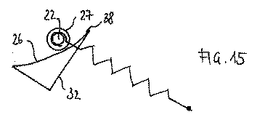
図11〜図15に本発明の第3の実施形態を示す。図は、事務椅子のための揺動機構1の諸部分を示している。ここでは本来の背もたれ支持体は破線で略示されている。背もたれ支持体5はコネクティングロッド62を介して座面支持体4の後端部12と接続されている。背もたれ支持体前端部14はベース支持体2とヒンジ状に接続されており、ベース支持体2はその前端部6で回転継手8を介して座面支持体前端部7に接続されている。座面支持体2には軸受ブロック32が揺動可能に取り付けられているが、図11には軸受ブロック32と座面支持体2の接続は図示しない。軸受ブロックの揺動軸38は、軸受ブロック32の後(上)端部37にある枢着部を通って延びている。詳述はしないが、種々のタイプの軸受ブロック32を使用することができる。しかしながら調節によって軸受ブロック前端部33は前方に揺動でき、その結果機構の「硬い」調整に至るが、これについて以下詳述する。
11 to 15 show a third embodiment of the present invention. The figure shows parts of the swing mechanism 1 for an office chair. Here, the original back support is schematically shown in broken lines. The
背もたれの調節力を調整するために、引張コイルばね63として形成されたばね要素を少なくとも1個備えたばね機構15が設けられている。以下の例では引張コイルばね63を1個のみ使用することを前提とする。しかし2個以上のばねを使用することもできる。引張コイルばね63は、留め輪又は開いたフックとして形成されたばね後端部64で、背もたれ支持体5の両アームの間に延びており背もたれ支持体5の一部と見なすことができるクロスピン65の中央に取り付けられている。これによりばね63は追加の連結要素なしに直接背もたれ支持体5と接続されている。同様に留め輪又は開いたフックとして形成されたばね前端部66は軸受ピン22と接続されている。この場合、ばね前端部66は本発明でいう作動要素として用いられる。軸受ピンは、上述した実施形態におけるように、その両端に玉軸受として形成された転がり軸受27を有しており、これらの軸受によって軸受ブロック32の軸受面26上に載っている(図16参照)。
In order to adjust the adjustment force of the backrest, a
引張コイルばね63が実質的に水平位置にある図12に示された初期ポジションにおいて、ピン22は軸受ブロック37の後(上)部領域で軸受面26上にある。背もたれ支持体5が揺動方向23で後下方へ揺動すると、ばね前端部66の位置が変化する。この位置の変化はばね66の伸張、従って揺動抵抗の変化を伴っている(図13参照)。同時にピン22がばね端部66によって連行されて、軸受面26上を軸受ブロック前(下)端部33に移動する。
In the initial position shown in FIG. 12 where the
図12及び図13に示された軸受ブロック32のポジションにおいて、凹状軸受面26によって画定される転動曲線は垂直線を基準として比較的平坦である。ばね63が揺動するとピン22は比較的強く偏移することができ、その結果としてばね63は比較的僅かしか伸張されない。この「柔らかい」調整においては、使用者が事務椅子の背もたれを後方へ揺動させることは比較的簡単である。即ち揺動抵抗は小さい。
12 and 13, the rolling curve defined by the
軸受ブロック32の位置が変化して軸受面26によって画定される転動曲線が垂直線を基準にして比較的急勾配になると(図14及び図15参照)、背もたれ支持体5の揺動により引き起されるピン22の偏移は比較的弱く(短く)、その結果ばね63は以前よりも強く伸張される。この「硬い」調整においては、使用者が事務椅子の背もたれを後方へ揺動させるのはより困難である。即ち揺動抵抗は大きい。ここでは背もたれ支持体5の揺動角は上述した実施形態と同様、軸受ブロック32の位置にかかわりなく常に等しい。本機構は、作動要素が常に等しく運動するように構成されている。
When the position of the
図16に事務椅子機構1に使用するために設けられた装置の詳細を示す。事務椅子機構1は、機能要素22を回転可能に支承するための2個の軸受27を備え転動体及び/又は滑動体として形成された位置可変な機能要素22と、軸受ブロック32の2個の凹状の軸受面26によって形成された、軸受27のための支持軌道及び/又は案内軌道を有する。
FIG. 16 shows details of an apparatus provided for use in the office chair mechanism 1. The office chair mechanism 1 includes two
図17〜図19に本発明の第4の実施形態を示す。これらの図は事務椅子1のための揺動機構の諸部材を示す。背もたれ支持体5は共通のコネクティングロッド67を介して、座面支持体4の後端部12とも、ベース支持体2の後端部68とも揺動可能に接続されている。ベース支持体2はその前端部6で第2のコネクティングロッド69を介して座面支持体7に接続されている。
17 to 19 show a fourth embodiment of the present invention. These figures show the members of the swing mechanism for the office chair 1. The
座面支持体2の構成要素70に軸受ブロック32が揺動可能に取り付けられている。軸受ブロック32の揺動軸38は軸受ブロック32の前(上)端部33にある枢着部を通って延びている。この場合、直線状である軸受ブロック32の軸受面26の傾きは、調節要素(図示せず)によって変化させることが可能である。それにより軸受ブロック37の後端部が座面支持体4に向かって上方へ揺動でき、その結果機構の「硬い」調整が得られるが、これについては以下詳述する。軸受面26は直線状ではなく、上述した実施形態におけるように凹状又は凸状に形成することもできる。
A bearing
背もたれの調節力を調整するために、引張コイルばね63として形成されたばね要素を少なくとも1個備えたばね機構15が設けられている。以下の例では、引張コイルばね63を1個のみ使用することを前提とする。しかし2個以上の平行に位置するばねを使用することもできる。引張コイルばね63は、留め輪又は開いたフックとして形成されたばね前端部66で、ベース支持体2の構成要素71の間に延びるクロスピン65に取り付けられている。同様に、留め輪又は開いたフックとして形成されているばね後端部64は軸受ピン22と接続されている。この場合、ばね後端部64は本発明でいう作動要素として用いられる。軸受ピン22は、上述した実施形態におけるように、その両端に玉軸受として形成された転がり軸受27を有しており、これらの軸受によって軸受ブロック32の軸受面26上に載っている。
In order to adjust the adjustment force of the backrest, a
軸受ピン22は連結要素72と揺動可能に接続されている。このために軸受ピン22は連結要素72の一方の端部で支承されている。連結要素72の反対側の端部は枢着部73で座面支持体4と揺動可能に接続されている。背もたれ支持体5が揺動方向23で後下方へ揺動すると、背もたれ支持体5に連結された座面支持体4も同様の方式で揺動する。それにより座面支持体4に設けた連結要素72の連結部73が運動し、その結果連結要素72を介して軸受ピン22のポジションと共に引張コイルばね63のポジションも変化する。従って座面支持体4は連結要素72と共に、ばね機構15を間接的に背もたれ支持体5に連結する働きをする。
The bearing
軸受面26の傾きは初期ポジション、即ち背もたれが揺動していない状態で調整される。可能な限り最良の「柔らかい」調整において、軸受ブロック32の後端部37はベース支持体2に当接している。軸受面26の水平線に対する角度は約60°である(図18参照)。「最も硬い」調整では軸受面26はほぼ水平である。この場合、直線状の軸受面26の水平線に対する角度は約10°である(図19参照)。初期ポジションにおいて軸受ピン22は軸受ブロック26の枢着点及び支承点38の近傍にあるので(図17参照)、傾きの調節、従ってばね力調整の調節はほとんど力を加えずに行われる。この場合、ばね63には最低限の応力しか掛からない。
The inclination of the bearing
図17に示した初期ポジションにおいて、ピン22は軸受面26のほぼ中央にある。背もたれ支持体5が揺動方向23で後下方へ揺動すると、ばね後端部64の位置は変化する。この位置変化はばね63の伸張と共に揺動抵抗の変化を伴う。同時にピン22は連結要素72によって連行されて、軸受面26上を軸受ブロック後端部37に向かって後方に移動する。
In the initial position shown in FIG. 17, the
図18に示す揺動ポジションにおいて、軸受面26によって画定される転動曲線は垂直線を基準として比較的平坦である。ばね63が揺動するとピン22は比較的強く偏移することができ、その結果としてばね63は比較的僅かしか伸張されない。この「柔らかい」調整において、使用者は事務椅子の背もたれを比較的簡単に後方へ揺動させることができる。即ち揺動抵抗は小さい。
In the swing position shown in FIG. 18, the rolling curve defined by the bearing
さて、軸受ブロック32の位置が変化して軸受面26によって画定される転動曲線が垂直線を基準にして比較的急勾配になると(図19参照)、背もたれ支持体5の揺動によりピン22はより強く背もたれ支持体5に向かって移動すると共に、ばね63はより強く伸張される。この「硬い」調整において、使用者が事務椅子の背もたれを後方へ揺動させるのはより困難である。即ち揺動抵抗が大きい。ここでは背もたれ支持体5の揺動角は上述した実施形態と同様、軸受ブロック32の位置にかかわりなく常に等しい。
Now, when the position of the
上述の実施形態において構成要素70、71の構成及び枢着部38、65の配置は、所望の揺動特性を調整するために、軸受ピン22のための曲線軌道26、並びに連結要素72の長さ及び配置と同様に可変である。
In the above-described embodiment, the configuration of the
本発明の個々の様相を以下再度詳細に説明する。 Individual aspects of the present invention are described in detail again below.
まず、ピン22が軸受27を備えておらず、直接軌道上に載っていると仮定する。ピン22が運動する軌道が曲線軌道ではなく直接軌道であって、ピン22上を転動する作動要素が常に軌道に対して平行に移動するならば、ピン22に対して偏移力が作用しないであろう。しかし事務椅子機構において作動要素は常に角運動を行う。それゆえピン22が不都合にも軌道から押し出されるのを所定の勾配によって妨げる曲線軌道が設けられる。
First, it is assumed that the
さて、作動要素がそのような軸受けされていないピン22の上に載っているような場合、作動要素が角運動するとピン22は最初常に転動運動を行うであろう。しかしながら曲線軌道26の勾配が急過ぎると、ピン22は転動するのを妨げられるであろう。ピン22の転動運動は滑り運動に移行し、それによってピン22と軌道に望ましくない摩耗をもたらすであろう。それゆえピン22に軸受27を備えて、これらの軸受内でピン22が自由に回転でき、それによって追加的な回転自由度を得るようにした。このようにすることにより上述の例における滑り摩擦への移行は効果的に回避される。
Now, if the actuating element rests on such a
次に、作動要素の作用を受けた機能要素の運動を図2及び図3に示した例に基づいて再度説明する。背もたれ支持体5が揺動して、ねじりコイルばね16の下部ばね脚18として形成された作動要素が、ピン22として形成された機能要素を支持点29で押圧すると、ばね脚18の角度変化を伴う。このばね脚18の位置変化により力の不均衡が生じて軌道上でのピン22の位置を変化させる。ピン22は軌道の曲線形状により再び力の平衡が生じるまでの間、斜めに当接するばね脚18から偏移する。ピン22は遅くとも、ばね脚18がピン22の軌道(軸受面26)との接点31を通るその都度の接線と平行になったときに停止する。この力の平衡は軌道が急勾配であればあるほど早く達成され、ピン22の偏移も僅かになる。ピン22の偏移が僅かであればあるほど−背もたれ支持体5の揺動が等しければ−ばね脚18の勾配は急になる。その結果、ばね16はより強く緊張される。言い換えれば、軸受ブロック32の位置変化、特に揺動と、それに伴う曲線軌道の変化により、機構1のばね力の挙動又は運動特性の他の特徴が調整され得る。
Next, the movement of the functional element subjected to the action of the operating element will be described again based on the example shown in FIGS. When the
しかし軸受ブロック32は基本的に使用目的に応じて固定して、即ち揺動不能又は傾倒不能に取り付けることもできる。しかしながらこのような場合には、ピン22の位置変化の少なくとも1個の特性を調整する可能性はなくなる。しかしこの場合でもばね機構15にすべり摩擦なしに応力が掛けられるので、機構1の摩耗は減少するであろう。
However, the bearing
軸受ブロック32の支承点のポジション、即ち揺動軸38の位置は可変である。支承点がピン22の軸から離れれば離れるほど、ばね機構15を調節する際により多くの応力が達成される。揺動軸38がピン22のポジションに近づけば近づくほど、ばね機構15によって生み出される応力は少なくなる。
The position of the bearing point of the
軌道は最も単純な場合は円弧部分の形状を有することができる。変形(最初平坦で後から急勾配になる等)も可能であり、その場合は別の動的ばね挙動が得られる。それによって機構は、顧客の要望に応じて、逓減的、直線的又は累進的な挙動を示すことができる。換言すれば軸受ブロック32の傾きの調整だけによらず、機構の運動特性を変化させることが可能である。これは軸受面26の凹状を変えることによっても、即ち曲線軌道の形状によっても可能である。この場合、曲線軌道は直線であってもよい。図17〜図19に示された実施形態を参照されたい。
The trajectory can have the shape of an arc portion in the simplest case. Deformation (such as initially flat and later steep) is also possible, in which case another dynamic spring behavior is obtained. This allows the mechanism to show decreasing, linear or progressive behavior depending on the customer's desire. In other words, it is possible to change the motion characteristics of the mechanism, not only by adjusting the inclination of the
前述の説明、以下の請求項及び図面に示された全ての特徴は単独でも、互いに任意に組み合わせても発明にとって本質的である。 All features set forth in the foregoing description, the following claims and the drawings are essential to the invention either singly or in any combination with one another.
1 揺動機構
2 ベース支持体
3 テーパ状受容部
4 座面支持体
5 背もたれ支持体
6 ベース支持体前端部
7 座面前端部
8 回転継手
9 主揺動軸
10 (なし)
11 椅子長手方向
12 座面後端部
13 支承部
14 背もたれ支持体前端部
15 ばね機構
16 ばね脚
17 上部ばね脚
18 下部ばね脚
19 下側
20 (なし)
21 (なし)
22 軸受ピン
23 揺動方向
24 角柱軸受
25 ばね軸
26 軸受面
27 転がり軸受け
28 ばね脚下側
29 第1の作用点
30 機能面
31 第2の作用点
32 軸受ブロック
33 軸受ブロック前端部
34 調節楔
35 切欠部
36 枢着部
37 軸受ブロック後端部
38 揺動軸
39 揺動方向
40 (なし)
41 自由端
42 ねじロッド
43 ハンドル
44 楔ナット
45 蟻継ぎガイド
46 接触面
47 (なし)
48 圧縮コイルばね
49 レバーアーム
50 ガイド側縁部
51 六角軸
52 保持脚部
53 保持脚部
54 ばね受け
55 ばね可動端
56 ばね固定端
57 ばね受け
58 ガイドロッド
59 保持脚部の回転継手
60 六角軸の枢着部
61 案内装置
62 コネクティングロッド
63 引張コイルばね
64 ばね後端部
65 クロスピン
66 ばね前端部
67 コネクティングロッド
68 ベース支持体後端部
69 コネクティングロッド
70 構成要素
71 構成要素
72 連結要素
73 枢着部
DESCRIPTION OF SYMBOLS 1
DESCRIPTION OF
21 (none)
22
41
48
Claims (16)
Applications Claiming Priority (7)
| Application Number | Priority Date | Filing Date | Title |
|---|---|---|---|
| DE102008010673 | 2008-02-22 | ||
| DE102008010673.9 | 2008-02-22 | ||
| DE102008027859 | 2008-06-11 | ||
| DE102008027859.9 | 2008-06-11 | ||
| DE102008045489A DE102008045489A1 (en) | 2008-02-22 | 2008-09-03 | Mechanics for an office chair |
| DE102008045489.3 | 2008-09-03 | ||
| PCT/EP2009/000336 WO2009103389A1 (en) | 2008-02-22 | 2009-01-21 | Mechanism for an office chair |
Publications (2)
| Publication Number | Publication Date |
|---|---|
| JP2011512210A JP2011512210A (en) | 2011-04-21 |
| JP5383710B2 true JP5383710B2 (en) | 2014-01-08 |
Family
ID=42813464
Family Applications (1)
| Application Number | Title | Priority Date | Filing Date |
|---|---|---|---|
| JP2010547069A Active JP5383710B2 (en) | 2008-02-22 | 2009-01-21 | Mechanism for office chair |
Country Status (7)
| Country | Link |
|---|---|
| US (1) | US8733839B2 (en) |
| EP (1) | EP2244605B1 (en) |
| JP (1) | JP5383710B2 (en) |
| AT (1) | ATE506876T1 (en) |
| CA (1) | CA2716042C (en) |
| DE (3) | DE202008011703U1 (en) |
| WO (1) | WO2009103389A1 (en) |
Families Citing this family (9)
| Publication number | Priority date | Publication date | Assignee | Title |
|---|---|---|---|---|
| DE102007022015A1 (en) * | 2006-10-13 | 2008-04-17 | Bock 1 Gmbh & Co. Kg | Mechanics for an office chair |
| CH701715A2 (en) * | 2009-08-26 | 2011-02-28 | Vitra Patente Ag | Chair mechanism. |
| US9060610B2 (en) * | 2011-11-11 | 2015-06-23 | Flexsteel Industries, Inc. | Spring back hinge with or without spring lock mechanism |
| DE202013100574U1 (en) | 2013-02-07 | 2014-05-08 | Bock 1 Gmbh & Co. Kg | Mechanics for an office chair |
| DE102013102007B4 (en) * | 2013-02-28 | 2023-05-04 | Bock 1 Gmbh & Co. Kg | Mechanics for an office chair |
| DE202013102059U1 (en) * | 2013-05-11 | 2014-08-12 | Bock 1 Gmbh & Co. Kg | synchronous mechanism |
| ITUB20154688A1 (en) * | 2015-10-15 | 2017-04-15 | Co Fe Mo Ind S R L | OSCILLATION MECHANISM FOR ADJUSTABLE CHAIRS |
| WO2019204714A1 (en) | 2018-04-19 | 2019-10-24 | Cramer Llc | Chair having pliable backrest and methods for same |
| CN108371436B (en) * | 2018-04-25 | 2023-10-27 | 严澄宇 | Elastic seesaw type free tilting mechanism and free adjusting swivel chair |
Family Cites Families (12)
| Publication number | Priority date | Publication date | Assignee | Title |
|---|---|---|---|---|
| US4494795A (en) * | 1982-05-06 | 1985-01-22 | Steelcase Inc. | Variable back adjuster for chairs |
| JPH0531966Y2 (en) | 1988-08-22 | 1993-08-17 | ||
| JPH085637Y2 (en) | 1990-12-26 | 1996-02-21 | 株式会社イトーキクレビオ | Chair tilt controller |
| JP2919131B2 (en) | 1991-10-22 | 1999-07-12 | 株式会社イトーキクレビオ | Chair tilt control device |
| DE4341071A1 (en) | 1993-12-02 | 1995-06-08 | Hansen Fritz As | Office chair with adjustable lumbar support suspension |
| JPH07289383A (en) | 1994-04-27 | 1995-11-07 | Tokai Kinzoku Kogyo Kk | Reclining device for chair |
| US5909924A (en) * | 1997-04-30 | 1999-06-08 | Haworth, Inc. | Tilt control for chair |
| AU2001245735A1 (en) * | 2000-03-17 | 2001-10-03 | Herman Miller, Inc. | Tilt assembly for a chair |
| EP1175854A1 (en) | 2000-07-25 | 2002-01-30 | CO.FE.MO. S.p.A. | Adjustment device for inclinable office chair and the like |
| EP1228722B1 (en) | 2001-04-27 | 2002-08-14 | CO.FE.MO. S.p.A. | Elastic support device for inclinable portions of office chairs and the like |
| DE102005020237B3 (en) | 2005-04-28 | 2006-08-17 | Bock 1 Gmbh & Co. Kg | Synchronous mechanism e.g. for correlated seat backrest movement of office chair, is connected to chair column base carrier, seat support and backrest carrier with tiltable backrest carrier arranged around transverse axis |
| DE102007022015A1 (en) | 2006-10-13 | 2008-04-17 | Bock 1 Gmbh & Co. Kg | Mechanics for an office chair |
-
2008
- 2008-09-03 DE DE202008011703U patent/DE202008011703U1/en not_active Expired - Lifetime
- 2008-09-03 DE DE102008045489A patent/DE102008045489A1/en not_active Withdrawn
-
2009
- 2009-01-21 US US12/918,888 patent/US8733839B2/en active Active
- 2009-01-21 AT AT09713332T patent/ATE506876T1/en active
- 2009-01-21 EP EP09713332A patent/EP2244605B1/en active Active
- 2009-01-21 CA CA2716042A patent/CA2716042C/en active Active
- 2009-01-21 DE DE502009000600T patent/DE502009000600D1/en active Active
- 2009-01-21 WO PCT/EP2009/000336 patent/WO2009103389A1/en active Application Filing
- 2009-01-21 JP JP2010547069A patent/JP5383710B2/en active Active
Also Published As
| Publication number | Publication date |
|---|---|
| DE502009000600D1 (en) | 2011-06-09 |
| DE102008045489A1 (en) | 2009-09-03 |
| CA2716042A1 (en) | 2009-08-27 |
| DE202008011703U1 (en) | 2009-07-02 |
| ATE506876T1 (en) | 2011-05-15 |
| EP2244605B1 (en) | 2011-04-27 |
| US20110012409A1 (en) | 2011-01-20 |
| JP2011512210A (en) | 2011-04-21 |
| WO2009103389A1 (en) | 2009-08-27 |
| CA2716042C (en) | 2014-07-08 |
| EP2244605A1 (en) | 2010-11-03 |
| US8733839B2 (en) | 2014-05-27 |
Similar Documents
| Publication | Publication Date | Title |
|---|---|---|
| JP5383710B2 (en) | Mechanism for office chair | |
| KR102307892B1 (en) | Chair with adjustable backrest | |
| JP5643819B2 (en) | Chair backrest reaction mechanism and chair incorporating the same | |
| US20070040432A1 (en) | Synchronisation mechanism for chairs or armchairs | |
| US9277821B2 (en) | Tilt mechanism for a chair and chair | |
| US8985688B2 (en) | Office chair mechanism provided with a device for adjusting the swivel force | |
| BRPI0609652B1 (en) | reclining force adjustment device for office chair mechanisms | |
| KR20130038121A (en) | Device for synchronizing the seat and backrest of a chair | |
| KR102104462B1 (en) | Chair assembly having multi limited tilting function and chair including the same | |
| JP2018047284A (en) | Mechanism for office chair | |
| KR20160141740A (en) | Device for synchronizing the tilt of the backrest and the seat of a chair | |
| JP2019188126A (en) | Elastic seesaw type free reclining mechanism, and freely adjustable swivel chair | |
| JP2002010852A (en) | Chair having seat and backrest rocking simultaneously | |
| JP2008535592A (en) | Device for adjusting the seat inclination of a chair | |
| KR101952033B1 (en) | Adjusting tilt-range device of chair | |
| JP3974425B2 (en) | Reclining chair | |
| CN211748206U (en) | Chassis of office chair | |
| JP4754680B2 (en) | Tilt range adjustment device for backrest in chair | |
| JP3807993B2 (en) | Reclining chair | |
| US7316453B2 (en) | Chair spring tension control | |
| CN106165986B (en) | Damping adjustment mechanism and base link gear of seat back link chair | |
| JP4754679B2 (en) | Tilt range adjustment device for backrest in chair | |
| US7125078B2 (en) | Device for the adjustment of the compression force of the spring in an articulation for a chair | |
| KR102083157B1 (en) | Device for alternately tilting chair | |
| JP4142538B2 (en) | Chair recliner |
Legal Events
| Date | Code | Title | Description |
|---|---|---|---|
| A977 | Report on retrieval |
Free format text: JAPANESE INTERMEDIATE CODE: A971007 Effective date: 20120920 |
|
| A131 | Notification of reasons for refusal |
Free format text: JAPANESE INTERMEDIATE CODE: A131 Effective date: 20121002 |
|
| A601 | Written request for extension of time |
Free format text: JAPANESE INTERMEDIATE CODE: A601 Effective date: 20121227 |
|
| A602 | Written permission of extension of time |
Free format text: JAPANESE INTERMEDIATE CODE: A602 Effective date: 20130109 |
|
| A601 | Written request for extension of time |
Free format text: JAPANESE INTERMEDIATE CODE: A601 Effective date: 20130201 |
|
| A602 | Written permission of extension of time |
Free format text: JAPANESE INTERMEDIATE CODE: A602 Effective date: 20130208 |
|
| A521 | Request for written amendment filed |
Free format text: JAPANESE INTERMEDIATE CODE: A523 Effective date: 20130304 |
|
| TRDD | Decision of grant or rejection written | ||
| A01 | Written decision to grant a patent or to grant a registration (utility model) |
Free format text: JAPANESE INTERMEDIATE CODE: A01 Effective date: 20130910 |
|
| A61 | First payment of annual fees (during grant procedure) |
Free format text: JAPANESE INTERMEDIATE CODE: A61 Effective date: 20131001 |
|
| R150 | Certificate of patent or registration of utility model |
Ref document number: 5383710 Country of ref document: JP Free format text: JAPANESE INTERMEDIATE CODE: R150 Free format text: JAPANESE INTERMEDIATE CODE: R150 |
|
| R250 | Receipt of annual fees |
Free format text: JAPANESE INTERMEDIATE CODE: R250 |
|
| R250 | Receipt of annual fees |
Free format text: JAPANESE INTERMEDIATE CODE: R250 |
|
| R250 | Receipt of annual fees |
Free format text: JAPANESE INTERMEDIATE CODE: R250 |
|
| R250 | Receipt of annual fees |
Free format text: JAPANESE INTERMEDIATE CODE: R250 |
|
| R250 | Receipt of annual fees |
Free format text: JAPANESE INTERMEDIATE CODE: R250 |
|
| R250 | Receipt of annual fees |
Free format text: JAPANESE INTERMEDIATE CODE: R250 |
|
| R250 | Receipt of annual fees |
Free format text: JAPANESE INTERMEDIATE CODE: R250 |
|
| R250 | Receipt of annual fees |
Free format text: JAPANESE INTERMEDIATE CODE: R250 |