JP5382440B2 - Valve timing control device - Google Patents
Valve timing control device Download PDFInfo
- Publication number
- JP5382440B2 JP5382440B2 JP2009220652A JP2009220652A JP5382440B2 JP 5382440 B2 JP5382440 B2 JP 5382440B2 JP 2009220652 A JP2009220652 A JP 2009220652A JP 2009220652 A JP2009220652 A JP 2009220652A JP 5382440 B2 JP5382440 B2 JP 5382440B2
- Authority
- JP
- Japan
- Prior art keywords
- phase
- rotating member
- side rotating
- relative
- retarded
- Prior art date
- Legal status (The legal status is an assumption and is not a legal conclusion. Google has not performed a legal analysis and makes no representation as to the accuracy of the status listed.)
- Expired - Fee Related
Links
Images


Classifications
-
- F—MECHANICAL ENGINEERING; LIGHTING; HEATING; WEAPONS; BLASTING
- F01—MACHINES OR ENGINES IN GENERAL; ENGINE PLANTS IN GENERAL; STEAM ENGINES
- F01L—CYCLICALLY OPERATING VALVES FOR MACHINES OR ENGINES
- F01L1/00—Valve-gear or valve arrangements, e.g. lift-valve gear
- F01L1/34—Valve-gear or valve arrangements, e.g. lift-valve gear characterised by the provision of means for changing the timing of the valves without changing the duration of opening and without affecting the magnitude of the valve lift
- F01L1/344—Valve-gear or valve arrangements, e.g. lift-valve gear characterised by the provision of means for changing the timing of the valves without changing the duration of opening and without affecting the magnitude of the valve lift changing the angular relationship between crankshaft and camshaft, e.g. using helicoidal gear
- F01L1/3442—Valve-gear or valve arrangements, e.g. lift-valve gear characterised by the provision of means for changing the timing of the valves without changing the duration of opening and without affecting the magnitude of the valve lift changing the angular relationship between crankshaft and camshaft, e.g. using helicoidal gear using hydraulic chambers with variable volume to transmit the rotating force
-
- F—MECHANICAL ENGINEERING; LIGHTING; HEATING; WEAPONS; BLASTING
- F01—MACHINES OR ENGINES IN GENERAL; ENGINE PLANTS IN GENERAL; STEAM ENGINES
- F01L—CYCLICALLY OPERATING VALVES FOR MACHINES OR ENGINES
- F01L1/00—Valve-gear or valve arrangements, e.g. lift-valve gear
- F01L1/02—Valve drive
- F01L1/04—Valve drive by means of cams, camshafts, cam discs, eccentrics or the like
- F01L1/047—Camshafts
- F01L2001/0478—Torque pulse compensated camshafts
-
- F—MECHANICAL ENGINEERING; LIGHTING; HEATING; WEAPONS; BLASTING
- F01—MACHINES OR ENGINES IN GENERAL; ENGINE PLANTS IN GENERAL; STEAM ENGINES
- F01L—CYCLICALLY OPERATING VALVES FOR MACHINES OR ENGINES
- F01L1/00—Valve-gear or valve arrangements, e.g. lift-valve gear
- F01L1/34—Valve-gear or valve arrangements, e.g. lift-valve gear characterised by the provision of means for changing the timing of the valves without changing the duration of opening and without affecting the magnitude of the valve lift
- F01L1/344—Valve-gear or valve arrangements, e.g. lift-valve gear characterised by the provision of means for changing the timing of the valves without changing the duration of opening and without affecting the magnitude of the valve lift changing the angular relationship between crankshaft and camshaft, e.g. using helicoidal gear
- F01L1/3442—Valve-gear or valve arrangements, e.g. lift-valve gear characterised by the provision of means for changing the timing of the valves without changing the duration of opening and without affecting the magnitude of the valve lift changing the angular relationship between crankshaft and camshaft, e.g. using helicoidal gear using hydraulic chambers with variable volume to transmit the rotating force
- F01L2001/3445—Details relating to the hydraulic means for changing the angular relationship
- F01L2001/34453—Locking means between driving and driven members
-
- F—MECHANICAL ENGINEERING; LIGHTING; HEATING; WEAPONS; BLASTING
- F01—MACHINES OR ENGINES IN GENERAL; ENGINE PLANTS IN GENERAL; STEAM ENGINES
- F01L—CYCLICALLY OPERATING VALVES FOR MACHINES OR ENGINES
- F01L1/00—Valve-gear or valve arrangements, e.g. lift-valve gear
- F01L1/34—Valve-gear or valve arrangements, e.g. lift-valve gear characterised by the provision of means for changing the timing of the valves without changing the duration of opening and without affecting the magnitude of the valve lift
- F01L1/344—Valve-gear or valve arrangements, e.g. lift-valve gear characterised by the provision of means for changing the timing of the valves without changing the duration of opening and without affecting the magnitude of the valve lift changing the angular relationship between crankshaft and camshaft, e.g. using helicoidal gear
- F01L1/3442—Valve-gear or valve arrangements, e.g. lift-valve gear characterised by the provision of means for changing the timing of the valves without changing the duration of opening and without affecting the magnitude of the valve lift changing the angular relationship between crankshaft and camshaft, e.g. using helicoidal gear using hydraulic chambers with variable volume to transmit the rotating force
- F01L2001/3445—Details relating to the hydraulic means for changing the angular relationship
- F01L2001/34483—Phaser return springs
Description
本発明は、内燃機関のクランクシャフトに対して同期回転する駆動側回転部材と、駆動側回転部材に対して同軸上に配置され、内燃機関の吸気弁及び排気弁の少なくとも一方を開閉するカムシャフトに対して一体回転する従動側回転部材と、駆動側回転部材と従動側回転部材の間の相対位相を、可動する仕切りによって容積が相補に可変する2種類の圧力室のそれぞれに対する作動流体の給排によって変位させる位相変換機構とを有する弁開閉時期制御装置に関する。 The present invention relates to a drive-side rotating member that rotates synchronously with a crankshaft of an internal combustion engine, and a camshaft that is arranged coaxially with respect to the drive-side rotating member and opens and closes at least one of an intake valve and an exhaust valve of the internal combustion engine. The working fluid is supplied to each of the two types of pressure chambers whose volumes can be complementarily varied by a movable partition with respect to the driven side rotating member that rotates integrally with the driven side rotating member and the relative phase between the driving side rotating member and the driven side rotating member. The present invention relates to a valve opening / closing timing control device having a phase conversion mechanism that is displaced by exhaust.
この種の弁開閉時期制御装置に関連する先行技術文献情報として下記に示す特許文献1がある。この特許文献1に記された弁開閉時期制御装置は、必要に応じて相対位相を内燃機関の始動に適した中間位相にロックすることの可能なロック機構を備えている。このロック機構は、従動側回転部材に形成されたロック溝と、このロック溝に対して係入可能なように駆動側回転部材に移動可能に支持されたロックピンとを有し、ロックピンはロック溝に係入する方向にバネによって付勢されている。両回転部材の相対位相が中間位相に達すると、ロックピンは同バネの付勢力によって自動的にロック溝に入り込むように構成されている。内燃機関の始動完了後は、一般に、ロック機構によるロックをオイルポンプなどで供給されるオイルの圧力によって解除し、やはりオイルの圧力によって中間位相から進角側へ変位させる操作が行われる。
As prior art document information related to this type of valve opening / closing timing control device, there is
また、一般に、弁開閉時期制御装置では、吸気弁や排気弁のバルブスプリングから受けるカム反力により、従動側回転部材が駆動側回転部材に対して遅れがちになる傾向を抑制するための手段として、相対位相を中間位相の方向へ付勢するトーションバネなどの付勢機構が設けられている場合が多い。特に、特許文献1に記された弁開閉時期制御装置のトーションバネは、その付勢機能が中間位相より遅角位相方向側に位置する中間規制位相と最遅角位相の間に限定されており、進角位相と中間位相の間の領域では付勢機能が効かないので、進角位相から中間位相や中間規制位相への変位操作が、カム反力およびポンプによる油圧力によって迅速に行われる。
Further, in general, in the valve opening / closing timing control device, as a means for suppressing the tendency that the driven side rotating member tends to be delayed with respect to the driving side rotating member due to the cam reaction force received from the valve spring of the intake valve or the exhaust valve. In many cases, a biasing mechanism such as a torsion spring that biases the relative phase toward the intermediate phase is provided. In particular, the torsion spring of the valve opening / closing timing control device described in
しかし、特許文献1に記された弁開閉時期制御装置では、中間位相へのロック操作は、中間位相に達した際のロックピンの進入動作に依存しているため、例えばオイル内などに存在する異物によってロックピンの動きが妨げられるとロックピンがロック溝に確実に係入されず、中間位相へのロックが十分に行われない虞があった。
However, in the valve opening / closing timing control device described in
また、中間位相での内燃機関の始動完了後、相対位相を進角位置へ移行させるために中間位相から脱出させるには、ロックピンをロック溝から押出すためにオイルを供給するなどの機構が必要なため、弁開閉時期制御装置がより大型化し、複雑化する傾向があった。 In addition, after the start of the internal combustion engine in the intermediate phase, in order to escape from the intermediate phase in order to shift the relative phase to the advanced position, a mechanism such as supplying oil to push the lock pin out of the lock groove is used. Since it is necessary, the valve timing control device tends to be larger and complicated.
そこで、本発明の目的は、上に例示した従来技術による弁開閉時期制御装置が与える課題に鑑み、異物の存在などに左右されることなく中間位相への保持が有効に実現される弁開閉時期制御装置を提供することにある。また、本発明の別の目的は、機構的により単純で故障し難く、しかも小型化し易い弁開閉時期制御装置を提供することにある。 Accordingly, an object of the present invention is to provide a valve opening / closing timing at which an intermediate phase can be effectively maintained without being affected by the presence of foreign matter, in view of the problems given by the conventional valve opening / closing timing control device exemplified above. It is to provide a control device. Another object of the present invention is to provide a valve opening / closing timing control device that is mechanically simpler, less likely to fail, and easy to downsize.
本発明による弁開閉時期制御装置の特徴構成は、
内燃機関のクランクシャフトに対して同期回転する駆動側回転部材と、
前記駆動側回転部材に対して同軸上に配置され、前記内燃機関の吸気弁及び排気弁の少なくとも一方を開閉するカムシャフトに対して一体回転する従動側回転部材と、
前記駆動側回転部材と前記従動側回転部材の間の相対位相を、可動する仕切りによって容積が相補に可変する2種類の圧力室のそれぞれに対する作動流体の給排によって進角位相側または遅角位相側に変位させる位相変換機構と、
前記相対位相を最進角位相及び最遅角位相を除く前記内燃機関の始動に適した所定位相に向けて付勢する付勢部材と、を有し、前記付勢部材は、前記相対位相を進角位相方向へ付勢する第1付勢部材と前記相対位相を遅角位相方向へ付勢する第2付勢部材とを有し、さらに、前記第1付勢部材による付勢力を前記所定位相と最遅角位相の間に限定する第1規制部と、前記第2付勢部材による付勢力を前記所定位相と最進角位相の間に限定する第2規制部とを備えている点にある。
FEATURES configuration of a valve timing control apparatus according to the present invention,
A drive-side rotating member that rotates synchronously with the crankshaft of the internal combustion engine;
A driven-side rotating member that is coaxially disposed with respect to the driving-side rotating member and rotates integrally with a camshaft that opens and closes at least one of an intake valve and an exhaust valve of the internal combustion engine;
The relative phase between the driving side rotating member and the driven side rotating member is set to an advance phase phase or a retard angle phase depending on supply / discharge of working fluid to / from each of the two types of pressure chambers whose volumes are complementarily variable by a movable partition. A phase conversion mechanism to be displaced to the side,
Have a, a biasing member for biasing the relative phase to a predetermined phase suitable for startup of the internal combustion engine except for a most advanced angle phase and the most retarded angle phase, the biasing member, the relative phase A first urging member for urging in the advance phase direction and a second urging member for urging the relative phase in the retard phase direction; and further, the urging force by the first urging member is the predetermined force A first restricting portion that limits between the phase and the most retarded angle phase; and a second restricting portion that limits the biasing force by the second biasing member between the predetermined phase and the most advanced angle phase. It is in.
すなわち、本発明の特徴構成による弁開閉時期制御装置では、一方の回転部材に形成されたロック溝と、他方の回転部材に支持されたロックピンなどで構成されたロック機構を備えず、代わりに、相対位相を最進角位相及び最遅角位相を除く内燃機関の始動に適した所定位相(始動最適位相)に向けて付勢する付勢部材を有する。したがって、作動油からの力のない状態では、相対位相が付勢部材の働きによって始動最適位相に変位される。したがって、オイル内の異物によってロックピンの動きが妨げられる等の問題がないため、付勢部材によって始動最適位相への保持が常に安定的に実現される。 That is, in the valve timing control device according to feature structure of the present invention is not provided with one rotary member formed lock groove, a locking mechanism which is configured by an other of the locking pin supported by the rotation member, instead And an urging member for urging the relative phase toward a predetermined phase (starting optimum phase) suitable for starting the internal combustion engine excluding the most advanced angle phase and the most retarded angle phase. Therefore, in a state where there is no force from the hydraulic oil, the relative phase is displaced to the optimum starting phase by the action of the biasing member. Therefore, since there is no problem that the movement of the lock pin is hindered by foreign matter in the oil, the urging member can always stably hold the start phase optimally.
また、ロック機構が、一方の回転部材に形成されたロック溝と、他方の回転部材に支持されたロックピンなどではなく、駆動側回転部材と従動側回転部材との間に介装された付勢部材で構成されているので、機構的に単純で故障し難い弁開閉時期制御装置が得られ、また、弁開閉時期制御装置を小型化し易くなる。
さらに、ロック溝への係入と離脱を交互に行うロックピンによるロック機構を備えないので、内燃機関の始動時にロック機構による異音が生じない。
In addition, the lock mechanism is not a lock groove formed on one rotating member and a lock pin supported on the other rotating member, but is attached between the driving side rotating member and the driven side rotating member. Since it is composed of a biasing member, a valve opening / closing timing control device that is mechanically simple and difficult to break down can be obtained, and the valve opening / closing timing control device can be easily downsized.
Further, since there is no lock mechanism using a lock pin that alternately engages and disengages from the lock groove, no noise is generated by the lock mechanism when the internal combustion engine is started.
最進角位相側から最遅角位相側までの領域において相対位相を所定位相に向けて付勢する付勢部材は、例えば、外力が働かない状況で相対位相を所定位相に付勢する1本のトーションバネ(付勢部材)などによっても構成することが可能である。しかし、この構成では、付勢部材の付勢力は同所定位相の近傍において最も弱くなるために、所定位相への安定的な保持が困難となり易い。また、所定位相から最進角位相側または最遅角位相側へと離れるに従って付勢部材の復元力は高まるので、付勢部材の付勢力に抗して相対位相を変位させるために大きな油圧力が必要となり、エネルギー損失が大きくなり易い。 The biasing member that biases the relative phase toward the predetermined phase in the region from the most advanced angle phase side to the most retarded angle phase side is, for example, one that biases the relative phase to the predetermined phase when no external force is applied. The torsion spring (biasing member) can also be used. However, in this configuration, since the urging force of the urging member becomes the weakest in the vicinity of the predetermined phase, it is difficult to stably hold the predetermined phase. In addition, since the restoring force of the urging member increases as it moves away from the predetermined phase toward the most advanced phase or the most retarded phase, a large hydraulic pressure is used to displace the relative phase against the urging force of the urging member. Is required, and energy loss tends to increase.
しかし、本構成のように、互いに付勢する向きが逆の2つの付勢部材とし、2つの付勢部材からの作用力が協働して相対位相を所定位相に付勢する構成とすれば、例えば、前述の1本のトーションバネ(付勢部材)などを設ける構成に比して、安定して所定位相に保持できる。 However, as in this configuration, if two biasing members having opposite biasing directions are used, and the acting force from the two biasing members cooperates, the relative phase is biased to a predetermined phase. For example, as compared with the configuration in which the one torsion spring (biasing member) described above is provided, the phase can be stably maintained at a predetermined phase.
また、本構成では、油圧操作などによって相対位相を前記所定位相から遅角位相側または進角位相側に操作する際に、例えば、遅角位相側に操作する際には第2付勢部材の付勢力は第2規制部によって所定位相と最進角位相の間に限定されているという具合に、常に一方の付勢部材の付勢力のみが作用するだけなので、比較的小さな油圧力で変位させることができる。 Further, in this configuration, when the relative phase is operated from the predetermined phase to the retarded phase side or the advanced phase side by hydraulic operation or the like, for example, when operated to the retarded phase side, the second biasing member Since the urging force is limited between the predetermined phase and the most advanced angle phase by the second restricting portion, only the urging force of one of the urging members always acts, so that the urging force is displaced with a relatively small oil pressure. be able to.
さらに、本構成では、各規制部によって、第1付勢部材による付勢力は所定位相と最遅角位相の間に限定され、第2付勢部材による付勢力は所定位相と最進角位相の間に限定されるので、相対位相を変位操作するための油圧などがない状態では、前記所定位相が、第1付勢部材による所定位相よりも進角位相側への付勢力が第1規制部によって規制され、第2付勢部材による所定位相よりも遅角位相側への付勢力が第2規制部によって規制された状態で実現される。その結果、付勢部材の製作精度の誤差などによって2つの付勢力が均等でない場合でも、相対位相が同誤差によって遅角位相側または進角位相側にずれることなく、当初の所定位相に制御され易い。 Further, in this configuration, the urging force by the first urging member is limited between the predetermined phase and the most retarded angle phase by each restricting portion, and the urging force by the second urging member is between the predetermined phase and the most advanced angle phase. Therefore, in the state where there is no hydraulic pressure for displacing the relative phase, the predetermined phase is such that the biasing force toward the advance phase side from the predetermined phase by the first biasing member is the first restricting portion. This is realized in a state where the urging force to the retarded phase side from the predetermined phase by the second urging member is regulated by the second regulating unit. As a result, even if the two biasing forces are not equal due to errors in the manufacturing accuracy of the biasing member, the relative phase is controlled to the initial predetermined phase without shifting to the retarded phase side or the advanced phase side due to the same error. easy.
本発明の他の特徴構成は、前記付勢部材が、前記カムシャフトのトルク変動に基づき前記従動側回転部材に作用する変位力に対抗する付勢力を有する点にある。 Another feature of the present invention is that the urging member has an urging force that opposes a displacement force that acts on the driven-side rotating member based on a torque fluctuation of the camshaft.
本構成であれば、付勢部材の付勢力が、カムシャフトのトルク変動に基づき従動側回転部材に作用する変位力を相殺する傾向になるので、付勢部材による相対位相の所定位相への保持精度が高められ、さらに、油圧による相対位相の制御精度が向上する。 With this configuration, the biasing force of the biasing member tends to cancel the displacement force acting on the driven side rotation member based on the torque fluctuation of the camshaft, so that the relative phase is maintained at the predetermined phase by the biasing member. The accuracy is increased, and the relative phase control accuracy by hydraulic pressure is improved.
本発明の他の特徴構成は、前記付勢部材が前記駆動側回転部材と前記従動側回転部材との間に配置されたスプリングである点にある。 Another characteristic configuration of the present invention is that the biasing member is a spring disposed between the driving side rotating member and the driven side rotating member.
本構成であれば、互いに隣接配置した駆動側回転部材と従動側回転部材の間に、トーションスプリング、ゼンマイバネなどのスプリングを配置するという簡単な構成の付勢部材によって本発明を実施することができ、弁開閉時期制御装置の組み立て作業が容易となり、小型化も容易となる。 With this configuration, the present invention can be implemented by a biasing member having a simple configuration in which a spring such as a torsion spring or a spring spring is disposed between the driving side rotating member and the driven side rotating member that are arranged adjacent to each other. As a result, the assembly operation of the valve opening / closing timing control device is facilitated, and the miniaturization is facilitated.
本発明による弁開閉時期制御装置の特徴構成は、
内燃機関のクランクシャフトに対して同期回転する駆動側回転部材と、
前記駆動側回転部材に対して同軸上に配置され、前記内燃機関の吸気弁及び排気弁の少なくとも一方を開閉するカムシャフトに対して一体回転する従動側回転部材と、
前記駆動側回転部材と前記従動側回転部材とにより形成され、容積が拡大することにより前記駆動側回転部材に対する前記従動側回転部材の相対位相を遅角方向に移動させる遅角室、及び、容積が拡大することにより前記相対位相を進角方向に移動させる進角室と、
前記相対位相を最進角位相及び最遅角位相を除く所定位相に向けて付勢する付勢部材と、を有し、
前記付勢部材は、前記相対位相を最遅角位相よりも進角位相方向側に位置する第1所定位相へ付勢する第1付勢部材と前記相対位相を最進角位相よりも遅角位相方向側に位置する第2所定位相へ付勢する第2付勢部材とを有し、
前記第1付勢部材は、前記相対位相を最遅角位相から前記第1所定位相まで付勢すると共に前記第1所定位相から最進角位相までは付勢せず、
前記第2付勢部材は、前記相対位相を最進角位相から前記第2所定位相まで付勢すると共に前記第2所定位相から最遅角位相までは付勢しない点にある。
FEATURES configuration of a valve timing control apparatus according to the present invention,
A drive-side rotating member that rotates synchronously with the crankshaft of the internal combustion engine;
A driven-side rotating member that is coaxially disposed with respect to the driving-side rotating member and rotates integrally with a camshaft that opens and closes at least one of an intake valve and an exhaust valve of the internal combustion engine;
A retarding chamber formed by the drive-side rotating member and the driven-side rotating member, and moving the relative phase of the driven-side rotating member with respect to the driving-side rotating member in the retarding direction by increasing the volume, and a volume An advance chamber that moves the relative phase in the advance direction by expanding
Have a, a biasing member for biasing the relative phase to a predetermined phase except for a most advanced angle phase and the most retarded angle phase,
The urging member includes a first urging member that urges the relative phase to a first predetermined phase that is positioned on the advance phase direction side of the most retarded phase, and the relative phase that is retarded from the most advanced angle phase. A second biasing member that biases to a second predetermined phase located on the phase direction side,
The first biasing member biases the relative phase from the most retarded phase to the first predetermined phase and does not bias from the first predetermined phase to the most advanced angle phase.
The second biasing member is in a point that biases the relative phase from the most advanced angle phase to the second predetermined phase and does not bias from the second predetermined phase to the most retarded phase .
すなわち、本発明の特徴構成による弁開閉時期制御装置では、一方の回転部材に形成されたロック溝と、他方の回転部材に支持されたロックピンなどで構成されたロック機構を備えず、代わりに、相対位相を最進角位相及び最遅角位相を除く所定位相に向けて付勢する付勢部材を有する。したがって、作動油からの力のない状態では、相対位相が付勢部材の働きによって所定位相に変位される。したがって、オイル内の異物によってロックピンの動きが妨げられる等の問題がないため、付勢部材によって所定位相(例えば始動最適位相)への保持が常に安定的に実現される。 That is, in the valve timing control device according to feature structure of the present invention is not provided with one rotary member formed lock groove, a locking mechanism which is configured by an other of the locking pin supported by the rotation member, instead And an urging member for urging the relative phase toward a predetermined phase excluding the most advanced angle phase and the most retarded angle phase. Therefore, in a state where there is no force from the hydraulic oil, the relative phase is displaced to a predetermined phase by the action of the urging member. Accordingly, there is no problem that the movement of the lock pin is hindered by the foreign matter in the oil, so that the holding to the predetermined phase (for example, the optimum starting phase) is always stably realized by the biasing member.
最進角位相側から最遅角位相側までの領域において相対位相を所定位相に向けて付勢する付勢部材は、例えば、1本のトーションバネなどによっても構成することが可能である。しかし、この構成では、付勢部材の付勢力は同所定位相の近傍において最も弱くなるために、所定位相への安定的な保持が困難となり易い。また、所定位相から最進角位相側または最遅角位相側へと離れるに従って付勢部材の復元力は高まるので、付勢部材の付勢力に抗して相対位相を変位させるために大きな油圧力が必要となり、エネルギー損失が大きくなり易い。 The urging member that urges the relative phase toward the predetermined phase in the region from the most advanced angle phase side to the most retarded angle phase side can be configured by, for example, a single torsion spring. However, in this configuration, since the urging force of the urging member becomes the weakest in the vicinity of the predetermined phase, it is difficult to stably hold the predetermined phase. In addition, since the restoring force of the urging member increases as it moves away from the predetermined phase toward the most advanced phase or the most retarded phase, a large hydraulic pressure is used to displace the relative phase against the urging force of the urging member. Is required, and energy loss tends to increase.
本構成のように、互いに付勢する向きが逆の2つの付勢部材とし、2つの付勢部材からの作用力が協働して相対位相を所定位相に付勢する構成とすれば、例えば、前述の1本のトーションバネなどを設ける構成に比して、安定して所定位相に保持できる。 As in this configuration, if two biasing members having opposite biasing directions are used, and the acting force from the two biasing members cooperates to bias the relative phase to a predetermined phase, for example, Compared to the configuration in which the one torsion spring or the like is provided, the predetermined phase can be stably maintained.
また、本構成では、油圧操作などによって相対位相を前記所定位相から遅角位相側または進角位相側に操作する際に、例えば、遅角位相側に操作する際には第2付勢部材の付勢力は第2規制部によって所定位相と最進角位相の間に限定されているという具合に、常に一方の付勢部材の付勢力のみが作用するだけなので、比較的小さな油圧力で変位させることができる。 Further, in this configuration, when the relative phase is operated from the predetermined phase to the retarded phase side or the advanced phase side by hydraulic operation or the like, for example, when operated to the retarded phase side, the second biasing member Since the urging force is limited between the predetermined phase and the most advanced angle phase by the second restricting portion, only the urging force of one of the urging members always acts, so that the urging force is displaced with a relatively small oil pressure. be able to.
さらに、本構成では、相対位相を変位操作するための油圧などが働かない状態では、第1付勢部は第1所定位相から最進角位相までは所定位相を付勢せず、第2付勢部材は第2所定位相から最遅角位相側までは所定位相を付勢しない。その結果、付勢部材の製作精度の誤差などによって2つの付勢力が均等でない場合でも、相対位相が同誤差によって遅角位相側または進角位相側にずれることなく、当初の所定位相に制御され易い。 Further, in this configuration, when the hydraulic pressure for operating the relative phase is not operated, the first urging unit does not urge the predetermined phase from the first predetermined phase to the most advanced angle phase. The biasing member does not bias the predetermined phase from the second predetermined phase to the most retarded phase side. As a result, even if the two biasing forces are not equal due to errors in the manufacturing accuracy of the biasing member, the relative phase is controlled to the initial predetermined phase without shifting to the retarded phase side or the advanced phase side due to the same error. easy.
以下に本発明を実施するための形態について図面を参照しながら説明する。
(第1実施形態)
〔基本構成〕
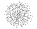
図1に示すように、エンジン(内燃機関)のクランクシャフト(図示せず)と同期回転する駆動側回転部材としての外部ロータ1と、エンジンの燃焼室の吸気弁又は排気弁を開閉するためのカムシャフト3と同軸で一体回転する従動側回転部材としての内部ロータ2と、流体制御弁機構Vとを備えて弁開閉時期制御装置が構成されている。
EMBODIMENT OF THE INVENTION Below, the form for implementing this invention is demonstrated, referring drawings.
(First embodiment)
[Basic configuration]
As shown in FIG. 1, an
この弁開閉時期制御装置は、外部ロータ1(駆動側回転部材)に対して、内部ロータ2(従動側回転部材)を嵌め込んだ構成を有している。これにより外部ロータ1と内部ロータ2とが、回転軸芯Xを中心として所定の相対回転位相の範囲内で相対回転自在となる。外部ロータ1と内部ロータ2との間には流体圧室が形成され、図2に示すように、この流体圧室は、内部ロータ2の外周に支持された仕切りとしてのベーン5によって遅角室11と進角室12とに仕切られている。
ベーン5は内部ロータ2の外周に形成されたベーン溝に挿入され、板バネなどにより突出方向に付勢されている。これにより、外部ロータ1と内部ロータ2との相対位相に関わらず、ベーン5の外端は常に流体圧室内で外部ロータの内面に摺接保持される。
This valve opening / closing timing control device has a configuration in which an internal rotor 2 (driven side rotating member) is fitted into an external rotor 1 (driving side rotating member). As a result, the
The
回転軸芯Xと同軸芯に前述したカムシャフト3が配置され、このカムシャフト3は、連結ボルト4によって内部ロータ2に連結されている。外部ロータ1の一方の面にフロントプレート6が配置され、この外部ロータ1の他方の面にリヤプレート7が配置され、これらは複数の固定ボルト8によって外部ロータ1に固定されている。内部ロータ2はフロントプレート6とリヤプレート7の間に配置されている。
The above-described
リヤプレート7の外周には、タイミングスプロケット7Sが一体的に形成されている。このタイミングスプロケット7Sとエンジンのクランクシャフトに取り付けられたギアとの間にはタイミングチェーンやタイミングベルト等の動力伝達部材(図示せず)が架設される。
A
この構成から、エンジンの稼働時にはクランクシャフトの回転駆動力が動力伝達部材を介してタイミングスプロケット7Sに伝達され、外部ロータ1が図2等に示す回転方向Tに回転駆動する。この回転と連係して内部ロータ2が回転方向Tと同方向に回転することによりカムシャフト3が回転し、カムシャフト3に設けられたカム(図示せず)の駆動回転によりエンジンの吸気弁又は排気弁の開閉作動が行われる。
With this configuration, when the engine is in operation, the rotational driving force of the crankshaft is transmitted to the
エンジンの稼働時に、進角室12に作動油が供給されるとベーン5に作用する圧力で進角室12の容積が拡大するので、外部ロータ1に対して内部ロータ2が矢印T1に移動する。これにより外部ロータ1と内部ロータ2との相対回転位相が進角方向に移動する。
これとは逆に、遅角室11に作動油が供給されるとベーン5に逆向きに作用する圧力で遅角室11の容積が拡大するので、外部ロータ1に対して内部ロータ2が矢印T2に移動する。これにより外部ロータ1と内部ロータ2との相対回転位相が遅角方向に移動する。このようにクランク軸の回転位相に対するカムシャフト3の回転位相を変化させて吸気弁又は排気弁の開閉時期の制御が実現される。
When hydraulic oil is supplied to the
On the contrary, when the hydraulic oil is supplied to the retarding
作動油としてはエンジンオイルが利用され、弁開閉時期制御装置には、外部ロータ1と内部ロータ2との間の相対的な回転位相をエンジンの始動に適した始動最適位相(中間位相とも呼ばれ、所定位相の一例)に保持する保持機構Mが設けられている。この保持機構Mはエンジンの始動直後の作動油の圧力が非常に低い状況において外部ロータ1と内部ロータ2とを設定された相対回転位相に保持することで、クランクシャフトの回転位相に対するカムシャフト3の回転位相を始動最適位相に保持し、エンジンの安定的な始動を現出する。
Engine oil is used as the hydraulic oil, and the valve timing control apparatus determines the relative rotational phase between the
従来の弁開閉時期制御装置における一般的な保持機構は、内部ロータに形成されたロック溝と、このロック溝に対して出退自在となるように外部ロータに支持されたロックピンなどで構成されている。
しかし、本発明による保持機構Mは、外部ロータ1(駆動側回転部材)と、内部ロータ2(従動側回転部材)との間に互いに逆向きの付勢力を作用させる2つのゼンマイバネS1,S2(渦巻きバネ)によって構成されている。第1のゼンマイバネS1は相対位相を進角側に付勢し、第2のゼンマイバネS2は相対位相を遅角側に付勢する。2つのゼンマイバネS1,S2はフロントプレート6に設けられた凹部6aに収納され、ゼンマイバネS1,S2の間には円板状のスペーサ15が介装されている。凹部6aは円板状のカバー9によって覆われている。ゼンマイバネS1,S2の働きの詳細については後述する。
A general holding mechanism in a conventional valve opening / closing timing control device includes a lock groove formed in an internal rotor, and a lock pin supported by an external rotor so as to be able to move in and out of the lock groove. ing.
However, the holding mechanism M according to the present invention has two mainspring springs S1 and S2 (which apply urging forces in opposite directions to each other between the outer rotor 1 (driving side rotating member) and the inner rotor 2 (driven side rotating member). A spiral spring). The first spring S1 biases the relative phase toward the advance side, and the second spring S2 biases the relative phase toward the retard side. The two springs S1, S2 are accommodated in a
図1及び図2に示すように、内部ロータ2には、複数の遅角室11に対する作動油の給排を行う遅角室側油路11aと、複数の進角室12に対する作動の給排を行う進角室側油路12aとが貫通形成されている。保持機構としてロックピンを設けていないので、ロック溝から同ロックピンを押出すためのロック解除用油路なども形成されていない。
As shown in FIGS. 1 and 2, the
図1及び図2に示すように、カムシャフト3に対して相対回転自在に外嵌するブッシュ18を備え、このブッシュ18の供給油路18aからカムシャフト3の内部油路3aと、内部ロータ2の内部油路2aとに順次作動油を供給する油路系が形成されている。この油路系により供給油路18aに対して油圧ポンプPから供給される作動油を内部ロータ2の円筒状空間2Sに供給する。
また、円筒状空間2Sに供給された作動油は、外部ロータ1及び内部ロータ2に対して相対回転自在に支持された流体制御弁機構Vを介して、前述した遅角室側油路11aや進角室側油路12aに供給され、また、遅角室側油路11aと進角室側油路12aとから排出される。
As shown in FIGS. 1 and 2, a
In addition, the hydraulic oil supplied to the
〔流体制御弁機構〕
流体制御弁機構Vは、図1に示すように、スプールバルブ22を有した作動油制御部Vaと、作動油の給排を行うように円柱状の作動油給排部Vbとを一体的に備えたハウジング28を有している。スプールバルブ22は、作動油制御部Vaの上端に配置された電磁ソレノイド21によって図の上下に摺動操作される。作動油給排部Vbは内部ロータ2の円筒状空間2Sに回転自在に挿入されている。
[Fluid control valve mechanism]
As shown in FIG. 1, the fluid control valve mechanism V integrally includes a hydraulic oil control unit Va having a
作動油給排部Vbの中心には、前述した内部油路2aからの作動油を受け入れる主油路23が貫通形成され、その内部には円筒状空間2Sに向かう流体の流れを阻止するチェック弁Cが備えられている。スプールバルブ22は有底の円筒形状を有する。
ハウジング28はエンジンのフロントカバー等に固定されており、内部ロータ2は作動油給排部Vbを介して回転自在に支持されている。
A
The
作動油給排部Vbの外周には、スプールバルブ22によって作動油の給排が制御される2つのポート24、25が環状の溝として形成されている。作動油給排部Vbの外周には第1ポート24、第2ポート25の作動油の漏出を抑制するオイルシール27が外嵌設置されている。第1ポート24は遅角室連通孔11aと常時連通し、第2ポート25は進角室連通孔12aと常時連通している。
On the outer periphery of the hydraulic oil supply / discharge portion Vb, two
スプールバルブ22とハウジング28の底面との間にはスプールバルブ22を図の上向きに付勢する圧縮スプリング29が設置されている。図1の状態でソレノイド21に通電すると、ソレノイド21から下方に突出した操作ロッド30が、スプールバルブ22を下方位置に移動させる。通電を停止すると、操作ロッド30はソレノイド21の側に引退し、スプールバルブ22は圧縮スプリング29の付勢力によりロッド22の動きに追従して図1に示す上方位置に復帰する。
A
スプールバルブ22の外周面には、いずれも環状の排出溝22a、22bと供給溝22cが形成されている。排出溝22a、22bには、内部の中空部に貫通する貫通孔23a、23bが夫々設けられている。
排出溝22a、22b及び供給溝22cの位置関係は、ソレノイド21の非通電時には、図1に示すように、供給溝22cが主油路23及び進角室連通孔12aと連通し、且つ、排出溝22bが遅角側流路11aと連通するよう設定されている。そして、ソレノイド21の通電時には、供給溝22cが主油路23及び遅角側流路11aと連通し、且つ、排出溝22aが進角側流路12aと連通するよう設定してある。
On the outer peripheral surface of the
As shown in FIG. 1, when the
この弁開閉時期制御装置では、内部ロータ2とフロントプレート6との間、及び、内部ロータ2とリヤプレート7との間に作動油が僅かにリークする程度の隙間が形成されており、この他の可動部分を介しても作動油が僅かにリークする。そして、リークした作動油はオイルパン36で回収される。
In this valve opening / closing timing control device, gaps are formed between the
(弁開閉時期制御装置の動作)
図1に示すごとく、相対回転位相を進角方向T1へ変位させる場合には、油圧ポンプPの駆動中にソレノイド21を非通電状態にする。すると、スプールバルブ22は、圧縮スプリング29の付勢力によりソレノイド21のロッド30と共に、ソレノイド21寄りの上方位置に配置される。流体ポンプPからカムシャフト8の主油路23に供給された作動油は、図1に示すように、円筒状空間2S、主油路23、供給溝22c、進角側流路12a、第2ポート25を経て、各進角室12へと圧送される。この圧送によってベーン5が進角方向T1に移動して、各遅角室11の作動油は排出される。遅角室11から排出された作動油は、第1ポート24、遅角側流路11a、排出溝22b、ドレン流路32を介してオイルパン36に排出される。
(Operation of valve timing control device)
As shown in FIG. 1, when the relative rotational phase is displaced in the advance direction T1, the
一方、相対回転位相を遅角方向T2へ変位させる場合には、油圧ポンプPの駆動中にソレノイド21への通電を行う。すると、スプールバルブ22は、ソレノイド21のロッド22に押されて、下方位置に配置される。流体ポンプPからカムシャフト8の主油路23に供給された作動油は、円筒状空間2S、主油路23、供給溝22c、遅角側流路11a、第1ポート24を経て、各遅角室11へと圧送される。この圧送によってベーン5が遅角方向T2に移動して、各進角室12の作動油は排出される。進角室12から排出された作動油は、第2ポート25、進角側流路12a、排出溝22a、ドレン流路32を介してオイルパン36に排出される。
On the other hand, when the relative rotational phase is displaced in the retard direction T2, the
〔制御系の概要〕
図面には示していないが、弁開閉時期制御装置の制御系は、エンジンのクランクシャフトの回転角を検出するクランク角センサと、カムシャフト3の回転角を検出するカムシャフト角センサと、流体制御弁機構Vを制御するECU(図示せず)とを備えている。
ECUには、イグニッションキーのON/OFF情報、エンジンオイルの油温を検出する油温センサからの情報等を取得する信号系が形成されており、不揮発性メモリ内にエンジンの運転状態に応じた最適の相対回転位相の制御情報を記憶している。
[Outline of control system]
Although not shown in the drawings, the control system of the valve timing control device includes a crank angle sensor that detects the rotation angle of the crankshaft of the engine, a camshaft angle sensor that detects the rotation angle of the
The ECU is formed with a signal system for acquiring information such as ignition key ON / OFF information, information from an oil temperature sensor that detects the oil temperature of the engine oil, and the like in the nonvolatile memory according to the operating state of the engine. The control information of the optimal relative rotational phase is stored.
そして、ECUは、前述したクランク角センサとカムシャフト角センサとの検出結果から外部ロータ1と内部ロータ2との相対位相を検出する。そして、この相対位相の情報と運転状態(エンジン回転数、冷却水温など)の情報とに基づいて、流体制御弁機構Vを操作することで遅角室11と進角室12とに対する作動油の給排を行い、外部ロータ1と内部ロータ2との相対回転位相を制御する。これにより、最遅角位相(遅角室11の容積が最大となる相対回転位相)と最進角位相(進角室12の容積が最大となる相対回転位相)との間で位相制御を実現する。
Then, the ECU detects the relative phase between the
エンジンを停止させる操作が行われると、ECUが流体制御弁機構Vによって遅角室11及び進角室12に対する作動油の給排は停止され、ベーン5に対していずれの向きの作動油圧も作用しない状態になり、これにより、外部ロータ1と内部ロータ2との相対位相は、前述したゼンマイバネS1,S2の付勢作用により、次回の始動に適した始動最適位相に変位された状態でエンジンが停止する。そして、この停止の後にエンジンを始動させた際には、安定的にエンジンが始動する。
When the operation for stopping the engine is performed, the ECU stops the supply and discharge of the hydraulic oil to and from the
尚、前述したゼンマイバネS1,S2は互いに協働して、外部ロータ1に対して内部ロータ2が始動最適位相より遅角側の領域にある場合に、吸気弁や排気弁のバルブスプリングから受ける反力と抗うように、内部ロータ2に対して始動最適位相の方向に付勢力を作用させる機能を有している。具体的には、相対位相を進角側に付勢するゼンマイバネS1付勢力を遅角側に付勢するゼンマイバネS2よりも高めに設定してある。従って、カムシャフト3と一体回転する内部ロータ2の相対位相が、吸気弁や排気弁のバルブスプリングから受ける反力のために、外部ロータ1の回転に対し遅れ傾向になる不都合や、遅角室11及び進角室12から作動油が排出された時に、始動最適位相よりも遅角側に保持される傾向が抑制される。
The springs S1 and S2 described above cooperate with each other to react to the
エンジンの始動後には、ECUが流体制御弁機構Vによって遅角室11及び進角室12に対する作動油の給排を行うことで、外部ロータ1と内部ロータ2との相対位相を変更し、ECUによる吸気弁、排気弁の開閉時期の制御が行われる。
過大な負荷がエンジンに作用したためにエンジンストップの状態に陥った場合には、外部ロータ1に対して内部ロータ2が最遅角位相に達していることもある。このような状況でエンジンを始動した場合には、安定的なエンジン始動を行うために、ECUは、外部ロータ1に対する内部ロータの位相を早期に始動最適位相に移動させる制御を行う。
After the engine is started, the ECU changes the relative phase between the
When the engine stops due to an excessive load acting on the engine, the
具体的な制御形態として、ECUの制御により流体制御弁機構Vは、遅角室11の作動油を排出すると共に、進角室12に作動油を供給することで、外部ロータ1に対して内部ロータ2を始動最適位相の方向に移動させる。尚、最遅角位相のうち内部ロータ2が最も遅角側にある回転位相を最遅角位相と称する。
As a specific control form, the fluid control valve mechanism V discharges the hydraulic oil in the
しかしながら、上記の制御によると、内部ロータ2が最遅角位相にある状態においてエンジンを始動した場合に、相対回転位相が始動最適位相に達するまでに時間を要することになり、エンジンの始動が円滑に行われない。特に、寒冷地でのエンジン停止時に低温であることから作動油の粘性が高く、遅角室11、進角室12に対する作動油の給排が円滑に行われず、この理由からもエンジンの始動が円滑に行われない。このような不都合を改善するため、前述したゼンマイバネS1,S2の強弱差が外部ロータ1と内部ロータ2との始動最適位相方向への相対移動をアシストして始動最適位相に達するまでの時間の短縮を図っている。
However, according to the above control, when the engine is started in a state where the
〔ゼンマイバネ〕
図3〜図8に示すように、第1ゼンマイバネS1は、外部ロータ1に対する内部ロータ2の回転位相を、最遅角位相から始動最適位相までの遅角領域Aにて始動最適位相の方向に付勢する働きをする。逆に、第2ゼンマイバネS2は、外部ロータ1に対する内部ロータ2の回転位相を、最進角位相から始動最適位相までの進角領域Bにて始動最適位相の方向に付勢する働きをする。
図8に示すように、これらのゼンマイバネS1,S2は帯状のバネ材を渦巻き状に成形したもののため、トーションバネのようにコイル部を備えたものと比較すると厚み(回転軸芯X方向での寸法)を小さくでき、図1に示すように2つのゼンマイバネS1,S2を設けた場合でも、回転軸芯Xの方向で大きいスペースを必要とせず、弁開閉時期制御装置の小型化を実現する。
[Spring spring]
As shown in FIGS. 3 to 8, the first main spring S <b> 1 causes the rotational phase of the
As shown in FIG. 8, these springs S1 and S2 are formed by spirally forming a belt-shaped spring material, and therefore have a thickness (in the direction of the rotation axis X) compared to that having a coil portion such as a torsion spring. 1), even when two springs S1 and S2 are provided as shown in FIG. 1, a large space is not required in the direction of the rotation axis X, and the valve opening / closing timing control device can be downsized.
図3に示すように、各ゼンマイバネS1,S2は、渦巻き状のバネ本体30を備え、その内径側の端部には内部ロータ2と係合される内側係合部31が径方向内向きに折曲げ加工により形成され、その外径側の端部には外部ロータ1に固定される外側係合部32が径方向外向きに折曲げ加工により形成されている。
このようなゼンマイバネS1,S2の形状と対応するように、内部ロータ2の軸状部10の外周の一箇所には、内側係合部31を係止可能な係合凹部10Gが形成されている。他方、外部ロータ1に連結されたフロントプレート6の内面の一箇所には、外側係合部32を係止可能な係合凹部6Tが形成されている。
As shown in FIG. 3, each of the springs S <b> 1 and S <b> 2 includes a
An
ゼンマイバネS1,S2をセットする際には、先ず、外側係合部32を外部ロータ1の係合凹部6Tに係止固定した後、直線状に復帰しようとするゼンマイバネS1,S2の付勢力に抗うように、言い換えれば内側係合部31をバネ本体30が軸心X回りで内径方向に巻き込まれる方向に所定回数だけ回転させた上で、内側係合部31を係合凹部10Gに係止固定する。上記セットを実施する際における内側係合部31の回転操作方向は、図2において第1ゼンマイバネS1では反時計回り、第2ゼンマイバネS2では時計回りとなる。
When setting the springs S1 and S2, first, the outer engaging
以上の要領でセットすることにより、ゼンマイバネS1,S2の両端が外部ロータ1と内部ロータ2とにそれぞれ確実に相対移動不能に固定されると共に、第1ゼンマイバネS1の内側係合部31が内部ロータ2を進角側(図2の時計方向)に付勢し、第2ゼンマイバネS2の内側係合部31が内部ロータ2を遅角側(図2の反時計方向)に付勢する構成が実現される。
尚、2つのゼンマイバネS1,S2のいずれか一方のみをフロントプレート6に設けられた凹部6aに配置し、他方をリヤプレート7に形成した凹部に配置してもよく、この場合は円板状のスペーサ15が不要となる。
By setting in the above manner, both ends of the springs S1, S2 are securely fixed to the
Only one of the two springs S1, S2 may be disposed in the
〔運転制御〕
前述したように、通常のエンジン始動時には、遅角室11及び進角室12に対する作動油の給排は停止されているので、図2及び図3に示すように、ゼンマイバネS1,S2の付勢作用により、外部ロータ1と内部ロータ2との相対位相は最遅角位相と最進角位相の間にある始動最適位相に保持されている。したがって、安定的にエンジンを始動できる。イグニッションキーのON操作によりエンジンの始動が指令されると、セルモータによるクランキングが実施され、エンジンが始動し、油圧ポンプPが回転し、遅角室11及び進角室12への作動油の供給が可能となる。
(Operation control)
As described above, when the engine is started normally, the supply and discharge of the hydraulic oil to and from the
エンジンの始動後は一般に、ECUの制御により流体制御弁機構Vによって遅角室11に作動油を供給することで、相対回転位相を始動最適位相よりも少し遅角位相側の中間規制位相に変位させる。中間規制位相はエミッションの改善や、低温時のトルクアップに適した位相であり、一般に暖気運転中は同位相に保持させる。尚、図4及び図5は、中間規制位相を超えた最遅角位相の状態を示す。
In general, after the engine is started, hydraulic fluid is supplied to the
遅角室11への作動油の供給による始動最適位相から中間規制位相など遅角位相側への変位操作は、図4及び図5における内部ロータ2の反時計方向の相対回転操作を伴うので、第1ゼンマイバネS1の付勢力に抗して、すなわち第1ゼンマイバネS1の更なる引き絞りを伴って行われる。他方、第2ゼンマイバネS2は、十分に引き絞られた状態でセットされているので、始動最適位相から遅角位相側への変位に際しては、単に始動最適位相での状態よりも弛められるのみで、実質的に相対回転位相を進角向きに移動させる付勢力を発揮することはない。暖気運転期間を過ぎると、ECUが通常の運転制御に移行させる。
The displacement operation from the optimum starting phase to the retarding phase side such as the intermediate restriction phase by supplying hydraulic oil to the retarding
他方、通常の運転制御において、始動最適位相よりも進角側に変位操作する際には、図6及び図7における内部ロータ2の時計方向の相対回転操作を伴うので、第2ゼンマイバネS2の付勢力に抗して、すなわち第2ゼンマイバネS2の引き絞りを伴って行われる。他方、第1ゼンマイバネS2は、十分に引き絞られた状態でセットされているので、始動最適位相から進角側への変位に際しては、単に始動最適位相での状態よりも弛められるのみで、実質的に相対回転位相を遅角向きに移動させる付勢力を発揮することはない。尚、図6及び図7は最進角位相の状態を示す。
On the other hand, in the normal operation control, when the displacement operation is performed on the advance side from the optimum starting phase, the relative rotation operation of the
(第2実施形態)
以下、本発明の第2の実施の形態を図面に基づいて説明する。
第2実施形態でも、第1実施形態と同様に、外部ロータ1と内部ロータ2との間の相対的な回転位相をエンジンの始動に適した始動最適位相に保持する保持機構Mとして、互いに逆向きの付勢力を発揮付勢する2つのゼンマイバネS1,S2を備えている。
(Second Embodiment)
Hereinafter, a second embodiment of the present invention will be described with reference to the drawings.
In the second embodiment, as in the first embodiment, the holding mechanisms M that hold the relative rotational phase between the
第2実施形態の構成上の第1の特徴は、図9から図12に示すように、内部ロータ2の係合凹部10Gの周方向の幅が、ゼンマイバネS1,S2の内側係合部31の厚みよりも十分大きく形成されている点である。この構成により、係合凹部10Gに係止された各内側係合部31が係合凹部10G内で周方向に沿って移動可能となっている。
As shown in FIGS. 9 to 12, the first feature of the configuration of the second embodiment is that the circumferential width of the
第2実施形態の構成上の第2の特徴は、フロントプレート6に、第1ゼンマイバネS1の内側係合部31に接当可能な第1規制片33Aが立設され、同様に、第2ゼンマイバネS2の内側係合部31に接当可能な第2規制片33Bが立設されている点である。第1規制片33Aは、第1ゼンマイバネS1の内側係合部31の進角領域Bの方向への変位を規制し、第2規制片33Bは、第2ゼンマイバネS2の内側係合部31の遅角領域Aの方向への変位を規制する。
The second structural feature of the second embodiment is that the
その結果、図10(a)に示すように、第1ゼンマイバネS1は、外部ロータ1に対する内部ロータ2の回転位相を、最遅角位相から第1規制片33Aが規定する第1所定位相(始動最適位相に相当)までの遅角領域Aにて始動最適位相の方向に付勢する働きをする。逆に、第2ゼンマイバネS2は、図11(b)に示すように、外部ロータ1に対する内部ロータ2の回転位相を、最進角位相から第1規制片33Bが規定する第2所定位相(始動最適位相に相当)までの進角領域Bにて始動最適位相の方向に付勢する働きをする。
As a result, as shown in FIG. 10A, the first main spring S1 has a first predetermined phase (starting) in which the
図10(b)に示すように、最遅角位相から始動最適位相までの遅角領域Aでは、第2ゼンマイバネS2の内側係合部31は第2規制片33Bによって係止されることで、幅広の係合凹部10G内で進角方向に相対移動して最早内部ロータ2に作用し得ない。そのため、第1ゼンマイバネS1の付勢力のみが回転位相に作用し、第2ゼンマイバネS2からは回転位相に付勢力が作用しない。
As shown in FIG. 10B, in the retarded angle region A from the most retarded phase to the optimum starting phase, the inner engaging
逆に、図11(a)に示すように、最進角位相から始動最適位相までの進角領域Bでは、第1ゼンマイバネS1の内側係合部31は第1規制片33Aによって係止されることで、幅広の係合凹部10G内で遅角方向に相対移動して最早内部ロータ2に作用し得ない。
そのため、第2ゼンマイバネS2の付勢力のみが回転位相に作用し、第1ゼンマイバネS1からは回転位相に付勢力が作用しない。
Conversely, as shown in FIG. 11A, in the advance angle region B from the most advanced angle phase to the optimum starting phase, the
For this reason, only the urging force of the second spring spring S2 acts on the rotational phase, and no urging force acts on the rotational phase from the first spring spring S1.
その結果、各ゼンマイバネS1,S2の内側係合部31による内部ロータ2に対する付勢操作位置が第1、第2規制片33A,33Bの各位置までに限定されるので、遅角室11及び進角室12に対する作動油の給排が停止されると、図9に示すように、各ゼンマイバネS1,S2の付勢力のバランスが長期間の使用などにより当初の状態から崩れた場合でも、回転位相が前記バランスの崩れによってずれることなく始動最適位相に精度よく保持することが可能となる。
As a result, the urging operation positions of the main springs S1, S2 with respect to the
( 第3実施形態)
第3実施形態は図13及び図14に例示するように、相対位相を始動最適位相に保持する付勢部材として、ゼンマイバネではなく2本のトーションバネS1,S2を用いた形態といえる。ここでは、相対位相を進角側に付勢する第1トーションバネS1はフロントプレート6の凹部6aに収納されているのに対して、遅角側に付勢する第2トーションバネS2はリヤプレート7の凹部7aに収納されている。
(Third embodiment)
As illustrated in FIGS. 13 and 14, the third embodiment can be said to use two torsion springs S <b> 1 and S <b> 2 instead of the mainspring as an urging member that maintains the relative phase at the optimum starting phase. Here, the first torsion spring S1 that biases the relative phase toward the advance side is housed in the
図14は始動最適位相における各トーションバネS1,S2の状態を示す。
トーションバネS1,S2の外側端部32は外部ロータ1に連結されたフロントプレート6の内面の係合凹部6Tに相対移動不能に係止されている。しかし、トーションバネS1,S2の内側端部31は、内側端部31の外径よりも十分に長く切り取られた幅広の係合凹部10Gに相対移動可能に係止されている。
そして、フロントプレート6の底部からは、トーションバネS1,S2の内側端部31と係合可能な規制片33A,33Bが立設されている。
幅広の係合凹部10Gと規制片33A,33Bとによって、第2実施形態と同様に以下の作用効果が奏される。
FIG. 14 shows the states of the torsion springs S1 and S2 in the optimum starting phase.
The
And from the bottom part of the
The following effects are achieved by the wide
図14(a)から理解されるように、最進角位相から始動最適位相までの進角領域Bでは、第1トーションバネS1の内側係合部31は第1規制片33Aによって係止されるため内部ロータ2に作用しない。そのため、第2トーションバネS2の付勢力のみが回転位相に作用し、第1トーションバネS1からは回転位相に付勢力が作用しない。
逆に、図14(b)から理解されるように、最遅角位相から始動最適位相までの遅角領域Aでは、第2トーションバネS2の内側係合部31は第2規制片33Bによって係止されるため内部ロータ2に作用しない。そのため、第1ゼンマイバネS1の付勢力のみが回転位相に作用し、第2トーションバネS2からは回転位相に付勢力が作用しない。
As understood from FIG. 14A, in the advance angle region B from the most advanced angle phase to the optimum starting phase, the
On the contrary, as understood from FIG. 14B, in the retardation region A from the most retarded phase to the optimum starting phase, the
その結果、各トーションバネS1,S2の内側係合部31による内部ロータ2に対する付勢操作位置が第1、第2規制片33A,33Bの各位置までに限定されるので、遅角室11及び進角室12に対する作動油の給排が停止されると、各トーションバネS1,S2の付勢力のバランスが長期間の使用などにより当初の状態から崩れた場合でも、回転位相が前記バランスの崩れによってずれることなく始動最適位相に精度よく保持することが可能となる。第1規制片33Aの位置は第1所定位相に相当し、第2規制片33Bの位置は第2所定位相に相当する。
As a result, the biasing operation positions of the
( 第4実施形態)
第4実施形態は、図15に示すように、相対位相を始動最適位相に保持する付勢部材として、内部ロータ2の係合凹部10Gに係止された内側係合部31と、外部ロータ1の係合凹部6Tに係止された外側係合部32とを有する1本のトーションバネSを用いている。
この形態では、遅角室11及び進角室12に対する作動油の給排が停止されると、トーションバネSの付勢力によって相対位相が始動最適位相に変位操作され、同位相に保持される。作動油による始動最適位相から遅角側への変位操作は、図15の上方から見たとき、トーションバネSの内側係合部31が外側係合部32に対して反時計方向に相対回転されるように、従って、トーションバネSが縮径する変形を伴って行われる。逆に、始動最適位相から進角側への変位操作は、図15の上方から見たとき、トーションバネSの内側係合部31が外側係合部32に対して時計方向に相対回転されるように、従って、トーションバネSが拡径する変形を伴って行われる。
(Fourth embodiment)
In the fourth embodiment, as shown in FIG. 15, as an urging member that keeps the relative phase at the optimum starting phase, the
In this embodiment, when the supply and discharge of the hydraulic oil to and from the
( 第5実施形態)
第5実施形態は、内部ロータ2の係合凹部10が周方向に非常に長く形成されており、相対位相を始動最適位相に保持する付勢部材として、円柱状の作動油給排部Vbに外嵌された1本のトーションバネSを用いている。このトーションバネSの両端31a,31bはいずれも径方向外向きに延出されており、両端31a,31bどうしをトーションバネSの付勢力に抗して近接させた状態で係合凹部10に係入させている。
フロントプレート6には、両端31a,31bの付近にトーションバネSの外側に接当または隣接する一対の規制片34A、34Bが立設されている。遅角室11及び進角室12に対する作動油の給排が停止された状態では、図16(a)に示すように、トーションバネSの両端31a,31bが係合凹部10の両端10a,10bと一対の規制片34A、34Bとに同時に押付けられることで、相対位相を始動最適位相に付勢している。
作動油の作用によって相対位相が遅角側に変位操作されると、図16(b)に例示するように、トーションバネSの一端31bは規制片34Bに押付けられたまま、内部ロータ2の係合凹部10Gの一方の端面10aがトーションバネSの他端31aを反時計方向に押し操作しながら変位操作が実行される。
(Fifth embodiment)
In the fifth embodiment, the engagement
The
When the relative phase is displaced to the retard side by the action of the hydraulic oil, as shown in FIG. 16B, the
本発明は、エンジンの吸気弁と排気弁との少なくとも一方の開閉タイミングを設定する弁開閉時期制御装置全般に利用することができる。 The present invention can be used for all valve opening / closing timing control devices for setting the opening / closing timing of at least one of an intake valve and an exhaust valve of an engine.
1 外部ロータ(駆動側回転部材)
2 内部ロータ(従動側回転部材)
2S 円筒状空間
3 カムシャフト
5 ベーン(仕切り)
6 フロントプレート
6T 係合凹部
7 リヤプレート
10 軸状体
10G 係合凹部
11 遅角室
11a 遅角室側油路
12 進角室
12a 進角室側油路
22 スプールバルブ
24 第1ポート
25 第2ポート
28 ハウジング
33A 第1規制片
33B 第2規制片
M 保持機構
P 油圧ポンプ
S1 第1ゼンマイバネ(スプリング)
S2 第2ゼンマイバネ(スプリング)
T1 進角方向
T2 遅角方向
V 流体制御弁機構
Va 作動油制御部
Vb 作動油給排部
1 External rotor (drive side rotating member)
2 Internal rotor (driven side rotating member)
6
S2 Second spring (spring)
T1 Advance angle direction T2 Delay angle direction V Fluid control valve mechanism Va Hydraulic oil control part Vb Hydraulic oil supply / discharge part
Claims (4)
前記駆動側回転部材に対して同軸上に配置され、前記内燃機関の吸気弁及び排気弁の少なくとも一方を開閉するカムシャフトに対して一体回転する従動側回転部材と、
前記駆動側回転部材と前記従動側回転部材の間の相対位相を、可動する仕切りによって容積が相補に可変する2種類の圧力室のそれぞれに対する作動流体の給排によって進角位相側または遅角位相側に変位させる位相変換機構と、
前記相対位相を最進角位相及び最遅角位相を除く前記内燃機関の始動に適した所定位相に向けて付勢する付勢部材と、を有し、
前記付勢部材は、前記相対位相を進角位相方向へ付勢する第1付勢部材と前記相対位相を遅角位相方向へ付勢する第2付勢部材とを有し、さらに、
前記第1付勢部材による付勢力を前記所定位相と最遅角位相の間に限定する第1規制部と、前記第2付勢部材による付勢力を前記所定位相と最進角位相の間に限定する第2規制部とを備えている弁開閉時期制御装置。 A drive-side rotating member that rotates synchronously with the crankshaft of the internal combustion engine;
A driven-side rotating member that is coaxially disposed with respect to the driving-side rotating member and rotates integrally with a camshaft that opens and closes at least one of an intake valve and an exhaust valve of the internal combustion engine;
The relative phase between the driving side rotating member and the driven side rotating member is set to an advance phase phase or a retard angle phase depending on supply / discharge of working fluid to / from each of the two types of pressure chambers whose volumes are complementarily variable by a movable partition. A phase conversion mechanism to be displaced to the side,
Have a, a biasing member for biasing the relative phase to a predetermined phase suitable for startup of the internal combustion engine except for a most advanced angle phase and the most retarded angle phase,
The urging member includes a first urging member that urges the relative phase in the advance angle phase direction and a second urging member that urges the relative phase in the retard angle phase direction, and
A first restricting portion that limits an urging force by the first urging member between the predetermined phase and the most retarded phase; and an urging force by the second urging member between the predetermined phase and the most advanced angle phase. The valve timing control apparatus provided with the 2nd control part to limit .
前記駆動側回転部材に対して同軸上に配置され、前記内燃機関の吸気弁及び排気弁の少なくとも一方を開閉するカムシャフトに対して一体回転する従動側回転部材と、
前記駆動側回転部材と前記従動側回転部材とにより形成され、容積が拡大することにより前記駆動側回転部材に対する前記従動側回転部材の相対位相を遅角方向に移動させる遅角室、及び、容積が拡大することにより前記相対位相を進角方向に移動させる進角室と、
前記相対位相を最進角位相及び最遅角位相を除く所定位相に向けて付勢する付勢部材と、を有し、
前記付勢部材は、前記相対位相を最遅角位相よりも進角位相方向側に位置する第1所定位相へ付勢する第1付勢部材と前記相対位相を最進角位相よりも遅角位相方向側に位置する第2所定位相へ付勢する第2付勢部材とを有し、
前記第1付勢部材は、前記相対位相を最遅角位相から前記第1所定位相まで付勢すると共に前記第1所定位相から最進角位相までは付勢せず、
前記第2付勢部材は、前記相対位相を最進角位相から前記第2所定位相まで付勢すると共に前記第2所定位相から最遅角位相までは付勢しない弁開閉時期制御装置。 A drive-side rotating member that rotates synchronously with the crankshaft of the internal combustion engine;
A driven-side rotating member that is coaxially disposed with respect to the driving-side rotating member and rotates integrally with a camshaft that opens and closes at least one of an intake valve and an exhaust valve of the internal combustion engine;
A retarding chamber formed by the drive-side rotating member and the driven-side rotating member, and moving the relative phase of the driven-side rotating member with respect to the driving-side rotating member in the retarding direction by increasing the volume, and a volume An advance chamber that moves the relative phase in the advance direction by expanding
Have a, a biasing member for biasing the relative phase to a predetermined phase except for a most advanced angle phase and the most retarded angle phase,
The urging member includes a first urging member that urges the relative phase to a first predetermined phase that is positioned on the advance phase direction side of the most retarded phase, and the relative phase that is retarded from the most advanced angle phase. A second biasing member that biases to a second predetermined phase located on the phase direction side,
The first biasing member biases the relative phase from the most retarded phase to the first predetermined phase and does not bias from the first predetermined phase to the most advanced angle phase.
The valve bias timing control device, wherein the second biasing member biases the relative phase from the most advanced angle phase to the second predetermined phase and does not bias from the second predetermined phase to the most retarded phase .
Priority Applications (4)
| Application Number | Priority Date | Filing Date | Title |
|---|---|---|---|
| JP2009220652A JP5382440B2 (en) | 2009-09-25 | 2009-09-25 | Valve timing control device |
| EP10002953A EP2302177B1 (en) | 2009-09-25 | 2010-03-19 | Valve opening/closing timing control device |
| US12/748,518 US20110073055A1 (en) | 2009-09-25 | 2010-03-29 | Valve opening/closing timing control device |
| CN2010101476197A CN102032009A (en) | 2009-09-25 | 2010-03-31 | Valve opening/closing timing control device |
Applications Claiming Priority (1)
| Application Number | Priority Date | Filing Date | Title |
|---|---|---|---|
| JP2009220652A JP5382440B2 (en) | 2009-09-25 | 2009-09-25 | Valve timing control device |
Publications (2)
| Publication Number | Publication Date |
|---|---|
| JP2011069287A JP2011069287A (en) | 2011-04-07 |
| JP5382440B2 true JP5382440B2 (en) | 2014-01-08 |
Family
ID=43333228
Family Applications (1)
| Application Number | Title | Priority Date | Filing Date |
|---|---|---|---|
| JP2009220652A Expired - Fee Related JP5382440B2 (en) | 2009-09-25 | 2009-09-25 | Valve timing control device |
Country Status (4)
| Country | Link |
|---|---|
| US (1) | US20110073055A1 (en) |
| EP (1) | EP2302177B1 (en) |
| JP (1) | JP5382440B2 (en) |
| CN (1) | CN102032009A (en) |
Families Citing this family (17)
| Publication number | Priority date | Publication date | Assignee | Title |
|---|---|---|---|---|
| WO2012094324A1 (en) | 2011-01-04 | 2012-07-12 | Hilite Germany Gmbh | Valve timing control apparatus and method |
| JP5739168B2 (en) * | 2011-01-12 | 2015-06-24 | 日立オートモティブシステムズ株式会社 | Valve timing control device for internal combustion engine |
| JP5447436B2 (en) * | 2011-05-20 | 2014-03-19 | 株式会社デンソー | Valve timing adjustment device |
| JP5382086B2 (en) * | 2011-10-25 | 2014-01-08 | 株式会社デンソー | Hydraulic valve timing adjustment device |
| DE102012200683B4 (en) * | 2012-01-18 | 2017-01-26 | Schaeffler Technologies AG & Co. KG | Phaser |
| JP5928158B2 (en) * | 2012-05-25 | 2016-06-01 | アイシン精機株式会社 | Valve timing control device |
| US8973542B2 (en) | 2012-09-21 | 2015-03-10 | Hilite Germany Gmbh | Centering slot for internal combustion engine |
| JP5661725B2 (en) * | 2012-12-13 | 2015-01-28 | サンコール株式会社 | Mainspring |
| US9366161B2 (en) | 2013-02-14 | 2016-06-14 | Hilite Germany Gmbh | Hydraulic valve for an internal combustion engine |
| DE102014216119A1 (en) * | 2013-08-22 | 2015-02-26 | Schaeffler Technologies Gmbh & Co. Kg | Method and device for winding a return spring with a two-part rotor for a cam phaser |
| CN106103919B (en) * | 2014-03-25 | 2019-04-30 | Ntn株式会社 | Sealing ring |
| US9784143B2 (en) | 2014-07-10 | 2017-10-10 | Hilite Germany Gmbh | Mid lock directional supply and cam torsional recirculation |
| DE102015217261B3 (en) | 2015-09-10 | 2016-12-15 | Schaeffler Technologies AG & Co. KG | Camshaft adjuster with a spring |
| CN108603422B (en) * | 2016-03-15 | 2020-07-28 | 日立汽车系统株式会社 | Valve timing control device for internal combustion engine and method of mounting the valve timing control device |
| DE102017110599A1 (en) * | 2017-05-16 | 2018-11-22 | Schaeffler Technologies AG & Co. KG | Housing for a camshaft adjusting device |
| DE112019007307T5 (en) * | 2019-07-09 | 2022-01-27 | Mikuni Corporation | VALVE TIMING SWITCH |
| US10883396B1 (en) * | 2019-08-21 | 2021-01-05 | Schaeffler Technologies AG & Co. KG | Camshaft phaser with resilient cover plate |
Family Cites Families (18)
| Publication number | Priority date | Publication date | Assignee | Title |
|---|---|---|---|---|
| JP3733730B2 (en) * | 1998-01-30 | 2006-01-11 | トヨタ自動車株式会社 | Valve timing control device for internal combustion engine |
| JP4158185B2 (en) * | 1999-12-15 | 2008-10-01 | 株式会社デンソー | Valve timing adjustment device |
| US6439184B1 (en) * | 2001-01-31 | 2002-08-27 | Denso Corporation | Valve timing adjusting system of internal combustion engine |
| JP2002295275A (en) * | 2001-03-29 | 2002-10-09 | Denso Corp | Valve timing adjustment device |
| JP4487449B2 (en) * | 2001-06-28 | 2010-06-23 | アイシン精機株式会社 | Valve timing control device |
| JP4032288B2 (en) * | 2002-03-28 | 2008-01-16 | アイシン精機株式会社 | Valve timing control device |
| US7556000B2 (en) * | 2002-05-21 | 2009-07-07 | Delphi Technologies, Inc. | Camshaft phaser having designated contact vane |
| US7311069B2 (en) * | 2003-06-25 | 2007-12-25 | Aisin Seiki Kabushiki Kaisha | Variable valve timing control device |
| JP2005016482A (en) * | 2003-06-27 | 2005-01-20 | Aisin Seiki Co Ltd | Valve timing controlling device |
| DE102006004760A1 (en) * | 2006-02-02 | 2007-10-11 | Schaeffler Kg | Hydraulic camshaft adjuster |
| GB2437305B (en) | 2006-04-19 | 2011-01-12 | Mechadyne Plc | Hydraulic camshaft phaser with mechanical lock |
| US7614370B2 (en) * | 2006-06-06 | 2009-11-10 | Delphi Technologies, Inc. | Vane-type cam phaser having bias spring system to assist intermediate position pin locking |
| JP4238903B2 (en) * | 2006-09-13 | 2009-03-18 | 株式会社日立製作所 | Camshaft phase varying device and phase varying device for internal combustion engine |
| JP2009074414A (en) * | 2007-09-20 | 2009-04-09 | Hitachi Ltd | Variable valve gear system and variable valve device for internal combustion engine |
| DE102009005114A1 (en) * | 2008-01-30 | 2009-08-06 | Schaeffler Kg | Camshaft adjusting device |
| US20090211549A1 (en) * | 2008-02-21 | 2009-08-27 | Schaeffler Kg | Cam phase adjuster with a plurality of springs |
| US8127728B2 (en) | 2008-03-21 | 2012-03-06 | Delphi Technologies, Inc. | Vane-type cam phaser having dual rotor bias springs |
| JP5403341B2 (en) * | 2009-06-17 | 2014-01-29 | アイシン精機株式会社 | Valve timing control device |
-
2009
- 2009-09-25 JP JP2009220652A patent/JP5382440B2/en not_active Expired - Fee Related
-
2010
- 2010-03-19 EP EP10002953A patent/EP2302177B1/en not_active Not-in-force
- 2010-03-29 US US12/748,518 patent/US20110073055A1/en not_active Abandoned
- 2010-03-31 CN CN2010101476197A patent/CN102032009A/en active Pending
Also Published As
| Publication number | Publication date |
|---|---|
| CN102032009A (en) | 2011-04-27 |
| EP2302177B1 (en) | 2012-10-31 |
| JP2011069287A (en) | 2011-04-07 |
| EP2302177A1 (en) | 2011-03-30 |
| US20110073055A1 (en) | 2011-03-31 |
Similar Documents
| Publication | Publication Date | Title |
|---|---|---|
| JP5382440B2 (en) | Valve timing control device | |
| JP5516937B2 (en) | Valve timing control device | |
| JP5582363B2 (en) | Valve timing control device | |
| JP5403341B2 (en) | Valve timing control device | |
| JP5516938B2 (en) | Valve timing control device | |
| JP5500350B2 (en) | Valve timing control device | |
| JP5376227B2 (en) | Valve timing control device | |
| JP5321911B2 (en) | Valve timing control device | |
| KR20010012925A (en) | Valve timing control device of internal combustion engine | |
| EP2881620B1 (en) | Variable Valve Timing Control Apparatus | |
| JP4498976B2 (en) | Valve timing control device for internal combustion engine | |
| JP6225725B2 (en) | Valve timing control device | |
| JP5370419B2 (en) | Valve timing adjustment device | |
| JP3817067B2 (en) | Valve timing control device for internal combustion engine | |
| EP2891773B1 (en) | Variable valve timing control apparatus | |
| JP6171423B2 (en) | Valve timing control device | |
| JP3817065B2 (en) | Valve timing control device for internal combustion engine | |
| JP6229538B2 (en) | Solenoid valve | |
| JP6102188B2 (en) | Valve timing control device | |
| CN113167141B (en) | Valve timing control device for internal combustion engine | |
| JP5022327B2 (en) | Variable valve timing mechanism for internal combustion engine | |
| WO2020084764A1 (en) | Valve timing adjustment device | |
| JP6131665B2 (en) | Valve timing control device | |
| JP5574205B2 (en) | Valve timing control device | |
| JP2014020223A (en) | Valve opening/closing timing control device |
Legal Events
| Date | Code | Title | Description |
|---|---|---|---|
| A621 | Written request for application examination |
Free format text: JAPANESE INTERMEDIATE CODE: A621 Effective date: 20120822 |
|
| A977 | Report on retrieval |
Free format text: JAPANESE INTERMEDIATE CODE: A971007 Effective date: 20130627 |
|
| A131 | Notification of reasons for refusal |
Free format text: JAPANESE INTERMEDIATE CODE: A131 Effective date: 20130704 |
|
| A521 | Written amendment |
Free format text: JAPANESE INTERMEDIATE CODE: A523 Effective date: 20130812 |
|
| TRDD | Decision of grant or rejection written | ||
| A01 | Written decision to grant a patent or to grant a registration (utility model) |
Free format text: JAPANESE INTERMEDIATE CODE: A01 Effective date: 20130905 |
|
| A61 | First payment of annual fees (during grant procedure) |
Free format text: JAPANESE INTERMEDIATE CODE: A61 Effective date: 20130918 |
|
| R151 | Written notification of patent or utility model registration |
Ref document number: 5382440 Country of ref document: JP Free format text: JAPANESE INTERMEDIATE CODE: R151 |
|
| LAPS | Cancellation because of no payment of annual fees |