JP5380070B2 - Head unit with adjustable conduit and hood used for the head unit - Google Patents
Head unit with adjustable conduit and hood used for the head unit Download PDFInfo
- Publication number
- JP5380070B2 JP5380070B2 JP2008521609A JP2008521609A JP5380070B2 JP 5380070 B2 JP5380070 B2 JP 5380070B2 JP 2008521609 A JP2008521609 A JP 2008521609A JP 2008521609 A JP2008521609 A JP 2008521609A JP 5380070 B2 JP5380070 B2 JP 5380070B2
- Authority
- JP
- Japan
- Prior art keywords
- shell
- headband
- head unit
- hood
- head
- Prior art date
- Legal status (The legal status is an assumption and is not a legal conclusion. Google has not performed a legal analysis and makes no representation as to the accuracy of the status listed.)
- Active
Links
- 238000009423 ventilation Methods 0.000 claims description 52
- 238000004891 communication Methods 0.000 claims description 40
- 230000004888 barrier function Effects 0.000 claims description 5
- 230000000295 complement effect Effects 0.000 claims description 3
- 210000003128 head Anatomy 0.000 description 110
- 230000005236 sound signal Effects 0.000 description 16
- 210000001061 forehead Anatomy 0.000 description 15
- 230000006870 function Effects 0.000 description 13
- 239000000463 material Substances 0.000 description 12
- NJPPVKZQTLUDBO-UHFFFAOYSA-N novaluron Chemical compound C1=C(Cl)C(OC(F)(F)C(OC(F)(F)F)F)=CC=C1NC(=O)NC(=O)C1=C(F)C=CC=C1F NJPPVKZQTLUDBO-UHFFFAOYSA-N 0.000 description 11
- 238000010586 diagram Methods 0.000 description 10
- 230000001954 sterilising effect Effects 0.000 description 9
- 230000008901 benefit Effects 0.000 description 8
- 230000007423 decrease Effects 0.000 description 7
- 230000003014 reinforcing effect Effects 0.000 description 7
- 238000004659 sterilization and disinfection Methods 0.000 description 7
- 230000003287 optical effect Effects 0.000 description 5
- 239000004033 plastic Substances 0.000 description 5
- 229920003023 plastic Polymers 0.000 description 5
- 230000004913 activation Effects 0.000 description 4
- 239000004020 conductor Substances 0.000 description 4
- 238000001228 spectrum Methods 0.000 description 4
- 239000004743 Polypropylene Substances 0.000 description 3
- 238000000429 assembly Methods 0.000 description 3
- 230000000712 assembly Effects 0.000 description 3
- 230000001276 controlling effect Effects 0.000 description 3
- 230000004313 glare Effects 0.000 description 3
- 238000010438 heat treatment Methods 0.000 description 3
- 230000007246 mechanism Effects 0.000 description 3
- -1 polypropylene Polymers 0.000 description 3
- 229920001155 polypropylene Polymers 0.000 description 3
- 230000004044 response Effects 0.000 description 3
- 210000003625 skull Anatomy 0.000 description 3
- 238000001356 surgical procedure Methods 0.000 description 3
- OKTJSMMVPCPJKN-UHFFFAOYSA-N Carbon Chemical compound [C] OKTJSMMVPCPJKN-UHFFFAOYSA-N 0.000 description 2
- 229910052799 carbon Inorganic materials 0.000 description 2
- 230000008859 change Effects 0.000 description 2
- 239000011248 coating agent Substances 0.000 description 2
- 238000000576 coating method Methods 0.000 description 2
- 210000000613 ear canal Anatomy 0.000 description 2
- 239000000835 fiber Substances 0.000 description 2
- 238000005286 illumination Methods 0.000 description 2
- 239000013307 optical fiber Substances 0.000 description 2
- 238000003825 pressing Methods 0.000 description 2
- 229920002379 silicone rubber Polymers 0.000 description 2
- 230000007704 transition Effects 0.000 description 2
- 206010009244 Claustrophobia Diseases 0.000 description 1
- 206010050031 Muscle strain Diseases 0.000 description 1
- 239000004677 Nylon Substances 0.000 description 1
- 229920002302 Nylon 6,6 Polymers 0.000 description 1
- 241000220010 Rhode Species 0.000 description 1
- 239000011358 absorbing material Substances 0.000 description 1
- 239000004676 acrylonitrile butadiene styrene Substances 0.000 description 1
- 230000003213 activating effect Effects 0.000 description 1
- 210000003423 ankle Anatomy 0.000 description 1
- 230000005540 biological transmission Effects 0.000 description 1
- 210000001124 body fluid Anatomy 0.000 description 1
- 239000010839 body fluid Substances 0.000 description 1
- 239000012141 concentrate Substances 0.000 description 1
- 239000000356 contaminant Substances 0.000 description 1
- 238000011109 contamination Methods 0.000 description 1
- 238000001514 detection method Methods 0.000 description 1
- BABWHSBPEIVBBZ-UHFFFAOYSA-N diazete Chemical compound C1=CN=N1 BABWHSBPEIVBBZ-UHFFFAOYSA-N 0.000 description 1
- 238000009792 diffusion process Methods 0.000 description 1
- 238000007599 discharging Methods 0.000 description 1
- 238000006073 displacement reaction Methods 0.000 description 1
- 230000000694 effects Effects 0.000 description 1
- 230000005611 electricity Effects 0.000 description 1
- 238000002474 experimental method Methods 0.000 description 1
- 239000004744 fabric Substances 0.000 description 1
- 210000000887 face Anatomy 0.000 description 1
- 230000001815 facial effect Effects 0.000 description 1
- 229920002457 flexible plastic Polymers 0.000 description 1
- 239000011521 glass Substances 0.000 description 1
- 230000005484 gravity Effects 0.000 description 1
- 229910052736 halogen Inorganic materials 0.000 description 1
- 150000002367 halogens Chemical class 0.000 description 1
- 230000006872 improvement Effects 0.000 description 1
- 238000004519 manufacturing process Methods 0.000 description 1
- 238000005259 measurement Methods 0.000 description 1
- 238000000034 method Methods 0.000 description 1
- 230000004048 modification Effects 0.000 description 1
- 238000012986 modification Methods 0.000 description 1
- 210000003205 muscle Anatomy 0.000 description 1
- 229920001778 nylon Polymers 0.000 description 1
- 230000002093 peripheral effect Effects 0.000 description 1
- 208000019899 phobic disease Diseases 0.000 description 1
- 230000002265 prevention Effects 0.000 description 1
- 230000008569 process Effects 0.000 description 1
- 230000001681 protective effect Effects 0.000 description 1
- 230000005855 radiation Effects 0.000 description 1
- 230000001105 regulatory effect Effects 0.000 description 1
- 238000009877 rendering Methods 0.000 description 1
- 238000007493 shaping process Methods 0.000 description 1
- 230000035939 shock Effects 0.000 description 1
- 210000001519 tissue Anatomy 0.000 description 1
- 230000000007 visual effect Effects 0.000 description 1
Images


Classifications
-
- A—HUMAN NECESSITIES
- A41—WEARING APPAREL
- A41D—OUTERWEAR; PROTECTIVE GARMENTS; ACCESSORIES
- A41D13/00—Professional, industrial or sporting protective garments, e.g. surgeons' gowns or garments protecting against blows or punches
- A41D13/12—Surgeons' or patients' gowns or dresses
- A41D13/1209—Surgeons' gowns or dresses
- A41D13/1218—Surgeons' gowns or dresses with head or face protection
-
- A—HUMAN NECESSITIES
- A42—HEADWEAR
- A42B—HATS; HEAD COVERINGS
- A42B3/00—Helmets; Helmet covers ; Other protective head coverings
- A42B3/04—Parts, details or accessories of helmets
- A42B3/18—Face protection devices
- A42B3/22—Visors
- A42B3/225—Visors with full face protection, e.g. for industrial safety applications
-
- A—HUMAN NECESSITIES
- A41—WEARING APPAREL
- A41D—OUTERWEAR; PROTECTIVE GARMENTS; ACCESSORIES
- A41D13/00—Professional, industrial or sporting protective garments, e.g. surgeons' gowns or garments protecting against blows or punches
- A41D13/002—Professional, industrial or sporting protective garments, e.g. surgeons' gowns or garments protecting against blows or punches with controlled internal environment
- A41D13/0025—Professional, industrial or sporting protective garments, e.g. surgeons' gowns or garments protecting against blows or punches with controlled internal environment by means of forced air circulation
-
- A—HUMAN NECESSITIES
- A41—WEARING APPAREL
- A41D—OUTERWEAR; PROTECTIVE GARMENTS; ACCESSORIES
- A41D13/00—Professional, industrial or sporting protective garments, e.g. surgeons' gowns or garments protecting against blows or punches
- A41D13/05—Professional, industrial or sporting protective garments, e.g. surgeons' gowns or garments protecting against blows or punches protecting only a particular body part
- A41D13/11—Protective face masks, e.g. for surgical use, or for use in foul atmospheres
- A41D13/1107—Protective face masks, e.g. for surgical use, or for use in foul atmospheres characterised by their shape
- A41D13/1153—Protective face masks, e.g. for surgical use, or for use in foul atmospheres characterised by their shape with a hood
-
- A—HUMAN NECESSITIES
- A41—WEARING APPAREL
- A41D—OUTERWEAR; PROTECTIVE GARMENTS; ACCESSORIES
- A41D13/00—Professional, industrial or sporting protective garments, e.g. surgeons' gowns or garments protecting against blows or punches
- A41D13/12—Surgeons' or patients' gowns or dresses
- A41D13/1209—Surgeons' gowns or dresses
-
- A—HUMAN NECESSITIES
- A42—HEADWEAR
- A42B—HATS; HEAD COVERINGS
- A42B3/00—Helmets; Helmet covers ; Other protective head coverings
- A42B3/04—Parts, details or accessories of helmets
- A42B3/28—Ventilating arrangements
- A42B3/286—Ventilating arrangements with forced flow, e.g. by a fan
-
- A—HUMAN NECESSITIES
- A42—HEADWEAR
- A42B—HATS; HEAD COVERINGS
- A42B3/00—Helmets; Helmet covers ; Other protective head coverings
- A42B3/04—Parts, details or accessories of helmets
- A42B3/30—Mounting radio sets or communication systems
-
- A—HUMAN NECESSITIES
- A42—HEADWEAR
- A42B—HATS; HEAD COVERINGS
- A42B3/00—Helmets; Helmet covers ; Other protective head coverings
- A42B3/32—Collapsible helmets; Helmets made of separable parts ; Helmets with movable parts, e.g. adjustable
- A42B3/322—Collapsible helmets
-
- A—HUMAN NECESSITIES
- A61—MEDICAL OR VETERINARY SCIENCE; HYGIENE
- A61B—DIAGNOSIS; SURGERY; IDENTIFICATION
- A61B90/00—Instruments, implements or accessories specially adapted for surgery or diagnosis and not covered by any of the groups A61B1/00 - A61B50/00, e.g. for luxation treatment or for protecting wound edges
- A61B90/05—Splash shields for protection of the surgeon, e.g. splash guards connected to the apparatus
-
- A—HUMAN NECESSITIES
- A62—LIFE-SAVING; FIRE-FIGHTING
- A62B—DEVICES, APPARATUS OR METHODS FOR LIFE-SAVING
- A62B18/00—Breathing masks or helmets, e.g. affording protection against chemical agents or for use at high altitudes or incorporating a pump or compressor for reducing the inhalation effort
- A62B18/04—Gas helmets
- A62B18/045—Gas helmets with fans for delivering air for breathing mounted in or on the helmet
-
- A—HUMAN NECESSITIES
- A62—LIFE-SAVING; FIRE-FIGHTING
- A62B—DEVICES, APPARATUS OR METHODS FOR LIFE-SAVING
- A62B17/00—Protective clothing affording protection against heat or harmful chemical agents or for use at high altitudes
- A62B17/04—Hoods
-
- A—HUMAN NECESSITIES
- A62—LIFE-SAVING; FIRE-FIGHTING
- A62B—DEVICES, APPARATUS OR METHODS FOR LIFE-SAVING
- A62B18/00—Breathing masks or helmets, e.g. affording protection against chemical agents or for use at high altitudes or incorporating a pump or compressor for reducing the inhalation effort
- A62B18/003—Breathing masks or helmets, e.g. affording protection against chemical agents or for use at high altitudes or incorporating a pump or compressor for reducing the inhalation effort having means for creating a fresh air curtain
Landscapes
- Health & Medical Sciences (AREA)
- General Health & Medical Sciences (AREA)
- Engineering & Computer Science (AREA)
- Textile Engineering (AREA)
- Physical Education & Sports Medicine (AREA)
- Business, Economics & Management (AREA)
- Emergency Management (AREA)
- Pulmonology (AREA)
- Environmental & Geological Engineering (AREA)
- Toxicology (AREA)
- Surgery (AREA)
- Life Sciences & Earth Sciences (AREA)
- Oral & Maxillofacial Surgery (AREA)
- Medical Informatics (AREA)
- Molecular Biology (AREA)
- Animal Behavior & Ethology (AREA)
- Public Health (AREA)
- Veterinary Medicine (AREA)
- Heart & Thoracic Surgery (AREA)
- Biomedical Technology (AREA)
- Pathology (AREA)
- Nuclear Medicine, Radiotherapy & Molecular Imaging (AREA)
- Helmets And Other Head Coverings (AREA)
- Professional, Industrial, Or Sporting Protective Garments (AREA)
- Dental Tools And Instruments Or Auxiliary Dental Instruments (AREA)
Description
本発明は、一般的に、外科手術中に患者を汚染から保護すると共に、医療専門家が気中浮遊汚染物質および体液に晒されるのを保護するために、外科環境のような医学環境において用いられる個人防護システムに関する。さらに詳細には、本発明のシステムは、照明および通信をもたらし、着用者が受ける物理的な緊張力を低減するものである。 The present invention is generally used in a medical environment, such as a surgical environment, to protect patients from contamination during surgery and to protect medical professionals from exposure to airborne contaminants and body fluids. Related personal protection systems. More particularly, the system of the present invention provides illumination and communication, reducing the physical tension experienced by the wearer.
外科手術では、外科医と患者との間に殺菌バリアをもたらすために、個人防護システムが用いられている。このような1つのシステムが、米国特許第5,054,480号に開示されている。この特許は、このようなシステムの基本構造を開示している。開示の内容は、参照することによって、ここに含まれるものとする。具体的には、この従来のシステムは、トーガまたはフードを支持するヘルメットを備えている。このアッセンブリは、殺菌バリアを望む医者/外科医によって着用されている。トーガまたはフードは、透明な顔面シールドを備えている。ヘルメットは、ファンを有する通気ユニットを備えている。通気ユニットは、空気をトーガ/フード内に吸い込み、この空気が、着用者の周りを循環するようになっている。これによって、トーガ/フード内に滞留する熱の量およびこの空間内に蓄積するCO2を低減させることが可能となる。さらに、光源をヘルメットに取り付けることも知られている。顔面シールドを通して導かれる光が、外科手術部位を照明している。 In surgery, personal protection systems are used to provide a sterilization barrier between the surgeon and the patient. One such system is disclosed in US Pat. No. 5,054,480. This patent discloses the basic structure of such a system. The contents of the disclosure are hereby incorporated by reference. Specifically, this conventional system includes a helmet that supports a toga or hood. This assembly is worn by a doctor / surgeon who desires a sterilization barrier. The toga or hood has a transparent face shield. The helmet includes a ventilation unit having a fan. The ventilation unit draws air into the toga / hood and this air is circulated around the wearer. This makes it possible to reduce the amount of heat that stays in the toga / hood and the CO 2 that accumulates in this space. It is also known to attach a light source to a helmet. Light directed through the face shield illuminates the surgical site.
従来の個人防護システムは、外科医と周囲環境との間に殺菌バリアをもたらす適切な機能を果たしている。しかし、これらの個人防護システムの使用に関連するいくつかの制約がある。着用者を覆うトーガ/フードが、音響波を妨げることである。これは、システムを着用している者が、相手に聞かせるために、大声で話さねばならなく、さらに叫ばねばならない場合があることを意味する。これは、特に、フードの着用者が、他の同じようなフードの着用者と話をしようと試みる場合に、当てはまる。 Conventional personal protection systems perform the proper function of providing a sterilization barrier between the surgeon and the surrounding environment. However, there are some limitations associated with the use of these personal protection systems. Toga / hood covering the wearer is to block acoustic waves. This means that the person wearing the system may have to speak loudly and even scream to hear the other person. This is especially true when the hood wearer attempts to talk to other similar hood wearers.
さらに、光をヘルメットにもたらすことが知られているが、有効な光をもたらすことが困難であることが分かっている。例えば、1つの提案システムでは、実際の光を固定したキャビネットの光源から放射させることが提案されている。この光は、その光源から光ファイバーケーブルを介して放射させることによって、ヘルメットに供給されている。従って、このシステムでは、着用者は、本質的に光源に縛られることになる。これによって、着用者の可動性が制限されると共に、手術室の他の者がケーブルに足を取られないようによける必要がある。代替的に、光源をヘルメット内に取り付けられることもできる。このような光源は、熱を生じることになる。この熱によって、トーガ/フード内の温度が不快なレベルにまで上昇することがある。 Furthermore, although it is known to bring light to the helmet, it has proven difficult to provide effective light. For example, in one proposed system, it is proposed to emit actual light from a fixed cabinet light source. This light is supplied to the helmet by being emitted from the light source through an optical fiber cable. Thus, with this system, the wearer is essentially tied to the light source. This limits the wearer's mobility and requires that other persons in the operating room be prevented from stepping on the cable. Alternatively, the light source can be mounted in the helmet. Such a light source generates heat. This heat can raise the temperature in the toga / hood to an unpleasant level.
さらに、ヘルメットおよびそのヘルメットが支持する機器は、着用者の頭に負荷を掛けている。この負荷は、時間の経過と共に、筋肉および骨格構造に相当の緊張力を負わせることがある。 Furthermore, the helmet and the equipment supported by the helmet place a load on the wearer's head. This load can overwhelm muscle and skeletal structures over time.
本発明は、新規の有用な個人防護システム、例えば、医者/外科医の周りに殺菌境界をもたらすために用いられる形式の個人防護システムに関する。 The present invention relates to a new useful personal protection system, for example a personal protection system of the type used to provide a sterilization boundary around a doctor / surgeon.
本発明のシステムは、循環空気を着用者のトーガ/フード内に供給する通気ユニットを備えている。光ユニットが設けられる。この光ユニットは、通気ユニットから排出された空気流と一直線に並んで配置される光源を有している。この構成によって、光ユニットの周囲の熱の滞留が最小限に抑えられることになる。 The system of the present invention includes a vent unit that provides circulating air into the wearer's toga / hood. An optical unit is provided. This light unit has a light source arranged in line with the air flow discharged from the ventilation unit. With this configuration, heat retention around the optical unit is minimized.
本発明のシステムは、ヘルメット内に取り付けられたRF通信システムも備えている。 The system of the present invention also includes an RF communication system mounted within the helmet.
また、本発明のシステムは、従来のヘルメットと置き換えられるヘッドユニットも有している。このヘッドユニットは、ヘッドバンドと、該ヘッドバンドの上方に保持される通気ユニットとを備えている。通気ユニットは、ヘッドバンドに対して調整可能に配置されている。これによって、通気ユニットを着用者の頭に対して相対的に配置することができ、従って、通気ユニットを着用者に最小限の緊張力しか与えない個所に配置することが可能となる。 The system of the present invention also has a head unit that can replace a conventional helmet. This head unit includes a headband and a ventilation unit held above the headband. The ventilation unit is arranged to be adjustable with respect to the headband. This allows the ventilation unit to be positioned relative to the wearer's head, and thus allows the ventilation unit to be placed at a location that gives the wearer minimal tension.
本発明の他の利点は、以下の詳細な説明を添付の図面と関連して参照することによって、より容易に理解されるだろう。 Other advantages of the present invention will be more readily understood by reference to the following detailed description, taken in conjunction with the accompanying drawings, in which:
I.概観
図面を参照すると、個人防護システムは、総称的に10で示されている。なお、いくつかの図面を通して、同様の番号は、同様の部品または対応する部品を示している。
I. Overview Referring to the drawings, a personal protection system is indicated generally at 10. Note that like numerals refer to like or corresponding parts throughout the several views.
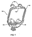
個人防護システム10は、ディアズ(Diaz)らに付与された米国特許第6,481,019号および米国仮特許出願第60/664,900号に開示されている個人防護システム10を改良したものである。これらの特許は、いずれも、参照することによって、ここに含まれるものとする。本発明の個人防護システム10は、図1に示されるように、ユーザの頭14に取付け可能なヘルメットアセンブリ12として実施されている。
The
個人防護システム10は、ユーザ、例えば、医療専門家の頭14および体16とユーザの外部環境との間を通る空気を濾過している。ヘルメットアセンブリ12は、以下に述べるように、ユーザの頭14の周囲に空気を分配するようになっている。さらに具体的には、ヘルメットアセンブリ12は、頭14の前部、すなわち、ユーザの顔と、頭14の後部、すなわち、ユーザの首の両方に空気を分配するようになっている。
The
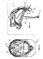
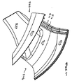
図2を参照すると、ヘルメットアセンブリ12は、ユーザの方を向く内側シェル部18とユーザから離れた方を向く外側シェル部20とを有するシェル17を備えている。外側シェル部20は、内側シェル部18から離間され、少なくとも1つの空気流路26を内側シェル部18と外側シェル部10との間に画定している。本発明は、2つ以上の別個の空気流路26を備えてもよいことを理解されたい。例示された実施形態では、単一の空気流路26が設けられ、以下、この空気流路26に関して、本発明を説明する。シェル17は、好ましくは、アクリロニトリル・ブタジエン・スチレン(ABS)から形成されるとよいが、代替的なプラスチックから形成されてもよい。
Referring to FIG. 2, the
ヘルメットアセンブリ12は、顔面開口42を画定すべく、シェル17から延在する顔面部40も備えている。ヘルメットアセンブリ12の顔面部40は、顎バー44から構成されている。顎バー44は、柔軟性を有し、ポリプロピレンのようなプラスチックから形成されている。顎バー44の柔軟性によって、着用者が外部物体をヘルメットアセンブリ12と接触させたとき、着用者の顔が保護され、衝撃が吸収されることになる。また、顎バー44は、フード92(図1)を着用者の顔から離れた位置で保持している。
The
II. ヘルメット
図2および図3を参照すると、ヘルメットアセンブリ12は、シェル17の空洞38内に取り付けられたファンモジュール46を備えている。ファンモジュール46は、スクロールハウジング48に取り付けられたファン50およびモータ52を備えている。モジュール46を空洞38内に保持するために、締付け具Mがシェル17を通ってハウジング48のネジ孔(図示せず)にねじ込まれるようになっている。ファンモジュール46を覆うために、カバープレート47がシェル17の空洞38の下方に固定されている。カバープレート47とファンモジュール46の基部との間には、クッション49が配置されている。このクッション49は、ファンモータ52から放出される音を吸収するものである。これによって、本発明のシステム10から放出される騒音の程度を低減させることが可能となる。スクロールハウジング48は、振動を低減させるために、ガラス充填ポリプロピレンから形成されるとよい。
II. Helmet With reference to FIGS. 2 and 3, the
ヘルメットアセンブリ12は、外側シェル部20に取り付けられた吸気グリッド100をさらに備えている。吸気グリッド100は、ヘルメットアセンブリ12の外側シェル部20から離間した上面を備えている。吸気グリッド100は、シェル17の前部と後部との間では、外側シェル部20の外形に適合する輪郭を有している。空気は、ファン50によって、吸気グリッド100を通って、スクロールハウジング48内に吸い込まれるようになっている。
The
図3には、ヘルメット12を構成するそれぞれの要素を一緒に固定する種々の締付け具およびワッシャー(図示せず)が示されている。
FIG. 3 shows various fasteners and washers (not shown) that secure together the elements that make up the
作動中、ファン50が、モータ52によって回転され、空気を吸気グリッド100を通してスクロールハウジング49の空気入口64内に吸い込む。この空気は、スクロールハウジング48の2つの互いに離間した開口から排出される。図3Aに示される第1の開口51は、スクロールハウジング48の前部に位置している。開口51から排出された空気は、開口25内に直接流れ、次いで、空気流路26に入る。この通路26から、空気は、シェル17の前部における内側シェル部18と外側シェル部20との間の出口開口35を通って排出される。
In operation, the
第2の開口53は、図3Bに最もよく示されるように、スクロールハウジング48の後部に位置している。開口53から排出された空気は、スクロールハウジング48の後部に取り付けられたマニホールド内に流れる。このマニホールドから、空気は、2つの下方に向けられたノズルを通って排出される。マニホールドおよびノズルは、図3における単一ユニットSとして形成されている。システム10が着用されると、ノズル排出口は、着用者の首の後方に隣接して配置されることになる。
The
内側シェル部18と外側シェル部20との間に画定された空気流路26は、前部空気出口を有する前部34で終端している。さらに具体的には、内側シェル部18および外側シェル部20は、前部34に向かって収束し、前部空気出口を画定している。前部空気出口は、外側シェル部20と内側シェル部18との間に画定された空気偏向部を有していてもよい。具体的には、前部空気出口において、ユーザの頭14の前部に向かって空気を適切に偏向させるために、外側シェル部20を内側シェル部18に向かって傾斜させることによって、空気偏向部を得ている。このような空気偏向部は、米国特許第6,481,019号に最もよく示されている。この特許は、前述したように、参照することによって、ここに含まれるものとする。空気流路26は、前部空気出口に達したときに、拡散するものである。この空気流路26の収束および拡散によって、ユーザの頭14の周りに供給される均衡の取れた空気流を維持することが可能となる。究極的には、これによって、ヘルメットアセンブリ12内の空気流による騒音を最小限に抑えるか、または完全になくす効果が得られる。
An
図2、図3、図4および図8を参照すると、調整可能なヘッドバンド128が示されている。ヘッドバンド128は、ユーザの頭14および首の緊張力を最小限に抑えるのに役立つようにされている。具体的には、ヘルメットアセンブリ12を種々の大きさの頭14に装着するように調整したときでも、ファン50およびモータ52の重量をユーザの首の上方に保持することによって、ユーザの頭14および首の緊張力(strain)および回転力が、最小限に抑えられる。ヘッドバンド128は、シェル17から剛性的に延びる後部支持体130を備えている。後部支持体130は、ヘルメットアセンブリ12に接続された別の部分でよいし、またはヘルメットアセンブリ12と一体の部分でもよいことを理解されたい。後部支持体130は、後部支持体130を後部36に接続する第1および第2の剛性コネクタ132を備えている。好ましい実施形態では、後部支持体130は、内側シェル部18の後部36に接続され、そこから延在している。以下、後部支持体130を、この内側シェル部18に接続されるとして、説明する。しかし、後部支持体130は、シェル17のどのような部分に接続され、その部分から延在してもよいことを理解されたい。
With reference to FIGS. 2, 3, 4 and 8, an
第1の側部136および第2の側部138を有する調整セグメント134は、ヘッドバンド128の一部でもある。必ずしも必要ではないが、好ましくは、調整セグメント134は、後部支持体130に設けられている。好ましい実施形態では、調整セグメント134は、後部支持体130と一体または同一の部品である。代替的な実施形態では、調整セグメント134は、後部支持体130に単純に取り付けられる別の部品である。いずれの場合でも、調整セグメント134は、開口140を画定している。これらの開口140には、内側シェル部18の前部34に柔軟に接続されてそこから延在するストラップ142の第1の端144および第2の端146のそれぞれが、挿入されるようになっている。第1の端144は、調整セグメント134の第1の側部136内に配置され、第2の端146は、調整セグメント134の第2の側部138内に配置されている。好ましくは、第1の端144は、調整セグメント134の第1の側部136内に移動可能に配置され、好ましくは、第2の端146は、調整セグメント134の第2の側部138内に移動可能に配置されている。しかし、以下の説明から理解されるように、第1の端144が、調整セグメント134の第1の側部136内に移動可能に配置され、第2の端146が、調整セグメント134の第2の側部138内に固定して配置されてもよい。代替的に、第1の端144が、調整セグメント134の第1の側部136内に固定して配置され、第2の端146が、調整セグメント134の第2の側部138内に移動可能に配置されてもよい。
An adjustment segment 134 having a
ストラップ142は、後部支持体130の調整セグメント134の反対側に、第1の端144と第2の端146との間に延在する前部分148を備えている。ストラップ142を内側シェル部18の前部34に柔軟に接続するために、少なくとも1つの支持アーム150が、ストラップ142の前部分148から柔軟に延在している。これらのアーム150は、頭14を支持するアセンブリ用のヒンジとして作用している。好ましくは、ストラップ142の前部分148から延在する2つの支持アーム150が設けられている。このような場合、2つの支持アームは、互いに等距離で、内側シェル部18の前部34およびストラップ142の前部分148に接続されている。ストラップ142の前部分148と内側シェル部18の前部34との間には、間隙152が存在している。
The
III.トーガ(外衣)およびフード
図5を参照すると、個人防護システム10は、体16の実質的に全てを覆う体部分90を有するトーガ88を備えている。トーガ88は、頭およびヘルメットアセンブリ12を覆うフード92を備えている。体部分90は、ユーザの体16のどのような部分をも覆うように、下方に延ばすことが可能である。例えば、体部分90は、ユーザの腰またはユーザの足首に至るまで、下方に延ばすことができる。フード92は、ユーザと外部環境との間に流れる空気を濾過するフィルター要素94を備えている。また、前述したヘルメットアセンブリの顔面部40は、フード92をユーザの頭14から離れた個所で保持するようになっている。吸気グリッド100によって、フィルター媒体94は、外側シェル部20およびファン50から離間されている。
III. Toga (Outerwear) and Hood With reference to FIG. 5, the
当技術分野に知られているように、フードユニットは、完全なトーガとは別の覆いとして設けられてもよい。この種のフードユニットは、着用者の頭の周囲にバリアを設ける必要があるときにのみ、用いられている。 As is known in the art, the hood unit may be provided as a separate cover from the complete toga. This type of hood unit is only used when it is necessary to provide a barrier around the wearer's head.
透明な顔面シールド96によって、ユーザは、フード92を通して外を見ることが可能である。顔面シールド96は、顔面シールド96の透視力を高めるために、反射防止被膜および/または屈折防止被膜を備えていてもよい。図5に示されるように、ユーザが個人防護システム10を着用したとき、顔面シールド96は、ヘルメットアセンブリ12の顔面部40および顔面開口42を覆うように、フード92に取り付けられる。顔面シールド96は、フード92内に縫い付けられている。ヘルメットアセンブリ12の顔面開口42は、顔面シールド96を受ける。本発明のこの態様では、ヘルメットアセンブリ12の顔面部40は、顔面開口42を覆うように、顔面シールド96を顔面部40に取り付けることをさらに容易にする面ファスナー(hook-and-loop fastener)を備えている。
A
IV.光アセンブリおよびファンアセンブリ
図3および図7〜図19に示されるように、個人防護システム10は、光アセンブリ200を備えている。光アセンブリ200は、フード92の外に投射する光ビームを生じさせるために、フード92内の顔面シールド96の背後に配置されている。光アセンブリがフード92内に配置されるので、手術室の殺菌状態を維持するために光アセンブリを最新の注意を払って清浄にする必要がない。光アセンブリ200は、レンズ(図示せず)に隣接して配置された光生成ユニット、すなわち、光源201を備えている。
IV. Light Assembly and Fan Assembly As shown in FIGS. 3 and 7-19, the
光源は、好ましくは、1つまたは複数の発光ダイオード(LED)である。LEDは、白光を生じるものである。本発明の一態様では、光は、5500°Kの色温度で放射されるようになっている。このスペクトルの光は、昼の光と等しく、組織の真の演色をもたらしている。光ハウジング202が、LEDおよびレンズを支持し、かつ包囲している。1つの適切な光アセンブリ200は、カルフォルニア州のミッション・ビエホのペリオプティクス(PeriOptix)社によって製造されているペリルックス(PeriLux)LEDである。代替的に、光源は、白色灯または当技術分野において知られている他の適切な光源でもよい。1つの有力な代替案は、ユーザのいずれかの位置に取り付けた光源およびその光源からの光を光ハウジングに運ぶ光ファイバーケーブルを用いることである。
The light source is preferably one or more light emitting diodes (LEDs). The LED generates white light. In one aspect of the invention, the light is emitted at a color temperature of 5500 ° K. This spectrum of light is equivalent to daylight, resulting in a true color rendering of the tissue. A
レンズは、円形である。本発明のいくつかの態様では、光源201に対するレンズの長手方向位置は、選択的に設定されるようになっている。これによって、ユーザは、光アセンブリ200から放射される光ビームを選択的に収束/拡散させることが可能となる。多くのレンズ変位アセンブリを用いることができるが、その一例として、回転カラー(collar)が挙げられる。カラーを第1の方向に回転させることによって、光を小領域に集中させるように、レンズを移動させることが可能となっている。カラーを反対方向に回転させることによって、放射される光が大きな領域にわたって拡散されるように、レンズを移動させることが可能となる。カラーのこの回転は、手動によってなされてもよいし、または収束サーボモータによってなされてもよい。電気サーボモータの制御については、以下、さらに詳細に説明する。
The lens is circular. In some aspects of the invention, the longitudinal position of the lens relative to the
光アセンブリ200は、光角度調整機構204を備えている。この調整機構204によって、ユーザは、光ビームの方向を変更し、これによって、光ビームを特定位置に導くことが可能となっている。具体的には、光ハウジング202は、2つの平行脚210(図7には、1つが図示)に旋回可能に取り付けられている。剛性ブロック209が、脚210と一体に形成され、それらの脚210から下方に延在している。ブロック209は、ストラップ142の前部の外面に取り付けられている。脚210の端を貫通するピン211によって、光ハウジング202が、脚に旋回可能に保持されている。
The
半剛性ケーブル216が、光ハウジング202の旋回運動を調節している。ケーブル216は、シース(図示せず)内に内蔵されている。ケーブルクランプAWおよびリベットPは、協働して、シースの前端を内側シェル部18の露出面に保持している。シースの後端は、シース内に含まれるケーブル216と共に、シェル17の開口を通って、内側シェル部18と外側シェル部20との間の空洞内に延在している。リングクランプAZが、ハウジングの前部の最近位側に配置されている。リングクランプ(図8では、要素206として示されている)の互いに対向する端が、シェル17に向かって上方に延在している。細長のネジ217(図3)が、リングクランプ206の端間に延在し、これによって、リングクランプAZを光ハウジング202に圧縮固定している。ケーブル216の前端は、リングクランプ206の端部間において、ネジBAの露出した部分の周りに巻かれている。
A
図10に示されるように、シェル17の内側に配置されたレバーアーム214が、ケーブル216を選択的に伸縮させている。レバーアーム214は、ピン(図示せず)によって、シェル17(図9)の外側に配置された調整ノブ212に接続されている。このピンは、シェル外側部を貫通している。ケーブル216の近位端、すなわち、後端が、レバーアーム214のピンから遠位側の端に取り付けられている。従って、ノブおよびレバーアームアセンブリの回転によって、ケーブルを伸縮させることが可能となる。このケーブルの運動によって、光ハウジング202をピン211によって画定された軸を中心として旋回させることが可能である。
As shown in FIG. 10, the
光ハウジング202、特に、光源201は、前部空気出口開口35の真下に配置されている。このように配置することによって、開口35から排出される空気が、光アセンブリ200の周囲の温風を光アセンブリから外に吹き出している。これによって、加熱された空気が光アセンブリの近傍に滞留するのを低減させることが可能となる。代わって、加熱された空気は、フード92から外に排出されることになる。この加熱された空気を除去することによって、光アセンブリによって生じた熱が個人防護システム10の着用者を過度に暖める程度を低減できることになる。
The
本発明のこの構造のさらに他の特徴は、光源201によって放出される熱によって、光アセンブリ200の温度が上昇する程度を最小限に抑えることにある。光源201を比較的低温に保持することによって、光源自体が、比較的効率的な発光体として機能することができる。(LED式光源の発光効率は、LEDの温度の上昇と共に低下する)。
Yet another feature of this structure of the present invention is to minimize the extent to which the temperature of the
図20を参照すると、モータ52および光源201用の制御回路が、ブロック図で示されている。電源70は、モータおよび光源の両方に電圧を印加している。本発明の代替的態様では、電源70は、1対の電源に分割されてもよく、各電源が、個々にモータ52または光アセンブリ200に電力を供給するようにしてもよい。
Referring to FIG. 20, a control circuit for the
電源70は、好ましくは、少なくとも1つのセル(すなわち、バッテリ)である。これらの少なくとも1つのセルは、再充電可能であるとよい。しかし、再充電可能でない(すなわち、使い捨て)セルが用いられてもよい。本発明の一態様では、電源70は、6VDCの電圧を供給している。しかし、代替的に、他の電圧であってもよい。
The
第1の電源70は、好ましくは、図5に示されるように、ユーザの体16に取り付けられている。第1の電源70をトーガ88の外部に取り付けることによって、医学的/外科的手術中、第1の電源70を容易に取換え可能である(すなわち、切換え可能である)。本発明のいくつかの態様では、電源70は、トーガ内のアクセス可能な個所に配置されている。代替的に、第1の電源70は、ヘルメットアセンブリ12内に配置、すなわち、内蔵されてもよい。
The
図20を再び参照すると、個人防護システム10は、ファンモータ52の作動を調整するファン制御回路224をさらに備えている。このファン制御回路224を作動させるために、電圧レギュレータ220が、一定の電圧信号を制御回路224に加えている。電圧レギュレータ220は、電源から受ける6VDCの電流を調整している。本発明の一態様では、電圧レギュレータ220は、ファン制御回路224を作動させる3.3VDCの電流を供給するようになっている。
Referring back to FIG. 20, the
光制御回路は、光源のオン/オフ状態および光源から放射される光の強度の両方を制御するために、光源201に作動信号を選択的に供給するものである。図20において、光制御回路が、電流レギュレータ230として示されている。電流レギュレータ230は、電圧レギュレータ222から一定の電圧印加信号を受信するものである。発明の一態様では、電源70に接続された電圧レギュレータ222は、3.6VDC信号を電流レギュレータ230に供給している。
The light control circuit selectively supplies an activation signal to the
本発明のいくつかの態様では、電圧レギュレータは、ファン制御回路と光制御回路の両方に共通の一定電圧をもたらしている。本発明のいくつかの態様では、電圧が調整された印加信号をファン制御回路または光制御回路のいずれかに供給する必要がない。従って、本発明のいくつかの態様では、ファン制御回路および光制御回路の片方または両方が、電源70から直接電力が供給されることになる。
In some aspects of the invention, the voltage regulator provides a constant voltage common to both the fan control circuit and the light control circuit. In some aspects of the invention, it is not necessary to provide a voltage regulated applied signal to either the fan control circuit or the light control circuit. Thus, in some aspects of the invention, one or both of the fan control circuit and the light control circuit will be powered directly from the
ファン制御回路224は、ファンモータ電圧レギュレータ220およびモータ52に電気的に接続されている。ファン制御回路224は、電流をファンモータ電圧レギュレータ220から受け、その電流をモータ52およびファン50の速度を制御するように調整している。
The
本発明の例示的な態様では、ファン制御回路224は、モータ52およびファン50の速度を制御するために、パルス幅変調(PWM)を行なっている。PWMを行なうために、ファン制御回路224は、マイクロコントローラ118およびパワートランジスタ226を備えている。マイクロコントローラ118は、複数の入力端および出力端を備えている。2つのスイッチ120,122は、マイクロコントローラ118の個々の入力端に電気的に接続されたプッシュボタンである。(なお、スイッチと関連するプルアップレジスタは、図示されていない)。ユーザは、プッシュボタンを押し、ファン50の所望の速度(その結果として、所望の空気流)を調整するようになっている。スイッチは、ヘルメットアセンブリ12の側部に取り付けられたプッシュボタンの形態にあり、ユーザがフード92内に手を延ばすことにより、容易に操作可能である。
In an exemplary embodiment of the invention,
ファン50の所望の速度に基づいて、トランジスタを選択的にオンオフ操作するために、マイクロコントローラ118の少なくとも1つの出力端が、パワートランジスタ226に電気的に接続されている。さらに具体的には、トランジスタに供給される印加信号は、一定の周波数および所望のファン速度と正比例する可変デューティサイクル値を有するPWM信号である。
At least one output of the
パワートランジスタ226は、本発明の一態様において、実際には、1対のパワーMOSFET(個々のMOSFETは、図示せず)である。ここで、第1のMOSFETはP型であり、第2のMOSFETはN型である。第1のMOSFETのドレインは、電源の正の入力端子に接続されている。第1のMOSFETのソースは、ファンモータ52に接続されている。第1のMOSFETのゲートは、レジスタを介して、バッテリの正の端子に接続されている。第1のMOSFETのゲートに、第2のMOSFETのドレインも接続される。第2のMOSFETのソースは、アース端子に接続されている。第2のMOSFETのゲートは、マイクロコントローラ118から延びる制御ラインに接続されている。従って、第2のMOSFETゲートの信号が、第1のMOSFETを開閉することになる。カルフォルニア州のE1セガンドのインターナショナル・レクチファイア(International Rectifier)によって製造されているパワーMOSFET「IRF730TR」は、パワートランジスタ226を構成するP型MOSFETおよびN型MOSFETの両方を一括して含む単一パッケージである。勿論、当業者であれば、パワートランジスタ226を他の形態で実施することが可能であることを認めるだろう。
In one aspect of the present invention, the
マイクロコントローラ118は、好ましくは、カルフォルニア州サンジョセのアトメル(Atmel)社によって製造されているモデル「ATmega8」である。「ATmega8」は、内蔵PWMサポートを備えている。他の適切なマイクロコントロ−ラ118またはマイクロプロフェッサも、当業者には明らかだろう。以下に詳細に説明するように、マイクロコントローラ118は、ファン50の速度を制御する機能とは別の機能を果たすのに用いられてもよい。
The
本発明の一態様では、モータ52を通る電流が、PWM率を決めるフィードバック信号として用いられる。レジスタ(図示せず)は、モータ52とアース端子との間に接続されている。レジスタの両端の電圧が、モータ速度を表す値として、マイクロコントローラ118に供給されるようになっている。モータ速度は、パルスの一定の全期間(オン/オフ)ごとにパルスのデューティサイクルの比率を変化させることによって、調整されている。
In one aspect of the invention, the current through the
また、マイクロコントローラ118は、集束サーボモータおよび光角度サーボモータに電気的に接続されてもよい。これによって、光を調整する必要性をなくすことが可能となる。
The
ヘルメットアセンブリ12内に流れる空気の容積を制御するのに加えて、本発明は、ファンが最小流量または最大流量の空気を送給するときを示す可聴表示をもたらしている。この可聴表示は、モータに送給されるPWM信号の周波数を瞬間的にリセットすることによって、得られるものである。これによって、モータは、人の耳に検知可能な音を放出するようにシャフトを回転させる速度で、作動されることになる。この音が、空気の最小容積および最大容積を示す可聴表示をユーザにもたらしている。すなわち、本発明によれば、ヘルメットアセンブリ12内に流れる空気が最小容積または最大容積に達したとき、ユーザに可聴ピング音(ping)がもたらされることになる。
In addition to controlling the volume of air flowing into the
また、制御ボタンの1つを押すのに応じて、制御回路224がファンモータ52の速度を増減するたびに、このピング音がもたらされてもよい。モータ速度の上限および下限において、制御装置は、2つのピング音が短い時間を隔てて同一周波数で生じるようにモータを作動するように、構成されている。これによって、ユーザは、最大モータ速度または最小モータ速度の設定がなされたことを知ることが可能となる。
This ping sound may also be provided each time the
可聴ピング音は、短期間にわたって、例えば、0.1〜0.2秒間にわたって、ファンモータをモータが可聴音を生じる周波数で運転することによって、生じる。例えば、モータの正常な作動中、制御回路224によって加えられる作動信号の一定周波数は、30.3kHzである。(モータの速度を変化させるために)、第1のデューティサイクルでの作動信号の出力から第2のデューティサイクルでの作動信号の出力への移行間に、261Hz〜523Hzの周波数の作動パルスが、モータに50%のデューティサイクルで供給される。作動パルスがこの周波数で供給される結果、モータの速度が、感知できるほど明らかに低下することになる。これによって、モータ52は、人の耳に検知可能な音色を放出することになる。
The audible ping sound is generated by operating the fan motor at a frequency at which the motor produces audible sound over a short period of time, for example, 0.1 to 0.2 seconds. For example, during normal operation of the motor, the constant frequency of the actuation signal applied by the
本発明のいくつかの態様では、ピング音を生成するためにモータが作動される周波数は、モータを運転するために設定される新しい速度範囲と共に変化している。例えば、本発明のこの態様の一実施形態では、制御回路224がモータ速度を増大するため、モータ作動信号のデューティサイクルを増大させる前に、この制御回路224が、まず高周波数のピング音生成作動信号を供給する。これによって、比較的高周波数のピング音信号が生じることになる。また、モータ速度を減少させるため、制御回路224が作動信号のデューティサイクルを減少させる前に、この制御回路224は、低周波数のピング音生成作動信号を供給する。これによって、モータ52から、低周波数ピング音が生じることになる。従って、外科医は、ファン速度がリセットされることを示す可聴表示を受けるのみならず、もしその速度が増減した場合、それに関する表示を受けることも可能となる。
In some aspects of the invention, the frequency at which the motor is operated to produce a ping sound is changing with a new speed range set to operate the motor. For example, in one embodiment of this aspect of the invention, since the
しかし、モータが選択的に作動される周波数は、可聴表示を与える限り、補助具を用いない人の耳の可聴範囲(30Hz〜20kHz)内にあればよいことを理解されたい。この作動速度の周波数であれば、ファンモジュール46のモータ52の種々の構成要素は、その周波数で振動し、これによって可聴表示を生成することになる。
However, it should be understood that the frequency at which the motor is selectively actuated need only be in the audible range (30 Hz-20 kHz) of a person's ear without the aid of providing an audible indication. At this operating speed frequency, the various components of the
代替的に、ファン制御回路224は、PWMを利用する代わりに、モータ52およびファン50の速度を制御するために、一般的に可変レジスタまたはバリスタとも呼ばれるポテンシオメータを備えていてもよい。当業者に知られているモータ52およびファン50の速度を変化させるさらに他の実施態様が、代替的に利用されてもよい。
Alternatively,
ヘルメットアセンブリ12内には、印刷回路基板228(PCB)が配置されている。このPCB228は、電圧レギュレータ220,222、マイクロコントローラ118、および関連する電子装置を支援している。PCB228は、当業者に知られているように、PCB228に取り付けられた電気接続部品に繋がる導通路を備えている。
A printed circuit board 228 (PCB) is disposed in the
個人防護システム10は、電圧とは無関係に、光源に一定電流をもたらす光電流レギュレータ230も備えている。電流を一定に保つことによって、光源は、第1の電源70のセルが枯渇し、電圧低下を生じても、明るさが低下しない安定した照明をもたらすものである。光電流レギュレータ230は、好ましくは、光ハウジング内において光アセンブリ200と一体化されている。しかし、光電流レギュレータ230は、PCB228上に配置されていてもよい。
The
個人防護システム10は、電源70のセルの出力が低下したときをユーザに警告する低電力検出回路も備えている。好ましい実施形態では、1対のレジスタを備える分圧回路232が、第1の電源70に電気的に接続されている。1対のレジスタの接合点の信号が、入力信号として、マイクロコントローラ118に供給されるようになっている。指示器234が、マイクロコントローラ118の出力の1つに電気的に接続されている。この指示器234は、好ましくは、ヘルメットアセンブリ12内またはユーザの視野内に取り付けられる表示LEDであるとよい。また、指示器234は、ユーザによって聞き取れる可聴信号を生じるラウドスピーカ、またはラウドスピーカとLEDの組合せでもよい。代替的に、指示器234は、前述したように、ファンを振動させ、可聴信号を生成させるために、パワートランジスタ226を選択的に作動および非作動させる構成と置き換えられてもよい。
The
V.通信ユニット
図22〜図27を参照すると、個人防護システム10は、通信ユニット236も備えている。通信ユニット236は、他の通信ユニット236との間で無線通信を行なっている。他の通信ユニットは、他の個人防護システム10と一体化されてもよいし、または1つまたは複数の独立型ユニットとして実施されてもよい。通信ユニット236によって、個人防護システム10のユーザ間の便利な音声通信が可能になる。
V. Communication Unit Referring to FIGS. 22 to 27, the
通信ユニット236は、マイクロフォン238、スピーカ240、および送受信機242を備えている。通信ユニット236は、第2の電源244も備えている。第2の電源244は、送受信機242に電力を供給するものである。第2の電源244は、好ましくは、少なくとも1つのセルである。これらの少なくとも1つのセルは、好ましくは、再充電可能であるが、再充電可能ではないセルが用いられてもよい。少なくとも1つのセルは、単一のセルでもよいし、互いに接続された複数のセルでもよい。送受信機242および第2の電源244は、多くの場合、一緒にパックされ、ユーザの体16に取付け可能である。
The
代替的に、図26に示されるように、送受信機242は、第1の電源70に電気的に接続されている。この場合、ユーザは、多数の電源を所有する必要がない。本発明のこれらの態様では、第3の電圧レギュレータ241が、第3の一定電圧信号を送受信機242に供給している。この第3の電圧は、ファン制御回路224および光制御回路(電流レギュレータ230)に供給される調整電圧と異なっている。送受信機242は、代替的に、ヘルメットアセンブリ12内に配置されてもよい。
Alternatively, the
マイクロファン238は、音声を電気信号に変換するものである。マイクロフォン238によって生じた信号は、送受信機242に供給されることになる。送受信機242は、好ましくは、高周波(RF)信号を送受信することができるRF送受信機242である。送受信機242は、電気信号をRF信号に変換し、このRF信号を送信するようになっている。この送信されたRF信号は、他の通信ユニットの送受信機242によって、受信されることになる。送受信機242は、受信したRF信号を電気信号に変換することになる。スピーカ240は、送受信機242に電気的に接続され、送受信機242から電気信号を受信するものである。スピーカ240は、電気信号をユーザが聴き取れる音声波に復号することになる。
The
マイクロフォン238は、ヘルメットアセンブリ12の顎バー44に取り付けられている。マイクロフォンによって生じた信号を伝達させる(仮想線で示される)ケーブル239も、同様に顎バー44に配置されている。マイクロフォンは、ヘルメットの他の個所に取り付けられてもよい。
本発明の一態様では、スピーカ240は、イアホーンである。イアホーンは、ユーザの耳に取り付けられるように形作られたフックを備えている。既存の音声生成変換器を有する芽部(bud)がフックに取り付けられている。芽部は、ユーザの外耳道に隣接して位置するか、または外耳道内に位置するように、形成されている。音声信号を芽部に供給する音声信号ケーブルが、ヘルメットに取り付けられている。しかし、ケーブルの前端は、ヘルメットには取り付けられていない。これによって、イアホーンとヘルメットシェル17との間にある程度の柔軟性が得られることになる。この柔軟性によって、個々のユーザの体格の差を調整することができる。また、この柔軟性によって、ユーザは、本発明の個人防護システム10の使用中、イアホーンを適所に保持しながら頭を動かすことが可能となる。また、多数の取付けアセンブリが、ヘルメット内に設けられている。これによって、イアホーンをシステム10のユーザのいずれかの耳に挿入して取り付けることが可能となる。
In one embodiment of the present invention, the
本発明の一態様では、送受信機242は、900MHz域で作動するようになっている。個々の送受信機は、デジタル拡散スペクトルRF信号を交換する。通信ユニット236は、好ましくは、全二重(full duplex)で作動するようになっている。すなわち、送受信機242は、同時にRF信号を送信および受信することができる。適切な送受信機242の一例として、ロードアイランド州ナラガンセットのイエーテック(Eartec)によって製造されている「STx1000」が挙げられる。アラバマ州オーバーンのコーチコム(Coachcomm)も適切な送受信機システムを市販している。これらのシステムによれば、3人以上のユーザが、本発明の外科用個人防護システム10を同時に使用し、送受信機を用いて、全二重モードで互いに通信することが可能となる。任意のユーザが他のユーザと通信するために、プッシュトーク(push-to-talk)スイッチを押す必要がない。従って、この個人防護システム10は、ユーザのグループ(3人以上)が、防護フード92による音声減衰およびファン50およびモータ52によって生じる騒音を上回るように声を高める必要もなく、通常のグループ会話におけるように、互いに会話することが可能となる。
In one embodiment of the present invention, the
図27は、本発明の代替的な送受信機242aを示すブロック図である。送受信機242aは、マイクロフォン238から受信した音声信号をRF信号に変換させる変調器252を備えている。変調器252によって生じたRF信号は、通信ユニットアンテナ237によって放送されることになる。アンテナ237には、送受信機復調器254も接続されている。復調器254は、受信したRF信号を音声信号に変換し、この音声信号が、スピーカ240を作動させるのに用いられている。
FIG. 27 is a block diagram illustrating an
変調器252および復調器254の作動は、送受信機242aの一部でもある送受信機制御装置256によって、制御されている。この送受信機制御装置256は、従来のデジタルマイクロプロフェッサ、すなわち、PLAまたはDSPでもよい。送受信機制御装置254は、3人のユーザによって作動されるスイッチ258,260,262の状態に部分的に基づいて、変調器252および復調器254の作動を調整するようになっている。本発明の個々の防護システム10は、復調器254を効果的に遮断(turn off)するために、1つのスイッチ、例えば、スイッチ258を作動させることが可能となっている。ユーザは、もし通信ユニットを用いている他のユーザによって放送される通信の受信を望まない場合、この手段を取る。もしユーザがこの状態で送受信機242aの作動を望む場合、送受信機制御装置256は、これに応じて、復調器254を非作動にすることができる。代替的に、送受信機制御装置256は、ユーザがスピーカ240の非作動を望んでいることに応じて、FET(図示せず)を作動させ、これによって、復調器254から生じた音声出力信号を消去することもできる。
The operation of the
また、送受信機制御装置256は、復調器252によって、RF信号の出力を選択的に無効にすることが可能となっている。防護システム10を用いるユーザは、近くのユーザと放送ではなく会話をしたい場合、復調器252がRF信号を音声信号で放送するのを一時的に停止することを望むことがある。RF信号から変調された音声信号の選択的な放送を調整するために、スイッチ260が作動されることになる。送受信機242aが音声信号を放送するのをユーザが望んでいないのに応じて、送受信機制御装置256は、一時的に、変調器252の作動を停止している。代替的に、FET(図示せず)を切り替えることによって、送受信機制御装置256は、マイクロフォンからの音声信号を変調器252に送るのを選択的に阻止してもよい。
Further, the
また、送受信機制御装置256は、他の通信ユニット236のどの1つまたは複数のグループが送受信機242aから生じた信号を受信することができるかを制御するように、変調器252を調整することも可能である。例えば、個々の送受信機が直接拡散スペクトルプロトコルを用いて信号を交換する本発明の態様では、送受信機制御装置256は、出力信号の変調および入力信号の復調を行なうのに用いられるコードを調整している。個々の送受信機が周波数ホッピング拡散スペクトルプロトコルを用いて信号を交換する本発明の態様では、送受信機制御装置256は、搬送周波数の周波数ホッピングパターンを成立させるコードを生成している。スイッチ262は、通信ユニットのどの1つまたは複数のグループが信号を交換および/または受信することができるかを成立させるように作動する制御部材である。
The
以下、図28を参照して、本発明による個人防護システムが選択的に信号を交換するのに有用であることを説明する。ここでは、5つの通信ユニット236a〜236eが示されている。随意的に、通信ユニット236dをこの選択的な送信/受信能力を有する1つのユニットであるとする。従って、スイッチ262を押すと、関連する送受信機制御装置256が、通信ユニット236dの送受信機242aを、放送された音声信号が残りのユニットの全て、すなわち、236a,236b,236c,236eまたはユニット236eのみに受信されるように、設定する。これによって、外科医は、システム10を着用している他のユーザとの通信に対していくらかプラバシーを持つことが可能となる。代替的に、これによって、外科医の助手は、外科医を妨げることなく、他のユーザと通信することが可能となる。
In the following, referring to FIG. 28, it will be described that the personal protection system according to the present invention is useful for selectively exchanging signals. Here, five
図28には、レシーバ264も示されている。このレシーバは、1つまたは複数の通信ユニット236a〜236aによって放送された信号を受信することができる。レシーバ264によって受信された音声信号は、ラウドスピーカ266を通して、放送されてもよい。これは、教育環境において、望ましい。代替的に、音声信号は、レコーダ265によって貯蔵されてもよい。ここでも、放送信号の選択的な変調によって、任意の送受信機242aによって放送された信号を復調するレシーバの能力を選択的に調整することが可能となる。
FIG. 28 also shows a
図27を再び参照すると、ユニットプロセッサ272が、送受信機制御装置256に接続されていることが分かる。受信したRF信号から復調器254によって抽出されたデジタル信号は、送受信機制御装置256に送られる。復調器252は、送受信機制御装置256から受信したデジタル信号を放送RF信号に組み込むことができる。主に、送受信機制御装置256は、ユニットプロセッサ272によって受信したデジタル信号を送信すると共に、ユニットプロセッサによって用いられるデジタル信号を送るための中間プロセッサとして機能している。本発明のいくつかの態様では、送受信機制御装置256およびユニットプロセッサ272は、単一ユニットである。
Referring again to FIG. 27, it can be seen that the unit processor 272 is connected to the
デジタルRF信号は、図28に示される固定RF送受信機274によって交換されている。送受信機274は、手術室内の通信バス266に接続されている。この通信バスに接続される他のユニットとして、以下に述べる手術室制御ヘッド278およびパーソナルコンピュータ280のような機器が挙げられる。このような1つの手術室制御ヘッド278は、本出願の譲渡人によって「SIDNE」の登録商標で市販されている。この構成によって、送受信機242aは、外科用保護システム10の他の構成要素と遠隔装置との間で信号を交換するユニットとして機能することが可能である。図28において、手術室制御ヘッドは、固定レシーバ264から音声信号を受信する形態で示されている。本発明のいくつかの形態では、送受信機264,274は、単一ユニットである。
Digital RF signals are exchanged by a
例えば、外科医は、マイクロフォン238に向かって、「集光(Focus Light)」のコマンドを告げることが可能である。これらの言語による音声信号は、送受信機242aによって、手術室制御ヘッドに伝送されることになる。手術室制御ヘッドは、音声信号を処理し、コマンドを復号するようになっている。このコマンドが解釈されると、手術室制御ヘッドは、送受信機274を介して、送受信機242aにコマンドデータパケットを送ることになる。送受信機242aは、コマンドメッセージを取り込み、そのメッセージをユニットプロセッサ272に送っている。ユニットプロセッサ272は、コマンドを受信すると、適切な制御信号を生成し、光アセンブリ200と一体のレンズを変位させるように、使用されるサーボモータを作動させることになる。
For example, the surgeon can tell the microphone 238 a “Focus Light” command. Audio signals in these languages are transmitted to the operating room control head by the
ファンモータ52の速度は、同様に、本発明の内蔵システムによって、調整されるようになっている。
Similarly, the speed of the
通信ユニット236aは、手術室内の他の機器、例えば、外科用機器の音声作動制御、および手術室環境設定(HVACおよび光)を行なうこともできる。さらに具体的に、マイクロフォン238に音声によって入力されたコマンドが、送受信機242aおよびレシーバ264によって、手術室制御ヘッド261に伝送される。次いで、手術室制御ヘッドは、適切な指示パケットを生成し、このパケットが、バス276を介して、指示を実行する適切な装置に出力されている。
The
本発明のシステムの総合的な構成によれば、個人防護システム10は、その作動状態に関する情報を報告することも可能である。図28において、分圧器232を形成する2つのレジスタの接合点の信号が、ユニットプロセッサ272に供給されている。この接合点の信号が電源70に貯蔵された電荷が低下していることを示すレベルにまで降下した場合、ユニットプロセッサ272は、これらのデータを含むデータパケットを生成することになる。データパケットは、送受信機制御装置256に送られ、送受信機242aによって放送される。データパケットは、送受信機274によって受信されることになる。このパケットは、パーソナルコンピュータ280に送られる。これによって、手術室内のユーザに、特定のユーザによって消費されている特定の電源70が寿命に近いこと、従って、この特定の電源70が取換えられるべきであることが知らされることになる。
According to the overall configuration of the system of the present invention, the
VI.代替的ヘッドユニット
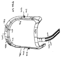
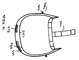
図29〜図34は、フード92を着用者の頭および上体の周りに支持する代替的な支持構造体を示している。この特定の支持構造体は、ヘッドユニット270である。ヘッドユニット270は、ヘッドバンド272を備えている。このヘッドバンド272に、通気ユニット274および光源276(図49)が調整可能に取り付けられている。通気ユニット274内に送り込まれた空気は、それぞれ、前側ノズルアセンブリ280および後側ノズルアセンブリ282内に排出されるようになっている。ヘッドバンドに対する通気ユニット274の調整能力によって、ユニットの構成要素、主に、通気ファン438を、ユニットが着用者に加える物理的な緊張力が最も小さくなるように、着用者の体に配置することが可能である。
VI. Alternative Head Unit FIGS. 29-34 show an alternative support structure that supports the
さらに具体的には、ヘッドユニット270は、いくらかの柔軟性を有するプラスチックから形成される顔面フレーム286を備えている。本発明の一態様では、顔面フレーム286は、ポリプロピレンまたはナイロンから形成されている。図35に最もよく示されるように、顔面フレーム286は、前額バンド288を有すべく、形成されている。前額バンド288は、個々の着用者の前額に適合すべく設計された湾曲を有している。図示しないが、詰め物が前額バンド288の内面に固定されてもよい。顔面フレーム286は、前額バンド288の両端から下方に延在する支持ポスト290を有している。顔面フレーム286の一部でもある顎バー292が、2つの支持ポスト290の両下端間に延在している。顎バー292は、ポスト290間のガード部の前側がポストから前方に延在するような湾曲形状を有している。
More specifically, the head unit 270 includes a
また、支持ストラップ294も、顔面フレーム286の一部である。支持ストラップ294は、略矩形ストラップの形態にあり、前額バンド288の中心から上方に延在している。以下に説明するように、支持ストラップ294は、着用者の頭の上方で通気ユニット274を保持する部材である。
The
取付けピン296が、顔面フレーム286の支持ポスト290の各々から外方に延在している。各取付けピン296は、関連する支持ポスト290の外面から外方に延在するステム(図示せず)を有している。各取付けピン296、その自由端をなす大径ヘッド部298も有している。取付けピン296は、フードと一体の透明シールドを固定して支持するものである。
A mounting
ヘッドストラップ302が、顔面フレーム286の前額バンド288の各端から後方に延在している。前額バンド288およびヘッドストラップ302は、全体として、ヘッドバンド272を形成している。ヘッドストラップ302は、ナイロン66のような極めて柔軟なプラスチックから形成されている。図36から分かるように、各ヘッドストラップ302は、比較的広い幅を有する基部306を備えている。基部306は、前額バンド288の関連する端の内面に対して着座されるようになっている。2つの開口308が各ヘッドストラップ302の基部306を貫通している。これらの開口308には、ヘッドストラップ302を顔面フレーム286に保持する締付け具(図示せず)が嵌入されるようになっている。本発明の例示した態様では、皿孔(図示せず)が、各開口308の周りに形成されている。
A
各ヘッドストラップ302の基部306から、脚310が下方に延在している。各脚310は、その脚が繋がっている基部306の幅よりも小さい幅を有している。各ヘッドストラップ302は、脚310の自由端から延在するラック312を有している。ラック312は、その長軸から側面に沿って突出する一組の歯(図示せず)を有している。図36は、ヘッドユニット270の左側のヘッドストラップ302を示している。このヘッドストラップ302は、ラック歯が下方に突出するように形成されている。ヘッドユニット270の右側のヘッドストラップ302は、ラック歯が上方に突出するように形成されている。各ラック312の自由端から、先端部314が直角に突出している。各先端部314は、関連しているラック歯が突出するのと同じ方向に突出している。
A
後側ノズルアセンブリ282は、ファン433から流出する流れを着用者の首の下方に導くためのもので、両方のヘッドストラップ302を一緒に保持している。後側ノズルアセンブリ282は、シェル320およびシェル320の長軸を中心として回転するチップ318を備えている。
The rear nozzle assembly 282 guides the flow out of the fan 433 below the wearer's neck and holds both head straps 302 together. The rear nozzle assembly 282 includes a
以下、図37および図38を参照して、後側ノズルアセンブリシェル320について説明する。シェル320は、単一のプラスチック片から形成され、3面幹部322を有し、この3面幹部322から、2つの翼部324が延在している。さらに具体的には、幹部322は、2つの互いに向き合った側壁328内に湾曲する後壁326を有すべく、形成されている。シェル320は、両側壁328が内方に向かって漸減するように、さらに形成されている。その結果、シェル320は、底部よりも上部の方が広い。シェル320は、2つの互いに離間されたリブ330,332を有すべく、さらに形成されている。リブ330,332は、シェルの内面において、一方の側壁から他方の側壁に向かって横方向に延在している。リブ330は、シェル320の開端の周りに配置されている。リブ332は、リブ330と平行で、かつリブ330の下方に配置されている。
Hereinafter, the rear
後側326および側壁328の内面から、プレート334が延在している。プレート334は、側壁328の内縁に向かって延在するが、その内縁を超えて突出しないようになっている。開口336が、プレート334を貫通している。この開口336は、シェル後壁326および側壁328によって画定された空洞を長手方向に貫通する軸に沿って位置決めされている。
A
剛性の管状スリーブ340が、シェル320の後壁326と側壁328との間の空洞内に突出するように、後壁326から内方に延在している。このスリーブ340は、後壁326の開口342から延在している。後壁326は、壁外面から突出する開口342と同心で、その開口342から半径方向に離間された環状リング344を有するように、さらに形成されている。このリング344には、開口342に向かって内方に延在する互いに離間した歯346が形成されている。
A rigid
各シェル翼324は、基部側壁328の各々から延在している。翼324は、基本的には、3つの壁からなる構造体である。3つの壁は、それらの開面が、前方、従って、顔面フレーム286を向くように、配置されている。複数の互いに離間した補強ウエブ350は、各翼324およびその翼324が突出する幹部の側壁328によって画定された空洞を貫通している。ウエブ350は、横方向、すなわち、シェル320を通る上下方向の長軸と直交する方向に延在している。
Each
後側ノズルアセンブリ282の一部でもあるプレート352が、シェル320によって画定されている開いた空洞の全体にわたって延在している。以下、図39を参照して、プレート352について説明する。このプレート352は、略凹凸輪郭のパネル部分354を有している。パネル部分354は、内方に向かって漸減する側縁(図示せず)を有すべく、さらに形成されている。パネル部分354は、互いに対向する上側縁および下側縁が外方に向かって半円状に湾曲するように、さらに形成されている。また、パネル部分354は、湾曲した隅部を有すべく、形成されている。
A
プレート352は、パネル部分354の内面(図39に見られる面)から外方に延在する2つの4面補強フレーム356を有すべく、形成されている。各補強フレーム356は、パネル部分354の内面から外方に延在している。各フレーム356は、2つの互いに平行に離間した上側リブ358および下側リブ358を有している。各フレームの一端において、パネル部分354の隣接する側縁に沿って位置する外側リブ360が、リブ358間に延在している。各フレーム356の互いに対向する内端において、側部に向かって湾曲した内側リブ362が、上下リブ間に延在している。
孔364は、パネル部分354の中心を貫通している。パネル部分354は、孔364を囲む環状リブ366を有している。プレート352は、フレームの内側リブ362が孔364と同心の湾曲中心を有すべく、さらに形成されている。
The
パネル部分354の底から、脚368が外方に突出している。これらの脚368は、プレート352の最も下の構造要素をなす平面基部369を有している。脚369の互いに対向する端からパネル部分354の底端の隣接部分に向かって、段部370が延在している。各段部370からパネル部分354の底端の隣接する部分に沿って、短寸リップ372がわずかな距離だけ延在している。パネル部分354の内面に沿って、補強ウエブ374が延在している。ウエブ374は、リップ372の互いに対向する自由端間に延在している。ウエブ374は、補強フレーム356の2つの一直線に並ぶ底リブ358から平行に離間されている。従って、最下端リブ358とウエブ374との間には、スロット359が画定されている。
A
プレート352は、3面カラー378も有している。この3面カラー378は、パネル部分354と一体化され、そのパネル部分354の上方に短距離だけ突出している。カラー378は、前壁380を有している。前壁380の互いに対向する端から、2つの側壁382が内方に湾曲している。カラー378に対して、2つの平行なリブ384,386が一体に形成されている。リブ384が、カラー378の前壁380および側壁382の同一平面にある上縁を超えて内方に延在している。リブ384の下方には、リブ386がリブ384から離間して配置されている。
The
各カラー378から、リップ387がパネル部分354の上縁に沿って外方に延在している。リップ387は、パネル部分354の内面から外に突出している。互いに対向するリップ387の端間において、ウエブ390が、パネル部分354の内面から外方に延在している。ウエブ390は、補強フレーム356の直線状に並ぶ互いに対向する上部リブ358の上方に、それらの上部リブ358と平行に配置されている。従って、上部リブ358およびウエブ390によって、スロット392が画定されることになる。
From each
プレート352は、支持アーチ394を有すべく、さらに形成されている。略円形状を有するアーチ394は、パネル部分354の上縁から上方に延在している。アーチの断片は、一定の直径を有しているが、アーチは、平面ではない。アーチ394は、中心に向かって傾斜している。この輪郭は、後頭部の一般的輪郭と略一致している。さらに具体的には、アーチ394の互いに対向する末端部は、各々、カラー378の一端と隣接するパネル側縁との間に配置されている。以下に述べるように、このアーチ394は、通気ユニット274を着用者の頭の上方に弾力的に支持している。
The
後側ノズルアセンブリ280が組立てられると、プレート352は、シェル320の開いた前面に対して配置されることになる。後側ノズルアセンブリ282の一部でもあるノブ396が、シェル320の露出した後面に取り付けられている。図40に最もよく示されるように、ノブ396は、円筒シャフト398を備えている。シャフト398に沿って、互いに円弧状に離間した歯402が、半径方向外方に延在している。ノブ396のシャフト398は、その自由端に開口する孔399を有すべく、さらに形成されている。本発明の一態様では、この孔399は、シャフト398内に同心に配置されたスリーブ401を貫通している。
When the
ノブ396は、シャフト398の一端の周りに配置されたヘッド404も有している。ヘッド404には、ヘッド404内に位置するシャフトの一部の周りに延在するリング406が配置されている。リング406は、シャフト398と同心で、シャフト398から半径方向外方に離間している。リング406は、半径方向において互いに対向する2つの柔軟なタブ408(1つを図示)を有している。各タブ408は、タブの外面に沿って長手方向に延在する単一リブ410を有している。
The
後側ノズルアセンブリ280は、ノブ396のシャフト398がシェルスリーブ340内に着座し、かつシェルスリーブ340を貫通するように、構成されている。シャフト398の自由端は、プレート352内に形成された補強リブ366の周囲の環状空間に着座している。ネジ付き締付け具(図示せず)が、プレート孔364を貫通し、ノブ396と一体の孔399を貫通している。この締付け具によって、パネル352は、シェル320に保持されるようになっている。後側ノズルアセンブリがこのように組立てられると、ノブ396と一体のリブ410は、シェル歯346間の空洞内に着座することになる。
The
ヘッドユニット270が組立てられると、ヘッドストラップのラック312が、シェル320とパネル352との間のスロット内に着座することになる。これは、図30に最もよく示されている。なお、この図では、ヘッドユニットの左右が逆になっていることを理解されたい。具体的には、右側のヘッドストラップ302と一体のラック312は、スロット359内に着座している。一方、左側ヘッドストラップの一部をなすラック312は、スロット392内に着座している。ラック歯は、ノブ歯402と係合するようになっている。
When the head unit 270 is assembled, the
以下、図41を参照して、後部ノズルチップ318について説明する。この後部ノズルチップ318は、管状基部412を備えている。リップ414が、基部412の開端の周りに環状に延在し、かつ基部の外面から突出している。ノズルチップ318は、4つの等距離で互いに離間した取付けタブ416を有している。これらのタブ416は、リップ414から上方に延在している。各タブ416は、先細の外面を有するヘッド418を有している。後側ノズルアセンブリ282が組み込まれると、タブ476は、シェル開口336内にスナップ嵌合されることになる。従って、ノズルチップ318は、開口336を通る軸に対して回転することができる。
Hereinafter, the
ノズルチップ318には、基部412の下側開端を部分的に囲むヘッド420が形成されている。ノズルチップ318は、チップヘッド420が略シェル状で、基部412の開端がこのヘッド420の凹面によって画定された空洞内に開口するように、形成されている。
The
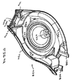
図34を再び参照すると、通気ユニット274が、ファン433およびモータ434をそれぞれ収容する下側シェル428および上側シェル430を備えることが、分かるだろう。図42に最もよく示されるように、下側シェル428は、基部432を備えている。下側シェル428は、基部432が、中心で最も広く、互いに対向する前端および後端で比較的狭くなるように、形成されている。互いに対向する側壁434が、基部432の長手方向の側縁から上方に延在している。シェル基部432は、その中心から上方に延在する円筒状の中空ボス436も有している。ボス436は、ファンモータ434を受入れるように、寸法決めされている。ボス436の中心には、モータの回転シャフトが貫通する開口(図示せず)が形成されている。
Referring again to FIG. 34, it will be appreciated that the
下側シェル428には、上側シェルおよび下側シェルを一緒に保持する締付け具を受入れる2対のポスト438,440が形成されている。ポスト438,440の各々は、シェル基部432から上方に延在している。第1のポスト対であるポスト438は、下側シェル428の前端に隣接して配置されている。各ポスト438は、シェル428の前端において、隣接する側壁434の内方に配置されている。各ポスト440は、シェル428の後部において、隣接する側壁の内方に配置されている。
The lower shell 428 is formed with two pairs of
シェル基部432および側壁434から、これらの基部および側壁の面が画定する後部開口に隣接して、2つの平行リブ442,444が内方に延在している。1つのリブ442は、シェルの後開端の周囲において内方へ延在している。リブ444は、リブ442の前方に、リブ442から離間して配置されている。図示されていないが、同様のリブが、下側シェル428の前端において、基部432および側壁434から外方に突出していることを理解されたい。
Two parallel ribs 442 and 444 extend inwardly from the
下側シェル428は、一組の邪魔板438,440も有している。これらの邪魔板438,440は、ボス436を部分的に囲み、ボス436から半径方向に離間して配置されている。1つの邪魔板438は、略S字形状を有し、シェルの前開端のわずか後ろから内方に緩慢に湾曲している。邪魔板438は、ボス436の軸を中心とする曲率半径を有する領域を有している。邪魔板438のこの特定の領域は、ボス436の周りに略150°の円弧範囲に及ぶ。また、邪魔板438は、S字部分から傾斜した尾部分も有している。邪魔板のこの尾部分は、隣接するシェル側壁434の方に傾斜し、このシェル側壁434と当接している。
The lower shell 428 also has a set of
邪魔板440は、円弧状の輪郭を有している。邪魔板440は、側壁434から邪魔板438の反対側に延在している。邪魔板440は、下側シェル428から前方に離間し、下側シェル428の開端を実質的に覆っている。邪魔板440は、ボス436の周りに略70°の円弧範囲に及んでいる。邪魔板438の円弧部分と隣接する邪魔板440との間には、略5〜10°の円弧状の間隙が形成されている。
The baffle plate 440 has an arcuate outline. The baffle plate 440 extends from the
また、下側シェル428は、基部432が多数の矩形開口442を有すべく、形成されている。これらの開口442によって、以下に述べるように、モータカバー444(図34)を下側シェル428の露出した底面に固定するのが容易になる。
The lower shell 428 is formed so that the
以下、図43を参照して、上側シェル430について説明する。この上側シェル430は、蓋450を備えている。この蓋450から、2つの側壁452が延在している。蓋450は、下側シェル基部432の形状と略一致する形状を有している。下側シェル基部452と同様、蓋450も、その長軸に沿って湾曲している。側壁452は、蓋の長手方向の側縁に沿って延在し、蓋から下方に湾曲している。蓋450には、円形の中心開口453が形成されている。シェル428,430が一緒に組立てられると、開口453が下側シェルボス436と同軸になる。
Hereinafter, the
上側シェル430は、下側シェル428のリブ442,444と同様のリブ454,456,458,460を有すべく、さらに形成されている。2つの平行リブ454,456が、上側シェルの前端において、一方の側壁から他方の側壁に延在している。リブ454は、蓋450および隣接側壁452によって画定された開口内に延在している。リブ456は、リブ454の背後に、リブ454と平行に離間して配置されている。リブ458,460は、上側シェル428の後開口に隣接している(リブのみが、部分的に示されている)。第1のリブ458は、後開口の周りに延在している。第2のリブ460は、リブ458の内方に離間している。
図44および図44Aに示されるように、ファン433は、円形基部462を有している。中空ボス464は、基部462の中心から上方に延在している。ファン基部は、円形であるが、平坦ではない。代わって、基部462は、ボス464によって形成された孔に対して上方に湾曲している。通気ユニット274が組立てられるとき、ファン433は、下側シェル428内に装着され、モータ434に取り付けられ、ファンボス464は、シェルボス436の上方に着座している。モータシャフトが、ファンボス464の中心に取り付けられるようになっている(モータシャフトを固定する手段は、図示せず)。基部462の外周には、多数の円弧状に互いに離間したブレード466が配置されている。
As shown in FIGS. 44 and 44A, the fan 433 has a
ブレード466の上面を覆って、リング468が配置されている。リング468は、断面では平坦であるが、テーパの付いた輪郭を有している。すなわち、リングの内縁は、リングの外縁の上方に位置している。リング468のこの横方向におけるテーパは、ファン基部462と同様のテーパと近似している。中心に向かって高くなるテーパの付いた表面を有するこの輪郭は、頭蓋骨の後端の中心に向かう湾曲と近似している。これは、通気ユニット274が位置決めされるヘッドの一部である。
A
通気ユニット274の一部でもあるグリルユニット470が、上側シェル430の上部を覆って配置されている。図45に示されるように、グリルユニット470は、フレーム472を備えている。フレーム472は、概して、蓋の形状と同様の形状を有している。しかし、フレーム472は、上側シェル蓋450の外面に全体が嵌合するように、寸法決めされている。一組の平坦なプラスチック帯から形成されるフレームは、帯片が内方に向かって傾斜するように、形成されている。従って、フレームを形成する個々の帯片は、上側シェル蓋450の隣接する外面に着座するグリルユニット470の表面をなしている。
A
フレーム472に対して、格子474が一体に形成されている。格子474は、多数の交差ウエブから形成されている。格子474は、蓋開口453およびファン433を覆って延在している。フレーム472から、スナップタブ473が下方に延在しているのが、図示されている。通気ユニット274が組立てられると、スナップタブが上側シェル(図43)の開口475に係止され、グリルユニットを上側シェルに保持することになる。
A lattice 474 is formed integrally with the
図46に最もよく示されているように、モータカバー444が、下側シェルの基部432の露出した下面に装着されるようになっている。モータカバー444は、本体480を有している。本体480は、シート状の形状を有し、本体480の長軸に沿って湾曲している。また、モータカバーの本体480は、長手方向中心軸の中心に向かって湾曲している。ここでも、この湾曲は、通気ユニットが通常着座される頭蓋骨の部分の湾曲と近似している。本体480の前端は、真直縁を有し、その後端は、側縁間で湾曲する輪郭を有している。モータカバー478は、本体480の外周から上方に延在するリップ482を有すべく、さらに形成されている。さらに具体的には、リップ482は、カバー本体480の側縁および後縁に沿って上方に延在している。
As best shown in FIG. 46, a motor cover 444 is mounted on the exposed lower surface of the
4つの脚484が、リップ482に割り込んで形成されている。各脚484は、略L字状の形状を有し、リップ482と同じ方向で上方に延在している。各脚484は、カバー本体480から延在している。脚484の内、2つの脚484は、本体480の前縁の直ぐ後方に配置されている。残りの2本の脚484は、湾曲した後端の前方に配置されている。各脚484は、外方に延在する先端部486を有している。先端部486は、隣接するリップ482の外縁の上方に延在している。モータカバー444は、先端部486をシェル開口442内にスナップ嵌合させることによって、下側シェル428に固定されている。
Four
モータカバー444のリップ482は、各側に1つ、具体的には、後端の前方および後脚484の後端に、間隙489を有すべく、さらに形成されている。
The
モータカバー444の本体480は、その長軸に沿って延在するスロット490を有している。スロット490は、主体の前端から延在している。スロット490は、本体480の後端の前方位置で終端している。モータカバー444は、本体480の前端の直ぐ後に、2つの柔軟なフィンガー492を有している。これらのフィンガー492は、スロット490に対して対称的に配置されている。フィンガー492は、モータカバー444の残りと一体に形成されている。各フィンガー492は、リップ482と同じ方向で上方に延在するチップ494を有している。
The main body 480 of the motor cover 444 has a slot 490 extending along its long axis. The slot 490 extends from the front end of the main body. The slot 490 terminates at a front position at the rear end of the main body 480. The motor cover 444 has two flexible fingers 492 immediately after the front end of the body 480. These fingers 492 are arranged symmetrically with respect to the slot 490. The finger 492 is formed integrally with the rest of the motor cover 444. Each finger 492 has a tip 494 that extends upward in the same direction as the
通気ユニット274は、アーチ394によって、着用者の頭の上方に部分的に保持されている。ヘッドユニット270が組立てられると、アーチ394の上端が下側シェル428の外面とモータカバー444との間に挟み込まれることになる。締付け具(図示せず)が、下側シェル428、従って、通気ユニット274の全体をアーチに保持することになる。モータカバー444が下側シェル428に固定されると、アーチは、モータカバーのリップ482に形成された間隙489を貫通するようになっている。
The
図33および図34に示されるアコーディオン状の後部蛇腹498は、通気ユニット270の後開端から後側ノズルアセンブリ282に至る導管として機能するものである。通気ユニット端において、後部蛇腹498は、下側シェル428および上側シェル430のそれぞれの端によって形成された略楕円状の開口を貫通している。後部蛇腹498の最前部のリブ(図示せず)は、互いに整合して隣接する上側シェルリブ458,460および下側シェルリブ442,444によって画定された開口を囲むスロット内に着座するようになっている。
The accordion-shaped rear bellows 498 shown in FIGS. 33 and 34 functions as a conduit from the rear open end of the ventilation unit 270 to the rear nozzle assembly 282. At the end of the ventilation unit, the rear bellows 498 passes through a substantially elliptical opening formed by the respective ends of the lower shell 428 and the
後部蛇腹498の後端は、後側ノズルアセンブリのシェル幹部322およびプレートカラー378の隣接する上端によって画定された楕円状の開口内に着座するようになっている。後部蛇腹498の最後部リブは、互いに隣接するシェルリブ330、332およびカラーリブ384,386によって画定された開口を囲むスロット内に着座するようになっている。
The rear end of the rear bellows 498 is adapted to seat within an elliptical opening defined by the
前側ノズルアセンブリ280は、ペデスタル502およびキャップ504を備えている。図47に最もよく示されているように、ペデスタル502は、中空ポスト506を備えている。ポスト506は、略矩形の断面輪郭を有している。ポスト506の基部は、顔面フレームの支持ストラップ294の一部、具体的には、前額バンド288のすぐ上方の部分に固定されている。この固定を行なう締付け具は、図示されていない。
The
ポスト506の上方において、ペデスタル502は、ヘッド508を有している。このヘッドは、ペデスタルの前部、後部、および側部から外方に延在する平面基部510を有している。ヘッド508は、基部510の互いに対向する長手方向の2つの側部から上方に湾曲する側壁512で終端している。基部510および側壁512の内面から、2つのリブ514,516が内方に延在している。リブ514は、ペデスタルヘッド508の後端の周囲に配置されている。リブ516は、リブ514の前方に、リブ514と平行に配置されている。
Above the post 506, the pedestal 502 has a head 508. The head has a
キャップ504は、ペデスタルヘッド508を覆って着座するようになっている。前側ノズルアセンブリ280は、このキャップ504で終端している。図48を参照すると、キャップ504は、上パネル518を有することが分かる。この上パネル518から、2つの側パネル520(片方のみを図示)が下方に湾曲している。キャップ504は、上パネル518がその長軸に沿って湾曲するように、さらに形成されている。前側ノズルアセンブリ280が組み込まれると、キャップの側パネル520は、ペデスタルヘッドの側パネル512の上縁と当接することになる。
The
前側ノズルアセンブリのキャップ504は、リブ519がキャップの上パネル518の長軸に沿って延在するように、さらに形成されている。リブ519は、両側から内方に延在するスロット521(1つのスロットのみを図示)を有すべく、形成されている。上パネル518の前端から、タブ524が上方に延在している。従って、タブ524は、リブ519の直前に配置されている。タブ524から、小形ウエブ525が、タブ524と直交して、リブ519の方に延在している。このフランジ525は、リブ519の長軸から上方に延在している。タブ524の直ぐ背後において、細長スロット523がリブ519に形成されている。
The
図示されないが、キャップの上パネル518および側パネル520の内面から、1対のリブが内方に延在していることを理解されたい。これらのリブの内、第1のキャップリブは、ペデスタルリブ514と当接するようになっている。第2のキャップリブは、ペデスタルリブ516と当接するようになっている。
Although not shown, it should be understood that a pair of ribs extend inwardly from the inner surfaces of the top panel 518 and side panel 520 of the cap. Of these ribs, the first cap rib comes into contact with the
図31および図34に最もよく示されるように、後部蛇腹498の構造と同様、前部蛇腹528が、導管として機能している。この導管を通して、通気ユニット274から送り込まれた空気が、前側ノズルアセンブリ280に流出することになる。前部蛇腹内の最後部リブが、互いに隣接する下側シェルリブ(図示せず)および上側シェルリブ454,456によって画定されたスロット内に着座するようになっている。前部蛇腹528内の最前部リブは、互いに隣接するペデスタルリブ514,516およびキャップ504に形成された相補的なリブによって画定されたスロット内に着座するようになっている。
As best shown in FIGS. 31 and 34, similar to the structure of the rear bellows 498, the front bellows 528 functions as a conduit. Through this conduit, the air fed from the
以下、図29および図31を参照して、支持ストラップ294を説明する。この支持ストラップ294は、通気ユニット274を着用者のヘッドの上方に保持するのに役立つものである。具体的には、支持ストラップ294は、下側シェル428の下方で、モータカバー444の前開端を貫通している。図35を参照すると、支持ストラップは、2列の平行開口532を有していることに、留意されたい。開口532は、支持ストラップ294を横切って水平に延在している。開口532のこれらの対は、ストラップの長さに沿って、すなわち、長手方向に沿って、互いに離間している。
Hereinafter, the
支持ストラップ294が下側シェル428とモータカバー444との間に配置されると、フィンガーチップ494が、1対の互いに対向するストラップ開口532に着座することになる。このモータカバー444の支持ストラップ294への係合によって、着用者の上方に、通気ユニット274用の前支持体が得られるようになっている。
When the
後部ノズルアッセンブリのアーチ394の柔軟性によって、通気ユニット274は、ユニットの後部ノズルアッセンブリ282の後部取付け部を中心として、旋回することが可能となっている。モータカバーのフィンガー492は、柔軟である。これは、通気ユニット274の位置が、前側ノズルアセンブリ280から比較的近い位置または遠い位置に選択的に設定されることを意味している。総括的に述べると、通気ユニット274のこの調整能力は、ユニットが着用者のヘッドに対して相対的に配置されること、従って、着用者の緊張力が最も少なくなることを意味している。
The flexibility of the rear
通気ユニット274の重心が第7頚椎の比較的近くに位置するという事実によって、着用者の緊張力が低減されている。これは、下側シェル428、上側シェル430、ファン433、モータカバー444、およびグリルユニット470のような構成要素を、それらの中心から下方に延在するように形成されることによって、達成される。前述したように、この形状化は、頭蓋骨の後部、すなわち、通気ユニットが典型的に装着される頭の一部に近似している。
The fact that the center of gravity of the
本発明が着用者の緊張力を最小限に抑える他の理由は、ヘッドユニットが比較的軽量であることである。ヘッドバンド272、通気ユニット274、前側ノズルアセンブリ280、後側ノズルアセンブリ284、および顔面フレーム286を備えるヘッドユニット270は、典型的には、450g未満の重量を有している。本発明のさらに好ましい態様では、このアセンブリは、400g未満の重量を有している。
Another reason that the present invention minimizes the wearer's tension is that the head unit is relatively lightweight. Head unit 270 comprising headband 272,
この緊張力を最小限に抑えることに関して、ヘッドを取り付けた機器による実験によって、もし質量中心が第7頚椎の上方に配置されたとき、緊張力が最小に保たれるのが分かっている。結果的に、このヘッドユニット270の着用者は、ユニットの質量中心が可能な限り、この目印の上方に配置されるように、構成することができる。ここでも、着用者の頭の大きさとは無関係に、この配置を達成することができる。 With regard to minimizing this tension, experiments with a head-mounted instrument have shown that if the center of mass is positioned above the seventh cervical vertebra, the tension is kept to a minimum. As a result, the wearer of the head unit 270 can be configured so that the center of mass of the unit is located above the mark as much as possible. Again, this arrangement can be achieved regardless of the size of the wearer's head.
ヘッドバンド272の大きさの調整およびヘッドバンドに対する通気ユニット274の配置/配向とは無関係に、前側ノズルアセンブリ280の排出口は、前額バンド288に対して一定位置に維持されている。これは、前側ノズルアセンブリから懸垂される透明シールドが、前額バンド288、従って、着用者の顔から一定距離を保って配置されることを意味する。従って、前側ノズルアセンブリから排出される空気流は、ヘッドユニット270の大きさとは無関係に、着用者の顔から一定距離だけ離れた位置を通ることになる。これは、ヘッドユニット構成とは無関係に、空気が着用者の顔に対する適当な位置に排出されることを確実にすると共に、顔から離れる方向にCO2を適切に排出し、比較的冷気のある空気を送ることを確実にするように、前側ノズルが配置されていることを意味している。
Regardless of the size adjustment of the headband 272 and the placement / orientation of the
前側ノズルアッセンブリ280を顔の前の比較的一定の位置に維持することによって、フード/トーガの配置と関連するさらに他の利点が得られる。以下に述べるように、フード/トーガの顔面シールド590(図52)は、前側ノズルアッセンブリ280から懸垂されている。ここでも、このアッセンブリ280は、顔に対して比較的一定の位置に保持されるので、透明シールド590も、同様に、顔から一定距離だけ離れた位置に保持されている。これは、シールド590が、ヘッドユニットとは無関係に、光源276の光または大気光のいずれかの眩しさを最小に保持するような位置に配置され得ることを意味している。
By maintaining the
同様に、ヘッドユニットの調整とは無関係に、後側ノズルアセンブリ282は、着用者の首から本質的に一定距離だけ離れた位置に保持されている。これによって、ヘッド寸法およびヘッド形状とは無関係に、チップ318から排出される空気が首を最適に冷却することが確実になる。
Similarly, regardless of the adjustment of the head unit, the rear nozzle assembly 282 is held at a position that is essentially a fixed distance away from the wearer's neck. This ensures that the air exhausted from the
透明シールド590を顔から本質的に一定距離だけ離れた位置に配置する他の利点は、ヘッド寸法とは無関係に、視野が本質的に一定となるように、シールドを寸法決めすることができることである。本発明の理想的な構成では、どのような態様のヘッドユニットおよびフード/トーガであっても、透明シールド590の視野内に入ることがない。これによって、システムを用いることによるユーザの閉所恐怖症の感覚を低減させることができる。 Another advantage of placing the transparent shield 590 at an essentially constant distance from the face is that the shield can be sized so that the field of view is essentially constant regardless of the head dimensions. is there. In the ideal configuration of the present invention, any form of head unit and hood / toga does not fall within the field of view of the transparent shield 590. Thereby, the user's sense of claustrophobia by using the system can be reduced.
支持ストラップ294は、その尾端に、下方を向いた小タブ295(図50)を有している。このタブは、モータカバー内に形成されたスロット490を貫通している。このタブは、支持ストラップ294が、通気ユニット274内に延在している程度または通気ユニット274から後退している程度の視覚的な表示をもたらすものである。
The
図49に示されるように、光源276は、LED(図示せず)または他の発光要素を含む内蔵式ユニットである。光源276は、前額バンド288に取り付けられたブラケット540に旋回可能に取り付けられている。具体的には、ブラケット540は、平坦な基部542を備えている。支持ストラップ294の直ぐ下方で、締付け具(図示せず)が、ブラケット基部542を顔面フレームの前額バンド288に保持している。2つのアーム544が、基部542から斜め下方に延在している。光源は、ブラケットアーム544の自由端間に枢動可能に取り付けられている。
As shown in FIG. 49, the
光源276の上向き角/下向き角は、支持ワイヤ546によって制御されるようになっている。このワイヤは、前側ノズルアセンブリの上部のリブ519に摺動可能に取り付けられた小タブ548から延在している。タブ548は、リブスロット521内に着座する脚(図示せず)を有している。スロット内に脚を嵌め込む配置によって、リブ519の長さに沿ったタブ548の摩擦嵌合を容易にし、これによって、タブを左の位置に摺動させることができる。
The upward / downward angle of the
ワイヤ546は、タブ548からキャップ開口523を通して光源ユニット276に延在している。光源276の上向き/下向き位置の旋回配置は、タブ548の位置を前側ノズルアセンブリ280の長さに沿って調整することによって、設定されている。
The wire 546 extends from the tab 548 through the cap opening 523 to the
図50を参照すると、可撓性回路560が、顔面フレームの顎バー292の内面に取り付けられている。可撓性回路560は、2つの低電力指示LED562,564およびマイクロフォン566を支持している。図示されないが、LED562,564およびマイクロフォン566に延在する導体路が可撓性回路に積層されていることを理解されたい。
Referring to FIG. 50, a flexible circuit 560 is attached to the inner surface of the
さらに具体的には、図35を再び参照すると、ポスト290および顎バー292の周りの顔面フレーム286は、内方を向いたリップ568を有することが分かるだろう。可撓性回路560は、略矩形状の本体570を有している。可撓性回路本体570と一体の3つのフィンガー572が、本体の上側側面に沿った長手方向に離間した箇所において、本体から上方に延在している。LED562,564は、可撓性回路の2つの外側フィンガー572の外面に取り付けられている。各LED562,564は、顔面フレームの顎バーのリップ568内に形成された別の開口574を貫通している。
More specifically, referring again to FIG. 35, it can be seen that the
マイクロフォン566は、可撓性回路の中心側に位置するフィンガー572に取り付けられている。このフィンガー572は、可撓性回路本体570に重なるように巻かれている。キャップ(図示せず)が、可撓性回路を覆うように、顎バー292を覆って嵌合されている。マイクロフォン566は、着用者の口に導かれるように、このキャップの開口を貫通している。
The microphone 566 is attached to a
第1のLED、例えば、LED562は、電力モニター指示器234(図22)の機能を果たしている。従って、バッテリが殆ど消耗したことを電力モニター回路が決定するたびに、LED562が照らされることになる。 The first LED, eg, LED 562, performs the function of the power monitor indicator 234 (FIG. 22). Thus, each time the power monitor circuit determines that the battery is almost exhausted, the LED 562 will be illuminated.
第2のLED564およびマイクロフォン566は、ヘッドユニット270内の通信ユニットと関連する。マイクロフォン566は、着用者の音声を電気信号に変換するものである。送受信機制御回路256は、通信システムを「ミュート」モードにするように、スイッチ258を作動している。
Second LED 564 and microphone 566 are associated with a communication unit in head unit 270. The microphone 566 converts the wearer's voice into an electrical signal. The
図51に示されるように、システムを制御するために着用者が作動するスイッチ578,580,582は、顎バー292に取り付けられている。これらのスイッチ578,580,582は、シリコンゴムから形成され、炭素接点を有している。第1のスイッチ578は、顎バー292によって画定された第1の開口584内に取り付けられている。残りの2つのスイッチ580,582は、顎バー292の第2の開口586内に取り付けられている。
As shown in FIG. 51, switches 578, 580, and 582 that are actuated by the wearer to control the system are attached to the
可撓性回路の本体570は、顎バーの開口584,586を覆って配置されている。可撓性回路560のこれらの表面には、スイッチの炭素接点(図示せず)が当接する導体路が形成されている。第1のスイッチ578は、スイッチ258と類似の機能を果たしている。このスイッチ578は、通信システムをミュートモードに設定し、またはミュートモードから解除するように、作動させられている。残りの2つのスイッチは、スイッチ120,122と類似している。従って、これらのスイッチ580,582は、通気ユニットファン278の速度を調整するために、押されることになる。
The flexible circuit body 570 is positioned over the jaw bar openings 584,586. On these surfaces of the flexible circuit 560 are formed conductor tracks against which the carbon contacts (not shown) of the switch abut. The first switch 578 performs a function similar to the
スイッチ578,580,582の上記の配置の利点は、スイッチが着用者のすぐ前に位置することである。これによって、着用者が手をヘッドに向かって移動させ、スイッチを作動させることが、比較的容易になる。従って、このユニット270を着用しているユーザは、スイッチを作動させるために、ユーザの手を殺菌範囲から外に移動させる必要がない。
An advantage of the above arrangement of
図52は、ヘッドユニット270と共に用いられるフードまたはトーガに取り付けられた透明シールド590を示している。シールド590の外周内のフードまたはトーガを形成する殺菌材料が固定される位置が、破線で示されている。シールド590の上部は、タブ592を有すべく、形成されている。タブ592は、スロット状の開口594を有している。開口594は、矩形の形状を有し、シールド590の緯度、すなわち、左右軸と平行な軸上にある。開口594は、上方に延在する拡張スロット595をさらに有している。拡張スロット595は、シールド590の緯度、すなわち、上下軸上に沿って配置されている。
FIG. 52 shows a transparent shield 590 attached to a hood or toga used with the head unit 270. The position where the sterilizing material forming the hood or toga in the outer periphery of the shield 590 is fixed is indicated by a broken line. The top of the shield 590 is formed to have a
シールド590は、2つの円形開口596を有すべく、形成されている。各開口596は、シールド590の側縁と底縁との間の遷移縁として機能する湾曲縁の上方において、シールド590の側縁に隣接して配置されている。切込み598が、各開口596から半径方向に延在している。開口594,596は、シールド590の周囲部分に位置することが理解されるだろう。これは、殺菌フードまたはトーガを形成する材料によって被覆されるシールド部分である。
The shield 590 is formed to have two circular openings 596. Each opening 596 is disposed adjacent to the side edge of the shield 590 above the curved edge that functions as a transition edge between the side edge and the bottom edge of the shield 590. A
フードまたはトーガがヘッドユニット270に装着されると、シールドがヘッドユニットを覆って配置され、前側ノズルアセンブリ280と一体のタブ524がシールド開口598内に挿入されることになる。前側ノズルアセンブリのウエブ525は、開口している拡張スロット595内に着座している。シールド590を固定タブ524およびウエブ525を覆って着座させることによって、シールドをヘッドユニット270の外側要素と直線状に配置し、このように配置されたシールドの回転を阻止することが可能となる。
When the hood or toga is attached to the head unit 270, the shield is placed over the head unit and the tab 524 integral with the
シールド590は、顔面フレーム286の周りに湾曲して配置されている。このシールド590の可撓性によって、シールド開口594の各々を顔面フレームのピン296の各々と直線状に配列させることが可能となる。シールド開口594は、取付けピン296のヘッド298の直径よりも小さい直径を有している。従って、このとき、シールド590は、ピン296の周囲にスナップ嵌合されることになる。この係合によって、シールド590および関連するフードまたはトーガは、ヘッドユニットに固定されることになる。
The shield 590 is arranged around the
本発明のこの態様では、シールド590の最上取付け部とタブ524との間に少なくとも3cmの間隔があり、シールドは、2つの横方向に離間したピン296に取り付けられている。この構成によって、シールドがヘッドユニット270に装着されたとき、シールドの曲率半径は、上下方向の長軸に沿って変化することになる。さらに具体的には、タブに隣接するシールドの上部の曲率半径は、比較的大きい。ピン296間では、シールドは、より小さい曲率半径を有し、従って、より湾曲している。
In this aspect of the invention, there is a spacing of at least 3 cm between the top mount of the shield 590 and the tab 524 and the shield is attached to two laterally spaced pins 296. With this configuration, when the shield is attached to the head unit 270, the radius of curvature of the shield changes along the long axis in the vertical direction. More specifically, the radius of curvature of the top of the shield adjacent to the tab is relatively large. Between
この構成の利点は、目の高さの近くにおいて、シールドは、それほど湾曲されず、従って、比較的平坦な輪郭を有することによって、眩光を最小限に抑えることが可能となっている。また、この構成は、シールドがフード/トーガを形成する材料を着用者の前額および頭頂から離れて懸垂させるのを助長するように機能している。この特徴によって、比較的大きい透明シールドとフードとの間の自由空間が、頭頂の周囲に得られることになる。これによって、補助機器、例えば、ヘッドアップディスプレイ、カメラ、他の通信装置、または光源を着用者の頭の周囲に装着するのが容易になる。 The advantage of this configuration is that near the eye level, the shield is not very curved, and thus has a relatively flat profile, thereby minimizing glare. This configuration also serves to help the shield suspend the hood / toga forming material away from the wearer's forehead and from the top of the head. This feature provides a free space between the relatively large transparent shield and the hood around the top of the head. This makes it easy to wear auxiliary equipment, such as a head-up display, camera, other communication device, or light source around the wearer's head.
本発明のこの構成の他の利点は、開口594,596が、シールド590をヘッドユニット270に保持するシールド590と一体の手段として機能することにある。この構成によって、ヘッドユニットへのシールドの取付けを容易にすべく、スナップヘッド、磁石、またはフック・イン・ファブリック(hook-in-fabric)締付け帯をシールドのフード/トーガに設ける必要性をなくすことが可能となる。これらの締付け部材をなくすことによって、これらの要素をシールドに設けることに関連するコストを削減することができる。
Another advantage of this configuration of the present invention is that the
VII.代替的光源、通信およびファンユニット
図53は、本発明のいくつかの態様において、本発明の個人防護システム10の多数の構成要素がいかに単一のハウジング610に含まれるかを示す線図である。ハウジング610は、ユーザのいずれかの箇所に着用されるように、構成されている。例えば、ハウジング610は、クリップ(図示せず)を備え、ベルトのような衣類品に取り付けられてもよい。代替的に、ハウジング610は、ストラップ(図示せず)を備え、これによって、ユーザに取り付けられてもよい。
VII. Alternative Light Source, Communication and Fan Unit FIG. 53 is a diagram illustrating how, in some aspects of the present invention, multiple components of the
ハウジング610内には、電源70が配置されている。また、送受信機242がハウジングと一体化されている。ユーザの頭まで延びるケーブル612は、マイクロフォン238およびスピーカ240に接続される導体を備えている。本発明のこれらおよび他の態様では、マイクロフォンおよびスピーカは、フードを懸垂するのに用いられる構造から離れて、ヘッド内に組み込まれている。ハウジング610内には、ファン52aも配置されている。ファンから供給される空気流の大半は、可撓性管614内に排出されるようになっている。管614は、空気を排出させる人体支持構造体内の出口孔に接続されている。
A
光生成ユニット616もハウジング610内に含まれている。光生成ユニット616の例として、LEDまたはハロゲン電球のような白熱電球が挙げられる。光ファイバーケーブル618が、光生成ユニット616から延在している。光ファイバーケーブルの遠位端が、人体支持構造に取り付けられた発光ヘッド628に取り付けられている。
A
本発明のこの態様では、ファン52aからの空気流が、2つの出口(図示せず)から排出されるようになっている。管614の近位端は、出口の1つに接続されている。第2の出口は、ハウジングのダクト622に繋がっている。ダクト622は、光生成ユニット616におけるシステム10の着用者にもっとも近いサブハウジング302の面と、ハウジング610の隣接する構造壁との間に配置されている。従って、システムは、新しい空気をダクト298内に連続的に吹き込むように、ファン52aを作動させている。空気は、ハウジング610の側内に形成された排気口624から排出されるようになっている。この空気の一定の供給によって、光生成ユニット616によって生成した熱がハウジング610および着用者の体の隣接する部分を輻射によって暖める程度を最小限に抑えることができる。
In this aspect of the invention, the airflow from the fan 52a is exhausted from two outlets (not shown). The proximal end of
本発明のこの態様の利点は、個人防護システム10の作動要素の重量の大半が、このような重量が著しい物理的な緊張力を生じることがないユーザの腰または他の人体部から懸垂されることである。
An advantage of this aspect of the invention is that the majority of the weight of the actuating element of the
VIII.代替的特徴
図面を参照して説明したヘルメット以外のフードを懸垂する人体着用支持構造体が、本 発明に用いられてもよい。有力な1つの構造体として、肩に取り付けられるフレームが挙げられる。フードを支持する構造部材が、このフレームに含まれている。この支持構造体には、ファンまたは光生成ユニットが直接取り付けられてもよい。ファンおよび光生成ユニットの両方が支持構造体にこのように取り付けられる本発明の態様では、ファンによって排出される空気の一部を光生成ユニットの周りに循環させるために、ダクトが配置されている。本発明の支持構造体のこの態様の代替的実施形態は、単に、空気を受入れるダクト、空気を排出させる出口、および光を放射する発光ヘッドを有していればよい。本発明のこれらの態様では、腰に取り付けられるユニットが、ファンおよび光生成ユニットを含んでいる。
VIII. Alternative Features A body-worn support structure that suspends a hood other than the helmet described with reference to the drawings may be used in the present invention. One powerful structure is a frame attached to the shoulder. A structural member that supports the hood is included in the frame. A fan or light generation unit may be directly attached to the support structure. In embodiments of the invention in which both the fan and the light generating unit are thus attached to the support structure, a duct is arranged to circulate a portion of the air exhausted by the fan around the light generating unit. . Alternative embodiments of this aspect of the support structure of the present invention need only have a duct for receiving air, an outlet for exhausting air, and a light emitting head that emits light. In these aspects of the invention, the unit attached to the waist includes a fan and a light generating unit.
本発明のいくつかの態様によれば、人体支持構造体は、着用者の胴体の周りに着用されたベストに類似した衣類を備えている。この衣類には、フードを懸垂させる2つ以上の支持体が一体化される。 According to some aspects of the present invention, the human body support structure comprises a garment similar to a vest worn around the wearer's torso. The garment is integrated with two or more supports for suspending the hood.
また、本発明のいくつかの態様では、支持ユニットが、外向きのスピーカを備えてもよい。例えば、このスピーカは、可撓性回路560に取り付けられてもよい。本発明のこれらの態様では、マイクロフォン566によって生じた信号を増幅することができる増幅器も配置されている。これらの信号は、このスピーカによって、フード/トーガを介して周囲環境に放送されるようになっている。この構成によって、RF信号送受信機を設ける必要性をなくすことが可能となる。 In some embodiments of the present invention, the support unit may include an outward speaker. For example, the speaker may be attached to the flexible circuit 560. In these aspects of the invention, an amplifier is also provided that can amplify the signal produced by the microphone 566. These signals are broadcast by this speaker to the surrounding environment via a hood / toga. With this configuration, it is possible to eliminate the need to provide an RF signal transceiver.
音を伝達する少なくとも1つの部分をフード/トーガの透明シールドに設けるのも望ましい。(一般的に、透明シールドを形成する材料は、音を吸収するかまたは反射する)。すなわち、着用者の口と略一直線に並ぶ開口が、透明シールドに形成されてもよい。この開口は、フード/トーガの残りを形成する殺菌材料の一部によって、被覆されている。この構成によって、着用者の音声を放送するかまたは増幅するアセンブリを設ける必要性をなくすことができる。 It is also desirable to provide at least one portion for transmitting sound in the hood / toga transparent shield. (In general, the material forming the transparent shield absorbs or reflects sound). That is, an opening that is substantially in line with the wearer's mouth may be formed in the transparent shield. This opening is covered by a part of the sterilizing material that forms the rest of the hood / toga. This arrangement eliminates the need for an assembly that broadcasts or amplifies the wearer's voice.
代替的に、透明シールドの開口は、音波を吸収し、かつ再伝達する材料によって、被覆されてもよい。このような機能を果たす材料として、シリコンゴムのような電気測定材料が挙げられる。 Alternatively, the opening of the transparent shield may be coated with a material that absorbs and retransmits sound waves. An example of a material that performs such a function is an electrical measurement material such as silicon rubber.
同様に、空気を通気ファンから光生成ユニットに導くために、他のダクトアセンブリが設けられてもよいことを理解されたい。例えば、光源に直接通じる前側ノズルアセンブリまたは後側ノズルアセンブリのいずれかの中に、ダクトが配置されているとよい。このダクトが、光源に至る導管にまで延在している。導管は、可撓性であるとよい。本発明のいくつかの態様では、この導管が光源のハウジングの内部に開口している。従って、空気は、光源ハウジング内の熱を発生する発光要素または熱シンク要素を直接通り過ぎることになる。 Similarly, it should be understood that other duct assemblies may be provided to direct air from the ventilation fan to the light generation unit. For example, a duct may be placed in either the front nozzle assembly or the rear nozzle assembly that leads directly to the light source. This duct extends to the conduit leading to the light source. The conduit may be flexible. In some embodiments of the invention, the conduit opens into the interior of the light source housing. Thus, air will pass directly through the light emitting element or heat sink element that generates heat in the light source housing.
代替的に、本発明のいくつかの態様では、光源が専用の通気ファンを有している。この構成は、大容量の空気を光源の全体にわたって流すことが必要とされる場合に、有用である。 Alternatively, in some aspects of the invention, the light source has a dedicated ventilation fan. This configuration is useful when a large volume of air is required to flow throughout the light source.
本発明の上記の態様のいずれかにおいて、光源は、光源内に導かれた空気を排出させる導管を有しているとよい。この導管は、着用者から離れた位置で開口する排出口を有している。 In any of the above aspects of the present invention, the light source may include a conduit for discharging air directed into the light source. The conduit has a discharge opening that opens away from the wearer.
温度感知変換器を光源の熱生成要素に隣接して配置することも望ましい。このセンサから出力された信号を用いて、光源および/または光源を冷却する空気をもたらすファンを調整することができる。すなわち、このセンサが光源に隣接する温度が不快なレベルにまで上昇したことを示したとき、それに応じて、電流レギュレータ230が光源に供給される電力を低減させることができる。この状態が検出されたとき、代替的に、マイクロコントローラ118が、光源の全体にわたって流れる空気の量を増すように、ファンの速度を増大させることができる。
It is also desirable to place the temperature sensitive transducer adjacent to the heat generating element of the light source. The signal output from this sensor can be used to adjust the light source and / or the fan that provides the air to cool the light source. That is, when the sensor indicates that the temperature adjacent to the light source has increased to an uncomfortable level, the
光源および光源を囲む空間の温度を制御するのは、着用者の快適性をもたらす以外の理由があることも理解されたい。光源のこの過剰な加熱は、光源の有用な寿命を明らかに低下させることがある。場合によっては、光源の過剰な加熱は、光源の故障を起こすこともある。また、もしこの加熱が継続されるなら、皮膚が火膨れするか火傷を起こすレベルまで、ユーザを暖める可能性がある。 It should also be understood that controlling the temperature of the light source and the space surrounding the light source has other reasons than providing wearer comfort. This excessive heating of the light source can clearly reduce the useful life of the light source. In some cases, excessive heating of the light source can cause failure of the light source. Also, if this heating continues, the user may be warmed to a level where the skin will blister or cause burns.
本発明のいくつかの態様では、熱伝導材料から形成されたヒートパイプが、光源から延在している。このヒートパイプは、ファンから延在するダクトにまで延在しているとよい。 In some aspects of the invention, a heat pipe formed from a thermally conductive material extends from the light source. The heat pipe may extend to a duct extending from the fan.
耐眩光フードが、発光ヘッドと透明シールドの内面との間に延在するように、発光ヘッドに装着されてもよい。このフードの内面は、光反射材料または光吸収材料から形成されている。この構成によって、発光ヘッドから放射され、透明シールドの内面によって着衣者の方に眩光として反射される光の量を、排除しないまでも、低減させることができる。 The anti-glare hood may be attached to the light emitting head so as to extend between the light emitting head and the inner surface of the transparent shield. The inner surface of the hood is formed from a light reflecting material or a light absorbing material. With this configuration, the amount of light emitted from the light emitting head and reflected as glare by the inner surface of the transparent shield toward the wearer can be reduced, even if not eliminated.
このフードは、剛性材料から形成されてもよいし、または柔軟材料から形成されてもよい。柔軟材料を用いる1つの利点は、透明シールドがヘルメットまたはヘッドユニットに装着されたとき、フードを透明シールドの内面と当接させることが確実になることである。 The hood may be formed from a rigid material or may be formed from a flexible material. One advantage of using a flexible material is that it ensures that the hood contacts the inner surface of the transparent shield when the transparent shield is mounted on a helmet or head unit.
いくつかの光システムは、着用者に高強度の短バーストをもたらすように、構成されていてもよい。この光は、特定の制御スイッチを押すことによって、生じるものである。光バーストは、極めて大量の光が必要とされる場合に、もたらされるとよい。1〜10分の期間にわたる光バーストのみがもたらされる。バーストは、光源の高駆動が過剰な熱を生じ、この過剰な熱が光源に伝達される可能性、または光源が焼切れるレベルまで、光源が過度に作動される可能性を最小限に抑えるためにのみ、設けられている。 Some light systems may be configured to provide the wearer with a short burst of high intensity. This light is generated by pressing a specific control switch. Light bursts may be brought about when a very large amount of light is needed. Only light bursts over a period of 1-10 minutes are produced. Burst minimizes the possibility that a high drive of the light source will generate excessive heat, which can be transferred to the light source, or that the light source will be over-operated to a level where the light source will burn out Only provided.
通気ユニット274を前側ノズルアセンブリ280および後側ノズルアセンブリ282の各々に接続する調整可能な導管として、蛇腹以外の装置が用いられてもよい。例えば、伸縮性管および/または可撓性継手を有する管が、これらの導管として用いられてもよい。
Devices other than bellows may be used as adjustable conduits that connect the
さらに、本発明の全ての態様において、通気ユニット274をヘッドバンド272の上方に保持させるために、2つの互いに離間した支持部材、すなわち、支持ストラップ294およびアーチ394の両方が、設けられる必要はない。本発明のいくつかの態様では、単一の支持部材または単一の単一支持ポストのみを設ければ、十分である。
Further, in all aspects of the present invention, two spaced apart support members, i.e., both
また、本発明の全ての態様において、前部通気ユニット280がヘッドバンド272に取り付けられる必要はない。すなわち、本発明のいくつかの態様では、通気ユニットユニット274から前側ノズルアセンブリ280に延在する調整可能な導管が、前側ノズルアセンブリをヘッドバンドに対する特定の位置に懸垂する支持体をもたらすように構成されている。
Also, in all aspects of the invention, the
さらに、本発明の全ての態様において、前側ノズルアセンブリ280および後側ノズルアセンブリ282の両方を備えている必要がない。しかし、明らかに、殆どのユニットは、前側ノズルアセンブリを備えている。
Further, in all aspects of the invention, it is not necessary to have both the
このように、前述の説明は、本発明の特定の実施形態に対するものであることは、明らかである。従って、特許請求の範囲の目的は、本発明の真の精神および範囲内に含まれるこのような全ての修正および変更を包含することにある。 Thus, it will be apparent that the above description is of specific embodiments of the invention. Accordingly, it is the object of the appended claims to cover all such modifications and changes as fall within the true spirit and scope of the invention.
Claims (19)
着用者の頭の周りに着用されるように形成されたヘッドバンドであって、着用者の顔の上方に着用される前側部分と、前記前側部分の反対側にある後側部分とを有するヘッドバンドと、
前記ヘッドバンドの前記前側部分の前方に配置されるように前記ヘッドバンドに取り付けられている前側ノズルと、
前記ヘッドバンドの前記後側部分に取り付けられている後側ノズルと、
前記ヘッドバンドの上方に配置される通気ユニットであって、シェルと、空気を前記シェル内に吸い込むために前記シェル内に配置されたファンとを備えている通気ユニットと、
前記シェルを着用者の頭の上方で支持するために前記ヘッドバンドから前記通気ユニットへと上方に延在している第1の支持体であって、前記第1の支持体は前記ヘッドバンドに対して角度的に移動可能である第1の支持体と、
前記通気ユニットの前記シェル及び前記第1の支持体と一体化された締付けアセンブリであって、前記締付けアセンブリは、前記前側ノズル及び後側ノズルの両方に対しての前記シェルの位置が調整可能になるように、前記第1の支持体に沿った複数の異なる箇所で前記シェルを前記第1の支持体に保持する、締付けアセンブリと、
前記通気ユニットの前記シェルと前記前側ノズル間を延在する前側導管であって、前記前側導管は、長さあるいは角度の少なくとも1つにおいて調整可能であり、前記前側ノズルに対する前記シェルの位置が調整されるとき、前記前側導管は、前記シェルと前記前側ノズル間の接続を維持する、前側導管と、
前記通気ユニットの前記シェルと前記後側ノズル間を延在する後側導管であって、前記後側導管は、長さあるいは角度の少なくとも1つにおいて調整可能であり、前記後側ノズルに対する前記シェルの位置が調整されるとき、前記後側導管は、前記シェルと前記後側ノズル間の接続を維持する、後側導管と、
前記ヘッドユニット、前記通気ユニット及び前記ノズルを覆ってフードを懸垂するために前記ヘッドバンドに取り付けられている少なくとも1つの締付け部材であって、前記フードと一体化された顔面シールドが前記ヘッドバンドの前記前側部分と前記前側ノズルの前方に配置されている、少なくとも1つの締付け部材と、
を備えていることを特徴とする、ヘッドユニット。 In a head unit for a personal protection system configured to be used with a hood having a face shield, the head unit comprises:
A headband formed to be worn around a wearer's head, the headband having a front part worn above the wearer's face and a rear part opposite the front part With the band,
A front nozzle attached to the headband so as to be disposed in front of the front portion of the headband;
A rear nozzle attached to the rear portion of the headband;
A ventilation unit disposed above the headband, the ventilation unit comprising a shell and a fan disposed in the shell for sucking air into the shell ;
A first support extending upward from the headband to the ventilation unit to support the shell above the wearer's head, the first support being attached to the headband; A first support that is angularly movable relative to,
A clamping assembly integrated with the shell and the first support of the ventilation unit, wherein the clamping assembly is adjustable in position of the shell relative to both the front and rear nozzles. A clamping assembly for holding the shell to the first support at a plurality of different locations along the first support;
A front conduit extending between the shell of the ventilation unit and the front nozzle, the front conduit being adjustable in at least one of length or angle, and adjusting the position of the shell relative to the front nozzle The front conduit maintains a connection between the shell and the front nozzle; and
A rear conduit extending between the shell of the ventilation unit and the rear nozzle, the rear conduit being adjustable in at least one of length or angle, the shell relative to the rear nozzle The rear conduit maintains a connection between the shell and the rear nozzle when the position of the rear conduit is adjusted ;
At least one fastening member attached to the headband for suspending the hood over the head unit, the ventilation unit and the nozzle, wherein a face shield integrated with the hood is provided on the headband. At least one clamping member disposed in front of the front portion and the front nozzle;
A head unit comprising:
少なくとも1つの制御スイッチが、前記通気ユニットの作動を制御するように前記顔面フレームに取り付けられていることを特徴とする、請求項1〜11のいずれか一項に記載のヘッドユニット。The head unit according to claim 1, wherein at least one control switch is attached to the face frame so as to control the operation of the ventilation unit.
少なくとも1つの指示光源が、前記顔面フレームに取り付けられ、前記指示光源は、前記ヘッドユニットの作動に関する情報を提供することを特徴とする、請求項1〜12のいずれか一項に記載のヘッドユニット。The head unit according to claim 1, wherein at least one indication light source is attached to the face frame, and the indication light source provides information on the operation of the head unit. .
顔面フレームが、着用者の顔から前方に延在するように前記ヘッドバンドに接続され、A face frame is connected to the headband so as to extend forward from the wearer's face;
前記通信ユニットに接続されたマイクロフォンが、前記顔面フレームに取り付けられていることを特徴とする、請求項1〜13のいずれか一項に記載のヘッドユニット。The head unit according to claim 1, wherein a microphone connected to the communication unit is attached to the face frame.
Applications Claiming Priority (3)
| Application Number | Priority Date | Filing Date | Title |
|---|---|---|---|
| US69916605P | 2005-07-14 | 2005-07-14 | |
| US60/699,166 | 2005-07-14 | ||
| PCT/US2006/027214 WO2007011646A2 (en) | 2005-07-14 | 2006-07-13 | Medical/surgical personal protection system providing ventilation, illumination and communication |
Related Child Applications (1)
| Application Number | Title | Priority Date | Filing Date |
|---|---|---|---|
| JP2012095628A Division JP5613716B2 (en) | 2005-07-14 | 2012-04-19 | Medical / surgical personal protection system that provides ventilation, lighting, and ventilation unit cools light source |
Publications (3)
| Publication Number | Publication Date |
|---|---|
| JP2009501848A JP2009501848A (en) | 2009-01-22 |
| JP2009501848A5 JP2009501848A5 (en) | 2009-08-13 |
| JP5380070B2 true JP5380070B2 (en) | 2014-01-08 |
Family
ID=37669359
Family Applications (4)
| Application Number | Title | Priority Date | Filing Date |
|---|---|---|---|
| JP2008521609A Active JP5380070B2 (en) | 2005-07-14 | 2006-07-13 | Head unit with adjustable conduit and hood used for the head unit |
| JP2012095628A Active JP5613716B2 (en) | 2005-07-14 | 2012-04-19 | Medical / surgical personal protection system that provides ventilation, lighting, and ventilation unit cools light source |
| JP2013010189A Active JP5567703B2 (en) | 2005-07-14 | 2013-01-23 | Medical / surgical personal protection system including a hood with a face shield having a radius of curvature that varies along the face shield |
| JP2013126458A Pending JP2013209791A (en) | 2005-07-14 | 2013-06-17 | Personal security system having jaw bar to which control button is attachable |
Family Applications After (3)
| Application Number | Title | Priority Date | Filing Date |
|---|---|---|---|
| JP2012095628A Active JP5613716B2 (en) | 2005-07-14 | 2012-04-19 | Medical / surgical personal protection system that provides ventilation, lighting, and ventilation unit cools light source |
| JP2013010189A Active JP5567703B2 (en) | 2005-07-14 | 2013-01-23 | Medical / surgical personal protection system including a hood with a face shield having a radius of curvature that varies along the face shield |
| JP2013126458A Pending JP2013209791A (en) | 2005-07-14 | 2013-06-17 | Personal security system having jaw bar to which control button is attachable |
Country Status (7)
| Country | Link |
|---|---|
| US (10) | US7735156B2 (en) |
| EP (3) | EP1907071B1 (en) |
| JP (4) | JP5380070B2 (en) |
| KR (3) | KR101377404B1 (en) |
| AU (1) | AU2006270252B2 (en) |
| CA (4) | CA2615192C (en) |
| WO (1) | WO2007011646A2 (en) |
Families Citing this family (125)
| Publication number | Priority date | Publication date | Assignee | Title |
|---|---|---|---|---|
| US8261375B1 (en) | 2003-06-19 | 2012-09-11 | Reaux Brian K | Method of forming a protective covering for the face and eyes |
| US7752682B2 (en) * | 2005-03-24 | 2010-07-13 | Stryker Corporation | Personal protection system including a helmet and a hood, the helmet including a ventilation system that blows air on the neck of the wearer |
| EP1907071B1 (en) | 2005-07-14 | 2012-06-27 | Stryker Corporation | Medical/surgical personal protection system providing ventilation, illumination and communication |
| US7802318B2 (en) * | 2006-10-24 | 2010-09-28 | Chun-Nan Chen | Helmet having cooling fan device |
| AU2008231057B2 (en) | 2007-03-23 | 2011-12-08 | 3M Innovative Properties Company | Air delivery apparatus for respirator hood |
| EP3326697A1 (en) | 2007-03-23 | 2018-05-30 | 3M Innovative Properties Company | Respirator flow control apparatus and method |
| JP2010540174A (en) * | 2007-10-05 | 2010-12-24 | スリーエム イノベイティブ プロパティズ カンパニー | Respirator hose, mounting apparatus and method |
| JP2011502704A (en) | 2007-11-12 | 2011-01-27 | スリーエム イノベイティブ プロパティズ カンパニー | Respirator assembly with air flow direction control |
| EP2217332B2 (en) * | 2007-11-28 | 2021-04-28 | 3M Innovative Properties Company | Respirator system including removable head suspension |
| US8234722B2 (en) | 2007-12-14 | 2012-08-07 | Stryker Corporation | Personal protection system with head unit having easy access controls and protective covering having glare avoiding face shield |
| US8156570B1 (en) | 2008-01-24 | 2012-04-17 | Hockaday Robert G | Helmet and body armor actuated ventilation and heat pipes |
| WO2011006206A1 (en) * | 2009-07-17 | 2011-01-20 | Paftec Holdings Pty Ltd | Respirator |
| GB0915817D0 (en) * | 2009-09-10 | 2009-10-07 | Smiths Medical Int Ltd | Breathing apparatus |
| CA3084203C (en) | 2009-12-23 | 2023-08-29 | Fisher & Paykel Healthcare Limited | Patient interface and headgear |
| KR101152722B1 (en) * | 2010-04-26 | 2012-07-03 | 백종태 | Individual-use Helmet Aid and foldable Aid to Provide the air in Emergency |
| US20170031525A1 (en) | 2010-05-14 | 2017-02-02 | Racing Optics, Inc. | Touch screen shield |
| DE102010022786A1 (en) * | 2010-06-04 | 2011-12-08 | Tesimax-Altinger Gmbh | Protective suit with lighting device |
| US8550650B1 (en) | 2010-08-10 | 2013-10-08 | Patrick McGinty | Lighted helmet with heat pipe assembly |
| EP2434202B2 (en) | 2010-09-28 | 2021-04-21 | TRUMPF Medizin Systeme GmbH + Co. KG | Operating light with sterile operating device |
| US8950017B2 (en) | 2011-03-22 | 2015-02-10 | Medline Industries, Inc. | Protective apparel and support apparatus and method of use |
| US10448685B2 (en) | 2011-03-22 | 2019-10-22 | Medline Industries, Inc. | Protective apparel and support apparatus and method of use |
| US9480290B2 (en) | 2011-03-22 | 2016-11-01 | Medline Industries, Inc. | Protective apparel and support apparatus and method of use |
| US8973173B2 (en) * | 2011-04-04 | 2015-03-10 | Todd E. ELAM | Environmental system for motorsports helmets |
| GB201108199D0 (en) * | 2011-05-16 | 2011-06-29 | Scott Health & Safety Ltd | Breathing mask with head top |
| US9744384B2 (en) * | 2011-11-05 | 2017-08-29 | Rivada Research, Llc | Enhanced display for breathing apparatus masks |
| US9417660B2 (en) * | 2012-04-25 | 2016-08-16 | Kopin Corporation | Collapsible head set computer |
| US8837788B2 (en) * | 2012-06-04 | 2014-09-16 | J. Stephen Hudgins | Disruption of facial recognition system |
| SG10202108329RA (en) | 2012-08-08 | 2021-09-29 | Fisher & Paykel Healthcare Ltd | Headgear for patient interface |
| WO2014031671A1 (en) * | 2012-08-20 | 2014-02-27 | Jamart Tt, Llc | Respirator assembly |
| US9717295B2 (en) * | 2012-10-18 | 2017-08-01 | Ansell Limited | Lighted visor and method of retrofitting a protective suit |
| JP2016518532A (en) * | 2013-03-14 | 2016-06-23 | ストライカー・コーポレイション | Medical / surgical personal protection system including an ultraviolet emitter to purify air introduced into the system |
| WO2014174284A1 (en) * | 2013-04-23 | 2014-10-30 | Surgivisor Limited | Personal protective system |
| US10709911B2 (en) | 2013-09-27 | 2020-07-14 | Zimmer Surgical, Inc. | Surgical helmet |
| KR101521575B1 (en) * | 2014-01-06 | 2015-05-19 | 포항공과대학교 산학협력단 | Bayonet Receiver Jig For Pilot Helmet |
| US10470505B2 (en) * | 2014-05-07 | 2019-11-12 | Medline Industries, Inc. | Protective apparel system with impervious protection |
| US20150327604A1 (en) * | 2014-05-14 | 2015-11-19 | Patrick GOOI | Surgical gown with functional window |
| US9295297B2 (en) | 2014-06-17 | 2016-03-29 | Racing Optics, Inc. | Adhesive mountable stack of removable layers |
| CN115444658A (en) * | 2014-09-09 | 2022-12-09 | 泰克曼(南京)电子有限公司 | Automatic telescopic headband structure |
| TW202332392A (en) | 2014-09-16 | 2023-08-16 | 紐西蘭商費雪 & 佩凱爾關心健康有限公司 | Intramold headgear |
| GB2589527B (en) | 2014-09-16 | 2021-11-24 | Fisher & Paykel Healthcare Ltd | Headgear assemblies and interface assemblies with headgear |
| US10646680B2 (en) | 2014-09-19 | 2020-05-12 | Fisher & Paykel Healthcare Limited | Headgear assemblies and interface assemblies with headgear |
| US20180056098A1 (en) * | 2014-10-21 | 2018-03-01 | Evan John Kaye | Retractable headphone visor and air filtration system |
| US11166515B1 (en) | 2015-01-26 | 2021-11-09 | Mohammed Ali Hajianpour | Helmet/hood assembly structure and method of use thereof |
| DE102015205463B4 (en) | 2015-03-25 | 2021-06-10 | Georg-August-Universität Göttingen Stiftung Öffentlichen Rechts Bereich Universitätsmedizin | Technology for creating audio environments in the operating room |
| CN104687543B (en) * | 2015-03-30 | 2016-06-22 | 北京中科盛康科技有限公司 | A kind of medical personal protection clothes |
| US20160353827A1 (en) * | 2015-06-08 | 2016-12-08 | Erick Verela | Helmet providing weather protection |
| US9980529B1 (en) * | 2015-06-12 | 2018-05-29 | Mohammed Ali Hajianpour | Helmet/hood assembly with an accessory light |
| US10779603B2 (en) * | 2015-07-10 | 2020-09-22 | Husqvarna Ab | Outdoor power equipment headset |
| WO2017053232A1 (en) * | 2015-09-21 | 2017-03-30 | Stryker Corporation | Personal protection system with a cooling strip |
| EP3153043B1 (en) * | 2015-10-08 | 2018-05-23 | Initial Textil Service GmbH & Co. KG | Hood for cleanroom gown and clean room gown |
| CN108472517B (en) * | 2015-10-25 | 2021-09-03 | 约翰·保罗·威尔逊 | Face protection system for preventing environmental hazards |
| WO2017112485A1 (en) * | 2015-12-22 | 2017-06-29 | Stryker Corporation | Head unit system with connector for peripheral device |
| US10667568B2 (en) * | 2016-01-07 | 2020-06-02 | Thi Total Healthcare Innovation Gmbh | Donnable barrier systems, devices, and methods with touchless control |
| CN108601960A (en) * | 2016-02-10 | 2018-09-28 | 株式会社重松制作所 | The smog mask body of breathing equipment |
| WO2017158543A1 (en) | 2016-03-16 | 2017-09-21 | Fisher & Paykel Healthcare Limited | Intra-mould substrate |
| SG10202009038XA (en) * | 2016-03-16 | 2020-10-29 | Fisher & Paykel Healthcare Ltd | Strap assembly, strap connector, headgear, headgear assembly, method of forming headgear, tubular connector, patient interface and method of joining straps |
| EP3430284B1 (en) | 2016-03-16 | 2021-07-14 | Fisher & Paykel Healthcare Limited | Directional lock for interface headgear arrangement |
| CA3021320C (en) | 2016-04-18 | 2022-10-25 | Stryker Corporation | Personal protection system including a hood with a transparent face shield and control buttons on the face shield |
| KR101674351B1 (en) * | 2016-05-24 | 2016-11-08 | 주식회사 선광티앤에스 | Hood guard systems for protective clothing with hood and air supply line |
| US11071596B2 (en) * | 2016-08-16 | 2021-07-27 | Insight Medical Systems, Inc. | Systems and methods for sensory augmentation in medical procedures |
| WO2018057920A1 (en) * | 2016-09-23 | 2018-03-29 | Pavalarajan Ganesh B | Surgical helmet |
| WO2018058421A1 (en) | 2016-09-29 | 2018-04-05 | Honeywell International Inc. | Custom-controllable powered respirator face mask |
| CN107049217A (en) * | 2016-11-11 | 2017-08-18 | 成都迅德科技有限公司 | A kind of Medical oral cavity lamp |
| US20180220721A1 (en) * | 2017-02-08 | 2018-08-09 | Francis Houde | Self-Cooling Garment System and Method of Using the Same |
| US12102764B2 (en) | 2017-06-26 | 2024-10-01 | Fisher & Paykel Healthcare Limited | Respiratory mask system |
| US10384084B2 (en) | 2017-10-18 | 2019-08-20 | Stryker Corporation | Personal protection system with control member |
| US11986595B2 (en) | 2017-12-21 | 2024-05-21 | Fisher & Paykel Healthcare Limited | Respiratory mask system |
| US10750800B2 (en) | 2018-01-26 | 2020-08-25 | Stryker Corporation | Surgical apparel system |
| US11878119B2 (en) | 2018-03-16 | 2024-01-23 | Fisher & Paykel Healthcare Limited | Headgear with lock disengagement mechanism |
| EP3578229B1 (en) * | 2018-06-06 | 2022-09-21 | Safran Aerotechnics | Protection and respiratory equipment for aircraft pilot and individual user |
| AU2019293245A1 (en) | 2018-06-27 | 2021-01-28 | Stryker Corporation | A protective apparel system with a lens assembly |
| CA3110017A1 (en) | 2018-08-24 | 2020-02-27 | O&M Halyard, Inc. | Personal protection and ventilation system |
| MX2021000806A (en) | 2018-08-24 | 2021-03-25 | O & M Halyard Inc | Personal protection and ventilation system. |
| CN113226097B (en) | 2018-10-24 | 2024-07-26 | 史赛克公司 | Surgical headgear assembly with adjustment mechanism |
| US10420386B1 (en) | 2019-01-25 | 2019-09-24 | Stryker Corporation | Medical garment including a shield |
| US11547169B2 (en) | 2019-01-25 | 2023-01-10 | Stryker Corporation | Surgical apparel system |
| US11846788B2 (en) | 2019-02-01 | 2023-12-19 | Racing Optics, Inc. | Thermoform windshield stack with integrated formable mold |
| US11857378B1 (en) | 2019-02-14 | 2024-01-02 | Onpoint Medical, Inc. | Systems for adjusting and tracking head mounted displays during surgery including with surgical helmets |
| JP2020176340A (en) * | 2019-04-16 | 2020-10-29 | 株式会社ジョイアップ | Hood support |
| WO2020223497A1 (en) * | 2019-05-02 | 2020-11-05 | Stryker Corporation | Surgical helmet assembly with a reconfigurable chin bar |
| KR102336883B1 (en) * | 2019-05-09 | 2021-12-09 | 주식회사 아이오바이오 | Hood-type retractor |
| US11364715B2 (en) | 2019-05-21 | 2022-06-21 | Racing Optics, Inc. | Polymer safety glazing for vehicles |
| USD936905S1 (en) | 2019-07-31 | 2021-11-23 | Stryker Corporation | Surgical hood |
| USD979145S1 (en) | 2019-07-31 | 2023-02-21 | Stryker Corporation | Surgical helmet |
| KR20210057557A (en) | 2019-11-12 | 2021-05-21 | 유한회사 인터메디 | A hood for surgical personal protection system |
| US11648723B2 (en) | 2019-12-03 | 2023-05-16 | Racing Optics, Inc. | Method and apparatus for reducing non-normal incidence distortion in glazing films |
| WO2021113575A1 (en) | 2019-12-04 | 2021-06-10 | O&M Halyard, Inc. | Folded total protection garment |
| US11548356B2 (en) | 2020-03-10 | 2023-01-10 | Racing Optics, Inc. | Protective barrier for safety glazing |
| US11219254B2 (en) | 2020-03-13 | 2022-01-11 | Pabban Development, Inc. | Personal protection system and method |
| US11524084B2 (en) | 2020-03-22 | 2022-12-13 | Matthew Jay Tung | Ultraviolet face shield systems for reducing germ transmission |
| FR3108479A1 (en) | 2020-03-27 | 2021-10-01 | Abyssnaut | Full face protection helmet |
| WO2021222864A1 (en) * | 2020-04-30 | 2021-11-04 | Robert Miller | Systems, devices, and/or methods for managing personal safety |
| JP6775862B1 (en) * | 2020-05-20 | 2020-10-28 | 諒 三宅 | Fencing mask |
| US11617403B2 (en) | 2020-05-26 | 2023-04-04 | Ford Global Technologies, Llc | Face shield manufacturing method and assembly |
| US20210369383A1 (en) * | 2020-05-29 | 2021-12-02 | Jason Pawlowicz | Face Shield Protection Device |
| TWI730807B (en) * | 2020-06-10 | 2021-06-11 | 裕親有限公司 | Portable air filter device used in engine room |
| TWM604134U (en) * | 2020-06-17 | 2020-11-21 | 林永吉 | Air filter protection device and protective clothing |
| PL434699A1 (en) * | 2020-07-16 | 2022-01-17 | Aleksander Janik | Antiviral head cover |
| US11647799B2 (en) | 2020-08-03 | 2023-05-16 | Ford Global Technologies, Llc | Face shield assembly |
| PL239709B1 (en) * | 2020-08-12 | 2021-12-27 | Lubelska Polt | Head screen with disinfected blowing |
| US11517066B2 (en) * | 2020-08-12 | 2022-12-06 | AptEner Mechatronics Private Limited | Cooling device for attachment to a helmet |
| PL239705B1 (en) * | 2020-08-12 | 2021-12-27 | Lubelska Polt | Head screen with a band with controlled airflow |
| KR102513034B1 (en) * | 2020-09-16 | 2023-03-22 | 청도농업대학 | Head-mounted human-computer interaction device based on virtual reality technology |
| US20220110381A1 (en) * | 2020-10-09 | 2022-04-14 | Stryker Corporation | Surgical Apparel System Including A Peripheral Device And Method Of Operating The Peripheral Device |
| WO2022081439A1 (en) * | 2020-10-13 | 2022-04-21 | Gilz Llc | Head protection with integrated air filtration |
| US11193504B1 (en) | 2020-11-24 | 2021-12-07 | Aquastar Pool Products, Inc. | Centrifugal pump having a housing and a volute casing wherein the volute casing has a tear-drop shaped inner wall defined by a circular body region and a converging apex with the inner wall comprising a blocker below at least one perimeter end of one diffuser blade |
| USD986289S1 (en) | 2020-11-24 | 2023-05-16 | Aquastar Pool Products, Inc. | Centrifugal pump |
| USD946629S1 (en) | 2020-11-24 | 2022-03-22 | Aquastar Pool Products, Inc. | Centrifugal pump |
| GB2620316A (en) * | 2020-12-17 | 2024-01-03 | Dyson Technology Ltd | Wearable air purification system |
| RU2749047C1 (en) * | 2020-12-28 | 2021-06-03 | Открытое акционерное общество "ИСТОК-АУДИО ИНТЕРНЭШНЛ" | Individual protective mask |
| RU207154U1 (en) * | 2020-12-28 | 2021-10-14 | Открытое акционерное общество "ИСТОК-АУДИО ИНТЕРНЭШНЛ" | INDIVIDUAL PROTECTIVE MASK |
| CN112827086A (en) * | 2021-01-18 | 2021-05-25 | 天津大学合肥创新发展研究院 | Positive pressure protective hood integrating voice communication module function |
| US11134739B1 (en) * | 2021-01-19 | 2021-10-05 | Yifei Jenny Jin | Multi-functional wearable dome assembly and method of using the same |
| CN112754821A (en) * | 2021-01-20 | 2021-05-07 | 广东爱森医学科技有限公司 | Physiotherapy suit providing positive pressure oxygen environment |
| US20220249882A1 (en) * | 2021-02-11 | 2022-08-11 | Artistexture LLC | Construction Hard Hat With Integrated Air Circulation, Camera, Display and Face Mask |
| KR102555441B1 (en) * | 2021-03-19 | 2023-07-13 | 엠텍에스티에스 주식회사 | Protective Hood With Exhaust Fan |
| US20220295935A1 (en) * | 2021-03-22 | 2022-09-22 | Hall Labs Llc | Head Covering Device with Communication Hardware |
| IT202100010982A1 (en) * | 2021-04-30 | 2022-10-30 | Intersurgical S P A | HELMET FOR THERAPY OF PATIENTS |
| AT525121A1 (en) * | 2021-05-28 | 2022-12-15 | Tb Safety Ag | protective hood arrangement |
| US11709296B2 (en) | 2021-07-27 | 2023-07-25 | Racing Optics, Inc. | Low reflectance removable lens stack |
| US11953941B2 (en) | 2021-10-25 | 2024-04-09 | Universal City Studios Llc | Interactive device of an attraction system |
| US11933943B2 (en) | 2022-06-06 | 2024-03-19 | Laminated Film Llc | Stack of sterile peelable lenses with low creep |
| KR20240080448A (en) | 2022-11-30 | 2024-06-07 | 양문창 | A medical helmet |
| PT118413A (en) * | 2022-12-19 | 2024-06-19 | Hto High Tech Osteosynthesis S A | MEDICAL CLOTHING |
| WO2024184714A1 (en) * | 2023-03-07 | 2024-09-12 | Thi Total Healthcare Innovation S.r.l. | Surgical helmet and hood |
Family Cites Families (92)
| Publication number | Priority date | Publication date | Assignee | Title |
|---|---|---|---|---|
| US3549831A (en) | 1968-02-21 | 1970-12-22 | Forney Ind Inc | Speaker system for welders' helmets and the like |
| GB1495020A (en) | 1974-01-16 | 1977-12-14 | Nat Res Dev | Respirators |
| JPS50116611U (en) | 1974-03-04 | 1975-09-23 | ||
| US4280491A (en) * | 1980-03-07 | 1981-07-28 | Minnesota Mining And Manufacturing Company | Powered air respirator |
| US4333983A (en) | 1980-04-25 | 1982-06-08 | Optical Coating Laboratory, Inc. | Optical article and method |
| CA1178752A (en) | 1981-06-11 | 1984-12-04 | Richard J. L'abbe | Explosive ordnance disposal helmet |
| GB8507916D0 (en) * | 1985-03-27 | 1985-05-01 | Helmets Ltd | Helmet |
| US4716601A (en) | 1986-08-05 | 1988-01-05 | Scott Usa Limited Partnership, A Washington Limited Partnership | Tear-off lens system and method for goggles |
| JPS63199132A (en) | 1987-02-13 | 1988-08-17 | Fujitsu Ten Ltd | Engine control device |
| JPS63199132U (en) * | 1987-06-15 | 1988-12-21 | ||
| JPS6433525U (en) | 1987-08-19 | 1989-03-01 | ||
| GB8809221D0 (en) | 1988-04-19 | 1988-05-25 | Safety Products Ltd | Improvements in/relating to safety visors |
| US4890335A (en) * | 1988-07-27 | 1990-01-02 | Crowson Arnold E | Ventilated welding shield |
| US4901716A (en) * | 1989-02-06 | 1990-02-20 | Stackhouse Wyman H | Clean room helmet system |
| US5009225A (en) * | 1989-11-30 | 1991-04-23 | Boehringer Mannheim Corporation | Personal ventilating system |
| US5054480A (en) * | 1990-06-14 | 1991-10-08 | Bio Medical Devices, Inc. | Personal air filtration and control system |
| CA2045241C (en) | 1990-07-13 | 1997-03-25 | Lawrence H. Zuckerman | Combination head-protective helmet with local and remote voice triggered communication system |
| US5404577A (en) | 1990-07-13 | 1995-04-04 | Cairns & Brother Inc. | Combination head-protective helmet & communications system |
| US5421326A (en) * | 1993-04-19 | 1995-06-06 | H.R.I. Incorporated | Heat resistant suit with active cooling system |
| US5689833A (en) * | 1995-05-03 | 1997-11-25 | Minnesota Mining And Manufacturing Company | Eye shield for a respiratory mask |
| US5592936A (en) | 1995-08-28 | 1997-01-14 | Stackhouse, Inc. | Surgical helmet |
| US5711033A (en) | 1995-10-05 | 1998-01-27 | Bio-Medical Devices, Inc. | Air filtration and control system including head gear |
| US5652964A (en) | 1996-04-26 | 1997-08-05 | Reinheardt; Chadwick L. | Photochromatic visor for use with a crash helmet |
| JPH1096116A (en) | 1996-09-17 | 1998-04-14 | Fujita Corp | Helmet equipped with ventilation fan |
| US5991072A (en) | 1997-01-28 | 1999-11-23 | 3M Innovation Properties Company | Light filtering lens film |
| CA2201973A1 (en) | 1997-04-07 | 1998-10-07 | Mario Bouchard | Hard hat for forestry work |
| DE29818794U1 (en) | 1997-10-28 | 1999-01-07 | Rosenbauer International Ag, Leonding | Radio set for voice transmission |
| US6026511A (en) | 1997-12-05 | 2000-02-22 | 3M Innovative Properties Company | Protective article having a transparent shield |
| DE69940502D1 (en) * | 1998-01-16 | 2009-04-16 | Depuy Orthopaedics Inc | DEVICE FOR COVERING THE HEAD |
| WO1999062365A1 (en) | 1998-06-02 | 1999-12-09 | Cross, S.A. | Helmet |
| US6461709B1 (en) | 1998-10-28 | 2002-10-08 | 3M Innovative Properties Company | Graffiti and/or environmental protective article having removable sheets, substrates protected therewith, and a method of use |
| NO310493B1 (en) * | 1999-08-25 | 2001-07-16 | Form Kommunikasjon As | Head protection device |
| DE60133811T2 (en) | 2000-01-18 | 2009-06-25 | Stryker Corp., Kalamazoo | AIR FILTER SYSTEM WITH A HELMET OF AT LEAST TWO AIR OUTPUTS FOR DISTRIBUTING THE AIR TO THE HEAD OF THE USER |
| US6777055B2 (en) | 2000-06-27 | 2004-08-17 | 3M Innovative Properties Company | Protective article having removable sheets and vertically staggered side edge, substrates protected therewith, and a method of use |
| US6798392B2 (en) * | 2001-10-16 | 2004-09-28 | Hewlett-Packard Development Company, L.P. | Smart helmet |
| JP3532544B2 (en) * | 2001-10-30 | 2004-05-31 | 株式会社テムコジャパン | Transmitter / receiver for mounting a face or cap strap |
| US20030182710A1 (en) * | 2002-03-26 | 2003-10-02 | Klotz Conrad Lee | Protective garment |
| US6751807B2 (en) * | 2002-03-26 | 2004-06-22 | Depuy Orthopaedics, Inc. | Piezo fan for ventilated garment |
| AU2003241186A1 (en) | 2002-06-24 | 2004-01-06 | Fuji Photo Film Co., Ltd. | Plastic film and image display unit |
| US7540039B2 (en) | 2003-06-19 | 2009-06-02 | Reaux Brian K | Face and eye covering device |
| US6990691B2 (en) * | 2003-07-18 | 2006-01-31 | Depuy Products, Inc. | Head gear apparatus |
| US6955444B2 (en) * | 2003-11-12 | 2005-10-18 | Visiled, Inc. | Surgical headlight |
| CN1618362A (en) | 2003-11-20 | 2005-05-25 | 卢炳琦 | Leisure sports helmet |
| US20060029784A1 (en) | 2004-08-09 | 2006-02-09 | 3M Innovative Properties Company | Laminated optical article |
| US7357135B2 (en) | 2004-09-08 | 2008-04-15 | Steel Grip, Inc. | Protective hood with fan assembly |
| US7192151B2 (en) * | 2004-12-21 | 2007-03-20 | Depuy Products, Inc. | Light array for a surgical helmet |
| US7752682B2 (en) | 2005-03-24 | 2010-07-13 | Stryker Corporation | Personal protection system including a helmet and a hood, the helmet including a ventilation system that blows air on the neck of the wearer |
| US7832396B2 (en) * | 2005-06-10 | 2010-11-16 | Radium Incorporated | High air flow powered air purifying anti-contamination device |
| EP1907071B1 (en) * | 2005-07-14 | 2012-06-27 | Stryker Corporation | Medical/surgical personal protection system providing ventilation, illumination and communication |
| US7937775B2 (en) * | 2005-08-09 | 2011-05-10 | Microtek Medical, Inc. | Surgical protective head gear assembly including high volume air delivery system |
| US20070050898A1 (en) * | 2005-08-09 | 2007-03-08 | Larson Keith A | Surgical protective system and assembly having a head gear assembly supporting a surgical garment and air delivery system |
| US7534005B1 (en) * | 2006-01-04 | 2009-05-19 | Michael Buckman | Welding helmet |
| JP5202819B2 (en) | 2006-04-26 | 2013-06-05 | 富士フイルム株式会社 | Method for producing antireflection film |
| US7370991B1 (en) | 2006-12-18 | 2008-05-13 | Ellis-Fant Wanda J | Voice-controlled surgical lighting assembly |
| US9155924B1 (en) * | 2007-02-08 | 2015-10-13 | The United States Of America As Represented By The Secretary Of The Army | Modular chemical/biological headgear system |
| US8234722B2 (en) * | 2007-12-14 | 2012-08-07 | Stryker Corporation | Personal protection system with head unit having easy access controls and protective covering having glare avoiding face shield |
| JP5228725B2 (en) | 2008-03-24 | 2013-07-03 | セイコーエプソン株式会社 | Optical article |
| CN101579672A (en) | 2008-05-16 | 2009-11-18 | 3M创新有限公司 | Silicon dioxide coating for improving hydrophilicity/transmittivity |
| US20100035039A1 (en) | 2008-08-07 | 2010-02-11 | 3M Innovative Properties Company | Acicular silica coating for enhanced hydrophilicity/transmittivity |
| US20130224478A1 (en) | 2008-08-07 | 2013-08-29 | 3M Innovative Properties Company | Acicular silica coating for enhanced hydrophilicity/transmittivity |
| US9206335B2 (en) | 2008-10-10 | 2015-12-08 | 3M Innovation Properties Company | Silica coating for enhanced hydrophilicity |
| US20100092765A1 (en) | 2008-10-10 | 2010-04-15 | 3M Innovative Properties Company | Silica coating for enhanced hydrophilicity |
| FR2941625B1 (en) * | 2009-02-05 | 2012-05-18 | Materiels Ind Securite | COMBINATION FOR PROTECTING A PERSON AND CORRESPONDING ASSEMBLY |
| CN101941001B (en) | 2009-07-03 | 2014-04-02 | 3M创新有限公司 | Hydrophilic coating, product, coating composition and method |
| WO2011084661A2 (en) | 2009-12-17 | 2011-07-14 | 3M Innovative Properties Company | Sulfonate-functional coatings and methods |
| US8895838B1 (en) | 2010-01-08 | 2014-11-25 | Magnolia Solar, Inc. | Multijunction solar cell employing extended heterojunction and step graded antireflection structures and methods for constructing the same |
| US8899774B2 (en) | 2010-11-17 | 2014-12-02 | Integra Lifesciences Corporation | Wearable headlight devices and related methods |
| WO2012082706A2 (en) | 2010-12-16 | 2012-06-21 | 3M Innovative Properties Company | Methods for preparing optically clear adhesives and coatings |
| JP5071563B2 (en) | 2011-01-19 | 2012-11-14 | ソニー株式会社 | Transparent conductive element, input device, and display device |
| US20120200816A1 (en) | 2011-02-04 | 2012-08-09 | Guardian Industries Corp. | Electronic devices having reduced susceptibility to newton rings, and/or methods of making the same |
| JP2014155689A (en) | 2013-01-17 | 2014-08-28 | Dexerials Corp | Optical element for facial protection |
| TWI500978B (en) | 2013-09-02 | 2015-09-21 | Largan Precision Co Ltd | Infrared filter |
| CN105899977B (en) | 2013-12-18 | 2019-04-26 | 柯尼卡美能达株式会社 | Optical reflection film and the light reflector for using the optical reflection film |
| US9415561B2 (en) | 2013-12-30 | 2016-08-16 | 3M Innovative Properties Company | Post-formed successively peelable coextruded polymer film |
| US20150202847A1 (en) | 2014-01-17 | 2015-07-23 | 3M Innovative Properties Company | Successively peelable coextruded polymer film with extended uv stability |
| US9295297B2 (en) | 2014-06-17 | 2016-03-29 | Racing Optics, Inc. | Adhesive mountable stack of removable layers |
| AU2015355331B2 (en) | 2014-12-05 | 2018-03-29 | 3M Innovative Properties Company | Vision-protecting filter lens |
| AU2016232010B2 (en) | 2015-03-17 | 2020-01-16 | Optitune Oy | Scratch resistant, easy-to-clean coatings, methods of producing the same and the use thereof |
| WO2018023032A1 (en) | 2016-07-28 | 2018-02-01 | Racing Optics, Inc. | Low reflectance optical web |
| EP3323864A1 (en) | 2016-11-22 | 2018-05-23 | BASF Coatings GmbH | Optical coating having a low refractive index |
| EP3672796A4 (en) | 2017-08-25 | 2021-05-26 | 3M Innovative Properties Company | Adhesive articles permitting damage free removal |
| KR102245418B1 (en) | 2017-08-25 | 2021-04-27 | 쓰리엠 이노베이티브 프로퍼티즈 컴파니 | Adhesive articles that can be removed without damage |
| CN111757807A (en) | 2018-02-26 | 2020-10-09 | 3M创新有限公司 | Optical film including polycarbonate layer |
| TW202011838A (en) | 2018-07-19 | 2020-04-01 | 美商3M新設資產公司 | Air processing system and headgear having the same |
| JP7288050B2 (en) | 2018-10-04 | 2023-06-06 | インテグラ・ライフサイエンシーズ・コーポレイション | HEAD WEARABLE DEVICE AND METHOD |
| US20220273066A1 (en) * | 2019-01-25 | 2022-09-01 | Stryker Corporation | Personal Protection System Including Medical Garment With A Shield |
| US11547880B2 (en) * | 2020-09-04 | 2023-01-10 | Lewis Maurice Oliver, III | Particle protection headwear apparatus |
| WO2022061177A1 (en) * | 2020-09-21 | 2022-03-24 | Northwell Health, Inc. | Air filtering surgical helmet |
| US20220295935A1 (en) * | 2021-03-22 | 2022-09-22 | Hall Labs Llc | Head Covering Device with Communication Hardware |
| US20230028200A1 (en) * | 2021-07-26 | 2023-01-26 | Hall Labs Llc | Device Providing Filtered Air for a User |
| CA3177847A1 (en) * | 2021-10-11 | 2023-04-11 | Stryker Corporation | Surgical helmet including an adjustment mechanism |
| JP2023062790A (en) * | 2021-10-22 | 2023-05-09 | 山本光学株式会社 | Respiratory protector, respiratory protection system, and management method |
-
2006
- 2006-07-13 EP EP06787157A patent/EP1907071B1/en active Active
- 2006-07-13 CA CA2615192A patent/CA2615192C/en active Active
- 2006-07-13 WO PCT/US2006/027214 patent/WO2007011646A2/en active Application Filing
- 2006-07-13 CA CA2812712A patent/CA2812712C/en active Active
- 2006-07-13 CA CA2933895A patent/CA2933895C/en active Active
- 2006-07-13 JP JP2008521609A patent/JP5380070B2/en active Active
- 2006-07-13 KR KR1020137003676A patent/KR101377404B1/en active IP Right Grant
- 2006-07-13 EP EP13001817.9A patent/EP2614861B1/en active Active
- 2006-07-13 EP EP12004736.0A patent/EP2517757B1/en active Active
- 2006-07-13 KR KR1020127025873A patent/KR101353833B1/en active IP Right Grant
- 2006-07-13 CA CA3076085A patent/CA3076085A1/en not_active Abandoned
- 2006-07-13 US US11/485,783 patent/US7735156B2/en active Active
- 2006-07-13 AU AU2006270252A patent/AU2006270252B2/en active Active
-
2008
- 2008-02-14 KR KR1020087003623A patent/KR101217348B1/en active IP Right Grant
-
2010
- 2010-06-10 US US12/813,084 patent/US8282234B2/en active Active
-
2012
- 2012-04-19 JP JP2012095628A patent/JP5613716B2/en active Active
- 2012-09-14 US US13/616,010 patent/US8819869B2/en active Active
-
2013
- 2013-01-23 JP JP2013010189A patent/JP5567703B2/en active Active
- 2013-06-17 JP JP2013126458A patent/JP2013209791A/en active Pending
-
2014
- 2014-08-18 US US14/461,480 patent/US9173437B2/en active Active
-
2015
- 2015-10-30 US US14/927,541 patent/US9706808B2/en active Active
-
2017
- 2017-07-08 US US15/644,750 patent/US10201207B2/en active Active
-
2018
- 2018-12-04 US US16/208,630 patent/US10874163B2/en active Active
-
2020
- 2020-12-23 US US17/133,431 patent/US11684106B2/en active Active
-
2023
- 2023-05-19 US US18/199,577 patent/US11910861B2/en active Active
- 2023-12-21 US US18/392,995 patent/US20240114988A1/en active Pending
Also Published As
Similar Documents
| Publication | Publication Date | Title |
|---|---|---|
| JP5567703B2 (en) | Medical / surgical personal protection system including a hood with a face shield having a radius of curvature that varies along the face shield | |
| AU2018204800B2 (en) | Head unit for use in a personal protection system | |
| AU2012233043B2 (en) | Medical/surgical personal protection system including a hood having a face shield of varying curvature |
Legal Events
| Date | Code | Title | Description |
|---|---|---|---|
| A521 | Request for written amendment filed |
Free format text: JAPANESE INTERMEDIATE CODE: A523 Effective date: 20090626 |
|
| A621 | Written request for application examination |
Free format text: JAPANESE INTERMEDIATE CODE: A621 Effective date: 20090626 |
|
| A977 | Report on retrieval |
Free format text: JAPANESE INTERMEDIATE CODE: A971007 Effective date: 20111021 |
|
| A131 | Notification of reasons for refusal |
Free format text: JAPANESE INTERMEDIATE CODE: A131 Effective date: 20111025 |
|
| A601 | Written request for extension of time |
Free format text: JAPANESE INTERMEDIATE CODE: A601 Effective date: 20120125 |
|
| A602 | Written permission of extension of time |
Free format text: JAPANESE INTERMEDIATE CODE: A602 Effective date: 20120201 |
|
| A601 | Written request for extension of time |
Free format text: JAPANESE INTERMEDIATE CODE: A601 Effective date: 20120222 |
|
| A602 | Written permission of extension of time |
Free format text: JAPANESE INTERMEDIATE CODE: A602 Effective date: 20120229 |
|
| A601 | Written request for extension of time |
Free format text: JAPANESE INTERMEDIATE CODE: A601 Effective date: 20120323 |
|
| A602 | Written permission of extension of time |
Free format text: JAPANESE INTERMEDIATE CODE: A602 Effective date: 20120330 |
|
| A521 | Request for written amendment filed |
Free format text: JAPANESE INTERMEDIATE CODE: A523 Effective date: 20120419 |
|
| A131 | Notification of reasons for refusal |
Free format text: JAPANESE INTERMEDIATE CODE: A131 Effective date: 20121204 |
|
| A521 | Request for written amendment filed |
Free format text: JAPANESE INTERMEDIATE CODE: A523 Effective date: 20130222 |
|
| TRDD | Decision of grant or rejection written | ||
| A01 | Written decision to grant a patent or to grant a registration (utility model) |
Free format text: JAPANESE INTERMEDIATE CODE: A01 Effective date: 20130830 |
|
| A61 | First payment of annual fees (during grant procedure) |
Free format text: JAPANESE INTERMEDIATE CODE: A61 Effective date: 20130930 |
|
| R150 | Certificate of patent or registration of utility model |
Ref document number: 5380070 Country of ref document: JP Free format text: JAPANESE INTERMEDIATE CODE: R150 Free format text: JAPANESE INTERMEDIATE CODE: R150 |
|
| R250 | Receipt of annual fees |
Free format text: JAPANESE INTERMEDIATE CODE: R250 |
|
| R250 | Receipt of annual fees |
Free format text: JAPANESE INTERMEDIATE CODE: R250 |
|
| R250 | Receipt of annual fees |
Free format text: JAPANESE INTERMEDIATE CODE: R250 |
|
| R250 | Receipt of annual fees |
Free format text: JAPANESE INTERMEDIATE CODE: R250 |
|
| R250 | Receipt of annual fees |
Free format text: JAPANESE INTERMEDIATE CODE: R250 |
|
| R250 | Receipt of annual fees |
Free format text: JAPANESE INTERMEDIATE CODE: R250 |
|
| R250 | Receipt of annual fees |
Free format text: JAPANESE INTERMEDIATE CODE: R250 |
|
| R250 | Receipt of annual fees |
Free format text: JAPANESE INTERMEDIATE CODE: R250 |