EP2517757A2 - Head unit for a medical/surgical personal protection system, the head unit having a head band and ventilation unit that is adjustably positionable relative to the head band - Google Patents
Head unit for a medical/surgical personal protection system, the head unit having a head band and ventilation unit that is adjustably positionable relative to the head band Download PDFInfo
- Publication number
- EP2517757A2 EP2517757A2 EP12004736A EP12004736A EP2517757A2 EP 2517757 A2 EP2517757 A2 EP 2517757A2 EP 12004736 A EP12004736 A EP 12004736A EP 12004736 A EP12004736 A EP 12004736A EP 2517757 A2 EP2517757 A2 EP 2517757A2
- Authority
- EP
- European Patent Office
- Prior art keywords
- head
- unit
- hood
- shell
- ventilation unit
- Prior art date
- Legal status (The legal status is an assumption and is not a legal conclusion. Google has not performed a legal analysis and makes no representation as to the accuracy of the status listed.)
- Granted
Links
- 238000009423 ventilation Methods 0.000 title claims abstract description 102
- 238000004891 communication Methods 0.000 claims description 39
- 230000004888 barrier function Effects 0.000 claims description 5
- 230000000295 complement effect Effects 0.000 claims description 2
- 210000003128 head Anatomy 0.000 description 151
- 210000001061 forehead Anatomy 0.000 description 14
- 230000005236 sound signal Effects 0.000 description 14
- 210000002683 foot Anatomy 0.000 description 11
- NJPPVKZQTLUDBO-UHFFFAOYSA-N novaluron Chemical compound C1=C(Cl)C(OC(F)(F)C(OC(F)(F)F)F)=CC=C1NC(=O)NC(=O)C1=C(F)C=CC=C1F NJPPVKZQTLUDBO-UHFFFAOYSA-N 0.000 description 11
- 230000001815 facial effect Effects 0.000 description 10
- 230000006870 function Effects 0.000 description 10
- 238000000429 assembly Methods 0.000 description 9
- 230000000712 assembly Effects 0.000 description 9
- 239000000463 material Substances 0.000 description 9
- 230000008901 benefit Effects 0.000 description 8
- 239000011800 void material Substances 0.000 description 8
- 230000003014 reinforcing effect Effects 0.000 description 7
- 238000010586 diagram Methods 0.000 description 6
- 238000010276 construction Methods 0.000 description 5
- 230000001276 controlling effect Effects 0.000 description 5
- 239000004033 plastic Substances 0.000 description 5
- 229920003023 plastic Polymers 0.000 description 5
- 230000001105 regulatory effect Effects 0.000 description 5
- 238000001228 spectrum Methods 0.000 description 5
- 210000003371 toe Anatomy 0.000 description 5
- 230000004313 glare Effects 0.000 description 4
- 230000004044 response Effects 0.000 description 4
- 210000003625 skull Anatomy 0.000 description 4
- 230000003068 static effect Effects 0.000 description 4
- 239000004743 Polypropylene Substances 0.000 description 3
- 230000005540 biological transmission Effects 0.000 description 3
- 230000008859 change Effects 0.000 description 3
- 239000000835 fiber Substances 0.000 description 3
- 230000007246 mechanism Effects 0.000 description 3
- -1 polypropylene Polymers 0.000 description 3
- 229920001155 polypropylene Polymers 0.000 description 3
- 238000001356 surgical procedure Methods 0.000 description 3
- OKTJSMMVPCPJKN-UHFFFAOYSA-N Carbon Chemical compound [C] OKTJSMMVPCPJKN-UHFFFAOYSA-N 0.000 description 2
- 229910052799 carbon Inorganic materials 0.000 description 2
- 239000004020 conductor Substances 0.000 description 2
- 230000008030 elimination Effects 0.000 description 2
- 238000003379 elimination reaction Methods 0.000 description 2
- 238000010438 heat treatment Methods 0.000 description 2
- 238000005286 illumination Methods 0.000 description 2
- 238000007493 shaping process Methods 0.000 description 2
- 229920002379 silicone rubber Polymers 0.000 description 2
- 239000000725 suspension Substances 0.000 description 2
- 230000007704 transition Effects 0.000 description 2
- 206010009244 Claustrophobia Diseases 0.000 description 1
- 239000004677 Nylon Substances 0.000 description 1
- 229920002302 Nylon 6,6 Polymers 0.000 description 1
- 241000220010 Rhode Species 0.000 description 1
- 239000011358 absorbing material Substances 0.000 description 1
- 239000004676 acrylonitrile butadiene styrene Substances 0.000 description 1
- 230000003213 activating effect Effects 0.000 description 1
- 230000004913 activation Effects 0.000 description 1
- 210000003423 ankle Anatomy 0.000 description 1
- 230000003667 anti-reflective effect Effects 0.000 description 1
- 210000001124 body fluid Anatomy 0.000 description 1
- 238000000576 coating method Methods 0.000 description 1
- 230000006835 compression Effects 0.000 description 1
- 238000007906 compression Methods 0.000 description 1
- 239000000356 contaminant Substances 0.000 description 1
- 238000011109 contamination Methods 0.000 description 1
- 238000001816 cooling Methods 0.000 description 1
- 230000003247 decreasing effect Effects 0.000 description 1
- 230000000881 depressing effect Effects 0.000 description 1
- 230000000994 depressogenic effect Effects 0.000 description 1
- 238000001514 detection method Methods 0.000 description 1
- BABWHSBPEIVBBZ-UHFFFAOYSA-N diazete Chemical compound C1=CN=N1 BABWHSBPEIVBBZ-UHFFFAOYSA-N 0.000 description 1
- 238000006073 displacement reaction Methods 0.000 description 1
- 210000000613 ear canal Anatomy 0.000 description 1
- 230000000694 effects Effects 0.000 description 1
- 230000005611 electricity Effects 0.000 description 1
- 230000007613 environmental effect Effects 0.000 description 1
- 238000002474 experimental method Methods 0.000 description 1
- 230000004438 eyesight Effects 0.000 description 1
- 239000004744 fabric Substances 0.000 description 1
- 210000000887 face Anatomy 0.000 description 1
- 229920002457 flexible plastic Polymers 0.000 description 1
- 239000011521 glass Substances 0.000 description 1
- 230000005484 gravity Effects 0.000 description 1
- 229910052736 halogen Inorganic materials 0.000 description 1
- 150000002367 halogens Chemical class 0.000 description 1
- 238000003780 insertion Methods 0.000 description 1
- 230000037431 insertion Effects 0.000 description 1
- 238000000034 method Methods 0.000 description 1
- 238000012986 modification Methods 0.000 description 1
- 230000004048 modification Effects 0.000 description 1
- 238000012544 monitoring process Methods 0.000 description 1
- 210000003205 muscle Anatomy 0.000 description 1
- 229920001778 nylon Polymers 0.000 description 1
- 230000036961 partial effect Effects 0.000 description 1
- 208000019899 phobic disease Diseases 0.000 description 1
- 230000008569 process Effects 0.000 description 1
- 238000012545 processing Methods 0.000 description 1
- 230000001681 protective effect Effects 0.000 description 1
- 238000010926 purge Methods 0.000 description 1
- 230000002829 reductive effect Effects 0.000 description 1
- 230000000630 rising effect Effects 0.000 description 1
- 238000000926 separation method Methods 0.000 description 1
- 238000004513 sizing Methods 0.000 description 1
- 210000001519 tissue Anatomy 0.000 description 1
- 230000000007 visual effect Effects 0.000 description 1
Images


Classifications
-
- A—HUMAN NECESSITIES
- A41—WEARING APPAREL
- A41D—OUTERWEAR; PROTECTIVE GARMENTS; ACCESSORIES
- A41D13/00—Professional, industrial or sporting protective garments, e.g. surgeons' gowns or garments protecting against blows or punches
- A41D13/12—Surgeons' or patients' gowns or dresses
- A41D13/1209—Surgeons' gowns or dresses
- A41D13/1218—Surgeons' gowns or dresses with head or face protection
-
- A—HUMAN NECESSITIES
- A41—WEARING APPAREL
- A41D—OUTERWEAR; PROTECTIVE GARMENTS; ACCESSORIES
- A41D13/00—Professional, industrial or sporting protective garments, e.g. surgeons' gowns or garments protecting against blows or punches
- A41D13/002—Professional, industrial or sporting protective garments, e.g. surgeons' gowns or garments protecting against blows or punches with controlled internal environment
- A41D13/0025—Professional, industrial or sporting protective garments, e.g. surgeons' gowns or garments protecting against blows or punches with controlled internal environment by means of forced air circulation
-
- A—HUMAN NECESSITIES
- A41—WEARING APPAREL
- A41D—OUTERWEAR; PROTECTIVE GARMENTS; ACCESSORIES
- A41D13/00—Professional, industrial or sporting protective garments, e.g. surgeons' gowns or garments protecting against blows or punches
- A41D13/05—Professional, industrial or sporting protective garments, e.g. surgeons' gowns or garments protecting against blows or punches protecting only a particular body part
- A41D13/11—Protective face masks, e.g. for surgical use, or for use in foul atmospheres
- A41D13/1107—Protective face masks, e.g. for surgical use, or for use in foul atmospheres characterised by their shape
- A41D13/1153—Protective face masks, e.g. for surgical use, or for use in foul atmospheres characterised by their shape with a hood
-
- A—HUMAN NECESSITIES
- A41—WEARING APPAREL
- A41D—OUTERWEAR; PROTECTIVE GARMENTS; ACCESSORIES
- A41D13/00—Professional, industrial or sporting protective garments, e.g. surgeons' gowns or garments protecting against blows or punches
- A41D13/12—Surgeons' or patients' gowns or dresses
- A41D13/1209—Surgeons' gowns or dresses
-
- A—HUMAN NECESSITIES
- A42—HEADWEAR
- A42B—HATS; HEAD COVERINGS
- A42B3/00—Helmets; Helmet covers ; Other protective head coverings
- A42B3/04—Parts, details or accessories of helmets
- A42B3/18—Face protection devices
- A42B3/22—Visors
- A42B3/225—Visors with full face protection, e.g. for industrial safety applications
-
- A—HUMAN NECESSITIES
- A42—HEADWEAR
- A42B—HATS; HEAD COVERINGS
- A42B3/00—Helmets; Helmet covers ; Other protective head coverings
- A42B3/04—Parts, details or accessories of helmets
- A42B3/28—Ventilating arrangements
- A42B3/286—Ventilating arrangements with forced flow, e.g. by a fan
-
- A—HUMAN NECESSITIES
- A42—HEADWEAR
- A42B—HATS; HEAD COVERINGS
- A42B3/00—Helmets; Helmet covers ; Other protective head coverings
- A42B3/04—Parts, details or accessories of helmets
- A42B3/30—Mounting radio sets or communication systems
-
- A—HUMAN NECESSITIES
- A42—HEADWEAR
- A42B—HATS; HEAD COVERINGS
- A42B3/00—Helmets; Helmet covers ; Other protective head coverings
- A42B3/32—Collapsible helmets; Helmets made of separable parts ; Helmets with movable parts, e.g. adjustable
- A42B3/322—Collapsible helmets
-
- A—HUMAN NECESSITIES
- A61—MEDICAL OR VETERINARY SCIENCE; HYGIENE
- A61B—DIAGNOSIS; SURGERY; IDENTIFICATION
- A61B90/00—Instruments, implements or accessories specially adapted for surgery or diagnosis and not covered by any of the groups A61B1/00 - A61B50/00, e.g. for luxation treatment or for protecting wound edges
- A61B90/05—Splash shields for protection of the surgeon, e.g. splash guards connected to the apparatus
-
- A—HUMAN NECESSITIES
- A62—LIFE-SAVING; FIRE-FIGHTING
- A62B—DEVICES, APPARATUS OR METHODS FOR LIFE-SAVING
- A62B17/00—Protective clothing affording protection against heat or harmful chemical agents or for use at high altitudes
- A62B17/04—Hoods
-
- A—HUMAN NECESSITIES
- A62—LIFE-SAVING; FIRE-FIGHTING
- A62B—DEVICES, APPARATUS OR METHODS FOR LIFE-SAVING
- A62B18/00—Breathing masks or helmets, e.g. affording protection against chemical agents or for use at high altitudes or incorporating a pump or compressor for reducing the inhalation effort
- A62B18/003—Breathing masks or helmets, e.g. affording protection against chemical agents or for use at high altitudes or incorporating a pump or compressor for reducing the inhalation effort having means for creating a fresh air curtain
-
- A—HUMAN NECESSITIES
- A62—LIFE-SAVING; FIRE-FIGHTING
- A62B—DEVICES, APPARATUS OR METHODS FOR LIFE-SAVING
- A62B18/00—Breathing masks or helmets, e.g. affording protection against chemical agents or for use at high altitudes or incorporating a pump or compressor for reducing the inhalation effort
- A62B18/04—Gas helmets
- A62B18/045—Gas helmets with fans for delivering air for breathing mounted in or on the helmet
Definitions
- the present invention generally relates to personal protection systems for use in medical environments, such as surgical environments, to protect both patients from contamination during surgical procedures, and to protect medical professionals from exposure to airborne contaminants and bodily fluids. More particularly, the system of this invention offers illumination, communication and reduces the physical strain imposed on the wearer.
- the traditional system includes a helmet that supports a toga or a hood. This assemblage is worn by medical/surgical personnel that want to establish the sterile barrier.
- the toga or the hood includes a transparent face shield.
- the helmet includes a ventilation unit that includes a fan. The ventilation unit draws air through the toga/hood so the air is circulated around the wearer. This reduces both the amount of heat that is trapped within the toga/hood and the CO 2 that builds up in this space. It is further known to mount a light to the helmet. The light, which is directed through face shield illuminates the surgical site.
- the helmet While it is known to provide light with the helmet, it has proven difficult to provide a workable light. This is because in one proposed system, it is proposed that the actual light be emitted by a source at a static console. The light is supplied to the helmet for emission therefrom through a fiber optic cable. Thus with this system, the wearer is essentially tethered to the light source. This both limits the mobility of the individual and requires other operating room personnel to navigate around the tether. Alternatively, the light source could be mounted in the helmet. Such light sources generate heat. This heat can cause the temperature beneath the toga/hood to rise to an uncomfortable level.
- the helmet and the equipment it supports places a load on the head of the wearer. Over time this load can impose an appreciable strain on the muscles and skeletal structure.
- This invention relates to a new and useful personal protection system such as the type of system used to provide a sterile boundary around medical/surgical personnel.
- the system of this invention includes a ventilation unit for supplying ventilation air underneath the toga/hood of wearer.
- a light unit for supplying ventilation air underneath the toga/hood of wearer.
- the light unit has a light source positioned in line with the air discharged from the ventilation unit. This arrangement minimizes the build up of heat around the light unit.
- the system of this invention also includes an in-helmet mounted RF communications system.
- the system of this invention also has a head unit that substitutes for a conventional helmet.
- the head unit includes a head band and a ventilation unit that is suspended above the head band.
- the ventilation unit is adjustably positioned relative to the head band. This allows the ventilation unit to be positioned relative to the head of the wearer so it is located where it will impose only a minimal strain on the wearer.
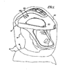
- Figure 1 is a perspective view of a helmet type personal protection system of this invention fitted over the head of a user;
- Figure 2 is a cross-sectional view of the helmet assembly
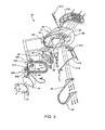
- Figure 3 is an exploded perspective view of the helmet assembly
- Figure 3A is a plan view of the front of the scroll housing
- Figure 3B is a plan view of the rear of the scroll housing
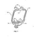
- Figure 4 is a perspective view of the head band
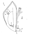
- Figure 5 is a side view of the helmet assembly with a toga and hood with face shield
- Figure 6 is a perspective view of the helmet assembly illustrating a positioning and supporting system including a mounting clip supporting the face shield via an aperture in the face shield;
- Figure 7 is a side view of the helmet assembly implementing a light assembly
- Figure 8 is a bottom view of the helmet assembly implementing the light assembly
- Figure 9 is a back view of the helmet assembly implementing the light assembly
- Figure 10 is a cross-sectional view of the helmet assembly along the line 10-10 shown in Figure 9 ;
- Figure 11 is a bottom view of the helmet assembly implementing the light assembly
- Figure 12 is a cross-sectional side view of the helmet assembly showing a printed circuit board disposed within the helmet assembly;
- Figure 13 is a front view of the helmet assembly
- Figure 14 is a side view of the helmet assembly showing a handle for adjusting the angle of the light assembly
- Figure 15 is a side view of the helmet assembly
- Figure 16 is a perspective back view of the helmet assembly along the line 16-16 shown in Figure 15 ;
- Figure 17 is a partial exploded view of the helmet assembly showing the components of an light adjustment mechanism for adjusting the angle of the light assembly;
- Figure 18 is a perspective view of the helmet assembly
- Figure 19 is a bottom view of the helmet assembly
- Figure 20 is an electrical block diagram illustrating the flow of electricity from a power supply to a motor and a light source
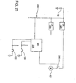
- Figure 21 is an electrical schematic diagram showing the relationship between electronic components disposed on the circuit board
- Figure 22 is an electrical block diagram of a communications system
- Figure 23 is a side view of the helmet assembly illustrating a microphone of the communications system
- Figure 24 is a front view of the helmet assembly illustrating the microphone and a speaker of the communications system
- Figure 25 is a side view of the helmet assembly illustrating the microphone and the speaker of the communications system
- Figure 26 is a block diagram of how, in some versions of this invention, a single power supply provides the energization current for the fan motor, the light source and the communications transceiver;
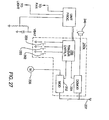
- Figure 27 is a block diagram of the components internal to a transceiver of this invention.
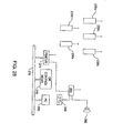
- Figure 28 is a diagrammatic illustration of how signals are exchanged between different communications units of this invention.
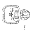
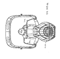
- Figure 29 is a perspective view of an alternative head unit of the personal protection system of this invention.
- Figure 30 is a front view of the head unit
- Figure 31 is a side view of the head unit
- Figure 32 is rear view of the head unit
- Figure 33 is a rear perspective view of the head unit
- Figure 34 is an exploded view of the head unit
- Figure 35 is a perspective view of the face frame
- Figure 36 is a plan view of one of the head straps
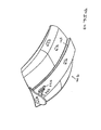
- Figure 37 is view of the outside of the rear nozzle assembly shell
- Figure 38 is a view of the inside of the rear assembly shell
- Figure 39 is a perspective view of the inside of the plate of the rear nozzle assembly.
- Figure 40 is a perspective view of the knob integral with the rear nozzle assembly
- Figure 41 is a perspective view of tip of the rear nozzle assembly
- Figure 42 is a view of the inside of the lower shell of the ventilation unit
- Figure 43 is a perspective view of the upper shell of the ventilation unit
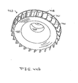
- Figure 44 is a perspective view of the ventilation unit fan
- Figure 44A is a perspective view of the underside of the fan.
- Figure 45 is a perspective view of the ventilation unit grill unit
- Figure 46 is a perspective view of the ventilation unit motor cover
- Figure 47 is a perspective view of the front nozzle assembly pedestal
- Figure 48 is a perspective view of the front nozzle assembly cap
- Figure 49 is a perspective view illustrating how the light is adjustably mounted to the head unit
- Figure 50 depicts how the flex circuit is attached to the front frame chin bar
- Figure 51 depicts how switches are mounted to the front frame chin bar
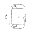
- Figure 52 is a plan view of the hood/toga transparent shield used with the head unit.
- Figure 53 is a block diagram of how the power supply, the fan, the transceiver and light generating source of the personal protection system of this invention are contained in a common housing.
- a personal protection system is generally shown at 10.
- the personal protection system 10 is adapted from the personal protection system 10 disclosed in United States Patent No. 6,481,019 to Diaz et al. and United States Provisional Patent Application No. 60/664,900 , both of which are hereby incorporated by reference.
- the personal protection system 10 of the present invention is implemented as a helmet assembly 12 mountable to the head 14 of a user, as shown in Figure 1 .
- the personal protection system 10 filters air between the head 14 and body 16 of a user, e.g., a medical professional, and an environment external to the user.
- the helmet assembly 12 distributes air about the head 14 of the user as will be described below. More specifically, the helmet assembly 12 distributes air toward both a front of the head 14, i.e., a face of the user, and a back of the head 14, i.e., a neck of the user.
- the helmet assembly 12 includes a shell 17 having an inner shell portion 18 facing the user and an outer shell portion 20 facing away from the user.
- the outer shell portion 20 is spaced apart from the inner shell portion 18 to define at least one air flow channel 26 between the inner and outer shell portions 18, 20.
- the present invention may include more than one discrete air flow channel 26.
- the illustrated embodiment includes a single unitary air flow channel 26 and the present invention will be described below in terms of this air flow channel 26.
- the shell 17 is preferably formed of acrylonitrile butadiene styrene (ABS), but may be formed, in alternative plastics.
- the helmet assembly 12 also includes a facial section 40 extending from the shell 17 to define a facial opening 42.
- the facial section 40 of the helmet assembly 12 is a chin bar 44.
- the chin bar 44 is flexible and is formed of plastic such as polypropylene. The flexibility of the chin bar 44 protects the wearer's face and absorbs impact when the user contacts an external object with the helmet assembly 12.
- the chin bar 44 also holds the hood 92 ( Figure 1 ) away from the face of the wearer
- the helmet assembly 12 includes a fan module 46 mounted in a cavity 38 in the shell 17
- Fan module 46 includes a fan 50 and a motor 52 mounted to a scroll housing 48.
- Fasteners M that extend through the shell 17 into threaded bores in the housing 48 to hold the module 46 in cavity 38 (housing bores not shown).
- a cover plate 47 is fixed to the shell 17 below cavity 38 to cover the fan module 46.
- a cushion 49 is disposed between the cover plate 47 and a base of the fan module 46. The cushion 49 absorbs the sound emitted by the fan motor 52. This reduces the amount of noise emitted by the system 10 of this invention.
- the scroll housing 48 may be formed of glass-filled polypropylene to reduce vibrations.
- the helmet assembly 12 further includes an intake grid 100 mounted to the outer shell portion 20.
- the intake grid 100 includes a top surface spaced from the outer shell portion 20 of the helmet assembly 12.
- the intake grid 100 is contoured to the outer shell portion 20 between the front and rear of the shell 17. Air is drawn into the scroll housing 48 through the intake grid 100 by the fan 50.
- FIG. 3 Also shown in Figure 3 are various fasteners and washers, not identified, that secure the components forming helmet assembly 12 together.
- the motor 52 rotates the fan 50 to draw air into the air inlet 64 of the scroll housing 48 through the intake grid 100.
- the air is discharged through two spaced openings in the scroll housing 48.
- a first opening 51 seen in Figure 3A is in the front of the scroll housing 48.
- the air discharged from opening 51 flows directly into the opening 25 into air flow channel 26.
- From channel 26, the air is discharged from an outlet opening 35 between the inner and outer shell portions 18 and 20, respectively, in the front of the shell 17
- the second opening, opening 53 is located in the rear of the scroll housing 48, best seen in Figure 3B .
- the air discharged from opening 53 flows into a manifold mounted to the rear of the scroll housing 48. From the manifold, the air is discharged from two downwardly directed nozzles.
- the manifold and nozzles are formed as a single unit, S in Figure 3 . When the system 10 is worn, the nozzle discharge ports are positioned adjacent the back of the neck of the wearer.
- the air flow channel 26 defined between the inner and outer shell portions 18, 20 terminates at the front section 34 with the front air exits. More specifically, the inner and outer shell portions 18, 20 converge toward the front section 34 to define the front air exits.
- the front air exits may have an air deflector defined between the outer shell portion 20 and the inner shell portion 18 wherein the outer shell portion 20 angles toward the inner shell portion 18 at the front air exits for proper deflection of air toward the front of the head 14 of the user.
- Such an air deflector is best shown in U.S. Patent No. 6,481,019 et al., which, again, is hereby incorporated by reference.
- Air flow channel 26 diverges upon approaching the front air exits. The convergence and divergence of the air flow channel 26 maintains a balanced flow of air about the user's head 14. Ultimately, this also has the effect of minimizing or even completely eliminating noise within the helmet assembly 12 due to the air flow.
- an adjustable head band 128 assists in minimizing the strain on the head 14 and the neck of the user. Strain and torque on the head 14 and neck of the user is minimized by maintaining the weight of the fan 50 and motor 52 over the neck of the user even upon adjustment of the helmet assembly 12 to fit various sized heads 14.
- the head band 128 includes a rear support 130 that rigidly extends from the shell 17. It is understood that the rear support 130 can be a separate part that is connected to the helmet assembly 12 or can be an integral part of the helmet assembly 12.
- the rear support 130 includes first and second rigid connectors 132 that connect the rear support 130 to the rear section 36. In the preferred embodiment, the rear support 130 is connected to and extends from the rear section 36 of the inner shell portion 18 and will be described below in terms of the inner shell portion 18. However, it is to be understood that the rear support 130 can connect to and extend from any portion of the shell 17.
- An adjustment segment 134 having a first side 136 and a second side 138 is also part of head band 128.
- the rear support 130 preferably includes the adjustment segment 134.
- the adjustment segment 134 is integral to, or the same part as, the rear support 130.
- the adjustment segment 134 is a discrete component that is simply mounted to the rear support 130. In either situation, the adjustment segment 134 defines apertures 140 for receiving a first end 144 and a second end 146 of a strap 142 flexibly connected to and extending from the front section 34 of the inner shell portion 18. The first end 144 is disposed within the first side 136 of the adjustment segment 134, and the second end 146 is disposed within the second side 138 of the adjustment segment 134.
- the first end 144 is movably disposed within the first side 136 of the adjustment segment 134, and preferably the second end 146 is movably disposed within the second side 138 of the adjustment segment 134.
- the first end 144 may be movably disposed within the first side 136 of the adjustment segment 134 and the second end 146 may be fixedly disposed within the second side 138 of the adjustment segment 134.
- the first end 144 may be fixedly disposed within the first side 136 of the adjustment segment 134 and the second end 146 may be movably disposed within the second side 138 of the adjustment segment 134.
- the strap 142 further includes a frontal portion 148 disposed between its first and second ends 144, 146 and opposite the adjustment segment 134 of the rear support 130. At least one support arm 150 flexibly extends from the frontal portion 148 of the strap 142 to flexibly connect the strap 142 to the front section 34 of the inner shell portion 18. These support arms 150 act as hinges for the head 14 support assembly. Preferably, there are two support arms 150 that extend from the frontal portion 148 of the strap 142. In such a case, the two supports arms are connected to the front section 34 of the inner shell portion 18 and to the frontal portion 148 of the strap 142 equidistant from one another. A gap 152 exists between the frontal portion 148 of the strap 142 and the front section 34 of the inner shell portion 18.
- the personal protection system 10 includes a toga 88 having a body portion 90 for covering substantially all of the body 16.
- Toga 92 includes a hood 92 for covering the head and helmet assembly 12.
- the body portion 90 can extend downward to cover any portion of the body 16 of the user. For instance, the body portion 90 can extend downward to the waist of the user, or to the ankles of the user.
- the hood 92 includes a filter element 94 to filter air between the user and the external environment.
- the facial section 40 of the helmet assembly 12, introduced above, also operates to maintain the hood 92 away from the head 14 of the user.
- the intake grid 100 spaces the filter medium 94 out away from the outer shell portion 20 and the fan 50.
- a hood unit may be offered as a covering separate from the complete toga. This type of hood unit is used when there is only a need to provide a barrier around the head of the wearer.
- a transparent face shield 96 permits the user to view through the hood 92.
- the face shield 96 may include anti-reflective and/or anti-refractive coatings to enhance vision through the face shield 96.
- the face shield 96 is mounted to the hood 92 such that the face shield 96 covers the facial section 40 and the facial opening 42 of the helmet assembly 12 once the user dresses into the personal protection system 10.
- the face shield 96 is sewn into the hood 92.
- the facial opening 42 of the helmet assembly 12 receives the face shield 96.
- facial section 40 of the helmet assembly 12 includes a hook-and-loop fastener to further facilitate attachment of the face shield 96 to the facial section 40 for covering the facial opening 42.
- the personal protection system 10 includes a light assembly 200.
- the light assembly 200 is disposed within the hood 92 behind the face shield 96 to emit a beam of light that projects outside of the hood 92. Since the light assembly is disposed within the hood 92, there is no need to meticulously clean the light assembly to keep it to the sterile conditions of a surgical room.
- Light assembly 200 includes a light generating unit, light source 201, disposed adjacent to a lens (not shown).
- the light source is preferably one or more light-emitting diodes (LEDs).
- the LED emits white light. In one version of the invention, light is emitted at a color temperature of 5500°K. Light in this spectrum is equivalent to daylight and provides true tissue color rendition.
- a light housing 202 supports and surrounds the LEDs and the lens.
- One suitable light assembly 200 is the PeriLux LED, manufactured by PeriOptix, Inc. of Mission Viejo, California.
- the light source may alternatively be an incandescent light bulb or other suitable sources as are well known in the art.
- One possible alternative is the use of a light source mounted somewhere on the user and fiber-optic cables to carry the light to the light housing.
- the lens is circular in shape.
- the longitudinal position of the lens relative to the light source 201 is selectively set. This allows the user to selectively focus/diffuse the beam of light emitted from the light assembly 200.
- Many lens displacement assemblies include a rotating collar. Rotating the collar in a first direction cause movement of the lens to focus light is concentrated in a small area. Rotation of the collar in the opposite direction results in movement of the lens so that the emitted light is diffused about a large area. This rotation of the collar may be done manually or with a focusing servo motor. Control of the electric servo motor is explained in greater detail below.
- Light assembly 200 includes a light angle adjustment mechanism 204.
- Mechanism 204 allows the user to change the direction of the beam of light so it can be directed to a specific location.
- the light housing 202 is pivotally mounted to two parallel legs 210 (one shown in Figure 7 ).
- Legs 210 are integrally formed with and extend downwardly from a rigid block 209.
- Block 209 is attached to the front outer surface of the strap 142.
- a pin 211 that extends through the ends of the legs 210 pivotally holds the light housing 202 to the legs.
- a semi-rigid cable 216 regulates the pivotal movement of the light housing 202.
- the cable 216 is contained in a sheath (not identified).
- a cable clamp AW and rivet P cooperate to hold the forward end of the sheath to the exposed face of the inner shell portion 18.
- the rear end of the sheath, with the cable 216 contained therein, extends through an opening in the shell 17 into the void space between the inner and outer shell portions 18 and 20, respectively.
- a ring clamp AZ is disposed over the front of the housing, immediately proximal to the front face.
- the opposed ends of the ring clamp (one shown as element 206 in Figure 8 ) extend upwardly towards shell 17.
- An elongated screw 217 ( Figure 3 ) extends between ring clamp ends 206 to compression secure the ring clamp AZ to the light housing 202.
- the front end of the cable 216 is wrapped around the exposed section of screw BA between the ring clamp end sections 206.
- Lever arm 214 is connected by a pin (not identified) to an adjustment knob 212 located outside of the shell 17 ( Figure 9 ).
- the pin extends through the shell outer portion.
- the proximal end, the rear end of the cable 216 is attached to the end of the lever arm 214 distal from the pin.
- the rotation of the knob and lever arm subassembly thus results in the extension/retraction of the cable.
- the cable movement pivots the light housing 202 around the axis defined by pin 211.
- the light housing 202 and, more particularly, the light source 201 are positioned directly under the front air outlet opening 35. By positioning as such, the air discharged from opening 35 blows the warm air surrounding the light assembly 200 away from the light assembly. This reduces the build up of heated air adjacent the light assembly. Instead, the heated air is exhausted out of the hood 92. The removal of this heated air lessens the extent to which the heat generated by the light assembly excessively warms the wearer of the personal protection system 10.
- Still another feature of this construction of the invention is that it minimizes the extent to which the temperature of the light assembly 200 itself rises due to the heat emitted by source 201.
- the source 201 By maintaining the light source 201 at a relatively low temperature, the source itself is able to function as a relatively efficient light emitter. (The light-emitting efficiency of LED type light source drops with an increase in the temperature of the LED.)
- Power supply 70 energizes both the motor and the light source.
- power supply 70 may be divided into a pair of power supplies, with each power supply individually powering the motor 52 or the light assembly 200.
- Power supply 70 is preferably at least one cell (i.e., battery).
- the at least one cell may be rechargeable.
- non-rechargeable (i.e., disposable) cells may also be used.
- power supply 70 provides a 6 VDC power signal.
- other voltages may alternatively be implemented.
- the first power supply 70 is preferably mounted to the body 16 of the user as shown in Figure 5 . By mounting the first power supply 70 outside of the toga 88, it can be easily replaced (i.e., switched out) during a medical/surgical procedure. In some versions of the invention, power supply 70 is located where it is accessible through the toga. Alternatively, the first power supply 70 may be disposed within, i.e., integrated into, the helmet assembly 12.
- the personal protection system 10 further includes a fan control circuit 224 for regulating the actuation of the fan motor 52.
- a voltage regulator 220 applies a constant voltage signal to control circuit 224 for energizing the control circuit.
- Voltage regulator 220 regulates the 6 VDC electric current received from the power supply. In one version of the invention, voltage regulator 220 provides a 3.3 VDC electric current which energizes the fan control circuit 224.
- a light control circuit selectively applies an energization signal to the light source 201 to control both the on/off state of the light source and the intensity of the light emitted by the source.
- the light control circuit is shown as current regulator 230.
- the current regulator 230 receives a constant voltage energization signal from a voltage regulator 222.
- voltage regulator 222 which is connected to power supply 70, supplies a 3.6 VDC signal to current regulator 230.
- a single voltage regulator provides a common constant voltage to both the fan control circuit and the light control circuit. In some versions of the invention, there may not even be a need to provide a voltage regulated energization signal to either the fan control circuit or the light control circuit. Thus, in some versions of the invention, either one or both of the fan and light control circuits are powered directly from the power supply 70.
- the fan control circuit 224 is electrically connected to the fan motor voltage regulator 220 and the motor 52.
- the fan control circuit 224 receives electric current from the fan motor voltage regulator 220 and conditions the electric current to control the speed of the motor 52 and the fan 50.
- the fan control circuit 224 provides implements pulse-width modulation (PWM) for controlling the speed of the motor 52 and the fan 50.
- PWM pulse-width modulation
- the fan control circuit 224 includes a microcontroller 118 and a power transistor 226.
- the microcontroller 118 includes a plurality of inputs and outputs.
- Two switches 120 and 122 are pushbuttons are electrically connected to individual inputs of the microcontroller 118. (Not identified are the pull up resistors associated with the switches.)
- the user presses the pushbuttons to adjust the desired speed of the fan 50 (and the consequential air flow).
- the switches are in the form of pushbuttons mounted to the side of the helmet assembly 12 and are easily operable by the user through the hood 92.
- At least one output of the microcontroller 118 is electrically connected to the power transistor 226 to selectively turn on and turn off the transistor based on the desired speed of the fan 50. More specifically, the energization signal applied through the transistor is a PWM signal having a constant frequency and a variable on duty cycle that is directly proportional to the desired fan speed.
- Power transistor 226 is in one version of the invention, actually a pair of power MOSFETs, the individual MOSFETs not shown.
- a primary MOSFET is a P-channel type and a secondary MOSFET is an N-channel type.
- the drain of the primary MOSFET is tied to the positive input of the power supply.
- the source of the primary MOSFET is tied to fan motor 52.
- the gate of the primary MOSFET is tied to the positive terminal of the battery through a resistor.
- the drain of the secondary MOSFET is also tied to the gate of the primary MOSFET.
- the source of the secondary MOSFET is tied to ground.
- the gate of the secondary MOSFET is connected to a control line from the microcontroller 118.
- the signal present at the drain of the secondary MOSFET gates the primary MOSFET.
- the IRF7307TR Power MOSFET manufactured by International Rectifier, headquartered in El Segundo, California is a single package that contains both the P- and N-channel MOSFETs that collectively form power transistor 226.
- power transistor 226 are possible.
- Microcontroller 118 is preferably is a Model ATmega8 manufactured by Atmel Corporation, headquartered in San Jose, California. The ATmega8 includes built-in PWM support. Other suitable microcontrollers 118 or microprocessors are evident to those skilled in the art. The microcontroller 118 may also be used for functions separate from controlling the speed of the fan 50, as is described in greater detail below.
- the current through motor 52 is used as feedback signal to establish the PWM rate.
- a resistor (not illustrated) is tied between the motor 52 and ground. The voltage across the resistor is applied to microcontroller 118 so as to serve as an indication on the motor speed. Motor speed is adjusted by varying the percent on duty cycle of the pulse per fixed total period (on and off) of the pulse.
- Microcontroller 118 may also be electrically connected to the focusing servo motor and the light angle servo motor. This eliminates the need to hand adjust the light.
- the invention provides an audible indication of when the fan is at the minimum and a maximum air flow rates.
- This indication is provided by momentarily resetting the frequency of the PWM signal applied to the motor. This in turn, causes the motor to be actuated at a rate that causes is shaft to rotate in a manner that causes sound detectable by the human ear to be emitted.
- This sound provides an audible indication of the minimum and the maximum volume of air to the user. That is, the present invention provides the user with an audible 'ping' upon reaching the minimum and maximum volumes of air flowing into the helmet assembly 12.
- This ping is also provided each time the control circuit 224, in response to the depression of one of the control buttons, raises or lowers the speed of the fan motor 52.
- the controller is configured to actuate the motor so two closely spaced apart in time pings are emitted at the same frequency. This provides the user notice the maximum or minimum motor speed setting has been reached.
- the audible ping is provided by, for a brief period, for example between 0.1 and 0.2 seconds, running the fan motor at a frequency at which the motor generates an audible sound.
- the constant frequency of the energization signal applied by the control circuit 224 is 30.3 kHz.
- the energization pulses are applied to the motor at a frequency of between 261 to 523 Hz at a 50% duty cycle.
- the speed of the motor drops appreciably. This causes the motor 52 to emit a tone detectable by the human ear
- the frequency at which the motor is actuated in order to generate the ping varies with new speed range the motor is being set to operate at.
- the control circuit 224 prior to each time the control circuit 224 increases the on duty cycle of the motor energization signal in order to increase motor speed, the control circuit first applies a high frequency ping-generating energization signal. This results in a relative high frequency ping signal being generated.
- the control circuit Prior to the control circuit 224 decreasing the on duty cycle for the energization signal in order to decrease motor speed, the control circuit applies a lower frequency ping-generating energization signal. This results in the emission of a lower frequency ping from the motor 52.
- the surgical personnel not only receive an audible indication the fan speed is being reset, they receive an indication regarding if the speed is being lowered or increased.
- the frequency at which the motor is selectively actuated may otherwise be within the acceptable range of unaided human hearing (30 Hz to 20 kHz) so long as it provides the audible indication.
- the frequency of the activation rate causes various components of the motor 52 of the fan module 46 to vibrate at the frequency thereby generating the audible indication.
- the fan control circuit 224 includes a potentiometer, also commonly referred to as a variable resistor or varistor, to control the speed of the motor 52 and fan 50, instead of utilizing PWM. Additional implementations for varying the speed of the motor 52 and fan 50 are known to those skilled in the art and may be alternatively utilized.
- a printed circuit board 228 (PCB) is disposed within the helmet assembly 12.
- the PCB 228 supports the voltage regulators 220, 222, the microcontroller 118, and associated electronic devices.
- the PCB 228 includes conductive tracks to electrically connect items mounted on the PCB 228, as is well known to those skilled in the art.
- the personal protection system 10 also includes a light current regulator 230 for providing a constant current, regardless of voltage, to the light source. By keeping the current constant, the light source provides a steady illumination that does not degrade as the cells of the first power supply 70 drain and lose voltage.
- the light current regulator 230 is preferably integrated with the light assembly 200 within the light housing. However, the light current regulator 230 may be disposed on the PCB 228.
- the personal protection system 10 also includes a low power detection circuit for alerting the user when the cells of power supply 70 are running low.
- a voltage divider circuit 232 comprising a pair of resistors is electrically connected to the first power supply 70. The signal present at the junction of the resistors is applied as an input signal to microcontroller 118.
- An enunciator 234 is electrically connected to one of the outputs of the microcontroller 118.
- the enunciator 234 may be an indicating LED, preferably mounted within the helmet assembly 12 and within the field of view of the user.
- the enunciator 234 may also be a loudspeaker for producing an audible signal that is hearable by the user, or a combination of the loudspeaker and LED.
- the enunciator 234 may be substituted with selectively activating and deactivating the power transistor 226 to vibrate the fan and generate an audible signal, as described above.
- personal protection system 10 also includes a communications unit 236.
- the communications unit 236 provides wireless communication between other communications units 236.
- the other communication units may be integrated with other personal protection systems 10 or embodied as one or more stand-alone units.
- the communications units 236 allow for convenient voice communications between the users of the personal protection systems 10.
- the communications unit 236 includes a microphone 238, a speaker 240, and a transceiver 242. Communications unit 236 also includes a second power supply 244.
- the second power supply 244 powers transceiver 242.
- Second power supply 244 is preferably at least one cell.
- the at least one cell is preferably rechargeable; however, non-rechargeable cells may also be used.
- the at least one cell may be a single cell or a plurality of cells connected together.
- the transceiver 242 and second power supply 244 are often packaged together and mountable on the body 16 of the user.
- the transceiver 242 is electrically connected to the first power supply 70, such that the user would not have to carry multiple power supplies.
- a third voltage regulator 241 provides a third constant voltage signal to the transceiver 242. This third voltage is different from the regulated voltages provided to the fan control circuit 224 and the light control circuit (current regulator 230).
- Transceiver 242 may also be alternatively disposed within the helmet assembly 12.
- Microphone 238 converts speech into electrical signals.
- the signals produced by the microphone 238 are applied to the transceiver 242.
- Transceiver 242 is preferably a radio frequency (RF) transceiver 242 capable of transmitting and receiving RF signals.
- the transceiver 242 converts the electrical signal into an RF signal and transmits the RF signal.
- the transmitted RF signal may then be received by the transceivers 242 of the other communication units.
- the transceiver 242 converts the received RF signal into an electrical signal.
- the speaker 240 is electrically connected to the transceiver 242 and receives the electrical signal from the transceiver 242.
- the speaker 240 decodes the electrical signal into an audio wave which can be heard by the user.
- Microphone 238 is attached to the chin bar 44 of the helmet assembly 12.
- a cable 239 (shown in phantom) over which the signals produced by the microphone is similarly disposed in the chin bar 44.
- the microphone may be mounted to other locations on the helmet.
- speaker 240 is an earpiece.
- the earpiece includes a hook shaped to be worn on the ear of the user.
- a bud with the actual sound generating transducer is attached to the hook.
- the bud is shaped to be positioned adjacent or in the ear canal of the user.
- the audio signal cable that supply signals to the bud are mounted to the helmet.
- the front end of the cable is however, not mounted to the helmet. This provides a degree of flexibility between the earpiece and the helmet shell 17. This flexibility accommodates for differences in body size of individual users. This flexibility also allows the user to move his/her head while using the personal protection system 10 of the invention while the earpiece remains in place. Also, multiple mounting assemblies are provided in the helmet. This allows the earpiece to be mounted for insertion in either ear of the user of the system 10.
- Transceivers 242 in one version of the invention, operate in the 900 MHz band.
- the individual transceivers exchange digital, spread spectrum RF signals.
- the communications units 236 preferably operate in full duplex, i.e., the transceivers 242 can transmit and receive RF signals at the same time.
- a suitable transceiver 242 is the STx 1000 manufactured by Eartec of Narragansett, Rhode Island. Coachcomm of Auburn, Alabama also markets an appropriate transceiver system. Each of these systems allows three or more individuals to simultaneously use the surgical protect system 10 of this invention and communicate in full duplex mode with each other using the transceivers. There is no need to depress a push-to-talk switch in order for any individual to communicate with another individual.
- this protection system 10 allows a group of individuals (three or more) to engage in conversation with each other as if in normal group conversation, without having to raise their voices in order to overcome the sound attenuating of the protective hoods 92 and the noise generated by the fan 50 and motor 52.
- Transceiver 242a includes a modulator 252 for converting audio signals received from the microphone 238 into RF signals.
- the RF signals generated by the modulator 252 are broadcast over communications unit antenna 237.
- the transceiver demodulator 254 Also connected to antenna 237 is the transceiver demodulator 254.
- the demodulator 254 converts the received RF signals into audio signals that can be used to actuate the speaker 240.
- Actuation of the modulator 252 and demodulator 254 is controlled by a transceiver controller 256 also part of transceiver 242a.
- This transceiver controller 256 could be a conventional digital microprocessor, a PLA or a DSP.
- Transceiver controller 256 regulates the actuation of the modulator 252 and demodulator 254 in part based on the state of three user actuated switches 258, 260 and 262.
- An individual wearing system 10 of this invention could actuate one switch, for example switch 258, in order to effectively "turn off" the demodulator. 254.
- An individual takes this step if he/she does not want to receive the transmissions broadcast by others employing the communications units.
- the transmitter controller could respond by deactivating the demodulator 254.
- the transceiver controller 256 in response to the user wanting speaker 240 deactivated, turns on a FET that causes the audio output signal generated by the demodulator 254 to go to ground (FET not illustrated).
- Transceiver controller 256 also selectively deactivates the output of RF signals by the modulator 252.
- the individual using system 10 may want the modulator 252 to temporarily stop broadcasting RF signals with embedded audio signals if he/she wants to conduct a conversation with a nearby individual that is not for broadcast.
- Switch 260 is actuated to regulate the selective broadcast of the RF modulated audio signals.
- the transceiver controller 256 temporarily stops actuation of the modulator 252. Alternatively, by switching a FET (not illustrated) the transceiver controller 256 selectively blocks the forwarding of audio signals from the microphone to the modulator 252.
- the transceiver controller 256 also regulates the modulator 252 to control which group or groups of other communication units 236 are able to receive signals emitted by the transceiver 242a.
- the transmitter controller 256 regulates the codes used to establish the modulation of the output signals and the demodulation of the input signals.
- transceiver controller 256 generates the code that establishes the frequency hoping pattern of the carrier frequency.
- Switch 262 is the control member that is actuated to establish which group or group of communications units are able to exchange and/or receive signals.
- FIG. 28 The utility of the protection system of this invention's ability to selective exchange signals is now explained by reference to Figure 28 .
- communications unit 236d is one unit that has this selective transmission/reception capability.
- the associated transmitter controller 256 configures the transceiver 242a of communication unit 236d so that the broadcast audio signals can be received by all the remaining units 236a, 236b, 236c and 236e or just by unit 236e. This allows a surgeon to have some privacy to communication with another individual wearing the system 10. Alternatively, this allows a surgical assistant to communicate with another individual without disturbing the surgeon.
- a receiver 264 is also shown.
- the receiver is capable of receiving the signals broadcast by one or more the communication units 236a-236e.
- the audio signals broadcast by the receiver 264 can be broadcast through a loudspeaker 263. This may be desirable in a teaching setting. Alternatively, the audio signals may be stored with the aid of a recorder 265. Again, by selective modulation of the broadcast signals, the ability of the receiver to demodulate the signals broadcast by any particular transceiver 242a is selectively regulated.
- a unit processor 272 is connected to the transceiver controller 256.
- Digital signals extracted from the received RF signals by the demodulator 254 are forwarded to the transceiver controller 256.
- Modulator 252 is able to embed digital signals received from the transceiver controller 256 into the broadcast RF signals.
- the transceiver controller 256 functions as a intermediate processor for transmitting digital signals received by the unit processor 272 and forwarding digital signals used by the unit processor.
- transceiver controller 256 and unit processor 272 are a single unit.
- Transceiver 259 is connected to a communications bus 266 in the operating room.
- Other units connected to the bus include the below-discussed operating room control head 261 and equipment such as a personal computer 268.
- One such operating room control head 261 is sold by the Applicants' Assignee under the trademark SIDNE. This arrangement allows the transceiver 242a to serve as the unit through which other components of the surgical protection system 10 exchange signals with remote devices.
- the operating room control head is shown as receiving audio signals from the static receiver 264.
- transceivers 264 and 259 are a single unit.
- the surgeon speaks the command "Focus Light".
- the audio signal representative of these words is transmitted by transceiver 242a to the operating room control head.
- the operating room control head processes the audio signals to decode the command.
- the operating room control head through transceiver 259 generates a command data packet to the transceiver 242a.
- the transceiver 242a strips out the command message and forwards it to the unit processor 272.
- Unit processor 272 upon receipt of the command, generates appropriate control signals to cause the actuation of the servo motor employed to displace the lens integral with the light assembly 200.
- the speed of the fan motor 52 is similarly regulated by the integrated system of this invention.
- Communication unit 236a can also provides voice actuated control of the other equipment in the operating room such as the surgical instruments and the operating room environmental settings (HVAC and light). More specifically, the spoken commands entered through microphone 238 are transmitted by transceiver 242a and receiver 264 to the operating room control head 261. The operating room control head then generates the appropriate instruction packets that are output on bus 266 to the appropriate device that is to act on the instructions.
- voice actuated control of the other equipment in the operating room such as the surgical instruments and the operating room environmental settings (HVAC and light). More specifically, the spoken commands entered through microphone 238 are transmitted by transceiver 242a and receiver 264 to the operating room control head 261. The operating room control head then generates the appropriate instruction packets that are output on bus 266 to the appropriate device that is to act on the instructions.
- HVAC and light operating room environmental settings
- the integrated construction of the system of this invention also allows the personal protection system 10 to report back information regarding its own operating state.
- the signal present at the junction of the two resistors forming voltage divider 232 is shown as being applied to unit processor 272.
- the unit processor 272 In the event the signal present at this point falls to a level at which indicates the charge stored in power supply 70 is becoming low, the unit processor 272 generates a data packet with these data.
- the data packet is forwarded to the transceiver controller 256 so it is broadcast by the transceiver 242a.
- the data packet is received by transceiver 259. This packet is forwarded to the personal computer 268. This provides personnel in the operating room with notice that the particular power supply 70 worn by a specific individual is close to being discharged and should be replaced.
- Figures 29 through 34 illustrate an alternative support structure for supporting hood 92 around the head and upper body of the wearer.
- This particular support structure is a head unit 270.
- Head unit 270 includes a head band 272 to which a ventilation unit 274 and light 276 ( Figure 49 ) are adjustably mounted.
- the air forced through the ventilation unit 274 is discharged through front and rear nozzle assemblies 280 and 282, respectively.
- the adjustability of the ventilation unit 274 relative to the head band allows the components forming the unit, primarily the ventilation fan 278, to be positioned relative to the body of the wearer where the physical strain the unit imposes on the wearer is minimized.
- head unit 270 includes a face frame 286 formed of plastic that has some flexibility.
- face frame 286 is formed from polypropylene or Nylon.
- Face frame 286, best seen in Figure 35 is shaped to have a forehead band 288 that has a curvature designed to allow the bar to fit against the forehead of the individual. Not shown are padding that may be secured to the inner surface of the forehead band 288.
- face frame 286 Extending downwardly from the opposed ends of forehead band 288, face frame 286 has downwardly extending support posts 290.
- a chin bar 292 also part of face frame 286 extends between the opposed bottom ends of support posts 290.
- Chin bar 292 has a curved shape such that forward portion of the guard between the posts 290 extends forward of the posts.
- Support strap 294 is in the form of a generally rectangular strip and extends upwardly from the center of the forehead band 288. As discussed below, support strap 294 is the member from which the ventilation unit 274, light 276 and front nozzle assembly 280 are suspended.
- a mounting pin 296 extends outwardly from each of the face frame support posts 290.
- Each mounting pin 296 has a stem (not identified) that extends outwardly from the outer surface of the associated support post 290.
- Each mounting pin 296 also has a wide diameter head 298 that forms the free end of the pin. Mounting pins 296 support and secure the transparent shield integral with the hood.
- a head strap 302 extends rearwardly from each end of the face frame forehead band 288. Collectively, the forehead band 288 and head straps 302 form the head band 272. Head straps 302 are formed from very flexible plastic such as Nylon 66. Each head strap 302, as seen in Figure 36 , includes a base 306 that has a relatively wide width. Base 306 is seated against the inner surface of the associated end of the forehead band 288. Two openings 308 extend through each strap base 306. Openings 308 accommodate fasteners (not illustrated,) that hold the head strap 304 to the face frame 286. In the illustrated versions of the invention, a counterbore (not identified) extends around each opening 308.
- a leg 310 extends downwardly from the each head strap base 306. Each leg 310 has a width less than that of base 306 from which the leg extends.
- Each head strap 302 has a rack 312 that extends from the free end of the leg 310.
- the racks have a set of teeth (not identified) that extend laterally away from the longitudinal axis of the rack.
- Figure 36 illustrates the head strap 302 for the left side of head unit 270. This head strap 302 is formed so that the rack teeth project downwardly.
- the head strap 302 for the right side of the head unit 270 is formed so that the teeth project upwardly.
- a toe 314 projects perpendicularly away from the free end of each rack 312. Each toe 314 is directed in the same direction in which the associated rack teeth are directed.
- Rear nozzle assembly 282 both directs the output flow from the fan 278 down the neck of the wearer and holds head straps 302 together.
- Rear nozzle assembly 282 includes a shell 320 and a tip 318 that rotates around the longitudinal axis of the shell.
- Shell 320 is formed from a single piece of plastic and has a three-sided trunk 322 from which two wings 324 extend. More particularly, the trunk 322 is formed to have a back wall 326 that curves into two opposed side walls 328. Shell 320 is further formed so that the opposed side walls 328 are inwardly tapered. Consequently, shell 320 is wider at the top than at the bottom.
- the shell 320 is further formed to have two spaced apart ribs 330 and 332 that extend laterally across the inner surface of the shell, from side wall to side wall. Rib 330 is located around the open end of the shell 320. Rib 332 is parallel to and located below rib 330.
- a plate 334 extends from the inner surfaces of back wall 326 and side walls 328. Plate 334 extends to and does not project beyond the inner edges of the side walls 328. An opening 336 extends through the plate 334. Opening 336 is centered along an axis that extends longitudinally through the void space defined by the shell back wall 326 and side walls 328.
- a rigid tubular sleeve 340 extends inwardly from the shell back wall 326 so to project into the void space between the back wall and side walls 328.
- Sleeve 340 extends from an opening 342 in the back wall 326.
- the back wall 326 is further formed to have an annular ring 344 concentric from and radially spaced away from opening 342 that projects from the wall outer surface. Ring 344 is formed with spaced apart teeth 346 that extend inwardly to opening 342.
- Each shell wing 324 extends from a separate one of the base side walls 328.
- the wings 324 are basically three wall structures that are arranged so that the open faces thereof extend forwardly, toward face frame 286.
- Plural spaced apart reinforcing webs 350 extend through the void spaces defined by each wing 324 and the trunk side wall 328 from which the wing extends. Webs 350 extend laterally, that is perpendicular to the top-to-bottom longitudinal axis through the shell 320.
- Plate 352 now described by reference to Figure 39 , has a panel section 354 with a generally concavo-convex profile.
- the panel section 354 is further formed to have side edges (not identified) that are inwardly tapered.
- Panel section 354 is further formed so that the opposed top and bottom side edges are outwardly bowed.
- the panel section 354 is also shaped to have curved corners.
- plate 352 Extending outwardly from the inner surface of the panel section 354, the surface seen in Figure 39 , plate 352 is shaped to have two four sided reinforcing frames 356.
- Each reinforcing frame 356 extends outwardly from the inner surface of panel section 354.
- Each frame 356 has two parallel and spaced apart top and bottom ribs 358.
- An outer rib 360 located along the adjacent side edge of the panel section 354 extends between ribs 358 at one end of each frame.
- An inner rib 362, that is curved toward the side, extends between each of the ribs at the opposed inner end of each frame 356.
- a hole 364 extends through the center of panel section 354.
- the panel section 354 is formed with an annular rib 366 around the hole 364.
- the plate 352 is further shaped so that the frame inner ribs 362 have a center of curvature that is concentric with hole 364.
- a foot 368 projects outwardly from the bottom of panel section 354.
- Foot 368 has a planar base 369 that forms the bottommost structural component of the plate 352.
- Steps 370 extend from the opposed ends of foot 369 to the adjacent sections of the panel section bottom edge.
- Short lips 372 extend from each step 370 a short distance along the adjacent section of the panel section bottom edge.
- a reinforcing web 374 extends along the inner surface of the panel section 354.
- Web 374 extends between the opposed free ends of lips 372.
- the web 374 is parallel with and spaced apart from the two linearly aligned bottom ribs 358 of the reinforcing frames 356.
- a slot 359 is defined between the lowermost ribs 356 and web 374.
- the plate 352 also has a three sided collar 378 that is integral with and extends a short distance above the panel section 354.
- Collar 378 has a front wall 380.
- Two side walls 382 curve inwardly from the opposed ends of the front wall 380.
- Formed integrally with the collar are two parallel ribs 384 and 386.
- Rib 384 extends inwardly across the coplanar top edges of the collar front wall 380 and side walls 382. Rib 386 is located below and is spaced from rib 384.
- a lip 387 extends from each collar outwardly along the panel section top edge.
- the lips 387 project away from the inner surface of the panel section 354.
- a web 390 extends outwardly from the inner surface of the panel section 354 between the ends of the opposed lips 387.
- the web 390 is parallel to and located above the opposed, linearly aligned top ribs 378 of the reinforcing frames 356.
- a slot 392 is defined by the top located ribs 356 and web 390.
- Plate 352 is further formed to have a support arch 394.
- the arch 394 which has a generally circular shape, extends upwardly from top edge of panel section 354. While cross sectional slices through the arch are of constant diameter, the arch does not lie flat.
- the arch 394 is angled toward the center. This profile approximately matches the general contour at the back of the skull. More particularly, the opposed terminuses of arch 394 are each located between one end of collar 378 and the adjacent panel side edge. As discussed below, arch 394 flexibly supports the ventilation unit 274 above the head of the wearer.
- a knob 396 also part of the rear nozzle assembly 282, is mounted to the exposed back surface of the shell 320.
- the knob 396 seen best in Figure 40 , includes a cylindrical shaft 398. Arcuately spaced apart teeth 402 extend radially outwardly along the shaft 398.
- the knob shaft 398 is further formed to have a bore 399 that is open from the free end of the shaft. In one version of the invention, bore 399 extends through a sleeve 401 constrict with and located in shaft 398.
- the knob 396 also has a head 404 disposed over one end of the shaft 398.
- ring 406 Internal to the head 404 is ring 406 that extends around the portion of the shaft disposed in the head. Ring 406 is concentric with and spaced radially outwardly from shaft 398.
- the ring 406 is formed with two diametrically opposed flexible tabs 408 (one shown). Each tab 408 has a single rib 410 that extends longitudinally along the outer surface of the tab.
- the rear nozzle assembly 280 is constructed so that the knob shaft 398 seats in and extends through shell sleeve 340. The free end of the shaft 398 seats against the annular space about the reinforcing rib 366 formed in plate 352.
- a threaded fastener (not illustrated) extends through plate hole 364 and into bore 399 integral with knob 396. This fastener holds the panel 352 to the shell 320.
- head strap racks 312 seat in the slots between shell 320 and panel 352. This is seen best in Figure 30 ; here it is understood the left-right sides of head unit being inverted. Specifically, the rack 312 integral with the right side head strap 302 seats in slot 359. The rack 312 the forms part of the left side head strap seats in slot 392. The rack teeth engage knob teeth 402.
- Rear nozzle tip 318 includes a tubular base 412.
- a lip 414 extends annularly around the open end of base 412 and away from the outer surface of base. Projecting upwardly from lip 414, nozzle tip 318 has four equangularly spaced apart mounting tabs 416. Each tab 416 has a head 418 with a tapered outer surface. When the rear nozzle assembly 282 is put together, tabs 342 snap fit in shell opening 336. Nozzle tip 318 is thus able to rotate relative to the axis that extends through opening 336.
- Nozzle tip 318 is formed with a head 420 that partially surrounds the bottom open end of base 412.
- the nozzle tip 318 is formed so that tip head 420 is generally shell shaped such that the open end of base 338 opens into the void space defined by the concave surface of the head.
- ventilation unit 274 includes lower and upper shells 428 and 430, respectively, that house a fan 433 and a motor 434.
- the lower shell 428 includes a base 432.
- the lower shell 428 is formed so that the base 432 is widest at the center and relatively narrow at the opposed front and rear ends.
- Opposed side walls 434 extend upwardly from the side edges of base 432 extend along the longitudinal side edges of the base.
- Shell base 432 also has a cylindrical, hollow boss 436 that extends upwardly from the center of the base. Boss 436 is dimensioned to receive the fan motor 434. Not identified is the opening in the center of the boss 436 wherein the rotating shaft of the motor extends therethrough.
- the lower shell 428 is formed with two pairs of posts 438 and 440 that receive fasteners for holding the upper and lower shells together.
- Each of the posts 438 and 440 extends upwardly from the shell base 432.
- a first pair of posts, posts 438, are located adjacent the front end of the lower shell 428.
- Each post 438 is located inwardly of an adjacent one of the side walls 434 at the front end of the shell 428.
- Each post 440 is located inwardly of and adjacent one of the side walls at the rear of the shell 428.
- Two parallel ribs 442 and 444 extend inwardly from the shell base 432 and side wall 434 adjacent the rear opening these surfaces define.
- One rib, rib 442 extends inwardly around the open rear end of the shell.
- Rib 444 is located forward of and spaced apart from rib 442. While not illustrated, it should be appreciated that similar ribs project outwardly from the base 432 and side walls 434 at the front end of the lower shell 428.
- the lower shell 428 also has a set of baffle plates 438 and 440 that partially surround and are radially spaced away from boss 436.
- One plate, plate 438 is generally S-shaped and starts at a locating slightly behind the open front end of the shell and the curves slightly inwardly.
- Baffle plate 438 then has a section that is has a radius of curvature that is centered on the axis of boss 436. This particular section of the baffle plate 438 subtends approximately 150° of the circumference around the boss 436.
- Baffle plate 438 also has a tail section that angles away from the S-section. This section of the baffle plate angles back to and abuts the adjacent shell side wall 434.
- Baffle plate 440 has an arcuate profile.
- the baffle plate 440 extends from the side wall 434 opposite the side wall with which plate 438 is associated. Baffle plate 440 is spaced forward of and substantially covers the open end of the lower shell 428.
- the baffle plate 440 subtends an arc of approximately 70° around boss 436. There is an arcuate separation of approximately 5 to 10° between the arcuate section of baffle plate 438 and the adjacent plate 440.
- the lower shell 428 is also formed so that there are a number of rectangular openings 442 in the base 432. Openings 442 facilitate the securing of a motor cover 444 ( Figure 34 ) to the exposed bottom surface of the lower shell 428 as discussed below.
- the upper shell 430 includes a lid 450 from which two side walls 452 extends.
- Lid 450 has a shape that generally conforms to that of lower shell base 432.
- the lid 450 like the lower shell base 432 is curved along its longitudinal axis.
- Side walls 452 extend along the longitudinal side edges of the lid and curve downwardly from the lid.
- the lid 450 is formed with a circular center opening 453. When the shells 428 and 430 are assembled together, opening 453 is coaxial with lower shell boss 436.
- the upper shell 430 is further formed to have ribs 454, 456, 458 and 460 similar to the ribs 442 and 44 of the lower shell 428.
- Two parallel ribs 454 and 456 extend side wall to side wall at the front end of the upper shell.
- Rib 454 extends into the opening defined by the lid 450 and the adjacent side walls 452.
- Rib 456 is parallel to and spaced behind rib 454.
- Ribs 458 and 460 adjacent the rear opening of the upper shell 428 (ribs only partially shown.)
- the first rib, rib 458, extends around the rear opening.
- the second rib, rib 460 is spaced inwardly of rib 458.
- Fan 433, illustrated in Figures 44 and 44A has a circular base 462.
- a hollow boss 464 extends upwardly from the center of the base 462. While the fan base is circular, it is not flat. Instead the base 462 curves upwardly to the hole formed by boss 464.
- the motor shaft mounts to the center of the fan boss 464 (motor shaft securement means not illustrated.) Located around the outer perimeter of base 462 are a number of arcuately spaced apart blades 466.
- a ring 468 is disposed over the top surfaces of the blades 466. While in cross section ring 468 is flat, the ring has a tapered profile. Thus the inner edge of the ring is located above the outer edge. This change in lateral elevation of the ring 468 approximates the similar rise in elevation of the fan base 362. This profile of having these surfaces rise to the center approximates the curvature towards the center of the caudal portion of the skull. This is the portion of the head over which the ventilation unit 274 is centered.
- a grill unit 470 also part of ventilation unit 274, is disposed over the top of the upper shell 430.
- the grill unit 470 includes a frame 472.
- the frame 472 generally has a shape similar to that of the lid. However, frame 472 is sized to fit wholly on the outer surface of the upper shell lid 472.
- the frame while formed from a set of flat strips of plastic, is shaped so that the strips are tapered inwardly. Thus the outer edges of the individual strips forming the frame are the surface of the grill unit 470 that seat against the adjacent outer surface of the upper shell lid 450.
- a lattice 474 Formed integrally with frame 472 is a lattice 474.
- the lattice is formed from a number of crossing webs.
- the lattice 474 extends over lid opening 453 and fan 433.
- Shown extending downwardly from frame 472 are snap tabs 473.
- snap tabs 473 When ventilation unit 274 is assembled snap tabs lock in openings 475 in the upper shell ( Figure 43 ) to hold the grill unit to the upper shell.
- the motor cover 444 is fitted to the exposed under surface of the lower shell base 432.
- Motor cover 444 has a main body 480 that, while sheet like in shape, is curved along its longitudinal axis.
- Motor cover main body 480 is also curved into the center of the longitudinal center axis. Again, this curvature approximates the curvature of the portion of the skull over which the ventilation unit is typically seated.
- the front end of the main body has a straight edge; the rear end has a curved profile between the side edges.
- the motor cover 478 is further formed to have a lip 482 that extends upwardly from the outer perimeter of the main body 480. More particularly, the lip 482 extends upwardly along the side and rear edges of the cover body 480.
- Each foot 484 is generally L-shaped and extends upwardly in the same direction as the lip 482. Each foot 484 extends from the cover main body 480. Two of the feet 484 are located immediately behind the front edge of the cover base 432. The remaining two feet 484 are located forward of the curved rear end. Each foot 484 has an outwardly extending toe 486. Toes 486 extend above the outer edges of the adjacent lip 482. Motor cover 444 is secured to the lower shell 428 by snap fitting toes 486 in shell openings 442.
- Motor cover 444 is further formed so that, one each side, forward the rear end and rearward of the rear located feet 484, there is a gap 489 in the lip 482.
- the motor cover main body 480 is formed with a slot 490 that extends along the longitudinal axis of the body. Slot 490 starts at the front end of the body. The slot 490 terminates at a location forward of the rear end of the main body 480. Immediately rearward of the front end of the main body 480, motor cover 444 is formed with two flexible fingers 492. The fingers 492 are located diametrically opposite each other relative to slot 490. The finger 492 are formed integrally with the rest of the motor cover 444. Each finger 492 has a tip 494 that extends upwardly in the same direction as lip 482.
- Ventilation unit 274 is partially suspended above the head of the wearer by arch 388.
- head unit 270 When head unit 270 is assembled, the upper end of the arch 388 is sandwiched between the outer surface of the lower shell 428 and the motor cover 444. Fasteners, (not illustrated,) hold the lower shell 428, and therefore the whole of the ventilation unit 274, to the arch.
- motor cover 444 When motor cover 444 is secured to the lower shell 428 the arch extends through the gaps 489 in the cover lip 482.
- FIG. 33 and 34 An accordion-like rear bellows 498, seen in Figures 33 and 34 , functions as the conduit from the rear end opening of the ventilation unit 270 to the rear nozzle assembly 282. At the ventilation unit end, rear bellows 498 extends through the generally oval shaped opening formed by the ends of the lower and upper shells 428 and 430, respectively. The forwardmost rib of the rear bellows 498 (rib not identified) is seated in the slot around this opening defined by adjacent lower shell ribs 442 and 444 the aligned adjacent upper shell ribs 458 and 460.
- rear bellows 498 seats in the oval opening defined by the adjoining top ends of the rear nozzle assembly shell trunk 322 and plate collar 378.
- the rear most rib of the rear bellows 498 is seated in the slot around this opening defined by shell ribs 330 and 332 and adjacent collar ribs 384 and 386.
- Front nozzle assembly 280 includes a pedestal 502 and a cap 504.
- the pedestal 502, seen best in Figure 47 includes a hollow post 506.
- Post 506 has a generally rectangular cross sectional profile. The base of the post 506 is secured to the section of the face frame support strap 294 immediately above the forehead band 288. Not shown are the fasteners used to accomplish this securement.
- pedestal 502 has a head 508.
- the head has a planar base 510 that extends outwardly from the front, back and sides of the pedestal. Side walls 512 that curve upwardly from the opposed longitudinal sides of the base 510 complete the head 508.
- Two ribs 514 and 516 extend inwardly from the inner surfaces of the base 510 and side walls 512. Rib 514 is located around the rear end of the pedestal head 508. Rib 516 is parallel to and located forward of rib 514.
- Cap 504 seats over the pedestal head 508 to complete the front nozzle assembly 280.
- the cap 504 has a top panel 518 from which two side panels 520 curve downwardly (one side panel shown).
- the cap 504 is further formed so that the top panel 518 is curved along its longitudinal axis.
- the cap side panels 520 abut the top edges of the pedestal head side walls 512.
- the front nozzle assembly cap 504 is further shaped so that a rib 519 extends along the longitudinal axis of the cap top panel 514.
- the rib 519 is formed so as have slots 521 that extend inwardly from the sides (one slot shown.)
- a tab 524 extends upwardly. Tab 524 is thus located immediately in front of rib 519.
- a small web 525 extends perpendicularly from tab 524 to the rib 519.
- Flange 525 is extends upwardly from the longitudinal axis of the rib 519.
- an elongated slot 523 is formed in the rib 519.
- a pairs of ribs extend inwardly from the inner surface of the cap top panel 518 and side panels 520. A first one of these ribs abuts pedestal rib 514. The second cap rib abuts pedestal rib 516.
- a front bellows 528 seen best in Figures 31 and 34 serves as the conduit through which the forced air from the ventilation unit 274 is output to the front nozzle assembly 280.
- the rear most rib internal to front bellows seats in the slot defined by lower shell ribs (not illustrated) and adjacent upper shell ribs 454 and 456.
- the front most rib internal to the front bellows 528 seats in the slot defined by pedestal ribs 514 and 516 and the adjacent complementary ribs formed on the cap 504.
- Support strap 294 assists in the suspension of the ventilation unit 274 above the head of the wearer as now described by reference to Figures 29 and 31 . Specifically, when the support strap 294 extends through the open front end of the motor cover 444 below the lower shell 428.
- the support strap is formed with two rows of parallel openings 532. Openings 532 extend laterally across the support strap 294. The pairs of openings 532 are spaced apart from each other longitudinally along the length of the strap.
- ventilation unit 274 is able to pivot around the rear attachment of the unit rear nozzle assembly 282.
- Motor cover fingers 492 are flexible. This means the position of the ventilation unit 274 can be selectively set to be relatively close to or spaced from the front nozzle assembly 280.
- this adjustability of the ventilation unit 274 means that the unit may be positioned relative to the head of the wearer wherein it will least likely impose a strain on the wearer.
- the head unit 270 include the head band 272, the ventilation unit 274 the front nozzle assembly 280, the rear nozzle assembly 284 and face frame 286 typically has a weight of less than 450 grams. In more preferred versions of the invention, this assembly has a weight of less than 400 grams.
- the discharge opening of the front nozzle assembly 280 remains at a fixed position relative to the forehead band 288.
- the transparent shield, which is suspended from the front nozzle assembly remains a constant distance from the forehead band 288 and thus the face of the wearer. Therefore, the air flow discharged from the front nozzle assembly remains a constant distance away from the face of the wearer, regardless of the sizing of the head unit 270.
- the front nozzle is positioned, regardless of head unit configuration, to ensure the discharge of air is at the appropriate position relative to the wearer's face to ensure, there is proper purging of CO 2 away from the face and delivery of relatively cool make up air.
- Still another advantage with maintaining the front nozzle assembly 280 at a relatively constant position in front of the face is associated with hood/toga placement.
- the hood/toga face shield 590 ( Figure 52 ) is suspended from the front nozzle assembly 280. Again since this assembly 280 is at relatively constant position relative to the face, transparent shield 590 is likewise at a constant distance from the face. This means the shield 590 can be located at a position so that regardless of head unit adjustment glare from either the light 276 or ambient light is keep to a minimum.
- the rear nozzle assembly 282 remains essentially a constant distance from the neck of the wearer. This ensures that air discharged from tip 318, regardless of head size and shape, optimally cool the neck.
- the shield 590 can be sized to ensure that regardless of head size the field of view is essentially constant. In an ideal construction of the invention, no aspect of the head unit and the hood/toga is within the field of view except the transparent shield 590. This can reduce feelings of claustrophobia an individual may developing using the system.
- the support strap 294 is formed at the tail end thereof with a small downwardly directed tab 295 ( Figure 50 ). This tab extends through slot 490 formed in the motor cover. The tab provides a visual indication of the extent to which the support strap 294 is extended into or retracted away from the ventilation unit 274.
- the light 276 is a self contained unit that includes an LED (not illustrated) or other light emitting element.
- Light 276 is pivotally mounted to a bracket 540 that is attached to forehead band 288.
- the bracket 540 includes a flat base 542.
- Fasteners, (not illustrated,) hold the bracket base 542 to the face frame forehead band 288 immediately below support strap 294.
- Two arms 544 extend diagonally downward from base 542. The light is pivotally mounted to and between the free ends of the bracket arms 544.
- a support wire 546 controls the up/down angle of the light 276.
- the wire extends from a small tab 548 that is slidably mounted to the rib 519 on the top of the front nozzle assembly.
- the tab 548 has feet (not illustrated) that sit in rib slots 521. The feet-in-slot arrangement facilitates the friction fitting of the tab 548 along the length of the rib 519 so that the tab can be slid to a left in position.
- Wire 546 extends from tab 548 through cap opening 523 to the light unit 276.
- the pivotal up/down position of the light 276 is set by adjusting the position of the tab 548 along the length of the front nozzle assembly 280.
- a flex circuit 560 is mounted to the inner surface of the face frame chin bar 292. Flex circuit 560 supports two lower power indicator LEDs 562 and 564 and a microphone 566. While not illustrated it should be understood that layered on the flex circuit are the conductive traces that extend to the LEDs 562 and 564 and the microphone 566.
- the flex circuit 560 has a main body 570 with generally rectangular shape. Three fingers 572 integral with the flex circuit main body 570 extend upwardly from the main body at longitudinally spaced apart locations along the upper side surface of the main body.
- the LEDs 562 and 564 are mounted to the outer surface of the two outer flex circuit fingers 572. Each LED 562 and 564 extends through a separate opening 574 formed in the face frame chin bar lip 568.
- the microphone 566 is mounted to the center located flex circuit finger 572. This finger 572 wraps around so as to overlap the flex circuit main body 570. A cap (not illustrated) is fit over the chin bar 292 to cover the flex circuit. The microphone 566 extends through an opening in this cap so as to be directed to the mouth of the wearer.
- a first one of the LEDs arbitrarily LED 562, performs the function of the power monitor enunciator 234 ( Figure 22 ).
- LED 564 is illuminated whenever the power monitoring circuit determines that the battery 562 is almost discharged.
- the second LED, LED 564, and microphone 566 are associated with the communications unit internal to the head unit 270.
- the microphone 566 converts the words spoken by the wearer into electrical signals.
- the transceiver controller circuit 256 actuates switch 258 to place the communications system in the "mute" mode.
- the switches 578, 580 and 582 are mounted to chin bar 292 , for controlling the system.
- the switches 578, 580 and 582 are formed from silicon rubber and have carbon contacts.
- a first one of the switches, switch 578, is mounted in a first opening 584 defined by the chin bar 292.
- the remaining two switches 580 and 582 are mounted in a second chin bar opening 586.
- Flex circuit main body 570 is disposed over the chin bar openings 584 and 586. Formed on these surfaces of the flex circuit 560 are the conductive traces against which the switch carbon contacts abut (contacts not shown.)
- a first one of the switches, switch 578 performs the function of switch 258. This switch 578 is actuated to take the communications system in and out of the mute mode. The remaining two switches are analogues to switches 120 and 122. Switches 580 and 582 thus are depressed to regulate the speed of the ventilation unit fan 278.
- switches 578, 580 and 582 An advantage of the above placement of switches 578, 580 and 582 is that the switches are immediately in front of the wearer. This makes it relatively easy for the wearer, by moving a hand towards his/her head to actuate the switches. Thus, an individual wearing this unit 270, for most definitions of a sterile field, does not have to move his/her hand out of the field in order to actuate the switches.
- Figure 52 illustrates the transparent shield 590 attached to a hood or toga used with head unit 270. Shown as a dashed line is the position internal to the perimeter of the shield 590 around which the sterile material forming the hood or toga is secured to the shield 590.
- the top of the shield 590 is formed to have a tab 592.
- Tab 592 has a slot shaped opening 594. Opening 594 is rectangular in shape and on an axis parallel to the latitudinal, right-to-left axis of the shield 590.
- the opening 594 further has an extension slot 595 that extends upwardly. Extension slot 595 is centered on the longitudinal, up-to-down axis of the shield 590.
- Shield 590 is formed to have two circular openings 596. Each opening 596 is located adjacent a side edge of the shield 590 above the curved edge that functions as the transition edge between the side edge and the shield bottom edge. Cuts 598 extend radially from each opening 596. It is appreciated that openings 594 and 596 are located in the perimeter section of the shield 590. This is the section of the shield that is covered by the material forming the sterile hood or toga.
- the shield When the hood or toga is to be fitted to head unit 270, the shield is placed over the head unit so that the tab 524 integral with the front nozzle assembly 280 is inserted in shield opening 590. Front nozzle assembly web 525 seats in opening extension slot 595. This seating of the shield 590 over the static tab 524 and web 525 serves to align the shield with the outer components of the head unit 270 and prevent rotation of the aligned shield.
- Shield 590 is then curved around the face frame 286. This flexing of the shield 590 brings each of the shield openings 594 into alignment with a separate one of the face frame pins 296. Shield openings 594 are smaller in diameter than heads 298 of the mounting pins 296. Thus, at this time the shield 590 is snap fitted over pins 296. This engagement secures the shield 590 and the associated hood or toga, to the head unit.
- An advantage of this construction is that near eye level the less curved, relatively flat, shield profile minimizes the amount glare.
- This arrangement also serves to assist in the shield's suspension of the material forming the hood/toga away from the forehead and top of the wearer's head.
- This feature provides a relatively large transparent shield-hood free space around the top of the head. This reduces the effort required to fit auxiliary equipment, such as a heads up display, a camera, other communication devices or lights around the wearer's head.
- openings 594 and 596 serve as the means integral with the shield 590 for holding the shield to the head unit 270.
- This arrangement eliminates the need to provide snap heads, magnets or hook-in-fabric fastening strips to the hood/toga on the shield in order to facilitate the attachment of the shield to the head unit.
- the elimination of these fastening members results in a like elimination of the costs associated with providing the shield with these components.
- FIG 53 is a diagrammatic illustration of how a number of components of the personal protection system 10 of this invention are, in some versions of the invention, contained in a single housing 610.
- Housing 610 is configured to be worn someplace on the individual.
- the housing 610 may include a clip (not illustrated) so it can be attached to an article of clothing such as a belt.
- the housing 610 may alternatively include a strap (not illustrated) so it can strapped to the individual.
- the housing 610 Internal to the housing 610 is the power supply 70. Also integral with the housing is the transceiver 242. A cable 612 that leads to head of the individual includes the conductors that are connected to the microphone 238 and speaker 240. In these and other versions of the invention, the microphone and speaker may be built into a head set separate from the structure used to suspend the hood. Also disposed inside housing 610 is a fan 52a. The majority of the airflow output by the fan is discharged through a flexible tube 614. Tube 614 is connected to the output vents in the body support structure from which the air should be discharged.
- a light generating unit 616 is also contained housing 610.
- the light generating 616 unit may contain an LED or an incandescent bulb such as a halogen bulb.
- a fiber optic cable 618 extends from the light generating unit 616. The distal end of the fiber optic cable is attached to the light emitting head 620 attached to the body support structure.
- the outlet flow from the fan 52a is discharged from two ports, (not shown).
- the proximal end of tube 614 is connected to one of the ports.
- the second port leads to a duct 622 in the housing.
- Duct 622 is located between the face of the sub housing 302 in which the light generating unit 616 that would be closest to the wearer of the system 10 and the adjacent structural wall of the housing 610.
- the system is actuated fan 52a continually blows new make-up air into duct 298.
- the air is discharged from exhaust ports 624 formed in the side of the housing 610. This constant supply of this air minimizes the extent to which the heat generated by the light generating unit 616 convectively warms the housing 610 and the adjacent portion of the body of the wearer.
- An advantage of this version of the invention is that he majority of the weight of the active components of the personal protection system 10 are suspended from the waist or other body part of the user where the presence of such weight does not induce significant appreciable physical stress.
- Body-worn support structures for suspending the hood other than the illustrated and described helmet may be employed in this invention.
- One possible structure is a shoulder mounted frame. This frame contains structural members for supporting the hood. This fan or light generating unit may be directly mounted to this support structure. In versions of the invention where both components are so mounted to the support structure, a duct is present to circulate a fraction of the air discharged by the fan around the light generating unit.
- Alternative embodiments of this version of the support structure of this invention may simply have ducts for receiving the air and ports through which the air is discharged and a light emitting head for emitting the light.
- the waist mounted unit contains the fan and the light generating unit.
- the body support structure includes a vest like garment worn about the trunk of the wearer. Integral with this garment are one more supports from which the hood is suspended.
- the support unit may include an outwardly directed speaker.
- this speaker could be mounted to flex circuit 560.
- the transparent shield of the hood/toga may also be desirable to provide with at least one section that transmits sound.
- the transparent shield could be formed an opening that is generally aligned with the mouth of the wearer. This opening is covered with a section of the sterile material from which the rest of the hood/toga is formed. This construction can eliminate the need to provide any assembly for broadcasting or amplifying the speech of the wearer.
- the transparent shield opening may be covered with material that absorbs and retransmits sound waves. Electrometric materials such as a silicon rubber may perform this function.
- duct assemblies may be provided to direct air from the ventilation fan to the light generating unit.
- This duct extends to a conduit, which may be flexible, that extends to the light source.
- this conduit opens into the inside of the housing of the light source.
- the air passes directly over the heat generating, light emitting elements or heat sink elements internal to the light source housing.
- the light source has its own ventilation fan. This arrangement may be useful if it is necessary to flow large volumes of air over the light source.
- the light source may be formed with a conduit through which the air introduced into the source is exhausted.
- This conduit has an exhaust port that opens away from the wearer.
- a temperature sensitive transducer adjacent the heat generating components of the light source.
- the signal output by this sensor can be used to regulate the light source and/or the fan that provides the air for cooling the light.
- the current regulator 230 could respond by reducing the power supplied to the light.
- microcontroller 118 could step up the speed of the fan so as to increase the air flow over the light source.
- a heat pipe formed from thermally conductive material extends from the light source.
- This heat pipe may extend to a duct that extends from the fan.
- An anti glare hood may be fitted over the light emitting head so as to extend between the head and the inner surface of the transparent shield.
- the inner surface of this hood is formed from light reflective or absorbing material. This arrangement reduces, if not eliminates, the amount of light emitted by the head that is reflected by the inner surface of the transparent shield back to the wearer as glare.
- This hood may be formed from rigid or flexible material.
- One advantage of employing flexible material is that it can ensure the hood abuts the inner surface of the transparent shield when the shield is fitted to the helmet or head unit.
- Some light systems may also be configured to provide the wearer with short bursts of high intensity light. This light is provided in response to depression of a specific control switch.
- the light burst may be provided in situations in which a very large amount of light is required. Only a burst of light for a period between 1 to 10 minutes is provided. Only the burst is provided so as to minimize the possibility this high driving of the light source results in excessive heat being output or the source or the source being excessively operated to the level at which it may burn out.
- adjustable conduits that connect the ventilation unit 274 to the front and rear nozzle assemblies 280 and 284, respectively.
- telescoping tubes and/or tubes with flexile joints may be employed as these conduits.
- support strap 294 and arch 394 both be provided to suspend the ventilation unit 274 above the head band 272.
- a single support member or support post may be all that is required.
- the adjustable conduit that extends from the ventilation unit 274 to the front nozzle assembly 280 provides support for suspending the front nozzle assembly in a specific position relative to the head band.
Landscapes
- Health & Medical Sciences (AREA)
- General Health & Medical Sciences (AREA)
- Engineering & Computer Science (AREA)
- Textile Engineering (AREA)
- Physical Education & Sports Medicine (AREA)
- Business, Economics & Management (AREA)
- Emergency Management (AREA)
- Pulmonology (AREA)
- Environmental & Geological Engineering (AREA)
- Toxicology (AREA)
- Surgery (AREA)
- Life Sciences & Earth Sciences (AREA)
- Oral & Maxillofacial Surgery (AREA)
- Medical Informatics (AREA)
- Molecular Biology (AREA)
- Animal Behavior & Ethology (AREA)
- Public Health (AREA)
- Veterinary Medicine (AREA)
- Heart & Thoracic Surgery (AREA)
- Biomedical Technology (AREA)
- Pathology (AREA)
- Nuclear Medicine, Radiotherapy & Molecular Imaging (AREA)
- Helmets And Other Head Coverings (AREA)
- Professional, Industrial, Or Sporting Protective Garments (AREA)
- Dental Tools And Instruments Or Auxiliary Dental Instruments (AREA)
Abstract
Description
- The present invention generally relates to personal protection systems for use in medical environments, such as surgical environments, to protect both patients from contamination during surgical procedures, and to protect medical professionals from exposure to airborne contaminants and bodily fluids. More particularly, the system of this invention offers illumination, communication and reduces the physical strain imposed on the wearer.
- Personal protection systems are used in surgical procedures to provide a sterile barrier between the surgical personnel and the patient. One such system is disclosed in
U.S. Patent No. 5,054,480 , the contents of which are incorporated herein by reference discloses that basic structure of such a system. Specifically, the traditional system includes a helmet that supports a toga or a hood. This assemblage is worn by medical/surgical personnel that want to establish the sterile barrier. The toga or the hood includes a transparent face shield. The helmet includes a ventilation unit that includes a fan. The ventilation unit draws air through the toga/hood so the air is circulated around the wearer. This reduces both the amount of heat that is trapped within the toga/hood and the CO2 that builds up in this space. It is further known to mount a light to the helmet. The light, which is directed through face shield illuminates the surgical site. - Conventional personal protection systems do a reasonable job of providing a sterile barrier between the surgical personnel and the surrounding environment. However, there are some limitations associated with their use. The toga/hood that covers the wearer blocks sound waves. This means an individual wearing the system may have to speak loudly, even shout, to be heard. This is especially the case when the hooded individual is trying to communicate with another individual similarly attired.
- Furthermore, while it is known to provide light with the helmet, it has proven difficult to provide a workable light. This is because in one proposed system, it is proposed that the actual light be emitted by a source at a static console. The light is supplied to the helmet for emission therefrom through a fiber optic cable. Thus with this system, the wearer is essentially tethered to the light source. This both limits the mobility of the individual and requires other operating room personnel to navigate around the tether. Alternatively, the light source could be mounted in the helmet. Such light sources generate heat. This heat can cause the temperature beneath the toga/hood to rise to an uncomfortable level.
- Moreover, the helmet and the equipment it supports, places a load on the head of the wearer. Over time this load can impose an appreciable strain on the muscles and skeletal structure.
- This invention relates to a new and useful personal protection system such as the type of system used to provide a sterile boundary around medical/surgical personnel.
- The system of this invention includes a ventilation unit for supplying ventilation air underneath the toga/hood of wearer. There is a light unit. The light unit has a light source positioned in line with the air discharged from the ventilation unit. This arrangement minimizes the build up of heat around the light unit.
- The system of this invention also includes an in-helmet mounted RF communications system.
- The system of this invention also has a head unit that substitutes for a conventional helmet. The head unit includes a head band and a ventilation unit that is suspended above the head band. The ventilation unit is adjustably positioned relative to the head band. This allows the ventilation unit to be positioned relative to the head of the wearer so it is located where it will impose only a minimal strain on the wearer.
- Other advantages of the present invention will be readily appreciated as the same becomes better understood by reference to the following detailed description when considered in connection with the accompanying drawings wherein:
-
Figure 1 is a perspective view of a helmet type personal protection system of this invention fitted over the head of a user; -
Figure 2 is a cross-sectional view of the helmet assembly; -
Figure 3 is an exploded perspective view of the helmet assembly; -
Figure 3A is a plan view of the front of the scroll housing; -
Figure 3B is a plan view of the rear of the scroll housing; -
Figure 4 is a perspective view of the head band; -
Figure 5 is a side view of the helmet assembly with a toga and hood with face shield; -
Figure 6 is a perspective view of the helmet assembly illustrating a positioning and supporting system including a mounting clip supporting the face shield via an aperture in the face shield; -
Figure 7 is a side view of the helmet assembly implementing a light assembly; -
Figure 8 is a bottom view of the helmet assembly implementing the light assembly; -
Figure 9 is a back view of the helmet assembly implementing the light assembly; -
Figure 10 is a cross-sectional view of the helmet assembly along the line 10-10 shown inFigure 9 ; -
Figure 11 is a bottom view of the helmet assembly implementing the light assembly; -
Figure 12 is a cross-sectional side view of the helmet assembly showing a printed circuit board disposed within the helmet assembly; -
Figure 13 is a front view of the helmet assembly; -
Figure 14 is a side view of the helmet assembly showing a handle for adjusting the angle of the light assembly; -
Figure 15 is a side view of the helmet assembly; -
Figure 16 is a perspective back view of the helmet assembly along the line 16-16 shown inFigure 15 ; -
Figure 17 is a partial exploded view of the helmet assembly showing the components of an light adjustment mechanism for adjusting the angle of the light assembly; -
Figure 18 is a perspective view of the helmet assembly; -
Figure 19 is a bottom view of the helmet assembly; -
Figure 20 is an electrical block diagram illustrating the flow of electricity from a power supply to a motor and a light source; -
Figure 21 is an electrical schematic diagram showing the relationship between electronic components disposed on the circuit board; -
Figure 22 is an electrical block diagram of a communications system; -
Figure 23 is a side view of the helmet assembly illustrating a microphone of the communications system; -
Figure 24 is a front view of the helmet assembly illustrating the microphone and a speaker of the communications system; -
Figure 25 is a side view of the helmet assembly illustrating the microphone and the speaker of the communications system; -
Figure 26 is a block diagram of how, in some versions of this invention, a single power supply provides the energization current for the fan motor, the light source and the communications transceiver; -
Figure 27 is a block diagram of the components internal to a transceiver of this invention; -
Figure 28 is a diagrammatic illustration of how signals are exchanged between different communications units of this invention; -
Figure 29 is a perspective view of an alternative head unit of the personal protection system of this invention; -
Figure 30 is a front view of the head unit; -
Figure 31 is a side view of the head unit; -
Figure 32 is rear view of the head unit; -
Figure 33 is a rear perspective view of the head unit; -
Figure 34 is an exploded view of the head unit; -
Figure 35 is a perspective view of the face frame; -
Figure 36 is a plan view of one of the head straps; -
Figure 37 is view of the outside of the rear nozzle assembly shell; -
Figure 38 is a view of the inside of the rear assembly shell; -
Figure 39 is a perspective view of the inside of the plate of the rear nozzle assembly; -
Figure 40 is a perspective view of the knob integral with the rear nozzle assembly; -
Figure 41 is a perspective view of tip of the rear nozzle assembly; -
Figure 42 is a view of the inside of the lower shell of the ventilation unit; -
Figure 43 is a perspective view of the upper shell of the ventilation unit; -
Figure 44 is a perspective view of the ventilation unit fan; -
Figure 44A is a perspective view of the underside of the fan. -
Figure 45 is a perspective view of the ventilation unit grill unit; -
Figure 46 is a perspective view of the ventilation unit motor cover; -
Figure 47 is a perspective view of the front nozzle assembly pedestal; -
Figure 48 is a perspective view of the front nozzle assembly cap; -
Figure 49 is a perspective view illustrating how the light is adjustably mounted to the head unit; -
Figure 50 depicts how the flex circuit is attached to the front frame chin bar; -
Figure 51 depicts how switches are mounted to the front frame chin bar; -
Figure 52 is a plan view of the hood/toga transparent shield used with the head unit; and -
Figure 53 is a block diagram of how the power supply, the fan, the transceiver and light generating source of the personal protection system of this invention are contained in a common housing. - Referring to the Figures, wherein like numerals indicate like or corresponding parts throughout the several views, a personal protection system is generally shown at 10.
- The
personal protection system 10 is adapted from thepersonal protection system 10 disclosed in United States Patent No.6,481,019 to Diaz et al. and United States Provisional Patent Application No.60/664,900 personal protection system 10 of the present invention is implemented as ahelmet assembly 12 mountable to the head 14 of a user, as shown inFigure 1 . - The
personal protection system 10 filters air between the head 14 andbody 16 of a user, e.g., a medical professional, and an environment external to the user. Thehelmet assembly 12 distributes air about the head 14 of the user as will be described below. More specifically, thehelmet assembly 12 distributes air toward both a front of the head 14, i.e., a face of the user, and a back of the head 14, i.e., a neck of the user. - Referring to
Figure 2 , thehelmet assembly 12 includes ashell 17 having aninner shell portion 18 facing the user and anouter shell portion 20 facing away from the user. Theouter shell portion 20 is spaced apart from theinner shell portion 18 to define at least oneair flow channel 26 between the inner andouter shell portions air flow channel 26. The illustrated embodiment includes a single unitaryair flow channel 26 and the present invention will be described below in terms of thisair flow channel 26. Theshell 17 is preferably formed of acrylonitrile butadiene styrene (ABS), but may be formed, in alternative plastics. - The
helmet assembly 12 also includes afacial section 40 extending from theshell 17 to define afacial opening 42. Thefacial section 40 of thehelmet assembly 12 is achin bar 44. Thechin bar 44 is flexible and is formed of plastic such as polypropylene. The flexibility of thechin bar 44 protects the wearer's face and absorbs impact when the user contacts an external object with thehelmet assembly 12. Thechin bar 44 also holds the hood 92 (Figure 1 ) away from the face of the wearer - Referring to
Figures 2-3 , thehelmet assembly 12 includes afan module 46 mounted in acavity 38 in theshell 17Fan module 46 includes afan 50 and amotor 52 mounted to ascroll housing 48. Fasteners M that extend through theshell 17 into threaded bores in thehousing 48 to hold themodule 46 in cavity 38 (housing bores not shown). Acover plate 47 is fixed to theshell 17 belowcavity 38 to cover thefan module 46. Acushion 49 is disposed between thecover plate 47 and a base of thefan module 46. Thecushion 49 absorbs the sound emitted by thefan motor 52. This reduces the amount of noise emitted by thesystem 10 of this invention. Thescroll housing 48 may be formed of glass-filled polypropylene to reduce vibrations. - The
helmet assembly 12 further includes anintake grid 100 mounted to theouter shell portion 20. Theintake grid 100 includes a top surface spaced from theouter shell portion 20 of thehelmet assembly 12. Theintake grid 100 is contoured to theouter shell portion 20 between the front and rear of theshell 17. Air is drawn into thescroll housing 48 through theintake grid 100 by thefan 50. - Also shown in
Figure 3 are various fasteners and washers, not identified, that secure the components forminghelmet assembly 12 together. - In operation, the
motor 52 rotates thefan 50 to draw air into the air inlet 64 of thescroll housing 48 through theintake grid 100. The air is discharged through two spaced openings in thescroll housing 48. Afirst opening 51 seen inFigure 3A , is in the front of thescroll housing 48. The air discharged from opening 51 flows directly into theopening 25 intoair flow channel 26. Fromchannel 26, the air is discharged from anoutlet opening 35 between the inner andouter shell portions shell 17 - The second opening, opening 53, is located in the rear of the
scroll housing 48, best seen inFigure 3B . The air discharged from opening 53 flows into a manifold mounted to the rear of thescroll housing 48. From the manifold, the air is discharged from two downwardly directed nozzles. The manifold and nozzles are formed as a single unit, S inFigure 3 . When thesystem 10 is worn, the nozzle discharge ports are positioned adjacent the back of the neck of the wearer. - The
air flow channel 26 defined between the inner andouter shell portions front section 34 with the front air exits. More specifically, the inner andouter shell portions front section 34 to define the front air exits. The front air exits may have an air deflector defined between theouter shell portion 20 and theinner shell portion 18 wherein theouter shell portion 20 angles toward theinner shell portion 18 at the front air exits for proper deflection of air toward the front of the head 14 of the user. Such an air deflector is best shown inU.S. Patent No. 6,481,019 et al., which, again, is hereby incorporated by reference.Air flow channel 26 diverges upon approaching the front air exits. The convergence and divergence of theair flow channel 26 maintains a balanced flow of air about the user's head 14. Ultimately, this also has the effect of minimizing or even completely eliminating noise within thehelmet assembly 12 due to the air flow. - Referring to
Figures 2 ,3 ,4 and8 , anadjustable head band 128 assists in minimizing the strain on the head 14 and the neck of the user. Strain and torque on the head 14 and neck of the user is minimized by maintaining the weight of thefan 50 andmotor 52 over the neck of the user even upon adjustment of thehelmet assembly 12 to fit various sized heads 14. Thehead band 128 includes arear support 130 that rigidly extends from theshell 17. It is understood that therear support 130 can be a separate part that is connected to thehelmet assembly 12 or can be an integral part of thehelmet assembly 12. Therear support 130 includes first and secondrigid connectors 132 that connect therear support 130 to therear section 36. In the preferred embodiment, therear support 130 is connected to and extends from therear section 36 of theinner shell portion 18 and will be described below in terms of theinner shell portion 18. However, it is to be understood that therear support 130 can connect to and extend from any portion of theshell 17. - An
adjustment segment 134 having afirst side 136 and asecond side 138 is also part ofhead band 128. Although not required, therear support 130 preferably includes theadjustment segment 134. In the preferred embodiment, theadjustment segment 134 is integral to, or the same part as, therear support 130. In alternative embodiments, theadjustment segment 134 is a discrete component that is simply mounted to therear support 130. In either situation, theadjustment segment 134 defines apertures 140 for receiving afirst end 144 and asecond end 146 of astrap 142 flexibly connected to and extending from thefront section 34 of theinner shell portion 18. Thefirst end 144 is disposed within thefirst side 136 of theadjustment segment 134, and thesecond end 146 is disposed within thesecond side 138 of theadjustment segment 134. Preferably, thefirst end 144 is movably disposed within thefirst side 136 of theadjustment segment 134, and preferably thesecond end 146 is movably disposed within thesecond side 138 of theadjustment segment 134. However, as will be understood from the explanation below, thefirst end 144 may be movably disposed within thefirst side 136 of theadjustment segment 134 and thesecond end 146 may be fixedly disposed within thesecond side 138 of theadjustment segment 134. Alternatively, thefirst end 144 may be fixedly disposed within thefirst side 136 of theadjustment segment 134 and thesecond end 146 may be movably disposed within thesecond side 138 of theadjustment segment 134. - The
strap 142 further includes afrontal portion 148 disposed between its first and second ends 144, 146 and opposite theadjustment segment 134 of therear support 130. At least onesupport arm 150 flexibly extends from thefrontal portion 148 of thestrap 142 to flexibly connect thestrap 142 to thefront section 34 of theinner shell portion 18. These supportarms 150 act as hinges for the head 14 support assembly. Preferably, there are twosupport arms 150 that extend from thefrontal portion 148 of thestrap 142. In such a case, the two supports arms are connected to thefront section 34 of theinner shell portion 18 and to thefrontal portion 148 of thestrap 142 equidistant from one another. A gap 152 exists between thefrontal portion 148 of thestrap 142 and thefront section 34 of theinner shell portion 18. - Referring to
Figure 5 , thepersonal protection system 10 includes atoga 88 having abody portion 90 for covering substantially all of thebody 16.Toga 92 includes ahood 92 for covering the head andhelmet assembly 12. Thebody portion 90 can extend downward to cover any portion of thebody 16 of the user. For instance, thebody portion 90 can extend downward to the waist of the user, or to the ankles of the user. Thehood 92 includes afilter element 94 to filter air between the user and the external environment. Thefacial section 40 of thehelmet assembly 12, introduced above, also operates to maintain thehood 92 away from the head 14 of the user. Theintake grid 100 spaces thefilter medium 94 out away from theouter shell portion 20 and thefan 50. - As is known in the art, a hood unit may be offered as a covering separate from the complete toga. This type of hood unit is used when there is only a need to provide a barrier around the head of the wearer.
- A
transparent face shield 96 permits the user to view through thehood 92. Theface shield 96 may include anti-reflective and/or anti-refractive coatings to enhance vision through theface shield 96. As shown inFigure 5 , theface shield 96 is mounted to thehood 92 such that theface shield 96 covers thefacial section 40 and thefacial opening 42 of thehelmet assembly 12 once the user dresses into thepersonal protection system 10. Theface shield 96 is sewn into thehood 92. Thefacial opening 42 of thehelmet assembly 12 receives theface shield 96. In this version of the invention,facial section 40 of thehelmet assembly 12 includes a hook-and-loop fastener to further facilitate attachment of theface shield 96 to thefacial section 40 for covering thefacial opening 42. - As shown in
Figure 3 andFigures 7-19 , thepersonal protection system 10 includes alight assembly 200. Thelight assembly 200 is disposed within thehood 92 behind theface shield 96 to emit a beam of light that projects outside of thehood 92. Since the light assembly is disposed within thehood 92, there is no need to meticulously clean the light assembly to keep it to the sterile conditions of a surgical room.Light assembly 200 includes a light generating unit,light source 201, disposed adjacent to a lens (not shown). - The light source is preferably one or more light-emitting diodes (LEDs). The LED emits white light. In one version of the invention, light is emitted at a color temperature of 5500°K. Light in this spectrum is equivalent to daylight and provides true tissue color rendition. A
light housing 202 supports and surrounds the LEDs and the lens. One suitablelight assembly 200 is the PeriLux LED, manufactured by PeriOptix, Inc. of Mission Viejo, California. The light source may alternatively be an incandescent light bulb or other suitable sources as are well known in the art. One possible alternative is the use of a light source mounted somewhere on the user and fiber-optic cables to carry the light to the light housing. - The lens is circular in shape. In some versions of the invention, the longitudinal position of the lens relative to the
light source 201 is selectively set. This allows the user to selectively focus/diffuse the beam of light emitted from thelight assembly 200. Many lens displacement assemblies include a rotating collar. Rotating the collar in a first direction cause movement of the lens to focus light is concentrated in a small area. Rotation of the collar in the opposite direction results in movement of the lens so that the emitted light is diffused about a large area. This rotation of the collar may be done manually or with a focusing servo motor. Control of the electric servo motor is explained in greater detail below. -
Light assembly 200 includes a lightangle adjustment mechanism 204.Mechanism 204 allows the user to change the direction of the beam of light so it can be directed to a specific location. Specifically, thelight housing 202 is pivotally mounted to two parallel legs 210 (one shown inFigure 7 ).Legs 210 are integrally formed with and extend downwardly from arigid block 209.
Block 209 is attached to the front outer surface of thestrap 142. Apin 211 that extends through the ends of thelegs 210 pivotally holds thelight housing 202 to the legs. - A
semi-rigid cable 216 regulates the pivotal movement of thelight housing 202. Thecable 216 is contained in a sheath (not identified). A cable clamp AW and rivet P cooperate to hold the forward end of the sheath to the exposed face of theinner shell portion 18. The rear end of the sheath, with thecable 216 contained therein, extends through an opening in theshell 17 into the void space between the inner andouter shell portions element 206 inFigure 8 ) extend upwardly towardsshell 17. An elongated screw 217 (Figure 3 ) extends between ring clamp ends 206 to compression secure the ring clamp AZ to thelight housing 202. The front end of thecable 216 is wrapped around the exposed section of screw BA between the ringclamp end sections 206. - As seen in
Figure 10 , alever arm 214 disposed insideshell 17, selectively extends and retracts thecable 216.Lever arm 214 is connected by a pin (not identified) to anadjustment knob 212 located outside of the shell 17 (Figure 9 ). The pin extends through the shell outer portion. The proximal end, the rear end of thecable 216 is attached to the end of thelever arm 214 distal from the pin. The rotation of the knob and lever arm subassembly thus results in the extension/retraction of the cable. The cable movement, in turn pivots thelight housing 202 around the axis defined bypin 211. - The
light housing 202 and, more particularly, thelight source 201, are positioned directly under the frontair outlet opening 35. By positioning as such, the air discharged from opening 35 blows the warm air surrounding thelight assembly 200 away from the light assembly. This reduces the build up of heated air adjacent the light assembly. Instead, the heated air is exhausted out of thehood 92. The removal of this heated air lessens the extent to which the heat generated by the light assembly excessively warms the wearer of thepersonal protection system 10. - Still another feature of this construction of the invention is that it minimizes the extent to which the temperature of the
light assembly 200 itself rises due to the heat emitted bysource 201. By maintaining thelight source 201 at a relatively low temperature, the source itself is able to function as a relatively efficient light emitter. (The light-emitting efficiency of LED type light source drops with an increase in the temperature of the LED.) - Referring now to
Figure 20 , the control circuit formotor 52 andlight source 201 are shown in block form.Power supply 70 energizes both the motor and the light source. In alternative versions of the invention,power supply 70 may be divided into a pair of power supplies, with each power supply individually powering themotor 52 or thelight assembly 200. -
Power supply 70 is preferably at least one cell (i.e., battery). The at least one cell may be rechargeable. However, non-rechargeable (i.e., disposable) cells may also be used. In one version of the invention,power supply 70 provides a 6 VDC power signal. However, other voltages may alternatively be implemented. - The
first power supply 70 is preferably mounted to thebody 16 of the user as shown inFigure 5 . By mounting thefirst power supply 70 outside of thetoga 88, it can be easily replaced (i.e., switched out) during a medical/surgical procedure. In some versions of the invention,power supply 70 is located where it is accessible through the toga. Alternatively, thefirst power supply 70 may be disposed within, i.e., integrated into, thehelmet assembly 12. - Referring again to
Figure 21 , thepersonal protection system 10 further includes afan control circuit 224 for regulating the actuation of thefan motor 52. Avoltage regulator 220 applies a constant voltage signal to controlcircuit 224 for energizing the control circuit.Voltage regulator 220 regulates the 6 VDC electric current received from the power supply. In one version of the invention,voltage regulator 220 provides a 3.3 VDC electric current which energizes thefan control circuit 224. - A light control circuit selectively applies an energization signal to the
light source 201 to control both the on/off state of the light source and the intensity of the light emitted by the source. InFigure 21 , the light control circuit is shown ascurrent regulator 230. Thecurrent regulator 230 receives a constant voltage energization signal from avoltage regulator 222. In one version of the invention,voltage regulator 222, which is connected topower supply 70, supplies a 3.6 VDC signal tocurrent regulator 230. - In some versions of the invention a single voltage regulator provides a common constant voltage to both the fan control circuit and the light control circuit. In some versions of the invention, there may not even be a need to provide a voltage regulated energization signal to either the fan control circuit or the light control circuit. Thus, in some versions of the invention, either one or both of the fan and light control circuits are powered directly from the
power supply 70. - The
fan control circuit 224 is electrically connected to the fanmotor voltage regulator 220 and themotor 52. Thefan control circuit 224 receives electric current from the fanmotor voltage regulator 220 and conditions the electric current to control the speed of themotor 52 and thefan 50. - In the illustrated version of the invention, the
fan control circuit 224 provides implements pulse-width modulation (PWM) for controlling the speed of themotor 52 and thefan 50. To accomplish the PWM, thefan control circuit 224 includes amicrocontroller 118 and apower transistor 226. Themicrocontroller 118 includes a plurality of inputs and outputs. Twoswitches microcontroller 118. (Not identified are the pull up resistors associated with the switches.) The user presses the pushbuttons to adjust the desired speed of the fan 50 (and the consequential air flow). The switches are in the form of pushbuttons mounted to the side of thehelmet assembly 12 and are easily operable by the user through thehood 92. - At least one output of the
microcontroller 118 is electrically connected to thepower transistor 226 to selectively turn on and turn off the transistor based on the desired speed of thefan 50. More specifically, the energization signal applied through the transistor is a PWM signal having a constant frequency and a variable on duty cycle that is directly proportional to the desired fan speed. -
Power transistor 226 is in one version of the invention, actually a pair of power MOSFETs, the individual MOSFETs not shown. Here a primary MOSFET is a P-channel type and a secondary MOSFET is an N-channel type. The drain of the primary MOSFET is tied to the positive input of the power supply. The source of the primary MOSFET is tied tofan motor 52. The gate of the primary MOSFET is tied to the positive terminal of the battery through a resistor.
The drain of the secondary MOSFET is also tied to the gate of the primary MOSFET. The source of the secondary MOSFET is tied to ground. The gate of the secondary MOSFET is connected to a control line from themicrocontroller 118. Thus, the signal present at the drain of the secondary MOSFET gates the primary MOSFET. The IRF7307TR Power MOSFET manufactured by International Rectifier, headquartered in El Segundo, California is a single package that contains both the P- and N-channel MOSFETs that collectively formpower transistor 226. Of course, those skilled in the art realize other possible implementations of thepower transistor 226 are possible. -
Microcontroller 118 is preferably is a Model ATmega8 manufactured by Atmel Corporation, headquartered in San Jose, California. The ATmega8 includes built-in PWM support. Othersuitable microcontrollers 118 or microprocessors are evident to those skilled in the art. Themicrocontroller 118 may also be used for functions separate from controlling the speed of thefan 50, as is described in greater detail below. - In one version of the invention, the current through
motor 52 is used as feedback signal to establish the PWM rate. A resistor (not illustrated) is tied between themotor 52 and ground. The voltage across the resistor is applied tomicrocontroller 118 so as to serve as an indication on the motor speed. Motor speed is adjusted by varying the percent on duty cycle of the pulse per fixed total period (on and off) of the pulse. -
Microcontroller 118 may also be electrically connected to the focusing servo motor and the light angle servo motor. This eliminates the need to hand adjust the light. - In addition to controlling the volume of air flowing into the
helmet assembly 12, the invention provides an audible indication of when the fan is at the minimum and a maximum air flow rates. This indication is provided by momentarily resetting the frequency of the PWM signal applied to the motor. This in turn, causes the motor to be actuated at a rate that causes is shaft to rotate in a manner that causes sound detectable by the human ear to be emitted. This sound provides an audible indication of the minimum and the maximum volume of air to the user. That is, the present invention provides the user with an audible 'ping' upon reaching the minimum and maximum volumes of air flowing into thehelmet assembly 12. - This ping is also provided each time the
control circuit 224, in response to the depression of one of the control buttons, raises or lowers the speed of thefan motor 52. At the opposed high and low ends of the motor speeds, the controller is configured to actuate the motor so two closely spaced apart in time pings are emitted at the same frequency. This provides the user notice the maximum or minimum motor speed setting has been reached. - The audible ping is provided by, for a brief period, for example between 0.1 and 0.2 seconds, running the fan motor at a frequency at which the motor generates an audible sound. For example, during normal actuation of the motor, the constant frequency of the energization signal applied by the
control circuit 224 is 30.3 kHz. Between the transition from outputting the energization signal at a first duty cycle to a second duty cycle, (in order to change the speed of the motor), the energization pulses are applied to the motor at a frequency of between 261 to 523 Hz at a 50% duty cycle. As a result of the energization pulses being applied at this frequency, the speed of the motor drops appreciably. This causes themotor 52 to emit a tone detectable by the human ear - In some versions of the invention, the frequency at which the motor is actuated in order to generate the ping varies with new speed range the motor is being set to operate at. For example, in one embodiment of this version of the invention, prior to each time the
control circuit 224 increases the on duty cycle of the motor energization signal in order to increase motor speed, the control circuit first applies a high frequency ping-generating energization signal. This results in a relative high frequency ping signal being generated. Prior to thecontrol circuit 224 decreasing the on duty cycle for the energization signal in order to decrease motor speed, the control circuit applies a lower frequency ping-generating energization signal. This results in the emission of a lower frequency ping from themotor 52. Thus, the surgical personnel not only receive an audible indication the fan speed is being reset, they receive an indication regarding if the speed is being lowered or increased. - However, it is to be understood that the frequency at which the motor is selectively actuated may otherwise be within the acceptable range of unaided human hearing (30 Hz to 20 kHz) so long as it provides the audible indication. The frequency of the activation rate causes various components of the
motor 52 of thefan module 46 to vibrate at the frequency thereby generating the audible indication. - Alternatively, the
fan control circuit 224 includes a potentiometer, also commonly referred to as a variable resistor or varistor, to control the speed of themotor 52 andfan 50, instead of utilizing PWM. Additional implementations for varying the speed of themotor 52 andfan 50 are known to those skilled in the art and may be alternatively utilized. - A printed circuit board 228 (PCB) is disposed within the
helmet assembly 12. ThePCB 228 supports thevoltage regulators microcontroller 118, and associated electronic devices. ThePCB 228 includes conductive tracks to electrically connect items mounted on thePCB 228, as is well known to those skilled in the art. - The
personal protection system 10 also includes a lightcurrent regulator 230 for providing a constant current, regardless of voltage, to the light source. By keeping the current constant, the light source provides a steady illumination that does not degrade as the cells of thefirst power supply 70 drain and lose voltage. The lightcurrent regulator 230 is preferably integrated with thelight assembly 200 within the light housing. However, the lightcurrent regulator 230 may be disposed on thePCB 228. - The
personal protection system 10 also includes a low power detection circuit for alerting the user when the cells ofpower supply 70 are running low. In the preferred embodiment, avoltage divider circuit 232 comprising a pair of resistors is electrically connected to thefirst power supply 70. The signal present at the junction of the resistors is applied as an input signal tomicrocontroller 118. An enunciator 234 is electrically connected to one of the outputs of themicrocontroller 118. The enunciator 234 may be an indicating LED, preferably mounted within thehelmet assembly 12 and within the field of view of the user. The enunciator 234 may also be a loudspeaker for producing an audible signal that is hearable by the user, or a combination of the loudspeaker and LED. Alternatively, the enunciator 234 may be substituted with selectively activating and deactivating thepower transistor 226 to vibrate the fan and generate an audible signal, as described above. - Referring to
Figures 22-27 ,personal protection system 10 also includes acommunications unit 236. Thecommunications unit 236 provides wireless communication betweenother communications units 236. The other communication units may be integrated with otherpersonal protection systems 10 or embodied as one or more stand-alone units. Thecommunications units 236 allow for convenient voice communications between the users of thepersonal protection systems 10. - The
communications unit 236 includes amicrophone 238, aspeaker 240, and atransceiver 242.Communications unit 236 also includes asecond power supply 244. Thesecond power supply 244powers transceiver 242.Second power supply 244 is preferably at least one cell. The at least one cell is preferably rechargeable; however, non-rechargeable cells may also be used. The at least one cell may be a single cell or a plurality of cells connected together. Thetransceiver 242 andsecond power supply 244 are often packaged together and mountable on thebody 16 of the user. - Alternatively, as seen in
Figure 26 , thetransceiver 242 is electrically connected to thefirst power supply 70, such that the user would not have to carry multiple power supplies. In these versions of the invention athird voltage regulator 241 provides a third constant voltage signal to thetransceiver 242. This third voltage is different from the regulated voltages provided to thefan control circuit 224 and the light control circuit (current regulator 230).Transceiver 242 may also be alternatively disposed within thehelmet assembly 12. -
Microphone 238 converts speech into electrical signals. The signals produced by themicrophone 238 are applied to thetransceiver 242.Transceiver 242 is preferably a radio frequency (RF)transceiver 242 capable of transmitting and receiving RF signals. Thetransceiver 242 converts the electrical signal into an RF signal and transmits the RF signal. The transmitted RF signal may then be received by thetransceivers 242 of the other communication units. Thetransceiver 242 converts the received RF signal into an electrical signal. Thespeaker 240 is electrically connected to thetransceiver 242 and receives the electrical signal from thetransceiver 242. Thespeaker 240 decodes the electrical signal into an audio wave which can be heard by the user. -
Microphone 238 is attached to thechin bar 44 of thehelmet assembly 12. A cable 239 (shown in phantom) over which the signals produced by the microphone is similarly disposed in thechin bar 44. The microphone may be mounted to other locations on the helmet. - In one version of the invention,
speaker 240 is an earpiece. The earpiece includes a hook shaped to be worn on the ear of the user. A bud with the actual sound generating transducer is attached to the hook. The bud is shaped to be positioned adjacent or in the ear canal of the user. The audio signal cable that supply signals to the bud are mounted to the helmet. The front end of the cable is however, not mounted to the helmet. This provides a degree of flexibility between the earpiece and thehelmet shell 17. This flexibility accommodates for differences in body size of individual users. This flexibility also allows the user to move his/her head while using thepersonal protection system 10 of the invention while the earpiece remains in place. Also, multiple mounting assemblies are provided in the helmet. This allows the earpiece to be mounted for insertion in either ear of the user of thesystem 10. -
Transceivers 242, in one version of the invention, operate in the 900 MHz band. The individual transceivers exchange digital, spread spectrum RF signals. Thecommunications units 236 preferably operate in full duplex, i.e., thetransceivers 242 can transmit and receive RF signals at the same time. One example of asuitable transceiver 242 is the STx 1000 manufactured by Eartec of Narragansett, Rhode Island. Coachcomm of Auburn, Alabama also markets an appropriate transceiver system. Each of these systems allows three or more individuals to simultaneously use the surgical protectsystem 10 of this invention and communicate in full duplex mode with each other using the transceivers. There is no need to depress a push-to-talk switch in order for any individual to communicate with another individual. Thus, thisprotection system 10 allows a group of individuals (three or more) to engage in conversation with each other as if in normal group conversation, without having to raise their voices in order to overcome the sound attenuating of theprotective hoods 92 and the noise generated by thefan 50 andmotor 52. -
Figure 27 illustrates in block form analternative transceiver 242a of this invention.Transceiver 242a includes amodulator 252 for converting audio signals received from themicrophone 238 into RF signals. The RF signals generated by themodulator 252 are broadcast overcommunications unit antenna 237. Also connected toantenna 237 is thetransceiver demodulator 254. Thedemodulator 254 converts the received RF signals into audio signals that can be used to actuate thespeaker 240. - Actuation of the
modulator 252 anddemodulator 254 is controlled by atransceiver controller 256 also part oftransceiver 242a. Thistransceiver controller 256 could be a conventional digital microprocessor, a PLA or a DSP.Transceiver controller 256 regulates the actuation of themodulator 252 anddemodulator 254 in part based on the state of three user actuatedswitches system 10 of this invention could actuate one switch, forexample switch 258, in order to effectively "turn off" the demodulator. 254. An individual takes this step if he/she does not want to receive the transmissions broadcast by others employing the communications units. If the individual wants thetransceiver 242a in this state, the transmitter controller could respond by deactivating thedemodulator 254. Alternatively, thetransceiver controller 256, in response to theuser wanting speaker 240 deactivated, turns on a FET that causes the audio output signal generated by thedemodulator 254 to go to ground (FET not illustrated). -
Transceiver controller 256 also selectively deactivates the output of RF signals by themodulator 252. Theindividual using system 10 may want themodulator 252 to temporarily stop broadcasting RF signals with embedded audio signals if he/she wants to conduct a conversation with a nearby individual that is not for broadcast.Switch 260 is actuated to regulate the selective broadcast of the RF modulated audio signals. In response to the individual wanting thetransceiver 242a to not broadcast audio signals, thetransceiver controller 256 temporarily stops actuation of themodulator 252. Alternatively, by switching a FET (not illustrated) thetransceiver controller 256 selectively blocks the forwarding of audio signals from the microphone to themodulator 252. - The
transceiver controller 256 also regulates themodulator 252 to control which group or groups ofother communication units 236 are able to receive signals emitted by thetransceiver 242a. For example, in versions of the invention wherein the individual transceivers exchange signals using a direct sequence spread spectrum protocol, thetransmitter controller 256 regulates the codes used to establish the modulation of the output signals and the demodulation of the input signals. In versions of the invention wherein the individual transceivers exchange signals using a frequency hoping spread spectrum protocol,transceiver controller 256 generates the code that establishes the frequency hoping pattern of the carrier frequency.Switch 262 is the control member that is actuated to establish which group or group of communications units are able to exchange and/or receive signals. - The utility of the protection system of this invention's ability to selective exchange signals is now explained by reference to
Figure 28 . Here, fiveindividual communication units 236a-236e are shown. Arbitrarily,communications unit 236d is one unit that has this selective transmission/reception capability. Thus, by depressingswitch 262, the associatedtransmitter controller 256 configures thetransceiver 242a ofcommunication unit 236d so that the broadcast audio signals can be received by all the remainingunits unit 236e. This allows a surgeon to have some privacy to communication with another individual wearing thesystem 10. Alternatively, this allows a surgical assistant to communicate with another individual without disturbing the surgeon. - In
Figure 29 , areceiver 264 is also shown. The receiver is capable of receiving the signals broadcast by one or more thecommunication units 236a-236e. The audio signals broadcast by thereceiver 264 can be broadcast through a loudspeaker 263. This may be desirable in a teaching setting. Alternatively, the audio signals may be stored with the aid of a recorder 265. Again, by selective modulation of the broadcast signals, the ability of the receiver to demodulate the signals broadcast by anyparticular transceiver 242a is selectively regulated. - Returning to
Figure 28 , it is seen that aunit processor 272 is connected to thetransceiver controller 256. Digital signals extracted from the received RF signals by thedemodulator 254 are forwarded to thetransceiver controller 256.Modulator 252 is able to embed digital signals received from thetransceiver controller 256 into the broadcast RF signals. Primarily thetransceiver controller 256 functions as a intermediate processor for transmitting digital signals received by theunit processor 272 and forwarding digital signals used by the unit processor. In some versions of the invention,transceiver controller 256 andunit processor 272 are a single unit. - The digital RF signals are exchanged with a static RF transceiver 259 seen in
Figure 28 . Transceiver 259 is connected to acommunications bus 266 in the operating room. Other units connected to the bus include the below-discussed operating room control head 261 and equipment such as apersonal computer 268. One such operating room control head 261 is sold by the Applicants' Assignee under the trademark SIDNE. This arrangement allows thetransceiver 242a to serve as the unit through which other components of thesurgical protection system 10 exchange signals with remote devices. InFigure 28 , the operating room control head is shown as receiving audio signals from thestatic receiver 264. In some versions of the invention,transceivers 264 and 259 are a single unit. - For example, by speaking into the
microphone 238, the surgeon speaks the command "Focus Light". The audio signal representative of these words is transmitted bytransceiver 242a to the operating room control head. The operating room control head processes the audio signals to decode the command. Once the command is interpreted, the operating room control head, through transceiver 259 generates a command data packet to thetransceiver 242a. Thetransceiver 242a strips out the command message and forwards it to theunit processor 272.Unit processor 272, upon receipt of the command, generates appropriate control signals to cause the actuation of the servo motor employed to displace the lens integral with thelight assembly 200. - The speed of the
fan motor 52 is similarly regulated by the integrated system of this invention. -
Communication unit 236a can also provides voice actuated control of the other equipment in the operating room such as the surgical instruments and the operating room environmental settings (HVAC and light). More specifically, the spoken commands entered throughmicrophone 238 are transmitted bytransceiver 242a andreceiver 264 to the operating room control head 261. The operating room control head then generates the appropriate instruction packets that are output onbus 266 to the appropriate device that is to act on the instructions. - The integrated construction of the system of this invention also allows the
personal protection system 10 to report back information regarding its own operating state. InFigure 28 , the signal present at the junction of the two resistors formingvoltage divider 232 is shown as being applied tounit processor 272. In the event the signal present at this point falls to a level at which indicates the charge stored inpower supply 70 is becoming low, theunit processor 272 generates a data packet with these data. The data packet is forwarded to thetransceiver controller 256 so it is broadcast by thetransceiver 242a. The data packet is received by transceiver 259. This packet is forwarded to thepersonal computer 268. This provides personnel in the operating room with notice that theparticular power supply 70 worn by a specific individual is close to being discharged and should be replaced. -
Figures 29 through 34 illustrate an alternative support structure for supportinghood 92 around the head and upper body of the wearer. This particular support structure is ahead unit 270.Head unit 270 includes ahead band 272 to which aventilation unit 274 and light 276 (Figure 49 ) are adjustably mounted. The air forced through theventilation unit 274 is discharged through front andrear nozzle assemblies ventilation unit 274 relative to the head band allows the components forming the unit, primarily theventilation fan 278, to be positioned relative to the body of the wearer where the physical strain the unit imposes on the wearer is minimized. - More particularly,
head unit 270 includes aface frame 286 formed of plastic that has some flexibility. In one version of the invention,face frame 286 is formed from polypropylene or Nylon.Face frame 286, best seen inFigure 35 , is shaped to have aforehead band 288 that has a curvature designed to allow the bar to fit against the forehead of the individual. Not shown are padding that may be secured to the inner surface of theforehead band 288. Extending downwardly from the opposed ends offorehead band 288,face frame 286 has downwardly extending support posts 290. Achin bar 292, also part offace frame 286 extends between the opposed bottom ends of support posts 290.Chin bar 292 has a curved shape such that forward portion of the guard between theposts 290 extends forward of the posts. - Also part of
face frame 286 is asupport strap 294.Support strap 294 is in the form of a generally rectangular strip and extends upwardly from the center of theforehead band 288. As discussed below,support strap 294 is the member from which theventilation unit 274, light 276 andfront nozzle assembly 280 are suspended. - A mounting
pin 296 extends outwardly from each of the face frame support posts 290. Each mountingpin 296 has a stem (not identified) that extends outwardly from the outer surface of the associatedsupport post 290. Each mountingpin 296 also has awide diameter head 298 that forms the free end of the pin. Mountingpins 296 support and secure the transparent shield integral with the hood. - A
head strap 302 extends rearwardly from each end of the faceframe forehead band 288. Collectively, theforehead band 288 andhead straps 302 form thehead band 272. Head straps 302 are formed from very flexible plastic such as Nylon 66. Eachhead strap 302, as seen inFigure 36 , includes a base 306 that has a relatively wide width.Base 306 is seated against the inner surface of the associated end of theforehead band 288. Twoopenings 308 extend through eachstrap base 306.Openings 308 accommodate fasteners (not illustrated,) that hold thehead strap 304 to theface frame 286. In the illustrated versions of the invention, a counterbore (not identified) extends around eachopening 308. - A
leg 310 extends downwardly from the eachhead strap base 306. Eachleg 310 has a width less than that ofbase 306 from which the leg extends. Eachhead strap 302 has arack 312 that extends from the free end of theleg 310. The racks have a set of teeth (not identified) that extend laterally away from the longitudinal axis of the rack.Figure 36 illustrates thehead strap 302 for the left side ofhead unit 270. Thishead strap 302 is formed so that the rack teeth project downwardly. Thehead strap 302 for the right side of thehead unit 270 is formed so that the teeth project upwardly. Atoe 314 projects perpendicularly away from the free end of eachrack 312. Eachtoe 314 is directed in the same direction in which the associated rack teeth are directed. -
Rear nozzle assembly 282 both directs the output flow from thefan 278 down the neck of the wearer and holds head straps 302 together.Rear nozzle assembly 282 includes ashell 320 and atip 318 that rotates around the longitudinal axis of the shell. - The rear
nozzle assembly shell 320 now described by reference toFigures 37 and38 .Shell 320, is formed from a single piece of plastic and has a three-sided trunk 322 from which twowings 324 extend. More particularly, thetrunk 322 is formed to have aback wall 326 that curves into twoopposed side walls 328.Shell 320 is further formed so that theopposed side walls 328 are inwardly tapered. Consequently,shell 320 is wider at the top than at the bottom. Theshell 320 is further formed to have two spaced apartribs Rib 330 is located around the open end of theshell 320.Rib 332 is parallel to and located belowrib 330. - A
plate 334 extends from the inner surfaces ofback wall 326 andside walls 328.Plate 334 extends to and does not project beyond the inner edges of theside walls 328. Anopening 336 extends through theplate 334.Opening 336 is centered along an axis that extends longitudinally through the void space defined by the shell backwall 326 andside walls 328. - A rigid
tubular sleeve 340 extends inwardly from the shell backwall 326 so to project into the void space between the back wall andside walls 328.Sleeve 340 extends from anopening 342 in theback wall 326. Theback wall 326 is further formed to have anannular ring 344 concentric from and radially spaced away from opening 342 that projects from the wall outer surface.Ring 344 is formed with spaced apartteeth 346 that extend inwardly toopening 342. - Each
shell wing 324 extends from a separate one of thebase side walls 328. Thewings 324 are basically three wall structures that are arranged so that the open faces thereof extend forwardly, towardface frame 286. Plural spaced apart reinforcingwebs 350 extend through the void spaces defined by eachwing 324 and thetrunk side wall 328 from which the wing extends.Webs 350 extend laterally, that is perpendicular to the top-to-bottom longitudinal axis through theshell 320. - A
plate 352, also part of therear nozzle assembly 282, extends over the open void defined by theshell 320.Plate 352, now described by reference toFigure 39 , has apanel section 354 with a generally concavo-convex profile. Thepanel section 354 is further formed to have side edges (not identified) that are inwardly tapered.
Panel section 354 is further formed so that the opposed top and bottom side edges are outwardly bowed. Thepanel section 354 is also shaped to have curved corners. - Extending outwardly from the inner surface of the
panel section 354, the surface seen inFigure 39 ,plate 352 is shaped to have two four sided reinforcingframes 356. Each reinforcingframe 356 extends outwardly from the inner surface ofpanel section 354. Eachframe 356 has two parallel and spaced apart top andbottom ribs 358. Anouter rib 360 located along the adjacent side edge of thepanel section 354 extends betweenribs 358 at one end of each frame. Aninner rib 362, that is curved toward the side, extends between each of the ribs at the opposed inner end of eachframe 356. - A
hole 364 extends through the center ofpanel section 354. Thepanel section 354 is formed with anannular rib 366 around thehole 364. Theplate 352 is further shaped so that the frameinner ribs 362 have a center of curvature that is concentric withhole 364. - A
foot 368 projects outwardly from the bottom ofpanel section 354.Foot 368 has aplanar base 369 that forms the bottommost structural component of theplate 352.Steps 370 extend from the opposed ends offoot 369 to the adjacent sections of the panel section bottom edge.Short lips 372 extend from each step 370 a short distance along the adjacent section of the panel section bottom edge. A reinforcingweb 374 extends along the inner surface of thepanel section 354.Web 374 extends between the opposed free ends oflips 372. Theweb 374 is parallel with and spaced apart from the two linearly alignedbottom ribs 358 of the reinforcing frames 356. Thus, aslot 359 is defined between thelowermost ribs 356 andweb 374. - The
plate 352 also has a threesided collar 378 that is integral with and extends a short distance above thepanel section 354.Collar 378 has a front wall 380. Twoside walls 382 curve inwardly from the opposed ends of the front wall 380. Formed integrally with the collar are twoparallel ribs Rib 384 extends inwardly across the coplanar top edges of the collar front wall 380 andside walls 382.Rib 386 is located below and is spaced fromrib 384. - A
lip 387 extends from each collar outwardly along the panel section top edge. Thelips 387 project away from the inner surface of thepanel section 354. Aweb 390 extends outwardly from the inner surface of thepanel section 354 between the ends of theopposed lips 387. Theweb 390 is parallel to and located above the opposed, linearly alignedtop ribs 378 of the reinforcing frames 356. Thus, aslot 392 is defined by the top locatedribs 356 andweb 390. -
Plate 352 is further formed to have asupport arch 394. The arch 394, which has a generally circular shape, extends upwardly from top edge ofpanel section 354. While cross sectional slices through the arch are of constant diameter, the arch does not lie flat. The arch 394 is angled toward the center. This profile approximately matches the general contour at the back of the skull. More particularly, the opposed terminuses ofarch 394 are each located between one end ofcollar 378 and the adjacent panel side edge. As discussed below, arch 394 flexibly supports theventilation unit 274 above the head of the wearer. - When the
rear nozzle assembly 280 is assembled,plate 352 is positioned against the open, forward directed surfaces ofshell 320. Aknob 396, also part of therear nozzle assembly 282, is mounted to the exposed back surface of theshell 320. Theknob 396, seen best inFigure 40 , includes a cylindrical shaft 398. Arcuately spaced apartteeth 402 extend radially outwardly along the shaft 398.
The knob shaft 398 is further formed to have abore 399 that is open from the free end of the shaft. In one version of the invention, bore 399 extends through asleeve 401 constrict with and located in shaft 398. - The
knob 396 also has ahead 404 disposed over one end of the shaft 398. Internal to thehead 404 isring 406 that extends around the portion of the shaft disposed in the head.Ring 406 is concentric with and spaced radially outwardly from shaft 398. Thering 406 is formed with two diametrically opposed flexible tabs 408 (one shown). Eachtab 408 has asingle rib 410 that extends longitudinally along the outer surface of the tab. - The
rear nozzle assembly 280 is constructed so that the knob shaft 398 seats in and extends throughshell sleeve 340. The free end of the shaft 398 seats against the annular space about the reinforcingrib 366 formed inplate 352. A threaded fastener (not illustrated) extends throughplate hole 364 and intobore 399 integral withknob 396. This fastener holds thepanel 352 to theshell 320. When the rear nozzle assembly is so constructed, theribs 410 integral withknob 396 seat in the void spaces betweenshell teeth 346. - When
head unit 270 is assembled, the head strap racks 312 seat in the slots betweenshell 320 andpanel 352. This is seen best inFigure 30 ; here it is understood the left-right sides of head unit being inverted. Specifically, therack 312 integral with the rightside head strap 302 seats inslot 359. Therack 312 the forms part of the left side head strap seats inslot 392. The rack teeth engageknob teeth 402. -
Rear nozzle tip 318, now described byFigure 41 , includes atubular base 412. Alip 414 extends annularly around the open end ofbase 412 and away from the outer surface of base. Projecting upwardly fromlip 414,nozzle tip 318 has four equangularly spaced apart mountingtabs 416. Eachtab 416 has ahead 418 with a tapered outer surface. When therear nozzle assembly 282 is put together,tabs 342 snap fit inshell opening 336.Nozzle tip 318 is thus able to rotate relative to the axis that extends throughopening 336. -
Nozzle tip 318 is formed with ahead 420 that partially surrounds the bottom open end ofbase 412. Thenozzle tip 318 is formed so thattip head 420 is generally shell shaped such that the open end of base 338 opens into the void space defined by the concave surface of the head. - Returning to
Figure 34 it can be seen thatventilation unit 274 includes lower andupper shells fan 433 and amotor 434.
Thelower shell 428, best seen inFigure 42 , includes abase 432. Thelower shell 428 is formed so that thebase 432 is widest at the center and relatively narrow at the opposed front and rear ends.Opposed side walls 434 extend upwardly from the side edges ofbase 432 extend along the longitudinal side edges of the base.Shell base 432 also has a cylindrical,hollow boss 436 that extends upwardly from the center of the base.Boss 436 is dimensioned to receive thefan motor 434. Not identified is the opening in the center of theboss 436 wherein the rotating shaft of the motor extends therethrough. - The
lower shell 428 is formed with two pairs ofposts posts shell base 432. A first pair of posts, posts 438, are located adjacent the front end of thelower shell 428. Eachpost 438 is located inwardly of an adjacent one of theside walls 434 at the front end of theshell 428. Eachpost 440 is located inwardly of and adjacent one of the side walls at the rear of theshell 428. - Two
parallel ribs 442 and 444 extend inwardly from theshell base 432 andside wall 434 adjacent the rear opening these surfaces define. One rib, rib 442 extends inwardly around the open rear end of the shell.Rib 444 is located forward of and spaced apart from rib 442. While not illustrated, it should be appreciated that similar ribs project outwardly from thebase 432 andside walls 434 at the front end of thelower shell 428. - The
lower shell 428 also has a set ofbaffle plates boss 436. One plate,plate 438, is generally S-shaped and starts at a locating slightly behind the open front end of the shell and the curves slightly inwardly.Baffle plate 438 then has a section that is has a radius of curvature that is centered on the axis ofboss 436. This particular section of thebaffle plate 438 subtends approximately 150° of the circumference around theboss 436.Baffle plate 438 also has a tail section that angles away from the S-section. This section of the baffle plate angles back to and abuts the adjacentshell side wall 434. -
Baffle plate 440 has an arcuate profile. Thebaffle plate 440 extends from theside wall 434 opposite the side wall with whichplate 438 is associated.Baffle plate 440 is spaced forward of and substantially covers the open end of thelower shell 428. Thebaffle plate 440 subtends an arc of approximately 70° aroundboss 436. There is an arcuate separation of approximately 5 to 10° between the arcuate section ofbaffle plate 438 and theadjacent plate 440. - The
lower shell 428 is also formed so that there are a number of rectangular openings 442 in thebase 432. Openings 442 facilitate the securing of a motor cover 444 (Figure 34 ) to the exposed bottom surface of thelower shell 428 as discussed below. - The
upper shell 430, now described by reference toFigure 43 , includes alid 450 from which twoside walls 452 extends.Lid 450 has a shape that generally conforms to that oflower shell base 432. Thelid 450, like thelower shell base 432 is curved along its longitudinal axis.Side walls 452 extend along the longitudinal side edges of the lid and curve downwardly from the lid. Thelid 450 is formed with acircular center opening 453. When theshells lower shell boss 436. - The
upper shell 430 is further formed to haveribs ribs 442 and 44 of thelower shell 428. Twoparallel ribs Rib 454 extends into the opening defined by thelid 450 and theadjacent side walls 452.Rib 456 is parallel to and spaced behindrib 454.Ribs rib 458, extends around the rear opening. The second rib,rib 460, is spaced inwardly ofrib 458. -
Fan 433, illustrated inFigures 44 and44A , has acircular base 462. Ahollow boss 464 extends upwardly from the center of thebase 462. While the fan base is circular, it is not flat. Instead the base 462 curves upwardly to the hole formed byboss 464. When theventilation unit 274 is assembled, thefan 433 is fitted in thelower shell 428 for mounting to themotor 434 thefan boss 464 seats overshell boss 436. The motor shaft mounts to the center of the fan boss 464 (motor shaft securement means not illustrated.) Located around the outer perimeter ofbase 462 are a number of arcuately spaced apartblades 466. - A
ring 468 is disposed over the top surfaces of theblades 466. While incross section ring 468 is flat, the ring has a tapered profile. Thus the inner edge of the ring is located above the outer edge. This change in lateral elevation of thering 468 approximates the similar rise in elevation of thefan base 362. This profile of having these surfaces rise to the center approximates the curvature towards the center of the caudal portion of the skull. This is the portion of the head over which theventilation unit 274 is centered. - A
grill unit 470, also part ofventilation unit 274, is disposed over the top of theupper shell 430. As seen inFigure 45 , thegrill unit 470 includes a frame 472. The frame 472 generally has a shape similar to that of the lid. However, frame 472 is sized to fit wholly on the outer surface of the upper shell lid 472. The frame, while formed from a set of flat strips of plastic, is shaped so that the strips are tapered inwardly. Thus the outer edges of the individual strips forming the frame are the surface of thegrill unit 470 that seat against the adjacent outer surface of theupper shell lid 450. - Formed integrally with frame 472 is a
lattice 474. The lattice is formed from a number of crossing webs. Thelattice 474 extends overlid opening 453 andfan 433. Shown extending downwardly from frame 472 are snap tabs 473. Whenventilation unit 274 is assembled snap tabs lock inopenings 475 in the upper shell (Figure 43 ) to hold the grill unit to the upper shell. - The
motor cover 444, best seen inFigure 46 , is fitted to the exposed under surface of thelower shell base 432.Motor cover 444 has amain body 480 that, while sheet like in shape, is curved along its longitudinal axis. Motor covermain body 480 is also curved into the center of the longitudinal center axis. Again, this curvature approximates the curvature of the portion of the skull over which the ventilation unit is typically seated. The front end of the main body has a straight edge; the rear end has a curved profile between the side edges. The motor cover 478 is further formed to have alip 482 that extends upwardly from the outer perimeter of themain body 480. More particularly, thelip 482 extends upwardly along the side and rear edges of thecover body 480. - Four
feet 484 interrupt thelip 482. Eachfoot 484 is generally L-shaped and extends upwardly in the same direction as thelip 482. Eachfoot 484 extends from the covermain body 480. Two of thefeet 484 are located immediately behind the front edge of thecover base 432. The remaining twofeet 484 are located forward of the curved rear end. Eachfoot 484 has an outwardly extendingtoe 486.Toes 486 extend above the outer edges of theadjacent lip 482.Motor cover 444 is secured to thelower shell 428 bysnap fitting toes 486 in shell openings 442. -
Motor cover 444 is further formed so that, one each side, forward the rear end and rearward of the rear locatedfeet 484, there is agap 489 in thelip 482. - The motor cover
main body 480 is formed with a slot 490 that extends along the longitudinal axis of the body. Slot 490 starts at the front end of the body. The slot 490 terminates at a location forward of the rear end of themain body 480. Immediately rearward of the front end of themain body 480,motor cover 444 is formed with twoflexible fingers 492. Thefingers 492 are located diametrically opposite each other relative to slot 490. Thefinger 492 are formed integrally with the rest of themotor cover 444. Eachfinger 492 has a tip 494 that extends upwardly in the same direction aslip 482. -
Ventilation unit 274 is partially suspended above the head of the wearer by arch 388. Whenhead unit 270 is assembled, the upper end of the arch 388 is sandwiched between the outer surface of thelower shell 428 and themotor cover 444. Fasteners, (not illustrated,) hold thelower shell 428, and therefore the whole of theventilation unit 274, to the arch. Whenmotor cover 444 is secured to thelower shell 428 the arch extends through thegaps 489 in thecover lip 482. - An accordion-like rear bellows 498, seen in
Figures 33 and34 , functions as the conduit from the rear end opening of theventilation unit 270 to therear nozzle assembly 282. At the ventilation unit end, rear bellows 498 extends through the generally oval shaped opening formed by the ends of the lower andupper shells lower shell ribs 442 and 444 the aligned adjacentupper shell ribs - The rear end of rear bellows 498 seats in the oval opening defined by the adjoining top ends of the rear nozzle
assembly shell trunk 322 andplate collar 378. The rear most rib of the rear bellows 498 is seated in the slot around this opening defined byshell ribs adjacent collar ribs -
Front nozzle assembly 280 includes apedestal 502 and acap 504. Thepedestal 502, seen best inFigure 47 , includes a hollow post 506. Post 506 has a generally rectangular cross sectional profile. The base of the post 506 is secured to the section of the faceframe support strap 294 immediately above theforehead band 288. Not shown are the fasteners used to accomplish this securement. - Above post 506,
pedestal 502 has a head 508. The head has a planar base 510 that extends outwardly from the front, back and sides of the pedestal.Side walls 512 that curve upwardly from the opposed longitudinal sides of the base 510 complete the head 508. Tworibs side walls 512.Rib 514 is located around the rear end of the pedestal head 508.Rib 516 is parallel to and located forward ofrib 514. -
Cap 504 seats over the pedestal head 508 to complete thefront nozzle assembly 280. Referring toFigure 48 , it can be seen that thecap 504 has atop panel 518 from which twoside panels 520 curve downwardly (one side panel shown). Thecap 504 is further formed so that thetop panel 518 is curved along its longitudinal axis. When thefront nozzle assembly 280 is put together, thecap side panels 520 abut the top edges of the pedestalhead side walls 512. - The front
nozzle assembly cap 504 is further shaped so that arib 519 extends along the longitudinal axis of the captop panel 514. Therib 519 is formed so as haveslots 521 that extend inwardly from the sides (one slot shown.) At the front end of thetop panel 518, a tab 524 extends upwardly. Tab 524 is thus located immediately in front ofrib 519. Asmall web 525 extends perpendicularly from tab 524 to therib 519.Flange 525 is extends upwardly from the longitudinal axis of therib 519. Immediately behind tab 524, anelongated slot 523 is formed in therib 519. - While not illustrated, it should be appreciated that a pairs of ribs extend inwardly from the inner surface of the cap
top panel 518 andside panels 520. A first one of these ribs abutspedestal rib 514. The second cap rib abutspedestal rib 516. - A front bellows 528 seen best in
Figures 31 and34 , similar in structure torear bellows 498, serves as the conduit through which the forced air from theventilation unit 274 is output to thefront nozzle assembly 280. The rear most rib internal to front bellows seats in the slot defined by lower shell ribs (not illustrated) and adjacentupper shell ribs pedestal ribs cap 504. -
Support strap 294 assists in the suspension of theventilation unit 274 above the head of the wearer as now described by reference toFigures 29 and31 . Specifically, when thesupport strap 294 extends through the open front end of themotor cover 444 below thelower shell 428. Returning toFigure 35 , it is noted that the support strap is formed with two rows ofparallel openings 532.
Openings 532 extend laterally across thesupport strap 294. The pairs ofopenings 532 are spaced apart from each other longitudinally along the length of the strap. - When
support strap 294 is positioned between thelower shell 428 and themotor cover 444, finger tips 494 seat in a pair ofopposed strap openings 532. This engagement of themotor cover 444 to thesupport strap 294 serves to provide a front support for theventilation unit 274 above the head of the wearer. - Owing to the flexibility of the rear nozzle assembly arch 388,
ventilation unit 274 is able to pivot around the rear attachment of the unitrear nozzle assembly 282. Motor coverfingers 492 are flexible. This means the position of theventilation unit 274 can be selectively set to be relatively close to or spaced from thefront nozzle assembly 280. Collectively, this adjustability of theventilation unit 274 means that the unit may be positioned relative to the head of the wearer wherein it will least likely impose a strain on the wearer. - Strain on the wearer is also reduced by the fact that the center of gravity of the
ventilation unit 274 is relatively close to the seventh cervical vertebra. This goal is accomplished by shaping the components such as thelower shell 428,upper shell 430fan 433,motor cover 444 andgrill unit 470 so that they extend downwardly from their centers. As discussed above, this shaping approximates the back of the skull, the portion of the head against which the ventilation unit is typically fitted. - Still another reason this invention minimizes strain on the wearer is that the head unit is relatively light in weight. The
head unit 270, include thehead band 272, theventilation unit 274 thefront nozzle assembly 280, the rear nozzle assembly 284 andface frame 286 typically has a weight of less than 450 grams. In more preferred versions of the invention, this assembly has a weight of less than 400 grams. - In regard to the minimization of this strain, experiments with head mounted equipment have shown that the strain is kept to the minimum if the center of mass is located over the seventh cervical vertebra. Thus a wearer of this
head unit 270 is able to configure the unit so that the unit's center of mass is located as closely as possible positioned over this landmark. Again this position can be accomplished regardless of the head size of the wearer. - Regardless of the adjustment of the size of the
head band 272 and the position/orientation of theventilation unit 274 relative to the head band, the discharge opening of thefront nozzle assembly 280 remains at a fixed position relative to theforehead band 288. This means the transparent shield, which is suspended from the front nozzle assembly, remains a constant distance from theforehead band 288 and thus the face of the wearer. Therefore, the air flow discharged from the front nozzle assembly remains a constant distance away from the face of the wearer, regardless of the sizing of thehead unit 270. This means the front nozzle is positioned, regardless of head unit configuration, to ensure the discharge of air is at the appropriate position relative to the wearer's face to ensure, there is proper purging of CO2 away from the face and delivery of relatively cool make up air. - Still another advantage with maintaining the
front nozzle assembly 280 at a relatively constant position in front of the face is associated with hood/toga placement. As discussed below the hood/toga face shield 590 (Figure 52 ) is suspended from thefront nozzle assembly 280. Again since thisassembly 280 is at relatively constant position relative to the face, transparent shield 590 is likewise at a constant distance from the face. This means the shield 590 can be located at a position so that regardless of head unit adjustment glare from either the light 276 or ambient light is keep to a minimum. - Similarly, regardless of the adjustment of the head unit, the
rear nozzle assembly 282 remains essentially a constant distance from the neck of the wearer. This ensures that air discharged fromtip 318, regardless of head size and shape, optimally cool the neck. - Another advantage of so locating the transparent shield 590 essentially a constant distance from the face is that the shield can be sized to ensure that regardless of head size the field of view is essentially constant. In an ideal construction of the invention, no aspect of the head unit and the hood/toga is within the field of view except the transparent shield 590. This can reduce feelings of claustrophobia an individual may developing using the system.
- The
support strap 294 is formed at the tail end thereof with a small downwardly directed tab 295 (Figure 50 ). This tab extends through slot 490 formed in the motor cover. The tab provides a visual indication of the extent to which thesupport strap 294 is extended into or retracted away from theventilation unit 274. - As seen in
Figure 49 , the light 276 is a self contained unit that includes an LED (not illustrated) or other light emitting element.Light 276 is pivotally mounted to abracket 540 that is attached toforehead band 288. Specifically, thebracket 540 includes aflat base 542. Fasteners, (not illustrated,) hold thebracket base 542 to the faceframe forehead band 288 immediately belowsupport strap 294. Two arms 544 extend diagonally downward frombase 542. The light is pivotally mounted to and between the free ends of the bracket arms 544. - A
support wire 546 controls the up/down angle of the light 276. The wire extends from asmall tab 548 that is slidably mounted to therib 519 on the top of the front nozzle assembly. Thetab 548 has feet (not illustrated) that sit inrib slots 521. The feet-in-slot arrangement facilitates the friction fitting of thetab 548 along the length of therib 519 so that the tab can be slid to a left in position. -
Wire 546 extends fromtab 548 throughcap opening 523 to thelight unit 276. The pivotal up/down position of the light 276 is set by adjusting the position of thetab 548 along the length of thefront nozzle assembly 280. - As seen in
Figure 50 , aflex circuit 560 is mounted to the inner surface of the faceframe chin bar 292.Flex circuit 560 supports two lowerpower indicator LEDs LEDs - More particularly, returning to
Figure 35 , it can be seen that theface frame 286 around theposts 290 andchin bar 292 has an inwardly directedlip 568. Theflex circuit 560 has a main body 570 with generally rectangular shape. Three fingers 572 integral with the flex circuit main body 570 extend upwardly from the main body at longitudinally spaced apart locations along the upper side surface of the main body. TheLEDs LED separate opening 574 formed in the face framechin bar lip 568. - The microphone 566 is mounted to the center located flex circuit finger 572. This finger 572 wraps around so as to overlap the flex circuit main body 570. A cap (not illustrated) is fit over the
chin bar 292 to cover the flex circuit. The microphone 566 extends through an opening in this cap so as to be directed to the mouth of the wearer. - A first one of the LEDs, arbitrarily LED 562, performs the function of the power monitor enunciator 234 (
Figure 22 ). ThusLED 564 is illuminated whenever the power monitoring circuit determines that thebattery 562 is almost discharged. - The second LED,
LED 564, and microphone 566 are associated with the communications unit internal to thehead unit 270. The microphone 566 converts the words spoken by the wearer into electrical signals. Thetransceiver controller circuit 256 actuates switch 258 to place the communications system in the "mute" mode. - Also mounted to chin bar 292 are the wearer actuated switches 578, 580 and 582, seen in
Figure 51 , for controlling the system. Theswitches switch 578, is mounted in afirst opening 584 defined by thechin bar 292. The remaining twoswitches - Flex circuit main body 570 is disposed over the
chin bar openings 584 and 586. Formed on these surfaces of theflex circuit 560 are the conductive traces against which the switch carbon contacts abut (contacts not shown.) A first one of the switches,switch 578, performs the function ofswitch 258. Thisswitch 578 is actuated to take the communications system in and out of the mute mode. The remaining two switches are analogues toswitches Switches ventilation unit fan 278. - An advantage of the above placement of
switches unit 270, for most definitions of a sterile field, does not have to move his/her hand out of the field in order to actuate the switches. -
Figure 52 illustrates the transparent shield 590 attached to a hood or toga used withhead unit 270. Shown as a dashed line is the position internal to the perimeter of the shield 590 around which the sterile material forming the hood or toga is secured to the shield 590. The top of the shield 590 is formed to have atab 592.Tab 592 has a slot shapedopening 594.Opening 594 is rectangular in shape and on an axis parallel to the latitudinal, right-to-left axis of the shield 590. Theopening 594 further has an extension slot 595 that extends upwardly. Extension slot 595 is centered on the longitudinal, up-to-down axis of the shield 590. - Shield 590 is formed to have two
circular openings 596. Eachopening 596 is located adjacent a side edge of the shield 590 above the curved edge that functions as the transition edge between the side edge and the shield bottom edge.Cuts 598 extend radially from eachopening 596. It is appreciated thatopenings - When the hood or toga is to be fitted to
head unit 270, the shield is placed over the head unit so that the tab 524 integral with thefront nozzle assembly 280 is inserted in shield opening 590. Frontnozzle assembly web 525 seats in opening extension slot 595. This seating of the shield 590 over the static tab 524 andweb 525 serves to align the shield with the outer components of thehead unit 270 and prevent rotation of the aligned shield. - Shield 590 is then curved around the
face frame 286. This flexing of the shield 590 brings each of theshield openings 594 into alignment with a separate one of the face frame pins 296.Shield openings 594 are smaller in diameter thanheads 298 of the mounting pins 296. Thus, at this time the shield 590 is snap fitted overpins 296. This engagement secures the shield 590 and the associated hood or toga, to the head unit. - In this version of the invention, there is spacing of at least 3 cm between the topmost attachment of the shield 590 to tab 524 and where the shield is attached to the two laterally spaced apart pins 296. As a consequence of this arrangement, when the shield is fitted to the
head unit 270, the radius of curvature of the shield varies along the top to bottom longitudinal axis. More particularly at the top of the shield, adjacent the tab, there is a relatively wide diameter radius of curvature. Betweenpins 296 the shield has a smaller diameter of curvature, a more pronounced curvature. - An advantage of this construction is that near eye level the less curved, relatively flat, shield profile minimizes the amount glare. This arrangement also serves to assist in the shield's suspension of the material forming the hood/toga away from the forehead and top of the wearer's head. This feature provides a relatively large transparent shield-hood free space around the top of the head. This reduces the effort required to fit auxiliary equipment, such as a heads up display, a camera, other communication devices or lights around the wearer's head.
- Another advantage of this configuration of this invention is that
openings head unit 270. This arrangement eliminates the need to provide snap heads, magnets or hook-in-fabric fastening strips to the hood/toga on the shield in order to facilitate the attachment of the shield to the head unit. The elimination of these fastening members results in a like elimination of the costs associated with providing the shield with these components. -
Figure 53 is a diagrammatic illustration of how a number of components of thepersonal protection system 10 of this invention are, in some versions of the invention, contained in asingle housing 610.Housing 610 is configured to be worn someplace on the individual. For example, thehousing 610 may include a clip (not illustrated) so it can be attached to an article of clothing such as a belt. Thehousing 610 may alternatively include a strap (not illustrated) so it can strapped to the individual. - Internal to the
housing 610 is thepower supply 70. Also integral with the housing is thetransceiver 242. Acable 612 that leads to head of the individual includes the conductors that are connected to themicrophone 238 andspeaker 240. In these and other versions of the invention, the microphone and speaker may be built into a head set separate from the structure used to suspend the hood. Also disposed insidehousing 610 is afan 52a. The majority of the airflow output by the fan is discharged through aflexible tube 614.Tube 614 is connected to the output vents in the body support structure from which the air should be discharged. - A
light generating unit 616 is also containedhousing 610. The light generating 616 unit may contain an LED or an incandescent bulb such as a halogen bulb. Afiber optic cable 618 extends from thelight generating unit 616. The distal end of the fiber optic cable is attached to the light emitting head 620 attached to the body support structure. - In this version of the invention, the outlet flow from the
fan 52a is discharged from two ports, (not shown). The proximal end oftube 614 is connected to one of the ports. The second port leads to aduct 622 in the housing.Duct 622 is located between the face of thesub housing 302 in which thelight generating unit 616 that would be closest to the wearer of thesystem 10 and the adjacent structural wall of thehousing 610. Thus, the system is actuatedfan 52a continually blows new make-up air intoduct 298. The air is discharged fromexhaust ports 624 formed in the side of thehousing 610. This constant supply of this air minimizes the extent to which the heat generated by thelight generating unit 616 convectively warms thehousing 610 and the adjacent portion of the body of the wearer. - An advantage of this version of the invention is that he majority of the weight of the active components of the
personal protection system 10 are suspended from the waist or other body part of the user where the presence of such weight does not induce significant appreciable physical stress. - Body-worn support structures for suspending the hood other than the illustrated and described helmet may be employed in this invention. One possible structure is a shoulder mounted frame. This frame contains structural members for supporting the hood. This fan or light generating unit may be directly mounted to this support structure. In versions of the invention where both components are so mounted to the support structure, a duct is present to circulate a fraction of the air discharged by the fan around the light generating unit. Alternative embodiments of this version of the support structure of this invention may simply have ducts for receiving the air and ports through which the air is discharged and a light emitting head for emitting the light. In these versions of the invention the waist mounted unit contains the fan and the light generating unit.
- In some versions of the invention, the body support structure includes a vest like garment worn about the trunk of the wearer. Integral with this garment are one more supports from which the hood is suspended.
- Also, in some versions of the invention, the support unit may include an outwardly directed speaker. For example, this speaker could be mounted to flex
circuit 560. In these versions of the invention, there is also an amplifier capable of amplifying the signals produced by microphone 566. These signals are broadcast by this speaker through the hood/toga into the surrounding environment.
This arrangement eliminates the need to provide RF signal transceivers. - It may also be desirable to provide the transparent shield of the hood/toga with at least one section that transmits sound. (Generally the material forming the transparent shield absorbs or reflects sound.) Thus, the transparent shield could be formed an opening that is generally aligned with the mouth of the wearer. This opening is covered with a section of the sterile material from which the rest of the hood/toga is formed. This construction can eliminate the need to provide any assembly for broadcasting or amplifying the speech of the wearer.
- Alternatively the transparent shield opening may be covered with material that absorbs and retransmits sound waves. Electrometric materials such as a silicon rubber may perform this function.
- It should likewise be appreciated other duct assemblies may be provided to direct air from the ventilation fan to the light generating unit. For example, there may be a duct within either the front or rear nozzle assembly that leads directly to the light source. This duct extends to a conduit, which may be flexible, that extends to the light source. In some versions of the invention, this conduit opens into the inside of the housing of the light source. Thus, the air passes directly over the heat generating, light emitting elements or heat sink elements internal to the light source housing.
- Alternatively, in some versions of this invention, the light source has its own ventilation fan. This arrangement may be useful if it is necessary to flow large volumes of air over the light source.
- In either of the above versions of the invention, the light source may be formed with a conduit through which the air introduced into the source is exhausted. This conduit has an exhaust port that opens away from the wearer.
- It may also be desirable to position a temperature sensitive transducer adjacent the heat generating components of the light source. The signal output by this sensor can be used to regulate the light source and/or the fan that provides the air for cooling the light. Thus when this sensor indicates the temperature adjacent the light source is rising to uncomfortable levels, the
current regulator 230 could respond by reducing the power supplied to the light. When this condition is detected, alternatively,microcontroller 118 could step up the speed of the fan so as to increase the air flow over the light source. - It should be appreciated that there are reasons other than wearer comfort for so controlling the temperature of the light source and the space surrounding the source. This excessive heating of the light source can appreciably diminish its useful life. In some instances, the excessive heating of the source can cause its failure. Also, this heat, if not exhausted, could potentially warm the user to the point at which the skin blisters or is burned.
- In some versions of the invention a heat pipe formed from thermally conductive material extends from the light source. This heat pipe may extend to a duct that extends from the fan.
- An anti glare hood may be fitted over the light emitting head so as to extend between the head and the inner surface of the transparent shield. The inner surface of this hood is formed from light reflective or absorbing material. This arrangement reduces, if not eliminates, the amount of light emitted by the head that is reflected by the inner surface of the transparent shield back to the wearer as glare.
- This hood may be formed from rigid or flexible material. One advantage of employing flexible material is that it can ensure the hood abuts the inner surface of the transparent shield when the shield is fitted to the helmet or head unit.
- Some light systems may also be configured to provide the wearer with short bursts of high intensity light. This light is provided in response to depression of a specific control switch. The light burst may be provided in situations in which a very large amount of light is required. Only a burst of light for a period between 1 to 10 minutes is provided. Only the burst is provided so as to minimize the possibility this high driving of the light source results in excessive heat being output or the source or the source being excessively operated to the level at which it may burn out.
- Devices other than the bellows may be employed as the adjustable conduits that connect the
ventilation unit 274 to the front andrear nozzle assemblies 280 and 284, respectively. For example, telescoping tubes and/or tubes with flexile joints may be employed as these conduits. - Further, there is no requirement that in all versions of the invention two spaced apart support members,
support strap 294 andarch 394 both be provided to suspend theventilation unit 274 above thehead band 272. In some versions of the invention, a single support member or support post may be all that is required. - Also, in not all versions of the invention may it be necessary to attach the
front ventilation unit 280 to thehead band 272. Thus, in some versions of the invention the adjustable conduit that extends from theventilation unit 274 to thefront nozzle assembly 280 provides support for suspending the front nozzle assembly in a specific position relative to the head band. - Further, there is no requirement that the all versions of the invention include both the front and
rear nozzle assemblies - Thus it should be clear that the foregoing description is directed to specific embodiments of the invention. Therefore, it is an object of the appended claims to cover all such modifications and variations that come within the true spirit and scope of this invention.
The following examples also pertain to the scope of the present application: - 1. A personal protection system, said system comprising: a head unit (270) to be worn on the head of the individual, the head unit including a ventilation unit (274) including a fan (278) that discharges air through a front nozzle assembly (280) ; and a hood mounted over the head unit, the hood having a transparent face shield; characterized in that the head unit (270) includes:
- a head band (276) worn around the head of the individual, the head band having a front and a back; at least one support post (394) extends upwardly from said head band, and said ventilation unit is attached to said at least one said support post so that said at least one support post suspends the ventilation unit above said head band; and an adjustable length conduit extends between the ventilation unit and the front nozzle assembly for supplying air from the fan to the front nozzle assembly and so that the ventilation unit and the front nozzle can be selectively spaced apart.
- 2. The personal protection system of Example 1, wherein the ventilation unit is moveable relative to the back of the head band.
- 3. The personal protection system of Examples 1 or 2 wherein the ventilation unit and said at least one support post (394) are configured to allow the ventilation unit to be selectively pivoted relative to the head band.
- 4. The personal protection system of Examples 1, 2 or 3 wherein the front nozzle assembly is attached to the head band.
- 5. The personal protection system of Examples 1, 2, 3 or 4, wherein the front nozzle assembly is separate from said support post.
- 6. The personal protection system of Examples 1, 2, 3, 4 or 5, wherein said at least one support post extends upwardly from the back of the head band.
- 7. The personal protection system of Examples 1, 2, 3, 4, 5 or 6, wherein a bellows functions as the adjustable length conduit.
- 8. The personal protection system of Examples 1, 2, 3, 4, 5, 6 or 7 wherein: a rear nozzle unit (282) is attached to the head band; and the ventilation unit discharges air through the rear nozzle unit.
- 9. The personal protection system of Example 8, wherein: the ventilation unit is moveable relative to said rear nozzle unit; an adjustably shaped rear conduit serves as a conduit for supplying air from the ventilation unit to the rear nozzle assembly.
- 10. The personal protection system of Examples 1, 2, 3, 4, 5, 6, 7, 8 or 9 wherein said head band is adjustable in size.
- 11. The personal protection system of Examples 1, 2, 3, 4, 5, 6, 7, 8, 9 10 or 11, wherein a second support structure extends upwardly from said head band and said ventilation unit is mounted to the second support structure.
- 12. A personal protection system comprising: a body mounted support structure; a medical/surgical protection hood or toga disposed over said support structure, wherein said support structure suspends said protection hood away from the face of the person, the hood or toga including a transparent face shield; a self-contained ventilation assembly for circulating air in said hood the ventilation assembly, the ventilation assembly having at a fan and at least one outlet duct that extends from the fan, the outlet duct having an opening; and a light with a light source and a light emitting head, the light emitting head being attached to the support structure and positioned so as to emit light through the transparent face shield; characterized in that: the light source is positioned so as to be adjacent the ventilation duct opening so that air discharged through the opening flows over the light source.
- 13. The personal protection system of Example 12, wherein the ventilation unit, including the outlet duct and the light source are mounted to the support structure.
- 14. The personal protection system of Example 13, wherein the outlet duct is positioned to discharge air toward the face of an individual wearing the personal protection system.
- 15. The personal protection system of Examples 12, 13 or 14, wherein: the support structure is designed to be worn on the head; and the ventilation unit, the outlet duct and the light source are mounted to the support structure.
- 16. The personal protection system of Examples 12, 13 or 14, wherein: the support structure is a helmet; the fan is mounted to the helmet; the ventilation duct is formed by the helmet; and the light source is mounted to the helmet.
- 17. A personal protection system comprising: at least three personal protection units, each said personal protection unit comprising: a body mounted support structure; a medical/surgical protection hood disposed over said support structure, wherein said support structure suspends said protection hood away from the face of the person; a self-contained ventilation assembly for circulating air in said hood; a communications unit comprising: a microphone; a speaker; and a transceiver assembly that receives speech signals from said microphone and forwards audio signals for output to said speaker capable of simultaneously exchanging signals in full duplex mode with all of said transceiver assemblies of the other said personal protection units.
- 18. The personal protection system of Example 17, wherein said transceiver assemblies exchange RF signals in spread spectrum form.
- 19. The personal protection system of Examples 17 or 18, wherein said transceiver assemblies exchange digital RF signals.
- 20. The personal protection system of Examples 17, 18 or 19, further including: a receiver separate from communications units for receiving signals broadcast by said transceivers; and wherein said transceivers are configured to selectively deactivate said receiver or prevent said receiver from processing signals broadcast by said transceivers.
- 21. A personal protection system comprising a body mounted support structure; a medical/surgical protection hood disposed over said structure, wherein said body mounted support structure suspends said protection hood away from the face of the person; a self-contained ventilation assembly for circulating air in said hood; a self-contained communications unit comprising: a microphone attached to said support structure; a speaker mounted to said support structure: and a transceiver connected to said microphone and said speaker capable of wirelessly exchanges signals with a second transceiver; and a single, self-contained power supply unit for storing a charge that energizes said ventilation assembly and said transceiver.
- 22. The personal protection system of Example 21, wherein said transceiver is located adjacent said power supply unit.
- 23. A personal protection system comprising; a body mounted support structure; a medical/surgical protection hood disposed over said structure, wherein said body mounted support structure suspends said protection hood away from the face of the person; a self-contained ventilation assembly for circulating air in said hood; a microphone mounted to said support structure; a speaker flexibly mounted to said support structure; and a self-contained transceiver connected to said microphone and speaker capable of wirelessly exchanging signals with a second transceiver.
- 24. The personal protection system of Example 23, wherein said:
- said support structure has a chin bar; and said microphone is mounted to said chin bar.
- 25. The personal protection system of Example 23, wherein: said support structure is a helmet; and wires from said microphone and said speaker extend to said transceiver through a void space in said helmet.
- 26. The personal protection system of Example 23, wherein: said transceiver has a housing; said transceiver includes a mute circuit that selectively blocks transmission of speech signals received from said microphone; a moveable switch member is mounted to said transceiver housing to regulate actuation/deactuation of said mute circuit and said switch member extends out of said housing.
- 27. The personal protection system of Example 23, wherein said transceiver includes at least one of: a tactile feedback unit integral with said transceiver housing connected to said switch member that provides a tactile impression upon actuation of said switch member; or a noise generator integral with said transceiver housing connected to said switch member that generates an audible sound upon actuation of said switch member.
- 28. The personal protection system of Example 23, further including an indicator light mounted to said support structure, said indicator light being connected to said transceiver mute circuit so as to be selectively illuminated as a function of the actuated/deactuated state of said mute circuit.
- 29. The personal protection system of Example 23, wherein said speaker is an earpiece.
- 30. The personal protection system of Example 23, wherein said support structure is formed with a plurality of spaced mounting members to which said speaker can be selectively attached, said mounting members being positioned so that said speaker can be selectively positioned adjacent either ear.
- 31. A personal protection system comprising a head unit (270) shaped to be worn on the head of an individual; a ventilation unit (276) including a fan (433) ; a front nozzle assembly (280) connected to the ventilation unit for receiving air discharged from the fan; a hood or toga (88, 92) that is fitted over the head unit, the ventilation unit and the front nozzle assembly, the hood or toga including a transparent face shield (590), characterized in that, : at least two spaced apart mounting members (296, 524) extend outwardly from the head unit; and the transparent face shield is formed with at least two spaced apart openings (594, 596) , the openings positioned to receive the head unit mounting members so that the mounting members hold the transparent face shield to the head unit.
- 32. The personal protection system of Example 33, wherein: at least one said mounting member (524) includes an anti-rotation member (525) ; at least one of the transparent shield openings (594) is formed with an extension slot to receive said anti-rotation member so that when the mounting member is seated in the opening, the transparent shield is blocked from rotation.
Claims (19)
- A head unit (270) for a personal protection system, said head unit configured for use with a hood (92) that includes a face shield (590), said head unit including:a head band (272) shaped to be worn around the head of a wearer, said head band having a front section (288) worn above the face of the wearer and a rear section (312) opposite the front section;a front nozzle (280) attached to said head band so as to be located forward of the head band front section (288);a rear nozzle (282) attached to said head band rear section (312);a ventilation unit (274) located above the head band, said ventilation unit including: a shell (428, 430) and a fan (433) disposed in said shell for drawing air into said shell;a first support (294) that extends upwardly from the head band (272) to said ventilation unit shell for supporting said ventilation unit above the head of the wearer;a front conduit (528) that extends between the ventilation unit (274) and the front nozzle (280);a rear conduit (498) that extends between the ventilation unit (274) and the rear nozzle (282); andat least one fastening member (296, 524) attached to the head band (272) for suspending a hood (92) over the head unit so that a face shield (96) integral with the hood is disposed forward of the head band front section and the front nozzle,characterized in that:the first support (294) is adapted to flex relative to the head band (272);the head unit (270) further comprises a fastening assembly (494, 532) integral with the ventilation unit shell (428, 430) and the first support (294), the fastening assembly adapted to hold the ventilation unit (274) to the first support (294) at a plurality of different locations along said first support so that the position of said ventilation unit (274) relative to the front nozzle is adjustable;the front conduit (528) is adjustable in at least one of length or angle so that, when the position of said ventilation unit (274) relative to said front nozzle is adjusted, said front conduit maintains a connection between said ventilation unit (274) and said front nozzle; andthe rear conduit (498) is adjustable in at least one of length or angle so that, when the position of said ventilation unit (274) relative to said rear nozzle is adjusted, said rear nozzle maintains a connection between said shell and said rear nozzle.
- The head unit (270) of Claim 1, further including a second support (394) separate from said first support that extends upwardly from said head band to said ventilation unit for supporting said ventilation unit above the head of the wearer.
- The head unit (270) of Claim 2, wherein said second support extends upwardly from the head band rear section (312).
- The head unit (270) of Claim 1, 2 or 3, wherein at least one of the front conduit (528) and the rear conduit (498) is a bellows.
- The head unit (270) of any one of Claims 1 to 4, wherein the first support (294) extends upwardly from the head band front section (288).
- The head unit (270) of any one of Claims 1 to 5, wherein the front conduit (528) is adjustable in both length and angle.
- The head unit (270) of any one of Claims 1 to 6, wherein the rear conduit (498) is adjustable in both length and angle.
- The head unit (270) of any one of Claims 1 to 7, wherein said rear nozzle (282) comprises a rear nozzle shell (320) that is mounted to said head band (272).
- The head unit (270) of any one of Claims 1 to 8, wherein a face frame (286) is connected to said head band (272) so as to extend forward from the face of the wearer, and at least one said fastening member (296) for suspending a hood (92) over said head band so that the hood face shield is disposed forward of the head band front section, is attached to said face frame.
- The head unit (270) of any one of Claims 1 to 9, wherein at least one fastening member (524) for suspending a hood over said head unit so that the hood face shield (590) is disposed forward of the head band front section is attached to the front nozzle (280).
- The head unit (270) of any one of Claims 1 to 10, wherein said head band (272) includes an assembly (312, 396) for adjusting the size of said head band.
- The head unit (270) of any one of Claims 1 to 11, wherein:a face frame (286) is connected to said head band (272) so as to extend forward from the face of the wearer; andat least one control switch (580, 582) is mounted to said face frame (286) to control operation of said ventilation unit.
- The head unit (270) of any one of Claims 1 to 12, wherein:a face frame (286) is connected to said head band (272) so as to extend forward from the face of the wearer; andat least one indicator light (562, 564) is mounted to said face frame (286),
wherein said indicator light provides information about the operation of said head unit. - The head unit (270) of any one of Claims 1 to 13, wherein:a communications unit (236) is attached to said head unit;a face frame (286) is connected to said head band (272) so as to extend forward from the face of the wearer; anda microphone (566) that is connected to said communications unit (236) is mounted to said face frame (286).
- The head unit (270) of any one of Claims 1 to 14, wherein the at least one fastening member is a pin (296) or a tab (524) that extends through a complementary opening (596, 590) formed in a component of the hood.
- The head unit (270) of any one of Claims 1 to 15, wherein said fastening assembly integral with the ventilation unit shell (428, 430) and the first support (294) consists of a plurality of aligned openings (532) formed in the first support and fingers (492) attached to the shell, that are dimensioned to seat in the openings.
- A hood (92) for use with the head unit (270) of any one of Claims 1 to 16, said hood (92) shaped to extend over the head unit (270) to provide a barrier around the head of a wearer, the hood having a transparent face shield (590) and at least one feature (594, 596) for cooperating with the head unit fastening member (296, 524) to suspend the hood over the head unit.
- The hood (92) of Claim 17, wherein said hood is part of a toga (88) that has a body portion (90) that extends below said hood.
- The hood (62) of Claims 17 or 18, wherein said hood includes a filter element (94).
Priority Applications (1)
| Application Number | Priority Date | Filing Date | Title |
|---|---|---|---|
| EP13001817.9A EP2614861B1 (en) | 2005-07-14 | 2006-07-13 | Medical/surgical personal protection system including a fastening system for holding the hood to the helmet so the radius of curvature of the hood face shield varies |
Applications Claiming Priority (2)
| Application Number | Priority Date | Filing Date | Title |
|---|---|---|---|
| US69916605P | 2005-07-14 | 2005-07-14 | |
| EP06787157A EP1907071B1 (en) | 2005-07-14 | 2006-07-13 | Medical/surgical personal protection system providing ventilation, illumination and communication |
Related Parent Applications (2)
| Application Number | Title | Priority Date | Filing Date |
|---|---|---|---|
| EP06787157A Division EP1907071B1 (en) | 2005-07-14 | 2006-07-13 | Medical/surgical personal protection system providing ventilation, illumination and communication |
| EP06787157.4 Division | 2006-07-13 |
Related Child Applications (2)
| Application Number | Title | Priority Date | Filing Date |
|---|---|---|---|
| EP13001817.9A Division EP2614861B1 (en) | 2005-07-14 | 2006-07-13 | Medical/surgical personal protection system including a fastening system for holding the hood to the helmet so the radius of curvature of the hood face shield varies |
| EP13001817.9A Division-Into EP2614861B1 (en) | 2005-07-14 | 2006-07-13 | Medical/surgical personal protection system including a fastening system for holding the hood to the helmet so the radius of curvature of the hood face shield varies |
Publications (3)
| Publication Number | Publication Date |
|---|---|
| EP2517757A2 true EP2517757A2 (en) | 2012-10-31 |
| EP2517757A3 EP2517757A3 (en) | 2012-12-05 |
| EP2517757B1 EP2517757B1 (en) | 2014-08-20 |
Family
ID=37669359
Family Applications (3)
| Application Number | Title | Priority Date | Filing Date |
|---|---|---|---|
| EP06787157A Active EP1907071B1 (en) | 2005-07-14 | 2006-07-13 | Medical/surgical personal protection system providing ventilation, illumination and communication |
| EP13001817.9A Active EP2614861B1 (en) | 2005-07-14 | 2006-07-13 | Medical/surgical personal protection system including a fastening system for holding the hood to the helmet so the radius of curvature of the hood face shield varies |
| EP12004736.0A Active EP2517757B1 (en) | 2005-07-14 | 2006-07-13 | Head unit for a medical/surgical personal protection system, the head unit having a head band and ventilation unit that is adjustably positionable relative to the head band |
Family Applications Before (2)
| Application Number | Title | Priority Date | Filing Date |
|---|---|---|---|
| EP06787157A Active EP1907071B1 (en) | 2005-07-14 | 2006-07-13 | Medical/surgical personal protection system providing ventilation, illumination and communication |
| EP13001817.9A Active EP2614861B1 (en) | 2005-07-14 | 2006-07-13 | Medical/surgical personal protection system including a fastening system for holding the hood to the helmet so the radius of curvature of the hood face shield varies |
Country Status (7)
| Country | Link |
|---|---|
| US (10) | US7735156B2 (en) |
| EP (3) | EP1907071B1 (en) |
| JP (4) | JP5380070B2 (en) |
| KR (3) | KR101377404B1 (en) |
| AU (1) | AU2006270252B2 (en) |
| CA (4) | CA2615192C (en) |
| WO (1) | WO2007011646A2 (en) |
Cited By (13)
| Publication number | Priority date | Publication date | Assignee | Title |
|---|---|---|---|---|
| WO2017112485A1 (en) * | 2015-12-22 | 2017-06-29 | Stryker Corporation | Head unit system with connector for peripheral device |
| CN107049217A (en) * | 2016-11-11 | 2017-08-18 | 成都迅德科技有限公司 | A kind of Medical oral cavity lamp |
| CN109152905A (en) * | 2016-03-16 | 2019-01-04 | 费雪派克医疗保健有限公司 | Bandage component, Strap connectors, headband, headgear assemblies, the method for forming headband, tubular connector, patient interface and the method for linking bandage |
| US11607518B2 (en) | 2016-03-16 | 2023-03-21 | Fisher & Paykel Healthcare Limited | Directional lock for interface headgear arrangement |
| US11648365B2 (en) | 2014-09-19 | 2023-05-16 | Fisher & Paykel Healthcare Limited | Headgear assemblies and interface assemblies with headgear |
| US11806452B2 (en) | 2012-08-08 | 2023-11-07 | Fisher & Paykel Healthcare Limited | Headgear for patient interface |
| US11813384B2 (en) | 2014-09-16 | 2023-11-14 | Fisher & Paykel Healthcare Limited | Intramold headgear |
| US11819618B2 (en) | 2016-03-16 | 2023-11-21 | Fisher & Paykel Healthcare Limited | Intra-mould substrate |
| US11865263B2 (en) | 2009-12-23 | 2024-01-09 | Fisher & Paykel Healthcare Limited | Patient interface and headgear |
| US11878119B2 (en) | 2018-03-16 | 2024-01-23 | Fisher & Paykel Healthcare Limited | Headgear with lock disengagement mechanism |
| US11986595B2 (en) | 2017-12-21 | 2024-05-21 | Fisher & Paykel Healthcare Limited | Respiratory mask system |
| US12102764B2 (en) | 2017-06-26 | 2024-10-01 | Fisher & Paykel Healthcare Limited | Respiratory mask system |
| US12102765B2 (en) | 2014-09-16 | 2024-10-01 | Fisher & Paykel Healthcare Limited | Headgear assemblies and interface assemblies with headgear |
Families Citing this family (112)
| Publication number | Priority date | Publication date | Assignee | Title |
|---|---|---|---|---|
| US8261375B1 (en) | 2003-06-19 | 2012-09-11 | Reaux Brian K | Method of forming a protective covering for the face and eyes |
| US7752682B2 (en) * | 2005-03-24 | 2010-07-13 | Stryker Corporation | Personal protection system including a helmet and a hood, the helmet including a ventilation system that blows air on the neck of the wearer |
| EP1907071B1 (en) | 2005-07-14 | 2012-06-27 | Stryker Corporation | Medical/surgical personal protection system providing ventilation, illumination and communication |
| US7802318B2 (en) * | 2006-10-24 | 2010-09-28 | Chun-Nan Chen | Helmet having cooling fan device |
| AU2008231057B2 (en) | 2007-03-23 | 2011-12-08 | 3M Innovative Properties Company | Air delivery apparatus for respirator hood |
| EP3326697A1 (en) | 2007-03-23 | 2018-05-30 | 3M Innovative Properties Company | Respirator flow control apparatus and method |
| JP2010540174A (en) * | 2007-10-05 | 2010-12-24 | スリーエム イノベイティブ プロパティズ カンパニー | Respirator hose, mounting apparatus and method |
| JP2011502704A (en) | 2007-11-12 | 2011-01-27 | スリーエム イノベイティブ プロパティズ カンパニー | Respirator assembly with air flow direction control |
| EP2217332B2 (en) * | 2007-11-28 | 2021-04-28 | 3M Innovative Properties Company | Respirator system including removable head suspension |
| US8234722B2 (en) | 2007-12-14 | 2012-08-07 | Stryker Corporation | Personal protection system with head unit having easy access controls and protective covering having glare avoiding face shield |
| US8156570B1 (en) | 2008-01-24 | 2012-04-17 | Hockaday Robert G | Helmet and body armor actuated ventilation and heat pipes |
| WO2011006206A1 (en) * | 2009-07-17 | 2011-01-20 | Paftec Holdings Pty Ltd | Respirator |
| GB0915817D0 (en) * | 2009-09-10 | 2009-10-07 | Smiths Medical Int Ltd | Breathing apparatus |
| KR101152722B1 (en) * | 2010-04-26 | 2012-07-03 | 백종태 | Individual-use Helmet Aid and foldable Aid to Provide the air in Emergency |
| US20170031525A1 (en) | 2010-05-14 | 2017-02-02 | Racing Optics, Inc. | Touch screen shield |
| DE102010022786A1 (en) * | 2010-06-04 | 2011-12-08 | Tesimax-Altinger Gmbh | Protective suit with lighting device |
| US8550650B1 (en) | 2010-08-10 | 2013-10-08 | Patrick McGinty | Lighted helmet with heat pipe assembly |
| EP2434202B2 (en) | 2010-09-28 | 2021-04-21 | TRUMPF Medizin Systeme GmbH + Co. KG | Operating light with sterile operating device |
| US8950017B2 (en) | 2011-03-22 | 2015-02-10 | Medline Industries, Inc. | Protective apparel and support apparatus and method of use |
| US10448685B2 (en) | 2011-03-22 | 2019-10-22 | Medline Industries, Inc. | Protective apparel and support apparatus and method of use |
| US9480290B2 (en) | 2011-03-22 | 2016-11-01 | Medline Industries, Inc. | Protective apparel and support apparatus and method of use |
| US8973173B2 (en) * | 2011-04-04 | 2015-03-10 | Todd E. ELAM | Environmental system for motorsports helmets |
| GB201108199D0 (en) * | 2011-05-16 | 2011-06-29 | Scott Health & Safety Ltd | Breathing mask with head top |
| US9744384B2 (en) * | 2011-11-05 | 2017-08-29 | Rivada Research, Llc | Enhanced display for breathing apparatus masks |
| US9417660B2 (en) * | 2012-04-25 | 2016-08-16 | Kopin Corporation | Collapsible head set computer |
| US8837788B2 (en) * | 2012-06-04 | 2014-09-16 | J. Stephen Hudgins | Disruption of facial recognition system |
| WO2014031671A1 (en) * | 2012-08-20 | 2014-02-27 | Jamart Tt, Llc | Respirator assembly |
| US9717295B2 (en) * | 2012-10-18 | 2017-08-01 | Ansell Limited | Lighted visor and method of retrofitting a protective suit |
| JP2016518532A (en) * | 2013-03-14 | 2016-06-23 | ストライカー・コーポレイション | Medical / surgical personal protection system including an ultraviolet emitter to purify air introduced into the system |
| WO2014174284A1 (en) * | 2013-04-23 | 2014-10-30 | Surgivisor Limited | Personal protective system |
| US10709911B2 (en) | 2013-09-27 | 2020-07-14 | Zimmer Surgical, Inc. | Surgical helmet |
| KR101521575B1 (en) * | 2014-01-06 | 2015-05-19 | 포항공과대학교 산학협력단 | Bayonet Receiver Jig For Pilot Helmet |
| US10470505B2 (en) * | 2014-05-07 | 2019-11-12 | Medline Industries, Inc. | Protective apparel system with impervious protection |
| US20150327604A1 (en) * | 2014-05-14 | 2015-11-19 | Patrick GOOI | Surgical gown with functional window |
| US9295297B2 (en) | 2014-06-17 | 2016-03-29 | Racing Optics, Inc. | Adhesive mountable stack of removable layers |
| CN115444658A (en) * | 2014-09-09 | 2022-12-09 | 泰克曼(南京)电子有限公司 | Automatic telescopic headband structure |
| US20180056098A1 (en) * | 2014-10-21 | 2018-03-01 | Evan John Kaye | Retractable headphone visor and air filtration system |
| US11166515B1 (en) | 2015-01-26 | 2021-11-09 | Mohammed Ali Hajianpour | Helmet/hood assembly structure and method of use thereof |
| DE102015205463B4 (en) | 2015-03-25 | 2021-06-10 | Georg-August-Universität Göttingen Stiftung Öffentlichen Rechts Bereich Universitätsmedizin | Technology for creating audio environments in the operating room |
| CN104687543B (en) * | 2015-03-30 | 2016-06-22 | 北京中科盛康科技有限公司 | A kind of medical personal protection clothes |
| US20160353827A1 (en) * | 2015-06-08 | 2016-12-08 | Erick Verela | Helmet providing weather protection |
| US9980529B1 (en) * | 2015-06-12 | 2018-05-29 | Mohammed Ali Hajianpour | Helmet/hood assembly with an accessory light |
| US10779603B2 (en) * | 2015-07-10 | 2020-09-22 | Husqvarna Ab | Outdoor power equipment headset |
| WO2017053232A1 (en) * | 2015-09-21 | 2017-03-30 | Stryker Corporation | Personal protection system with a cooling strip |
| EP3153043B1 (en) * | 2015-10-08 | 2018-05-23 | Initial Textil Service GmbH & Co. KG | Hood for cleanroom gown and clean room gown |
| CN108472517B (en) * | 2015-10-25 | 2021-09-03 | 约翰·保罗·威尔逊 | Face protection system for preventing environmental hazards |
| US10667568B2 (en) * | 2016-01-07 | 2020-06-02 | Thi Total Healthcare Innovation Gmbh | Donnable barrier systems, devices, and methods with touchless control |
| CN108601960A (en) * | 2016-02-10 | 2018-09-28 | 株式会社重松制作所 | The smog mask body of breathing equipment |
| CA3021320C (en) | 2016-04-18 | 2022-10-25 | Stryker Corporation | Personal protection system including a hood with a transparent face shield and control buttons on the face shield |
| KR101674351B1 (en) * | 2016-05-24 | 2016-11-08 | 주식회사 선광티앤에스 | Hood guard systems for protective clothing with hood and air supply line |
| US11071596B2 (en) * | 2016-08-16 | 2021-07-27 | Insight Medical Systems, Inc. | Systems and methods for sensory augmentation in medical procedures |
| WO2018057920A1 (en) * | 2016-09-23 | 2018-03-29 | Pavalarajan Ganesh B | Surgical helmet |
| WO2018058421A1 (en) | 2016-09-29 | 2018-04-05 | Honeywell International Inc. | Custom-controllable powered respirator face mask |
| US20180220721A1 (en) * | 2017-02-08 | 2018-08-09 | Francis Houde | Self-Cooling Garment System and Method of Using the Same |
| US10384084B2 (en) | 2017-10-18 | 2019-08-20 | Stryker Corporation | Personal protection system with control member |
| US10750800B2 (en) | 2018-01-26 | 2020-08-25 | Stryker Corporation | Surgical apparel system |
| EP3578229B1 (en) * | 2018-06-06 | 2022-09-21 | Safran Aerotechnics | Protection and respiratory equipment for aircraft pilot and individual user |
| AU2019293245A1 (en) | 2018-06-27 | 2021-01-28 | Stryker Corporation | A protective apparel system with a lens assembly |
| CA3110017A1 (en) | 2018-08-24 | 2020-02-27 | O&M Halyard, Inc. | Personal protection and ventilation system |
| MX2021000806A (en) | 2018-08-24 | 2021-03-25 | O & M Halyard Inc | Personal protection and ventilation system. |
| CN113226097B (en) | 2018-10-24 | 2024-07-26 | 史赛克公司 | Surgical headgear assembly with adjustment mechanism |
| US10420386B1 (en) | 2019-01-25 | 2019-09-24 | Stryker Corporation | Medical garment including a shield |
| US11547169B2 (en) | 2019-01-25 | 2023-01-10 | Stryker Corporation | Surgical apparel system |
| US11846788B2 (en) | 2019-02-01 | 2023-12-19 | Racing Optics, Inc. | Thermoform windshield stack with integrated formable mold |
| US11857378B1 (en) | 2019-02-14 | 2024-01-02 | Onpoint Medical, Inc. | Systems for adjusting and tracking head mounted displays during surgery including with surgical helmets |
| JP2020176340A (en) * | 2019-04-16 | 2020-10-29 | 株式会社ジョイアップ | Hood support |
| WO2020223497A1 (en) * | 2019-05-02 | 2020-11-05 | Stryker Corporation | Surgical helmet assembly with a reconfigurable chin bar |
| KR102336883B1 (en) * | 2019-05-09 | 2021-12-09 | 주식회사 아이오바이오 | Hood-type retractor |
| US11364715B2 (en) | 2019-05-21 | 2022-06-21 | Racing Optics, Inc. | Polymer safety glazing for vehicles |
| USD936905S1 (en) | 2019-07-31 | 2021-11-23 | Stryker Corporation | Surgical hood |
| USD979145S1 (en) | 2019-07-31 | 2023-02-21 | Stryker Corporation | Surgical helmet |
| KR20210057557A (en) | 2019-11-12 | 2021-05-21 | 유한회사 인터메디 | A hood for surgical personal protection system |
| US11648723B2 (en) | 2019-12-03 | 2023-05-16 | Racing Optics, Inc. | Method and apparatus for reducing non-normal incidence distortion in glazing films |
| WO2021113575A1 (en) | 2019-12-04 | 2021-06-10 | O&M Halyard, Inc. | Folded total protection garment |
| US11548356B2 (en) | 2020-03-10 | 2023-01-10 | Racing Optics, Inc. | Protective barrier for safety glazing |
| US11219254B2 (en) | 2020-03-13 | 2022-01-11 | Pabban Development, Inc. | Personal protection system and method |
| US11524084B2 (en) | 2020-03-22 | 2022-12-13 | Matthew Jay Tung | Ultraviolet face shield systems for reducing germ transmission |
| FR3108479A1 (en) | 2020-03-27 | 2021-10-01 | Abyssnaut | Full face protection helmet |
| WO2021222864A1 (en) * | 2020-04-30 | 2021-11-04 | Robert Miller | Systems, devices, and/or methods for managing personal safety |
| JP6775862B1 (en) * | 2020-05-20 | 2020-10-28 | 諒 三宅 | Fencing mask |
| US11617403B2 (en) | 2020-05-26 | 2023-04-04 | Ford Global Technologies, Llc | Face shield manufacturing method and assembly |
| US20210369383A1 (en) * | 2020-05-29 | 2021-12-02 | Jason Pawlowicz | Face Shield Protection Device |
| TWI730807B (en) * | 2020-06-10 | 2021-06-11 | 裕親有限公司 | Portable air filter device used in engine room |
| TWM604134U (en) * | 2020-06-17 | 2020-11-21 | 林永吉 | Air filter protection device and protective clothing |
| PL434699A1 (en) * | 2020-07-16 | 2022-01-17 | Aleksander Janik | Antiviral head cover |
| US11647799B2 (en) | 2020-08-03 | 2023-05-16 | Ford Global Technologies, Llc | Face shield assembly |
| PL239709B1 (en) * | 2020-08-12 | 2021-12-27 | Lubelska Polt | Head screen with disinfected blowing |
| US11517066B2 (en) * | 2020-08-12 | 2022-12-06 | AptEner Mechatronics Private Limited | Cooling device for attachment to a helmet |
| PL239705B1 (en) * | 2020-08-12 | 2021-12-27 | Lubelska Polt | Head screen with a band with controlled airflow |
| KR102513034B1 (en) * | 2020-09-16 | 2023-03-22 | 청도농업대학 | Head-mounted human-computer interaction device based on virtual reality technology |
| US20220110381A1 (en) * | 2020-10-09 | 2022-04-14 | Stryker Corporation | Surgical Apparel System Including A Peripheral Device And Method Of Operating The Peripheral Device |
| WO2022081439A1 (en) * | 2020-10-13 | 2022-04-21 | Gilz Llc | Head protection with integrated air filtration |
| US11193504B1 (en) | 2020-11-24 | 2021-12-07 | Aquastar Pool Products, Inc. | Centrifugal pump having a housing and a volute casing wherein the volute casing has a tear-drop shaped inner wall defined by a circular body region and a converging apex with the inner wall comprising a blocker below at least one perimeter end of one diffuser blade |
| USD986289S1 (en) | 2020-11-24 | 2023-05-16 | Aquastar Pool Products, Inc. | Centrifugal pump |
| USD946629S1 (en) | 2020-11-24 | 2022-03-22 | Aquastar Pool Products, Inc. | Centrifugal pump |
| GB2620316A (en) * | 2020-12-17 | 2024-01-03 | Dyson Technology Ltd | Wearable air purification system |
| RU2749047C1 (en) * | 2020-12-28 | 2021-06-03 | Открытое акционерное общество "ИСТОК-АУДИО ИНТЕРНЭШНЛ" | Individual protective mask |
| RU207154U1 (en) * | 2020-12-28 | 2021-10-14 | Открытое акционерное общество "ИСТОК-АУДИО ИНТЕРНЭШНЛ" | INDIVIDUAL PROTECTIVE MASK |
| CN112827086A (en) * | 2021-01-18 | 2021-05-25 | 天津大学合肥创新发展研究院 | Positive pressure protective hood integrating voice communication module function |
| US11134739B1 (en) * | 2021-01-19 | 2021-10-05 | Yifei Jenny Jin | Multi-functional wearable dome assembly and method of using the same |
| CN112754821A (en) * | 2021-01-20 | 2021-05-07 | 广东爱森医学科技有限公司 | Physiotherapy suit providing positive pressure oxygen environment |
| US20220249882A1 (en) * | 2021-02-11 | 2022-08-11 | Artistexture LLC | Construction Hard Hat With Integrated Air Circulation, Camera, Display and Face Mask |
| KR102555441B1 (en) * | 2021-03-19 | 2023-07-13 | 엠텍에스티에스 주식회사 | Protective Hood With Exhaust Fan |
| US20220295935A1 (en) * | 2021-03-22 | 2022-09-22 | Hall Labs Llc | Head Covering Device with Communication Hardware |
| IT202100010982A1 (en) * | 2021-04-30 | 2022-10-30 | Intersurgical S P A | HELMET FOR THERAPY OF PATIENTS |
| AT525121A1 (en) * | 2021-05-28 | 2022-12-15 | Tb Safety Ag | protective hood arrangement |
| US11709296B2 (en) | 2021-07-27 | 2023-07-25 | Racing Optics, Inc. | Low reflectance removable lens stack |
| US11953941B2 (en) | 2021-10-25 | 2024-04-09 | Universal City Studios Llc | Interactive device of an attraction system |
| US11933943B2 (en) | 2022-06-06 | 2024-03-19 | Laminated Film Llc | Stack of sterile peelable lenses with low creep |
| KR20240080448A (en) | 2022-11-30 | 2024-06-07 | 양문창 | A medical helmet |
| PT118413A (en) * | 2022-12-19 | 2024-06-19 | Hto High Tech Osteosynthesis S A | MEDICAL CLOTHING |
| WO2024184714A1 (en) * | 2023-03-07 | 2024-09-12 | Thi Total Healthcare Innovation S.r.l. | Surgical helmet and hood |
Citations (2)
| Publication number | Priority date | Publication date | Assignee | Title |
|---|---|---|---|---|
| US5054480A (en) | 1990-06-14 | 1991-10-08 | Bio Medical Devices, Inc. | Personal air filtration and control system |
| US6481019B2 (en) | 2000-01-18 | 2002-11-19 | Stryker Instruments | Air filtration system including a helmet assembly |
Family Cites Families (90)
| Publication number | Priority date | Publication date | Assignee | Title |
|---|---|---|---|---|
| US3549831A (en) | 1968-02-21 | 1970-12-22 | Forney Ind Inc | Speaker system for welders' helmets and the like |
| GB1495020A (en) | 1974-01-16 | 1977-12-14 | Nat Res Dev | Respirators |
| JPS50116611U (en) | 1974-03-04 | 1975-09-23 | ||
| US4280491A (en) * | 1980-03-07 | 1981-07-28 | Minnesota Mining And Manufacturing Company | Powered air respirator |
| US4333983A (en) | 1980-04-25 | 1982-06-08 | Optical Coating Laboratory, Inc. | Optical article and method |
| CA1178752A (en) | 1981-06-11 | 1984-12-04 | Richard J. L'abbe | Explosive ordnance disposal helmet |
| GB8507916D0 (en) * | 1985-03-27 | 1985-05-01 | Helmets Ltd | Helmet |
| US4716601A (en) | 1986-08-05 | 1988-01-05 | Scott Usa Limited Partnership, A Washington Limited Partnership | Tear-off lens system and method for goggles |
| JPS63199132A (en) | 1987-02-13 | 1988-08-17 | Fujitsu Ten Ltd | Engine control device |
| JPS63199132U (en) * | 1987-06-15 | 1988-12-21 | ||
| JPS6433525U (en) | 1987-08-19 | 1989-03-01 | ||
| GB8809221D0 (en) | 1988-04-19 | 1988-05-25 | Safety Products Ltd | Improvements in/relating to safety visors |
| US4890335A (en) * | 1988-07-27 | 1990-01-02 | Crowson Arnold E | Ventilated welding shield |
| US4901716A (en) * | 1989-02-06 | 1990-02-20 | Stackhouse Wyman H | Clean room helmet system |
| US5009225A (en) * | 1989-11-30 | 1991-04-23 | Boehringer Mannheim Corporation | Personal ventilating system |
| CA2045241C (en) | 1990-07-13 | 1997-03-25 | Lawrence H. Zuckerman | Combination head-protective helmet with local and remote voice triggered communication system |
| US5404577A (en) | 1990-07-13 | 1995-04-04 | Cairns & Brother Inc. | Combination head-protective helmet & communications system |
| US5421326A (en) * | 1993-04-19 | 1995-06-06 | H.R.I. Incorporated | Heat resistant suit with active cooling system |
| US5689833A (en) * | 1995-05-03 | 1997-11-25 | Minnesota Mining And Manufacturing Company | Eye shield for a respiratory mask |
| US5592936A (en) | 1995-08-28 | 1997-01-14 | Stackhouse, Inc. | Surgical helmet |
| US5711033A (en) | 1995-10-05 | 1998-01-27 | Bio-Medical Devices, Inc. | Air filtration and control system including head gear |
| US5652964A (en) | 1996-04-26 | 1997-08-05 | Reinheardt; Chadwick L. | Photochromatic visor for use with a crash helmet |
| JPH1096116A (en) | 1996-09-17 | 1998-04-14 | Fujita Corp | Helmet equipped with ventilation fan |
| US5991072A (en) | 1997-01-28 | 1999-11-23 | 3M Innovation Properties Company | Light filtering lens film |
| CA2201973A1 (en) | 1997-04-07 | 1998-10-07 | Mario Bouchard | Hard hat for forestry work |
| DE29818794U1 (en) | 1997-10-28 | 1999-01-07 | Rosenbauer International Ag, Leonding | Radio set for voice transmission |
| US6026511A (en) | 1997-12-05 | 2000-02-22 | 3M Innovative Properties Company | Protective article having a transparent shield |
| DE69940502D1 (en) * | 1998-01-16 | 2009-04-16 | Depuy Orthopaedics Inc | DEVICE FOR COVERING THE HEAD |
| WO1999062365A1 (en) | 1998-06-02 | 1999-12-09 | Cross, S.A. | Helmet |
| US6461709B1 (en) | 1998-10-28 | 2002-10-08 | 3M Innovative Properties Company | Graffiti and/or environmental protective article having removable sheets, substrates protected therewith, and a method of use |
| NO310493B1 (en) * | 1999-08-25 | 2001-07-16 | Form Kommunikasjon As | Head protection device |
| US6777055B2 (en) | 2000-06-27 | 2004-08-17 | 3M Innovative Properties Company | Protective article having removable sheets and vertically staggered side edge, substrates protected therewith, and a method of use |
| US6798392B2 (en) * | 2001-10-16 | 2004-09-28 | Hewlett-Packard Development Company, L.P. | Smart helmet |
| JP3532544B2 (en) * | 2001-10-30 | 2004-05-31 | 株式会社テムコジャパン | Transmitter / receiver for mounting a face or cap strap |
| US20030182710A1 (en) * | 2002-03-26 | 2003-10-02 | Klotz Conrad Lee | Protective garment |
| US6751807B2 (en) * | 2002-03-26 | 2004-06-22 | Depuy Orthopaedics, Inc. | Piezo fan for ventilated garment |
| AU2003241186A1 (en) | 2002-06-24 | 2004-01-06 | Fuji Photo Film Co., Ltd. | Plastic film and image display unit |
| US7540039B2 (en) | 2003-06-19 | 2009-06-02 | Reaux Brian K | Face and eye covering device |
| US6990691B2 (en) * | 2003-07-18 | 2006-01-31 | Depuy Products, Inc. | Head gear apparatus |
| US6955444B2 (en) * | 2003-11-12 | 2005-10-18 | Visiled, Inc. | Surgical headlight |
| CN1618362A (en) | 2003-11-20 | 2005-05-25 | 卢炳琦 | Leisure sports helmet |
| US20060029784A1 (en) | 2004-08-09 | 2006-02-09 | 3M Innovative Properties Company | Laminated optical article |
| US7357135B2 (en) | 2004-09-08 | 2008-04-15 | Steel Grip, Inc. | Protective hood with fan assembly |
| US7192151B2 (en) * | 2004-12-21 | 2007-03-20 | Depuy Products, Inc. | Light array for a surgical helmet |
| US7752682B2 (en) | 2005-03-24 | 2010-07-13 | Stryker Corporation | Personal protection system including a helmet and a hood, the helmet including a ventilation system that blows air on the neck of the wearer |
| US7832396B2 (en) * | 2005-06-10 | 2010-11-16 | Radium Incorporated | High air flow powered air purifying anti-contamination device |
| EP1907071B1 (en) * | 2005-07-14 | 2012-06-27 | Stryker Corporation | Medical/surgical personal protection system providing ventilation, illumination and communication |
| US7937775B2 (en) * | 2005-08-09 | 2011-05-10 | Microtek Medical, Inc. | Surgical protective head gear assembly including high volume air delivery system |
| US20070050898A1 (en) * | 2005-08-09 | 2007-03-08 | Larson Keith A | Surgical protective system and assembly having a head gear assembly supporting a surgical garment and air delivery system |
| US7534005B1 (en) * | 2006-01-04 | 2009-05-19 | Michael Buckman | Welding helmet |
| JP5202819B2 (en) | 2006-04-26 | 2013-06-05 | 富士フイルム株式会社 | Method for producing antireflection film |
| US7370991B1 (en) | 2006-12-18 | 2008-05-13 | Ellis-Fant Wanda J | Voice-controlled surgical lighting assembly |
| US9155924B1 (en) * | 2007-02-08 | 2015-10-13 | The United States Of America As Represented By The Secretary Of The Army | Modular chemical/biological headgear system |
| US8234722B2 (en) * | 2007-12-14 | 2012-08-07 | Stryker Corporation | Personal protection system with head unit having easy access controls and protective covering having glare avoiding face shield |
| JP5228725B2 (en) | 2008-03-24 | 2013-07-03 | セイコーエプソン株式会社 | Optical article |
| CN101579672A (en) | 2008-05-16 | 2009-11-18 | 3M创新有限公司 | Silicon dioxide coating for improving hydrophilicity/transmittivity |
| US20100035039A1 (en) | 2008-08-07 | 2010-02-11 | 3M Innovative Properties Company | Acicular silica coating for enhanced hydrophilicity/transmittivity |
| US20130224478A1 (en) | 2008-08-07 | 2013-08-29 | 3M Innovative Properties Company | Acicular silica coating for enhanced hydrophilicity/transmittivity |
| US9206335B2 (en) | 2008-10-10 | 2015-12-08 | 3M Innovation Properties Company | Silica coating for enhanced hydrophilicity |
| US20100092765A1 (en) | 2008-10-10 | 2010-04-15 | 3M Innovative Properties Company | Silica coating for enhanced hydrophilicity |
| FR2941625B1 (en) * | 2009-02-05 | 2012-05-18 | Materiels Ind Securite | COMBINATION FOR PROTECTING A PERSON AND CORRESPONDING ASSEMBLY |
| CN101941001B (en) | 2009-07-03 | 2014-04-02 | 3M创新有限公司 | Hydrophilic coating, product, coating composition and method |
| WO2011084661A2 (en) | 2009-12-17 | 2011-07-14 | 3M Innovative Properties Company | Sulfonate-functional coatings and methods |
| US8895838B1 (en) | 2010-01-08 | 2014-11-25 | Magnolia Solar, Inc. | Multijunction solar cell employing extended heterojunction and step graded antireflection structures and methods for constructing the same |
| US8899774B2 (en) | 2010-11-17 | 2014-12-02 | Integra Lifesciences Corporation | Wearable headlight devices and related methods |
| WO2012082706A2 (en) | 2010-12-16 | 2012-06-21 | 3M Innovative Properties Company | Methods for preparing optically clear adhesives and coatings |
| JP5071563B2 (en) | 2011-01-19 | 2012-11-14 | ソニー株式会社 | Transparent conductive element, input device, and display device |
| US20120200816A1 (en) | 2011-02-04 | 2012-08-09 | Guardian Industries Corp. | Electronic devices having reduced susceptibility to newton rings, and/or methods of making the same |
| JP2014155689A (en) | 2013-01-17 | 2014-08-28 | Dexerials Corp | Optical element for facial protection |
| TWI500978B (en) | 2013-09-02 | 2015-09-21 | Largan Precision Co Ltd | Infrared filter |
| CN105899977B (en) | 2013-12-18 | 2019-04-26 | 柯尼卡美能达株式会社 | Optical reflection film and the light reflector for using the optical reflection film |
| US9415561B2 (en) | 2013-12-30 | 2016-08-16 | 3M Innovative Properties Company | Post-formed successively peelable coextruded polymer film |
| US20150202847A1 (en) | 2014-01-17 | 2015-07-23 | 3M Innovative Properties Company | Successively peelable coextruded polymer film with extended uv stability |
| US9295297B2 (en) | 2014-06-17 | 2016-03-29 | Racing Optics, Inc. | Adhesive mountable stack of removable layers |
| AU2015355331B2 (en) | 2014-12-05 | 2018-03-29 | 3M Innovative Properties Company | Vision-protecting filter lens |
| AU2016232010B2 (en) | 2015-03-17 | 2020-01-16 | Optitune Oy | Scratch resistant, easy-to-clean coatings, methods of producing the same and the use thereof |
| WO2018023032A1 (en) | 2016-07-28 | 2018-02-01 | Racing Optics, Inc. | Low reflectance optical web |
| EP3323864A1 (en) | 2016-11-22 | 2018-05-23 | BASF Coatings GmbH | Optical coating having a low refractive index |
| EP3672796A4 (en) | 2017-08-25 | 2021-05-26 | 3M Innovative Properties Company | Adhesive articles permitting damage free removal |
| KR102245418B1 (en) | 2017-08-25 | 2021-04-27 | 쓰리엠 이노베이티브 프로퍼티즈 컴파니 | Adhesive articles that can be removed without damage |
| CN111757807A (en) | 2018-02-26 | 2020-10-09 | 3M创新有限公司 | Optical film including polycarbonate layer |
| TW202011838A (en) | 2018-07-19 | 2020-04-01 | 美商3M新設資產公司 | Air processing system and headgear having the same |
| JP7288050B2 (en) | 2018-10-04 | 2023-06-06 | インテグラ・ライフサイエンシーズ・コーポレイション | HEAD WEARABLE DEVICE AND METHOD |
| US20220273066A1 (en) * | 2019-01-25 | 2022-09-01 | Stryker Corporation | Personal Protection System Including Medical Garment With A Shield |
| US11547880B2 (en) * | 2020-09-04 | 2023-01-10 | Lewis Maurice Oliver, III | Particle protection headwear apparatus |
| WO2022061177A1 (en) * | 2020-09-21 | 2022-03-24 | Northwell Health, Inc. | Air filtering surgical helmet |
| US20220295935A1 (en) * | 2021-03-22 | 2022-09-22 | Hall Labs Llc | Head Covering Device with Communication Hardware |
| US20230028200A1 (en) * | 2021-07-26 | 2023-01-26 | Hall Labs Llc | Device Providing Filtered Air for a User |
| CA3177847A1 (en) * | 2021-10-11 | 2023-04-11 | Stryker Corporation | Surgical helmet including an adjustment mechanism |
| JP2023062790A (en) * | 2021-10-22 | 2023-05-09 | 山本光学株式会社 | Respiratory protector, respiratory protection system, and management method |
-
2006
- 2006-07-13 EP EP06787157A patent/EP1907071B1/en active Active
- 2006-07-13 CA CA2615192A patent/CA2615192C/en active Active
- 2006-07-13 WO PCT/US2006/027214 patent/WO2007011646A2/en active Application Filing
- 2006-07-13 CA CA2812712A patent/CA2812712C/en active Active
- 2006-07-13 CA CA2933895A patent/CA2933895C/en active Active
- 2006-07-13 JP JP2008521609A patent/JP5380070B2/en active Active
- 2006-07-13 KR KR1020137003676A patent/KR101377404B1/en active IP Right Grant
- 2006-07-13 EP EP13001817.9A patent/EP2614861B1/en active Active
- 2006-07-13 EP EP12004736.0A patent/EP2517757B1/en active Active
- 2006-07-13 KR KR1020127025873A patent/KR101353833B1/en active IP Right Grant
- 2006-07-13 CA CA3076085A patent/CA3076085A1/en not_active Abandoned
- 2006-07-13 US US11/485,783 patent/US7735156B2/en active Active
- 2006-07-13 AU AU2006270252A patent/AU2006270252B2/en active Active
-
2008
- 2008-02-14 KR KR1020087003623A patent/KR101217348B1/en active IP Right Grant
-
2010
- 2010-06-10 US US12/813,084 patent/US8282234B2/en active Active
-
2012
- 2012-04-19 JP JP2012095628A patent/JP5613716B2/en active Active
- 2012-09-14 US US13/616,010 patent/US8819869B2/en active Active
-
2013
- 2013-01-23 JP JP2013010189A patent/JP5567703B2/en active Active
- 2013-06-17 JP JP2013126458A patent/JP2013209791A/en active Pending
-
2014
- 2014-08-18 US US14/461,480 patent/US9173437B2/en active Active
-
2015
- 2015-10-30 US US14/927,541 patent/US9706808B2/en active Active
-
2017
- 2017-07-08 US US15/644,750 patent/US10201207B2/en active Active
-
2018
- 2018-12-04 US US16/208,630 patent/US10874163B2/en active Active
-
2020
- 2020-12-23 US US17/133,431 patent/US11684106B2/en active Active
-
2023
- 2023-05-19 US US18/199,577 patent/US11910861B2/en active Active
- 2023-12-21 US US18/392,995 patent/US20240114988A1/en active Pending
Patent Citations (2)
| Publication number | Priority date | Publication date | Assignee | Title |
|---|---|---|---|---|
| US5054480A (en) | 1990-06-14 | 1991-10-08 | Bio Medical Devices, Inc. | Personal air filtration and control system |
| US6481019B2 (en) | 2000-01-18 | 2002-11-19 | Stryker Instruments | Air filtration system including a helmet assembly |
Cited By (18)
| Publication number | Priority date | Publication date | Assignee | Title |
|---|---|---|---|---|
| US11865263B2 (en) | 2009-12-23 | 2024-01-09 | Fisher & Paykel Healthcare Limited | Patient interface and headgear |
| US11806452B2 (en) | 2012-08-08 | 2023-11-07 | Fisher & Paykel Healthcare Limited | Headgear for patient interface |
| US11813384B2 (en) | 2014-09-16 | 2023-11-14 | Fisher & Paykel Healthcare Limited | Intramold headgear |
| US12102765B2 (en) | 2014-09-16 | 2024-10-01 | Fisher & Paykel Healthcare Limited | Headgear assemblies and interface assemblies with headgear |
| US11648365B2 (en) | 2014-09-19 | 2023-05-16 | Fisher & Paykel Healthcare Limited | Headgear assemblies and interface assemblies with headgear |
| US11064756B2 (en) | 2015-12-22 | 2021-07-20 | Stryker Corporation | Head unit system with connector for peripheral device |
| US11937661B2 (en) | 2015-12-22 | 2024-03-26 | Stryker Corporation | Head unit system with connector for peripheral device |
| WO2017112485A1 (en) * | 2015-12-22 | 2017-06-29 | Stryker Corporation | Head unit system with connector for peripheral device |
| US11607518B2 (en) | 2016-03-16 | 2023-03-21 | Fisher & Paykel Healthcare Limited | Directional lock for interface headgear arrangement |
| US11819618B2 (en) | 2016-03-16 | 2023-11-21 | Fisher & Paykel Healthcare Limited | Intra-mould substrate |
| CN109152905B (en) * | 2016-03-16 | 2022-07-19 | 费雪派克医疗保健有限公司 | Strap assembly, strap connector, headgear assembly, method of forming headgear, tubular connector, patient interface, and method of joining straps |
| CN109152905A (en) * | 2016-03-16 | 2019-01-04 | 费雪派克医疗保健有限公司 | Bandage component, Strap connectors, headband, headgear assemblies, the method for forming headband, tubular connector, patient interface and the method for linking bandage |
| US11819620B2 (en) | 2016-03-16 | 2023-11-21 | Fisher & Paykel Healthcare Limited | Directional lock for interface headgear arrangement |
| US11253668B2 (en) | 2016-03-16 | 2022-02-22 | Fisher & Paykel Healthcare Limited | Strap assembly, strap connector, headgear, headgear assembly, method of forming headgear, tubular connector, patient interface and method of joining straps |
| CN107049217A (en) * | 2016-11-11 | 2017-08-18 | 成都迅德科技有限公司 | A kind of Medical oral cavity lamp |
| US12102764B2 (en) | 2017-06-26 | 2024-10-01 | Fisher & Paykel Healthcare Limited | Respiratory mask system |
| US11986595B2 (en) | 2017-12-21 | 2024-05-21 | Fisher & Paykel Healthcare Limited | Respiratory mask system |
| US11878119B2 (en) | 2018-03-16 | 2024-01-23 | Fisher & Paykel Healthcare Limited | Headgear with lock disengagement mechanism |
Also Published As
Similar Documents
| Publication | Publication Date | Title |
|---|---|---|
| US11910861B2 (en) | Surgical personal protection apparatus | |
| AU2020273317B2 (en) | Wearable surgical assembly | |
| AU2012233043B2 (en) | Medical/surgical personal protection system including a hood having a face shield of varying curvature |
Legal Events
| Date | Code | Title | Description |
|---|---|---|---|
| PUAI | Public reference made under article 153(3) epc to a published international application that has entered the european phase |
Free format text: ORIGINAL CODE: 0009012 |
|
| 17P | Request for examination filed |
Effective date: 20120625 |
|
| AC | Divisional application: reference to earlier application |
Ref document number: 1907071 Country of ref document: EP Kind code of ref document: P |
|
| AK | Designated contracting states |
Kind code of ref document: A2 Designated state(s): DE FR GB IT |
|
| PUAL | Search report despatched |
Free format text: ORIGINAL CODE: 0009013 |
|
| AK | Designated contracting states |
Kind code of ref document: A3 Designated state(s): DE FR GB IT |
|
| RIC1 | Information provided on ipc code assigned before grant |
Ipc: A42B 3/28 20060101ALI20121026BHEP Ipc: A62B 18/04 20060101AFI20121026BHEP Ipc: A62B 17/04 20060101ALI20121026BHEP Ipc: A41D 13/11 20060101ALI20121026BHEP Ipc: A62B 18/08 20060101ALI20121026BHEP Ipc: A62B 18/00 20060101ALI20121026BHEP Ipc: A41D 13/12 20060101ALI20121026BHEP |
|
| RIN1 | Information on inventor provided before grant (corrected) |
Inventor name: PROULX, MARSHALL Inventor name: FOOR, JACOB C. Inventor name: VANDERWOUDE, BRIAN Inventor name: SCLAFANI, ADAM C. |
|
| GRAP | Despatch of communication of intention to grant a patent |
Free format text: ORIGINAL CODE: EPIDOSNIGR1 |
|
| INTG | Intention to grant announced |
Effective date: 20140313 |
|
| GRAS | Grant fee paid |
Free format text: ORIGINAL CODE: EPIDOSNIGR3 |
|
| GRAA | (expected) grant |
Free format text: ORIGINAL CODE: 0009210 |
|
| AC | Divisional application: reference to earlier application |
Ref document number: 1907071 Country of ref document: EP Kind code of ref document: P |
|
| AK | Designated contracting states |
Kind code of ref document: B1 Designated state(s): DE FR GB IT |
|
| REG | Reference to a national code |
Ref country code: GB Ref legal event code: FG4D |
|
| REG | Reference to a national code |
Ref country code: DE Ref legal event code: R096 Ref document number: 602006042813 Country of ref document: DE Effective date: 20141002 |
|
| REG | Reference to a national code |
Ref country code: DE Ref legal event code: R097 Ref document number: 602006042813 Country of ref document: DE |
|
| PLBE | No opposition filed within time limit |
Free format text: ORIGINAL CODE: 0009261 |
|
| STAA | Information on the status of an ep patent application or granted ep patent |
Free format text: STATUS: NO OPPOSITION FILED WITHIN TIME LIMIT |
|
| 26N | No opposition filed |
Effective date: 20150521 |
|
| REG | Reference to a national code |
Ref country code: FR Ref legal event code: PLFP Year of fee payment: 11 |
|
| REG | Reference to a national code |
Ref country code: FR Ref legal event code: PLFP Year of fee payment: 12 |
|
| REG | Reference to a national code |
Ref country code: FR Ref legal event code: PLFP Year of fee payment: 13 |
|
| P01 | Opt-out of the competence of the unified patent court (upc) registered |
Effective date: 20230522 |
|
| PGFP | Annual fee paid to national office [announced via postgrant information from national office to epo] |
Ref country code: GB Payment date: 20240530 Year of fee payment: 19 |
|
| PGFP | Annual fee paid to national office [announced via postgrant information from national office to epo] |
Ref country code: FR Payment date: 20240611 Year of fee payment: 19 |
|
| PGFP | Annual fee paid to national office [announced via postgrant information from national office to epo] |
Ref country code: IT Payment date: 20240612 Year of fee payment: 19 |
|
| PGFP | Annual fee paid to national office [announced via postgrant information from national office to epo] |
Ref country code: DE Payment date: 20240604 Year of fee payment: 19 |