JP5379726B2 - Outboard motor control device - Google Patents
Outboard motor control device Download PDFInfo
- Publication number
- JP5379726B2 JP5379726B2 JP2010049672A JP2010049672A JP5379726B2 JP 5379726 B2 JP5379726 B2 JP 5379726B2 JP 2010049672 A JP2010049672 A JP 2010049672A JP 2010049672 A JP2010049672 A JP 2010049672A JP 5379726 B2 JP5379726 B2 JP 5379726B2
- Authority
- JP
- Japan
- Prior art keywords
- speed
- angle
- trim
- engine
- predetermined
- Prior art date
- Legal status (The legal status is an assumption and is not a legal conclusion. Google has not performed a legal analysis and makes no representation as to the accuracy of the status listed.)
- Active
Links
Images


Abstract
Description
この発明は船外機の制御装置に関し、より詳しくは変速機を備えた船外機の制御装置に関する。 The present invention relates to an outboard motor control apparatus, and more particularly to an outboard motor control apparatus including a transmission.
近年、船外機において、搭載される内燃機関とプロペラの間の動力伝達軸に変速機を介挿し、内燃機関の出力を変速してプロペラに伝達するようにした技術が提案されている(例えば特許文献1参照)。特許文献1記載の技術にあっては、スロットルレバーが操船者によって操作されて船舶を加速させるとき、変速機の変速段(変速比)を2速から1速に変速することで、プロペラに伝達されるトルクを増幅させて加速性能を向上させると共に、その後内燃機関の回転数が上昇して加速が終了するとき、変速段を1速から2速に戻すように構成される。また、前記した変速機に加え、船体に対するトリム角を調整可能なトリム角調整機構を備える船外機も知られている。 In recent years, in outboard motors, a technique has been proposed in which a transmission is inserted in a power transmission shaft between an internal combustion engine and a propeller mounted thereon, and the output of the internal combustion engine is shifted and transmitted to the propeller (for example, Patent Document 1). In the technique described in Patent Document 1, when the throttle lever is operated by the operator to accelerate the ship, the transmission gear stage (speed ratio) is changed from the second speed to the first speed, and transmitted to the propeller. The torque is amplified to improve the acceleration performance, and when the rotation speed of the internal combustion engine subsequently increases and the acceleration is completed, the gear position is returned from the first speed to the second speed. In addition to the above-described transmission, an outboard motor having a trim angle adjusting mechanism capable of adjusting a trim angle with respect to the hull is also known.
ところで、上記の如く変速段を1速から2速に戻す際、船舶の速度を最高速に到達させるため、トリム角調整機構を動作させて船外機のトリムアップを行い、トリム角を所定角度に調整することが考えられる。しかしながら、トリム角が所定角度に調整されて速度が最高速にあるときに転舵が行われると、転舵の大きさによってはキャビテーションが発生し、スムーズな旋回ができないという不具合が生じる恐れがあった。 By the way, when returning the gear position from the first speed to the second speed as described above, the trim angle adjustment mechanism is operated to trim the outboard motor in order to reach the maximum speed of the ship, and the trim angle is set to a predetermined angle. It may be possible to adjust to However, if turning is performed when the trim angle is adjusted to a predetermined angle and the speed is at the highest speed, cavitation may occur depending on the size of the turning, which may cause a problem that smooth turning is not possible. It was.
従って、この発明の目的は上記した課題を解決し、変速機とトリム角を調整可能なトリム角調整機構とを備えると共に、転舵によって生じるキャビテーションを抑制してスムーズに旋回できるようにした船外機の制御装置を提供することにある。 Accordingly, an object of the present invention is to solve the above-mentioned problems, and includes an outboard that includes a transmission and a trim angle adjustment mechanism that can adjust a trim angle, and that can smoothly turn while suppressing cavitation caused by turning. It is to provide a control device for a machine.
上記した課題を解決するために、請求項1にあっては、内燃機関とプロペラの間の動力伝達軸に介挿されると共に、少なくとも1速、2速、3速からなる変速段を有し、前記内燃機関の出力を選択された変速段で変速して前記プロペラに伝達する変速機と、船体に対するトリム角をトリムアップ/ダウンによって調整可能なトリム角調整機構とを備える船外機の制御装置において、前記内燃機関のスロットル開度の変化量を検出するスロットル開度変化量検出手段と、前記内燃機関の機関回転数を検出する機関回転数検出手段と、前記船外機の前記船体に対する転舵角を検出する転舵角検出手段と、前記2速が選択されていると共に、前記検出されたスロットル開度の変化量が所定値以上のとき、前記2速から前記1速にシフトダウンするように前記変速機の動作を制御する第1のシフトダウン制御手段と、前記検出された機関回転数が所定回転数以上のとき、前記トリムアップを開始して前記トリム角が所定角度となるように前記トリム角調整機構の動作を制御する第1のトリム角制御手段と、前記第1のトリム角制御手段によって前記トリム角が前記所定角度とされた後、前記検出された機関回転数に応じて前記1速から前記2速または前記2速から前記3速にシフトアップするように前記変速機の動作を制御する第1のシフトアップ制御手段と、前記第1のシフトアップ制御手段によって前記シフトアップがなされた後、転舵が開始されるとき、前記検出された転舵角に応じて前記トリム角が減少するように前記トリム角調整機構の動作を制御する第2のトリム角制御手段と、前記第1のシフトアップ制御手段によって前記シフトアップがなされた後、前記転舵が開始されると共に、前記検出された転舵角が所定転舵角以上のとき、シフトダウンするように前記変速機の動作を制御する第2のシフトダウン制御手段とを備える如く構成した。 In order to solve the above-described problem, in claim 1, the power transmission shaft is interposed between the internal combustion engine and the propeller, and has a gear stage composed of at least a first speed, a second speed, and a third speed. A control device for an outboard motor, comprising: a transmission that shifts the output of the internal combustion engine at a selected speed and transmits the output to the propeller; and a trim angle adjustment mechanism that can adjust a trim angle with respect to the hull by trimming up / down. And a throttle opening change amount detecting means for detecting a change amount of the throttle opening of the internal combustion engine, an engine speed detecting means for detecting the engine speed of the internal combustion engine, and a rotation of the outboard motor relative to the hull. When the turning angle detecting means for detecting the steering angle and the second speed are selected and the detected change in the throttle opening is equal to or greater than a predetermined value, the second speed is shifted down to the first speed. Yo And a first downshift control means for controlling the operation of the transmission, and when the detected engine speed is equal to or higher than a predetermined speed, the trim-up is started so that the trim angle becomes a predetermined angle. First trim angle control means for controlling the operation of the trim angle adjusting mechanism, and after the trim angle is set to the predetermined angle by the first trim angle control means, the trim angle is adjusted according to the detected engine speed. First shift-up control means for controlling the operation of the transmission so as to shift up from the first speed to the second speed or from the second speed to the third speed, and the upshift by the first shiftup control means A second trim angle control means for controlling the operation of the trim angle adjusting mechanism so that the trim angle is reduced in accordance with the detected turning angle when turning is started after After the upshift is made by the first upshift control means, the steering is started, and when the detected turning angle is equal to or larger than a predetermined turning angle, the transmission is shifted down. And a second shift-down control means for controlling the operation.
請求項2に係る船外機の制御装置にあっては、前記転舵が終了した後、前記検出された転舵角の減少に応じてシフトアップするように前記変速機の動作を制御する第2のシフトアップ制御手段を備えると共に、前記第2のトリム角制御手段は、前記第2のシフトアップ制御手段によって前記シフトアップがなされた後、前記検出された転舵角の減少に応じて前記トリム角が増加するように前記トリム角調整機構の動作を制御する如く構成した。 In the outboard motor control apparatus according to claim 2, the operation of the transmission is controlled to shift up in accordance with the decrease in the detected turning angle after the turning is finished. The second trim angle control means includes a second shift up control means, and the second trim angle control means responds to a decrease in the detected turning angle after the second upshift control means performs the upshift. The operation of the trim angle adjusting mechanism is controlled so that the trim angle increases.
請求項3に係る船外機の制御装置にあっては、前記内燃機関のスロットルバルブを開閉するアクチュエータと、前記内燃機関の機関回転数が目標機関回転数となるように前記アクチュエータの駆動を制御するアクチュエータ制御手段と、前記第2のシフトダウン制御手段によって前記シフトダウンがなされたとき、前記内燃機関の出力トルクが最大となるように前記目標機関回転数を変更する目標機関回転数変更手段とを備える如く構成した。
The outboard motor control device according to
請求項4に係る船外機の制御装置にあっては、前記検出された転舵角の変化量を算出する転舵角変化量算出手段を備え、前記第2のシフトダウン制御手段は、前記3速が選択されていると共に、前記検出された転舵角が前記所定転舵角以上で、かつ前記算出された転舵角の変化量がしきい値以上のとき、前記3速から前記1速にシフトダウンするように前記変速機の動作を制御する如く構成した。 In the outboard motor control apparatus according to claim 4, the control apparatus includes a turning angle change amount calculation unit that calculates a change amount of the detected turning angle, and the second downshift control unit includes When the 3rd speed is selected, the detected turning angle is equal to or greater than the predetermined turning angle, and the amount of change in the calculated turning angle is equal to or greater than a threshold value, the 3rd speed is changed to the 1 The operation of the transmission is controlled to shift down to a high speed.
尚、この明細書において「転舵」とは、ステアリングホイールの操作に応じて船舶の進路を変えることを意味する。 In this specification, “steering” means changing the course of the ship in accordance with the operation of the steering wheel.
請求項1に係る船外機の制御装置にあっては、変速機で2速が選択されていると共に、内燃機関のスロットル開度の変化量が所定値以上のとき(換言すれば、内燃機関に対して加速が指示されたとき)、2速から1速にシフトダウンし、機関回転数が所定回転数以上のとき、トリムアップを開始してトリム角が所定角度となるようにし、機関回転数に応じてシフトアップすると共に、その後転舵が開始されるとき、転舵角に応じてトリム角を減少させる一方、転舵角が所定転舵角以上のとき、シフトダウンする如く構成したので、転舵によって生じるキャビテーションを抑制でき、スムーズに旋回することができる。 In the outboard motor control apparatus according to claim 1, when the second speed is selected by the transmission and the amount of change in the throttle opening of the internal combustion engine is equal to or greater than a predetermined value (in other words, the internal combustion engine When the engine is instructed to accelerate), downshift from 2nd gear to 1st gear, and when the engine speed is equal to or higher than the predetermined speed, trim-up is started so that the trim angle becomes the predetermined angle and the engine speed When the steering is started after that, the trim angle is decreased according to the turning angle, and when the turning angle is equal to or larger than the predetermined turning angle, the gear is shifted down. The cavitation caused by turning can be suppressed, and the vehicle can turn smoothly.
即ち、例えば所定回転数を加速が終了して変速段を1速から2速に戻す直前の状態に相当する値に設定すると共に、所定角度を船舶に作用する水の抵抗を減少させて推力が増加するような値にしてトリムアップさせることも可能となり、その後機関回転数に応じてシフトアップすることで、船舶の速度を上昇させて最高速に到達させることができる。そして速度が最高速にあるときに転舵が行われると、船舶の推力が一時的に低下するため、トリム角が前記所定角度のままである場合はキャビテーションが発生することがあるが、転舵角に応じてトリム角を減少させることで(トリムダウンさせることで)、その発生を抑制でき、よってスムーズな旋回を可能とすることができる。 That is, for example, the predetermined rotational speed is set to a value corresponding to a state immediately before the acceleration is finished and the gear position is returned from the first speed to the second speed, and the predetermined angle is reduced by reducing the resistance of water acting on the ship. It is also possible to trim up to a value that increases, and then shift up according to the engine speed to increase the speed of the ship and reach the highest speed. If the steering is performed when the speed is at the maximum speed, the thrust of the ship is temporarily reduced. Therefore, cavitation may occur if the trim angle remains the predetermined angle. By reducing the trim angle according to the angle (trimming down), it is possible to suppress the occurrence of the trim angle, thereby enabling a smooth turn.
さらに、転舵角が所定転舵角以上のとき、換言すれば、転舵が比較的大きいとき、シフトダウンするように構成したので、キャビテーションの発生をより効果的に抑制できると共に、スロットルバルブを開閉させることなく減速でき、よってよりスムーズに旋回することができる。 Furthermore, when the turning angle is equal to or larger than the predetermined turning angle, in other words, when the turning is relatively large, the shift down is configured, so that the occurrence of cavitation can be more effectively suppressed and the throttle valve can be The vehicle can be decelerated without being opened and closed, and thus can be turned more smoothly.
請求項2に係る船外機の制御装置にあっては、前記転舵が終了した後、転舵角の減少に応じてシフトアップし、その後転舵角の減少に応じてトリム角が増加するようにトリム角調整機構の動作を制御する如く構成、即ち、前記転舵が終了した後、操船者によってステアリングホイールが初期位置(具体的には船舶の進路を直進方向とする位置)に戻されて転舵角が減少する場合、その減少に応じてシフトアップおよびトリム角を増加させる(トリムアップさせる)ように構成したので、上記した効果に加え、転舵によってシフトダウンした変速機を元の変速段となるようにシフトアップすると共に、トリム角を前記した所定角度に戻すことも可能となり、よって船舶の速度を上昇させて最高速に再度到達させることができる。 In the outboard motor control apparatus according to claim 2, after the completion of the turning, the upshift is performed in accordance with the decrease in the turning angle, and then the trim angle is increased in accordance with the decrease in the turning angle. Thus, the configuration is such that the operation of the trim angle adjusting mechanism is controlled, that is, after the steering is completed, the steering wheel is returned to the initial position (specifically, the position where the course of the ship is set to the straight traveling direction) by the boat operator. When the turning angle decreases, the shift up and trim angles are increased (trimmed up) according to the decrease. It is possible to shift up to a shift stage and return the trim angle to the predetermined angle as described above, so that the speed of the ship can be increased and reached again at the highest speed.
請求項3に係る船外機の制御装置にあっては、内燃機関の機関回転数が目標機関回転数となるようにアクチュエータの駆動を制御すると共に、前記シフトダウンがなされたとき、内燃機関の出力トルクが最大となるように目標機関回転数を変更する如く構成したので、上記した効果に加え、転舵時にシフトダウンするときの内燃機関の動作を適切に制御して機関回転の吹き上がりを防止できると共に、シフトダウン直後の旋回をスムーズに行うことができる。
In the outboard motor control apparatus according to
請求項4に係る船外機の制御装置にあっては、転舵角の変化量を算出すると共に、変速機で3速が選択されていると共に、転舵角が所定転舵角以上で、かつ転舵角の変化量がしきい値以上のとき、3速から1速にシフトダウンするように構成したので、上記した効果に加え、キャビテーションの発生を抑制できると共に、スロットルバルブを開閉させることなく効果的に減速でき、よってより一層スムーズな旋回を可能とすることができる。 In the outboard motor control apparatus according to claim 4, the amount of change in the turning angle is calculated, the third speed is selected in the transmission, and the turning angle is equal to or greater than a predetermined turning angle. And when the amount of change in the turning angle is equal to or greater than the threshold value, it is configured to shift down from the 3rd speed to the 1st speed. Can be effectively decelerated, and thus a smoother turn is possible.
以下、添付図面に即してこの発明に係る船外機の制御装置を実施するための形態について説明する。 DESCRIPTION OF EMBODIMENTS Hereinafter, an embodiment for carrying out an outboard motor control apparatus according to the present invention will be described with reference to the accompanying drawings.
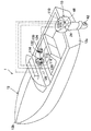
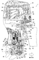
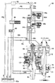
図1はこの発明の実施例に係る船外機の制御装置を船体も含めて全体的に示す概略図、図2は図1に示す船外機の部分断面拡大側面図、図3は船外機の拡大側面図である。 FIG. 1 is a schematic view showing an outboard motor control apparatus according to an embodiment of the present invention as a whole including a hull, FIG. 2 is a partially sectional enlarged side view of the outboard motor shown in FIG. 1, and FIG. It is an enlarged side view of a machine.
図1から図3において、符号1は船外機10が船体(艇体)12に搭載されてなる船舶を示す。船外機10は、図2に良く示すように、スイベルケース14、チルティングシャフト16およびスターンブラケット18を介して船体12の後尾(船尾)12aに取り付けられる。
1 to 3, reference numeral 1 denotes a ship in which an
スイベルケース14の付近には、スイベルケース14の内部に鉛直軸回りに回転自在に収容されるシャフト部20を駆動する転舵用電動モータ22と、船外機10の船体12に対するチルト角およびトリム角をチルトアップ/ダウンおよびトリムアップ/ダウンによって調整可能なパワーチルトトリムユニット(トリム角調整機構。以下「トリムユニット」という)24が配置される。転舵用電動モータ22の回転出力は減速ギヤ機構26、マウントフレーム28を介してシャフト部20に伝達され、よって船外機10はシャフト部20を転舵軸として左右に(鉛直軸回りに)回転させられて転舵される。尚、船外機10の最大転舵角は例えば左右方向にそれぞれ50degとされる。
In the vicinity of the
トリムユニット24はチルト角調整用の油圧シリンダ24aとトリム角調整用の油圧シリンダ24bを一体的に備え、油圧シリンダ24a,24bを伸縮させることで、スイベルケース14がチルティングシャフト16を回転軸として回転させられ、船外機10はチルトアップ/ダウンあるいはトリムアップ/ダウンさせられる。尚、油圧シリンダ24a,24bは、船外機10に配置された図示しない油圧回路に接続されて作動油の供給を受けて伸縮させられる。
The
船外機10の上部には、内燃機関(以下「エンジン」という)30が搭載される。エンジン30は火花点火式の水冷ガソリンエンジンで、排気量2200ccを備える。エンジン30は水面上に位置し、エンジンカバー32によって覆われる。
An internal combustion engine (hereinafter referred to as “engine”) 30 is mounted on the
エンジン30の吸気管34には、スロットルボディ36が接続される。スロットルボディ36はその内部にスロットルバルブ38を備えると共に、スロットルバルブ38を開閉駆動するスロットル用電動モータ(アクチュエータ)40が一体的に取り付けられる。
A
スロットル用電動モータ40の出力軸は減速ギヤ機構(図示せず)を介してスロットルバルブ38に接続され、スロットル用電動モータ40を動作させることでスロットルバルブ38が開閉され、エンジン30の吸気量が調量されてエンジン回転数(機関回転数)が調節される。
The output shaft of the
船外機10は、水平軸回りに回転自在に支持されると共に、その一端にプロペラ42が取り付けられ、エンジン30の動力をプロペラ42に伝達するプロペラシャフト(動力伝達軸)44と、エンジン30とプロペラシャフト44の間に介挿されると共に、1速、2速、3速からなる複数の変速段を有する変速機(自動変速機)46を備える。
The
プロペラシャフト44は、トリムユニット24の初期状態(トリム角θが初期角度の状態)において、その軸線44aが船舶1の進行方向に対して略平行となるように配置される。また、変速機46は、複数の変速段を切換自在な変速機構50と、シフト位置を前進位置、後進位置およびニュートラル位置に切換自在なシフト機構52からなる。
The
図4は変速機構50の油圧回路を模式的に示す油圧回路図である。
FIG. 4 is a hydraulic circuit diagram schematically showing a hydraulic circuit of the
図2および図4に示す如く、変速機構50は、エンジン30のクランクシャフト(図において見えず)に接続されるインプットシャフト54と、インプットシャフト54にギヤを介して接続されるカウンタシャフト56と、カウンタシャフト56に複数のギヤを介して接続されるアウトプットシャフト58とが平行に配置された平行軸式の有段式の変速機構からなる。
As shown in FIGS. 2 and 4, the
カウンタシャフト56には、後述する変速用の油圧クラッチや潤滑部に作動油(潤滑油。オイル)を圧送する油圧ポンプ(ギヤポンプ。図2にのみ示す)60が接続される。シャフト54,56,58や油圧ポンプ60などは、ケース(図2にのみ示す)62に収容される。ケース62の下部は作動油を受けるオイルパン62aを構成する。
A hydraulic pump (gear pump; only shown in FIG. 2) 60 that pumps hydraulic oil (lubricating oil, oil) to a later-described hydraulic clutch and a lubricating portion is connected to the
上記の如く構成された変速機構50においては、シャフト上に相対回転自在に配置されたギヤを変速クラッチでシャフト上に固定することで複数の変速段、詳しくは1速、2速、3速のうちのいずれかの変速段が選択(確立)され、エンジン30の出力は選択された変速段で変速され、シフト機構52、プロペラシャフト44を介してプロペラ42に伝達される。尚、各変速段の変速比は1速が最も大きく、2速、3速となるにつれて小さくなるように設定される。
In the
変速機構50について具体的に説明すると、図4に良く示すように、インプットシャフト54には、インプットプライマリギヤ64が支持される。カウンタシャフト56には、インプットプライマリギヤ64に噛合するカウンタプライマリギヤ66、カウンタ1速ギヤ68、カウンタ2速ギヤ70、カウンタ3速ギヤ72が支持される。
The
また、アウトプットシャフト58には、カウンタ1速ギヤ68に噛合するアウトプット1速ギヤ74、カウンタ2速ギヤ70と噛合するアウトプット2速ギヤ76、カウンタ3速ギヤ72に噛合するアウトプット3速ギヤ78が支持される。
The
上記において、アウトプットシャフト58に相対回転自在に支持されたアウトプット1速ギヤ74を1速用クラッチC1でアウトプットシャフト58に結合すると、1速(ギヤ。変速段)が確立する。尚、1速用クラッチC1は、ワンウェイクラッチからなり、後述する2速または3速用油圧クラッチC2,C3に油圧が供給されて2速または3速が確立し、アウトプットシャフト58の回転数がアウトプット1速ギヤ74のそれより大きくなるとき、アウトプット1速ギヤ74を空転させるように構成される。
In the above description, when the output
カウンタシャフト56に相対回転自在に支持されたカウンタ2速ギヤ70を2速用油圧クラッチC2でカウンタシャフト56に結合すると、2速(ギヤ。変速段)が確立する。また、カウンタシャフト56に相対回転自在に支持されたカウンタ3速ギヤ72を3速用油圧クラッチC3でカウンタシャフト56に結合すると、3速(ギヤ。変速段)が確立する。尚、油圧クラッチC2,C3は、油圧が供給されるとき各ギヤ70,72をカウンタシャフト56に結合する一方、油圧が供給されないとき各ギヤ70,72を空転させる。
When the counter second-
このように、クラッチC1,C2,C3によるギヤとシャフトの結合は、油圧ポンプ60から油圧クラッチC2,C3に供給される油圧を制御することで行われる。
Thus, the coupling between the gear and the shaft by the clutches C1, C2, and C3 is performed by controlling the hydraulic pressure supplied from the
図4を参照しつつ説明すると、油圧ポンプ60がエンジン30により駆動されるとき、オイルパン62aの作動油は油路80a、ストレーナ82を介して汲み上げられて吐出口60aから油路80bを介して第1切換バルブ84aに、油路80c,80dを介して第1、第2電磁ソレノイドバルブ(リニアソレノイドバルブ)86a,86bに送られる。
Referring to FIG. 4, when the
第1切換バルブ84aには、油路80eを介して第2切換バルブ84bが接続される。第1、第2切換バルブ84a,84bの内部には移動自在なスプールがそれぞれ収容され、スプールは一端側(図で左端)でスプリングによって他端側に付勢される。その他端側には、前記した第1、第2電磁ソレノイドバルブ86a,86bが油路80f,80gを介して接続される。
A
従って、第1電磁ソレノイドバルブ86aが通電(オン)されると、その内部に収容されたスプールが変位させられ、油圧ポンプ60から油路80cを介して供給される油圧は第1切換バルブ84aのスプールの他端側に出力される。これにより、第1切換バルブ84aのスプールは一端側に変位させられ、よって油路80bの作動油が油路80eに送出される。
Accordingly, when the first
第2電磁ソレノイドバルブ86bも、第1電磁ソレノイドバルブ86aと同様、通電(オン)されるときにスプールが変位させられ、油圧ポンプ60から油路80dを介して供給される油圧は第2切換バルブ84bの他端側に出力される。これにより、第2切換バルブ84bはスプールが一端側に変位させられ、よって油路80eの作動油は油路80hを介して2速用油圧クラッチC2に供給される。一方、第2電磁ソレノイドバルブ86bが通電されず(オフされ)、第2切換バルブ84bの他端側に油圧が出力されないときは油路80eの作動油は油路80iを介して3速用油圧クラッチC3に供給される。
Similarly to the first
即ち、第1、第2電磁ソレノイドバルブ86a,86bが共にオフされるときは油圧クラッチC2,C3のいずれにも油圧が供給されないため、アウトプット1速ギヤ74とアウトプットシャフト58が1速用クラッチC1で結合されて1速が確立する。
That is, when both the first and second
また、第1、第2電磁ソレノイドバルブ86a,86bが共にオンされるときは2速用油圧クラッチC2に油圧が供給されるため、カウンタ2速ギヤ70とカウンタシャフト56が結合されて2速が確立する。さらに、第1電磁ソレノイドバルブ86aがオン、第2電磁ソレノイドバルブ86bがオフされるときは3速用油圧クラッチC3に油圧が供給されるため、カウンタ3速ギヤ72とカウンタシャフト56が結合されて3速が確立する。このように、第1、第2切換バルブ84a,84bのオン・オフを制御することで、変速機46の変速段が選択される(変速制御が行われる)。
When both the first and second
尚、油圧ポンプ60からの作動油(潤滑油)は、油路80b,80j、レギュレータバルブ88やリリーフバルブ90を介して潤滑部(例えばシャフト54,56,58など)にも供給される。また、第1、第2切換バルブ84a,84bと第1、第2電磁ソレノイドバルブ86a,86bにはそれぞれ、圧抜き用の油路80kが適宜に接続される。
The hydraulic oil (lubricating oil) from the
図2の説明に戻ると、シフト機構52は、変速機構50のシャフト58に接続されると共に、鉛直軸と平行に配置されて回転自在に支持されるドライブシャフト(バーチカルシャフト)52aと、シャフト52aに接続されて回転させられる前進ベベルギヤ52bと後進ベベルギヤ52cと、プロペラシャフト44を前進ベベルギヤ52bと後進ベベルギヤ52cのいずれかに係合自在とするクラッチ52dなどからなる。
Returning to the description of FIG. 2, the
エンジンカバー32の内部にはシフト機構52を駆動するシフト用電動モータ92が配置され、その出力軸は、減速ギヤ機構94を介してシフト機構52のシフトロッド52eの上端に接続自在とされる。シフト用電動モータ92を駆動することにより、シフトロッド52eとシフトスライダ52fが適宜に変位させられ、それによってクラッチ52dを動作させてシフト位置がフォワード位置、リバース位置およびニュートラル位置の間で切り換えられる。
A shift
シフト位置がフォワード位置あるいはリバース位置のとき、変速機構50のシャフト58の回転はシフト機構52を介してプロペラシャフト44に伝達され、よってプロペラ42は回転させられ、船体12を前進あるいは後進させる方向の推力を生じる。尚、船外機10はエンジン30に取り付けられたバッテリなどの電源(図示せず)を備え、それから各電動モータ22,40,92などに動作電源が供給される。
When the shift position is the forward position or the reverse position, the rotation of the
図3に示す如く、スロットルバルブ38の付近にはスロットル開度センサ(スロットル開度変化量検出手段)96が配置され、スロットルバルブ38の開度(スロットル開度)THを示す出力を生じる。また、シフトロッド52eの付近にはニュートラルスイッチ100が配置され、変速機46のシフト位置がニュートラル位置のときにオン信号を、フォワード位置あるいはリバース位置のときにオフ信号を出力する。エンジン30のクランクシャフトの付近にはクランク角センサ(機関回転数検出手段)102が取り付けられ、所定のクランク角度ごとにパルス信号を出力する。
As shown in FIG. 3, a throttle opening sensor (throttle opening change amount detecting means) 96 is disposed in the vicinity of the
チルティングシャフト16の付近にはトリム角センサ104が配置され、船外機10のトリム角θ(船体12に対する船外機10のピッチ軸回りの回転角)に応じた出力を生じる。また、シャフト部20の近傍には転舵角センサ(転舵角検出手段)106が配置され、シャフト部22の回転角を示す出力、即ち、船外機10の船体12に対する転舵角αを示す出力を生じる。
A
転舵角センサ106は、船外機10が船体12に対して船舶1の進路を直進方向とする角度(位置)にあるときは0degを示す信号を出力すると共に、船外機10が左右方向に回転させられると、例えば右回り方向の場合はその回転角に応じた正値を、左回り方向の場合は負値を出力する。尚、各センサ104,106は具体的にはロータリエンコーダなどの回転角センサからなる。
The turning
上記した各センサやスイッチの出力は、船外機10に搭載された電子制御ユニット(Electronic Control Unit。以下「ECU」という)110に入力される。ECU110はCPUやROM,RAMなどを備えたマイクロ・コンピュータからなり、船外機10のエンジンカバー32の内部に配置される。
The outputs of the sensors and switches described above are input to an electronic control unit (hereinafter referred to as “ECU”) 110 mounted on the
図1に示す如く、船体12の操縦席112の付近には、操船者(図示せず)によって操作自在なステアリングホイール114が配置される。ステアリングホイール114は、初期位置(船舶1の進路を直進方向とする位置)から左右方向に回転操作自在とされる。ステアリングホイール114のシャフト(図示せず)には操舵角センサ116が取り付けられ、操船者によって入力されたステアリングホイール114の操舵角に応じた信号を出力する。
As shown in FIG. 1, a
操縦席112付近にはリモートコントロールボックス120が配置され、そこには操船者の操作自在に配置されるシフト・スロットルレバー(スロットルレバー)122が設けられる。レバー122は、初期位置から前後方向に揺動操作自在とされ、操船者からの前後進切換指示と、エンジン30に対する加速/減速指示を含むエンジン回転数の調節指示(別言すれば、エンジン30の目標エンジン回転数NEa)を入力する。リモートコントロールボックス120の内部にはレバー位置センサ124が取り付けられ、レバー122の位置に応じた信号を出力する。
A remote control box 120 is disposed in the vicinity of the
操縦席112付近であって船体12の重心位置には、船体12に作用する加速度を検出する加速度センサ126が配置される。加速度センサ126は、船体12の上下方向(重力軸方向)などに作用する加速度を示す出力を生じる。
An
さらに、操縦席112の付近には、エンジン30の燃費(燃料消費量)を低減させる燃費低減指示を入力するスイッチ130が操船者に手動操作自在に設けられる。スイッチ130は、操船者が燃費を重視して走行することを所望する際に操作され(押され)、操作されるとき燃費低減指示を示す信号(オン信号)を出力する。これら各センサ116,124,126およびスイッチ130の出力もECU110に入力される。
Further, a
ECU110は、入力されたセンサ出力などに基づいて各電動モータ22,92の動作を制御すると共に、変速機46の変速制御とトリムユニット24でトリム角θを調整するトリム角制御を行う。ECU110は、エンジン回転数NEやスロットル開度THに基づいてエンジン回転数NEが目標エンジン回転数NEaに一致するようにスロットル用電動モータ40の駆動を制御する。
The
このように、この実施例に係る船外機の制御装置は、操作系(ステアリングホイール114やレバー122)と船外機10の機械的な接続が断たれたDBW(Drive By Wire)方式の装置である。
As described above, the outboard motor control apparatus according to this embodiment is a DBW (Drive By Wire) system apparatus in which the operation system (the
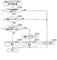
図5は、ECU110の変速制御動作とトリム角制御動作を示すフロー・チャートである。図示のプログラムは、ECU110によって所定の周期(例えば100msec)ごとに実行される。
FIG. 5 is a flowchart showing the shift control operation and trim angle control operation of the
以下説明すると、先ずS10において、変速機46の1速から3速のうちいずれの変速段を選択すべきか判定する変速段判定処理を行う。
In the following, first, in S10, a gear position determination process for determining which of the first to third gear positions of the
図6は、その変速段判定処理を示すサブ・ルーチン・フロー・チャートである。同図に示す如く、S100において変速機46のシフト位置がニュートラル位置にあるか否か判断する。この判断は、ニュートラルスイッチ100からオン信号が出力されているか否か検出することで行う。S100で否定されるとき(インギヤ時)はS102に進み、スロットル開度THをスロットル開度センサ96の出力から検出(算出)し、S104に進んで検出されたスロットル開度THの所定時間(例えば500msec)当たりの変化量(変動量)DTHを検出(算出)する。
FIG. 6 is a sub-routine flowchart showing the shift speed determination process. As shown in the figure, in S100, it is determined whether or not the shift position of the
次いでS106に進み、操船者からエンジン30に対して減速が指示されたか否か、換言すれば、エンジン30が船舶1を減速させる運転状態にあるか否か判定する。この判定は、スロットルバルブ38が閉弁方向に駆動されているか否か判断することで行う。具体的にはスロットル開度の変化量DTHが負値に設定された減速判定用の所定値DTHa(例えば−0.5deg)未満の場合、スロットルバルブ38が閉弁方向に駆動されている、即ち、減速が指示されたと判定する。
Next, in S106, it is determined whether or not the operator has instructed the
S106で否定されるときはS107に進み、後述する処理において転舵角に応じて変速が行われることを示す転舵角変速フラグのビットが0か否か判断する。S107で否定されるときは、この変速段判定処理で変速する必要がないため、以降の処理をスキップする一方、肯定されるときはS108に進み、クランク角センサ102の出力パルスをカウントしてエンジン回転数NEを検出(算出)し、S110に進んで検出されたエンジン回転数NEの変化量(変動量)DNEを検出(算出)する。変化量DNEは、前回のプログラムループで検出されたエンジン回転数NEから今回検出されたそれを減算して求める。
When the result in S106 is negative, the program proceeds to S107, and it is determined whether or not the bit of the turning angle shift flag indicating that the shift is performed according to the turning angle in the process described later is 0. If the result in S107 is negative, there is no need to shift in this gear position determination process, so the subsequent process is skipped. If the result is affirmative, the process proceeds to S108 where the output pulse of the
次いでS112に進み、加速終了後に3速に変速されたことを示す加速後3速変速済みフラグ(後述。以下「3速変速フラグ」という)のビットが0か否か判断する。3速変速フラグは初期値が0とされるため、最初のプログラムループにおいてS112の判断は通例肯定されてS114に進む。 Next, the routine proceeds to S112, where it is determined whether or not the bit of the post-acceleration 3rd speed shift flag (hereinafter referred to as “3rd speed shift flag”) indicating that the speed has been shifted to the 3rd speed after completion of acceleration is 0. Since the initial value of the 3rd speed shift flag is set to 0, the determination in S112 is normally affirmed in the first program loop, and the process proceeds to S114.
S114では、加速後2速変速済みフラグ(以下「2速変速フラグ」という)のビットが0か否か判断する。このフラグのビットは、後述する如く、加速終了後に1速から2速に変速されるとき1にセットされる一方、それ以外のとき0にリセットされる。 In S114, it is determined whether or not the bit of the post-acceleration 2nd speed completed flag (hereinafter referred to as "2nd speed shift flag") is 0. As will be described later, this flag bit is set to 1 when shifting from 1st to 2nd after the end of acceleration, and is reset to 0 otherwise.
2速変速フラグも初期値が0とされるため、最初のプログラムループにおいてS114の判断は通例肯定されてS116に進み、エンジン回転数NEが第1の所定回転数NE1以上か否か判断する。この第1の所定回転数NE1については後に説明する。 Since the initial value of the second speed shift flag is also set to 0, the determination in S114 is normally affirmed in the first program loop, and the process proceeds to S116, where it is determined whether the engine speed NE is equal to or higher than the first predetermined speed NE1. The first predetermined rotational speed NE1 will be described later.
エンジン始動直後のプログラムループにおいては通例、エンジン回転数NEは第1の所定回転数NE1未満であるため、S116の判断は否定されてS118に進む。S118では、加速中判定フラグ(後述。図で「加速中フラグ」と示す)のビットが0か否か判断する。加速中判定フラグも初期値が0とされるため、最初のプログラムループにおいてここでの判断は肯定されてS120に進む。 Usually, in the program loop immediately after the engine is started, the engine speed NE is less than the first predetermined speed NE1, so the determination in S116 is negative and the process proceeds to S118. In S118, it is determined whether or not the bit of the acceleration determination flag (described later, “acceleration flag” in the figure) is 0. Since the initial value of the determination flag during acceleration is also set to 0, the determination here is affirmed in the first program loop, and the process proceeds to S120.
S120では、操船者からエンジン30に対して加速(正確には急加速)が指示されたか否か、換言すれば、エンジン30が船舶1を加速(正確には急加速)させる運転状態にあるか否か判定する。この判定は、具体的にはスロットルバルブ38が開弁方向に急速に駆動されているか否か判断することで行う。
In S120, whether or not acceleration (accurately, sudden acceleration) is instructed by the operator to the
詳しくは、S104で検出されたスロットル開度の変化量DTHと加速判定用の所定値(所定値)DTHbとを比較し、変化量DTHが所定値DTHb以上のとき、スロットルバルブ38が開弁方向に急速に駆動されている、即ち、加速が指示されたと判定する。従って、所定値DTHbは、減速判定用の所定値DTHaに比して大きい値(正値)で、加速の指示がなされたと判定できるような値、例えば0.5degに設定される。
Specifically, the change amount DTH of the throttle opening detected in S104 is compared with a predetermined value (predetermined value) DTHb for acceleration determination. When the change amount DTH is equal to or larger than the predetermined value DTHb, the
S120で否定、即ち、エンジン30に対して加速/減速の指示がないときはS122に進み、第1、第2電磁ソレノイドバルブ86a,86b(図で「第1SOL」「第2SOL」と示す)を共にオンして変速機46において2速の変速段を選択し、次いでS124に進み、加速中判定フラグのビットを0にリセットする。
If NO in S120, that is, if the
他方、S120で肯定されるときはS126に進み、変速機46を動作させて、具体的には第1、第2電磁ソレノイドバルブ86a,86bを共にオフして変速段を2速から1速に変速(シフトダウン)する。これにより、エンジン30の出力トルクは1速にシフトダウンさせられた変速機46(正確には、変速機構50)によって増幅させられてプロペラシャフト44を介してプロペラ42に伝達され、よって加速性が上昇する。
On the other hand, when the result in S120 is affirmative, the routine proceeds to S126, where the
次いでS128に進み、加速中判定フラグのビットを1にセットする。即ち、このフラグは、スロットル開度の変化量DTHが加速判定用の所定値DTHb以上で、変速段が2速から1速に変速されるとき1にセットされる一方、それ以外のときは0にリセットされる。尚、このフラグのビットが1にセットされると、次回以降のプログラム実行時はS118で否定されてS120の処理をスキップする。 Next, in S128, the bit of the acceleration determination flag is set to 1. That is, this flag is set to 1 when the change amount DTH of the throttle opening is equal to or greater than the predetermined value DTHb for determining acceleration and the gear position is changed from the second speed to the first speed, and is set to 0 otherwise. Reset to. When the bit of this flag is set to 1, the next time program execution is denied in S118 and the process of S120 is skipped.
このように、エンジン30が始動させられてから加速が指示されるまでの通常運転時は変速段を2速にするように構成したため、急加速以外での船外機10の使い勝手を、変速機を備えない船外機と同等とすることができる。
As described above, since the gear position is set to the second speed during normal operation after the
次いでS130に進み、2速トリムフラグ(初期値0)のビットを1にセットし、プログラムを終了する。即ち、2速トリムフラグのビットが1にセットされることはスロットル開度の変化量DTHが加速判定用の所定値DTHb以上で、変速機46の変速段が1速に変速され、後述する2速トリムアップ実行判定処理においてトリムアップが行われることを、0にリセットされることは例えばエンジン30に対して減速が指示されるなど、トリムアップの必要がないことを意味する。
Next, in S130, the bit of the second speed trim flag (initial value 0) is set to 1, and the program is terminated. That is, when the bit of the second speed trim flag is set to 1, the change amount DTH of the throttle opening is equal to or greater than a predetermined value DTHb for determining acceleration, and the gear stage of the
変速機46の変速段を1速に変速した後、エンジン回転数NEが徐々に上昇し、そして1速でのトルク増幅を利用した加速が終了すると(加速領域が飽和すると)、エンジン回転数NEは第1の所定回転数(所定回転数)NE1に到達し、よってS116の判断で肯定されてS132以降の処理に進む。従って、第1の所定回転数NE1は、比較的高い値に設定され、詳しくは1速での加速が終了したと判断できる値(例えば6000rpm)とされる。
After the speed of the
S132では、エンジン回転数NEが安定しているか否か判断、換言すれば、エンジン30が安定した運転状態であるか否か判断する。この判断は、エンジン回転数の変化量DNEの絶対値を第1の既定値DNE1と比較することで行われ、変化量DNEの絶対値が第1の既定値DNE1未満の場合にエンジン回転数NEが安定していると判断する。従って、既定値DNE1はエンジン回転数NEが安定して、変化量DNEが比較的少ないと判定できるような値、例えば500rpmに設定される。
In S132, it is determined whether or not the engine speed NE is stable, in other words, whether or not the
S132で否定されるときは1速のままプログラムを終了する一方、肯定されるときはS134に進んで第1、第2電磁ソレノイドバルブ86a,86bを共にオンして変速機46の変速段を1速から2速に変速(シフトアップ)すると共に、S136に進んで2速変速フラグのビットを1にセットする。これにより、ドライブシャフト52aおよびプロペラシャフト44の回転数が上昇し、結果として船速も上昇して速度性が向上する。
When the result in S132 is negative, the program is terminated while maintaining the first speed. When the result is affirmative, the program proceeds to S134 and both the first and second
S136において2速変速フラグのビットが1にセットされると、次回以降のプログラム実行時はS114で否定されてS138に進む。このように、S138以降の処理は、2速変速フラグのビットが1にセットされるとき、換言すれば、1速での加速が終了した後に2速に変速される場合に実行される。 If the bit of the 2nd speed shift flag is set to 1 in S136, the next program execution is denied in S114 and the process proceeds to S138. As described above, the processing after S138 is executed when the bit of the 2nd speed shift flag is set to 1, in other words, when shifting to the 2nd speed after the acceleration at the 1st speed is completed.
S138では、スイッチ130がオン信号を出力しているか否か、即ち、操作者によってエンジン30の燃費低減が指示されているか否か判断する。S138で否定されるときはS140に進み、トリムアップ再開タイマ(後述)の値が所定時間を示す値を超えたか否か判断する。タイマは初期値が0とされるため、ここでの判断は否定されてS142に進み、船体12にピッチング(縦揺れ)が発生しているか否か判定する。
In S138, it is determined whether or not the
ピッチングの発生の判定は、加速度センサ126の出力に基づいて行われる。具体的には、加速度センサ126の出力に基づいて船体12の上下方向に作用する振動加速度Gzを検出(算出)し、振動加速度Gzの絶対値と許容範囲とを比較し、Gzが許容範囲にない状態が連続して複数回(例えば2回)検出されたとき、ピッチングが発生したと判定する。許容範囲は、船体12の上下方向の振動が比較的少なく、船体12にピッチングが生じていないと判定できるような範囲、例えば0〜0.5Gの範囲に設定される。
The determination of the occurrence of pitching is performed based on the output of the
S142で否定されるときは以降の処理をスキップする一方、肯定されるときはS144に進んで2速トリムフラグのビットを0にリセットする。これにより、後述する2速トリムアップ実行判定処理によってトリムアップを停止させる。次いでS146に進み、前記したトリムアップ再開タイマ(アップカウンタ)をスタートさせ、トリムアップを停止させてからの経過時間を計測する。 When the result in S142 is negative, the subsequent processing is skipped. When the result is affirmative, the process proceeds to S144 to reset the bit of the second speed trim flag to 0. Thereby, trim-up is stopped by the second-speed trim-up execution determination process described later. Next, in S146, the trim-up restart timer (up counter) described above is started and the elapsed time since the trim-up was stopped is measured.
次回以降のプログラムループにおいて、S140で肯定されるとき、即ち、トリムアップを停止後、所定時間が経過するときはS148に進み、S142と同様なピッチングの発生の判定を再度行う。S148で否定されるときはS150に進み、2速トリムフラグのビットを1にセットすると共に、S152に進んでタイマの値を0にリセットする。 In the next and subsequent program loops, when the result in S140 is affirmative, that is, when the predetermined time has elapsed after stopping the trim-up, the process proceeds to S148, and the same occurrence of pitching as in S142 is determined again. When the result in S148 is negative, the program proceeds to S150, where the bit of the second speed trim flag is set to 1, and the program proceeds to S152 to reset the timer value to 0.
これにより、後述の2速トリムアップ実行判定処理によってトリムアップを再開させる。従って、上記した所定時間は、ピッチングの発生によって一旦停止していたトリムアップを、ピッチングがなくなって再開しても良いと判断できるような値(例えば5sec)に設定される。S148で肯定されるときはS150,S152の処理をスキップする。 Thereby, trim-up is restarted by the second-speed trim-up execution determination process described later. Therefore, the predetermined time described above is set to a value (for example, 5 sec) at which it can be determined that the trimming that has been temporarily stopped due to the occurrence of pitching may be resumed without pitching. When the result in S148 is affirmative, the processes of S150 and S152 are skipped.
他方、S138で肯定されるときはS154に進み、エンジン回転数NEが第2の所定回転数NE2以上か否か判断する。第2の所定回転数NE2は、第1の所定回転数NE1に比して僅かに低い値であって、後述する如く3速に変速可能と判断できるような値、例えば5000rpmに設定される。 On the other hand, when the result in S138 is affirmative, the program proceeds to S154, in which it is determined whether or not the engine speed NE is equal to or higher than a second predetermined speed NE2. The second predetermined rotational speed NE2 is a value slightly lower than the first predetermined rotational speed NE1, and is set to a value that can be determined to be able to shift to the third speed, for example, 5000 rpm, as will be described later.
S154で肯定されるときはS156に進み、S132と同様、エンジン回転数NEが安定しているか否か判断する。即ち、エンジン回転数の変化量DNEの絶対値を第2の既定値DNE2と比較し、既定値DNE2未満の場合にエンジン回転数NEが安定していると判断する。従って、既定値DNE2は、変化量DNEが比較的少なくエンジン回転数NEが安定していると判定できるような値、例えば500rpmとされる。 When the result in S154 is affirmative, the program proceeds to S156, where it is determined whether the engine speed NE is stable as in S132. That is, the absolute value of the engine speed change amount DNE is compared with the second predetermined value DNE2, and if it is less than the predetermined value DNE2, it is determined that the engine speed NE is stable. Therefore, the predetermined value DNE2 is set to a value that can determine that the change amount DNE is relatively small and the engine speed NE is stable, for example, 500 rpm.
S156で否定、またはS154で否定されるときは前述のS140に進む一方、S156で肯定されるときはS158に進み、第1電磁ソレノイドバルブ86aをオン、第2電磁ソレノイドバルブ86bをオフして変速機46の変速段を2速から3速に変速(シフトアップ)する。これにより、エンジン回転数NEが低下するため、エンジン30の燃料消費量を低減、換言すれば、燃費が向上する。
If NO in S156 or NO in S154, the process proceeds to S140 described above. If YES in S156, the process proceeds to S158, in which the first
次いでS160に進み、2速変速フラグのビットを0にリセットし、S162に進んで3速変速フラグのビットを1にセットする。このように、3速変速フラグは、加速終了後に2速から3速に変速されるとき1にセットされる一方、それ以外のとき0にリセットされる。 Next, in S160, the bit of the second speed shift flag is reset to 0, and in S162, the bit of the third speed shift flag is set to 1. Thus, the 3rd speed shift flag is set to 1 when shifting from 2nd speed to 3rd speed after completion of acceleration, and is reset to 0 otherwise.
次いでS164に進み、3速トリムフラグ(初期値0)のビットを1にセットする。このフラグのビットが1にセットされることは、変速段が3速に変速され、後述する3速トリムダウン実行判定処理においてトリムダウンが行われることを、0にリセットされることはそのトリムダウンが不要あるいは終了したことを意味する。尚、S162で3速変速フラグのビットが1にセットされた後のプログラム実行時は、S112で否定されて、S158からS164の処理を実行して3速のままプログラムを終了する。 Next, in S164, the bit of the third speed trim flag (initial value 0) is set to 1. Setting the bit of this flag to 1 means that the gear stage is shifted to the 3rd speed, and that the trim down is performed in the 3rd speed trim down execution determination process described later. Means unnecessary or terminated. When the program is executed after the bit of the 3rd speed shift flag is set to 1 in S162, the result in S112 is negative, and the process from S158 to S164 is executed and the program is terminated with the 3rd speed.
また、S106で肯定されるとき、即ち、スロットル開度の変化量DTHが減速判定用の所定値DTHa未満のときはS166に進み、第1、第2電磁ソレノイドバルブ86a,86bを共にオンして変速機46の変速段を2速に変速する。その後、S168,S170,S172に進んで2速変速フラグ、3速変速フラグおよび加速中判定フラグのビットを全て0にリセットする。
If the determination in S106 is affirmative, that is, if the change amount DTH of the throttle opening is less than the predetermined value DTHa for deceleration determination, the process proceeds to S166 and both the first and second
次いでS174に進み、2速トリムフラグのビットを0にリセットすると共に、S176に進んでイニシャルトリムフラグ(初期値0)のビットを1にセットする。このイニシャルトリムフラグのビットが1にセットされることは、トリムユニット24を動作させてトリム角θを初期角度(具体的には0deg)にする必要があることを、0にリセットされることはその必要がないことを意味する。
Next, in S174, the bit of the second speed trim flag is reset to 0, and in S176, the bit of the initial trim flag (initial value 0) is set to 1. Setting the bit of the initial trim flag to 1 means that the
また、レバー122が操船者によって操作されて変速機46のシフト位置がニュートラル位置に切り換えられると、S100で肯定されてS178に進み、第1、第2電磁ソレノイドバルブ86a,86bをオフして変速機46の変速段を2速から1速に変速する。
When the lever 122 is operated by the operator and the shift position of the
図5フロー・チャートの説明に戻ると、次いでS12に進み、変速段が2速であって船速が最高速に到達したときのトリム角を記憶(学習)して2速用学習トリム角(所定角度)δを決定する処理を行い、その後S14に進んで3速で船速が最高速に到達したときのトリム角を記憶して3速用学習トリム角(所定角度)εを決定する処理を行う。 Returning to the description of the flow chart of FIG. 5, the process then proceeds to S12, where the trim angle when the shift speed is the second speed and the boat speed reaches the maximum speed is stored (learned), and the second trim learning trim angle ( Processing for determining the predetermined angle) δ, and then proceeding to S14, storing the trim angle when the boat speed reaches the maximum speed at the third speed, and determining the learning trim angle (predetermined angle) ε for the third speed I do.
図7はその2速用学習トリム角決定処理を示すサブ・ルーチン・フロー・チャート、図8は3速用学習トリム角決定処理を示すサブ・ルーチン・フロー・チャートである。 FIG. 7 is a sub-routine flow chart showing the second-speed learning trim angle determining process, and FIG. 8 is a sub-routine flowchart showing the third-speed learning trim angle determining process.
図7に示す如く、先ずS200において現在の変速段が2速か否か判断する。S200で否定されるときは以降の処理をスキップする一方、肯定されるときはS202に進み、スロットル開度THが最大スロットル開度であるか否か判断する。 As shown in FIG. 7, first, in S200, it is determined whether or not the current shift speed is the second speed. When the result in S200 is negative, the subsequent processing is skipped. When the result is affirmative, the process proceeds to S202, and it is determined whether or not the throttle opening TH is the maximum throttle opening.
S202で肯定されるときはS204に進み、スロットル開度THが安定しているか(変動していないか)否か判断する。この判断は、スロットル開度の変化量DTHの絶対値を変化量判定用の所定値DTHcと比較することで行われ、変化量DTHの絶対値が所定値DTHc以下の場合にスロットル開度THが安定していると判断する。従って、所定値DTHcはスロットル開度THが安定している、換言すれば、変化量DTHが比較的少ない状態であると判定できるような値、例えば2degとされる。 When the result in S202 is affirmative, the program proceeds to S204, in which it is determined whether the throttle opening TH is stable (is not changing). This determination is made by comparing the absolute value of the change amount DTH of the throttle opening with a predetermined value DTHc for determining the change amount. When the absolute value of the change amount DTH is less than or equal to the predetermined value DTHc, the throttle opening TH is Judge that it is stable. Therefore, the predetermined value DTHc is set to a value that can determine that the throttle opening TH is stable, in other words, the change amount DTH is relatively small, for example, 2 deg.
S204またはS202で否定されるときは以降の処理をスキップする一方、S204で肯定されるとき、別言すれば、スロットル開度THが最大スロットル開度で安定し、エンジン30が船舶1の速度を最高速に到達させることのできる運転状態にあるときはS206に進み、エンジン回転数の変化量DNEが正値(例えば500rpm)に設定される第3の既定値DNE3を超えるか否か判断する。
When the determination in S204 or S202 is negative, the subsequent processing is skipped, while when the determination in S204 is positive, in other words, the throttle opening TH is stabilized at the maximum throttle opening, and the
このS206の処理を最初に実行するときは、S204でエンジン30が上記した運転状態にあると判定された直後であるため、変化量DNEは正側に大きく、よって通例肯定されてS208に進み、トリムユニット24を動作させてトリムアップを実行する、正確にはトリムアップを開始する。このトリムアップの開始によって船速は上昇する。
Since the process of S206 is first executed immediately after it is determined in S204 that the
他方、S206で否定されるときはS210に進み、エンジン回転数の変化量DNEが負値(例えば−500rpm)に設定される第4の既定値DNE4未満か否か判断する。S210で肯定されるときは、例えばS208で行われたトリムアップによってトリム角θが過大となってしまったことを意味し、そのようなときはS212に進んでトリムダウンを実行してトリム角θを適宜に調整する。 On the other hand, when the result in S206 is negative, the program proceeds to S210, in which it is determined whether or not the engine speed change amount DNE is less than a fourth predetermined value DNE4 set to a negative value (for example, -500 rpm). If the result in S210 is affirmative, it means that the trim angle θ has become excessive due to, for example, the trim-up performed in S208, and in such a case, the process proceeds to S212 and trim-down is performed to perform the trim angle θ. Is adjusted appropriately.
S210で否定されるとき、換言すれば、エンジン回転数の変化量DNEが第3の既定値DNE3と第4の既定値DNE4で規定される所定範囲内(即ち、DNE4≦DNE≦DNE3)にあるときは、エンジン回転数NEが高速回転領域で飽和し、船速が最高速に到達したと判断(推定)し、S214に進んでトリムアップ(またはトリムダウン)を停止する。従って、第3、第4の既定値DNE3,DNE4によって規定される所定範囲は、船速が最高速に到達したと推定できるような値に設定される。 When the result in S210 is NO, in other words, the engine speed change amount DNE is within a predetermined range defined by the third predetermined value DNE3 and the fourth predetermined value DNE4 (that is, DNE4 ≦ DNE ≦ DNE3). When the engine speed NE is saturated in the high-speed rotation region, it is determined (estimated) that the boat speed has reached the maximum speed, and the process proceeds to S214 to stop trim-up (or trim-down). Accordingly, the predetermined range defined by the third and fourth predetermined values DNE3 and DNE4 is set to a value that can be estimated that the boat speed has reached the maximum speed.
次いでS216に進み、トリム角センサ104の出力に基づいて現在のトリム角θを検出、別言すれば、トリムアップを停止したときのトリム角θ(例えば10deg)を検出して記憶し、記憶されたトリム角θを2速用学習トリム角δ(後述)として決定する。
Next, in S216, the current trim angle θ is detected based on the output of the
そしてS218に進み、2速用学習トリム角決定済みフラグ(初期値0)のビットを1にセットしてプログラムを終了する。即ち、このフラグが1にセットされることは2速用学習トリム角δが決定されたことを意味する。 Then, the process proceeds to S218, where the bit of the second-speed learning trim angle determined flag (initial value 0) is set to 1, and the program ends. That is, setting this flag to 1 means that the learning trim angle for second speed δ has been determined.
次いで図8の3速用学習トリム角決定処理について説明すると、先ずS300において現在の変速段が3速か否か判断する。S300で否定されるときは以降の処理をスキップする一方、肯定されるときはS302に進み、スロットル開度THが最大スロットル開度であるか否か判断する。 Next, the third-speed learning trim angle determination process in FIG. 8 will be described. First, in S300, it is determined whether or not the current shift speed is the third speed. When the result in S300 is negative, the subsequent processes are skipped, while when the result is affirmative, the process proceeds to S302 to determine whether or not the throttle opening TH is the maximum throttle opening.
S302で肯定されるときはS304に進み、スロットル開度の変化量DTHの絶対値が変化量判定用の所定値DTHc以下か否か判断する。このS302,S304は、前記したS202,S204と同様、スロットル開度THが最大スロットル開度で安定し、エンジン30が船舶1の速度を最高速に到達させることのできる運転状態にあるか否か判断する処理である。
When the result in S302 is affirmative, the program proceeds to S304, in which it is determined whether or not the absolute value of the change amount DTH of the throttle opening is equal to or smaller than a predetermined value DTHc for change amount determination. In S302 and S304, as in S202 and S204 described above, whether or not the throttle opening TH is stable at the maximum throttle opening and the
S302またはS304で否定されるときは以降の処理をスキップする。他方、S304で肯定されるときはS306に進み、エンジン回転数の変化量DNEが負値(例えば−500rpm)に設定される第5の既定値DNE5未満か否か判断する。 When the result in S302 or S304 is NO, the subsequent processing is skipped. On the other hand, when the result in S304 is affirmative, the program proceeds to S306, in which it is determined whether or not the engine speed change amount DNE is less than a fifth predetermined value DNE5 set to a negative value (for example, -500 rpm).
このS306の処理を最初に実行するときは、変速段が3速に変速(シフトアップ)されてS300で肯定された後であるため、変化量DNEは負側に大きくなり、よって通例肯定されてS308に進む。S308では、トリムユニット24を動作させてトリムダウンを実行する、正確にはトリムダウンを開始する。尚、変速段が2速から3速に変速された直後においては、2速のときのトリム角をトリムダウンによって僅かに減少させることで、船速は上昇することとなる。
The first time that the process of S306 is executed is after the gear stage has been shifted to the third speed (shifted up) and affirmed in S300, the amount of change DNE increases to the negative side, and is therefore generally affirmed. The process proceeds to S308. In step S308, the
S306で否定されるときはS310に進み、エンジン回転数の変化量DNEが正値(例えば500rpm)に設定される第6の既定値DNE6を超えているか否か判断する。S310で肯定されるときは、例えばS308で行われたトリムダウンによってトリム角θが過小となってしまったことを意味し、そのようなときはS312に進んでトリムアップを実行してトリム角θを適宜に調整する。 When the result in S306 is negative, the program proceeds to S310, in which it is determined whether or not the engine speed change amount DNE exceeds a sixth predetermined value DNE6 set to a positive value (for example, 500 rpm). If the result in S310 is affirmative, it means that the trim angle θ has become too small due to, for example, the trim down performed in S308. In such a case, the process proceeds to S312 to perform trim-up and the trim angle θ. Is adjusted appropriately.
S310で否定されるとき、換言すれば、エンジン回転数の変化量DNEが第5の既定値DNE5と第6の既定値DNE6で規定される第2の所定範囲内(即ち、DNE5≦DNE≦DNE6)にあるときは、エンジン回転数NEが高速回転領域で飽和し、船速が最高速に到達したと判断(推定)し、S314に進んでトリムダウン(またはトリムアップ)を停止する。従って、第5、第6の既定値DNE5,DNE6によって規定される第2の所定範囲は、船速が最高速に到達したと推定できるような値に設定される。 When the result in S310 is negative, in other words, the engine speed change amount DNE is within the second predetermined range defined by the fifth predetermined value DNE5 and the sixth predetermined value DNE6 (that is, DNE5 ≦ DNE ≦ DNE6). ), The engine speed NE is saturated in the high speed region, and it is determined (estimated) that the boat speed has reached the maximum speed, and the process proceeds to S314 to stop trim down (or trim up). Accordingly, the second predetermined range defined by the fifth and sixth predetermined values DNE5 and DNE6 is set to a value that allows the ship speed to be estimated to have reached the highest speed.
次いでS316に進み、現在のトリム角θ、別言すれば、トリムダウンを停止したときのトリム角θ(例えば8deg)を検出して記憶し、記憶されたトリム角θを3速用学習トリム角ε(後述)として決定する。 Next, the process proceeds to S316, in which the current trim angle θ, in other words, the trim angle θ when trim down is stopped (for example, 8 deg) is detected and stored, and the stored trim angle θ is stored as the third trim learning trim angle. It is determined as ε (described later).
そしてS318に進み、3速用学習トリム角決定済みフラグ(初期値0)のビットを1にセットしてプログラムを終了する。即ち、このフラグが1にセットされることは3速用学習トリム角εが決定されたことを意味する。 Then, the process proceeds to S318, in which the bit of the third-speed learning trim angle determined flag (initial value 0) is set to 1, and the program ends. That is, setting this flag to 1 means that the learning trim angle ε for the third speed has been determined.
上記したS12,S14について詳説すると、変速段が2速のときと3速のときとでは、船速を最高速に到達させることのできる最適なトリム角は相違する。具体的には3速において最適なトリム角は、2速のそれに比して僅かに小さい値となる。従って、S12,S14においては、変速段が2速、3速のときの最適なトリム角をエンジン回転数の変化量DNEに基づいてトリムアップ/ダウンを行って設定すると共に、そこで得た最適なトリム角を学習値として記憶するようにした。そして、後述する如く、次回以降の2速、3速での運転においてその学習値を適用するようにした。 The above-described S12 and S14 will be described in detail. The optimum trim angle at which the boat speed can be reached at the maximum speed differs depending on whether the shift speed is the second speed or the third speed. Specifically, the optimum trim angle at the third speed is slightly smaller than that at the second speed. Accordingly, in S12 and S14, the optimum trim angle when the gear stage is 2nd and 3rd is set by performing trim up / down based on the engine speed change amount DNE, and the optimum trim angle obtained there is set. The trim angle is stored as a learning value. As will be described later, the learned value is applied to the second and third speed driving after the next time.
図5フロー・チャートの説明に戻ると、次いでS16に進み、学習トリム角δ,εが決定されたか否かの判定処理を行う。 Returning to the description of the flowchart of FIG. 5, the process then proceeds to S16, in which it is determined whether or not the learning trim angles δ and ε have been determined.
図9はその学習トリム角決定判定処理を示すサブ・ルーチン・フロー・チャートである。図9に示す如く、S400において2つの学習トリム角δ,εが決定されたことを示す学習トリム角決定済みフラグのビットが0か否か判定する。このフラグは初期値が0に設定されるため、最初のプログラムループにおいてS400の判断は通例肯定されてS402に進む。 FIG. 9 is a subroutine flowchart showing the learning trim angle determination process. As shown in FIG. 9, it is determined whether or not the bit of the learning trim angle determined flag indicating that the two learning trim angles δ and ε have been determined in S400 is zero. Since the initial value of this flag is set to 0, the determination in S400 is normally affirmed in the first program loop, and the process proceeds to S402.
S402では、2速用学習トリム角決定済みフラグのビットが1か否か判断する。S402で肯定されるときはS404に進み、3速用学習トリム角決定済みフラグのビットが1か否か判断する。S404またはS402で否定されるときは以降の処理をスキップする一方、S404で肯定されるときはS406に進み、トリム制御開始フラグ(初期値0)のビットを1にセットする。このトリム制御開始フラグのビットが1にセットされることは、後述するような学習トリム角δ,εを用いたトリム角の制御が開始できる(許可されている)ことを、0にリセットされることはその制御が開始できない、あるいは許可されていないことを意味する。 In S402, it is determined whether or not the bit of the second-speed learning trim angle determined flag is 1. When the result in S402 is affirmative, the program proceeds to S404, in which it is determined whether the bit of the third-speed learning trim angle determined flag is 1. When the result in S404 or S402 is negative, the subsequent processing is skipped. When the result in S404 is positive, the process proceeds to S406, and the bit of the trim control start flag (initial value 0) is set to 1. Setting the bit of the trim control start flag to 1 resets the trim angle control using learning trim angles δ and ε, which will be described later, to 0 (allowed). This means that the control cannot be started or is not allowed.
次いでS408に進み、学習トリム角決定済みフラグのビットを1にセットしてプログラムを終了する。このフラグのビットが1にセットされると、次回以降のプログラム実行時はS400で否定され、S402からS408の処理をスキップする。尚、トリム制御開始フラグと学習トリム角決定済みフラグは、船外機10の電源が操船者によってオフされるとき、0にリセットされる。
Next, in S408, the bit of the learning trim angle determined flag is set to 1, and the program is terminated. When the bit of this flag is set to 1, the next and subsequent program executions are denied in S400, and the processing from S402 to S408 is skipped. The trim control start flag and the learned trim angle determined flag are reset to 0 when the power of the
図5にあっては、次いでS18に進み、転舵が開始されてトリム角θを調整すべきか否か、およびシフトアップ/ダウンすべきか否かの判定処理を行う。 In FIG. 5, next, the process proceeds to S <b> 18, where determination processing is performed as to whether or not the steering is started and the trim angle θ should be adjusted, and whether or not to shift up / down.
図10はその転舵判定処理を示すサブ・ルーチン・フロー・チャートである。図示の如く、S500において転舵角αを転舵角センサ106の出力から検出(算出)し、S502に進んで検出された転舵角αの絶対値の所定時間(例えば500msec)当たりの変化量(変動量)Dαを算出する。
FIG. 10 is a sub-routine flowchart showing the steering determination process. As shown in the figure, the turning angle α is detected (calculated) from the output of the
次いでS504に進み、検出された転舵角αに基づき、転舵が開始されてキャビテーションが発生し易い状態か否か、また転舵が開始されている場合はその転舵の大小を判定する。具体的に説明すると、転舵角αの絶対値が比較的小さい値(例えば5deg)に設定された第1の所定転舵角η未満のときは転舵がないあるいは僅かであると判断し、S506に進んで2速用学習トリム角δと3速用学習トリム角εをそのまま後述するトリム角θを調整する処理(2,3速トリムアップ/ダウン実行判定処理)において用いる。次いでS508に進み、転舵角変速フラグのビットを0にリセットしてプログラムを終了する。 Next, the process proceeds to S504, and based on the detected turning angle α, it is determined whether or not turning is started and cavitation is likely to occur, and if turning is started, the magnitude of the turning is determined. More specifically, when the absolute value of the turning angle α is less than the first predetermined turning angle η set to a relatively small value (for example, 5 deg), it is determined that there is no or little turning, Proceeding to S506, the second-speed learning trim angle δ and the third-speed learning trim angle ε are used as they are in the process of adjusting the trim angle θ described later (second / third speed trim up / down execution determination process). Next, in S508, the bit of the turning angle shift flag is reset to 0 and the program is terminated.
S504において転舵角αの絶対値が第1の所定転舵角η以上で、かつ第1の所定転舵角ηより大きい値(例えば10deg)に設定された第2の所定転舵角(所定転舵角)ζ未満のときは転舵が開始されてキャビテーションが発生し易いが、その転舵は比較的小さいと判断し、S510に進み、2速用学習トリム角δと3速用学習トリム角εからそれぞれ既定角度(例えば3deg)を減算し、よって得た値を後述のトリム角θを調整する処理で使用する。 In S504, a second predetermined turning angle (predetermined), in which the absolute value of the turning angle α is equal to or larger than the first predetermined turning angle η and larger than the first predetermined turning angle η (for example, 10 deg). When the steering angle is less than ζ, steering is started and cavitation is likely to occur, but it is determined that the steering is relatively small, and the process proceeds to S510 and the learning trim angle δ for the second speed and the learning trim for the third speed A predetermined angle (for example, 3 deg) is subtracted from each angle ε, and the obtained value is used in a process for adjusting a trim angle θ described later.
上記の如く構成することで、トリム角θが例えば2速用学習トリム角δであった場合、トリム角を調整する処理においてトリムダウンが開始されてトリム角θは減少させられることとなる。このように、転舵が開始されるとき、転舵角αに応じてトリム角θを減少させるようにする。次いでS512に進み、転舵角変速済みフラグのビットが1か否か判断する。このフラグは初期値が0に設定されるため、ここでは通例否定されてS514に進み、転舵角変速フラグのビットを0にリセットしてプログラムを終了する。 With the above configuration, when the trim angle θ is the second-speed learning trim angle δ, for example, trim down is started in the process of adjusting the trim angle, and the trim angle θ is reduced. Thus, when the steering is started, the trim angle θ is decreased according to the steering angle α. Next, in S512, it is determined whether or not the bit of the turning angle shift completed flag is 1. Since the initial value of this flag is set to 0, it is generally denied here and the process proceeds to S514, the bit of the turning angle shift flag is reset to 0, and the program ends.
S504において転舵角αの絶対値が第2の所定転舵角ζ以上のときは転舵が開始されていると共に、その転舵は比較的大きいと判断し、S516に進む。S516では、S510と同様、2,3速用学習トリム角δ,εから既定角度を減算し、よって得た値をトリム角θを調整する処理で使用する。これにより、トリム角θは減少させられる。 When the absolute value of the turning angle α is equal to or larger than the second predetermined turning angle ζ in S504, it is determined that the turning is started and the turning is relatively large, and the process proceeds to S516. In S516, similar to S510, the predetermined angle is subtracted from the learning trim angles δ, ε for the second and third speeds, and the obtained value is used in the process of adjusting the trim angle θ. As a result, the trim angle θ is reduced.
また、転舵が大きいときは減速することで、旋回をスムーズに行うことができるため、以下の処理においてはさらにシフトダウンを行うようにした。具体的には、S518において転舵角変速フラグのビットを1にセットする。即ち、このフラグのビットが1にセットされることは転舵角αに応じて変速が行われることを、0にリセットされることはそのような変速が行われないことを意味する。 In addition, when the turning is large, the vehicle can be smoothly turned by decelerating. Therefore, further downshifting is performed in the following processing. Specifically, the bit of the turning angle shift flag is set to 1 in S518. That is, setting the bit of this flag to 1 means that a shift is performed according to the turning angle α, and resetting to 0 means that such a shift is not performed.
次いでS520に進み、今回の転舵が急速な転舵(急転舵)か否か判定する。この判定は、転舵角の変化量Dαに基づいて行われる。詳しくは、転舵角の変化量Dαと急転舵判定用のしきい値Dα1とを比較し、変化量Dαがしきい値Dα1以上のとき、今回の転舵が急速な転舵であると判定する。従って、しきい値Dα1は急転舵と判定できるような値、例えば10degに設定される。 Next, in S520, it is determined whether or not the current steering is a rapid steering (rapid steering). This determination is made based on the change amount Dα of the turning angle. Specifically, the change amount Dα of the turning angle is compared with the threshold value Dα1 for sudden turning determination, and when the change amount Dα is equal to or greater than the threshold value Dα1, it is determined that the current turning is rapid turning. To do. Therefore, the threshold value Dα1 is set to a value that can be determined as sudden turning, for example, 10 deg.
S520で否定されるときはS522に進み、第1、第2電磁ソレノイドバルブ86a,86bの動作を制御してシフトダウンを行う。具体的には、変速段が2速のときは1速に、3速のときは2速にシフトダウンする。次いでS524に進み、転舵角変速済みフラグのビットを1にセットする。即ち、このフラグのビットは、転舵角αに応じてシフトダウンがなされたとき1にセットされる一方、それ以外のとき0にリセットされる。
When the result in S520 is negative, the program proceeds to S522, in which the operation of the first and second
次いでS526に進み、レバー122の位置に応じて設定されていたエンジン30の目標エンジン回転数NEaを、エンジン30の出力トルクが最大となるように変更する。具体的には、レバー122の位置に拘らず、目標エンジン回転数NEaにエンジン30の出力トルクが最大となるエンジン回転数(以下「最大トルク回転数」という)NEtmaxをセットする。
Next, in S526, the target engine speed NEa of the
図11は、この実施例に係るエンジン30のエンジン回転数NEに対する出力トルクの特性を示す特性図(エンジン性能線図)である。
FIG. 11 is a characteristic diagram (engine performance diagram) showing the characteristics of the output torque with respect to the engine speed NE of the
最大トルク回転数NEtmaxについて図11を参照しつつ説明すると、エンジン30の出力トルクは、エンジン回転数NEが低回転のときは比較的低く、回転数が上昇するに連れて徐々に増加し、所定の回転数に到達するときに最大となる(図で「Tmax」と示す)。このときの回転数が上記したエンジン30の最大トルク回転数NEtmaxである。尚、エンジン回転数NEが最大トルク回転数NEtmaxを超えてさらに上昇すると、出力トルクは徐々に減少する。
The maximum torque rotational speed NEtmax will be described with reference to FIG. 11. The output torque of the
従って、転舵角αに応じてシフトダウンがなされた後、エンジン30の出力トルクが最大となるように目標エンジン回転数NEaを変更、具体的には、目標エンジン回転数NEaを最大トルク回転数NEtmaxに設定することで、エンジン30は、回転が急激に吹き上がることなく、出力トルクが最大となるよう、その動作が制御されることとなる。
Therefore, after the downshift is made in accordance with the turning angle α, the target engine speed NEa is changed so that the output torque of the
他方、S520で肯定されるときはS528に進み、現在の変速段が3速か否か判断する。S528で否定されるときは前述したS522に進む一方、肯定されるときはS530に進んで変速段を3速から1速にシフトダウンする。S530の処理後はS524,S526の処理を実行してプログラムを終了する。 On the other hand, when the result in S520 is affirmative, the program proceeds to S528, in which it is determined whether or not the current shift speed is the third speed. When the result in S528 is negative, the program proceeds to S522 described above. When the result is affirmed, the program proceeds to S530 and the gear position is shifted down from the third speed to the first speed. After the processing of S530, the processing of S524 and S526 is executed and the program is terminated.
また、S516で学習トリム角δ,εを減算すると共に、S522またはS530でシフトダウンがなされた後のプログラムループにおいて、上記した転舵が終了し、操船者によってステアリングホイール114が初期位置に戻されて転舵角αが徐々に減少し、第2の所定転舵角ζ未満となる場合、先ずS504で転舵が比較的小さいと判断されてS510に進む。
Further, in S516, the learning trim angles δ and ε are subtracted, and in the program loop after the downshift is performed in S522 or S530, the above-described steering is finished, and the
2,3速用学習トリム角δ,εはS516で既に減算されているため、そのままS512に進み、そこで肯定されてS532に進む。S532では、転舵によってシフトダウンした変速機46を、シフトダウン前の変速段となるようにシフトアップする。このように、転舵が終了した後、検出された転舵角αの減少に応じてシフトアップする。そして、S534に進み、転舵角変速済みフラグのビットを0にリセットする。
Since the learning trim angles δ and ε for the second and third speeds have already been subtracted in S516, the process proceeds to S512, where it is affirmed and the process proceeds to S532. In S532, the
転舵角αがさらに減少して第1の所定転舵角η未満になると、トリム角θを減少させる必要はないため、S504からS506に進み、減少させていた学習トリム角δ,εを元に戻すようにする。これにより、トリム角を調整する処理においてトリムアップが開始されてトリム角θは増加させられることとなる。このように、S532でシフトアップがなされた後は検出された転舵角αの減少に応じてトリム角θを増加させるようにする。 When the turning angle α is further reduced to be less than the first predetermined turning angle η, it is not necessary to reduce the trim angle θ. Therefore, the process proceeds from S504 to S506, and the learning trim angles δ and ε that have been reduced are restored. Return to. As a result, trim-up is started in the process of adjusting the trim angle, and the trim angle θ is increased. As described above, after the shift-up is performed in S532, the trim angle θ is increased in accordance with the detected decrease in the turning angle α.
図5フロー・チャートの説明に戻ると、次いでS20に進み、変速段が2速であって船外機10のトリムアップ/ダウンを実行すべきか否かの判定処理を行い、その後S22に進んで3速であって船外機10のトリムアップ/ダウンを実行すべきか否かの判定処理を行う。
Returning to the description of the flow chart of FIG. 5, the process then proceeds to S20, where it is determined whether or not the gear stage is 2nd and trimming up / down of the
図12はその2速トリムアップ/ダウン実行判定処理を示すサブ・ルーチン・フロー・チャート、図13は3速トリムアップ/ダウン実行判定処理を示すサブ・ルーチン・フロー・チャートである。 FIG. 12 is a sub-routine flow chart showing the 2-speed trim up / down execution determination process, and FIG. 13 is a sub-routine flow chart showing the 3-speed trim up / down execution determination process.
図12に示すように、先ずS600においてトリム制御開始フラグのビットが1か否か判断する。S600で否定されるときはS602に進み、トリムアップを停止、正確にはトリムアップを行わない。 As shown in FIG. 12, first, in S600, it is determined whether or not the bit of the trim control start flag is 1. When the result in S600 is negative, the program proceeds to S602, where the trim-up is stopped and the trim-up is not accurately performed.
S600で肯定されるときはS604に進み、2速トリムフラグのビットが1か否か判断する。S604で否定されるときはトリムアップの必要がないことから、S602に進んでトリムアップを行わない。一方、S604で肯定されるとき(例えばスロットル開度の変化量DTHが加速判定用の所定値DTHb以上で、変速段を1速に変速している状態のとき)はS606に進み、エンジン回転数NEが第3の所定回転数(所定回転数)NE3以上か否か判断する。 When the result in S600 is affirmative, the program proceeds to S604, in which it is determined whether the bit of the second speed trim flag is 1. When the result in S604 is NO, there is no need for trim-up, so the process proceeds to S602 and trim-up is not performed. On the other hand, when the result in S604 is affirmative (for example, when the change amount DTH of the throttle opening is equal to or greater than a predetermined value DTHb for acceleration determination and the gear stage is shifted to the first speed), the process proceeds to S606 and the engine speed is increased. It is determined whether NE is greater than or equal to a third predetermined rotational speed (predetermined rotational speed) NE3.
第3の所定回転数NE3は、加速が終了して変速段を1速から2速に戻すしきい値である第1の所定回転数NE1より低い値とされ、例えば5000rpmに設定される。従って、S606は、エンジン回転数NEが1速での加速が終了して変速段を1速から2速に戻す直前の状態を示しているか否か判断する処理とも言える。 The third predetermined rotational speed NE3 is set to a value lower than the first predetermined rotational speed NE1, which is a threshold value at which the acceleration is completed and the gear position is returned from the first speed to the second speed, and is set to, for example, 5000 rpm. Therefore, it can be said that S606 is processing for determining whether or not the acceleration at the first speed of the engine speed NE has ended and the state immediately before the shift speed is returned from the first speed to the second speed.
S606で否定されるときはトリムアップを開始するタイミングではないため、S602に進み、トリムアップを実行することなくプログラムを終了する。他方、S606で肯定されるときはS608に進み、トリム角θが2速用学習トリム角δか否か判断する。 When the result in S606 is NO, it is not the timing to start trim-up, so the process proceeds to S602, and the program is terminated without executing trim-up. On the other hand, when the result in S606 is affirmative, the program proceeds to S608, in which it is determined whether or not the trim angle θ is the second-speed learning trim angle δ.
S608で否定されるときはS610に進み、トリムユニット24を動作させてトリムアップまたはトリムダウンを実行する。S610を最初に実行するときは、トリム角θは通例0degであるため、ここではトリムアップを開始する。即ち、エンジン回転数NEが第3の所定回転数NE3以上のとき、トリムアップを開始する。このように、2速用学習トリム角δが決定された後は、加速が終了して変速段を1速から2速に戻す前にトリムアップを開始することで、船速は上昇する。
When the result in S608 is negative, the program proceeds to S610, where the
そして、トリムアップによってトリム角θが調整され、その後のプログラムループにおいてS608で肯定されるときはS612に進み、2速トリムフラグのビットを0にリセットすると共に、S614に進んでトリムアップ/ダウンを停止する。このように、2速のときはトリム角θを学習トリム角δに調整することで、船速が最高速に到達する。 Then, the trim angle θ is adjusted by trim-up, and if the result in S608 is positive in the subsequent program loop, the process proceeds to S612, the bit of the second speed trim flag is reset to 0, and the process proceeds to S614 to perform trim-up / down. Stop. Thus, at the second speed, the boat speed reaches the highest speed by adjusting the trim angle θ to the learning trim angle δ.
また、前述したS510またはS516の処理において2速用学習トリム角δが既定角度減算された後のプログラム実行時はS608で否定されてS610に進み、トリム角θが減算された2速用学習トリム角δとなるまでトリムダウンを実行する。そして、転舵が終了して2速用学習トリム角δが元に戻されるときも同様に、S608で否定されてS610に進み、トリム角θが元に戻された2速用学習トリム角δとなるまでトリムアップを実行する。 Further, when the program is executed after the predetermined speed subtraction of the second speed learning trim angle δ in the above-described processing of S510 or S516, the result is negative in S608 and the process proceeds to S610, where the trim angle θ is subtracted. Trim down is performed until the angle δ is reached. Similarly, when the turning is finished and the second-speed learning trim angle δ is returned to the original, the second-speed learning trim angle δ in which the trim angle θ is returned to the original is negated in S608 and proceeds to S610. Trim up until
次いで図13の3速トリムダウン実行判定処理について説明すると、S700においてトリム制御開始フラグのビットが1か否か判断する。S700で否定されるときはS702に進み、トリムダウンを停止、正確にはトリムダウンを行わない。 Next, the third speed trim down execution determination process of FIG. 13 will be described. In S700, it is determined whether or not the bit of the trim control start flag is 1. When the result in S700 is negative, the program proceeds to S702, where the trim down is stopped, and the trim down is not performed accurately.
S700で肯定されるときはS704に進み、3速トリムフラグのビットが1か否か判断する。S704で否定されるときはトリムダウンの必要がないことから、S702に進んでトリムダウンを行わず、肯定されるとき、即ち、変速段が3速に変速されているときはS706に進み、トリム角θが3速用学習トリム角εか否か判断する。 When the result in S700 is affirmative, the program proceeds to S704, in which it is determined whether the bit of the 3rd speed trim flag is 1. If the result in S704 is negative, trimming is not necessary, so the process proceeds to S702 and trimming is not performed. If the result is affirmative, that is, if the shift stage is shifted to the third speed, the process proceeds to S706 and trimming is performed. It is determined whether the angle θ is the third-speed learning trim angle ε.
S706で否定されるときはS708に進み、トリムユニット24を動作させてトリムダウンまたはトリムアップを行う。S708を最初に実行するときは、トリム角θは通例3速用学習トリム角εより大きい値の2速用学習トリム角δであるため、ここではトリムダウンを開始する。そして、トリムダウンによってトリム角θが調整され、その後のプログラムループにおいてS706で肯定されるときはS710に進み、3速トリムフラグのビットを0にリセットすると共に、S712に進んでトリムダウンを停止する。このように、3速用学習トリム角εが決定された後は、変速段が3速に変速されるときにトリムダウンを開始し、トリム角θを学習トリム角εに調整することで、船速は最高速に到達する。
When the result in S706 is negative, the program proceeds to S708, where the
また、前述したS510やS516の処理において3速用学習トリム角εが既定角度減算された後のプログラム実行時はS706で否定されてS708に進み、トリム角θが減算された3速用学習トリム角εとなるまでトリムダウンを実行する。そして、転舵が終了して3速用学習トリム角εが元に戻されるときも同様に、S706で否定されてS708に進み、トリム角θが元に戻された3速用学習トリム角εとなるまでトリムアップを実行する。 In addition, when the program is executed after the third-speed learning trim angle ε is subtracted from the predetermined angle in the processing of S510 and S516 described above, the determination is negative in S706 and the process proceeds to S708, where the trim angle θ is subtracted. Trim down until the angle ε is reached. Similarly, when the turning is finished and the third-speed learning trim angle ε is returned to the original value, the third-speed learning trim angle ε in which the trim angle θ is returned to the original state is negated in S706 and proceeds to S708. Trim up until
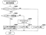
図5にあっては、次いでS24に進み、トリム角θを初期角度に戻すためのトリムダウンを実行すべきか否かの判定処理を行う。 In FIG. 5, the process then proceeds to S24, in which it is determined whether or not to perform trim down for returning the trim angle θ to the initial angle.
図14はそのイニシャルトリムダウン実行判定処理を示すサブ・ルーチン・フロー・チャートである。図示の如く、S800においてイニシャルトリムフラグのビットが1か否か判断する。S800で否定されるときはS802に進み、トリムダウンを行わない。 FIG. 14 is a sub-routine flowchart showing the initial trim down execution determination process. As shown in the figure, it is determined in S800 whether the bit of the initial trim flag is 1. When the result in S800 is negative, the program proceeds to S802 and trimming is not performed.
他方、S800で肯定されるときはS804に進み、トリム角θが初期角度より大きいか否か判断する。S804で肯定されるときはS806に進み、トリムユニット24を動作させてトリムダウンを開始してトリム角θが初期角度となるように(トリム角θを初期角度に戻すように)する。S804で否定されるときはS808に進んでイニシャルトリムフラグのビットを0にリセットし、次いでS810に進み、トリムダウンを停止してプログラムを終了する。
On the other hand, when the result in S800 is affirmative, the program proceeds to S804, in which it is determined whether the trim angle θ is larger than the initial angle. When the result in S804 is affirmative, the program proceeds to S806, in which the
図15は上記した処理のうち、転舵が行われたときの船外機10の動作を説明するタイム・チャートであり、図16はその説明図である。尚、以下においては、S12,S14で2,3速用学習トリム角δ,εが既に決定されているものとする。また、図16において符号yは船外機10の前後方向を、符号zは上下方向を示し、符号Wは海水あるいは淡水を、符号Sはその水面を示す。前後方向yと上下方向zは、船外機10における前後、上下を意味し、船外機10のチルト角やトリム角によっては必ずしも重力方向あるいは水平方向とは一致しない。
FIG. 15 is a time chart for explaining the operation of the
以下説明すると、先ず時刻t0からt1の通常運転時において変速機46の変速段を2速に設定し(S122)、その後操船者のシフト・スロットルレバー122の操作によってスロットルバルブ38が開弁させられ、時刻t1においてスロットル開度の変化量DTHが加速判定用の所定値DTHb以上のとき(S120)、2速から1速に変速する(S126)。
In the following description, first, during the normal operation from time t0 to t1, the gear position of the
図16にあっては、時刻t0からt1のときは(a)に示す如く、船体12と船外機10は共に水平状態にあり、トリム角θは初期角度(0deg)である。時刻t1での加速によって変速段を1速にし、船速が上昇すると、船体12は、図16(b)に示す如く、船首12bが持ち上がる一方、船尾12aが沈み込む、いわゆるハンプ状態となる。同図から分かるように、このときのプロペラシャフト44の軸線44aの方向は船舶1の進行方向に対して平行とならない。
In FIG. 16, from time t0 to t1, as shown in (a), both the
その後も加速が継続されてエンジン回転数NEが徐々に上昇し、時刻t2において第3の所定回転数NE3以上になると、船外機10のトリムアップを開始する(S606,S610)。エンジン回転数NEがさらに上昇して第1の所定回転数NE1以上のとき(S116。時刻t3)、変速段を1速から2速へ変速する(S134)。そして、時刻t4においてトリム角θが2速用学習トリム角δに到達するとき、トリムアップを停止する(S608,S614)。
Thereafter, the acceleration is continued and the engine speed NE gradually increases. When the engine speed NE reaches or exceeds the third predetermined speed NE3 at time t2, trimming up of the
トリムアップの停止がなされた状態を図16(c)に示す。同図から分かるように、船外機10をトリムアップしてトリム角θを調整することで、プロペラシャフト44の軸線44aの方向(換言すれば、船外機10の推力の向き)は船舶1の進行方向と略平行とされ、水面Sから受ける船体12の抵抗を減少させると共に、船体12の推力を増加でき、よって2速での船舶1の速度を最高速に到達させることができる。
FIG. 16C shows a state where the trim-up is stopped. As can be seen from the figure, by adjusting the trim angle θ by trimming up the
次いで転舵が開始されて時刻t5で転舵角αが第1の所定転舵角η以上になると、2速用学習トリム角δから既定角度を減算し、それによってトリム角θを減少させる(S504,S510)。その後、時刻t6において転舵角αが第2の所定転舵角ζ以上になると、2速から1速にシフトダウンする(S504,S522)。尚、このとき、エンジン30の目標エンジン回転数NEaを最大トルク回転数NEtmaxに設定する(S526)。
Next, when the turning is started and the turning angle α becomes equal to or larger than the first predetermined turning angle η at time t5, the predetermined angle is subtracted from the second-speed learning trim angle δ, thereby reducing the trim angle θ ( S504, S510). Thereafter, when the turning angle α becomes equal to or larger than the second predetermined turning angle ζ at time t6, the gear is shifted down from the second speed to the first speed (S504, S522). At this time, the target engine speed NEa of the
その後転舵が終了し、時刻t7で転舵角αが第2の所定転舵角ζ未満になると、1速から2速へシフトアップすると共に(S504,S532)、時刻t8で転舵角αが第1の所定転舵角η未満になると、2速用学習トリム角δを元に戻してトリム角θを増加させる(S504,S506)。 After that, when the turning is finished and the turning angle α becomes smaller than the second predetermined turning angle ζ at time t7, the first speed is shifted up to the second speed (S504, S532), and the turning angle α is given at time t8. Is less than the first predetermined turning angle η, the learning trim angle δ for the second speed is returned to the original to increase the trim angle θ (S504, S506).
その後、スイッチ130が操船者によって操作されて燃費低減指示が入力されると共に(S138)、時刻t9においてエンジン回転数NEが第2の所定回転数NE2以上のとき(S154)、2速から3速にシフトアップすると共に(S158)、トリムダウンを開始する(S706,S708)。そして、時刻t10においてトリム角θが3速用学習トリム角εとなるとき、トリムダウンを停止する(S706,S712)。
Thereafter, the
図示は省略するが、トリムダウンの停止がなされたときの船舶1の状態は、図16(c)と同様、プロペラシャフト44の軸線44aの方向と船舶1の進行方向が略平行とされ、よって3速での船舶1の速度を最高速に到達させることができる。
Although illustration is omitted, the state of the ship 1 when the trim down is stopped is the same as in FIG. 16C, the direction of the
時刻t11において操船者によってレバー122が操作され、スロットル開度の変化量DTHが減速判定用の所定値DTHa未満のとき(S106)、3速から2速に変速すると共に(S166)、トリムダウンを開始してトリム角θを初期角度に戻す(S800,S806)。トリム角θが初期角度に戻った状態を図16(d)に示す。 When the lever 122 is operated by the boat operator at time t11 and the change amount DTH of the throttle opening is less than the predetermined value DTHa for deceleration determination (S106), the speed is changed from the third speed to the second speed (S166), and the trim down is performed. The trim angle θ is started and the initial angle is returned (S800, S806). FIG. 16D shows a state where the trim angle θ has returned to the initial angle.
また、変速段が3速のとき(時刻t10からt11の間)に急転舵が行われる場合、図15に想像線で示す如く、時刻taで転舵角αが第1の所定転舵角η以上になると、3速用学習トリム角εから既定角度を減算し、それによってトリム角θを減少させる(S504,S510)。その後、時刻tbにおいて転舵角αが第2の所定転舵角ζ以上になると共に、急転舵と判定されるとき(S504,S520)、3速から1速にシフトダウンする(S530)。 Further, in the case where the rapid turning is performed when the gear stage is the third speed (between time t10 and t11), as shown by an imaginary line in FIG. 15, the turning angle α is the first predetermined turning angle η at time ta. When the above is reached, the predetermined angle is subtracted from the third-speed learning trim angle ε, thereby reducing the trim angle θ (S504, S510). After that, at time tb, the turning angle α becomes equal to or greater than the second predetermined turning angle ζ, and when it is determined that the turning is abrupt (S504, S520), the third speed is shifted down to the first speed (S530).
以上の如く、この発明の実施例にあっては、内燃機関(エンジン)30とプロペラ42の間の動力伝達軸(プロペラシャフト)44に介挿されると共に、少なくとも1速、2速、3速からなる変速段を有し、前記内燃機関の出力を選択された変速段で変速して前記プロペラに伝達する変速機46と、船体12に対するトリム角θをトリムアップ/ダウンによって調整可能なトリム角調整機構(パワーチルトトリムユニット)24とを備える船外機の制御装置において、前記内燃機関のスロットル開度THの変化量DTHを検出するスロットル開度変化量検出手段と(スロットル開度センサ96,ECU110。S10,S104)、前記内燃機関の機関回転数(エンジン回転数)NEを検出する機関回転数検出手段と(クランク角センサ102,ECU110。S10,S108)、前記船外機の前記船体に対する転舵角を検出する転舵角検出手段と(転舵角センサ106,ECU110。S18,S500)、前記2速が選択されていると共に、前記検出されたスロットル開度の変化量DTHが所定値(加速判定用の所定値)DTHb以上のとき、前記2速から前記1速にシフトダウンするように前記変速機46の動作を制御する第1のシフトダウン制御手段と(ECU110。S10,S120,S126)、前記検出された機関回転数NEが所定回転数(第3の所定回転数)NE3以上のとき、前記トリムアップを開始して前記トリム角θが所定角度(2速用学習トリム角δ、3速用学習トリム角ε)となるように前記トリム角調整機構24の動作を制御する第1のトリム角制御手段と(ECU110。S20,S22,S608〜S614,S706〜S712)、前記第1のトリム角制御手段によって前記トリム角θが前記所定角度とされた後、前記検出された機関回転数NEに応じて前記1速から前記2速または前記2速から前記3速にシフトアップするように前記変速機46の動作を制御する第1のシフトアップ制御手段と(ECU110。S10,S116,S134,S154,S158)、前記第1のシフトアップ制御手段によって前記シフトアップがなされた後、転舵が開始されるとき、前記検出された転舵角αに応じて前記トリム角θが減少するように前記トリム角調整機構24の動作を制御する第2のトリム角制御手段と(ECU110。S18,S504,S510,S516)、前記第1のシフトアップ制御手段によって前記シフトアップがなされた後、前記転舵が開始されると共に、前記検出された転舵角αが所定転舵角(第2の所定転舵角)ζ以上のとき、シフトダウンするように前記変速機46の動作を制御する第2のシフトダウン制御手段と(ECU110。S18,S504,S522,S530)を備える如く構成した。
As described above, in the embodiment of the present invention, the power transmission shaft (propeller shaft) 44 between the internal combustion engine (engine) 30 and the
これにより、転舵によって生じるキャビテーションを抑制でき、よってスムーズに旋回することができる。即ち、例えば所定回転数NE3を加速が終了して変速段を1速から2速に戻す直前の状態に相当する値に設定すると共に、所定角度δ,εを船舶1に作用する水の抵抗を減少させて推力が増加するような値にしてトリムアップさせることも可能となり、その後エンジン回転数NEに応じてシフトアップすることで、船舶1の速度を上昇させて最高速に到達させることができる。そして速度が最高速にあるときに転舵が行われると、船舶1の推力が一時的に低下するため、トリム角が前記所定角度のままである場合はキャビテーションが発生することがあるが、転舵角に応じてトリム角を減少させることで(トリムダウンさせることで)、その発生を抑制でき、よってスムーズな旋回を可能とすることができる。 Thereby, cavitation caused by turning can be suppressed, and thus the vehicle can turn smoothly. That is, for example, the predetermined rotational speed NE3 is set to a value corresponding to the state immediately before the acceleration is finished and the gear position is returned from the first speed to the second speed, and the resistance of water acting on the ship 1 with the predetermined angles δ and ε is set. It is possible to trim up to a value that increases the thrust by reducing it, and then shifts up according to the engine speed NE, so that the speed of the ship 1 can be increased to reach the highest speed. . If the steering is performed when the speed is at the highest speed, the thrust of the ship 1 temporarily decreases. Therefore, if the trim angle remains at the predetermined angle, cavitation may occur. By reducing the trim angle according to the rudder angle (trimming down), it is possible to suppress the occurrence of the trim angle, thereby enabling a smooth turn.
さらに、転舵角αが所定転舵角ζ以上のとき、換言すれば、転舵が比較的大きいとき、シフトダウンするように構成したので、キャビテーションの発生をより効果的に抑制できると共に、スロットルバルブ38を開閉させることなく減速でき、よってよりスムーズに旋回することができる。
Furthermore, when the turning angle α is equal to or larger than the predetermined turning angle ζ, in other words, when the turning is relatively large, the shift down is configured, so that the occurrence of cavitation can be more effectively suppressed and the throttle It is possible to decelerate without opening and closing the
また、前記転舵が終了した後、前記検出された転舵角αの減少に応じてシフトアップするように前記変速機46の動作を制御する第2のシフトアップ制御手段(ECU110。S18,S504,S532)を備えると共に、前記第2のトリム角制御手段は、前記第2のシフトアップ制御手段によって前記シフトアップがなされた後、前記検出された転舵角αの減少に応じて前記トリム角θが増加するように前記トリム角調整機構の動作を制御する(S504,S506)如く構成、即ち、前記転舵が終了した後、操船者によってステアリングホイール114が初期位置(具体的には船舶1の進路を直進方向とする位置)に戻されて転舵角αが減少する場合、その減少に応じてシフトアップおよびトリム角θを増加させる(トリムアップさせる)ように構成したので、転舵によってシフトダウンした変速機46を元の変速段となるようにシフトアップすると共に、トリム角θを前記した所定角度に戻すことも可能となり、よって船舶1の速度を上昇させて最高速に再度到達させることができる。
In addition, after the completion of the steering, a second shift-up control means (
また、前記内燃機関のスロットルバルブ38を開閉するアクチュエータ(スロットル用電動モータ)40と、前記内燃機関の機関回転数NEが目標機関回転数NEaとなるように前記アクチュエータの駆動を制御するアクチュエータ制御手段と(ECU110)、前記第2のシフトダウン制御手段によって前記シフトダウンがなされたとき、前記内燃機関の出力トルクが最大となるように前記目標機関回転数を変更する目標機関回転数変更手段と(ECU110。S18,S526)を備える如く構成した。これにより、転舵時にシフトダウンするときのエンジン30の動作を適切に制御して機関回転の吹き上がりを防止できると共に、シフトダウン直後の旋回をスムーズに行うことができる。
Also, an actuator (throttle electric motor) 40 for opening and closing the
また、前記検出された転舵角の変化量Dαを算出する転舵角変化量算出手段(ECU110。S18,S502)を備え、前記第2のシフトダウン制御手段は、前記3速が選択されていると共に、前記検出された転舵角αが前記所定転舵角ζ以上で、かつ前記算出された転舵角の変化量Dαがしきい値Dα1以上のとき、前記3速から前記1速にシフトダウンするように前記変速機46の動作を制御する(S18,S520,S528)如く構成したので、キャビテーションの発生を抑制できると共に、スロットルバルブ38を開閉させることなく効果的に減速でき、よってより一層スムーズな旋回を可能とすることができる。
Further, the vehicle is provided with a turning angle change amount calculation means (
尚、上記において、転舵が開始されるとき、2速用学習トリム角δと3速用学習トリム角εから固定された値(既定角度)を減算してトリム角θを減少させるようにしたが、それに限られるものではなく、転舵角αに応じて減算する値を変更、例えば転舵角αが増加するにつれて減算する値も増加するように構成しても良い。 In the above, when turning is started, the trim angle θ is decreased by subtracting a fixed value (predetermined angle) from the learning trim angle δ for the second speed and the learning trim angle ε for the third speed. However, the present invention is not limited to this, and the value to be subtracted may be changed according to the turning angle α, for example, the value to be subtracted may increase as the turning angle α increases.
また、船外機を例にとって説明したが、変速機とトリム角調整機構を備えた船内外機についても本発明を適用することができる。 Further, although the outboard motor has been described as an example, the present invention can also be applied to an outboard motor having a transmission and a trim angle adjusting mechanism.
また、減速/加速判定用の所定値DTHa,DTHb、第1から第3の所定回転数NE1〜NE3、既定角度、第1、第2の所定転舵角η,ζやエンジン30の排気量などを具体的な値で示したが、それらは例示であって限定されるものではない。
Further, predetermined values DTHa and DTHb for determining deceleration / acceleration, first to third predetermined rotational speeds NE1 to NE3, predetermined angles, first and second predetermined turning angles η and ζ,
10 船外機、12 船体、24 パワーチルトトリムユニット(トリム角調整機構)、 30 エンジン(内燃機関)、38 スロットルバルブ、40 スロットル用電動モータ(アクチュエータ)、42 プロペラ、44 プロペラシャフト(動力伝達軸)、46 変速機、96 スロットル開度センサ(スロットル開度変化量検出手段)、102 クランク角センサ(機関回転数検出手段)、106 転舵角センサ(転舵角検出手段)、110 ECU(電子制御ユニット) 10 outboard motor, 12 hull, 24 power tilt trim unit (trim angle adjusting mechanism), 30 engine (internal combustion engine), 38 throttle valve, 40 electric motor for throttle (actuator), 42 propeller, 44 propeller shaft (power transmission shaft) ), 46 Transmission, 96 Throttle opening sensor (throttle opening change amount detecting means), 102 Crank angle sensor (engine speed detecting means), 106 Steering angle sensor (steering angle detecting means), 110 ECU (electronic Controller unit)
Claims (4)
a.前記内燃機関のスロットル開度の変化量を検出するスロットル開度変化量検出手段と、
b.前記内燃機関の機関回転数を検出する機関回転数検出手段と、
c.前記船外機の前記船体に対する転舵角を検出する転舵角検出手段と、
d.前記2速が選択されていると共に、前記検出されたスロットル開度の変化量が所定値以上のとき、前記2速から前記1速にシフトダウンするように前記変速機の動作を制御する第1のシフトダウン制御手段と、
e.前記検出された機関回転数が所定回転数以上のとき、前記トリムアップを開始して前記トリム角が所定角度となるように前記トリム角調整機構の動作を制御する第1のトリム角制御手段と、
f.前記第1のトリム角制御手段によって前記トリム角が前記所定角度とされた後、前記検出された機関回転数に応じて前記1速から前記2速または前記2速から前記3速にシフトアップするように前記変速機の動作を制御する第1のシフトアップ制御手段と、
g.前記第1のシフトアップ制御手段によって前記シフトアップがなされた後、転舵が開始されるとき、前記検出された転舵角に応じて前記トリム角が減少するように前記トリム角調整機構の動作を制御する第2のトリム角制御手段と、
h.前記第1のシフトアップ制御手段によって前記シフトアップがなされた後、前記転舵が開始されると共に、前記検出された転舵角が所定転舵角以上のとき、シフトダウンするように前記変速機の動作を制御する第2のシフトダウン制御手段と、
を備えることを特徴とする船外機の制御装置。 The propeller is inserted into a power transmission shaft between the internal combustion engine and the propeller, and has a speed stage composed of at least a first speed, a second speed, and a third speed, and the output of the internal combustion engine is changed at a selected speed stage to change the propeller. A control device for an outboard motor, comprising: a transmission that transmits to the vehicle body; and a trim angle adjustment mechanism that can adjust a trim angle relative to the hull by trimming up / down.
a. A throttle opening change amount detecting means for detecting a change amount of the throttle opening of the internal combustion engine;
b. Engine speed detecting means for detecting the engine speed of the internal combustion engine;
c. A turning angle detection means for detecting a turning angle of the outboard motor with respect to the hull;
d. When the second speed is selected and the detected amount of change in the throttle opening is equal to or greater than a predetermined value, the operation of the transmission is controlled to shift down from the second speed to the first speed. Downshift control means,
e. First trim angle control means for controlling the operation of the trim angle adjustment mechanism so that the trim angle becomes a predetermined angle by starting the trim-up when the detected engine speed is equal to or higher than a predetermined speed; ,
f. After the trim angle is set to the predetermined angle by the first trim angle control means, the first speed is shifted to the second speed or the second speed to the third speed in accordance with the detected engine speed. First shift up control means for controlling the operation of the transmission,
g. The operation of the trim angle adjusting mechanism so that the trim angle is reduced according to the detected turning angle when the turning is started after the upshifting is performed by the first upshift control means. Second trim angle control means for controlling
h. After the upshift is made by the first upshift control means, the steering is started, and when the detected turning angle is equal to or larger than a predetermined turning angle, the transmission is shifted down. Second shift down control means for controlling the operation of
An outboard motor control device comprising:
を備えると共に、前記第2のトリム角制御手段は、前記第2のシフトアップ制御手段によって前記シフトアップがなされた後、前記検出された転舵角の減少に応じて前記トリム角が増加するように前記トリム角調整機構の動作を制御することを特徴とする請求項1記載の船外機の制御装置。 i. A second shift-up control means for controlling the operation of the transmission to shift up in accordance with a decrease in the detected turning angle after the completion of the steering;
And the second trim angle control means increases the trim angle in response to a decrease in the detected turning angle after the second upshift control means has shifted up. 2. The outboard motor control apparatus according to claim 1, wherein the operation of the trim angle adjusting mechanism is controlled.
k.前記内燃機関の機関回転数が目標機関回転数となるように前記アクチュエータの駆動を制御するアクチュエータ制御手段と、
l.前記第2のシフトダウン制御手段によって前記シフトダウンがなされたとき、前記内燃機関の出力トルクが最大となるように前記目標機関回転数を変更する目標機関回転数変更手段と、
を備えることを特徴とする請求項1または2記載の船外機の制御装置。 j. An actuator for opening and closing the throttle valve of the internal combustion engine;
k. Actuator control means for controlling the drive of the actuator so that the engine speed of the internal combustion engine becomes a target engine speed;
l. Target engine speed changing means for changing the target engine speed so that the output torque of the internal combustion engine becomes maximum when the downshift is performed by the second downshift control means;
The outboard motor control apparatus according to claim 1, further comprising:
を備え、前記第2のシフトダウン制御手段は、前記3速が選択されていると共に、前記検出された転舵角が前記所定転舵角以上で、かつ前記算出された転舵角の変化量がしきい値以上のとき、前記3速から前記1速にシフトダウンするように前記変速機の動作を制御することを特徴とする請求項1から3のいずれかに記載の船外機の制御装置。 m. A turning angle change amount calculating means for calculating a change amount of the detected turning angle;
And the second shift down control means is configured such that the third speed is selected, the detected turning angle is not less than the predetermined turning angle, and the amount of change in the calculated turning angle is 4. The outboard motor control according to claim 1, wherein the operation of the transmission is controlled so as to shift down from the third speed to the first speed when is equal to or greater than a threshold value. 5. apparatus.
Priority Applications (3)
| Application Number | Priority Date | Filing Date | Title |
|---|---|---|---|
| JP2010049672A JP5379726B2 (en) | 2010-03-05 | 2010-03-05 | Outboard motor control device |
| CA2731081A CA2731081C (en) | 2010-03-05 | 2011-02-01 | Outboard motor control apparatus |
| US13/028,763 US8444446B2 (en) | 2010-03-05 | 2011-02-16 | Outboard motor control apparatus |
Applications Claiming Priority (1)
| Application Number | Priority Date | Filing Date | Title |
|---|---|---|---|
| JP2010049672A JP5379726B2 (en) | 2010-03-05 | 2010-03-05 | Outboard motor control device |
Publications (2)
| Publication Number | Publication Date |
|---|---|
| JP2011183903A JP2011183903A (en) | 2011-09-22 |
| JP5379726B2 true JP5379726B2 (en) | 2013-12-25 |
Family
ID=44790712
Family Applications (1)
| Application Number | Title | Priority Date | Filing Date |
|---|---|---|---|
| JP2010049672A Active JP5379726B2 (en) | 2010-03-05 | 2010-03-05 | Outboard motor control device |
Country Status (1)
| Country | Link |
|---|---|
| JP (1) | JP5379726B2 (en) |
Family Cites Families (3)
| Publication number | Priority date | Publication date | Assignee | Title |
|---|---|---|---|---|
| JP2008223934A (en) * | 2007-03-14 | 2008-09-25 | Yamaha Marine Co Ltd | Outboard motor |
| JP2009006997A (en) * | 2007-05-30 | 2009-01-15 | Yamaha Motor Co Ltd | Sailing control device and vessel with the same |
| JP5236308B2 (en) * | 2008-02-18 | 2013-07-17 | ヤマハ発動機株式会社 | Marine propulsion system |
-
2010
- 2010-03-05 JP JP2010049672A patent/JP5379726B2/en active Active
Also Published As
| Publication number | Publication date |
|---|---|
| JP2011183903A (en) | 2011-09-22 |
Similar Documents
| Publication | Publication Date | Title |
|---|---|---|
| CA2731081C (en) | Outboard motor control apparatus | |
| CA2741219C (en) | Outboard motor control apparatus | |
| JP5469536B2 (en) | Outboard motor control device | |
| JP5469535B2 (en) | Outboard motor control device | |
| JP5204751B2 (en) | Outboard motor control device | |
| JP5466053B2 (en) | Outboard motor control device | |
| JP5379745B2 (en) | Outboard motor control device | |
| JP5204749B2 (en) | Outboard motor control device | |
| JP5379746B2 (en) | Outboard motor control device | |
| JP5603662B2 (en) | Outboard motor control device | |
| JP5379726B2 (en) | Outboard motor control device | |
| JP6080575B2 (en) | Ship control device | |
| JP6005541B2 (en) | Outboard motor control device | |
| JP5466052B2 (en) | Outboard motor control device | |
| JP5547993B2 (en) | Outboard motor control device | |
| JP5466051B2 (en) | Outboard motor control device | |
| JP5395707B2 (en) | Outboard motor control device | |
| JP5723718B2 (en) | Outboard motor control device | |
| JP5485021B2 (en) | Outboard motor control device | |
| JP5466050B2 (en) | Outboard motor control device | |
| JP2011127669A (en) | Outboard motor control apparatus | |
| JP2011183896A (en) | Outboard motor control apparatus | |
| JP5039121B2 (en) | Outboard motor control device | |
| JP2011127670A (en) | Outboard motor control apparatus |
Legal Events
| Date | Code | Title | Description |
|---|---|---|---|
| A621 | Written request for application examination |
Free format text: JAPANESE INTERMEDIATE CODE: A621 Effective date: 20121127 |
|
| A977 | Report on retrieval |
Free format text: JAPANESE INTERMEDIATE CODE: A971007 Effective date: 20130904 |
|
| TRDD | Decision of grant or rejection written | ||
| A01 | Written decision to grant a patent or to grant a registration (utility model) |
Free format text: JAPANESE INTERMEDIATE CODE: A01 Effective date: 20130911 |
|
| A61 | First payment of annual fees (during grant procedure) |
Free format text: JAPANESE INTERMEDIATE CODE: A61 Effective date: 20130927 |
|
| R150 | Certificate of patent or registration of utility model |
Ref document number: 5379726 Country of ref document: JP Free format text: JAPANESE INTERMEDIATE CODE: R150 Free format text: JAPANESE INTERMEDIATE CODE: R150 |
|
| R250 | Receipt of annual fees |
Free format text: JAPANESE INTERMEDIATE CODE: R250 |