JP5379233B2 - Medical syringe with dose picking trigger for automatic remodeling - Google Patents
Medical syringe with dose picking trigger for automatic remodeling Download PDFInfo
- Publication number
- JP5379233B2 JP5379233B2 JP2011527986A JP2011527986A JP5379233B2 JP 5379233 B2 JP5379233 B2 JP 5379233B2 JP 2011527986 A JP2011527986 A JP 2011527986A JP 2011527986 A JP2011527986 A JP 2011527986A JP 5379233 B2 JP5379233 B2 JP 5379233B2
- Authority
- JP
- Japan
- Prior art keywords
- sleeve
- knob
- plunger
- disposed
- distal direction
- Prior art date
- Legal status (The legal status is an assumption and is not a legal conclusion. Google has not performed a legal analysis and makes no representation as to the accuracy of the status listed.)
- Active
Links
Images


Classifications
-
- A—HUMAN NECESSITIES
- A61—MEDICAL OR VETERINARY SCIENCE; HYGIENE
- A61M—DEVICES FOR INTRODUCING MEDIA INTO, OR ONTO, THE BODY; DEVICES FOR TRANSDUCING BODY MEDIA OR FOR TAKING MEDIA FROM THE BODY; DEVICES FOR PRODUCING OR ENDING SLEEP OR STUPOR
- A61M5/00—Devices for bringing media into the body in a subcutaneous, intra-vascular or intramuscular way; Accessories therefor, e.g. filling or cleaning devices, arm-rests
- A61M5/178—Syringes
- A61M5/20—Automatic syringes, e.g. with automatically actuated piston rod, with automatic needle injection, filling automatically
- A61M5/2066—Automatic syringes, e.g. with automatically actuated piston rod, with automatic needle injection, filling automatically comprising means for injection of two or more media, e.g. by mixing
-
- A—HUMAN NECESSITIES
- A61—MEDICAL OR VETERINARY SCIENCE; HYGIENE
- A61M—DEVICES FOR INTRODUCING MEDIA INTO, OR ONTO, THE BODY; DEVICES FOR TRANSDUCING BODY MEDIA OR FOR TAKING MEDIA FROM THE BODY; DEVICES FOR PRODUCING OR ENDING SLEEP OR STUPOR
- A61M5/00—Devices for bringing media into the body in a subcutaneous, intra-vascular or intramuscular way; Accessories therefor, e.g. filling or cleaning devices, arm-rests
- A61M5/178—Syringes
- A61M5/31—Details
- A61M5/315—Pistons; Piston-rods; Guiding, blocking or restricting the movement of the rod or piston; Appliances on the rod for facilitating dosing ; Dosing mechanisms
- A61M5/31533—Dosing mechanisms, i.e. setting a dose
- A61M5/31545—Setting modes for dosing
- A61M5/31548—Mechanically operated dose setting member
- A61M5/3155—Mechanically operated dose setting member by rotational movement of dose setting member, e.g. during setting or filling of a syringe
- A61M5/31553—Mechanically operated dose setting member by rotational movement of dose setting member, e.g. during setting or filling of a syringe without axial movement of dose setting member
-
- A—HUMAN NECESSITIES
- A61—MEDICAL OR VETERINARY SCIENCE; HYGIENE
- A61M—DEVICES FOR INTRODUCING MEDIA INTO, OR ONTO, THE BODY; DEVICES FOR TRANSDUCING BODY MEDIA OR FOR TAKING MEDIA FROM THE BODY; DEVICES FOR PRODUCING OR ENDING SLEEP OR STUPOR
- A61M5/00—Devices for bringing media into the body in a subcutaneous, intra-vascular or intramuscular way; Accessories therefor, e.g. filling or cleaning devices, arm-rests
- A61M5/178—Syringes
- A61M5/31—Details
- A61M5/315—Pistons; Piston-rods; Guiding, blocking or restricting the movement of the rod or piston; Appliances on the rod for facilitating dosing ; Dosing mechanisms
- A61M5/31565—Administration mechanisms, i.e. constructional features, modes of administering a dose
- A61M5/3159—Dose expelling manners
- A61M5/31591—Single dose, i.e. individually set dose administered only once from the same medicament reservoir, e.g. including single stroke limiting means
-
- A—HUMAN NECESSITIES
- A61—MEDICAL OR VETERINARY SCIENCE; HYGIENE
- A61M—DEVICES FOR INTRODUCING MEDIA INTO, OR ONTO, THE BODY; DEVICES FOR TRANSDUCING BODY MEDIA OR FOR TAKING MEDIA FROM THE BODY; DEVICES FOR PRODUCING OR ENDING SLEEP OR STUPOR
- A61M5/00—Devices for bringing media into the body in a subcutaneous, intra-vascular or intramuscular way; Accessories therefor, e.g. filling or cleaning devices, arm-rests
- A61M5/178—Syringes
- A61M5/24—Ampoule syringes, i.e. syringes with needle for use in combination with replaceable ampoules or carpules, e.g. automatic
- A61M5/2448—Ampoule syringes, i.e. syringes with needle for use in combination with replaceable ampoules or carpules, e.g. automatic comprising means for injection of two or more media, e.g. by mixing
-
- A—HUMAN NECESSITIES
- A61—MEDICAL OR VETERINARY SCIENCE; HYGIENE
- A61M—DEVICES FOR INTRODUCING MEDIA INTO, OR ONTO, THE BODY; DEVICES FOR TRANSDUCING BODY MEDIA OR FOR TAKING MEDIA FROM THE BODY; DEVICES FOR PRODUCING OR ENDING SLEEP OR STUPOR
- A61M5/00—Devices for bringing media into the body in a subcutaneous, intra-vascular or intramuscular way; Accessories therefor, e.g. filling or cleaning devices, arm-rests
- A61M5/178—Syringes
- A61M5/31—Details
- A61M5/3146—Priming, e.g. purging, reducing backlash or clearance
-
- A—HUMAN NECESSITIES
- A61—MEDICAL OR VETERINARY SCIENCE; HYGIENE
- A61M—DEVICES FOR INTRODUCING MEDIA INTO, OR ONTO, THE BODY; DEVICES FOR TRANSDUCING BODY MEDIA OR FOR TAKING MEDIA FROM THE BODY; DEVICES FOR PRODUCING OR ENDING SLEEP OR STUPOR
- A61M5/00—Devices for bringing media into the body in a subcutaneous, intra-vascular or intramuscular way; Accessories therefor, e.g. filling or cleaning devices, arm-rests
- A61M5/178—Syringes
- A61M5/31—Details
- A61M5/315—Pistons; Piston-rods; Guiding, blocking or restricting the movement of the rod or piston; Appliances on the rod for facilitating dosing ; Dosing mechanisms
- A61M5/31533—Dosing mechanisms, i.e. setting a dose
- A61M5/31545—Setting modes for dosing
- A61M5/31548—Mechanically operated dose setting member
- A61M5/3156—Mechanically operated dose setting member using volume steps only adjustable in discrete intervals, i.e. individually distinct intervals
-
- A—HUMAN NECESSITIES
- A61—MEDICAL OR VETERINARY SCIENCE; HYGIENE
- A61M—DEVICES FOR INTRODUCING MEDIA INTO, OR ONTO, THE BODY; DEVICES FOR TRANSDUCING BODY MEDIA OR FOR TAKING MEDIA FROM THE BODY; DEVICES FOR PRODUCING OR ENDING SLEEP OR STUPOR
- A61M5/00—Devices for bringing media into the body in a subcutaneous, intra-vascular or intramuscular way; Accessories therefor, e.g. filling or cleaning devices, arm-rests
- A61M5/178—Syringes
- A61M5/31—Details
- A61M5/315—Pistons; Piston-rods; Guiding, blocking or restricting the movement of the rod or piston; Appliances on the rod for facilitating dosing ; Dosing mechanisms
- A61M5/31565—Administration mechanisms, i.e. constructional features, modes of administering a dose
- A61M5/31576—Constructional features or modes of drive mechanisms for piston rods
- A61M5/31578—Constructional features or modes of drive mechanisms for piston rods based on axial translation, i.e. components directly operatively associated and axially moved with plunger rod
- A61M5/3158—Constructional features or modes of drive mechanisms for piston rods based on axial translation, i.e. components directly operatively associated and axially moved with plunger rod performed by axially moving actuator operated by user, e.g. an injection button
Abstract
Description
本発明は、自動再形成装置に関し、より詳細には、投与量設定機構を有する自動再形成装置に関する。 The present invention relates to an automatic reforming apparatus, and more particularly to an automatic reforming apparatus having a dose setting mechanism.
一定の薬品または薬剤(これらの用語は、本明細書では同じ意味で使用される。)は、好ましくは、粉末状態または(凍結乾燥状態のような)乾燥状態で提供され、投与の前に再形成を必要とする。例えば、凍結乾燥薬品は、一般的に、希釈剤と混合され、注入に適している状態に物質を再形成することを必要とする凍結乾燥された状態で供給される。薬剤は、また、再形成を必要とする別の乾燥状態または粉末状態で提供され得る。 Certain drugs or agents (these terms are used interchangeably herein) are preferably provided in a powdered or dry state (such as a lyophilized state) and reconstituted prior to administration. Requires formation. For example, lyophilized chemicals are typically supplied in a lyophilized state that is mixed with a diluent and requires reconstitution of the material into a state suitable for injection. The drug can also be provided in another dry or powdered state that requires reconstitution.
さらに、薬品は、投与の前に混合を必要とするマルチパート・システム(multipart system)として提供され得る。例えば、1以上の液体(例えば、流動性を有する(スラリー(slurry)または液体))成分、および/または乾燥(例えば、粉末化された、または粒状の)成分が、投与前に混合を必要とする薬品容器または送出装置内に提供され得る。これらの成分は、混合され、インスリンのような種々の投与可能な薬品を形成するために使用され得る。 Furthermore, the drug can be provided as a multipart system that requires mixing prior to administration. For example, one or more liquid (eg, flowable (slurry or liquid)) components and / or dry (eg, powdered or granular) components may require mixing prior to administration. Can be provided in a drug container or delivery device. These ingredients can be mixed and used to form various administrable drugs such as insulin.
従来の装置は、湿った成分(例えば、液体)と乾燥成分(例えば、粉末)を、共有の容器の別々の室内に提供するように開発されるとともに、該容器は、注入のための投与可能な溶液を調合するために、乾燥成分への湿った成分の流れがそれらの混合を引き起こすことを可能とするように構成されてきた。Vetterに発行された特許文献1は、混合用に構成されているバレルを有する注射器を対象とし、Ahlstrand等に発行された特許文献2は、混合用に構成されているバレルを有する薬品カートリッジを対象としている。2つの特許文献は、ともに、バイパス溝が装置のバレルに形成されている混合用の一般的な構成を開示している。そのようなものとして、装置は、特に、混合用に構成されているに違いない。
Conventional devices have been developed to provide wet ingredients (eg, liquids) and dry ingredients (eg, powders) in separate chambers of a shared container, which can be administered for infusion. In order to formulate fresh solutions, it has been configured to allow the flow of wet ingredients to dry ingredients to cause their mixing. Patent Document 1 issued to Vetter targets syringes having a barrel configured for mixing, and
手動力が再形成装置に加えられ、多数の成分の混合を引き起こし得る。さらに、従来装置において、トリガー起動の(trigger-activated)自動化された再形成装置を提供する自動再形成装置が開発されてきた。Giambattista等に発行された特許文献3は、自動再形成装置の一例である。特許文献3は、全体として言及することにより本明細書に組み込まれる。特許文献3の注射器は、入れ子式の上部本体部分と下部本体部分を含んでいる。自動再形成装置は、本体部分を入れ子式に一緒に押し込んで縮め、したがって、再形成を押し進めるバネを解放することにより達成される。引用文献3のようなタイプの装置は、起動するためにかなりの量の力を必要とし、ある人にとっては難しいことが見出された。さらに、成分は、時々、詰まり、したがって、注射器を操作不能にすする。 Manual force can be applied to the reformer and cause mixing of multiple components. In addition, in the prior art, automatic reshaping devices have been developed that provide trigger-activated automated reshaping devices. Patent Document 3 issued to Giambattista et al. Is an example of an automatic reforming device. U.S. Patent No. 6,057,097 is incorporated herein by reference in its entirety. The syringe of Patent Document 3 includes a telescopic upper main body portion and a lower main body portion. The automatic reshaping device is accomplished by releasing the springs that push the body parts in a telescoping manner together and thus push the reshaping. It has been found that a type of device such as reference 3 requires a significant amount of force to activate and is difficult for some people. In addition, the ingredients sometimes become clogged, thus rendering the syringe inoperable.
本明細書では、基端部および末端部を有する本体を有する医療用注射器が提供される。容器は、本体に配置され、該容器は、少なくとも第1および第2の混合可能な成分を含んでいる。少なくとも1つのストッパは、所定の距離を越える該ストッパの末端方向への前進が混合可能な成分の混合を引き起こす容器に関連している。プランジャーは、該プランジャーとともに回転可能であるように、摘み用柄および該摘み用柄に固定されている摘みとともに、本体に配置される。スリーブは、摘み用柄を覆って入れ子式に配置される。この場合、摘み用柄とスリーブは、摘み用柄とスリーブが一緒に回転し得るように、摘み用柄の回転がスリーブに伝達されることを選択的に可能にする、それらの上に形成されている協同要素を有する。スリーブを末端方向に付勢するバネが、また、設けられる。解放可能な保持器が、スリーブをバネの力に抗して第1の位置に解放可能に保持する。解放可能な保持器は、本体とスリーブの一方に形成されている戻り止め、および本体とスリーブの他方に形成されている溝を含んでいる。この溝は、スリーブの長軸の周囲に部分的に円周方向に配置される第1の部分と、該第1の部分から延在し、長軸に略平行に配置される第2の部分を有する。該溝は、戻り止めを収容し、該戻り止めの溝に沿う戻り止めの滑り運動を可能にするように形成されている。タブが溝の第1の部分に配置されていることで、スリーブは、第1の位置に保持される。摘みの回転は、戻り止めを溝の第2の部分内へ移動させ、したがって、バネがスリーブを末端方向に動かすことを可能にする。スリーブの末端方向への移動は、ストッパの末端方向への移動を引き起こし、したがって、混合可能な成分の混合を引き起こすプランジャーの末端方向への移動を引き起こす。有利なことに、本発明によれば、再形成が摘みの回転により達成され得る医療用注射器が提供され得る。 Provided herein is a medical syringe having a body having a proximal end and a distal end. A container is disposed on the body, the container including at least a first and a second mixable component. At least one stopper is associated with the container wherein the distal advancement of the stopper over a predetermined distance causes mixing of the mixable components. The plunger is disposed in the main body together with a knob handle and a knob fixed to the knob handle so that the plunger can rotate with the plunger. The sleeve is placed in a nested manner over the handle for picking. In this case, the pick handle and sleeve are formed on them, selectively allowing the rotation of the pick handle to be transmitted to the sleeve so that the pick handle and sleeve can rotate together. Has a collaborative element. A spring is also provided to bias the sleeve distally. A releasable retainer releasably retains the sleeve in the first position against the force of the spring. The releasable retainer includes a detent formed on one of the body and sleeve and a groove formed on the other of the body and sleeve. The groove has a first portion partially circumferentially disposed around the long axis of the sleeve, and a second portion extending from the first portion and disposed substantially parallel to the long axis. Have The groove is configured to receive a detent and allow sliding movement of the detent along the detent groove. The tab is disposed in the first portion of the groove so that the sleeve is held in the first position. The rotation of the knob moves the detent into the second portion of the groove, thus allowing the spring to move the sleeve distally. Movement of the sleeve in the distal direction causes movement of the stopper in the distal direction, thus causing movement in the distal direction of the plunger causing mixing of the mixable components. Advantageously, according to the present invention, a medical syringe can be provided in which remodeling can be achieved by rotation of a pick.
本発明のこれらのおよびその他の特徴は、以下の詳細な説明および添付の図面の検討を通してより良く理解されるだろう。 These and other features of the present invention will be better understood through a review of the following detailed description and the accompanying drawings.
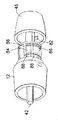
図を参照すると、末端部14および基端部16を有する本体12を有する医療用注射器10が示されている。末端部14は、使用中、患者に向かうように意図されているのに対し、基端部16は、使用中、患者から離れる方向に向うように意図されている。医療用注射器10は、針アセンブリがネジ山のような何らかの既知の方法で取り付けられ得る機構18を含んでいる。
Referring to the figures, a
容器20が第1および第2の混合可能な成分22、24を収容するために、本体12に配置される。少なくとも1つのストッパ26は、所定の距離を越えてストッパ26の末端方向への前進が第1および第2の混合可能な成分22、24の混合を引き起こすように構成されている容器20に関連する。そのような混合を可能にするために既知の配列が利用され得る。限定されない例として、第1および第2の混合可能な成分22、24は、補助ストッパ28により分離され得る。補助ストッパ28は、容器20を、第1および第2の混合可能な成分22、24をそれぞれ収容する第1および第2の室30、32に分離している。隔壁34は、第1の室30の末端部を封印しているのに対し、ストッパ26は、第2の室32の基端部を封印するように配置されている。乾燥成分が混合可能な成分の1つとして使用される場合、混合可能な乾燥成分は、第1の室30に配置されることが好ましい。
A
1以上のバイパス溝36が、容器20の壁に形成されている。初期状態において、図2に示されるように、補助ストッパ28は、第1および第2の室30、32の間のシールを画定し、また、第2の室32とバイパス溝36との間のシールを画定するように、バイパス溝36の基端側に少なくとも部分的に配置されている。ストッパ26が末端方向へ前進するとともに、第2の混合可能な成分24が湿っており、概略非圧縮性である場合、ストッパ26の移動の力は、第2の混合可能な成分24を介して補助ストッパ28に伝達される。補助ストッパ28が末端方向へ十分に移動すると、第2の室32は、バイパス溝36と連通状態になり、したがって、第2の混合可能な成分24は、ストッパ26の末端方向へのさらなる移動により、第1の室30内に強制的に押し込められる。図5を参照すると、ストッパ26が末端方向に十分に前進すると、第2の室32は、何もない状態、すなわち、第2の混合可能な成分24がその中に実質上全く残っていない状態に縮められる。さらに、補助ストッパ28は、第1の室30とバイパス溝36との間のシールを画定するように配置される。第1および第2の混合可能な成分22、24は、注入可能な溶液29を作り出し、注入できる状態となるように、例えば、医療用注射器10の撹拌により、第1の室30内で混合される。
One or
容器20は、バレル(a barrel)38内に画定される。バレル38は、独立した薬品カートリッジ(図2)からなるバレルであってもよいし、あるいは、医療用注射器10の一部からなるバレルであってもよい。
当業者に理解されるように、再形成を可能にする別の配列が利用され得る。さらに、3部構成などのシステムのような2部構成以上のシステムが利用され得る。治癒力のある有効成分(active medical ingredients)が第1および第2の混合可能な成分22、24のうちの一方または両方に含まれ得る。第1の混合可能な成分22は、乾燥状態(例えば、粉末または粒状物質)および/または液体状態(例えば、流動性を有する(スラリーまたは液体))であってもよい。上述したように、第2の混合可能な成分24は、液体またはスラリーのような湿った流動性を有する成分のみであることが好ましい。
As will be appreciated by those skilled in the art, other sequences that allow for remodeling may be utilized. Further, a system with two or more parts, such as a system with three parts, may be used. Active medical ingredients can be included in one or both of the first and second
管状プランジャー40が配置され、ストッパ26に係合するように構成される。プランジャー40の少なくとも一部内に延在することが好ましい摘み用柄42が設けられる。スリーブ44が摘み用柄42を覆って入れ子式に配置され、プランジャー40に係合するように構成される。摘み46は、該摘み46とともに回転可能であるように、摘み用柄42に固定される。摘み46は、本体12の外であって、基端部16の近くに配置される。
A
摘み用柄42およびスリーブ44は、摘み用柄42とスリーブ44が一緒に回転し得るように、摘み用柄42の回転がスリーブ44に伝達されることを選択的に可能にする、それらに形成された協同要素を有する。好ましい配列において、スリーブ44に形成されているスロット50に収容される突起48が摘み用柄42から突出している。突起48とスロット50との相互係合は、スリーブ44を摘み用柄42とともに回転させる。図5に示され、以下に説明されるように、スリーブ44の末端方向への移動に伴って、突起48は、スリーブ44から切り離された摘まみ用柄42の回転を可能にするために、スロット50から取り外されるように構成される。当業者に理解されるように、別の方法として、突起48がスリーブ44に形成され、スロット50が摘み用柄42に形成されてもよい。
The pick handle 42 and the
バネ52が、スリーブ44を末端方向に付勢するように設けられる。バネ52は、スリーブ肩部54と後面56との間で作用するように、スリーブ44を取り囲んで配置されることが好ましい。バネ52は、コイルバネすなわち圧縮バネであり得る。あるいは、当業者に理解されるように、種々の付勢要素がバネとして利用され得る。
A
図2は、バネ52により生じている運動の力に抗して第1の位置に保持されているスリーブ44を示している。バネを第1の状態に保持する解放可能な保持器58が設けられている。図3および4を参照すると、解放可能な保持器58は、スリーブ44に、好ましくはスリーブの肩部54に隣接して配置される戻り止め60および本体12に形成される溝62を含んでいる。溝62は、スリーブ44の長軸66の周囲に部分的に延在する第1の部分64を含んでいる。溝62は、また、第1の部分64から延び出し、長軸66に略平行である第2の部分68を含んでいる。溝62は、略L字形を有し得る。溝62は、戻り止め60を収容し、溝62に沿う戻り止め60の滑り運動を可能にするように形成されている。戻り止め60と溝62の配列は、本体12に配置される戻り止め60とスリーブ44に配置される溝62により入れ替えられてもよい。
FIG. 2 shows the
図3および4を参照すると、戻り止め60は、溝62の第1の部分64に嵌め込まれているように示されている。この状態で、スリーブ44は、第1の位置に保持される。摘み46を回転させると、摘み用柄42が回転させられ、次に、スリーブ44が回転させられる。そのような回転は、戻り止め60を溝62の第2の部分68内に移動させ、したがって、バネ52がスリーブ44を末端方向に前進させることを可能にする。図5に示されるように、スリーブ44は、末端方向に前進し、プランジャー42を末端方向に前進させ、次に、ストッパ26を末端方向に前進させ、したがって、第1および第2の混合可能な成分22、24を混合させる。バネ52の力の下でのスリーブ44の末端方向への移動は、スリーブの肩部54と、本体12に形成されている停止面70との相互係合および/またはバレル38との係合により制限され得る。
With reference to FIGS. 3 and 4,
成分の混合は、医療用注射器10に針が取り付けられることなしに実施されることが好ましい。そのようであるので、容器20は、混合中、抜け口がない。混合の後、針が医療用注射器10に取り付けられると、容器20内に閉じ込められていた残留ガスは、針を介して取り除かれる。プランジャー40の末端方向への前進に対する物理的停止を提供しないことが好ましいかもしれない。このようにして、混合された成分は、バネ52の力の下で最大限に圧縮され得る。医療用注射器10に針が取り付けられると、容器20は、抜け口ができ、プランジャー40の末端方向へのさらなる前進を可能にする。この二次的末端方向への前進は、使用のための針の準備を助ける。
The mixing of the components is preferably performed without the needle being attached to the
一旦混合されると、医療用注射器10により投与される投与量が調整され得る。図6を参照すると、摘み用柄42には、複数の軸方向および円周方向に間隔を介して配置される当接面72が設けられている。当接面72は、種々の管理可能な投与量に対応している。係合面74がプランジャー40に画定されている。摘み用柄42の回転は、当接面72の放射状の移動を引き起こす。当接面72は、当接面72の少なくとも1つが、摘み用柄42の末端方向への十分な移動により、係合面74に係合し、プランジャー40の運動の力を伝達することが引き起こされるように、係合面74と軸方向に一線上に整列可能である。このようにして、摘み用柄42の末端方向への移動は、プランジャー40に伝達され得る。さらに、プランジャー40の運動に対応するストロークの長さは、係合面74と係合状態にある当接面72に依存して調整され得る。係合面74から当接面72までの最初の距離が大きいほど、投与されるであろう投与量は対応して小さくなる。選択された投与量にかかわらず、摘み用柄42は、注入投与中、末端方向への移動に関し、一定の長さのストロークを有することが好ましい。余分の当接面72は、摘み用柄42の末端方向への移動による空運動をより大きくし、したがって、係合面74に係合している距離をより小さくする。プランジャー40の移動の範囲は、ストッパ26の移動の範囲を決定し、したがって、注入される投与量にある容器20から押し出される注入可能な溶液29の量を決定する。
Once mixed, the dose administered by the
投与量は、投与摘み46を回転することにより選択される。投与量設定を容易にするのに、本体12および/または投与摘み46にしるしが設けられ得る。投与摘みが混合可能な成分22、24が混合される前に不注意で回転されることを防止するために、摘み用柄42は、上述したように、それらの間における相対的な回転を防止するように、スリーブ44に連結され得る。再形成とともに、スリーブ44は、それらの間の相対的回転を可能にするように、摘み用柄42から切り離され得る。さらに、図6を参照すると、プランジャー40に形成されているリブ78に対応して、溝76が摘み用柄42に形成され得る。初期状態において、図2に示されるように、リブ78は、プランジャー40と摘み用柄42との間の相対的回転を妨げるように、溝76内に嵌まり込んでいる。再形成が完了すると、プランジャー40は、リブ78を溝76から排除させるように、前進し得る。このとき、摘み用柄42は、投与量を設定するのに、自由に回転できる。あるいは、リブ78は、再形成後の状態においてさえも、溝76内に部分的に依然として嵌まり込んでいてもよい。このような構成の場合、摘み用柄42は、リブ78を溝76から排除させるために、基端方向へ移動し、したがって、その後の投与量設定を可能にする。一旦投与量が正しく設定されると、摘み46を末端方向へ前進させることにより、該投与量が投与される。
The dose is selected by rotating the
係合面74は、リブ76の基端部80に配置され得ることに留意されたい。
Note that the
摘み46は、種々の投与量設定に対応する位置において解放可能に保持されることが好ましい。このようにして、一旦投与量が設定されると、その末端方向への移動の間摘み46の回転は全くないことが好ましく、したがって、不適当な当接面72が係合面74に係合することを防ぐ。そのような配列は、特許文献3に開示されている。特許文献3に示されるように、図7を参照すると、本体12の一部に形成されている位置決め溝84と選択的に係合可能である1以上のタブ82が、摘み46に形成され得る。位置決め溝84は、仕切り86により円周方向に隔てられ、当接面72に対応するように配置されている。タブ82は、種々の投与量のサイズに対応して、摘み46の所定の放射状の位置で位置決め溝84に嵌まり込んでいる。摘み46が回転すると、タブ82は、仕切り86を迂回し、対応する位置決め溝84内に移動させられる。位置決め溝84は、摘み46の放射状の位置を維持する。
The
さらに、摘み46は、投与量が投与されるための末端方向への一定のストローク長さの前進を可能にするように、軸方向の位置に維持されることが好ましい。タブ82の軸方向の移動を制限するように、1以上の保持リブ88が位置決め溝84に沿って配置され得る。投与量が選択されると、摘み46は、保持リブ88を迂回するタブ82とともに末端方向に前進する。タブ82と保持リブ88は、摘み46の後方に向う引き込みおよび医療用注射器10の再使用を妨げるために、固定効果(a locking affect)を提供するように構成されることが好ましい。
Furthermore, the
当業者により理解されるように、本体12は、1以上の構成要素から形成されるとともに、本明細書で説明された特徴は、そのような1以上の構成要素の何れかに形成される。
As will be appreciated by those skilled in the art, the
Claims (4)
前記本体に配置される容器であって、少なくとも第1および第2の混合可能な成分、前記容器に関連する少なくとも1つのストッパを含み、所定の距離を越える該ストッパの末端方向への前進が前記混合可能な成分の混合を引き起こす容器、
前記本体に配置されるプランジャー、
前記本体に配置される摘み用柄、
前記摘み用柄とともに回転可能であるように、前記摘み用柄に固定されている摘み、
前記摘み用柄を覆って入れ子式に配置され、前記プランジャーに係合するスリーブであって、前記摘み用柄と前記スリーブは、前記摘み用柄と前記スリーブが一緒に回転し得るように、前記摘み用柄の回転が前記スリーブに伝達されることを選択的に可能にする、それらに形成される協同要素を有する前記スリーブ、
前記スリーブを末端方向に付勢するバネ、および
前記スリーブを前記バネの力に抗して第1の位置に解放可能に保持する解放可能な保持器であって、
前記本体および前記スリーブのうちの一方に形成される戻り止め、および
前記本体および前記スリーブのうちの他方に形成される溝であって、前記スリーブの長軸を部分的に取り囲んで円周方向に配置される第1の部分と、前記第1の部分から延在し、前記長軸に略平行に配置される第2の部分を有し、前記戻り止めを収容し、前記溝に沿う前記戻り止めの滑り運動を可能にする前記溝、
を含んでいる前記解放可能な保持器、
を備え、
前記スリーブは、前記第1の位置に保持されるとともに、前記戻り止めは、前記溝の前記第1の部分に配置され、および
前記摘みの回転が、前記戻り止めを前記溝の前記第2の部分内に移動させ、したがって、前記バネが前記スリーブを末端方向に移動させることを可能にし、前記スリーブの末端方向への移動は、前記プランジャーの末端方向への移動を引き起こし、該プランジャーは、前記ストッパの末端方向への移動を引き起こし、したがって、前記混合可能な成分の混合を引き起こすことを特徴とする医療用注射器。 A body having a proximal end and a distal end;
A container disposed in the body, comprising at least a first and a second miscible component, at least one stopper associated with the container, the distal advancement of the stopper over a predetermined distance being A container that causes mixing of the mixable ingredients,
A plunger disposed on the body;
A knob handle disposed on the body,
A knob fixed to the knob, so that it can rotate with the knob.
A sleeve that is telescopically disposed over the knob handle and engages the plunger, the knob handle and the sleeve such that the knob handle and the sleeve can rotate together, The sleeve having cooperating elements formed thereon that selectively allow rotation of the knob handle to be transmitted to the sleeve;
A spring that biases the sleeve in a distal direction, and a releasable retainer that releasably holds the sleeve in a first position against the force of the spring,
A detent formed on one of the main body and the sleeve, and a groove formed on the other of the main body and the sleeve, partially surrounding the longitudinal axis of the sleeve and circumferentially A first portion disposed; and a second portion extending from the first portion and disposed substantially parallel to the major axis, containing the detent and the return along the groove Said groove allowing a sliding movement of the stop,
Said releasable retainer, comprising
With
The sleeve is held in the first position, and the detent is disposed in the first portion of the groove, and rotation of the knob causes the detent to be in the second portion of the groove. Moving into the part, thus allowing the spring to move the sleeve in the distal direction, the movement of the sleeve in the distal direction causes the plunger to move in the distal direction, the plunger A medical syringe characterized in that it causes the stopper to move in the distal direction and thus causes the mixing of the mixable components.
Applications Claiming Priority (3)
| Application Number | Priority Date | Filing Date | Title |
|---|---|---|---|
| US19246608P | 2008-09-18 | 2008-09-18 | |
| US61/192,466 | 2008-09-18 | ||
| PCT/US2009/057439 WO2010033778A2 (en) | 2008-09-18 | 2009-09-18 | Medical injector with dose knob activation for automated reconstitution |
Publications (3)
| Publication Number | Publication Date |
|---|---|
| JP2012502757A JP2012502757A (en) | 2012-02-02 |
| JP2012502757A5 JP2012502757A5 (en) | 2012-10-04 |
| JP5379233B2 true JP5379233B2 (en) | 2013-12-25 |
Family
ID=42040150
Family Applications (1)
| Application Number | Title | Priority Date | Filing Date |
|---|---|---|---|
| JP2011527986A Active JP5379233B2 (en) | 2008-09-18 | 2009-09-18 | Medical syringe with dose picking trigger for automatic remodeling |
Country Status (7)
| Country | Link |
|---|---|
| US (1) | US8403883B2 (en) |
| EP (1) | EP2328639B1 (en) |
| JP (1) | JP5379233B2 (en) |
| CN (1) | CN102186521B (en) |
| DK (1) | DK2328639T3 (en) |
| ES (1) | ES2625488T3 (en) |
| WO (1) | WO2010033778A2 (en) |
Families Citing this family (31)
| Publication number | Priority date | Publication date | Assignee | Title |
|---|---|---|---|---|
| US8926558B2 (en) * | 2008-07-04 | 2015-01-06 | Shl Group Ab | Medicament delivery device with mixing mechanism |
| CN102186517B (en) | 2008-09-18 | 2013-07-24 | 贝克顿·迪金森公司 | Medical injector with ratcheting plunger |
| CN102202710B (en) * | 2008-09-18 | 2013-08-21 | 贝克顿·迪金森公司 | Medical injector with rotatable body portions |
| JP2012532177A (en) * | 2009-07-06 | 2012-12-13 | サノフィ−アベンティス・ドイチュラント・ゲゼルシャフト・ミット・ベシュレンクテル・ハフツング | Thermal and vibration stable insulin formulations |
| DK2493529T3 (en) * | 2009-10-26 | 2016-05-17 | Shl Group Ab | Drug delivery device |
| US9623184B2 (en) | 2009-12-04 | 2017-04-18 | Becton, Dickinson And Company | Cartridge for containing and dispensing a medicament |
| JP5807021B2 (en) | 2010-02-18 | 2015-11-10 | サノフィ−アベンティス・ドイチュラント・ゲゼルシャフト・ミット・ベシュレンクテル・ハフツング | Automatic syringe |
| EP2399635A1 (en) | 2010-06-28 | 2011-12-28 | Sanofi-Aventis Deutschland GmbH | Auto-injector |
| GB201012179D0 (en) * | 2010-07-20 | 2010-09-01 | Future Injection Technologies | Injection device |
| USRE48593E1 (en) | 2010-12-21 | 2021-06-15 | Sanofi-Aventis Deutschland Gmbh | Auto-injector |
| EP2468333A1 (en) | 2010-12-21 | 2012-06-27 | Sanofi-Aventis Deutschland GmbH | Auto-injector |
| EP2468330A1 (en) | 2010-12-21 | 2012-06-27 | Sanofi-Aventis Deutschland GmbH | Auto-injector |
| CN105498049B (en) * | 2011-03-17 | 2018-09-21 | 贝克顿·迪金森公司 | Medical injector with ratchet-type plunger |
| CA2745320A1 (en) * | 2011-07-06 | 2013-01-06 | Duoject Medical Systems Inc. | Reconstitution device |
| US20130085452A1 (en) * | 2011-09-30 | 2013-04-04 | Becton Dickinson France, S.A.S. | Syringe Assembly Having a Rotatably Advanceable Plunger Rod |
| US20140312074A1 (en) * | 2011-12-06 | 2014-10-23 | Novo Nordisk A/S | Drive Mechanism for an Injection Device and a Method of Assembling an Injection Device Incorporating Such Drive Mechanism |
| US9751056B2 (en) | 2012-01-23 | 2017-09-05 | Merit Medical Systems, Inc. | Mixing syringe |
| US8834449B2 (en) | 2012-01-23 | 2014-09-16 | Ikomed Technologies, Inc. | Mixing syringe |
| US9095394B2 (en) * | 2012-04-26 | 2015-08-04 | Kyphon Sarl | Cement delivering device and method |
| EP2823841A1 (en) * | 2013-07-09 | 2015-01-14 | Sanofi-Aventis Deutschland GmbH | Autoinjector |
| WO2015071123A1 (en) | 2013-11-15 | 2015-05-21 | Carebay Europe Ltd | Medicament delivery device |
| EP2923714A1 (en) | 2014-03-28 | 2015-09-30 | Sanofi-Aventis Deutschland GmbH | Autoinjector triggered by skin contact |
| US20150290078A1 (en) * | 2014-04-14 | 2015-10-15 | Massachusetts Institute Of Technology | Reconstitution of pharmaceuticals for injection |
| GB2529621B (en) * | 2014-08-21 | 2016-12-07 | Owen Mumford Ltd | Safety syringe |
| US10143625B2 (en) | 2015-03-17 | 2018-12-04 | Recon Therapeutics, Inc. | Pharmaceutical reconstitution |
| JP7076106B2 (en) | 2016-04-15 | 2022-05-27 | 参天製薬株式会社 | Precise and accurate microliter dosing syringe |
| EP3638346A1 (en) * | 2017-06-16 | 2020-04-22 | Credence Medsystems, Inc. | System and method for safety syringe |
| EP3593838A1 (en) * | 2018-07-13 | 2020-01-15 | Zyno Medical, Llc | High precision syringe with removable pump unit |
| WO2020102446A2 (en) | 2018-11-13 | 2020-05-22 | Credence Medsystems, Inc. | System and method for multiple site injection |
| WO2021097353A2 (en) * | 2019-11-14 | 2021-05-20 | Congruence Medical Solutions, Llc | Variable dosing syringe |
| WO2021257911A1 (en) | 2020-06-17 | 2021-12-23 | Credence Medsystems, Inc. | System and method for microdose injection |
Family Cites Families (14)
| Publication number | Priority date | Publication date | Assignee | Title |
|---|---|---|---|---|
| US4689042A (en) * | 1985-05-20 | 1987-08-25 | Survival Technology, Inc. | Automatic medicament ingredient mixing and injecting apparatus |
| IL86799A (en) | 1987-07-02 | 1993-03-15 | Kabi Pharmacia Ab | Method and device for injection |
| GB9223183D0 (en) * | 1992-11-05 | 1992-12-16 | Medimech Int Ltd | Improvements related to auto injectors |
| DE19821934C1 (en) * | 1998-05-15 | 1999-11-11 | Disetronic Licensing Ag | Device for the dosed administration of an injectable product |
| SE9803662D0 (en) | 1998-10-26 | 1998-10-26 | Pharmacia & Upjohn Ab | autoinjector |
| WO2000062839A2 (en) * | 1999-04-16 | 2000-10-26 | Becton Dickinson And Company | Pen style injector with automated substance combining feature |
| AU2003275895B2 (en) * | 2002-11-25 | 2009-02-05 | Tecpharma Licensing Ag | Auto-injector comprising a resettable releasing safety device |
| DE10351596B4 (en) | 2003-11-05 | 2007-10-11 | Tecpharma Licensing Ag | Autoinjector with variable dose |
| ES2412332T3 (en) * | 2004-11-24 | 2013-07-11 | Becton, Dickinson And Company | Automatic reconstitution injector device |
| CA2595069C (en) | 2005-01-18 | 2011-05-03 | Wockhardt Americas Inc | Pen shaped medication injection devices |
| US7407494B2 (en) * | 2005-01-31 | 2008-08-05 | Bostroem Anders | Device for delivering medicament |
| JP4150389B2 (en) * | 2005-09-05 | 2008-09-17 | 日本ケミカルリサーチ株式会社 | Injection device |
| JP4367653B2 (en) * | 2006-05-23 | 2009-11-18 | 前田産業株式会社 | Prefilled syringe holder and syringe |
| ATE473772T1 (en) * | 2007-01-17 | 2010-07-15 | Shl Group Ab | DEVICE FOR DISPENSING MEDICATIONS |
-
2009
- 2009-09-18 WO PCT/US2009/057439 patent/WO2010033778A2/en active Application Filing
- 2009-09-18 EP EP09815250.7A patent/EP2328639B1/en active Active
- 2009-09-18 ES ES09815250.7T patent/ES2625488T3/en active Active
- 2009-09-18 JP JP2011527986A patent/JP5379233B2/en active Active
- 2009-09-18 US US13/119,014 patent/US8403883B2/en active Active
- 2009-09-18 DK DK09815250.7T patent/DK2328639T3/en active
- 2009-09-18 CN CN2009801415131A patent/CN102186521B/en active Active
Also Published As
| Publication number | Publication date |
|---|---|
| WO2010033778A2 (en) | 2010-03-25 |
| WO2010033778A3 (en) | 2010-07-01 |
| CN102186521A (en) | 2011-09-14 |
| CN102186521B (en) | 2013-07-24 |
| US8403883B2 (en) | 2013-03-26 |
| US20120041366A1 (en) | 2012-02-16 |
| ES2625488T3 (en) | 2017-07-19 |
| EP2328639A2 (en) | 2011-06-08 |
| EP2328639A4 (en) | 2015-01-21 |
| EP2328639B1 (en) | 2017-02-15 |
| JP2012502757A (en) | 2012-02-02 |
| DK2328639T3 (en) | 2017-05-22 |
Similar Documents
| Publication | Publication Date | Title |
|---|---|---|
| JP5379233B2 (en) | Medical syringe with dose picking trigger for automatic remodeling | |
| JP5480269B2 (en) | Medical syringe with slidable sleeve activation | |
| JP5184529B2 (en) | Block element for dosing mechanism | |
| TWI576128B (en) | Medicament delivery device | |
| US8556862B2 (en) | Needle mounting feature for ensuring proper reconstitution sequence | |
| US9132235B2 (en) | Medicament delivery device | |
| CN102186519B (en) | Medical injector with button activation | |
| JP2012502757A5 (en) | ||
| US10034980B2 (en) | Medical injector with post-autoreconstitution dose setting and autoplunger drive | |
| TWI569841B (en) | Medicament delivery device | |
| US20150094652A1 (en) | Needle mounting feature for ensuring proper reconstitution sequence |
Legal Events
| Date | Code | Title | Description |
|---|---|---|---|
| A521 | Request for written amendment filed |
Free format text: JAPANESE INTERMEDIATE CODE: A523 Effective date: 20120816 |
|
| A621 | Written request for application examination |
Free format text: JAPANESE INTERMEDIATE CODE: A621 Effective date: 20120816 |
|
| A977 | Report on retrieval |
Free format text: JAPANESE INTERMEDIATE CODE: A971007 Effective date: 20130805 |
|
| TRDD | Decision of grant or rejection written | ||
| A01 | Written decision to grant a patent or to grant a registration (utility model) |
Free format text: JAPANESE INTERMEDIATE CODE: A01 Effective date: 20130827 |
|
| A61 | First payment of annual fees (during grant procedure) |
Free format text: JAPANESE INTERMEDIATE CODE: A61 Effective date: 20130926 |
|
| R150 | Certificate of patent or registration of utility model |
Free format text: JAPANESE INTERMEDIATE CODE: R150 Ref document number: 5379233 Country of ref document: JP Free format text: JAPANESE INTERMEDIATE CODE: R150 |
|
| R250 | Receipt of annual fees |
Free format text: JAPANESE INTERMEDIATE CODE: R250 |
|
| R250 | Receipt of annual fees |
Free format text: JAPANESE INTERMEDIATE CODE: R250 |
|
| R250 | Receipt of annual fees |
Free format text: JAPANESE INTERMEDIATE CODE: R250 |
|
| R250 | Receipt of annual fees |
Free format text: JAPANESE INTERMEDIATE CODE: R250 |
|
| R250 | Receipt of annual fees |
Free format text: JAPANESE INTERMEDIATE CODE: R250 |
|
| R250 | Receipt of annual fees |
Free format text: JAPANESE INTERMEDIATE CODE: R250 |
|
| R250 | Receipt of annual fees |
Free format text: JAPANESE INTERMEDIATE CODE: R250 |
|
| R250 | Receipt of annual fees |
Free format text: JAPANESE INTERMEDIATE CODE: R250 |