JP7076106B2 - Precise and accurate microliter dosing syringe - Google Patents
Precise and accurate microliter dosing syringe Download PDFInfo
- Publication number
- JP7076106B2 JP7076106B2 JP2019505122A JP2019505122A JP7076106B2 JP 7076106 B2 JP7076106 B2 JP 7076106B2 JP 2019505122 A JP2019505122 A JP 2019505122A JP 2019505122 A JP2019505122 A JP 2019505122A JP 7076106 B2 JP7076106 B2 JP 7076106B2
- Authority
- JP
- Japan
- Prior art keywords
- plunger rod
- component
- syringe
- gear
- housing
- Prior art date
- Legal status (The legal status is an assumption and is not a legal conclusion. Google has not performed a legal analysis and makes no representation as to the accuracy of the status listed.)
- Active
Links
Images


Classifications
-
- A—HUMAN NECESSITIES
- A61—MEDICAL OR VETERINARY SCIENCE; HYGIENE
- A61M—DEVICES FOR INTRODUCING MEDIA INTO, OR ONTO, THE BODY; DEVICES FOR TRANSDUCING BODY MEDIA OR FOR TAKING MEDIA FROM THE BODY; DEVICES FOR PRODUCING OR ENDING SLEEP OR STUPOR
- A61M5/00—Devices for bringing media into the body in a subcutaneous, intra-vascular or intramuscular way; Accessories therefor, e.g. filling or cleaning devices, arm-rests
- A61M5/178—Syringes
- A61M5/31—Details
- A61M5/315—Pistons; Piston-rods; Guiding, blocking or restricting the movement of the rod or piston; Appliances on the rod for facilitating dosing ; Dosing mechanisms
- A61M5/31565—Administration mechanisms, i.e. constructional features, modes of administering a dose
- A61M5/31576—Constructional features or modes of drive mechanisms for piston rods
- A61M5/31583—Constructional features or modes of drive mechanisms for piston rods based on rotational translation, i.e. movement of piston rod is caused by relative rotation between the user activated actuator and the piston rod
- A61M5/31585—Constructional features or modes of drive mechanisms for piston rods based on rotational translation, i.e. movement of piston rod is caused by relative rotation between the user activated actuator and the piston rod performed by axially moving actuator, e.g. an injection button
-
- A—HUMAN NECESSITIES
- A61—MEDICAL OR VETERINARY SCIENCE; HYGIENE
- A61M—DEVICES FOR INTRODUCING MEDIA INTO, OR ONTO, THE BODY; DEVICES FOR TRANSDUCING BODY MEDIA OR FOR TAKING MEDIA FROM THE BODY; DEVICES FOR PRODUCING OR ENDING SLEEP OR STUPOR
- A61M5/00—Devices for bringing media into the body in a subcutaneous, intra-vascular or intramuscular way; Accessories therefor, e.g. filling or cleaning devices, arm-rests
- A61M5/178—Syringes
- A61M5/31—Details
- A61M5/315—Pistons; Piston-rods; Guiding, blocking or restricting the movement of the rod or piston; Appliances on the rod for facilitating dosing ; Dosing mechanisms
- A61M5/31533—Dosing mechanisms, i.e. setting a dose
- A61M5/31545—Setting modes for dosing
- A61M5/31548—Mechanically operated dose setting member
- A61M5/3155—Mechanically operated dose setting member by rotational movement of dose setting member, e.g. during setting or filling of a syringe
- A61M5/31551—Mechanically operated dose setting member by rotational movement of dose setting member, e.g. during setting or filling of a syringe including axial movement of dose setting member
-
- A—HUMAN NECESSITIES
- A61—MEDICAL OR VETERINARY SCIENCE; HYGIENE
- A61F—FILTERS IMPLANTABLE INTO BLOOD VESSELS; PROSTHESES; DEVICES PROVIDING PATENCY TO, OR PREVENTING COLLAPSING OF, TUBULAR STRUCTURES OF THE BODY, e.g. STENTS; ORTHOPAEDIC, NURSING OR CONTRACEPTIVE DEVICES; FOMENTATION; TREATMENT OR PROTECTION OF EYES OR EARS; BANDAGES, DRESSINGS OR ABSORBENT PADS; FIRST-AID KITS
- A61F9/00—Methods or devices for treatment of the eyes; Devices for putting-in contact lenses; Devices to correct squinting; Apparatus to guide the blind; Protective devices for the eyes, carried on the body or in the hand
- A61F9/0008—Introducing ophthalmic products into the ocular cavity or retaining products therein
-
- A—HUMAN NECESSITIES
- A61—MEDICAL OR VETERINARY SCIENCE; HYGIENE
- A61M—DEVICES FOR INTRODUCING MEDIA INTO, OR ONTO, THE BODY; DEVICES FOR TRANSDUCING BODY MEDIA OR FOR TAKING MEDIA FROM THE BODY; DEVICES FOR PRODUCING OR ENDING SLEEP OR STUPOR
- A61M37/00—Other apparatus for introducing media into the body; Percutany, i.e. introducing medicines into the body by diffusion through the skin
- A61M37/0015—Other apparatus for introducing media into the body; Percutany, i.e. introducing medicines into the body by diffusion through the skin by using microneedles
-
- A—HUMAN NECESSITIES
- A61—MEDICAL OR VETERINARY SCIENCE; HYGIENE
- A61M—DEVICES FOR INTRODUCING MEDIA INTO, OR ONTO, THE BODY; DEVICES FOR TRANSDUCING BODY MEDIA OR FOR TAKING MEDIA FROM THE BODY; DEVICES FOR PRODUCING OR ENDING SLEEP OR STUPOR
- A61M39/00—Tubes, tube connectors, tube couplings, valves, access sites or the like, specially adapted for medical use
- A61M39/10—Tube connectors; Tube couplings
-
- A—HUMAN NECESSITIES
- A61—MEDICAL OR VETERINARY SCIENCE; HYGIENE
- A61M—DEVICES FOR INTRODUCING MEDIA INTO, OR ONTO, THE BODY; DEVICES FOR TRANSDUCING BODY MEDIA OR FOR TAKING MEDIA FROM THE BODY; DEVICES FOR PRODUCING OR ENDING SLEEP OR STUPOR
- A61M5/00—Devices for bringing media into the body in a subcutaneous, intra-vascular or intramuscular way; Accessories therefor, e.g. filling or cleaning devices, arm-rests
- A61M5/178—Syringes
- A61M5/31—Details
- A61M5/3129—Syringe barrels
-
- A—HUMAN NECESSITIES
- A61—MEDICAL OR VETERINARY SCIENCE; HYGIENE
- A61M—DEVICES FOR INTRODUCING MEDIA INTO, OR ONTO, THE BODY; DEVICES FOR TRANSDUCING BODY MEDIA OR FOR TAKING MEDIA FROM THE BODY; DEVICES FOR PRODUCING OR ENDING SLEEP OR STUPOR
- A61M5/00—Devices for bringing media into the body in a subcutaneous, intra-vascular or intramuscular way; Accessories therefor, e.g. filling or cleaning devices, arm-rests
- A61M5/178—Syringes
- A61M5/31—Details
- A61M5/315—Pistons; Piston-rods; Guiding, blocking or restricting the movement of the rod or piston; Appliances on the rod for facilitating dosing ; Dosing mechanisms
- A61M5/31511—Piston or piston-rod constructions, e.g. connection of piston with piston-rod
-
- A—HUMAN NECESSITIES
- A61—MEDICAL OR VETERINARY SCIENCE; HYGIENE
- A61M—DEVICES FOR INTRODUCING MEDIA INTO, OR ONTO, THE BODY; DEVICES FOR TRANSDUCING BODY MEDIA OR FOR TAKING MEDIA FROM THE BODY; DEVICES FOR PRODUCING OR ENDING SLEEP OR STUPOR
- A61M5/00—Devices for bringing media into the body in a subcutaneous, intra-vascular or intramuscular way; Accessories therefor, e.g. filling or cleaning devices, arm-rests
- A61M5/178—Syringes
- A61M5/31—Details
- A61M5/315—Pistons; Piston-rods; Guiding, blocking or restricting the movement of the rod or piston; Appliances on the rod for facilitating dosing ; Dosing mechanisms
- A61M5/31533—Dosing mechanisms, i.e. setting a dose
- A61M5/31545—Setting modes for dosing
- A61M5/31548—Mechanically operated dose setting member
- A61M5/3155—Mechanically operated dose setting member by rotational movement of dose setting member, e.g. during setting or filling of a syringe
- A61M5/31553—Mechanically operated dose setting member by rotational movement of dose setting member, e.g. during setting or filling of a syringe without axial movement of dose setting member
-
- A—HUMAN NECESSITIES
- A61—MEDICAL OR VETERINARY SCIENCE; HYGIENE
- A61M—DEVICES FOR INTRODUCING MEDIA INTO, OR ONTO, THE BODY; DEVICES FOR TRANSDUCING BODY MEDIA OR FOR TAKING MEDIA FROM THE BODY; DEVICES FOR PRODUCING OR ENDING SLEEP OR STUPOR
- A61M5/00—Devices for bringing media into the body in a subcutaneous, intra-vascular or intramuscular way; Accessories therefor, e.g. filling or cleaning devices, arm-rests
- A61M5/178—Syringes
- A61M5/31—Details
- A61M5/315—Pistons; Piston-rods; Guiding, blocking or restricting the movement of the rod or piston; Appliances on the rod for facilitating dosing ; Dosing mechanisms
- A61M5/31533—Dosing mechanisms, i.e. setting a dose
- A61M5/31545—Setting modes for dosing
- A61M5/31548—Mechanically operated dose setting member
- A61M5/31556—Accuracy improving means
- A61M5/31558—Accuracy improving means using scaling up or down transmissions, e.g. gearbox
-
- A—HUMAN NECESSITIES
- A61—MEDICAL OR VETERINARY SCIENCE; HYGIENE
- A61M—DEVICES FOR INTRODUCING MEDIA INTO, OR ONTO, THE BODY; DEVICES FOR TRANSDUCING BODY MEDIA OR FOR TAKING MEDIA FROM THE BODY; DEVICES FOR PRODUCING OR ENDING SLEEP OR STUPOR
- A61M5/00—Devices for bringing media into the body in a subcutaneous, intra-vascular or intramuscular way; Accessories therefor, e.g. filling or cleaning devices, arm-rests
- A61M5/178—Syringes
- A61M5/31—Details
- A61M5/315—Pistons; Piston-rods; Guiding, blocking or restricting the movement of the rod or piston; Appliances on the rod for facilitating dosing ; Dosing mechanisms
- A61M5/31565—Administration mechanisms, i.e. constructional features, modes of administering a dose
- A61M5/31566—Means improving security or handling thereof
- A61M5/31573—Accuracy improving means
- A61M5/31575—Accuracy improving means using scaling up or down transmissions, e.g. gearbox
-
- A—HUMAN NECESSITIES
- A61—MEDICAL OR VETERINARY SCIENCE; HYGIENE
- A61M—DEVICES FOR INTRODUCING MEDIA INTO, OR ONTO, THE BODY; DEVICES FOR TRANSDUCING BODY MEDIA OR FOR TAKING MEDIA FROM THE BODY; DEVICES FOR PRODUCING OR ENDING SLEEP OR STUPOR
- A61M5/00—Devices for bringing media into the body in a subcutaneous, intra-vascular or intramuscular way; Accessories therefor, e.g. filling or cleaning devices, arm-rests
- A61M5/178—Syringes
- A61M5/31—Details
- A61M5/32—Needles; Details of needles pertaining to their connection with syringe or hub; Accessories for bringing the needle into, or holding the needle on, the body; Devices for protection of needles
- A61M5/34—Constructions for connecting the needle, e.g. to syringe nozzle or needle hub
-
- A—HUMAN NECESSITIES
- A61—MEDICAL OR VETERINARY SCIENCE; HYGIENE
- A61M—DEVICES FOR INTRODUCING MEDIA INTO, OR ONTO, THE BODY; DEVICES FOR TRANSDUCING BODY MEDIA OR FOR TAKING MEDIA FROM THE BODY; DEVICES FOR PRODUCING OR ENDING SLEEP OR STUPOR
- A61M5/00—Devices for bringing media into the body in a subcutaneous, intra-vascular or intramuscular way; Accessories therefor, e.g. filling or cleaning devices, arm-rests
- A61M5/178—Syringes
- A61M5/31—Details
- A61M5/3129—Syringe barrels
- A61M2005/3131—Syringe barrels specially adapted for improving sealing or sliding
-
- A—HUMAN NECESSITIES
- A61—MEDICAL OR VETERINARY SCIENCE; HYGIENE
- A61M—DEVICES FOR INTRODUCING MEDIA INTO, OR ONTO, THE BODY; DEVICES FOR TRANSDUCING BODY MEDIA OR FOR TAKING MEDIA FROM THE BODY; DEVICES FOR PRODUCING OR ENDING SLEEP OR STUPOR
- A61M5/00—Devices for bringing media into the body in a subcutaneous, intra-vascular or intramuscular way; Accessories therefor, e.g. filling or cleaning devices, arm-rests
- A61M5/178—Syringes
- A61M5/31—Details
- A61M5/3129—Syringe barrels
- A61M5/3137—Specially designed finger grip means, e.g. for easy manipulation of the syringe rod
- A61M2005/3139—Finger grips not integrally formed with the syringe barrel, e.g. using adapter with finger grips
Description
関連出願の相互参照
本出願は、2016年4月15日に出願された米国仮出願第62/323,341号(タイトル:正確で優れた精度のマイクロリットル投薬シリンジ)の優先権を主張し、参照によりその全体が本明細書に組み込まれる。
Cross-reference to related applications This application claims priority to US Provisional Application No. 62 / 323,341 (Title: Accurate and Superior Precision Microliter Dosing Syringe) filed April 15, 2016. The whole is incorporated herein by reference.
本発明は、シリンジに関し、より詳細には、マイクロリットルサイズの用量の送出が可能なシリンジに関する。 The present invention relates to syringes, and more particularly to syringes capable of delivering microliter-sized doses.
複数の研究では、標準的なシリンジが正確なマイクロリットルサイズの用量を送出できない原因となるいくつかの要因が明らかとなっている。シリンダーバレル、プランジャー(押し子)ロッド、およびプランジャーシールなどの構成要素を含むほとんどの従来のシリンジは、ミリリットルの用量を送出するように設計されており、正確かつ精度よく用量を送出できない。従来のシリンジを使用してマイクロリットルサイズの用量を送出する際の変化は、しばしば、ユーザがプランジャーロッドによる移動距離を正確に制御できないことによって引き起こされる。移動距離は、投薬の開始および投薬の終了を設定することによって制御される。いくつかの研究によれば、投薬の開始および終了をより良く定義することにより、マイクロリットルサイズの用量の送出の精度を改善できることが示されている。しかし、これは精度を保証するためには不十分である。あるユーザから別のユーザへの変動、および移動距離の限界を確実に解決するための人間の固有の限界が不正確さの原因となり得る。研究によれば、この変動は目的の用量の20%にもなることが示されている。さらに、プランジャーの移動を規定する視覚的基準と目盛りとを確立する際に、ばらつきが発生し得る製造上の問題がある。これらの変動は、ミリリットルの用量を送出する場合には無視できるが、マイクロリットルサイズの用量を送出する場合には、無視できないほどの大きな変動の原因となる。 Studies have revealed several factors that prevent standard syringes from delivering accurate microliter-sized doses. Most conventional syringes, including components such as cylinder barrels, plunger rods, and plunger seals, are designed to deliver milliliter doses and cannot deliver doses accurately and accurately. Changes in delivering microliter-sized doses using conventional syringes are often caused by the inability of the user to precisely control the distance traveled by the plunger rod. The distance traveled is controlled by setting the start and end of dosing. Several studies have shown that better definition of the start and end of dosing can improve the accuracy of delivery of microliter-sized doses. However, this is insufficient to guarantee accuracy. Inaccuracies can be caused by variations from one user to another, and human inherent limits to ensure that distance travel limits are resolved. Studies have shown that this variation can be as high as 20% of the desired dose. In addition, there are manufacturing problems that can lead to variability in establishing the visual criteria and scales that regulate the movement of the plunger. These variability are negligible when delivering milliliter doses, but cause non-negligible variability when delivering microliter size doses.
多くの臨床および非臨床用途では、マイクロリットルサイズの用量を送出する必要がある。マイクロリットルの送出のための用途には、眼の中または上への注射可能な薬物送出、細胞内送出、放射性薬物の送出、化学療法などが含まれる。正確さと高精度であることの両方が、治療窓が狭い薬物では重要であり、正確さと精度とが不十分な場合には、注射薬物の量を治療窓外に置くことになる。場合によっては、不正確さと精度の低さとが、圧力の上昇、細胞壁の破裂など、注射部位における生物物理学的特性の変化をもたらすことがある。マイクロリットルの薬物送出の場合、標準的な医薬充填仕上げシステムまたは標準的なプレフィラブルシリンジ構成要素のいずれとも適合しないシステムは不適切な場合がある。研究によれば、硝子体内投与のためには、プレフィラブルシリンジ構成要素のみを用いたマイクロリットル送出システムの使用が、最適ではない結果をもたらすことを示した。 Many clinical and non-clinical applications require delivery of microliter-sized doses. Applications for delivery of microliters include injectable drug delivery into or above the eye, intracellular delivery, radiodrug delivery, chemotherapy and the like. Both accuracy and accuracy are important for drugs with a narrow treatment window, and if accuracy and accuracy are inadequate, the amount of injectable drug will be placed outside the treatment window. In some cases, inaccuracies and inaccuracies can lead to changes in biophysical properties at the injection site, such as increased pressure and rupture of the cell wall. For microliter drug delivery, systems that are incompatible with either standard pharmaceutical fill-finish systems or standard prefillable syringe components may be inadequate. Studies have shown that the use of microliter delivery systems using only prefillable syringe components for intravitreal administration yields suboptimal results.
注射可能な物質または薬物が予め充填されているか、またはユーザが充填したかに関わらず、マイクロリットル投薬シリンジは、針または他の送出管を準備して、送出前に確実に空気が放出されていなければならない。プライミングは、一旦用量が設定された際に、確実に正確な用量を投薬するために重要である。薬物が予め充填されている(すなわち、最終ユーザによって充填されていない)場合、正確な投薬量と薬物充填の精度とを確実に切り離すために、プライミングを実施することが重要である。 Whether pre-filled with injectable material or drug or filled by the user, the microliter dosing syringe is prepared with a needle or other delivery tube to ensure that air is released prior to delivery. There must be. Priming is important to ensure that the correct dose is administered once the dose has been set. If the drug is pre-filled (ie, not filled by the end user), it is important to perform priming to ensure a separation between the correct dosage and the accuracy of the drug filling.
従来の市販のシリンジに適合可能で、正確で優れた精度のマイクロリットルサイズの用量の設定および送出機構が必要とされており、それによって従来のシリンジで正確かつ優れた精度のマイクロリットルサイズの用量の送出が可能になる。 There is a need for an accurate and highly accurate microliter size dose setting and delivery mechanism that is compatible with conventional commercial syringes, thereby providing accurate and highly accurate microliter size doses with conventional syringes. Can be sent.
いくつかの実施形態によれば、正確かつ優れた精度の投薬機構は、プレフィルド式(予め取り付けられた針、ユーザが取り付けた針、引っ込み可能な針などを含む)およびユーザ充填型を含んだ多くのシリンジ構成で構成することができる。いくつかの実施形態によれば、システムは、シリンジとは独立して製造されて部分的に組み立てられ、次いでシリンジに連結されてプランジャーロッドの機能性を提供する投薬機構を含む。従って、正確な投薬機構の機能は、従来のシリンジのプランジャーロッドの特徴に類似した特徴を含むが、改良された分解能を有するため正確で優れた精度のマイクロリットルサイズの用量送出に適した用量を設定できる。 According to some embodiments, accurate and highly accurate dosing mechanisms include many prefilled (including pre-mounted needles, user-mounted needles, retractable needles, etc.) and user-filled types. It can be configured with a syringe configuration of. According to some embodiments, the system comprises a dosing mechanism that is manufactured independently of the syringe, partially assembled, and then coupled to the syringe to provide the functionality of the plunger rod. Therefore, the function of the precise dosing mechanism includes features similar to those of the plunger rod of a conventional syringe, but with improved resolution, a dose suitable for accurate and superior precision microliter size dose delivery. Can be set.
いくつかの実施形態によれば、システムは、ラグおよび歯を備えたプランジャーロッドを含むことができる。プランジャーロッドのラグは、つまみナット内の雌ねじと機械的に相互作用することがある。プランジャーロッドの歯は、歯車列の1組の歯と噛み合うことができる。プランジャーロッドの軸方向の前進により、歯車の回転を引き起こすねじり力が発生することがある。歯車は、1つ以上の追加の歯車と連結されてもよい。追加の歯車の1つの歯は、駆動ロッドの歯と噛み合うことができる。駆動ロッドは、プレフィルドシリンジバレル内に配置されてもよく、プランジャーアダプターに隣接してもよい。プランジャーアダプターは、プランジャーシールの後部にねじ込まれてもよい。つまみナットと歯車列はすべてハウジング内に配置されている。歯車は、その幾何学的中心のピンを介してハウジングに取り付けられてもよい。シリンジバレルのフランジは、ハウジング内に配置されてもよく、カバーがハウジングと嵌合して、投薬機構をシリンジに結合してもよい。 According to some embodiments, the system can include a plunger rod with lugs and teeth. The lugs on the plunger rod may interact mechanically with the female thread in the knob nut. The teeth of the plunger rod can mesh with a set of teeth in the gear train. Axial advancement of the plunger rod may generate a torsional force that causes the gear to rotate. Gears may be coupled with one or more additional gears. One tooth of the additional gear can mesh with the tooth of the drive rod. The drive rod may be located within the prefilled syringe barrel or may be adjacent to the plunger adapter. The plunger adapter may be screwed into the rear of the plunger seal. The knob nuts and gear trains are all located inside the housing. The gear may be attached to the housing via a pin at its geometric center. The flange of the syringe barrel may be located within the housing or the cover may fit into the housing to connect the dosing mechanism to the syringe.
いくつかの実施形態によれば、シリンジ用のプランジャーロッドアセンブリは、第1の線形歯車を含む第1プランジャーロッド構成要素と、第2の線形歯車を含む第2プランジャーロッド構成要素と、第1の線形歯車と噛み合う複数の歯を有する第1の回転歯車と、第2の線形歯車と噛み合う第2の複数の歯を有する第2の回転歯車とを備え、上記第1の回転歯車は、第1プランジャーロッド構成要素の並進移動により第2プランジャーロッド構成要素が並進移動するように第2の回転歯車に連結されている。 According to some embodiments, the plunger rod assembly for the syringe comprises a first plunger rod component comprising a first linear gear and a second plunger rod component comprising a second linear gear. The first rotary gear comprises a first rotary gear having a plurality of teeth that mesh with the first linear gear and a second rotary gear having a second plurality of teeth that mesh with the second linear gear. , The second plunger rod component is connected to the second rotary gear so as to be translated by the translational movement of the first plunger rod component.
これらの実施形態のいずれにおいても、第1プランジャーロッド構成要素の第1量の移動により、第2プランジャーロッド構成要素が、第1の量よりも少ない第2の量の並進移動ができる。これらの実施形態のいずれにおいても、第1の回転歯車および第2の回転歯車は、複合歯車の一部であってもよい。 In any of these embodiments, the movement of the first quantity of the first plunger rod component allows the second plunger rod component to be translated by a second amount less than the first quantity. In any of these embodiments, the first rotary gear and the second rotary gear may be part of a composite gear.
これらの実施形態のいずれにおいても、第1の回転歯車は、第2の回転歯車から離間していてもよい。これらの実施形態のいずれにおいても、第1および第2の回転歯車は、第3の回転歯車によって離間していてもよい。これらの実施形態のいずれにおいても、第2および第3の回転歯車は、複合歯車であってもよい。 In any of these embodiments, the first rotary gear may be separated from the second rotary gear. In any of these embodiments, the first and second rotary gears may be separated by a third rotary gear. In any of these embodiments, the second and third rotary gears may be compound gears.
これらの実施形態のいずれにおいても、第1の組の歯は、第1のピッチ円直径を有し、第2の組の歯は第1のピッチ円直径とは異なる第2のピッチ円直径を有することができる。これらの実施形態のいずれにおいても、第1のピッチ円直径は第2のピッチ円直径より大きくてもよい。 In any of these embodiments, the first set of teeth has a first pitch circle diameter and the second set of teeth has a second pitch circle diameter that is different from the first pitch circle diameter. Can have. In any of these embodiments, the first pitch circle diameter may be larger than the second pitch circle diameter.
これらの実施形態のいずれにおいても、第1の組および第2の組の歯の内の少なくとも1つは、インボリュート歯を含むことができる。これらの実施形態のいずれにおいても、第1および第2プランジャーロッド構成要素は、シリンジバレル内に少なくとも部分的に挿入されるために構成されてもよい。これらの実施形態のいずれにおいても、第1プランジャーロッド構成要素の少なくとも一部は、半円形断面を含み、第2プランジャーロッド構成要素の少なくとも一部は、相補的な半円形断面を含むことができる。これらの実施形態のいずれにおいても、第1プランジャーロッド構成要素は、少なくとも1つの突出部を含むことができ、アセンブリは、少なくとも1つの突出部と係合するための回転構成要素をさらに含むことができる。 In any of these embodiments, at least one of the first and second sets of teeth can include involute teeth. In any of these embodiments, the first and second plunger rod components may be configured for at least partial insertion into the syringe barrel. In any of these embodiments, at least a portion of the first plunger rod component comprises a semi-circular cross section and at least a portion of the second plunger rod component comprises a complementary semi-circular cross section. Can be done. In any of these embodiments, the first plunger rod component may include at least one protrusion and the assembly further comprises a rotational component to engage with at least one protrusion. Can be done.
これらの実施形態のいずれにおいても、第1プランジャーロッド構成要素は、回転構成要素が少なくとも1つの突出部の少なくとも1つと係合するとき、回転構成要素の回転に応じて、軸方向に並進移動するように構成されてもよい。いずれの場合でも、第1プランジャーロッド構成要素は、回転構成要素が少なくとも1つの突出部から外れた後に、第1プランジャーロッド構成要素に直接加えられた軸方向成分を有する力に応じて軸方向に並進移動するように構成されてもよい。 In any of these embodiments, the first plunger rod component moves axially in response to the rotation of the rotating component when the rotating component engages at least one of the at least one protrusion. It may be configured to do so. In either case, the first plunger rod component is axial depending on the force having the axial component applied directly to the first plunger rod component after the rotational component has disengaged from at least one protrusion. It may be configured to translate in a direction.
これらの実施形態のいずれにおいても、回転構成要素は、少なくとも1つの突出部に係合するための雌ねじを含むことができる。これらの実施形態のいずれにおいても、回転構成要素は、プランジャーロッド構成要素が回転構成要素に対して軸方向位置に達するときに、少なくとも1つの突出部の1つに係合する少なくとも1つの止め具を含むことができる。これらの実施形態のいずれにおいても、アセンブリは、回転構成要素の一方向の回転を防止できるように、回転構成要素と係合される少なくとも1つのラチェット構成要素を含むことができる。これらの実施形態のいずれにおいても、アセンブリは、回転構成要素が第2の方向よりも第1の方向に自由度の高い回転ができるように、回転構成要素と係合する少なくとも1つのラチェット構成要素を含むことができる。 In any of these embodiments, the rotating component can include a female screw for engaging with at least one protrusion. In any of these embodiments, the rotational component is at least one stop that engages one of at least one protrusion when the plunger rod component reaches an axial position with respect to the rotational component. Can include ingredients. In any of these embodiments, the assembly may include at least one ratchet component that is engaged with the rotation component so as to prevent one-way rotation of the rotation component. In any of these embodiments, the assembly is at least one ratchet component that engages the rotation component so that the rotation component can rotate more freely in the first direction than in the second direction. Can be included.
これらの実施形態のいずれにおいても、アセンブリは、シリンジバレルの端部に取り付けるためのハウジングを含むことができる。これらの実施形態のいずれかにおいて、アセンブリは、プランジャーロッドアセンブリをシリンジバレルの端部に取り付けるために、ハウジングおよびシリンジバレルの端部と係合するための固定装置を含むことができる。これらの実施形態のいずれにおいても、固定装置は、ハウジングに固定することができる。これらの実施形態のいずれにおいても、固定装置は、ハウジングの凹部内の雌ねじまたは溝と係合することができる。これらの実施形態のいずれかにおいて、第1プランジャーロッド構成要素は、ハウジング内の開口部を通って延在し、開口部の周囲は、第1プランジャーロッド構成要素の回転を防止するために、第1プランジャーロッド構成要素と係合できる。 In any of these embodiments, the assembly can include a housing for attachment to the end of the syringe barrel. In any of these embodiments, the assembly can include a housing and a fixing device for engaging with the end of the syringe barrel in order to attach the plunger rod assembly to the end of the syringe barrel. In any of these embodiments, the fixing device can be fixed to the housing. In any of these embodiments, the fixing device can engage a female thread or groove in the recess of the housing. In any of these embodiments, the first plunger rod component extends through an opening in the housing and the perimeter of the opening is to prevent rotation of the first plunger rod component. , Can engage with the first plunger rod component.
いくつかの実施形態によれば、シリンジはバレルと、送出管と、バレル内に配置された、エラストマーまたはエラストマーを含有したプランジャーシールと、上記バレルの端部に固定されたプランジャーロッドアセンブリと、を備え、上記プランジャーロッドアセンブリは、第1の線形歯車を含む第1プランジャーロッド構成要素と、上記バレル内に少なくとも部分的に配置され、上記プランジャーシールと係合する第2プランジャーロッド構成要素と、第2の線形歯車と、第1の線形歯車に噛み合う複数の歯を有する第1の回転歯車と、第2の線形歯車に噛み合う第2の複数の歯を有する第2の回転歯車と、を備え、第1の回転歯車は、第1プランジャーロッド構成要素の並進移動により第2プランジャーロッド構成要素が並進移動するように第2の回転歯車に連結されている。 According to some embodiments, the syringe comprises a barrel, a delivery tube, an elastomer or a plunger seal containing an elastomer placed within the barrel, and a plunger rod assembly secured to the end of the barrel. The plunger rod assembly comprises a first plunger rod component including a first linear gear and a second plunger that is at least partially located within the barrel and engages the plunger seal. A rod component, a second linear gear, a first rotary gear with a plurality of teeth meshing with the first linear gear, and a second rotation with a second plurality of teeth meshing with the second linear gear. A gear is provided, and the first rotary gear is connected to the second rotary gear so that the second plunger rod component is translated by the translational movement of the first plunger rod component.
これらの実施形態のいずれにおいても、第1プランジャーロッド構成要素が、軸方向に第1の量の並進移動をすることにより、第2プランジャーロッド構成要素が、軸方向に第1の量よりも少ない第2の量の並進移動ができる。これらの実施形態のいずれにおいても、第1の回転歯車および第2の回転歯車は、複合歯車の一部であってもよい。 In any of these embodiments, the first plunger rod component undergoes a first amount of translational movement in the axial direction so that the second plunger rod component is axially more than the first quantity. A second amount of translational movement is possible. In any of these embodiments, the first rotary gear and the second rotary gear may be part of a composite gear.
これらの実施形態のいずれにおいても、第1の回転歯車は、第2の回転歯車から離間していてもよい。これらの実施形態のいずれにおいても、第1の回転歯車および第2の回転歯車は、第3の回転歯車によって離間されていてもよい。これらの実施形態のいずれにおいても、第2および第3の回転歯車は、複合歯車であってもよい。 In any of these embodiments, the first rotary gear may be separated from the second rotary gear. In any of these embodiments, the first rotary gear and the second rotary gear may be separated by a third rotary gear. In any of these embodiments, the second and third rotary gears may be compound gears.
これらの実施形態のいずれにおいても、第1の組の歯は、第1のピッチ円直径を有し、第2の組の歯は、第1のピッチ円直径とは異なる第2のピッチ円直径を有することができる。これらの実施形態のいずれにおいても、第1のピッチ円直径は、第2のピッチ円直径より大きくてもよい。 In any of these embodiments, the first set of teeth has a first pitch circle diameter and the second set of teeth has a second pitch circle diameter that is different from the first pitch circle diameter. Can have. In any of these embodiments, the first pitch circle diameter may be larger than the second pitch circle diameter.
これらの実施形態のいずれにおいても、第1の組および第2の組の歯の少なくとも1つは、インボリュート歯を含むことができる。これらの実施形態のいずれにおいても、第1および第2プランジャーロッド構成要素は、シリンジバレル内に少なくとも部分的に挿入されるために構成されてもよい。これらの実施形態のいずれにおいても、第1プランジャーロッド構成要素の少なくとも一部は、半円形断面を含み、第2プランジャーロッド構成要素の少なくとも一部は、相補的な半円形断面を含むことができる。いくつかの実施形態では、第1プランジャーロッド構成要素は、少なくとも1つの突出部を含むことができ、アセンブリは、少なくとも1つの突出部と係合するための回転構成要素をさらに含むことができる。 In any of these embodiments, at least one of the first and second sets of teeth can include involute teeth. In any of these embodiments, the first and second plunger rod components may be configured for at least partial insertion into the syringe barrel. In any of these embodiments, at least a portion of the first plunger rod component comprises a semi-circular cross section and at least a portion of the second plunger rod component comprises a complementary semi-circular cross section. Can be done. In some embodiments, the first plunger rod component may include at least one protrusion and the assembly may further include a rotational component for engaging with at least one protrusion. ..
これらの実施形態のいずれにおいても、第1プランジャーロッド構成要素は、第2の回転構成要素が少なくとも1つの突出部の少なくとも1つと係合するとき、回転構成要素の回転に応じて軸方向に並進移動するように構成されてもよい。これらの実施形態のいずれの場合でも第1プランジャーロッド構成要素は、回転構成要素が少なくとも1つの突出部から外れた後に、第1プランジャーロッド構成要素に直接加えられた軸方向成分を有する力に応じて軸方向に並進移動するように構成されてもよい。 In any of these embodiments, the first plunger rod component is axially associated with the rotation of the rotating component when the second rotating component engages at least one of the at least one protrusion. It may be configured to move in translation. In any of these embodiments, the first plunger rod component is a force having an axial component applied directly to the first plunger rod component after the rotational component has disengaged from at least one protrusion. It may be configured to translate in the axial direction according to the above.
これらの実施形態のいずれにおいても、回転構成要素は、少なくとも1つの突出部に係合するための雌ねじを含むことができる。これらの実施形態のいずれにおいても、回転構成要素は、プランジャーロッド構成要素が回転構成要素に対して軸方向位置に達するときに、少なくとも1つの突出部の1つに係合する少なくとも1つの止め具を含むことができる。これらの実施形態のいずれにおいても、アセンブリは、回転構成要素が一方向への回転を防止できるように、回転構成要素と係合する少なくとも1つのラチェット構成要素を含むことができる。これらの実施形態のいずれにおいても、アセンブリは、回転構成要素が第2の方向よりも第1の方向に自由度の高い回転ができるように、回転構成要素と係合する少なくとも1つのラチェット構成要素を含むことができる。これらの実施形態のいずれにおいても、アセンブリは、バレルの端部に取り付けられたハウジングを含むことができる。 In any of these embodiments, the rotating component can include a female screw for engaging with at least one protrusion. In any of these embodiments, the rotational component is at least one stop that engages one of at least one protrusion when the plunger rod component reaches an axial position with respect to the rotational component. Can include ingredients. In any of these embodiments, the assembly may include at least one ratchet component that engages the rotation component so that the rotation component can be prevented from rotating in one direction. In any of these embodiments, the assembly is at least one ratchet component that engages the rotation component so that the rotation component can rotate more freely in the first direction than in the second direction. Can be included. In any of these embodiments, the assembly can include a housing attached to the end of the barrel.
これらの実施形態のいずれにおいても、アセンブリは、プランジャーロッドアセンブリをシリンジバレルの端部に固定するために、ハウジングおよびバレルの端部と係合する固定装置を含むことができる。これらの実施形態のいずれにおいても、固定装置は、ハウジングに固定することができる。これらの実施形態のいずれにおいても、固定装置は、ハウジングの凹部内の雌ねじまたは溝と係合することができる。これらの実施形態のいずれかにおいて、第1プランジャーロッド構成要素は、ハウジング内の開口部を通って延在し、開口部の周囲は、第1プランジャーロッド構成要素の回転を防止するために、第1プランジャーロッド構成要素と係合できる。これらの実施形態のいずれにおいても、シリンジは、プレフィルドシリンジまたはプレフィラブルシリンジであってもよい。 In any of these embodiments, the assembly can include a housing and a fixing device that engages the end of the barrel to secure the plunger rod assembly to the end of the syringe barrel. In any of these embodiments, the fixing device can be fixed to the housing. In any of these embodiments, the fixing device can engage a female thread or groove in the recess of the housing. In any of these embodiments, the first plunger rod component extends through an opening in the housing and the perimeter of the opening is to prevent rotation of the first plunger rod component. , Can engage with the first plunger rod component. In any of these embodiments, the syringe may be a prefilled syringe or a prefillable syringe.
これらの実施形態のいずれにおいても、送出管は、取り付けられた針、取り付け可能な針、IVコネクタ、取り付け可能なチューブコネクタ、または取り付け可能なマイクロニードルアレイを含むことができる。これらの実施形態のいずれにおいても、プランジャーシールは、第2プランジャーロッド構成要素と係合するためのアダプターを含むことができる。 In any of these embodiments, the delivery tube can include an attached needle, an attachable needle, an IV connector, an attachable tube connector, or an attachable microneedle array. In any of these embodiments, the plunger seal may include an adapter for engaging with a second plunger rod component.
いくつかの実施形態によれば、シリンジのためのプランジャーロッドアセンブリは、第1プランジャーロッド構成要素と、第1プランジャーロッド構成要素に対して並進移動するように構成された第2プランジャーロッド構成要素と、を備え、上記第2プランジャーロッド構成要素は、第1プランジャーロッド構成要素の並進移動に応じて第2の第2プランジャーロッド構成要素が並進移動するように第1プランジャーロッド構成要素と係合する。 According to some embodiments, the plunger rod assembly for the syringe has a first plunger rod component and a second plunger configured to translate with respect to the first plunger rod component. The second plunger rod component comprises a rod component, and the first plan is such that the second second plunger rod component moves in translation in accordance with the translational movement of the first plunger rod component. Engage with the jar rod component.
これらの実施形態のいずれにおいても、第2プランジャーロッド構成要素は、少なくとも1つの回転歯車を介して第1プランジャーロッド構成要素と係合することができる。いずれの場合でも第1プランジャーロッド構成要素は、第1の線形歯車を含むことができる。第2プランジャーロッド構成要素は、第2の線形歯車を含むことができる。上記少なくとも1つの回転歯車は、上記第1の線形歯車と噛み合う、第1の組の歯を有する第1の歯車と、上記第2の線形歯車と噛み合う、第2の組の歯を有する第2の歯車とを含む。 In any of these embodiments, the second plunger rod component can engage the first plunger rod component via at least one rotary gear. In either case, the first plunger rod component may include a first linear gear. The second plunger rod component can include a second linear gear. The at least one rotary gear has a first gear having a first set of teeth that meshes with the first linear gear and a second gear having a second set of teeth that meshes with the second linear gear. Including gears.
これらの実施形態のいずれにおいても、第1の歯車および第2の歯車は、複合歯車の一部であってもよい。これらの実施形態のいずれにおいても、第1の歯車は第2の歯車から離間していてもよい。これらの実施形態のいずれにおいても、アセンブリは、回転構成要素の回転により第1プランジャーロッド構成要素の軸方向に並進移動するように第1プランジャーロッド構成要素と係合して構成された回転構成要素をさらに含むことができる。 In any of these embodiments, the first gear and the second gear may be part of a composite gear. In any of these embodiments, the first gear may be separated from the second gear. In any of these embodiments, the assembly is configured to engage the first plunger rod component so that it translates in the axial direction of the first plunger rod component by the rotation of the rotation component. Further components can be included.
これらの実施形態のいずれにおいても、回転構成要素は、第1プランジャーロッド構成要素上の1つ以上の突出部と係合するための雌ねじを含むことができる。これらの実施形態のいずれかにおいて、第2プランジャーロッド構成要素は、第1プランジャーロッド構成要素の第1の量に応じて、軸方向に第1の量より大きい第2の量の並進移動するように第1プランジャーロッド構成要素と係合する。 In any of these embodiments, the rotational component can include a female thread for engaging with one or more protrusions on the first plunger rod component. In any of these embodiments, the second plunger rod component is axially translated by a second amount greater than the first amount, depending on the first amount of the first plunger rod component. Engage with the first plunger rod component so as to.
これらの実施形態のいずれにおいても、アセンブリは、回転構成要素と係合される少なくとも1つのラチェットまたはラチェット構成要素を含むことができるため、回転構成要素の一方向の回転を防止できる。これらの実施形態のいずれにおいても、アセンブリは、回転構成要素が第2の方向よりも第1の方向に自由度の高い回転ができるように、回転構成要素と係合する少なくとも1つのラチェット構成要素を含むことができる。これらの実施形態のいずれにおいても、アセンブリは、シリンジバレルの非患者側の端部に取り付けるためのハウジングを含むことができる。これらの実施形態のいずれかにおいて、アセンブリは、プランジャーロッドアセンブリをシリンジバレルの非患者側の端部に取り付けるために、ハウジングおよびシリンジバレルの非患者側の端部と係合するための固定装置を含むことができる。 In any of these embodiments, the assembly can include at least one ratchet or ratchet component that is engaged with the rotating component, thus preventing one-way rotation of the rotating component. In any of these embodiments, the assembly is at least one ratchet component that engages the rotation component so that the rotation component can rotate more freely in the first direction than in the second direction. Can be included. In any of these embodiments, the assembly can include a housing for attachment to the non-patient end of the syringe barrel. In one of these embodiments, the assembly is a fastening device for engaging the housing and the non-patient end of the syringe barrel to attach the plunger rod assembly to the non-patient end of the syringe barrel. Can be included.
これらの実施形態のいずれにおいても、第1プランジャーロッド構成要素は、ハウジング内の開口を通って延在してもよく、開口の周囲は、第1プランジャーロッド構成要素の回転を防止するように形成されてもよい。 In any of these embodiments, the first plunger rod component may extend through an opening in the housing so that the perimeter of the opening prevents rotation of the first plunger rod component. May be formed in.
いくつかの実施形態によれば、シリンジは、バレルと、送出管と、に配置されたプランジャーシールと、バレルの端部に取り付けられたプランジャーロッドアセンブリとを、備え、プランジャーロッドアセンブリは、第1プランジャーロッド構成要素と、バレル内部に少なくとも部分的に配置され、かつプランジャーシールと係合している第2プランジャーロッド構成要素とを備え、第2プランジャーロッド構成要素は、第1プランジャーロッド構成要素に対して軸方向に並進移動するように構成されており、第1プランジャーロッド構成要素の並進移動に応じて第2プランジャーロッド構成要素が、軸方向に並進移動するように第1プランジャーロッド構成要素と噛合する。これらの実施形態のいずれにおいても、第2プランジャーロッド構成要素は、少なくとも1つの回転歯車を介して第1プランジャーロッド構成要素と係合することができる。いずれの場合でも第1プランジャーロッド構成要素は、第1の線形歯車を含むことができ、第2プランジャーロッド構成要素は、第2の線形歯車を含むことができ、少なくとも1つの回転歯車は、第1の線形歯車と噛み合う第1の組の歯を有する第1の歯車と、第2の線形歯車と噛み合う第2の組の歯を有する第2の歯車とを含む。 According to some embodiments, the syringe comprises a plunger seal located in a barrel, a delivery tube, and a plunger rod assembly attached to the end of the barrel, the plunger rod assembly. The second plunger rod component comprises a first plunger rod component and a second plunger rod component that is at least partially located within the barrel and is engaged with the plunger seal. It is configured to translate axially with respect to the first plunger rod component, and the second plunger rod component translates axially in response to the translational movement of the first plunger rod component. It meshes with the first plunger rod component so as to. In any of these embodiments, the second plunger rod component can engage the first plunger rod component via at least one rotary gear. In either case, the first plunger rod component can include a first linear gear, the second plunger rod component can include a second linear gear, and at least one rotary gear. Includes a first gear with a first set of teeth that meshes with a first linear gear and a second gear with a second set of teeth that meshes with a second linear gear.
これらの実施形態のいずれにおいても、第1の歯車および第2の歯車は、複合歯車の一部であってもよい。これらの実施形態のいずれにおいても、第1の歯車は第2の歯車から離間していてもよい。これらの実施形態のいずれにおいても、シリンジは、第1のプランジャー構成要素と係合するように構成された回転構成要素をさらに含むことができることで、回転構成要素の回転により第1プランジャーロッド構成要素が軸方向に並進移動する。これらの実施形態のいずれにおいても、回転構成要素は、第1プランジャーロッド構成要素上の1つ以上の突出部と係合するための雌ねじを含むことができる。 In any of these embodiments, the first gear and the second gear may be part of a composite gear. In any of these embodiments, the first gear may be separated from the second gear. In any of these embodiments, the syringe can further include a rotating component configured to engage the first plunger component, thereby the rotation of the rotating component to cause the first plunger rod. The components translate in the axial direction. In any of these embodiments, the rotational component can include a female thread for engaging with one or more protrusions on the first plunger rod component.
これらの実施形態のいずれかにおいて、第2プランジャーロッド構成要素は、第1プランジャーロッド構成要素の第1の量より大きい第2の量の並進移動に応じて、第2プランジャーロッド構成要素が第1の量の並進移動をするように第1プランジャーロッド構成要素と係合する。これらの実施形態のいずれにおいても、アセンブリは、回転構成要素の一方向の回転を防止するように、回転構成要素と係合される少なくとも1つのラチェット構成要素を含むことができる。これらの実施形態のいずれにおいても、アセンブリは、回転構成要素が第2の方向よりも第1の方向に自由度の高い回転ができるように回転構成要素と係合する少なくとも1つのラチェット構成要素を含むことができる。 In any of these embodiments, the second plunger rod component is a second plunger rod component in response to a second amount of translational movement that is greater than the first amount of the first plunger rod component. Engages the first plunger rod component to make a first amount of translational movement. In any of these embodiments, the assembly may include at least one ratchet component that is engaged with the rotation component to prevent one-way rotation of the rotation component. In any of these embodiments, the assembly comprises at least one ratchet component that engages the rotation component to allow more flexible rotation in the first direction than in the second direction. Can include.
これらの実施形態のいずれにおいても、アセンブリは、バレルの端部に取り付けられたハウジングを含むことができる。これらの実施形態のいずれにおいても、アセンブリは、プランジャーロッドアセンブリをシリンジバレルの端部に固定するために、ハウジングおよびバレルの端部と係合される固定装置を含むことができる。これらの実施形態のいずれにおいても、第1プランジャーロッド構成要素は、ハウジング内の開口を通って延在してもよく、開口の周囲は、第1プランジャーロッド構成要素の回転を防止するように形成されてもよい。これらの実施形態のいずれにおいても、シリンジは、プレフィルドシリンジであってもよい。 In any of these embodiments, the assembly can include a housing attached to the end of the barrel. In any of these embodiments, the assembly can include a housing and a fixing device that is engaged with the end of the barrel to secure the plunger rod assembly to the end of the syringe barrel. In any of these embodiments, the first plunger rod component may extend through an opening in the housing so that the perimeter of the opening prevents rotation of the first plunger rod component. May be formed in. In any of these embodiments, the syringe may be a prefilled syringe.
これらの実施形態のいずれにおいても、送出管は、取り付けられた針、取り付け可能な針、取り付け可能な配管コネクタ、または取り付け可能なマイクロニードルアレイを含み得る。これらの実施形態のいずれにおいても、プランジャーシールは、第2プランジャーロッド構成要素と係合するためのアダプターを含むことができる。 In any of these embodiments, the delivery tube may include an attached needle, an attachable needle, an attachable tubing connector, or an attachable microneedle array. In any of these embodiments, the plunger seal may include an adapter for engaging with a second plunger rod component.
いくつかの実施形態によれば、ブリスターパックは、シリンジがEtO、H2O2、NO2または気化過酢酸を用いて滅菌されている、上記の実施形態のいずれかによるプレフィルドシリンジを含む。 According to some embodiments, the blister pack comprises a prefilled syringe according to any of the above embodiments, wherein the syringe is sterilized with EtO, H2O2 , NO2 or vaporized peracetic acid .
これらの実施形態のいずれにおいても、シリンジの外面は、最大で1ppmのEtO、H2O2、NO2または気化過酢酸を含むことができる。これらの実施形態のいずれにおいても、シリンジの外側およびブリスターパックの内側の全EtO、H2O2、NO2または気化過酢酸残留物は、最大で0.1mgであってもよい。これらの実施形態のいずれにおいても、シリンジは、少なくとも10-6の滅菌保証レベルで滅菌されていてもよい。 In any of these embodiments, the outer surface of the syringe can contain up to 1 ppm of EtO, H2O2, NO2 or vaporized peracetic acid . In any of these embodiments, the total EtO, H2O2, NO2 or vaporized peracetic acid residue on the outside of the syringe and inside the blister pack may be up to 0.1 mg. In any of these embodiments, the syringe may be sterile at a guaranteed level of at least 10-6 .
いくつかの実施形態によれば、上記実施形態のいずれかによるシリンジを使用して用量を送出する方法は、シリンジの送出管をバレルに対して上方に向けるステップと、回転構成要素を回転させることによってバレル内でプランジャーシールを前進させるステップと、回転構成要素が第1プランジャーロッドから外れるまで回転構成要素を回転させ続けて用量を設定するステップと、回転構成要素が第1プランジャーロッドから離脱した後、プランジャーシールを前進させるために第1プランジャーロッドの端部にユーザの力を直接加えることによって用量を送出するステップと、を含む。 According to some embodiments, the method of delivering a dose using a syringe according to any of the above embodiments is a step of directing the delivery tube of the syringe upward with respect to the barrel and rotating a rotating component. The step of advancing the plunger seal in the barrel by, and the step of continuously rotating the rotation component until the rotation component is disengaged from the first plunger rod to set the dose, and the rotation component is from the first plunger rod. After withdrawal, it comprises the step of delivering the dose by applying a user's force directly to the end of the first plunger rod to advance the plunger seal.
これらの実施形態のいずれにおいても、上記方法は、第2の回転構成要素を回転させることによってバレル内でプランジャーシールを前進させる前に針をシリンジに取り付けるステップを含むことができる。これらの実施形態のいずれにおいても、シリンジは、プレフィルドシリンジであってもよい。 In any of these embodiments, the method can include attaching the needle to the syringe before advancing the plunger seal within the barrel by rotating the second rotating component. In any of these embodiments, the syringe may be a prefilled syringe.
これらの実施形態のいずれにおいても、プレフィルドシリンジは、眼科用途に使用される薬物で充填されてもよい。これらの実施形態のいずれにおいても、10マイクロメートル以上の大きさの目に見える微粒子の数は、薬物溶液1ミリリットル当たり50個未満であってもよい。これらの実施形態のいずれにおいても、25マイクロメートル以上の大きさの目に見える微粒子の数は、薬物溶液1ミリリットル当たり5個未満であってもよい。これらの実施形態のいずれにおいても、50マイクロメートル以上の大きさの目に見えない微粒子の数は、薬物溶液1ミリリットル当たり2個より少なくてもよい。 In any of these embodiments, the prefilled syringe may be filled with a drug used for ophthalmic applications. In any of these embodiments, the number of visible microparticles larger than 10 micrometers may be less than 50 per milliliter of drug solution. In any of these embodiments, the number of visible particles larger than 25 micrometers may be less than 5 per milliliter of drug solution. In any of these embodiments, the number of invisible particles larger than 50 micrometers may be less than two per milliliter of drug solution.
本発明は、添付の図面を参照して、単なる例として以下に説明される。
本明細書に記載されているのは、正確で優れた精度の投薬シリンジを提供するために、従来の(またはカスタムの)シリンジ本体を備えた機構を組み込んだ正確で優れた精度の投薬機構およびシステムである。いくつかの実施形態によれば、投薬機構は、ユーザの動作を、正確に制御された多成分プランジャーロッドの動きへと変換する。歯車列は、プランジャーロッド構成要素がシリンジプランジャーシールを押すことで移動する軸方向距離が、ユーザが直接関わることでプランジャーロッド構成要素が移動する軸方向距離に対して短くなるようにプランジャーロッド構成要素と結合可能である。つまみナットは、プランジャーロッド構成要素の1つと係合し、プランジャーロッド構成要素の移動距離を正確に制御する。投薬機構は、機構を従来のシリンジのプランジャーシール端部に連結するための1つ以上の機構を含むことができる。 Described herein are an accurate and highly accurate dosing mechanism incorporating a mechanism with a conventional (or custom) syringe body to provide an accurate and superiorly accurate dosing syringe. It is a system. According to some embodiments, the dosing mechanism transforms the user's movement into precisely controlled movement of the multi-component plunger rod. The gear train is planned so that the axial distance traveled by the plunger rod component by pressing the syringe plunger seal is shorter than the axial distance traveled by the plunger rod component with direct user involvement. Can be combined with jar rod components. The knob nut engages one of the plunger rod components and accurately controls the distance traveled by the plunger rod components. The dosing mechanism can include one or more mechanisms for connecting the mechanism to the plunger seal end of a conventional syringe.
以下の説明は、添付図面を参照して本開示の例示的な実施形態の理解を助けるために提供する。したがって、当業者であれば、特許請求された発明の範囲から逸脱することなく、本明細書に記載された例示的な実施形態の様々な変更および修正が可能であることを理解するであろう。また、一般によく知られている機能および構成の説明は、簡潔にするために省略する。 The following description is provided with reference to the accompanying drawings to aid in understanding the exemplary embodiments of the present disclosure. Accordingly, one of ordinary skill in the art will appreciate that various modifications and modifications of the exemplary embodiments described herein are possible without departing from the scope of the claimed invention. .. Also, commonly known features and configuration descriptions are omitted for brevity.
正確で、優れた精度の用量を送出するための機構、薬物送出シリンジ、または本発明の構成要素のあらゆる相対的位置を説明するために本明細書で使用される、用語「軸の」または「軸方向」は、通常、機構およびシリンジがその周りに配置可能な長手方向の軸「A」を指すが、必ずしも対称的である必要はない。「半径方向」という用語は、通常、軸「A」に直交するすべての方向を示す。ユーザ側の端部という用語は、通常、「U」と印した端部を示し、患者側の端部は、通常、「P」と印した端部を示す。本明細書で使用される場合、用語「ガラス」は、医薬品位の用途での使用に適した別の類似の化学的に不活性な材料を含むと理解される。医薬品位の用途での使用に適した化学的に不活性な材料とは、通常、環状オレフィンコポリマー(COC)、環状オレフィンポリマー(COP)、および薬剤プレフィラブルシリンジで使用される同等の物等の特定の非反応性ポリマーを含む(ただし特定の非反応性ポリマーに限定しない)、I型ホウケイ酸ガラス、石英を通常必要とする。これらのシリンジは、眼科用薬物として適用するために目に見えない微粒子の除去などの追加の処理が必要になる場合がある。プラスチックはまた、皮下シリンジに使用されるポリプロピレン、ポリカーボネートなどのポリマーを指す。用語「エラストマー」、「エラストマー系」または「エラストマー系材料」は、シリンジのプランジャーシールの製造に一般的に使用される。これには、特定の医薬用途として化学的不活性を与えるためにコーティングされる得るプランジャーシールも含まれる。「流体」は主に水を意味するが、ポリエチレングリコール、溶液中に懸濁した固体、溶液中の非混和性物質などの溶液を示す場合があり、ニュートンおよび非ニュートン液体も同様に示す。これらの全てはシリンジを用いて注射可能である。針を備えたシステムの安全性は、格納式の針機構または針のための外部のシース/カバーのいずれかを用いて実施された場合のものと捉えることができる。使用する針が投与用である場合、針は典型的にはステンレス鋼で作られる。当該針はまた、マイクロニードル及びマイクロニードルアレイを含む。使用される針のサイズは、直径が21Gから40G、長さが1インチまでの範囲のものが可能である。皮下、静脈内、皮内、硝子体内、眼内、脈絡膜上、結膜下、腫瘍内、細胞内、局所などで投与可能である。 The term "axis" or "axis" used herein to describe any relative position of an accurate, superiorly accurate dose delivery mechanism, drug delivery syringe, or component of the invention. "Axial" usually refers to the longitudinal axis "A" in which the mechanism and syringe can be placed around it, but it does not necessarily have to be symmetrical. The term "radial" usually refers to all directions orthogonal to the axis "A". The term user-side end usually refers to an end marked "U" and patient-side end usually refers to an end marked "P". As used herein, the term "glass" is understood to include another similar chemically inert material suitable for use in pharmaceutical-grade applications. Chemically inert materials suitable for use in pharmaceutical-grade applications are typically cyclic olefin copolymers (COCs), cyclic olefin polymers (COPs), and equivalents used in drug prefillable syringes. Type I alkene glasses, including, but not limited to, certain non-reactive polymers, are usually required. These syringes may require additional treatment, such as removal of invisible microparticles, for application as an ophthalmic drug. Plastic also refers to polymers such as polypropylene and polycarbonate used in subcutaneous syringes. The terms "elastomer", "elastomer-based" or "elastomer-based material" are commonly used in the manufacture of plunger seals for syringes. This also includes plunger seals that may be coated to provide chemical inactivity for specific pharmaceutical applications. "Fluid" primarily means water, but may refer to solutions such as polyethylene glycol, solids suspended in solution, immiscible substances in solution, and Newton and non-Newton liquids as well. All of these can be injected using a syringe. The safety of a system with a needle can be considered as if implemented using either a retractable needle mechanism or an external sheath / cover for the needle. If the needle used is for administration, the needle is typically made of stainless steel. The needle also includes a microneedle and a microneedle array. The size of the needle used can range from 21G to 40G in diameter and 1 inch in length. It can be administered subcutaneously, intravenously, intradermally, intravitreally, intraocularly, intrachoroidally, subconjunctivally, intratumorally, intracellularly, or locally.
正確で高精度で注射可能な用量を設定し送出するための機構、およびそのような機構を組み込むことが可能な薬物送出シリンジの実施形態を以下に記載する。このようなデバイスは、安全で使いやすく、審美的に魅力的であり、研究者、獣医従事者、および他の臨床実務家を含むユーザの人間工学的考察ごとに設計できる。最小限のトレーニング、または、トレーニングを要することなく、デバイスの起動、操作および処分が可能な人間工学的特徴が含まれてもよい。用量制御機構、流体送出シリンジ、およびそれぞれの構成要素の実施形態は、添付図面を参照して本明細書でさらに説明される。 A mechanism for setting and delivering an injectable dose with high accuracy and accuracy, and an embodiment of a drug delivery syringe capable of incorporating such a mechanism are described below. Such devices are safe, easy to use, aesthetically pleasing, and can be designed for each ergonomic consideration of users, including researchers, veterinarians, and other clinical practitioners. It may include ergonomic features that allow the device to be activated, operated and disposed of with minimal or no training. Embodiments of dose control mechanisms, fluid delivery syringes, and their respective components are further described herein with reference to the accompanying drawings.
図1~図3は、第1の実施形態による、正確で優れた精度の用量送出機構を組み込んだシリンジベースのシステム100を示す。システム100は、プランジャーロッドサブアセンブリ101、プレフィラブルシリンジ102、プランジャーシールアダプター103、およびカバー104を含む。カバー104は、カバー104上の雄ネジ105とハウジング106のバレル開口端上の雌ネジ107との係合によって、プランジャーロッドサブアセンブリ101に固定される。他の実施形態では、カバー104は、圧入、スナップオン機能、留め具などを含む他の手段を用いてハウジング106に固定することができる。いくつかの実施形態によれば、プレフィラブルシリンジは、ルアーロックアダプター108または針付針/予め取り付けられた針を含むことができる。いくつかの実施形態では、シリンジの代わりにカートリッジを使用することができる。いくつかの実施形態では、局所送出または鼻腔内送出を可能にする送出アダプターを使用することができる。プレフィラブルシリンジ102は、ダウコーニング360のようなシリコーンオイルでシリンジバレル109の内側を噴霧可能で、潤滑させることができる。あるいは、ダウコーニング365のようなシリコーンエマルションでスプレーすることもできる。シリンジを高温で焼成する場合、シリコーンをシリンジバレル109の内側で焼くこともできる。
1 to 3 show a syringe-based
いくつかの実施形態によれば、プランジャーロッドサブアセンブリ101は、その実施形態が図4に別個に示されているように、プランジャーロッド110および駆動ロッド112を含む多成分プランジャーロッドを含む。プランジャーロッドサブアセンブリ101はまた、ハウジング106、歯車111、駆動ロッド112、つまみナット113、およびばね114もまた含む。
According to some embodiments, the
プランジャーロッド110は、その長さの一部に沿って1組の線形歯128を含む(図5)。歯128は、歯車111上のより広いピッチの第1の組の歯118と噛み合う。歯車111は、回転可能にハウジングに固定されているが、並進移動できない。このため、プランジャーロッド110の直線移動により、歯車111が回転する。歯車111は、駆動ロッド112上の1組の線形歯124と噛み合うより狭いピッチの第2の組の歯120を有する複合歯車(図6)である。したがって、歯車111の回転により、駆動ロッド112が患者側の「P」方向に軸的に前進し、プランジャーアダプター136の非患者側の面を押すこととなる。これにより、充填された流体133が押し出され、針139(または他の構成要素)の先端を介して充填される。複合歯車の2組の歯の間のピッチの違いにより、駆動ロッド112はプランジャーロッド110よりも僅かな量だけ前進する。さらにユーザの力が、プランジャーシール132を直接的に押すのに要する力よりも少なくて済むという機械的利点がある。他の実施形態では、歯車111の構成は、より狭いピッチの歯がプランジャーロッドと相互に干渉し、より広いピッチの歯が駆動ロッドと相互に干渉するような逆の構成であってもよい。
The
プランジャーロッド110はまた、つまみナット113(図7A、図7B)の雌ねじ131と係合する複数の投薬ペグ129を含む。プランジャーロッド110の少なくとも一部は、プランジャーロッド110の回転を防止するハウジング内の相補的な開口内に嵌合する非円形断面を含むことができる。プランジャーロッド110の回転が抑制された状態で、つまみナット113の回転により、プランジャーロッド110が軸方向に移動する。投薬ペグ129と雌ねじ131との係合により、またユーザがプランジャーロッド110を押すことでプランジャーロッド110を軸方向に前進させることも防ぐ。つまみナット113の回転によるプランジャーロッド110の継続的な軸方向の前進により、つまみナット113の雌ねじ131が遠ざかるため、投薬ペグ142(プランジャーロッド110のユーザ側の端部に最も近い投薬ペグ)が最後尾に位置する。一旦遠ざかると、ユーザがプランジャーロッド110を押しても、既につまみナット113により、プランジャーロッド110の直線方向の前進を防ぐことはできない。いくつかの実施形態によれば、シリンジバレル109内のプランジャーロッド110の向きを維持する補助としてのラグ130が、プランジャーロッド110に設けられる。
The
プランジャーロッドサブアセンブリ101の組み立ては、バネ114をつまみナット113のキャビティであるシート115に配置する工程を含むことができる。歯車111は、より広いピッチの歯118の背面117がハウジング106に当接するように、円筒状のピン116を用いてハウジング106に取り付けることができる。ピン116とハウジング106の2つの穴122、123との間で干渉が生じるため、確実に回転的なスリップが起きることはない。歯車111は、ピン116の軸の周りを自由に回転できる。
Assembling the
つまみナット113の内側のばね114は、ばね114の開放側がシステムの患者側の端部「P」に面するように、開口部126を通る組立体としてハウジング106の内部で摺動可能である。ばね114は、構成部品の公差から生じる軸方向の自由な動きを低減するために、つまみナット113をハウジングに予め装填することができる。駆動ロッド112は、駆動ロッド112上の歯124がより狭いピッチの歯120と相互作用するように患者側の端部Pから挿入されてもよい。駆動ロッド112(図8Aおよび図8B)上の肩部125がハウジング106の表面に接触するとき、駆動ロッド112は、ハードストップまで完全に押し込み可能である。次いで、プランジャーロッド110は、ハウジング106内の背面キャビティ127(図9A~図9D参照)を通って挿入されると、その結果、歯128は、ユーザ側の端部「U」から離れて、より広いピッチの歯118と相互作用する。プランジャーロッド110のペグまたはラグ129は、つまみナット113の一方向の回転によりプランジャーロッド110を患者側の端部「P」の方向に前進させるように、つまみナット113の雌ねじ131と相互干渉する。ハウジング106の背面キャビティ127の形状は、プランジャーロッド110の断面と一致しており、プランジャーロッド110の回転を防止するように設計されている。プランジャーロッドサブアセンブリ101はこの段階で組み立てが完了している。
The
いくつかの実施形態によれば、プレフィルドシリンジを組み立てるために、流体133をシリンジの非患者側の端部から充填し、次に実質的にエラストマーのプランジャーシール132を非患者側の端部から患者側の端部に挿入する。これによってシリンジが充填される。プランジャーアダプター136は、適合する相補的なねじ山137を有するプランジャーシール132の後部にねじ込まれてもよい。プランジャーロッドサブアセンブリ101をこのプレフィルドシリンジに取り付けるために、プランジャーロッドサブアセンブリ101の患者側の端部「P」は、シリンジバレル109内のプレフィルドシリンジのユーザ側の端部「U」から挿入可能である。ユーザ側の端部「U」に向けられたねじ山105を有するカバー104は、ハウジング上のねじ山107と噛み合うまで、シリンジバレル109の全長にわたって摺動できる。カバーは締め付けられるまで回すことができる。これによって正確で優れた精度のシリンジを用いた投薬システム100が完全に組み立てられる。この組み立てられたシステムでは、ユーザの使用準備が整っており、二次包装の準備が整っており、および/または特定の用途に必要とされるような最終滅菌の準備が整っている。
According to some embodiments, to assemble a prefilled syringe,
この実施形態では、使用準備ができたとき、ユーザは、シリンジのルアーロックアダプター108を捻じってオンにすることにより、針139を取り付けることができる。シリンジの患者側の端部「P」を上向きに向けることによって、ユーザは、つまみナット113を回転させることで用量を設定する。溝状特徴部140は、より正確な把持及び触感を可能にするために、つまみナット113の外側湾曲表面上に設けられてもよい。つまみナット113の背面表面上のマーキング141は、ユーザが用量を設定するためのつまみナット113の回転方向を視覚的に示すことができる。つまみナット113が回転すると、雌ねじ131は、プランジャーロッド110上のペグまたはラグ129のためのガイドとして機能するため、プランジャーロッド110が前進する。
In this embodiment, when ready for use, the user can attach the
ユーザがつまみナット113を回転し続けると、用量設定ペグ142(最後のペグ)がつまみナット113内のネジ山131から出るまで、プランジャーロッド110は軸方向に「P」の方向で前進する。この時点の後では、つまみナット113をさらに回転させても、プランジャーロッド110が軸方向に並進移動せず、それ以上流体は投与されない。用量はこの時点で設定されたことになる。本構成は、図10Aおよび図10Bに示される。ユーザは、送出するため針を標的部位に挿入し、つまみレスト138の下面143がハウジング106の表面144に接触するまで、つまみレスト138をプランジャーロッド110上に押し込む。本構成は、図11Aおよび図11Bに示される。この時点で正確で精度よく用量が供給されたのでシステム100は安全に廃棄できる。
As the user continues to rotate the
図12~図15は、第2の実施形態による、正確で高精度の用量送出機構を組み込んだシリンジベースのシステム1000を示す。システム1000は、プレフィラブルシリンジ1002に連結されたプランジャーロッドサブアセンブリ1001を含む。プレフィラブルシリンジ1002は、ルアーロックアダプター1008およびプランジャーシール1032を含み得る。プレフィラブルシリンジ1002は、図示を目的として図12にキャップを備えたプレフィラブルシリンジ1002が示され、図13において針を備えたプレフィラブルシリンジ1002が示される。プランジャーシールアダプター1010は、プランジャーシール1032とプランジャーロッドサブアセンブリ1001との間で相互に干渉して機能するように、プレフィラブルシリンジ1002に設けられてもよい。
12-15 show a syringe-based
プランジャーロッドサブアセンブリ1001は、プレフィラブルシリンジのユーザ側の端部に固定される。プランジャーロッドサブアセンブリ1001は、用量送出中にプランジャーシール1032を(例えば、プランジャーシールアダプター1003を介して)駆動する駆動ロッド1012と、用量送出中にユーザが押すことによって駆動されるプランジャーロッド1010とを含む。プランジャーロッドサブアセンブリ1001はまた、ハウジング1006、ハウジングクリップ1004およびつまみナット1013を含む。システム1000の動作は、ユーザがつまみナット1013を回転させて用量を設定し、次にプランジャーロッド1010を押して用量を送出するという点でシステム100の動作と同様である。ハウジング1006は、用量設定のためにつまみナット1013の回転方向を示すインジケータ1040を含むことができる。つまみナット1013の回転による、つまみナット1013上の雌ねじとプランジャーロッド1010上の投薬ラグ1029との係合により、プランジャーロッド1010が前進する。プランジャーロッド1010の前進により、プランジャーロッド1010と駆動ロッド1012との運動を連結する歯車列を介して駆動ロッド1012が前進する。投薬ラグ1029がつまみナット1013上の雌ねじを一旦除去すると、用量が設定される。プランジャーロッド1010のユーザ側の端部をユーザが押すことでプランジャーロッド1010が完全に前進し、続いて駆動ロッド1012によってプランジャーシール1032が押されることで設定用量を吐出する。
The
図14Aは、用量設定構成システム1000を示す。プランジャーロッド1010は、投薬ラグ1029がつまみナット1013上の雌ねじを除去した点までハウジング1006内の前進を完了している。図示された実施形態では、用量表示1042(「20」)は、用量の設定完了および/または設定された上記用量の量を表示するので、ハウジング1006の側面の窓1044を通して見ることができる。図14Bは、用量送出構成システム1000を示す。ユーザがプランジャーロッド1010のつまみレスト1038を押すと、プランジャーロッド1010は、ハウジング1006に対して完全に押し下げられた位置まで前進する。プランジャーロッド1010の患者側の端部は、シリンジバレル1009内の前進を完了した。駆動ロッド1012、プランジャーシールアダプター1003、およびプランジャーシール1032は、また、以下により詳細に説明するように、歯車列の歯車が減速するため、プランジャーロッド1010よりも短い距離、シリンジバレル1009内の前進が完了している。したがって、プランジャーロッド1010の移動量「X」は、駆動ロッド1012の移動量「Y」より大きい。示された実施形態では、窓1044を介して表示される用量表示1042は、「0」である。これは、設定された用量が完全に供給を完了したことを示す。
FIG. 14A shows the dose setting
図15は、いくつかの実施形態による、シリンジバレル1009上へのプランジャーロッドサブアセンブリ1001のアセンブリを示す。プランジャーロッドサブアセンブリ1001の患者側の端部は、シリンジバレル1009のユーザ側の端部から挿入することができる。クリップ1004は、シリンジバレル1009の周りに配置される。クリップ1004は、1つまたは複数のペグまたは他の位置合わせ機能部で互いに位置合わせすることができる2つの部品で形成可能である。いくつかの実施形態では、部品は、例えば、位置合わせ機能部の締まり嵌合部を介して一緒にスナップ嵌めされる。クリップ片は、任意の適切な方法を使用して互いにねじ止めされても、互いに接着されてもよいし、または別の方法で互いに固定されてもよい。いくつかの実施形態では、クリップ1004は、システム100のカバー104のような一体部品である。クリップ1004がシリンジバレル1009の周りに配置されると、クリップ1004は、シリンジバレル1009のユーザ側の端部に向かって摺動し、ハウジング1006の開出端部と相互作用する。クリップ1004は、タブ1046が溝1048に一旦係合すると、回転クリップ1004(例えば、4分の1回転)がハウジング1006、シリンジバレル1009、及びクリップ1004を一緒に係止するように、ハウジング1006の患者側の内面の溝1048と係合する1つ以上のタブ1046を含むことができる。いくつかの実施形態では、クリップ1004は、ハウジング上の雌ねじと噛み合う雄ねじを含む(例えば、上述のシステム100と同様)。いくつかの実施形態では、クリップ1004は、ハウジング1006内でクリップ1004を回転させるために、スパナレンチのようなツールを挿入できる1つ以上の凹部を含む。いくつかの実施形態では、1つ以上のクリップ1004およびハウジング1006の弾性(コンプライアンス)により(例えば、タブ1046の弾性)、一旦クリップ1004がハウジング1006内に締め付けられると、ハウジング、カバーおよびシリンジバレルがプレロードされる。これによって構成要素間の自由な動きを除去する。いくつかの実施形態では、弾性を有する構成要素(波形ばね、コイルバネ、ガスケットなど)が、シリンジバレルとハウジングとの係合部をプレロードするために含まれている。
FIG. 15 shows the assembly of the
図16Aおよび図16Bは、いくつかの実施形態による、プランジャーロッド1010および駆動ロッド1012を連結する歯車列1011を示す。歯車列1011は、回転歯車1060と、より弱い力の歯車1062と、より強い力の歯車1064と、を含む。より弱い力の歯車1062と、より強い力の歯車1064とは両方とも複合歯車であり、それぞれが2組の歯を有する。回転歯車1060は、その回転軸を介してハウジングにピン止めされており、プランジャーロッド1010の1組の歯に噛み合う歯を含むことで、プランジャーロッド1010の直線的な動きにより回転歯車1060を回転運動させることができる。回転歯車1060上の歯は、より弱い力の歯車1062上の第1の組の歯1062Aと噛み合っており、ハウジングに固定もされていることで、回転歯車1060の回転によりより弱い力の歯車1062を回転させる。より弱い力の歯車1062は、もう一方の側面上に第2の組の歯1062(図17Aを参照)を含む。第2の組の歯1062Bは、ハウジング1006に固定されたより強い力の歯車1064上の第1の組の歯1064Aと噛み合うため、より弱い力の歯車1062の回転によって、より強い力の歯車1064が回転する。より強い力の歯車1064は、他方の側に第2の組の歯1064Bを含む(図17A参照)。第2の組の歯1064Bは、駆動ロッド1012上の1組の線形歯1024と噛み合うため、より強い力の歯車1064の回転により駆動ロッド1012が線形運動する。したがって、歯車列1011は、プランジャーロッド1010の線形運動を駆動ロッド1012の線形運動に変換する。
16A and 16B
歯車列は、プランジャーロッドに対する駆動ロッドのストロークの低減および歯車の構成による機械的な利点を達成できるように構成できる。図示されているように、より弱い力の歯車1062上の第1の組の歯1062Aのピッチは、より弱い力の歯車1062が、回転歯車1060よりも少ない回転数で回転するように、回転歯車1060上の歯のピッチより大きくてもよい。第2の組の歯1062Bのピッチは、第1の組の歯1062Aのピッチよりも小さくてもよい。より強い力の歯車1064上の第1の組の歯1064Aのピッチは、第2の組の歯1062Aのピッチより大きくてもよく、より強い力の歯車1064上の第2の組の歯1064Bのピッチは、第1の組の歯1064Aのピッチよりも小さくてよい。この構成により、プランジャーロッド1010が移動する量の一部の量の移動を駆動ロッド1012がするため、プランジャーロッド1010を押し下げるのに必要な力が、仮に歯車列を設けなかった場合の力よりも小さくなるという機械的利点がある。
The gear train can be configured to reduce the stroke of the drive rod over the plunger rod and to achieve the mechanical advantages of the gear configuration. As shown, the pitch of the first set of
当業者であれば、歯車列は、歯車の減速、機械的利点、小型化などの設計要件を達成するために、歯車を任意に適切に組み合わせることで構成できることを容易に理解するであろう。例えば、いくつかの実施形態によれば、歯車列は、上述したシステム100の歯車101のようなただ1つの複合歯車を含むだけでもよい。歯車列は、2つの歯車または4つ以上の歯車を含んでいてもよい。いずれの歯車も歯が単一ピッチで構成されていてもよく、歯が複数のピッチで構成されていてもよい。歯車列は、遊び歯車、遊星歯車、または任意の他の適切な歯車または歯車配置を含むことができる。さらに、実施形態は、駆動ロッドの軸方向移動がプランジャーロッドの軸方向移動よりも大きくなるように、上述の歯車の減速とは反対に歯車を加速させるように構成してもよい。
Those skilled in the art will readily appreciate that gear trains can be configured with any appropriate combination of gears to meet design requirements such as gear deceleration, mechanical advantages, and miniaturization. For example, according to some embodiments, the gear train may include only one composite gear, such as the
図17A~図17Cは、いくつかの実施形態による、システム1000の用量設定構成および用量供給構成を例示する断面図である。図17Aは、用量が設定される前の、「送
達された」状態のシステム1000を示す。この状態では、プランジャーロッド1010上の少なくとも1つの投薬ラグ1029とつまみナット1013の雌ネジとが係合しているため、ユーザがプランジャーロッド1010を押しても、プランジャーロッド1010を押し込むことはできない。用量を設定するために、ユーザは、つまみナット1013を(例えばインジケータ1040によって示されるように)用量設定方向に回転させることで、つまみナット1013の雌ねじが投薬ラグ1029(ひいてはプランジャーロッド1010)を前進させる。
17A-17C are cross-sectional views illustrating the dose setting configuration and dose supply configuration of the
図17Bにおいて、システム1000は、用量が設定された状態が示されている。示されるように、プランジャーロッド1010は、患者側の端部に向かって移動しているが、まだつまみレスト1038はハウジングから離間したままである。歯車列1011の作用により、駆動ロッド1012は、シリンジバレル1009内に進入するが、上述した歯車列1011の歯車が減速するため、進入距離はより短くなる。図17Bには示されていないが、全ての投薬ラグ1029は、つまみナット1013の雌ネジを緩めることで、つまみナット1013が用量設定方向にさらに回転するが、プランジャーロッド1010がそれ以上前進しなくなる。いくつかの実施形態では、つまみナット1013は、つまみナット1013のさらなる回転を防止するために投薬ラグ1029と係合する1つ以上の止め具が含まれている。下記により詳細に記載するように、これにより投薬量が設定されたことをユーザに知らせることができることで、プランジャーロッド1010の正確な位置決めをすることができる。この時点で、システム1000は、設定された用量を投薬する準備が整っている。図17Cは、投薬された構成のシステム1000を示す。プランジャーロッド1010は、上記つまみレスト1038がハウジング1006のユーザ側の端部に当接するための十分な前進をした。図示されているように、駆動ロッド1012、プランジャーシールアダプター1003、およびプランジャーシール1032は、シリンジバレル1009内で前進し、設定された用量を放出する。十分に明らかなように、送出される用量は、用量送出プロセス中の駆動ロッド1010のストロークに比例する。用量の送出中の駆動ロッド1012のストロークは、歯車列の構成によって制御され、さらに、プランジャーロッドの用量送出ストロークを決定する、最後の投薬ラグ1029とつまみレスト1038の下面との間の距離によっても制御される。したがって、駆動ロッドのストロークは、投薬ラグの構成および歯車列の構成毎に、特定の用途に合わせて調整することができる。
In FIG. 17B, the
図18A~図18Cは、いくつかの実施形態による、プランジャーロッド1010とつまみナット1013との間の係合を示す。図18Aは、システムが用量設定位置であるときのプランジャーロッド1010とつまみナット1013との相対的位置を示す。プランジャーロッド1010には、2つの側部に投薬ラグ1029が含まれており、プランジャーロッド1010につり合いのとれた負荷を提供する。この実施形態では、第2の側部は、第1の側部よりも少ないラグを含む。最後尾のラグ1050Aおよび1050Bは、両方とも、つまみナット1013(図18B)内の溝1031から現れ、溝1031の端部の止め具1054Aおよび止め具1054Bに接している。これらの止め具は、用量設定方向(図18Aの矢印によって示される方向)のつまみナットの回転を防止する。止め具を設けることにより、つまみナットに対するラグの相対位置を正確に制御することができることで、プランジャーロッド1010の軸方向位置を正確に制御できる。
18A-18C show the engagement between the
図示された実施形態によれば、プランジャーロッド1010は、用量が設定され、用量送出が完了したことの通知をユーザに知らせるために、ハウジング1006の側面上の窓1044を介して表示することができる投薬表示部1042を側面に含む。例として、用量が設定されると(図17B)、用量が適切に設定されたことをユーザに表示するために、(本実施形態では)数値「20」が窓1044を介して現れる。投薬量の設定が完了し、プランジャーロッド1010が用量送出中にハウジング1006内をさらに進むと、「20」の目盛りが、軸方向に窓1044から外に向かってに移動し、「0」の目盛りが、軸方向に窓1044内部に向かって移動する。窓1044内部における「0」の目盛りの位置は、用量が完全に送出されたことをユーザに示し得る。
According to the illustrated embodiment, the
図19は、ハウジング上の歯止め部1056と、ハウジング1006、つまみナット1013側の溝1058とを示す。このラチェット係合は、つまみナット1013が用量設定方向とは反対の方向に回転するのを防止し、用量設定プロセスの聴覚および/または触覚表示を提供するという二つの目的を果たす。ラチェット係合はまた、つまみナットの軸方向の位置決めを制御するために、つまみナット1013をハウジングに押し付けるように働くことができる。歯止め部1056は、つまみナット1013の溝1058内に押し込まれるように構成されている。歯止め部の一方の面は、つまみナット1013が用量設定方向に回転すると、歯止め部がそれぞれの溝1058から乗り上げるように構成されている。さらに、歯止め部は、次の溝1058にスナップバックし、つまみナット1013の動きの聴覚および/または触覚表示を提供する。いくつかの実施形態では、歯止め部1056の反対側の面は、歯止め部が溝1058内に留まり、プランジャーロッド1010が用量設定方向にのみ前進でき、つまみナット1013が反対方向に回転できないように構成されている。いくつかの実施形態では、歯止め部1056の対向面は、歯止め部がつまみナット1013の逆方向の回転を妨げるが、つまみナットに十分な回転力が加えられると溝1058から持ち上がるように構成されている。このようにして、つまみナットを反対に回転させることができるが、つまみナットを回転させるのに必要な力は、つまみナットを用量設定方向に回転させるのに必要な力よりも大きい。いくつかの実施形態では、歯止め部1056の反対面は、歯止め部がつまみナット1013の回転を妨げるか、または用量設定方向の回転を妨げる量と最大でも同じ量の逆回転を妨げるように構成される。このようにして、ラチェットは、聴覚および/または触覚のフィードバックを提供するが、通常、一方向またはもう一方の方向の回転は望ましくない。
FIG. 19 shows a
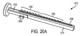
いくつかの実施形態による、プランジャーロッド1010の斜視図である。プランジャーロッド1010は、上述したように、プランジャーロッド1010の側方位置をシリンジバレル1009内に維持するためのスペーシングペグ1030を含む。プランジャーロッド1010は、つまみレスト1038に最も近いシャフトの一部に沿った長手方向の溝1070を含む。プランジャーロッドサブアセンブリが組み立てられるとき、弱い力及び強い力の歯車の一部がこの溝内に配置される。プランジャーロッド1010は、プランジャーロッド1010の長手方向の軸に垂直な断面が半円形であるような切欠部1072を含む。切欠部1072は、相補的な半円形断面を有する駆動ロッド1012の一部分に沿って摺動するための支持面を提供する。図20B、図20Cに図示されるいくつかの実施形態によれば、駆動ロッド1012は、より強い力の歯車1064の第2の組の歯1064Bと噛み合う1組の線形歯1024を含む。駆動ロッド1012の一部の断面輪郭は、プランジャーロッド1010の切欠部1072に嵌合して摺動するように構成される。それによって、プランジャーロッドと駆動ロッドとの間で確実に滑らかな相対的な軸方向運動ができ、かつ横方向の機構的な遊びが低減される。駆動ロッド1012は、駆動ロッド1012をシリンジバレル1009内に同心状に配置するための補助となる円筒状の端部部分を含んでいてもよい。
FIG. 3 is a perspective view of the
図21A、図21Bは、いくつかの実施形態による、プランジャーロッドサブアセンブリ1001の組立プロセスの態様を示す分解図である。図示の実施形態では、ハウジング1006は、本体1080A、バックカバー1080B、フロントカバー1080C、およびトップカバー1080Dの4つの構成要素を含む。フロントカバー1080Cのピン1082は、バックカバー1080Bの対応する穿孔1083に嵌合して、フロントカバーおよびバックカバーを本体に組み付ける。本体1080Aは、歯車ピン1084が挿入される複数の穴を含む。歯車のピン1084は、歯車列1011の歯車のためのシャフトを提供する。本体1080Aはまた、窓1044が摺動する溝を含む。トップカバー1080Dは、本体1080Aのユーザ側の端部の対応する穿孔に嵌合するピンを含む。上部カバー1080Dは、プランジャーロッド1010の回転を防止できるプランジャーロッド1010の断面輪郭と一致するように成形されたキャビティ1027を含む。それにより、プランジャーロッド1010は、並進移動できるが、回転することはできない。いくつかの実施形態では、プランジャーロッドサブアセンブリ1001とシリンジバレル1009との係合をプレロードするためにプレロードリング1086を設けてもよい。プレロードリング1086は、コイルばね、波形ばね、プラスチック、発泡体、またはゴムなどの弾性性材料のリングであってよく、または係合をプレロードするための任意の他の適切な構成要素であってもよい。
21A and 21B are exploded views showing aspects of the assembly process of the
以下は、いくつかの実施形態におけるプランジャーロッドサブアセンブリ1001の組み立てプロセスの説明である。以下のプロセスは例示のみを目的として示される。ステップは、異なる順序で実行されてもよく、特定の実施形態の様々な構成要素の構成に応じて、1つまたは複数のステップが省略されてもよく、および/または1つまたは複数の追加のステップが含まれてもよい。第1のステップでは、上部カバー1080Dは、例えば、アーバープレスを使用して本体1080A内に着座され、圧入される。次に、歯車の3つのピン1084が本体1080Aに圧入される。次に、つまみナット1013が本体1080Aの対応する部分に挿入され、裏蓋1080Bがハウジングの裏側に配置され、プレロードリング1086がハウジングのバレル開口部に挿入される。次に、より強い力の歯車1064が、対応する歯車のピン1084、つまりつまみナット1013から最も遠い歯車のピンに取り付けられる。次に、より弱い力の歯車1062が中央の歯車のピン1084上に取り付けられ、その第2の組の歯1062Bがより強い力の歯車1064の第1の組の歯1064Aと噛み合うように位置合わせされる。駆動ロッド1012は、ハウジング1006内のバレル開口部を通して挿入されて、ハウジングの位置合わせ機能部と位置合わせされ、それ自体の歯1024がより強い力の歯車1064上の第2の組の歯1064Bと噛み合うように押し込まれる。駆動ロッド1012は、ハウジング内の特定の深さまで挿入される。特定の深さは、特定の用途に応じて決定でき、工具を使用して制御可能である。
The following is a description of the assembly process of the
次のステップでは、プランジャーロッド1010が、最下部の投薬ラグ1029によりさらなる挿入が防止されるまで、トップカバー1080Dと、つまみナット1013とを通って挿入される。次に、回転歯車1060が残りの歯車ピン1084上に取り付けられ、より弱い力の歯車1062の第1の組の歯1062Aおよびプランジャーロッド1010の歯1028の両方に噛み合うように位置合わせされる。つまみナット1013を用量設定方向に回転させてプランジャーロッド1010上の投薬ラグ1029をつまみナット1013の雌ねじと係合させる。プランジャーロッド1010は、プランジャーロッド1010が所定の深さに達するまで、つまみナット1013を用量設定方向に連続的に回転させることにより、ハウジング1006内をさらに並進移動する。
In the next step, the
次に、窓1044は、本体1080A内の対応する溝に挿入されてもよい。次に、前面カバー1080Cは、本体1080Aの機能部および/または背面カバー1080Bの機能部と位置合わせされ、所定の位置に圧入される。これにより、いくつかの実施形態による、プランジャーロッドサブアセンブリ1001の組み立てが完了する。組み立てられたプランジャーロッドサブアセンブリ1001は、その後組み立てられてプレフィルドシリンジとなるか、または、正確で優れた精度の投薬プレフィルドシリンジシステムの最終組立品として貯蔵され、および/またはシリンジ充填業者に出荷するために包装される場合がある。
The
本発明の実施形態は、標準的な市販の構成要素の使用が可能な構成を提供できる。それによって全体的な製造コストを削減でき、組立工程を合理化でき、さらに非標準的な材料および構成要素にしばしば伴う規制問題を回避できる。例えば、シリンジバレルは、プラスチック、ガラス、または医療グレード製品に一般的に使用される別の材料でも作ることができる。1つまたは複数の構成要素は、ポリカーボネート(マサチューセッツ州のピッツフィールドに本社があるSABIC Innovative Plastics社から販売されている商品名「LEXAN(商標登録)」のものを含む)などのような任意の適切なプラスチックで作ることができる。任意の適切なエラストマーポリマーまたはゴム(例えばペンシルバニア州ペンサウケンのDatwyler Pharma Packaging USA Inc.から販売されている商品名「HELVOET(商標登録)」のゴム製品)をプランジャーシールのような部品に使用することができる。当業者によって理解されるように、ステンレス鋼のような様々な医療グレードの金属が、プランジャーロッド、駆動ロッド、歯車ピン、歯車、つまみナットなどのような1つ以上の構成要素に利用されてもよい。本明細書に記載された構成要素のいずれも、所望のパラメータに合った任意の構成で成形でき、または寸法決めすることもできる。本明細書に記載された構成要素のいずれも、単数の構成要素から成形でき、または複数のサブコンポーネントを含むことも可能である。構成要素は、接着剤を使用する工程、または超音波溶接などの溶接工程を含む任意の適切な工程によって構築および/または組み立てできる。 Embodiments of the invention can provide configurations that allow the use of standard commercially available components. It can reduce overall manufacturing costs, streamline assembly processes, and avoid regulatory issues often associated with non-standard materials and components. For example, the syringe barrel can be made of plastic, glass, or another material commonly used in medical grade products. One or more components may be any suitable, such as polycarbonate (including those with the trade name "LEXAN" sold by SABIC Innovative Plastics, headquartered in Pittsfield, Massachusetts). Can be made of polycarbonate. Use any suitable elastomeric polymer or rubber (eg, a rubber product under the trade name "HELVOET" sold by Datawyler Pharma Packing USA Inc. in Pennsylvania, Pennsylvania) for parts such as plunger seals. Can be done. As will be appreciated by those skilled in the art, various medical grade metals such as stainless steel are utilized in one or more components such as plunger rods, drive rods, gear pins, gears, knob nuts and the like. May be good. Any of the components described herein can be molded or sized in any configuration that meets the desired parameters. Any of the components described herein can be molded from a single component or can include multiple subcomponents. The components can be constructed and / or assembled by any suitable step, including a step using an adhesive or a welding step such as ultrasonic welding.
当業者であれば、本明細書に記載の原理および特徴に従う投薬機構、シリンジ、シリンジシステム等は、通常、眼内または眼上に注射可能な薬物送出、細胞内送出、放射性医薬品の送出、化学療法の送出等を含んだいかなる用途に対して構成できる。 For those of skill in the art, medication mechanisms, syringes, syringe systems, etc. according to the principles and features described herein are usually intraocular or intraocular injectable drug delivery, intracellular delivery, radiopharmaceutical delivery, chemistry. It can be configured for any use, including delivery of therapy.
以上の記載は、説明することが目的であって、特定の実施形態を参照して説明された。しかしながら、上記の例示した議論は網羅すること、または本発明を、開示された正確な形態に限定することを意図したものではない。上記の教示を考慮して多くの修正および変形が可能である。実施形態は、技術の原理およびそれらの実際の応用を最もよく説明するために選択、かつ記載された。それにより、当業者は、意図された特定の用途に適した様々な変更を行うことで、技術および様々な実施形態を最も有効に活用できる。 The above description is for the purpose of explanation and has been described with reference to specific embodiments. However, the above illustrated discussions are not intended to be exhaustive or to limit the invention to the exact form disclosed. Many modifications and modifications are possible in light of the above teachings. The embodiments have been selected and described to best explain the principles of the art and their practical application. Thereby, one of ordinary skill in the art can make the most effective use of the technique and various embodiments by making various changes suitable for the intended specific application.
開示物および実施例は、添付の図面を参照して十分に説明されているが、当業者には様々な変更および修正が明らかであることに留意されたい。そのような変更および改変は、本開示の範囲および特許請求の範囲によって規定される実施例に含まれ得ると理解されるべきである。最後に、本出願で示された特許および刊行物の全開示物は、参照により本明細書に組み込まれる。 Disclosures and examples are fully described with reference to the accompanying drawings, but it should be noted that various changes and amendments will be apparent to those of skill in the art. It should be understood that such changes and modifications may be included in the examples specified by the scope of the present disclosure and the claims. Finally, all disclosures of patents and publications presented in this application are incorporated herein by reference.
Claims (23)
第1の線形歯車を含む第1プランジャーロッド構成要素と、
第2の線形歯車を含む第2プランジャーロッド構成要素と、
ハウジングと、
前記ハウジングに対して並進運動しないように固定され、かつ、前記第1の線形歯車と噛み合う複数の歯を備える第1の回転歯車と、
前記ハウジングに対して並進運動しないように固定され、かつ、前記第2の線形歯車と噛み合う複数の第2の歯を備える第2の回転歯車と、
当該プランジャーロッドアセンブリをシリンジのバレルに固定する固定装置と、を備え、
前記第1の回転歯車および前記第2の回転歯車の少なくとも一方は、複合歯車の一部であり、
前記第1の回転歯車は、前記第1プランジャーロッド構成要素の前記ハウジングに対する並進運動によって前記第2プランジャーロッド構成要素が前記ハウジングに対して並進運動するように、前記第2の回転歯車に連結されていることを特徴とする、シリンジ用のプランジャーロッドアセンブリ。 Plunger rod assembly for syringes
A first plunger rod component, including a first linear gear,
A second plunger rod component, including a second linear gear,
With the housing
A first rotary gear that is fixed to the housing so as not to translate and has a plurality of teeth that mesh with the first linear gear.
A second rotary gear that is fixed to the housing so as not to translate and has a plurality of second teeth that mesh with the second linear gear.
A fixing device for fixing the plunger rod assembly to the barrel of the syringe is provided.
At least one of the first rotary gear and the second rotary gear is a part of a compound gear.
The first rotary gear is attached to the second rotary gear so that the second plunger rod component is translated with respect to the housing by the translational motion of the first plunger rod component with respect to the housing. Plunger rod assembly for syringes, characterized by being connected.
送出管と、
前記バレル内に配置されたプランジャーシールと、
前記バレルの端部に固定されたプランジャーロッドアセンブリと、を備え、
前記プランジャーロッドアセンブリは、
第1の線形歯車を備える第1プランジャーロッド構成要素と、
第2の線形歯車を備え、少なくとも部分的に前記バレル内に配置され、前記プランジャーシールと係合した第2プランジャーロッド構成要素と、
ハウジングと、
前記ハウジングに対して並進運動しないように固定され、かつ、前記第1の線形歯車と噛み合う複数の歯を備える第1の回転歯車と、
前記ハウジングに対して並進運動しないように固定され、かつ、前記第2の線形歯車と噛み合う第2の複数の歯を備える第2の回転歯車と、
前記プランジャーロッドアセンブリを上記バレルに固定する固定装置と、を備え、
前記第1の回転歯車および前記第2の回転歯車の少なくとも一方は、複合歯車の一部であり、
前記第1プランジャーロッド構成要素の前記ハウジングに対する並進運動により前記第2プランジャーロッド構成要素が前記ハウジングに対して並進運動するように、前記第1の回転歯車は、前記第2の回転歯車に連結されていることを特徴とする、シリンジ。 With a barrel,
Sending tube and
The plunger seal placed in the barrel and
With a plunger rod assembly fixed to the end of the barrel,
The plunger rod assembly is
A first plunger rod component with a first linear gear,
A second plunger rod component comprising a second linear gear, at least partially located within the barrel and engaged with the plunger seal.
With the housing
A first rotary gear that is fixed to the housing so as not to translate and has a plurality of teeth that mesh with the first linear gear.
A second rotary gear that is fixed to the housing so as not to translate and has a second plurality of teeth that mesh with the second linear gear.
A fixing device for fixing the plunger rod assembly to the barrel.
At least one of the first rotary gear and the second rotary gear is a part of a compound gear.
The first rotary gear is attached to the second rotary gear so that the translational motion of the first plunger rod component with respect to the housing causes the second plunger rod component to translate with respect to the housing. A syringe, characterized by being linked.
バレルと、
送出管と、
前記1回用量を前記送出管を通じて送出するように、前記バレル内に配置されたプランジャーシールと、
前記バレル内で前記プランジャーシールを前進させるために前記バレルの端部に固定されたプランジャーロッドアセンブリと、を備え、
前記プランジャーロッドアセンブリは、
前記バレルの端部に取り付けられたハウジングと、
少なくとも1つの突出部を備え、かつ、前記ハウジング内に少なくとも部分的に配置された、プランジャーロッド構成要素と、
前記プランジャーロッド構成要素の前記少なくとも1つの突出部に係合するように構成された、軸方向に固定された回転構成要素と、を備え、
ユーザによる前記回転構成要素の回転運動によって、前記回転構成要素と前記少なくとも1つの突出部との間の係合を介して、前記1回用量の送出の開始を設定するために、前記ハウジングに向かう前記プランジャーロッド構成要素の軸方向の並進運動が開始し、
前記回転構成要素から前記少なくとも1つの突出部が外れた後の、前記ハウジングに向かう、ユーザによる前記プランジャーロッド構成要素のその後の軸方向の並進運動によって、前記プランジャーシールがさらに前進して、前記1回用量が送出され、
前記プランジャーロッド構成要素と前記ハウジングとが接触することで前記1回用量の送出の完了が決定されることを特徴とする、シリンジ。 A syringe for delivering a single dose,
With a barrel,
Sending tube and
With a plunger seal placed in the barrel so that the single dose is delivered through the delivery tube.
A plunger rod assembly secured to the end of the barrel for advancing the plunger seal within the barrel.
The plunger rod assembly is
With the housing attached to the end of the barrel,
A plunger rod component having at least one protrusion and at least partially disposed within the housing.
An axially fixed rotational component configured to engage the at least one protrusion of the plunger rod component.
The rotational movement of the rotational component by the user towards the housing to set the initiation of delivery of the single dose via engagement between the rotational component and the at least one protrusion. Axial translational motion of the plunger rod component begins.
Subsequent axial translation of the plunger rod component towards the housing after the at least one protrusion has been dislodged from the rotating component further advances the plunger seal. The single dose was delivered and
A syringe comprising contact between the plunger rod component and the housing to determine the completion of delivery of the single dose.
前記駆動ロッド構成要素は、前記プランジャーロッド構成要素に対して軸方向に並進運動するように構成されており、かつ、前記プランジャーロッド構成要素の前記ハウジングに対する並進運動に応じて前記駆動ロッド構成要素が軸方向に前記ハウジングに対して並進運動するように、前記駆動ロッド構成要素が、少なくとも1つの回転歯車を介して前記プランジャーロッド構成要素と係合することを特徴とする、請求項12に記載のシリンジ。 The plunger rod assembly comprises a drive rod component that is at least partially located within the barrel and that engages the plunger seal.
The drive rod component is configured to translate axially with respect to the plunger rod component, and the drive rod component responds to the translational movement of the plunger rod component with respect to the housing. 12. The drive rod component engages the plunger rod component via at least one rotary gear so that the element translates axially with respect to the housing. The syringe described in.
Applications Claiming Priority (3)
| Application Number | Priority Date | Filing Date | Title |
|---|---|---|---|
| US201662323341P | 2016-04-15 | 2016-04-15 | |
| US62/323,341 | 2016-04-15 | ||
| PCT/US2017/026684 WO2017180480A1 (en) | 2016-04-15 | 2017-04-07 | Accurate, precise microliter dosing syringe |
Publications (3)
| Publication Number | Publication Date |
|---|---|
| JP2019511350A JP2019511350A (en) | 2019-04-25 |
| JP2019511350A5 JP2019511350A5 (en) | 2020-05-21 |
| JP7076106B2 true JP7076106B2 (en) | 2022-05-27 |
Family
ID=60041890
Family Applications (1)
| Application Number | Title | Priority Date | Filing Date |
|---|---|---|---|
| JP2019505122A Active JP7076106B2 (en) | 2016-04-15 | 2017-04-07 | Precise and accurate microliter dosing syringe |
Country Status (11)
| Country | Link |
|---|---|
| US (2) | US11707577B2 (en) |
| EP (2) | EP3442623B1 (en) |
| JP (1) | JP7076106B2 (en) |
| KR (1) | KR102385255B1 (en) |
| CN (1) | CN109069754B (en) |
| CA (1) | CA3018880A1 (en) |
| ES (1) | ES2860801T3 (en) |
| PT (1) | PT3442623T (en) |
| RU (1) | RU2738018C2 (en) |
| TW (1) | TWI755388B (en) |
| WO (1) | WO2017180480A1 (en) |
Families Citing this family (12)
| Publication number | Priority date | Publication date | Assignee | Title |
|---|---|---|---|---|
| CN117138171A (en) | 2017-12-13 | 2023-12-01 | 里珍纳龙药品有限公司 | Device and method for accurate dose delivery |
| WO2020065563A1 (en) * | 2018-09-26 | 2020-04-02 | Galderma S.A. | Injection device |
| US10722397B2 (en) | 2018-10-24 | 2020-07-28 | New World Medical, Inc. | Ophthalmic device |
| CN113226230B (en) * | 2018-10-24 | 2023-10-03 | 新世界医学有限公司 | Ophthalmic device |
| CA3119455A1 (en) * | 2018-11-13 | 2020-05-22 | Credence Medsystems, Inc. | System and method for multiple site injection |
| EP3886946A1 (en) | 2019-06-05 | 2021-10-06 | Regeneron Pharmaceuticals, Inc. | Devices and methods for precision dose delivery |
| GB2584730B (en) * | 2019-06-14 | 2022-04-13 | Owen Mumford Ltd | Drug delivery device assembly |
| WO2021097353A2 (en) * | 2019-11-14 | 2021-05-20 | Congruence Medical Solutions, Llc | Variable dosing syringe |
| WO2021257911A1 (en) | 2020-06-17 | 2021-12-23 | Credence Medsystems, Inc. | System and method for microdose injection |
| US20230285680A1 (en) * | 2022-03-11 | 2023-09-14 | Altek Biotechnology Corporation | Driving mechanism for driving a plunger of an auto-injector to slide relative to a reservoir of the auto-injector and auto-injector therewith |
| US20230343414A1 (en) | 2022-03-25 | 2023-10-26 | Illumina, Inc. | Sequence-to-sequence base calling |
| WO2023224584A1 (en) * | 2022-05-18 | 2023-11-23 | Bi̇med Tekni̇k Aletler Sanayi̇ Ve Ti̇caret Anoni̇m Şi̇rketi̇ | The adjustable-dosage syringe |
Citations (6)
| Publication number | Priority date | Publication date | Assignee | Title |
|---|---|---|---|---|
| JP2005520646A (en) | 2002-03-18 | 2005-07-14 | イーライ・リリー・アンド・カンパニー | Drug dispensing device with gear set giving mechanical advantages |
| WO2008101829A1 (en) | 2007-02-20 | 2008-08-28 | Novo Nordisk A/S | An injection device comprising a worm gear connection |
| US20120172815A1 (en) | 2009-04-01 | 2012-07-05 | Shl Group Ab | Medicament Delivery Device |
| US20130204193A1 (en) | 2010-04-19 | 2013-08-08 | Shl Group Ab | Self-Administration Medicament Delivery Device |
| US20140012227A1 (en) | 2012-07-03 | 2014-01-09 | Novartis Ag | Syringe |
| JP2015131114A (en) | 2013-05-07 | 2015-07-23 | イボクラール ビバデント アクチェンゲゼルシャフト | Rotary-spindle-syringe |
Family Cites Families (38)
| Publication number | Priority date | Publication date | Assignee | Title |
|---|---|---|---|---|
| US3122280A (en) | 1961-08-14 | 1964-02-25 | Clay Adams Inc | Adjustable stroke liquid dispenser having yieldable aligning means |
| US3770026A (en) | 1971-09-17 | 1973-11-06 | J Isenberg | Apparatus and method for accurately loading syringes |
| US4073321A (en) | 1976-03-15 | 1978-02-14 | George Moskowitz | Adjustable blocking means for dosage regulation |
| US4244366A (en) | 1979-10-30 | 1981-01-13 | Burron Medical, Inc. | Syringe stroke controlling mechanism |
| GB2109690B (en) | 1981-02-12 | 1985-02-20 | Robert Charles Turner | Dose metering plunger devices for use with syringes |
| US4563178A (en) | 1985-02-06 | 1986-01-07 | Santeramo Joseph J | Syringe dosage limiter |
| GB8809115D0 (en) | 1988-04-18 | 1988-05-18 | Turner R C | Syringes |
| US4921487A (en) | 1988-09-21 | 1990-05-01 | Compagnie Financiere Saint. Nicolas | External device for injecting medicine |
| US4929238A (en) | 1988-11-23 | 1990-05-29 | Coeur Laboratories, Inc. | Multi-pressure injector device |
| US5383858B1 (en) | 1992-08-17 | 1996-10-29 | Medrad Inc | Front-loading medical injector and syringe for use therewith |
| US5318544A (en) | 1992-10-20 | 1994-06-07 | Kerr Manufacturing Company | Metering syringe |
| DE29606540U1 (en) * | 1996-04-10 | 1997-08-07 | Muehlbauer Ernst | Dental mass application device |
| US5951526A (en) | 1997-09-24 | 1999-09-14 | Korisch; Marina | Syringe holder with integral dose divider |
| US7329241B2 (en) | 2003-02-14 | 2008-02-12 | Valeant Pharmaceuticals North America | Drug delivery system for administering an adjustable preset dose |
| US20050215957A1 (en) | 2004-03-26 | 2005-09-29 | Mallinckrodt Inc. | Calibrated pushrod for injection volume control in prefilled syringes |
| US20060217670A1 (en) * | 2005-03-28 | 2006-09-28 | Genx International, Inc. | Assembly for aspiration and/or dispensing of organisms and fluids |
| US20070073224A1 (en) | 2005-07-14 | 2007-03-29 | John Dries | Syringe with latching safety mechanism |
| EP1923083A1 (en) | 2006-11-17 | 2008-05-21 | Sanofi-Aventis Deutschland GmbH | Drive mechanisms for use in drug delivery devices |
| EP2237818B1 (en) | 2008-01-28 | 2016-11-16 | SHL Group AB | Injector with thumb operable scroll wheel |
| US8312785B2 (en) * | 2008-06-20 | 2012-11-20 | Graco Minnesota Inc. | Involute gear teeth for fluid metering device |
| EP2318075B1 (en) | 2008-08-05 | 2019-05-22 | Antares Pharma, Inc. | Multiple dosage injector |
| EP2331176B1 (en) | 2008-09-18 | 2020-10-28 | Becton, Dickinson and Company | Medical injector with rotatable body portions |
| EP2328639B1 (en) | 2008-09-18 | 2017-02-15 | Becton, Dickinson and Company | Medical injector with dose knob activation for automated reconstitution |
| SG171946A1 (en) | 2008-12-04 | 2011-07-28 | Sanofi Aventis Deutschland | Injection device with holding means to prevent unintentional movements of piston rod |
| ES2749395T3 (en) | 2009-11-20 | 2020-03-20 | Becton Dickinson Co | Injection device without the need for a gear |
| WO2011088894A1 (en) | 2010-01-20 | 2011-07-28 | Tecpharma Licensing Ag | Modular administration system for a liquid medicament |
| WO2012072554A1 (en) | 2010-11-29 | 2012-06-07 | Sanofi-Aventis Deutschland Gmbh | Drug delivery device |
| US8535277B2 (en) | 2011-03-21 | 2013-09-17 | William Marsh Rice University | Method and apparatus for dose measurement |
| CN103732275B (en) | 2011-06-17 | 2016-08-17 | Shl集团有限责任公司 | Injection device |
| MX351572B (en) * | 2011-12-08 | 2017-10-18 | Unitract Syringe Pty Ltd | Accurate dose control mechanisms and drug delivery syringes. |
| JP2016526993A (en) * | 2013-07-17 | 2016-09-08 | サノフイ | Drive mechanism |
| EP3054856B1 (en) | 2013-10-13 | 2020-12-09 | V.V.T. Med Ltd. | Device for synchronized injection and aspiration |
| GB2541227A (en) | 2015-08-13 | 2017-02-15 | Owen Mumford Ltd | Injector Device |
| US20180056009A1 (en) | 2016-09-01 | 2018-03-01 | Medimop Medical Projects Ltd. | Injector with variable dosage |
| WO2018085768A2 (en) | 2016-11-04 | 2018-05-11 | Shire | Small unit dosage plunger rod stops |
| US11389594B2 (en) | 2017-02-03 | 2022-07-19 | Norton Healthcare Limited | Assembly for a medication delivery device and medication delivery device |
| EP3576821A1 (en) | 2017-02-03 | 2019-12-11 | Norton Healthcare Limited | Assembly for a medication delivery device and medication delivery device |
| WO2021097353A2 (en) | 2019-11-14 | 2021-05-20 | Congruence Medical Solutions, Llc | Variable dosing syringe |
-
2017
- 2017-04-07 RU RU2018139650A patent/RU2738018C2/en active
- 2017-04-07 KR KR1020187031807A patent/KR102385255B1/en active IP Right Grant
- 2017-04-07 JP JP2019505122A patent/JP7076106B2/en active Active
- 2017-04-07 ES ES17782891T patent/ES2860801T3/en active Active
- 2017-04-07 PT PT177828910T patent/PT3442623T/en unknown
- 2017-04-07 EP EP17782891.0A patent/EP3442623B1/en active Active
- 2017-04-07 US US16/093,121 patent/US11707577B2/en active Active
- 2017-04-07 CN CN201780023860.9A patent/CN109069754B/en active Active
- 2017-04-07 WO PCT/US2017/026684 patent/WO2017180480A1/en active Application Filing
- 2017-04-07 EP EP21152295.8A patent/EP3834868A1/en active Pending
- 2017-04-07 CA CA3018880A patent/CA3018880A1/en active Pending
- 2017-04-14 TW TW106112496A patent/TWI755388B/en active
-
2023
- 2023-07-17 US US18/353,287 patent/US20230355885A1/en active Pending
Patent Citations (6)
| Publication number | Priority date | Publication date | Assignee | Title |
|---|---|---|---|---|
| JP2005520646A (en) | 2002-03-18 | 2005-07-14 | イーライ・リリー・アンド・カンパニー | Drug dispensing device with gear set giving mechanical advantages |
| WO2008101829A1 (en) | 2007-02-20 | 2008-08-28 | Novo Nordisk A/S | An injection device comprising a worm gear connection |
| US20120172815A1 (en) | 2009-04-01 | 2012-07-05 | Shl Group Ab | Medicament Delivery Device |
| US20130204193A1 (en) | 2010-04-19 | 2013-08-08 | Shl Group Ab | Self-Administration Medicament Delivery Device |
| US20140012227A1 (en) | 2012-07-03 | 2014-01-09 | Novartis Ag | Syringe |
| JP2015131114A (en) | 2013-05-07 | 2015-07-23 | イボクラール ビバデント アクチェンゲゼルシャフト | Rotary-spindle-syringe |
Also Published As
| Publication number | Publication date |
|---|---|
| CN109069754A (en) | 2018-12-21 |
| CN109069754B (en) | 2021-09-07 |
| ES2860801T3 (en) | 2021-10-05 |
| RU2018139650A (en) | 2020-05-15 |
| EP3442623B1 (en) | 2021-01-20 |
| EP3442623A4 (en) | 2019-10-23 |
| EP3442623A1 (en) | 2019-02-20 |
| RU2738018C2 (en) | 2020-12-07 |
| US20210178080A1 (en) | 2021-06-17 |
| WO2017180480A1 (en) | 2017-10-19 |
| US20230355885A1 (en) | 2023-11-09 |
| KR102385255B1 (en) | 2022-04-08 |
| US11707577B2 (en) | 2023-07-25 |
| JP2019511350A (en) | 2019-04-25 |
| WO2017180480A8 (en) | 2018-09-13 |
| TWI755388B (en) | 2022-02-21 |
| TW201801761A (en) | 2018-01-16 |
| EP3834868A1 (en) | 2021-06-16 |
| RU2018139650A3 (en) | 2020-07-24 |
| CA3018880A1 (en) | 2017-10-19 |
| PT3442623T (en) | 2021-02-17 |
| KR20180134937A (en) | 2018-12-19 |
Similar Documents
| Publication | Publication Date | Title |
|---|---|---|
| JP7076106B2 (en) | Precise and accurate microliter dosing syringe | |
| JP5080976B2 (en) | Method for assembling drug delivery device | |
| US7090662B2 (en) | Dose dial and drive mechanisms suitable for use in drug delivery devices | |
| JP6298946B2 (en) | Accurate dosing control mechanism and syringe for drug delivery | |
| JP2023106526A (en) | Devices and methods for accurate dose delivery | |
| US10328211B2 (en) | Automatic self-dispensing accurate dose drug delivery syringes | |
| AU2014328035B2 (en) | Automatic self-dispensing accurate dose drug delivery syringes | |
| AU2004222587B2 (en) | Dose dial and drive mechanism suitable for use in drug delivery devices | |
| EA041108B1 (en) | DEVICE AND METHOD FOR PRECISION DOSE DELIVERY |
Legal Events
| Date | Code | Title | Description |
|---|---|---|---|
| A521 | Request for written amendment filed |
Free format text: JAPANESE INTERMEDIATE CODE: A523 Effective date: 20200407 |
|
| A621 | Written request for application examination |
Free format text: JAPANESE INTERMEDIATE CODE: A621 Effective date: 20200407 |
|
| A131 | Notification of reasons for refusal |
Free format text: JAPANESE INTERMEDIATE CODE: A131 Effective date: 20210202 |
|
| A601 | Written request for extension of time |
Free format text: JAPANESE INTERMEDIATE CODE: A601 Effective date: 20210428 |
|
| A521 | Request for written amendment filed |
Free format text: JAPANESE INTERMEDIATE CODE: A523 Effective date: 20210701 |
|
| A131 | Notification of reasons for refusal |
Free format text: JAPANESE INTERMEDIATE CODE: A131 Effective date: 20210914 |
|
| A521 | Request for written amendment filed |
Free format text: JAPANESE INTERMEDIATE CODE: A523 Effective date: 20211214 |
|
| TRDD | Decision of grant or rejection written | ||
| A01 | Written decision to grant a patent or to grant a registration (utility model) |
Free format text: JAPANESE INTERMEDIATE CODE: A01 Effective date: 20220405 |
|
| A61 | First payment of annual fees (during grant procedure) |
Free format text: JAPANESE INTERMEDIATE CODE: A61 Effective date: 20220428 |
|
| R150 | Certificate of patent or registration of utility model |
Ref document number: 7076106 Country of ref document: JP Free format text: JAPANESE INTERMEDIATE CODE: R150 |