JP5378564B2 - Electronics - Google Patents

Electronics Download PDF

Info

Publication number
JP5378564B2
JP5378564B2 JP2012102637A JP2012102637A JP5378564B2 JP 5378564 B2 JP5378564 B2 JP 5378564B2 JP 2012102637 A JP2012102637 A JP 2012102637A JP 2012102637 A JP2012102637 A JP 2012102637A JP 5378564 B2 JP5378564 B2 JP 5378564B2
Authority
JP
Japan
Prior art keywords
wall
housing
wall portion
fan
portions
Prior art date
Legal status (The legal status is an assumption and is not a legal conclusion. Google has not performed a legal analysis and makes no representation as to the accuracy of the status listed.)
Active
Application number
JP2012102637A
Other languages
Japanese (ja)
Other versions
JP2013232720A (en
Inventor
伸人 藤原
Current Assignee (The listed assignees may be inaccurate. Google has not performed a legal analysis and makes no representation or warranty as to the accuracy of the list.)
Toshiba Corp
Original Assignee
Toshiba Corp
Priority date (The priority date is an assumption and is not a legal conclusion. Google has not performed a legal analysis and makes no representation as to the accuracy of the date listed.)
Filing date
Publication date
Application filed by Toshiba Corp filed Critical Toshiba Corp
Priority to JP2012102637A priority Critical patent/JP5378564B2/en
Priority to US13/727,881 priority patent/US20130286297A1/en
Publication of JP2013232720A publication Critical patent/JP2013232720A/en
Application granted granted Critical
Publication of JP5378564B2 publication Critical patent/JP5378564B2/en
Active legal-status Critical Current
Anticipated expiration legal-status Critical

Links

Images

Classifications

    • HELECTRICITY
    • H04ELECTRIC COMMUNICATION TECHNIQUE
    • H04NPICTORIAL COMMUNICATION, e.g. TELEVISION
    • H04N5/00Details of television systems
    • H04N5/64Constructional details of receivers, e.g. cabinets or dust covers
    • GPHYSICS
    • G06COMPUTING OR CALCULATING; COUNTING
    • G06FELECTRIC DIGITAL DATA PROCESSING
    • G06F1/00Details not covered by groups G06F3/00 - G06F13/00 and G06F21/00
    • G06F1/16Constructional details or arrangements
    • G06F1/20Cooling means
    • G06F1/203Cooling means for portable computers, e.g. for laptops
    • HELECTRICITY
    • H05ELECTRIC TECHNIQUES NOT OTHERWISE PROVIDED FOR
    • H05KPRINTED CIRCUITS; CASINGS OR CONSTRUCTIONAL DETAILS OF ELECTRIC APPARATUS; MANUFACTURE OF ASSEMBLAGES OF ELECTRICAL COMPONENTS
    • H05K7/00Constructional details common to different types of electric apparatus
    • H05K7/20Modifications to facilitate cooling, ventilating, or heating
    • H05K7/20009Modifications to facilitate cooling, ventilating, or heating using a gaseous coolant in electronic enclosures
    • H05K7/20136Forced ventilation, e.g. by fans
    • H05K7/20145Means for directing air flow, e.g. ducts, deflectors, plenum or guides
    • HELECTRICITY
    • H05ELECTRIC TECHNIQUES NOT OTHERWISE PROVIDED FOR
    • H05KPRINTED CIRCUITS; CASINGS OR CONSTRUCTIONAL DETAILS OF ELECTRIC APPARATUS; MANUFACTURE OF ASSEMBLAGES OF ELECTRICAL COMPONENTS
    • H05K7/00Constructional details common to different types of electric apparatus
    • H05K7/20Modifications to facilitate cooling, ventilating, or heating
    • H05K7/20954Modifications to facilitate cooling, ventilating, or heating for display panels

Landscapes

  • Engineering & Computer Science (AREA)
  • Physics & Mathematics (AREA)
  • Microelectronics & Electronic Packaging (AREA)
  • Theoretical Computer Science (AREA)
  • Thermal Sciences (AREA)
  • Multimedia (AREA)
  • Signal Processing (AREA)
  • Computer Hardware Design (AREA)
  • Human Computer Interaction (AREA)
  • General Engineering & Computer Science (AREA)
  • General Physics & Mathematics (AREA)
  • Cooling Or The Like Of Electrical Apparatus (AREA)

Description

本発明の実施形態は、電子機器に関する。 Embodiments of the present invention relates to electronic devices.

従来、筐体にファンが設けられた電子機器が、知られている。   2. Description of the Related Art Conventionally, an electronic device having a housing provided with a fan is known.

特開2007−149007号公報JP 2007-149007 A

ファンが設けられた電子機器では、ファンに関連した新規な構成によって、例えばより構成が簡素化される等の利点が得られたり、不都合が少なくなったりするのは、好ましい。   In an electronic device provided with a fan, it is preferable that an advantage such as a simpler structure can be obtained or inconvenience can be reduced by a new structure related to the fan.

そこで、本発明の実施形態は、一例として、ファンに関連した新規な構成によって不都合が減るあるいは利点が得られる電子機器を得ることを、目的の一つとする。 Accordingly, embodiments of the present invention, as an example, to obtain a new child devices electrodeposition that obtained decreases or advantages disadvantages by structure associated with the fan, and one of the objects.

実施形態によれば、電子機器は、筐体と、前記筐体内で回転可能に設けられたファンと
、 前記ファンと重なった通気口が設けられ前記ファンが収容された空間を構成するとと
もに前記ファンに面した前記筐体の第一の壁部と、前記第一の壁部とは別体であり、前記
第一の壁部より前記筐体内側で前記ファンの前記第一の壁部とは反対側に位置され、当該
第一の壁部に取り付けられ、前記ファンが収容された空間を構成するとともに前記ファン
に面した第二の壁部と、前記第一の壁部と前記第二の壁部との間に亘った第三の壁部と、
を備え、前記第三の壁部は、前記第二の壁部から一体的に突出し、前記第三の壁部の前記
第一の壁部側の端部と前記第一の壁部との間の隙間を覆う覆部が設けられた。
According to the embodiment, the electronic device includes a housing and a fan that is rotatably provided in the housing.
A vent hole that overlaps with the fan is provided to form a space in which the fan is accommodated.
The first wall portion of the housing facing the fan is separate from the first wall portion, and
It is located on the opposite side to the first wall portion of the fan inside the housing from the first wall portion,
The fan is attached to the first wall and forms a space in which the fan is accommodated, and the fan
A second wall facing the first wall and a third wall extending between the first wall and the second wall;
The third wall portion integrally protrudes from the second wall portion, and the third wall portion
The cover part which covers the clearance gap between the edge part on the 1st wall part side and said 1st wall part was provided.

図1は、第1実施形態にかかるテレビジョン受像機の一例の正面図である。FIG. 1 is a front view of an example of a television receiver according to the first embodiment. 図2は、第1実施形態にかかるテレビジョン受像機の一例の側面図である。FIG. 2 is a side view of an example of the television receiver according to the first embodiment. 図3は、図1のIII−III線での模式的な断面図である。3 is a schematic cross-sectional view taken along line III-III in FIG. 図4は、第1実施形態にかかるテレビジョン受像機に含まれたファンの一例の平面図である。FIG. 4 is a plan view of an example of a fan included in the television receiver according to the first embodiment. 図5は、第1実施形態にかかるテレビジョン受像機に含まれたファンユニットの一例の正面図である。FIG. 5 is a front view of an example of a fan unit included in the television receiver according to the first embodiment. 図6は、第2実施形態にかかるテレビジョン受像機の図3と同等位置での断面図である。FIG. 6 is a cross-sectional view of the television receiver according to the second embodiment at the same position as in FIG. 図7は、第3実施形態にかかる電子機器の一例の斜視図である。FIG. 7 is a perspective view of an example of an electronic apparatus according to the third embodiment. 図8は、第3実施形態にかかる電子機器の第二筐体の一例の平面図(下面図)である。FIG. 8 is a plan view (bottom view) of an example of the second housing of the electronic device according to the third embodiment. 図9は、図8のIX−IX断面図である。9 is a cross-sectional view taken along the line IX-IX in FIG. 図10は、第3実施形態の第1変形例にかかる電子機器の一例の、図9と同等位置での断面図である。FIG. 10 is a cross-sectional view of an example of an electronic apparatus according to a first modification of the third embodiment at the same position as FIG. 図11は、第3実施形態の第2変形例にかかる電子機器の第三壁部の一例が示された断面図である。FIG. 11 is a cross-sectional view illustrating an example of a third wall portion of an electronic device according to a second modification of the third embodiment. 図12は、第3実施形態の第3変形例にかかる電子機器の第三壁部の一例が示された断面図である。FIG. 12 is a cross-sectional view illustrating an example of a third wall portion of an electronic device according to a third modification of the third embodiment. 図13は、第3実施形態の第4変形例にかかる電子機器のファンの軸受部の一例が示された断面図である。FIG. 13 is a cross-sectional view illustrating an example of a bearing portion of a fan of an electronic device according to a fourth modification of the third embodiment. 図14は、第3実施形態の第5変形例にかかる電子機器のファンの軸受部の一例が示された断面図である。FIG. 14 is a cross-sectional view illustrating an example of a bearing portion of a fan of an electronic device according to a fifth modification of the third embodiment.

以下の例示的な複数の実施形態には、同様の構成要素が含まれている。よって、以下では、同様の構成要素には共通の符号が付されるとともに、重複する説明が省略される。   The following exemplary embodiments include similar components. Therefore, below, the same code | symbol is attached | subjected to the same component, and the overlapping description is abbreviate | omitted.

また、以下の実施形態では、電子機器がテレビジョン受像機や所謂ノートブック型(クラムシェル型)のパーソナルコンピュータとして構成された場合が例示されるが、本実施形態にかかる電子機器は、これには限定されない。本実施形態にかかる電子機器は、ファンを備えた電子機器、具体的には、例えば、所謂デスクトップ型やタブレット型(スレート型)のパーソナルコンピュータや、スマートテレビ、映像表示装置、プロジェクタ等として構成することができる。   Further, in the following embodiment, the case where the electronic device is configured as a television receiver or a so-called notebook type (clamshell type) personal computer is exemplified, but the electronic device according to the present embodiment is not limited thereto. Is not limited. The electronic device according to the present embodiment is configured as an electronic device provided with a fan, specifically, for example, a so-called desktop type or tablet type (slate type) personal computer, smart TV, video display device, projector, or the like. be able to.

<第1実施形態>
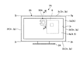
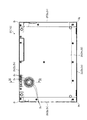
本実施形態では、一例として、図1,2に示されるように、テレビジョン受像機1A(電子機器)は、支持部2Aと筐体3Aとを備える。具体的に、筐体3Aには、表示装置4の少なくとも一部が収容されている。支持部2A(スタンド部、台部、脚部)は、筐体3Aを支持する。支持部2Aは、筐体3Aを、移動可能(回動可能)に支持することができる。その場合の筐体3Aの動きとしては、例えば、チルト、ピボット、スイベル等がある。
<First Embodiment>
In the present embodiment, as an example, as illustrated in FIGS. 1 and 2, the television receiver 1 </ b> A (electronic device) includes a support portion 2 </ b> A and a housing 3 </ b> A. Specifically, at least a part of the display device 4 is accommodated in the housing 3A. The support part 2A (stand part, base part, leg part) supports the housing 3A. The support portion 2A can support the housing 3A so as to be movable (rotatable). Examples of the movement of the housing 3A in that case include tilt, pivot, swivel, and the like.

筐体3Aは、本実施形態では、一例として、図1に示されるように、正面視および背面視では四角形状(本実施形態では、一例として長方形状)に構成されている。また、筐体3Aは、本実施形態では、一例として、図2に示されるように、前後方向に薄い扁平な直方体状に構成されている。筐体3Aは、面3a(前面、上面、正面、面部)とこの反対側の面3b(後面、下面、背面、面部)と、を有する。面3aと面3bとは略平行している。また、筐体3Aは、図1に示されるように、正面視では、四つの端部3c〜3f(辺部、縁部)と、四つの角部3g〜3j(尖部、曲部、端部)と、を有する。端部3c,3eは、長辺部の一例である。また、端部3d,3fは、短辺部の一例である。   In the present embodiment, as an example, the housing 3 </ b> A is configured in a quadrangular shape (in the present embodiment, a rectangular shape as an example) in the front view and the rear view, as shown in FIG. 1. In the present embodiment, as an example, the housing 3 </ b> A is configured in a flat rectangular parallelepiped shape that is thin in the front-rear direction, as shown in FIG. 2. The housing 3A has a surface 3a (front surface, upper surface, front surface, surface portion) and an opposite surface 3b (rear surface, lower surface, back surface, surface portion). The surface 3a and the surface 3b are substantially parallel. As shown in FIG. 1, the housing 3 </ b> A has four end portions 3 c to 3 f (side portions and edge portions) and four corner portions 3 g to 3 j (pointed portions, curved portions, end portions) in a front view. Part). The end portions 3c and 3e are examples of long side portions. The ends 3d and 3f are examples of short sides.

また、筐体3Aは、一例として、面3aを有する壁部3k(部分、プレート、フレーム、前壁部、表壁部、天壁部)と、面3bを有する壁部3m(部分、プレート、後壁部、裏壁部、底壁部)と、を有する。壁部3k,3mは、四角形状(本実施形態では、一例として長方形状)である。また、筐体3Aは、壁部3kと壁部3mとの間に亘った面3p(側面、周面)を有する四つの壁部3n(部分、プレート、側壁部、端壁部、立壁部、亘部)を有する。なお、壁部3kには、一例としては四角形状の開口部3rが設けられている。よって、壁部3kは、四角形状かつ枠状である。   As an example, the housing 3A includes a wall 3k (part, plate, frame, front wall, front wall, top wall, top wall) having a surface 3a and a wall 3m (part, plate, Rear wall portion, back wall portion, bottom wall portion). The walls 3k and 3m have a quadrangular shape (in this embodiment, a rectangular shape as an example). Further, the housing 3A has four wall portions 3n (parts, plates, side wall portions, end wall portions, standing wall portions, having a surface 3p (side surface, peripheral surface) extending between the wall portions 3k and 3m. Have a cross section). The wall 3k is provided with, for example, a quadrangular opening 3r. Therefore, the wall 3k has a rectangular shape and a frame shape.

さらに、筐体3Aは、複数の部品(分割体)が組み合わせられて構成されることができる。筐体3Aは、本実施形態では、一例として、少なくとも壁部3kを含む第一筐体部材31(第一部分、前側部材、マスク、マスク部、カバー、フロントカバー、カバー部、第一領域)と、少なくとも壁部3mを含む第二筐体部材32(第二部分、後側部材、ベース、ベース部、ボトム、ボトム部、カバー、リヤカバー、カバー部、第二領域)とを有する。壁部3nは、第一筐体部材31および第二筐体部材32のうち少なくともいずれか一方(例えば、第二筐体部材32)に含まれる。また、筐体3Aは、第一筐体部材31および第二筐体部材32とは別に、これらの間に位置した第三筐体部材(第三部分、中間部材、隔部材、障壁部材、壁部材、介在部材、インナプレート、ミドルプレート、ミドルフレーム、第三領域、図示されず)や、第四筐体部材(第四部分、中間部材、隔部材、障壁部材、壁部材、介在部材、覆部材、シールド、第四領域、図示されず)等を有することができる。筐体3Aは、金属材料や、合成樹脂材料等で構成されることができる。なお、第一筐体部材31や第二筐体部材32の筐体3A内側には、リブ等の壁部(突出部、突出壁部、図示されず)が設けられることができる。これら壁部により、筐体3Aの剛性が高くなりやすい。   Further, the housing 3A can be configured by combining a plurality of components (divided bodies). In this embodiment, the housing 3A includes, as an example, a first housing member 31 (a first portion, a front member, a mask, a mask portion, a cover, a front cover, a cover portion, and a first region) including at least a wall portion 3k. And a second casing member 32 (second portion, rear member, base, base portion, bottom, bottom portion, cover, rear cover, cover portion, second region) including at least the wall portion 3m. The wall 3n is included in at least one of the first housing member 31 and the second housing member 32 (for example, the second housing member 32). The housing 3A is separated from the first housing member 31 and the second housing member 32 by a third housing member (a third portion, an intermediate member, a separating member, a barrier member, a wall, and the like). Member, interposition member, inner plate, middle plate, middle frame, third region, not shown) and fourth housing member (fourth part, intermediate member, separation member, barrier member, wall member, interposition member, cover) Member, shield, fourth region, not shown) and the like. The housing 3A can be made of a metal material, a synthetic resin material, or the like. Note that wall portions (protruding portions, protruding wall portions, not shown) such as ribs can be provided inside the housing 3A of the first housing member 31 and the second housing member 32. These walls tend to increase the rigidity of the housing 3A.

また、本実施形態では、一例として、筐体3Aの面3bや面3p等には、コネクタや操作部等(図示されず)が設けられることができる。コネクタは、例えば、電源ケーブル用のコネクタや、USB(universal serial bus)コネクタ、カードコネクタ、イヤホンやマイクのコネクタ等であることができる。操作部は、例えば、押しボタンや、押しスイッチ、スライドスイッチ、ポインティングデバイス、ダイヤル等であることができる。また、面3aには、カメラモジュール(カメラ、撮像装置、図示されず)を設けることができる。   In the present embodiment, as an example, a connector, an operation unit, and the like (not shown) can be provided on the surface 3b, the surface 3p, and the like of the housing 3A. The connector can be, for example, a connector for a power cable, a USB (universal serial bus) connector, a card connector, an earphone or microphone connector, or the like. The operation unit can be, for example, a push button, a push switch, a slide switch, a pointing device, a dial, or the like. Further, a camera module (camera, imaging device, not shown) can be provided on the surface 3a.

また、本実施形態では、一例として、図1に示されるように、表示装置4(表示部、ディスプレイ、パネル)の、面3a側に位置した表示画面4aは、開口部3rを介して筐体3Aの前方(外方)に露出している。ユーザ等は、前方側から開口部3rを介して表示画面4aを視認することができる。表示装置4は、正面視では四角形状(本実施形態では一例として長方形状)に構成されている。また、表示装置4は、前後方向に薄い扁平な直方体状に構成されている。表示装置4は、例えば、液晶ディスプレイ(LCD,liquid crystal display)や有機ELディスプレイ(OELD,organic electro-luminescent display)等である。   In the present embodiment, as an example, as shown in FIG. 1, the display screen 4 a positioned on the surface 3 a side of the display device 4 (display unit, display, panel) is a housing through the opening 3 r. It is exposed to the front (outside) of 3A. A user or the like can visually recognize the display screen 4a from the front side through the opening 3r. The display device 4 is configured in a quadrangular shape (in the present embodiment, a rectangular shape as an example) when viewed from the front. The display device 4 is configured in a flat rectangular parallelepiped shape that is thin in the front-rear direction. The display device 4 is, for example, a liquid crystal display (LCD), an organic EL display (OELD, organic electro-luminescent display), or the like.

また、本実施形態では、一例として、表示装置4の前側(表側、壁部3k側)には、タッチパネル5(一例としては入力操作パネル、タッチセンサ、操作面、カバー)が設けられている。タッチパネル5は、透明な比較的薄い四角形状に構成され、表示画面4aを覆っている。ユーザ等は、例えば、手指や部品(例えばスタイラス等、図示されず)等でタッチパネル5に対して、触れる、押す、擦る、あるいは手指やスタイラス等をタッチパネル5の近傍で動かす等の操作を行うことで、入力処理を実行することができる。また、表示装置4の表示画面4aから出た光は、タッチパネル5を通過して壁部3kの開口部3rから筐体3Aの前方(外方)へ出る。   Moreover, in this embodiment, the touch panel 5 (an input operation panel, a touch sensor, an operation surface, a cover as an example) is provided in the front side (front side, wall part 3k side) of the display apparatus 4 as an example. The touch panel 5 is configured in a transparent relatively thin square shape and covers the display screen 4a. The user or the like, for example, performs an operation such as touching, pushing, rubbing, or moving a finger or stylus in the vicinity of the touch panel 5 with a finger or a part (for example, a stylus, not shown). Thus, the input process can be executed. Further, the light emitted from the display screen 4a of the display device 4 passes through the touch panel 5 and exits from the opening 3r of the wall 3k to the front (outward) of the housing 3A.

そして、本実施形態では、一例として、筐体3A内には、表示装置4の後側(裏側、背後側、壁部3m側、表示画面4aとは反対側)に、一つ以上の基板6(回路基板、制御基板、メイン基板、電気部品、部品)が収容されている。基板6は、表示装置4と並行して設けられている。基板6は、壁部3k,3m,3n等と離間した状態で、すなわち、壁部3k,3m,3n等との間に空間(隙間)が形成された状態で、設けられている。   In the present embodiment, as an example, in the housing 3A, one or more substrates 6 are provided on the rear side of the display device 4 (the back side, the back side, the wall 3m side, the side opposite to the display screen 4a). (Circuit board, control board, main board, electrical component, component) are accommodated. The substrate 6 is provided in parallel with the display device 4. The substrate 6 is provided in a state of being separated from the wall portions 3k, 3m, 3n and the like, that is, in a state where a space (gap) is formed between the wall portions 3k, 3m, 3n and the like.

また、本実施形態では、一例として、基板6には、例えば、CPU(central processing unit)や、グラフィックコントローラ、電源回路部品、PCH(platform controller hub)、メモリスロットコネクタ、LCDコネクタ、I/O(input/output)コネクタ、電源コイル、素子、コネクタ等の複数の部品(図示されず)を実装することができる。また、制御回路は、例えば、映像信号処理回路や、チューナ部、HDMI(high-definition multimedia interface)信号処理部、AV(audio video)入力端子、リモコン信号受信部、制御部、セレクタ、オンスクリーンディスプレイインタフェース、記憶部(例えば、ROM(read only memory)、RAM(random access memory)、HDD(hard disk drive)、SSD(solid state drive)等)、音声信号処理回路等を、含むことができる。制御回路は、表示装置4の表示画面4aでの映像(動画や静止画等)の出力や、スピーカ(図示されず)での音声の出力、LED(light emitting diode、図示されず)での発光等を制御する。表示装置4や、スピーカ、LED等は、出力部の一例である。   In this embodiment, as an example, the substrate 6 includes, for example, a central processing unit (CPU), a graphic controller, a power supply circuit component, a PCH (platform controller hub), a memory slot connector, an LCD connector, an I / O (I / O). A plurality of components (not shown) such as input / output) connectors, power supply coils, elements, and connectors can be mounted. The control circuit includes, for example, a video signal processing circuit, a tuner unit, an HDMI (high-definition multimedia interface) signal processing unit, an AV (audio video) input terminal, a remote control signal receiving unit, a control unit, a selector, an on-screen display An interface, a storage unit (for example, ROM (read only memory), RAM (random access memory), HDD (hard disk drive), SSD (solid state drive), etc.), an audio signal processing circuit, and the like can be included. The control circuit outputs video (moving images, still images, etc.) on the display screen 4a of the display device 4, outputs audio from a speaker (not shown), and emits light from an LED (light emitting diode, not shown). Control etc. The display device 4, the speaker, the LED, and the like are examples of the output unit.

また、本実施形態では、一例として、図1,3に示されるように、ファンユニット50Aが設けられている。ファンユニット50A(空冷装置、冷却装置)は、ファン61を回転させることにより、空気を吸入し排出する。ファン61の回転によって形成された空気流により、筐体3Aの内部の発熱体(部品、電子部品、電気部品、発熱部)や、冷却装置の熱交換器(熱交換部、放熱フィン)等が冷却される。   In the present embodiment, as an example, a fan unit 50A is provided as shown in FIGS. The fan unit 50A (air cooling device, cooling device) sucks and discharges air by rotating the fan 61. Due to the air flow formed by the rotation of the fan 61, the heating elements (components, electronic components, electrical components, heat generating portions) inside the housing 3A, the heat exchangers (heat exchanging portions, radiating fins) of the cooling device, etc. To be cooled.

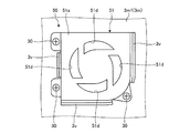
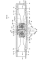
また、本実施形態では、一例として、図3に示されるように、ファンユニット50Aは、筐体3Aの壁部3m(外壁部、天壁部、底壁部、第一の壁部)の面3bとは反対側の面3m1(内面、筐体内側の面)に取り付けられている。本実施形態では、一例として、ファンユニット50Aは、軸方向一方側に開放されており、当該軸方向一方側の壁部を有さない。換言すれば、壁部3mが、ファンユニット50Aのケース(筐体)の一部(回転軸Axの軸方向一方側の壁部)として構成されている。壁部3mは、ファン61の軸方向一方側を覆っている。壁部3mには、通気口3sが設けられている。   In the present embodiment, as an example, as shown in FIG. 3, the fan unit 50 </ b> A has a surface of the wall portion 3 m (outer wall portion, top wall portion, bottom wall portion, first wall portion) of the housing 3 </ b> A. It is attached to a surface 3m1 (inner surface, inner surface of the housing) opposite to 3b. In the present embodiment, as an example, the fan unit 50A is opened on one side in the axial direction and does not have a wall portion on the one side in the axial direction. In other words, the wall 3m is configured as a part of the case (housing) of the fan unit 50A (a wall on one side in the axial direction of the rotation axis Ax). The wall 3 m covers one side of the fan 61 in the axial direction. The wall 3m is provided with a vent 3s.

すなわち、本実施形態では、一例として、壁部51a(内壁部、天壁部、底壁部、第二の壁部、ケース)と壁部51c(側壁部、周壁部、亘部、第三の壁部、ケース)とが一体化され、ケース部品51が構成されている。本実施形態では、一例として、ケース部品51は、図5に示されるように、結合具30(固定具、例えばねじ等)によって、壁部3mの面3m1上に取り付けられている。   That is, in this embodiment, as an example, the wall part 51a (inner wall part, top wall part, bottom wall part, second wall part, case) and wall part 51c (side wall part, peripheral wall part, span part, third part) A wall part, a case) and the case part 51 are configured. In the present embodiment, as an example, the case component 51 is attached on the surface 3m1 of the wall 3m by a coupler 30 (fixing tool, for example, a screw) as shown in FIG.

壁部51aは、ファン61の壁部3mとは反対側(回転軸Axの軸方向他方側、筐体内側)に設けられ、回転軸Axと交叉する方向(直交する方向)に拡がっている。すなわち、壁部51aは、ファン61の筐体内側(軸方向他方側)を覆っている。壁部51aは、壁部3mと略平行である。壁部51aには、通気口51dが設けられている。また、壁部51cは、壁部3mと壁部51aとの間に亘っている。壁部51cには、通気口51fが設けられている。通気口51fは、ファン61の径方向の一方側(本実施形態では、一例として図1の上側)に設けられている。すなわち、壁部51cは、通気口51fが設けられた部分以外で、ファン61の径方向外側を、覆っている。   The wall 51a is provided on the side opposite to the wall 3m of the fan 61 (the other side in the axial direction of the rotation axis Ax, the inside of the housing), and extends in a direction crossing the rotation axis Ax (orthogonal direction). That is, the wall 51 a covers the inside of the housing of the fan 61 (the other side in the axial direction). The wall 51a is substantially parallel to the wall 3m. The wall 51a is provided with a vent 51d. The wall 51c extends between the wall 3m and the wall 51a. The wall 51c is provided with a vent 51f. The vent 51f is provided on one side of the fan 61 in the radial direction (in the present embodiment, as an example, the upper side in FIG. 1). That is, the wall 51c covers the outside in the radial direction of the fan 61 except for the portion where the vent 51f is provided.

通気口3s,51dは、ファンユニット50Aの厚さ方向(回転軸Axの軸方向、筐体3Aの厚さ方向、壁部3mと壁部51aとの重なり方向(対向方向))に、ファン61と重なっている。通気口51eは、ファンユニット50Aの厚さ方向と直交する方向(回転軸Axの径方向、面3m1に沿った方向)に、ファン61と重なっている。ファン61の設計により、空気が流れる方向は適宜に変更することができる。   The vents 3s, 51d are arranged in the fan unit 50A in the thickness direction (the axial direction of the rotation axis Ax, the thickness direction of the housing 3A, the overlapping direction of the wall 3m and the wall 51a (opposite direction)). It overlaps with. The vent 51e overlaps the fan 61 in a direction orthogonal to the thickness direction of the fan unit 50A (the radial direction of the rotation axis Ax, the direction along the surface 3m1). Depending on the design of the fan 61, the direction in which air flows can be changed as appropriate.

回転体52(回転部、可動部、ロータ)は、図4に示されるように、ファン61およびシャフト62(軸部、柱部)を有している。回転体52は、ケース部品51に収容されている。回転体52は、シャフト62を中心として回転する。換言すれば、シャフト62は、ファンユニット50Aの厚さ方向に沿って延在している。   The rotating body 52 (rotating part, movable part, rotor) has a fan 61 and a shaft 62 (shaft part, column part) as shown in FIG. The rotating body 52 is accommodated in the case component 51. The rotating body 52 rotates around the shaft 62. In other words, the shaft 62 extends along the thickness direction of the fan unit 50A.

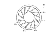
ファン61は、シャフト62の一端部が固定された基部61aと、基部61aの周面61bから延出した複数のブレード61cとを有している。ファン61は、合成樹脂材料あるいは金属材料で構成される。基部61aは、カップ状に形成され、その開口部が壁部3mに向いた姿勢で配置されている。基部61aは、円板状の基壁部61fと、この基壁部61fの周縁部から壁部3mへ向けて延出した側壁部61gとを有している。側壁部61gの外周面が、基部61aの周面61bである。基壁部61fの内面には、凹状の軸固定部61hが設けられており、この軸固定部61hにシャフト62の一端部が挿入して固定されている。   The fan 61 includes a base portion 61a to which one end portion of the shaft 62 is fixed, and a plurality of blades 61c extending from the peripheral surface 61b of the base portion 61a. The fan 61 is made of a synthetic resin material or a metal material. The base 61a is formed in a cup shape, and the opening is arranged in a posture facing the wall 3m. The base portion 61a includes a disk-shaped base wall portion 61f and a side wall portion 61g extending from the peripheral edge portion of the base wall portion 61f toward the wall portion 3m. The outer peripheral surface of the side wall portion 61g is the peripheral surface 61b of the base portion 61a. A concave shaft fixing portion 61h is provided on the inner surface of the base wall portion 61f, and one end portion of the shaft 62 is inserted and fixed to the shaft fixing portion 61h.

また、ファン61は、図4に示されるように、その外周部に円環状の接続部材61dを有している。接続部材61dは、複数のブレード61cの軸方向側の外縁部同士を接続している。また、ブレード61cの端部61eは、その内周部から外周部に向かうにしたがい、壁部51aから離間するように湾曲(傾斜)して形成されている。   Further, as shown in FIG. 4, the fan 61 has an annular connection member 61 d on the outer peripheral portion thereof. The connection member 61d connects the outer edge portions on the axial direction side of the plurality of blades 61c. Further, the end 61e of the blade 61c is formed to be curved (inclined) so as to be separated from the wall 51a as it goes from the inner periphery to the outer periphery.

軸受部53は、ケース部品51に固定されたベース部品63に設けられ、シャフト62を回転可能に支持している。ベース部品63は、ケース部品51に、例えば接着やねじ止め等されることで固定される(取り付けられる)。なお、ベース部品63は、ケース部品51と一体成形することもできる。軸受部53は、円筒状に形成されている。軸受部53は、例えば、ニードル軸受、ボール軸受、すべり軸受、流体軸受、含油軸受等として構成することができる。軸受部53は、ベース部品63の基部63aに立設された円筒部51iの筒内に形成された開口部51pに嵌合されて基部63aに固定されている。また、円筒部51iの底面には、スラスト板55が固定されている。スラスト板55は、シャフト62の軸方向の端面を支持する。基部63aに設けられた軸受部53の開口部51pには、シャフト62の少なくとも一部が収容されている。軸受部53は、回転部としての回転体52の少なくとも一部が収容され該回転体52が回転可能に支持された支持部の一例である。   The bearing portion 53 is provided on a base component 63 fixed to the case component 51, and supports the shaft 62 in a rotatable manner. The base part 63 is fixed (attached) to the case part 51 by, for example, bonding or screwing. Note that the base component 63 can be integrally formed with the case component 51. The bearing portion 53 is formed in a cylindrical shape. The bearing portion 53 can be configured as, for example, a needle bearing, a ball bearing, a slide bearing, a fluid bearing, or an oil-impregnated bearing. The bearing portion 53 is fitted into an opening 51p formed in a cylinder of a cylindrical portion 51i provided upright on the base portion 63a of the base component 63, and is fixed to the base portion 63a. A thrust plate 55 is fixed to the bottom surface of the cylindrical portion 51i. The thrust plate 55 supports the end surface of the shaft 62 in the axial direction. At least a part of the shaft 62 is accommodated in the opening 51p of the bearing 53 provided in the base 63a. The bearing portion 53 is an example of a support portion in which at least a part of the rotating body 52 as a rotating portion is accommodated and the rotating body 52 is rotatably supported.

モータ部54は、図3に示されるように、ステータ54aと、ステータ54aを囲繞したロータ54bと、回路基板54cと、を有する。ステータ54aは、巻線54dを装着した鉄心54eを有する。ロータ54bは、円筒状のヨーク54fと、ヨーク54fの内周面に周方向に沿って相互に間隔をあけて固定された複数の磁石54gと、を有する。ヨーク54fは、基部61aの側壁部61gの内周側に固定されている。回路基板54cには、リード線56が接続されており、回路基板54cは、リード線56から供給される電力を巻線54dに伝える。モータ部54は、磁石54gと、この磁石54gに対向するステータ54aの電磁作用により、ロータ54bが回転するようになっており、ロータ54bの回転によって回転体52が回転する。   As shown in FIG. 3, the motor unit 54 includes a stator 54a, a rotor 54b surrounding the stator 54a, and a circuit board 54c. The stator 54a has an iron core 54e fitted with a winding 54d. The rotor 54b includes a cylindrical yoke 54f and a plurality of magnets 54g fixed to the inner peripheral surface of the yoke 54f at intervals along the circumferential direction. The yoke 54f is fixed to the inner peripheral side of the side wall portion 61g of the base portion 61a. A lead wire 56 is connected to the circuit board 54c, and the circuit board 54c transmits power supplied from the lead wire 56 to the winding 54d. In the motor unit 54, the rotor 54b is rotated by the electromagnetic action of the magnet 54g and the stator 54a facing the magnet 54g, and the rotating body 52 is rotated by the rotation of the rotor 54b.

また、ファンユニット50Aには、軸受部53から離脱する方向への回転体52の移動を規制する移動規制構造57(抜止部、抜止構造、抜止機構)が設けられている。移動規制構造57は、回転体52に設けられた当接部58(支持部)と、壁部3mに設けられた規制部59(支持部)と、を有する。 The fan unit 50 </ b> A is provided with a movement restricting structure 57 (a retaining portion, a retaining structure, a retaining mechanism) that restricts the movement of the rotating body 52 in the direction away from the bearing portion 53. The movement restricting structure 57 includes a contact portion 58 (support portion) provided on the rotating body 52 and a restricting portion 59 (support portion) provided on the wall portion 3m .

当接部58は、基部61aに設けられている。詳細には、基部61aの基壁部61fの中央部の外面が当接部58を構成している。   The contact portion 58 is provided on the base portion 61a. Specifically, the outer surface of the central portion of the base wall portion 61 f of the base portion 61 a constitutes the contact portion 58.

規制部59は、突出部59a(突起)と支持部59bとを有す。突出部59aは、支持部59bから当接部58に向けて筐体内側に突出している。突出部59aは、当接部58に接離可能となっている。 Regulating portion 59, that have a and a support portion 59b butt out section 59a (projections). Collision detection section 59a protrudes to the housing side from the support portion 59b toward the abutment portion 58. Collision detection section 59a has a movable toward and away from the contact portion 58.

ここで、通常は、ステータ54aに対する磁石54gの引力(磁力)によって、回転体52は、突出部59aと当接部58との間の規定距離を維持した状態で回転や停止をしているが、ファンユニット50Aに外力等が加わって、その引力に抗して回転体52が軸受部53から離脱する方向へ移動することがある。このように、ファンユニット50Aに衝撃が加わって、回転体52が軸受部53から離脱する方向へ移動した場合、回転体52に設けられた当接部58がケース部品51に設けられた規制部59に当接する。これにより、規制部59が、軸受部53から離脱する方向への回転体52の移動を規制する。別の言い方をすると、規制部59は、当接部58と当接することで開口部51pから離脱する方向への柱部としてのシャフト62の移動を抑制する。そして、外力等の影響が無くなると、磁石54gの引力(磁力)によって、回転体52は、突出部59aと当接部58との間の規定距離を確保した位置に復帰する。このように、本実施形態では、回転体52の軸方向に沿った移動を規制する。   Here, normally, the rotating body 52 is rotated or stopped in a state where the specified distance between the protruding portion 59a and the contact portion 58 is maintained by the attractive force (magnetic force) of the magnet 54g with respect to the stator 54a. In some cases, an external force or the like is applied to the fan unit 50 </ b> A, and the rotating body 52 moves in a direction of separating from the bearing portion 53 against the attractive force. Thus, when an impact is applied to the fan unit 50 </ b> A and the rotator 52 moves in a direction away from the bearing portion 53, the contact portion 58 provided on the rotator 52 is a restricting portion provided on the case component 51. 59 abuts. Thereby, the restricting portion 59 restricts the movement of the rotating body 52 in the direction away from the bearing portion 53. In other words, the restricting portion 59 abuts on the abutting portion 58 to suppress the movement of the shaft 62 as the column portion in the direction away from the opening 51p. When the influence of the external force or the like disappears, the rotating body 52 returns to the position where the specified distance between the protruding portion 59a and the contact portion 58 is secured by the attractive force (magnetic force) of the magnet 54g. Thus, in the present embodiment, the movement of the rotating body 52 along the axial direction is restricted.

また、本実施形態では、一例として、図3,5に示されるように、筐体3Aの壁部3mには、壁部51cの一部(突出側の端部)を覆う壁部3v(覆部)が突出されている。壁部3vは、壁部51cと壁部3mとの間の隙間を覆っている。よって、本実施形態によれば、一例としては、当該隙間から空気が漏れるのが抑制される。よって、一例としては、ファンユニット50Aの動作(ファン61の回転)における動作効率、ひいては冷却効率が低下するのが抑制される。また、壁部3vは、ケース部品51(ファンユニット50A)を筐体3Aに設ける際の、位置決め部(ガイド部)としても機能する。また、かかる構造は、換言すれば、ファンユニット50Aの側壁部(第三の壁部)が、ケース部品51の壁部51cと筐体3Aの壁部3vとが、回転軸Axの軸方向に重なって構成されているということができる。このように、壁部51c,3vが重なった構成により、この部分の空気抵抗が増大し、空気が抜けにくくなる。   In the present embodiment, as an example, as shown in FIGS. 3 and 5, the wall 3 m of the housing 3 </ b> A has a wall 3 v (covering a part of the wall 51 c (end on the protruding side)). Part) is projected. The wall 3v covers the gap between the wall 51c and the wall 3m. Therefore, according to this embodiment, as an example, air leakage from the gap is suppressed. Therefore, as an example, it is possible to suppress a reduction in the operating efficiency in the operation of the fan unit 50A (the rotation of the fan 61), and hence the cooling efficiency. The wall portion 3v also functions as a positioning portion (guide portion) when the case component 51 (fan unit 50A) is provided in the housing 3A. In other words, in this structure, the side wall (third wall) of the fan unit 50A is such that the wall 51c of the case component 51 and the wall 3v of the housing 3A are in the axial direction of the rotation axis Ax. It can be said that they are configured to overlap. Thus, by the structure which wall part 51c, 3v overlapped, the air resistance of this part increases and it becomes difficult to escape air.

以上、説明したように、本実施形態では、一例として、ファンユニット50Aのケースが、テレビジョン受像機1Aの筐体3Aの壁部3mによって構成された。よって、本実施形態によれば、一例としては、ファンユニット50Aの部品点数を減らしたり、ファンユニット50Aの構成を簡素化したりすることができる。また、本実施形態によれば、一例としては、ファンユニット50Aの厚さをより薄くすることができ、よって、一例としては、筐体3Aの厚さをより薄くすることができる。   As described above, in the present embodiment, as an example, the case of the fan unit 50A is configured by the wall 3m of the housing 3A of the television receiver 1A. Therefore, according to this embodiment, as an example, the number of parts of the fan unit 50A can be reduced, or the configuration of the fan unit 50A can be simplified. Further, according to the present embodiment, as an example, the thickness of the fan unit 50A can be made thinner, and as an example, the thickness of the housing 3A can be made thinner.

<第2実施形態>
本実施形態にかかるテレビジョン受像機1Bでは、ファンユニット50Bは、一例として、図6に示されるように、モータ部54およびファン61を支持するベース部品63が、ケース部品51ではなく、筐体3Bの壁部3mに固定されている。ベース部品63は、壁部3mに、例えば接着やねじ止め等することで、固定される(取り付けられる)。したがって、本実施形態では、一例として、モータ部54およびファン61の軸方向の向きが、上記第1実施形態にかかるテレビジョン受像機1Aとは、逆になっている。しかしながら、かかる構成によっても、ファンユニット50Bの軸方向の壁部が、筐体3Bの壁部3mとして共用されている。よって、本実施形態によっても、上記第1実施形態と同様の結果(効果)が得られる。
Second Embodiment
In the television receiver 1B according to the present embodiment, as an example, the fan unit 50B includes a base part 63 that supports the motor unit 54 and the fan 61, instead of the case part 51, as shown in FIG. It is fixed to the 3B wall 3m. The base part 63 is fixed (attached) to the wall 3m by, for example, bonding or screwing. Therefore, in this embodiment, as an example, the axial directions of the motor unit 54 and the fan 61 are opposite to those of the television receiver 1A according to the first embodiment. However, even in such a configuration, the axial wall portion of the fan unit 50B is shared as the wall portion 3m of the housing 3B. Therefore, also according to this embodiment, the same result (effect) as that of the first embodiment can be obtained.

<第3実施形態>
本実施形態では、一例として、図7に示されるように、電子機器1Cは、第一筐体3Cと第二筐体2Cとを備える。具体的に、第一筐体3C(第一部分)には、表示装置4の少なくとも一部が収容される。また、第一筐体3Cには、表示装置4と重なって透明なタッチパネル5(タッチセンサ、入力操作部、入力受付部、入力部)が設けられている。ユーザ等は、タッチパネル5を介して表示装置4の表示画面4aに表示される映像(画像)を視認することができる。
<Third Embodiment>
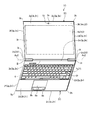
In the present embodiment, as an example, as illustrated in FIG. 7, the electronic device 1 </ b> C includes a first housing 3 </ b> C and a second housing 2 </ b> C. Specifically, at least a part of the display device 4 is accommodated in the first housing 3C (first portion). The first housing 3C is provided with a transparent touch panel 5 (touch sensor, input operation unit, input receiving unit, input unit) that overlaps the display device 4. A user or the like can visually recognize a video (image) displayed on the display screen 4 a of the display device 4 via the touch panel 5.

図7に示されるように、第二筐体2C(第二部分)には、基板6が収容されている。第二筐体2Cには、キーボード7(入力操作部、第一入力操作部、入力受付部、入力部)や、ポインティングデバイス8a(入力操作部、第二入力操作部、入力受付部、入力部)、クリックボタン8b(入力操作部、入力受付部、入力部)等が設けられる。   As shown in FIG. 7, the substrate 6 is accommodated in the second housing 2 </ b> C (second portion). The second casing 2C includes a keyboard 7 (input operation unit, first input operation unit, input reception unit, input unit) and pointing device 8a (input operation unit, second input operation unit, input reception unit, input unit). ), A click button 8b (input operation unit, input receiving unit, input unit) and the like.

第一筐体3Cと第二筐体2Cとは、ヒンジ機構9(ヒンジ部、接続部、連結部、回動支持部、接続機構、連結機構、回動支持機構)によって回動可能に接続されている。第一筐体3Cと第二筐体2Cとは、ヒンジ機構9により、少なくとも図7に示される展開状態と、図示されない折り畳み状態との間で回動可能に接続されている。本実施形態では、一例として、ヒンジ機構9は、第一筐体3Cと第二筐体2Cとを、回動軸Ax2回りに回動可能に、接続している。   The first housing 3C and the second housing 2C are rotatably connected by a hinge mechanism 9 (hinge portion, connection portion, coupling portion, rotation support portion, connection mechanism, connection mechanism, rotation support mechanism). ing. The first housing 3C and the second housing 2C are connected by a hinge mechanism 9 so as to be rotatable at least between a deployed state shown in FIG. 7 and a folded state (not shown). In the present embodiment, as an example, the hinge mechanism 9 connects the first housing 3C and the second housing 2C so as to be rotatable about the rotation axis Ax2.

表示装置4の表示画面4aは、第一筐体3Cの面3a(前面、上面、正面、面部)に設けられた開口部3rを介して視認可能である。また、キーボード7や、ポインティングデバイス8a、クリックボタン8b等は、第二筐体2Cの面2a(前面、上面、正面、面部)に露出している。折り畳み状態では、第一筐体3Cの面3aと第二筐体2Cの面2aとが重なり、表示画面4aや、キーボード7、ポインティングデバイス8a、クリックボタン8b等は、第一筐体3Cおよび第二筐体2Cに隠される。展開状態では、第一筐体3Cの面3aおよび第二筐体2Cの面2aが露出され、表示画面4aや、キーボード7、ポインティングデバイス8a、クリックボタン8b等は、使用可能(視認可能あるいは操作可能)になる。なお、第一筐体3Cの厚さ方向の一方がタッチパネルの面で覆われる場合もある。その場合、タッチパネルの面が第一筐体の面である。また、第二筐体2Cにキーボードに替えてタッチパネル付きの表示装置(図示されず)が設けられる場合もある。さらに、第二筐体2Cの厚さ方向の一方がタッチパネルの面で覆われる場合もある。その場合、タッチパネルの面が第二筐体の面である。   The display screen 4a of the display device 4 is visible through an opening 3r provided on the surface 3a (front surface, upper surface, front surface, surface portion) of the first housing 3C. In addition, the keyboard 7, the pointing device 8a, the click button 8b, and the like are exposed on the surface 2a (front surface, upper surface, front surface, surface portion) of the second housing 2C. In the folded state, the surface 3a of the first housing 3C and the surface 2a of the second housing 2C overlap, and the display screen 4a, the keyboard 7, the pointing device 8a, the click button 8b, etc. Hidden in the two cases 2C. In the unfolded state, the surface 3a of the first housing 3C and the surface 2a of the second housing 2C are exposed, and the display screen 4a, the keyboard 7, the pointing device 8a, the click button 8b, and the like can be used (viewed or operated). Possible). Note that one side of the first casing 3C in the thickness direction may be covered with the surface of the touch panel. In that case, the surface of the touch panel is the surface of the first housing. Further, a display device (not shown) with a touch panel may be provided in the second housing 2C instead of the keyboard. Furthermore, one side in the thickness direction of the second housing 2C may be covered with the surface of the touch panel. In that case, the surface of the touch panel is the surface of the second housing.

第一筐体3Cは、本実施形態では、一例として、図7に示されるように、正面視および背面視では四角形状(本実施形態では、一例として長方形状)に構成されている。また、第一筐体3Cは、本実施形態では、一例として、薄い扁平な直方体状に構成されている。第一筐体3Cは、面3aとこの反対側の面3b(後面、下面、背面、面部)と、を有する。面3aと面3bとは略平行である。また、第一筐体3Cは、図7に示されるように、正面視では、四つの端部3c〜3f(辺部、縁部)と、四つの角部3g〜3j(尖部、曲部、端部)と、を有する。端部3c,3eは、長辺部の一例である。また、端部3d,3fは、短辺部の一例である。   In the present embodiment, as an example, the first housing 3 </ b> C is configured in a quadrangular shape (in the present embodiment, a rectangular shape as an example) in the front view and the rear view, as shown in FIG. 7. Further, in the present embodiment, the first housing 3C is configured as a thin flat rectangular parallelepiped as an example. The first housing 3C has a surface 3a and an opposite surface 3b (rear surface, lower surface, back surface, surface portion). The surface 3a and the surface 3b are substantially parallel. In addition, as shown in FIG. 7, the first housing 3 </ b> C has four end portions 3 c to 3 f (side portions, edge portions) and four corner portions 3 g to 3 j (pointed portions, curved portions) in a front view. , End). The end portions 3c and 3e are examples of long side portions. The ends 3d and 3f are examples of short sides.

また、第一筐体3Cは、面3aを有する壁部3k(部分、プレート、フレーム、前壁部、表壁部、天壁部)と、面3bを有する壁部3m(部分、プレート、後壁部、裏壁部、底壁部)と、を有する。壁部3k,3mは、四角形状(本実施形態では、一例として長方形状)である。また、第一筐体3Cは、壁部3kと壁部3mとの間に亘った面3p(側面、周面)を有する四つの壁部3n(部分、プレート、側壁部、端壁部、立壁部、亘部)を有する。なお、壁部3kには、一例としては四角形状の開口部3rが設けられている。よって、壁部3kは、四角形状かつ枠状である。   The first housing 3C includes a wall 3k (part, plate, frame, front wall, front wall, top wall, top wall) having a surface 3a and a wall 3m (part, plate, rear wall) having a surface 3b. Wall, back wall, and bottom wall). The walls 3k and 3m have a quadrangular shape (in this embodiment, a rectangular shape as an example). The first housing 3C includes four wall portions 3n (parts, plates, side wall portions, end wall portions, standing walls) having a surface 3p (side surface, peripheral surface) extending between the wall portions 3k and 3m. Part, span part). The wall 3k is provided with, for example, a quadrangular opening 3r. Therefore, the wall 3k has a rectangular shape and a frame shape.

さらに、第一筐体3Cは、複数の部品(分割体)が組み合わせられて構成されることができる。第一筐体3Cは、本実施形態では、一例として、少なくとも壁部3kを含む第一筐体部材31(第一部分、前側部材、マスク、マスク部、カバー、フロントカバー、カバー部、第一領域)と、少なくとも壁部3mを含む第二筐体部材32(第二部分、後側部材、ベース、ベース部、ボトム、ボトム部、カバー、リヤカバー、カバー部、第二領域)とを有する。壁部3nは、第一筐体部材31および第二筐体部材32のうち少なくともいずれか一方(例えば、第二筐体部材32)に含まれる。また、第一筐体3Cは、第一筐体部材31および第二筐体部材32とは別に、これらの間に位置した第三筐体部材(第三部分、中間部材、隔部材、障壁部材、壁部材、介在部材、インナプレート、ミドルプレート、ミドルフレーム、第三領域、図示されず)や、第四筐体部材(第四部分、中間部材、隔部材、障壁部材、壁部材、介在部材、覆部材、シールド、第四領域、図示されず)等を有することができる。第一筐体3Cは、金属材料や、合成樹脂材料等で構成されることができる。   Furthermore, the first housing 3C can be configured by combining a plurality of components (divided bodies). In this embodiment, as an example, the first housing 3C includes a first housing member 31 including at least a wall 3k (first portion, front member, mask, mask portion, cover, front cover, cover portion, first region). ) And a second housing member 32 (second portion, rear member, base, base portion, bottom, bottom portion, cover, rear cover, cover portion, second region) including at least the wall portion 3m. The wall 3n is included in at least one of the first housing member 31 and the second housing member 32 (for example, the second housing member 32). In addition, the first housing 3C is separated from the first housing member 31 and the second housing member 32, and a third housing member (third portion, intermediate member, separation member, barrier member) positioned between them. , Wall member, interposition member, inner plate, middle plate, middle frame, third region, not shown) and fourth housing member (fourth part, intermediate member, separation member, barrier member, wall member, interposition member) , Covering member, shield, fourth region, not shown) and the like. The first housing 3C can be made of a metal material, a synthetic resin material, or the like.

また、本実施形態では、一例として、表示装置4(表示部、ディスプレイ、パネル)の、面3a側に位置した表示画面4aは、開口部3rを介して第一筐体3Cの前方(外方)に露出している。ユーザ等は、前方側から開口部3rを介して表示画面4aを視認することができる。表示装置4は、正面視では四角形状(本実施形態では一例として長方形状)に構成されている。また、表示装置4は、前後方向に薄い扁平な直方体状に構成されている。表示装置4は、例えば、液晶ディスプレイ(LCD,liquid crystal display)や有機ELディスプレイ(OELD,organic electro-luminescent display)等である。   Moreover, in this embodiment, as an example, the display screen 4a located on the surface 3a side of the display device 4 (display unit, display, panel) is positioned in front of the first housing 3C (outside) through the opening 3r. ) Is exposed. A user or the like can visually recognize the display screen 4a from the front side through the opening 3r. The display device 4 is configured in a quadrangular shape (in the present embodiment, a rectangular shape as an example) when viewed from the front. The display device 4 is configured in a flat rectangular parallelepiped shape that is thin in the front-rear direction. The display device 4 is, for example, a liquid crystal display (LCD), an organic EL display (OELD, organic electro-luminescent display), or the like.

また、本実施形態では、一例として、表示装置4の前側(表側、壁部3k側)には、タッチパネル5(一例としては入力操作パネル、タッチセンサ、操作面、カバー)が設けられている。タッチパネル5は、透明な比較的薄い四角形状に構成され、表示画面4aを覆っている。操作者(ユーザ等)は、例えば、手指や部品(例えばスタイラス等、図示されず)等でタッチパネル5に対して、触れる、押す、擦る、あるいは手指やスタイラス等をタッチパネル5の近傍で動かす等の操作を行うことで、入力処理を実行することができる。また、表示装置4の表示画面4aから出た光は、タッチパネル5を通過して壁部3kの開口部3rから第一筐体3Cの前方(外方)へ出る。   Moreover, in this embodiment, the touch panel 5 (an input operation panel, a touch sensor, an operation surface, a cover as an example) is provided in the front side (front side, wall part 3k side) of the display apparatus 4 as an example. The touch panel 5 is configured in a transparent relatively thin square shape and covers the display screen 4a. An operator (user or the like) touches, pushes, rubs the touch panel 5 with a finger or a component (for example, a stylus, not shown), or moves the finger or the stylus near the touch panel 5. By performing the operation, input processing can be executed. Further, the light emitted from the display screen 4a of the display device 4 passes through the touch panel 5 and exits from the opening 3r of the wall 3k to the front (outward) of the first housing 3C.

第二筐体2Cは、本実施形態では、一例として、図7,8に示されるように、正面視および背面視では四角形状(本実施形態では、一例として長方形状)に構成されている。また、第二筐体2Cは、本実施形態では、一例として、薄い扁平な直方体状に構成されている。第二筐体2Cは、面2aとこの反対側の面2b(後面、下面、背面、面部)と、を有する。面2aと面2bとは略平行である。また、第二筐体2Cは、面2aに対する正面視では、四つの端部2c〜2f(辺部、縁部)と、四つの角部2g〜2j(尖部、曲部、端部)と、を有する。端部2c,2eは、長辺部の一例である。また、端部2d,2fは、短辺部の一例である。   In the present embodiment, as an example, the second housing 2C is configured in a quadrangular shape (in the present embodiment, a rectangular shape as an example) as shown in FIGS. In the present embodiment, the second housing 2C is configured in a thin flat rectangular parallelepiped shape as an example. The second housing 2C includes a surface 2a and an opposite surface 2b (rear surface, lower surface, back surface, surface portion). The surface 2a and the surface 2b are substantially parallel. The second housing 2C has four end portions 2c to 2f (side portions, edge portions) and four corner portions 2g to 2j (pointed portions, curved portions, end portions) in front view with respect to the surface 2a. Have. The ends 2c and 2e are examples of long sides. The ends 2d and 2f are examples of short sides.

また、第二筐体2Cは、面2aを有する壁部2k(部分、プレート、フレーム、前壁部、表壁部、天壁部)と、面2bを有する壁部2m(部分、プレート、後壁部、裏壁部、底壁部)と、を有する。壁部2k,2mは、四角形状(本実施形態では、一例として長方形状)である。また、第二筐体2Cは、壁部2kと壁部2mとの間に亘った面2p(側面、周面)を有する四つの壁部2n(部分、プレート、側壁部、端壁部、立壁部、亘部)を有する。なお、壁部2kには、一例としては四角形状の開口部2rが設けられている。よって、壁部2kは、四角形状かつ枠状である。   The second housing 2C includes a wall 2k (part, plate, frame, front wall, front wall, top wall, top wall) having a surface 2a and a wall 2m (part, plate, rear) having a surface 2b. Wall, back wall, and bottom wall). The walls 2k and 2m have a quadrangular shape (in this embodiment, a rectangular shape as an example). The second housing 2C includes four wall portions 2n (parts, plates, side wall portions, end wall portions, standing walls) having a surface 2p (side surface, peripheral surface) extending between the wall portion 2k and the wall portion 2m. Part, span part). The wall 2k is provided with, for example, a rectangular opening 2r. Therefore, the wall 2k is square and frame-shaped.

さらに、第二筐体2Cは、一例として、複数の部品(分割体)が組み合わせられて構成されることができる。第二筐体2Cは、本実施形態では、一例として、少なくとも壁部2kを含む第一筐体部材21(第一部分、前側部材、マスク、マスク部、カバー、フロントカバー、カバー部、第一領域)と、少なくとも壁部2mを含む第二筐体部材22(第二部分、後側部材、ベース、ベース部、ボトム、ボトム部、カバー、リヤカバー、カバー部、第二領域)とを有する。壁部2nは、第一筐体部材21および第二筐体部材22のうち少なくともいずれか一方(例えば、第二筐体部材22)に含まれる。また、第二筐体2Cは、第一筐体部材21および第二筐体部材22とは別に、これらの間に位置した第三筐体部材(第三部分、中間部材、隔部材、障壁部材、壁部材、介在部材、インナプレート、ミドルプレート、ミドルフレーム、第三領域、図示されず)や、第四筐体部材(第四部分、中間部材、隔部材、障壁部材、壁部材、介在部材、覆部材、シールド、第四領域、図示されず)等を有することができる。第二筐体2Cは、金属材料や、合成樹脂材料等で構成されることができる。   Furthermore, the 2nd housing | casing 2C can be comprised by combining several components (divided body) as an example. In this embodiment, as an example, the second housing 2C includes a first housing member 21 including at least a wall 2k (first portion, front member, mask, mask portion, cover, front cover, cover portion, first region). And a second housing member 22 (second portion, rear member, base, base portion, bottom, bottom portion, cover, rear cover, cover portion, second region) including at least the wall portion 2m. The wall 2n is included in at least one of the first housing member 21 and the second housing member 22 (for example, the second housing member 22). In addition, the second housing 2C is separated from the first housing member 21 and the second housing member 22, and a third housing member (third portion, intermediate member, separation member, barrier member) positioned between them. , Wall member, interposition member, inner plate, middle plate, middle frame, third region, not shown) and fourth housing member (fourth part, intermediate member, separation member, barrier member, wall member, interposition member) , Covering member, shield, fourth region, not shown) and the like. The second housing 2C can be made of a metal material, a synthetic resin material, or the like.

また、本実施形態では、一例として、キーボード7の操作面7a(面、上面)は、開口部2rを介して第二筐体2Cの前方(外方)に露出している。面2aにおいて、キーボード7は、端部2e側に寄せて位置され、ポインティングデバイス8aならびにクリックボタン8bは端部2eとは反対側の端部2c側に寄せて配置されている。端部2eは奥行方向(前後方向)の奥側に位置され、端部2cは手前側に位置されている。   In the present embodiment, as an example, the operation surface 7a (surface, upper surface) of the keyboard 7 is exposed to the front (outward) of the second housing 2C through the opening 2r. On the surface 2a, the keyboard 7 is positioned close to the end 2e, and the pointing device 8a and the click button 8b are disposed close to the end 2c opposite to the end 2e. The end 2e is located on the back side in the depth direction (front-rear direction), and the end 2c is located on the near side.

そして、本実施形態では、一例として、図7に示されるように、第二筐体2C内には、キーボード7の後側(裏側、背後側、壁部2m側、操作面7aとは反対側)に、一つ以上の基板6(回路基板、制御基板、メイン基板、電気部品、第一電気部品)が収容されている。基板6は、キーボード7と並行して設けられている。基板6は、壁部2k,2m,2n等と離間した状態で、すなわち、壁部2k,2m,2n等との間に空間(隙間)が形成された状態で、設けられている。   In the present embodiment, as an example, as shown in FIG. 7, in the second housing 2 </ b> C, the rear side of the keyboard 7 (the back side, the back side, the wall 2 m side, the side opposite to the operation surface 7 a). ) Accommodates one or more boards 6 (circuit board, control board, main board, electrical component, first electrical component). The substrate 6 is provided in parallel with the keyboard 7. The substrate 6 is provided in a state of being separated from the wall portions 2k, 2m, 2n and the like, that is, in a state where a space (gap) is formed between the walls 2k, 2m, 2n and the like.

また、本実施形態では、一例として、基板6には、例えば、CPU(central processing unit)や、グラフィックコントローラ、電源回路部品、PCH(platform controller hub)、メモリスロットコネクタ、LCDコネクタ、I/O(input/output)コネクタ、電源コイル、素子、コネクタ等の複数の部品(図示されず)を実装することができる。また、制御回路は、例えば、映像信号処理回路や、チューナ部、HDMI(high-definition multimedia interface)信号処理部、AV(audio video)入力端子、リモコン信号受信部、制御部、セレクタ、オンスクリーンディスプレイインタフェース、記憶部(例えば、ROM(read only memory)、RAM(random access memory)、HDD(hard disk drive)、SSD(solid state drive)等)、音声信号処理回路等を、含むことができる。制御回路は、表示装置4の表示画面4aでの映像(動画や静止画等)の出力や、スピーカ(図示されず)での音声の出力、LED(light emitting diode、図示されず)での発光等を制御する。表示装置4や、スピーカ、LED等は、出力部の一例である。   In this embodiment, as an example, the substrate 6 includes, for example, a central processing unit (CPU), a graphic controller, a power supply circuit component, a PCH (platform controller hub), a memory slot connector, an LCD connector, an I / O (I / O). A plurality of components (not shown) such as input / output) connectors, power supply coils, elements, and connectors can be mounted. The control circuit includes, for example, a video signal processing circuit, a tuner unit, an HDMI (high-definition multimedia interface) signal processing unit, an AV (audio video) input terminal, a remote control signal receiving unit, a control unit, a selector, an on-screen display An interface, a storage unit (for example, ROM (read only memory), RAM (random access memory), HDD (hard disk drive), SSD (solid state drive), etc.), an audio signal processing circuit, and the like can be included. The control circuit outputs video (moving images, still images, etc.) on the display screen 4a of the display device 4, outputs audio from a speaker (not shown), and emits light from an LED (light emitting diode, not shown). Control etc. The display device 4, the speaker, the LED, and the like are examples of the output unit.

また、本実施形態では、一例として、図8に示されるように、壁部2m(第一の壁部)には、スリット状に開口され、放射状かつ円形状に配置された複数の通気口2sが設けられている。ファンユニット50Cは、第二筐体2C内で、通気口2sと第二筐体2Cの厚さ方向に重なった位置、すなわち端部2eの近傍に、設けられている。   In the present embodiment, as an example, as shown in FIG. 8, a plurality of vent holes 2 s opened in a slit shape in the wall portion 2 m (first wall portion) and arranged radially and circularly. Is provided. The fan unit 50C is provided in the second housing 2C at a position overlapping the vent 2s and the second housing 2C in the thickness direction, that is, in the vicinity of the end 2e.

図9を図3と比較すれば明らかとなるように、本実施形態にかかるファンユニット50Cの構造は、上記第1実施形態にかかるファンユニット50Aの構造と同様である。よって、本実施形態によっても、上記第1実施形態と同様の構成に基づく同様の結果(効果)が得られる。   As will be apparent by comparing FIG. 9 with FIG. 3, the structure of the fan unit 50C according to the present embodiment is the same as the structure of the fan unit 50A according to the first embodiment. Therefore, also according to this embodiment, the same result (effect) based on the same configuration as that of the first embodiment can be obtained.

また、本実施形態では、一例として、図9に示されるように、壁部51cと壁部2m(第一の壁部)との間には、弾性部材64(可撓性部材、シール部材、覆部材、覆部)が設けられている。弾性部材64は、一例としては、合成樹脂材料(例えば、発泡性の樹脂材料、スポンジ等)や、エラストマ(例えば、合成ゴム)等の、可撓性かつ弾性を有した部材で構成される。弾性部材64は、壁部51cと壁部2mとの間の隙間を覆い、この隙間をシールしている。よって、当該隙間から空気が漏れるのが抑制される。よって、一例としては、ファンユニット50Cの動作(ファン61の回転)における動作効率、ひいては冷却効率が低下するのが抑制される。また、弾性部材64は、可撓性あるいは弾性を有するため、壁部51cとの位置ずれが生じた場合にあっても、壁部51cとの間をシールすることができる。また、弾性力によって接触部分の面圧が高まりやすくなり、シール性能がより高まりやすい。   In the present embodiment, as an example, as shown in FIG. 9, an elastic member 64 (a flexible member, a seal member, a wall between the wall 51c and the wall 2m (first wall)). A covering member and a covering portion) are provided. As an example, the elastic member 64 is configured by a flexible and elastic member such as a synthetic resin material (for example, foamable resin material, sponge, or the like) or an elastomer (for example, synthetic rubber). The elastic member 64 covers the gap between the wall 51c and the wall 2m and seals this gap. Therefore, the leakage of air from the gap is suppressed. Therefore, as an example, it is possible to suppress a reduction in the operating efficiency in the operation of the fan unit 50C (the rotation of the fan 61), and hence the cooling efficiency. Further, since the elastic member 64 has flexibility or elasticity, it can seal between the wall 51c even when a positional deviation occurs with respect to the wall 51c. Further, the surface pressure of the contact portion is likely to increase due to the elastic force, and the sealing performance is likely to increase.

また、本実施形態では、一例として、図9に示されるように、壁部2mのファンユニット50Cと重なった部分は、第二筐体2Cの筐体外側に膨出され(屈曲され、曲げられ)、剛性が高められている。なお、壁部51aに、通気口を設けることも可能である。また、本実施形態にかかる電子機器1Cには、上記第2実施形態と同様の構成のファンユニット50Bを適用することも可能である。   Further, in the present embodiment, as an example, as shown in FIG. 9, the portion of the wall 2m that overlaps the fan unit 50C is bulged (bent and bent) outside the housing of the second housing 2C. ), Rigidity is enhanced. It is also possible to provide a vent in the wall 51a. In addition, the fan unit 50B having the same configuration as that of the second embodiment can be applied to the electronic apparatus 1C according to the present embodiment.

<第1変形例>
図10を図9と比較すれば明らかとなるように、本変形例にかかる電子機器1Dの第二筐体2Dに収容されたファンユニット50Dの構造は、上記第3実施形態にかかるファンユニット50Cの構造と同様である。よって、本実施形態によっても、上記第3実施形態と同様の構成に基づく同様の結果(効果)が得られる。
<First Modification>
As will be apparent from comparing FIG. 10 with FIG. 9, the structure of the fan unit 50D housed in the second housing 2D of the electronic apparatus 1D according to this modification is the same as that of the fan unit 50C according to the third embodiment. This is the same as the structure. Therefore, according to this embodiment, the same result (effect) based on the same configuration as that of the third embodiment can be obtained.

ただし、本実施形態では、一例として、図10に示されるように、壁部2mに補強部2t,2uが設けられている。補強部2tは、他の部分より厚さが増大された厚肉部である。また、補強部2uは、壁部2mの筐体外側に突出された壁部(リブ、突出部)である。壁部2mには、このような補強部2t,2uを適宜に設けることができる。なお、補強部は、壁部2mの筐体内側に設けることも可能である。   However, in the present embodiment, as an example, as illustrated in FIG. 10, reinforcing portions 2 t and 2 u are provided on the wall portion 2 m. The reinforcing part 2t is a thick part whose thickness is increased from other parts. Moreover, the reinforcement part 2u is a wall part (rib, protrusion part) protruded outside the housing | casing of the wall part 2m. Such reinforcing portions 2t and 2u can be appropriately provided on the wall portion 2m. The reinforcing part can also be provided inside the housing of the wall 2m.

<第2変形例>
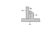
本変形例では、図11に示されるように、ケース部品51の壁部51cの、ファン61(回動軸Ax、図9参照)とは反対側(図11の右側)に、壁部2v(覆部)が設けられている。そして、壁部51cと壁部2vとの間に、弾性部材64(可撓性部材、シール部材、覆部材、覆部)が設けられている。このような構成によっても、上記第3実施形態と同様の結果(効果)が得られる。
<Second Modification>
In this modified example, as shown in FIG. 11, the wall 2v (on the right side in FIG. 11) on the opposite side (right side in FIG. 11) of the wall 51c of the case component 51 from the fan 61 (rotation axis Ax, see FIG. 9) A cover) is provided. An elastic member 64 (a flexible member, a seal member, a cover member, and a cover) is provided between the wall 51c and the wall 2v. Even with such a configuration, the same result (effect) as in the third embodiment can be obtained.

<第3変形例>
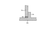
本変形例では、図12に示されるように、ケース部品51の壁部51cと壁部2mとの間に弾性部材64が設けられている。さらに、弾性部材64は、壁部2vにも当接されている。このような構成によっても、上記第3実施形態や第2変形例と同様の結果(効果)が得られる。弾性部材64は、組み立て前に、壁部51cおよび壁部2m,2vのうち一方に接着等によって取り付けておくことができる。
<Third Modification>
In this modification, as shown in FIG. 12, an elastic member 64 is provided between the wall 51c and the wall 2m of the case component 51. Further, the elastic member 64 is also in contact with the wall 2v. Even with such a configuration, the same results (effects) as in the third embodiment and the second modification can be obtained. The elastic member 64 can be attached to one of the wall 51c and the walls 2m, 2v by bonding or the like before assembly.

<第4変形例>
本変形例では、図13に示されるように、移動規制構造57の構成が上記他の実施形態や他の変形例とは異なっている。具体的には、移動規制構造57は、シャフト62に設けられた円環状の当接部58(支持部)と、円筒部51iに設けられた内向きかつ円環状の当接部65(支持部)によって、構成されている。このような構成によれば、一例としては、壁部51c,3m,2mに突出部59aを設けた場合に比べて、ファンユニットの厚さ、ひいては筐体の厚さがより薄くなりやすい。
<Fourth Modification>
In this modification, as shown in FIG. 13, the configuration of the movement restricting structure 57 is different from the other embodiments and other modifications. Specifically, the movement restricting structure 57 includes an annular contact portion 58 (support portion) provided on the shaft 62 and an inward and annular contact portion 65 (support portion) provided on the cylindrical portion 51i. ). According to such a configuration, as an example, the thickness of the fan unit, and hence the thickness of the housing, is likely to be thinner than when the protrusions 59a are provided on the walls 51c, 3m, and 2m.

<第5変形例>
本変形例では、図14に示されるように、移動規制構造57の構成が上記他の実施形態や他の変形例とは異なっている。具体的には、移動規制構造57は、シャフト62を貫通した状態に設けられた棒状の当接部58と、円筒部51iに設けられた内向きかつ円環状の当接部65によって、構成されている。このような構成によっても、一例としては、壁部51c,3m,2mに突出部59aを設けた場合に比べて、ファンユニットの厚さ、ひいては筐体の厚さがより薄くなりやすい。
<Fifth Modification>
In this modification, as shown in FIG. 14, the configuration of the movement restricting structure 57 is different from the other embodiments and other modifications. Specifically, the movement restricting structure 57 is configured by a rod-like contact portion 58 provided so as to penetrate the shaft 62 and an inward and annular contact portion 65 provided on the cylindrical portion 51i. ing. Even with such a configuration, as an example, the thickness of the fan unit, and hence the thickness of the housing, is likely to be thinner than when the protruding portions 59a are provided on the walls 51c, 3m, and 2m.

以上、本発明の実施形態を例示したが、上記実施形態はあくまで一例であって、発明の範囲を限定することは意図していない。これら実施形態は、その他の様々な形態で実施されることが可能であり、発明の要旨を逸脱しない範囲で、種々の省略、置き換え、組み合わせ、変更を行うことができる。これら実施形態は、発明の範囲や要旨に含まれるとともに、特許請求の範囲に記載された発明とその均等の範囲に含まれる。また、各実施形態の構成や形状は、部分的に入れ替えて実施することも可能である。また、各構成や形状等のスペック(構造や、種類、方向、形状、大きさ、長さ、幅、厚さ、高さ、数、配置、位置、材質等)は、適宜に変更して実施することができる。また、ファンユニットが筐体ではなく基板に設けられる構成にも、本発明の構成を適用することができる。   As mentioned above, although embodiment of this invention was illustrated, the said embodiment is an example to the last, Comprising: It is not intending limiting the range of invention. These embodiments can be implemented in various other forms, and various omissions, replacements, combinations, and changes can be made without departing from the scope of the invention. These embodiments are included in the scope and gist of the invention, and are included in the invention described in the claims and the equivalents thereof. In addition, the configuration and shape of each embodiment can be partially exchanged. In addition, specifications (structure, type, direction, shape, size, length, width, thickness, height, number, arrangement, position, material, etc.) of each configuration and shape, etc. are changed as appropriate. can do. The configuration of the present invention can also be applied to a configuration in which the fan unit is provided on the substrate instead of the housing.

1A,1B…テレビジョン受像機(電子機器)、1C,1D…電子機器、2C,2D…第二筐体(筐体)、2m,3m…壁部(第一の壁部)、2s…通気口、2t,2u…補強部、2v,3v…壁部(覆部、第二の部分)、3A…筐体、3s…通気口、51a…壁部(第二の壁部)、51c…壁部(第三の壁部、第一の部分)、61…ファン、64…弾性部材(可撓性部材、シール部材、覆部)。   1A, 1B ... Television receiver (electronic device), 1C, 1D ... electronic device, 2C, 2D ... second housing (housing), 2m, 3m ... wall (first wall), 2s ... ventilation Mouth, 2t, 2u ... reinforcement part, 2v, 3v ... wall part (covering part, second part), 3A ... casing, 3s ... vent, 51a ... wall part (second wall part), 51c ... wall (Third wall, first part), 61... Fan, 64... Elastic member (flexible member, seal member, cover).

Claims (7)

筐体と、
前記筐体内で回転可能に設けられたファンと、
前記ファンと重なった通気口が設けられ前記ファンが収容された空間を構成するととも
に前記ファンに面した前記筐体の第一の壁部と、
前記第一の壁部とは別体であり、前記第一の壁部より前記筐体内側で前記ファンの前記
第一の壁部とは反対側に位置され、当該第一の壁部に取り付けられ、前記ファンが収容さ
れた空間を構成するとともに前記ファンに面した第二の壁部と、
前記第一の壁部と前記第二の壁部との間に亘った第三の壁部と、
を備え、
前記第三の壁部は、前記第二の壁部から一体的に突出し、
前記第三の壁部の前記第一の壁部側の端部と前記第一の壁部との間の隙間を覆う覆部が
設けられた、電子機器。
A housing,
A fan provided rotatably in the housing;
A first wall portion of the housing facing the fan and having a space in which a vent hole overlapping the fan is provided and the fan is accommodated;
The first wall portion is separate from the first wall portion, is located on the opposite side of the fan from the first wall portion on the inner side of the housing, and is attached to the first wall portion. A second wall portion that constitutes a space in which the fan is accommodated and faces the fan;
A third wall portion between the first wall portion and the second wall portion;
With
The third wall portion protrudes integrally from the second wall portion,
A covering portion covering a gap between the first wall portion side end portion of the third wall portion and the first wall portion;
Electronic equipment provided .
前記覆部は、前記第一の壁部の前記筐体内側の面に沿って延びた、請求項に記載の電
子機器。
The covering portion, the first wall portion of said extending along the surface of the housing side, the electronic device according to claim 1.
前記覆部として可撓性部材を備えた、請求項またはに記載の電子機器。 The electronic device of Claim 1 or 2 provided with the flexible member as the said cover part. 前記覆部として前記第三の壁部の前記第一の壁部側の端部と当該第一の壁部との間に挟
まれたシール部材を備えた、請求項のうちいずれか一つに記載の電子機器。
With a seal member sandwiched between said third end of said first wall portion side of the wall and the said first wall portion as the covering portion, either one of claims 1 to 3, The electronic device according to one.
前記第一の壁部は、補強部を有した、請求項1〜のうちいずれか一つに記載の電子機
器。
It said first wall portion had a reinforcing portion, the electronic apparatus according to any one of claims 1-4.
前記ファンは、前記第二の壁部に回転可能に支持された、請求項1〜のうちいずれか
一つに記載の電子機器。
The fan, the second is supported rotatably on the wall portion, the electronic apparatus according to any one of claims 1-5.
前記ファンは、前記第一の壁部に回転可能に支持された、請求項1〜のうちいずれか
一つに記載の電子機器。
The fan, the rotatably supported on the first wall portion, the electronic apparatus according to any one of claims 1-5.
JP2012102637A 2012-04-27 2012-04-27 Electronics Active JP5378564B2 (en)

Priority Applications (2)

Application Number Priority Date Filing Date Title
JP2012102637A JP5378564B2 (en) 2012-04-27 2012-04-27 Electronics
US13/727,881 US20130286297A1 (en) 2012-04-27 2012-12-27 Television receiver and electronic device

Applications Claiming Priority (1)

Application Number Priority Date Filing Date Title
JP2012102637A JP5378564B2 (en) 2012-04-27 2012-04-27 Electronics

Publications (2)

Publication Number Publication Date
JP2013232720A JP2013232720A (en) 2013-11-14
JP5378564B2 true JP5378564B2 (en) 2013-12-25

Family

ID=49476964

Family Applications (1)

Application Number Title Priority Date Filing Date
JP2012102637A Active JP5378564B2 (en) 2012-04-27 2012-04-27 Electronics

Country Status (2)

Country Link
US (1) US20130286297A1 (en)
JP (1) JP5378564B2 (en)

Families Citing this family (2)

* Cited by examiner, † Cited by third party
Publication number Priority date Publication date Assignee Title
US11839050B2 (en) * 2017-08-17 2023-12-05 Compal Electronics, Inc. Heat dissipation module and electronic device
US11665852B2 (en) * 2021-09-10 2023-05-30 Dell Products L.P. Information handling system fan having a concave housing

Family Cites Families (7)

* Cited by examiner, † Cited by third party
Publication number Priority date Publication date Assignee Title
KR20030069611A (en) * 2002-02-22 2003-08-27 엘지전자 주식회사 Device of vibrated reduction of fan
JP2007149007A (en) * 2005-11-30 2007-06-14 Toshiba Corp Electronics
JP2007172328A (en) * 2005-12-22 2007-07-05 Toshiba Corp Electronics
JP2007207944A (en) * 2006-01-31 2007-08-16 Toshiba Corp Electronics
JP4693924B2 (en) * 2009-09-30 2011-06-01 株式会社東芝 Electronics
JP4823374B1 (en) * 2010-05-11 2011-11-24 株式会社東芝 Electronics
JP4929377B2 (en) * 2010-06-18 2012-05-09 株式会社東芝 Television receiver and electronic device

Also Published As

Publication number Publication date
JP2013232720A (en) 2013-11-14
US20130286297A1 (en) 2013-10-31

Similar Documents

Publication Publication Date Title
JP5941740B2 (en) Electronic equipment
JP5342035B1 (en) Electronics
JP5417477B2 (en) Electronics
JP2013251721A (en) Television receiver and electronic apparatus
JP5349641B2 (en) Electronics
JP5330446B2 (en) Electronics and fans
JP5367863B2 (en) Electronics
JPWO2014141443A1 (en) Electronics and touchpad assembly
JP2012004983A (en) Electronic apparatus
JP5378564B2 (en) Electronics
JP2013232777A (en) Television receiver and electronic apparatus
JP2015207061A (en) Electronics
JP5417460B2 (en) Input reception unit and electronic equipment
JP2014086341A (en) Electronic device
JP5395924B2 (en) Electronics
JP6342264B2 (en) Hinge device
JP5492286B2 (en) Electronics
CN104951006B (en) A kind of electronic equipment
JP5175962B1 (en) Television receiver and electronic device
JP2013251640A (en) Television receiver and electronic apparatus
JP6028447B2 (en) Electronic equipment
JP2013242920A (en) Electronic apparatus
JP5162045B2 (en) Electronics
JP5073115B2 (en) Electronics
JP2013225268A (en) Electronic device

Legal Events

Date Code Title Description
TRDD Decision of grant or rejection written
A61 First payment of annual fees (during grant procedure)

Free format text: JAPANESE INTERMEDIATE CODE: A61

Effective date: 20130925

R151 Written notification of patent or utility model registration

Ref document number: 5378564

Country of ref document: JP

Free format text: JAPANESE INTERMEDIATE CODE: R151

S111 Request for change of ownership or part of ownership

Free format text: JAPANESE INTERMEDIATE CODE: R313117

Free format text: JAPANESE INTERMEDIATE CODE: R313121

R350 Written notification of registration of transfer

Free format text: JAPANESE INTERMEDIATE CODE: R350