JP5373373B2 - Lamp device - Google Patents
Lamp device Download PDFInfo
- Publication number
- JP5373373B2 JP5373373B2 JP2008297196A JP2008297196A JP5373373B2 JP 5373373 B2 JP5373373 B2 JP 5373373B2 JP 2008297196 A JP2008297196 A JP 2008297196A JP 2008297196 A JP2008297196 A JP 2008297196A JP 5373373 B2 JP5373373 B2 JP 5373373B2
- Authority
- JP
- Japan
- Prior art keywords
- axis
- light
- reflecting mirror
- light emitting
- prism
- Prior art date
- Legal status (The legal status is an assumption and is not a legal conclusion. Google has not performed a legal analysis and makes no representation as to the accuracy of the status listed.)
- Expired - Fee Related
Links
Images


Classifications
-
- H—ELECTRICITY
- H01—ELECTRIC ELEMENTS
- H01J—ELECTRIC DISCHARGE TUBES OR DISCHARGE LAMPS
- H01J61/00—Gas-discharge or vapour-discharge lamps
- H01J61/84—Lamps with discharge constricted by high pressure
- H01J61/86—Lamps with discharge constricted by high pressure with discharge additionally constricted by close spacing of electrodes, e.g. for optical projection
-
- G—PHYSICS
- G03—PHOTOGRAPHY; CINEMATOGRAPHY; ANALOGOUS TECHNIQUES USING WAVES OTHER THAN OPTICAL WAVES; ELECTROGRAPHY; HOLOGRAPHY
- G03B—APPARATUS OR ARRANGEMENTS FOR TAKING PHOTOGRAPHS OR FOR PROJECTING OR VIEWING THEM; APPARATUS OR ARRANGEMENTS EMPLOYING ANALOGOUS TECHNIQUES USING WAVES OTHER THAN OPTICAL WAVES; ACCESSORIES THEREFOR
- G03B21/00—Projectors or projection-type viewers; Accessories therefor
- G03B21/14—Details
- G03B21/20—Lamp housings
- G03B21/2006—Lamp housings characterised by the light source
- G03B21/2026—Gas discharge type light sources, e.g. arcs
-
- G—PHYSICS
- G03—PHOTOGRAPHY; CINEMATOGRAPHY; ANALOGOUS TECHNIQUES USING WAVES OTHER THAN OPTICAL WAVES; ELECTROGRAPHY; HOLOGRAPHY
- G03B—APPARATUS OR ARRANGEMENTS FOR TAKING PHOTOGRAPHS OR FOR PROJECTING OR VIEWING THEM; APPARATUS OR ARRANGEMENTS EMPLOYING ANALOGOUS TECHNIQUES USING WAVES OTHER THAN OPTICAL WAVES; ACCESSORIES THEREFOR
- G03B21/00—Projectors or projection-type viewers; Accessories therefor
- G03B21/14—Details
- G03B21/20—Lamp housings
- G03B21/2066—Reflectors in illumination beam
-
- H—ELECTRICITY
- H01—ELECTRIC ELEMENTS
- H01J—ELECTRIC DISCHARGE TUBES OR DISCHARGE LAMPS
- H01J61/00—Gas-discharge or vapour-discharge lamps
- H01J61/02—Details
- H01J61/025—Associated optical elements
Abstract
Description
本発明は、発光部の前後両端に電極アセンブリを挿通して封止する封止部が形成された高圧放電ランプが凹面反射鏡に装着されて成り、特に、液晶プロジェクタやDLPプロジェクタ等の光源等に使用されるランプ装置に関する。 The present invention is formed by mounting a high-pressure discharge lamp having a sealing portion for inserting and sealing an electrode assembly at both front and rear ends of a light emitting portion to be mounted on a concave reflecting mirror, and in particular, a light source such as a liquid crystal projector or a DLP projector. The present invention relates to a lamp device used in
液晶プロジェクタは、光源から出射された光の光量分布を平坦にするロッドレンズやアレイレンズなどの光量分布均一化光学系(ホモジナイザー)を透過させた後、画像を生成する液晶パネルの背面から光を当て、前方のスクリーンに映像を映し出すタイプの映像機器であり、DLPプロジェクタは、液晶パネルに替えてDMD素子(Digital Micromirror Device)と呼ばれる反射型光素子を利用して映像を映し出すタイプの映像機器である。 A liquid crystal projector transmits light from a back surface of a liquid crystal panel that generates an image after passing through a light amount distribution uniformizing optical system (homogenizer) such as a rod lens or an array lens that flattens the light amount distribution of light emitted from a light source. The DLP projector is a type of video equipment that uses a reflective optical element called a DMD element (Digital Micromirror Device) instead of a liquid crystal panel to project an image on the front screen. is there.
図4は、このような液晶プロジェクタ等の光源としてその機器内に設置される従来のランプ装置51の基本的構成を示し、高圧放電ランプ52とその光を反射する楕円面鏡又は放物面鏡などの回転凹曲面状の反射面を有する凹面反射鏡53とを備えている。
高圧放電ランプ52は、発光部54を挟んで管軸方向前後両端に封止部55A、55Bが形成された発光管56に、その両側封止部55A,55Bから一対の電極アセンブリ57が挿通されている。
電極アセンブリ57は、タングステンでなる先端電極部58とモリブデン箔59とモリブデン線60とを直列的に溶接して形成され、その先端電極部58が前記発光部54内に対向された状態で封止部55A,55Bが気密封止されている。
FIG. 4 shows a basic configuration of a
In the high-
The
そして、高圧放電ランプ52の一方の封止部55Aが凹面反射鏡53の開口部53a側に向けられ、他方の封止部55Bが凹面反射鏡53のボトム53b側に向けられて、高圧放電ランプ52の管軸Wと凹面反射鏡53の光軸Zが同軸的に配されている。
これにより、発光部54からその周囲に向かって前後方向に所定の角度範囲で照射される光を前記凹面反射鏡53で反射させ、ランプ前方に配されたロッドレンズなど光量分布均一化光学系61の光入射面など所定の大きさの集光エリアSPに集光照射させるようになっている。
Then, one sealing
As a result, the light irradiated from the
この場合に、図5(a)に示すように比較的大型の反射鏡53を用いれば、角度範囲θ21で照射される光のほとんどを有効利用することができるが、装置の小型軽量化の要請に伴い、図5(b)に示すように凹面反射鏡53も小型化した場合、光の利用効率が低下せざるを得ない。
すなわち、凹面反射鏡53を小型化すると、発光部54から所定角度θ21で放射される光のうち、後方側に所定角度θ22で放射される光のみが凹面反射鏡53で反射されて集光エリアSPに達し、前方側に所定角度θ23で放射される光は周囲に漏洩して集光エリアSPに届かず、その結果、光の利用効率が低下するだけでなく、その光が液晶プロジェクタ機器内のケーシング部品等に照射されるため、劣化し破損したり変質したりするという問題があった。
図6は、光の放射方向に対する配光分布を示すグラフである。横軸が高圧放電ランプ52の管軸Zの方向、縦軸が管軸Z上にある発光点を通り管軸Zと直交する方向、同心円目盛が縦軸方向の光を100%としたときの光量比を示す。
これによれば、高圧放電ランプ52から放射される光のうち、有効に利用されるのは後方側に所定角度θ22(82〜145°)で放射される光のみであり、角度θ23(45〜82°)で放射される光量60〜100%の光は全く利用されていないことがわかる。
In this case, the use of the relatively large size of the
That is, when the concave reflecting
FIG. 6 is a graph showing a light distribution with respect to the light emission direction. When the horizontal axis is the direction of the tube axis Z of the high-
According to this, among the light radiated from the high-
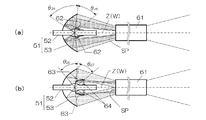
このため、図7(a)に示すように、高圧放電ランプ52の発光部54から凹面反射鏡53の前面開口部53a側へ放射される光を発光部54の中心(発光点)方向へ反射させる副反射鏡62もしくは反射膜(図示せず)を設けたものも提案されている(特許文献1、2、3及び4参照)。
これによれば、後方側に所定角度θ24で放射される光は凹面反射鏡53で反射されて集光エリアSPに届き、前方側に所定角度θ25で放射される光は副反射鏡62により反射されて、再び発光部54の中心(発光点)を通り背面側の反射鏡53で反射されて集光エリアSPに至る。したがって、前方に照射された光の漏洩が抑えられ、光の利用効率も高い。
According to this, the light radiated to the rear side at the predetermined angle θ 24 is reflected by the concave reflecting
しかし、副反射鏡62や反射膜は、発光部54から放射される光を発光部54へ反射させるため、その反射光により、発光部54内に配された電極が過熱され、その先端部からの電極物質の蒸発飛散量が多くなって発光部54の内表面に付着し、早期黒化を生ずるおそれがあると同時に、ランプ点灯時に最も高温となる電極先端部から放射される熱や、その部分から伝播される熱により発光部54の封止部55A側の内表面温度が著しく上昇して、発光部54の膨れや破裂を生ずるおそれがあった。
However, since the sub-reflecting mirror 62 and the reflecting film reflect the light emitted from the
また、図7(b)に示すように、高圧放電ランプ52の発光部54から凹面反射鏡53の前面開口部53a側へ放射される光を発光部54側へ反射させずに、前方へ直接反射させる補助反射鏡63を設けて、高圧放電ランプ51の光利用効率を高めることも可能である(特許文献5参照)。
この場合も、後方側に所定角度θ26で放射される光は凹面反射鏡53で反射されて集光エリアSPに達し、前方側に所定角度θ27で放射される光は補助反射鏡63により反射されて集光エリアSPに達する。したがって、前方に放射された光の漏洩が抑えられ、光の利用効率も高い。
Also in this case, the light radiated to the rear side at the predetermined angle θ 26 is reflected by the concave
しかし、補助反射鏡63に形成される反射膜は、一般に、誘電体薄膜を数十層以上積層させて形成されるので、その製造に手間と時間がかかり、製造コストが嵩むだけでなく、過熱により反射膜が劣化して剥離するなど耐久性に問題を生ずる。
さらに、このような補助反射鏡63は金属製のスポーク64により支持せざるを得ず、したがってランプ52を点灯させたときに、スポーク64の影が写り込んだり、過熱によりスポーク64が歪んで配光が崩れたり、酸化して錆びるなどの問題を生じていた。
However, the reflecting film formed on the auxiliary reflecting
Further, such an auxiliary reflecting
また、凹面反射鏡は正面から見て円形であることから、光軸方向から見て方形断面の収納スペースに装着するために、凹面反射鏡の先端フランジ部は正方形に形成するのが一般的である。
しかし、設計の都合上、照明光学系の収納スペースを長方形にせざるを得ない場合があり、この場合、反射鏡の有効面積は直径の3乗に比例するため、収納スペースを1辺5cmの正方形断面から、幅×縦=5×4cmの長方形とする場合に、反射鏡を5cmから4cmに20%減するだけで、有効反射面積は約64/125と、約50%まで低下してしまう。
In addition, since the concave reflecting mirror is circular when viewed from the front, the front flange portion of the concave reflecting mirror is generally formed in a square in order to be mounted in a storage space having a square cross section when viewed from the optical axis direction. is there.
However, there are cases where the storage space of the illumination optical system has to be rectangular for the sake of design. In this case, the effective area of the reflector is proportional to the cube of the diameter, so the storage space is a square with a side of 5 cm. From the cross-section, when the rectangle of width × length = 5 × 4 cm is used, the effective reflection area is reduced to about 50% by about 64/125 just by reducing the reflecting mirror by 20% from 5 cm to 4 cm.
このように、直径を小さくして反射鏡を小型化すると有効利用面積が激減するため、出願人は、光軸方向(正面)から見て円形の凹面反射鏡の直径をそのままに、上下を切り落として略長方形の形状の反射鏡を試作した。
この凹面反射鏡は、その光軸をZ軸とし、これに直交する二軸をX軸及びY軸としたときに、当該反射鏡の周面がZ軸を対称軸とし且つZX面に平行な二つの平面で切断したもので、反射鏡周面とY軸が交差する部分に二つのアーチ状の切欠部が対向形成され、水平断面で見たときは反射鏡の奥行きが深く、垂直断面で見たときは反射鏡が浅くなる。
これによれば、直径を小さくする場合に比して有効反射面積の低下が少なく光の利用効率の低下を抑えることができる。
ただし、アーチ状の切欠部が対向形成されることから、当然のことながら、切欠部がなければ、その部分で反射されて有効に利用できた光を利用することができなくなり、その分だけは、光の利用効率が低下するという問題を生ずる。
Thus, since the effective use area is drastically reduced if the diameter of the reflector is reduced by reducing the diameter, the applicant cuts off the top and bottom of the circular concave reflector as it is viewed from the optical axis direction (front). A prototype of a rectangular reflector was made.
In this concave reflecting mirror, when the optical axis is the Z-axis and the two axes orthogonal to the Z-axis are the X-axis and the Y-axis, the peripheral surface of the reflecting mirror is the Z-axis as the symmetry axis and parallel to the ZX plane. Cut by two planes, two arch-shaped cutouts are formed opposite each other at the intersection of the reflector's peripheral surface and the Y axis, and when viewed in a horizontal section, the depth of the reflector is deep and the section is vertical. When viewed, the reflector becomes shallow.
According to this, compared with the case where a diameter is made small, the fall of an effective reflective area is few, and the fall of the utilization efficiency of light can be suppressed.
However, since the arch-shaped cutouts are formed facing each other, of course, if there are no cutouts, it is impossible to use the light that has been reflected and effectively used by that part. This causes a problem that the light utilization efficiency is lowered.
そこで本発明は、光軸方向から見て円形の凹面反射鏡の上下を切り落として略長方形の形状としたときでも、副反射鏡や補助反射鏡を用いることなく、もとの円形凹面反射鏡を用いた場合と同程度まで光利用効率を向上させることを技術的課題としている。 In view of this, the present invention eliminates the need for using the original circular concave reflecting mirror without using a sub-reflecting mirror or an auxiliary reflecting mirror even when the upper and lower sides of the circular concave reflecting mirror as viewed from the optical axis direction are cut off to form a substantially rectangular shape. The technical problem is to improve the light utilization efficiency to the same extent as when it is used.
この課題を解決するために、本発明は、高圧放電ランプと、光軸を中心軸とする回転凹曲面状の反射面を有する凹面反射鏡とを備え、高圧放電ランプは、発光部を挟んで管軸方向前後両端に封止部が形成された発光管に、その両側封止部から電極アセンブリが挿通され、先端電極部を前記発光部内で対向させた状態で当該封止部が気密封止されると共に、その管軸を凹面反射鏡の光軸に一致させた状態に配され、前記発光部からその周囲に向かって前後方向に所定の角度範囲で放射される光の一部を前記凹面反射鏡で反射させてランプ前方に形成された所定の大きさの集光エリアに照射させるランプ装置において、前記凹面反射鏡は、その光軸をZ軸とし、これに直交する二軸をX軸及びY軸としたときに、当該反射鏡の周面がZ軸を対称軸とし且つZX面に平行な二つの平面で切断されて、反射鏡周面とY軸が交差する部分に二つのアーチ状の切欠部が対向形成され、前記発光部の外周面には、発光部から前記切欠部に向ってY軸方向に所定の角度範囲で照射される光束と交差する部分に反射プリズムが設けられ、当該反射プリズムには、その光をランプ前方に形成された前記集光エリアに向かって反射させるプリズム反射面がZX面に対して対称に形成されていることを特徴としている。 In order to solve this problem, the present invention includes a high-pressure discharge lamp and a concave reflector having a reflecting surface having a rotating concave curved surface with the optical axis as the central axis, and the high-pressure discharge lamp sandwiches the light emitting portion. An arc tube having sealing portions formed at both ends in the tube axis direction is inserted into the electrode assembly from both side sealing portions, and the sealing portion is hermetically sealed with the tip electrode portion facing the light emitting portion. And a portion of light emitted in a predetermined angular range in the front-rear direction from the light-emitting portion toward the periphery thereof is arranged in a state in which the tube axis coincides with the optical axis of the concave reflecting mirror. In the lamp device that reflects the light by a reflecting mirror and irradiates a condensing area of a predetermined size formed in front of the lamp, the concave reflecting mirror has an optical axis as a Z axis and two axes orthogonal to the X axis as an X axis. And the Y axis, the peripheral surface of the reflecting mirror is the axis of symmetry about the Z axis And two arch-shaped notches are formed opposite to each other at a portion where the reflecting mirror circumferential surface and the Y axis intersect with each other, and the light emitting portion is formed on the outer peripheral surface of the light emitting portion. A reflecting prism is provided at a portion intersecting with a light beam irradiated in a predetermined angle range in the Y-axis direction from the light source to the notch portion, and the light condensing area formed in front of the lamp in the reflecting prism. It is characterized in that the prism reflecting surface that reflects toward the surface is formed symmetrically with respect to the ZX plane.
本発明によれば、凹面反射鏡は、その光軸をZ軸とし、これに直交する二軸をX軸及びY軸としたときに、当該反射鏡の周面がZ軸を対称軸とし且つZX面に平行な二つの平面で切断されて、反射鏡周面とY軸が交差する部分に二つのアーチ状の切欠部が対向形成されているため、正面から見て上下が切り落とされた略長方形の形状をしている。
この場合、発光部から切欠部が形成されていない部分に向かって照射された光は、直接、反射鏡で反射され、ランプ前方に形成された所定の大きさの集光エリアに達し、その反射面積は直径を小さくした場合よりも大きいので、光学系の収納スペースを長方形断面にせざるを得ない場合であっても、比較的高い光の反射光率を確保することができる。
According to the present invention, when the concave reflecting mirror has the optical axis as the Z axis and the two axes perpendicular thereto as the X axis and the Y axis, the peripheral surface of the reflecting mirror has the Z axis as the symmetry axis, and It is cut by two planes parallel to the ZX plane, and two arch-shaped cutouts are formed facing each other at the intersection of the reflecting mirror circumferential surface and the Y axis. It has a rectangular shape.
In this case, the light emitted from the light emitting part toward the part where the notch part is not formed is directly reflected by the reflecting mirror, reaches a light collecting area of a predetermined size formed in front of the lamp, and the reflection Since the area is larger than when the diameter is reduced, a relatively high reflected light rate can be ensured even when the storage space of the optical system must be rectangular.
さらに、発光部の外周面には、発光部から反射鏡の切欠部に向ってY軸を中心に所定の角度範囲で照射される光束と交差する部分にプリズム反射面が形成されているので、発光部から切欠部に向かって照射された光はそのプリズム反射面で反射されて集光エリアに達する。
したがって、反射鏡に切欠部を形成しても、プリズムを設けたことにより切欠部に向かって照射された光が集光エリアに向かって反射されることとなるので、切欠部を形成したことによる光の利用効率の低下はほとんどなく、光学系の収納スペースを長方形断面に形成しなければならない場合であっても、その長軸を一辺の長さとする正方形断面の収納スペースを確保した場合と同じ光量を確保することができる。
Furthermore, a prism reflecting surface is formed on the outer peripheral surface of the light emitting portion at a portion intersecting with the light beam irradiated from the light emitting portion toward the cutout portion of the reflecting mirror in a predetermined angle range around the Y axis. light emitted toward the notch from the light emitting part is Isa anti at the prism reflective surface reach the light collection area.
Therefore, even when forming a notch in the reflector, the light emitted toward the notch by providing the prism is be Isa reaction toward the condenser area, to the formation of the notch There is almost no decline in the light utilization efficiency due to the fact that even when the storage space of the optical system has to be formed in a rectangular cross section, a storage space of a square cross section with the long axis as one side is secured. The same amount of light can be secured.
本例では、光軸方向から見て円形の凹面反射鏡の上下を切り落として略長方形の形状としたときであっても、副反射鏡や補助反射鏡を用いることなく、高圧放電ランプの光利用効率を向上するという目的を達成するために、高圧放電ランプと、光軸を中心軸とする回転凹曲面状の反射面を有する凹面反射鏡とを備えたランプ装置において、凹面反射鏡は、その光軸をZ軸とし、これに直交する二軸をX軸及びY軸としたときに、当該反射鏡の周面がZ軸を対称軸とし且つZX面に平行な二つの平面で切断されて、反射鏡周面とY軸が交差する部分に二つのアーチ状の切欠部が対向形成され、発光部の外周面には、発光部から前記切欠部に向ってY軸方向に所定の角度範囲で照射される光束と交差する部分に反射プリズムが設けられ、当該反射プリズムには、その光をランプ前方に形成された前記集光エリアに向かって反射させるプリズム反射面をZX面に対して対称に形成した。
In this example, even when the upper and lower sides of the circular concave reflecting mirror as viewed from the optical axis direction are cut off to form a substantially rectangular shape, the light of the high-pressure discharge lamp is used without using the sub-reflecting mirror or the auxiliary reflecting mirror. In order to achieve the purpose of improving the efficiency, in a lamp device including a high-pressure discharge lamp and a concave reflecting mirror having a rotating concave curved reflecting surface with the optical axis as a central axis, the concave reflecting mirror is When the optical axis is the Z axis and the two axes perpendicular to it are the X axis and the Y axis, the peripheral surface of the reflecting mirror is cut by two planes having the Z axis as the symmetry axis and parallel to the ZX plane. Two arch-shaped notches are formed to face each other at the intersection of the reflecting mirror circumferential surface and the Y axis, and the outer circumferential surface of the light emitting portion has a predetermined angular range in the Y axis direction from the light emitting portion toward the notched portion. Reflective prisms are provided at the intersections with the light beam irradiated at The rhythm was formed symmetrically prism reflecting surface for reflecting towards the light into the focusing area formed in the lamp forward with respect to the ZX plane.
以下、本発明を図面に示す実施例に基づいて説明する。
図1(a)及び(b)は本発明に係るランプ装置の正面図及び垂直−水平断面図、図2はその全体外観図、図3はプリズムの製造工程を示す説明図である。
Hereinafter, the present invention will be described based on embodiments shown in the drawings.
1A and 1B are a front view and a vertical-horizontal sectional view of a lamp device according to the present invention, FIG. 2 is an overall external view thereof, and FIG. 3 is an explanatory view showing a prism manufacturing process.
図1は本発明に係るランプ装置の一例を示し、このランプ装置1は、高圧放電ランプ2とその光を反射する楕円面鏡又は放物面鏡などの回転凹曲面状の反射面を有する凹面反射鏡3とを備えている。
そして、例えば、液晶プロジェクタの光源として使用され、ロッドレンズやアレイレンズなどの光量分布均一化光学系(ホモジナイザー)11を透過した光が、画像生成部となる液晶パネル(図示せず)に照射されるように配されている。
FIG. 1 shows an example of a lamp device according to the present invention. The lamp device 1 has a concave surface having a high-voltage discharge lamp 2 and a rotating concave curved reflecting surface such as an elliptical mirror or a parabolic mirror for reflecting the light. And a reflecting
Then, for example, light used as a light source of a liquid crystal projector and transmitted through a light quantity uniformizing optical system (homogenizer) 11 such as a rod lens or an array lens is irradiated to a liquid crystal panel (not shown) serving as an image generation unit. It is arranged so that.
高圧放電ランプ2は、発光部4を挟んで管軸方向前後両端に封止部5A、5Bが形成された発光管6に、その両側封止部5A,5Bから一対の電極アセンブリ7が挿通されている。
電極アセンブリ7は、タングステンでなる先端電極部8とモリブデン箔9とモリブデン線10とを直列的に溶接して形成され、その先端電極部8が前記発光部4内に対向された状態で封止部5A、5Bが気密封止されている。
In the high pressure discharge lamp 2, a pair of
The
高圧放電ランプ2と凹面反射鏡3は、ランプ2の一方の封止部5Aが反射鏡3の開口部3a側に向けられ、他方の封止部5Bが反射鏡3のボトム3b側に向けられて、ランプ2の管軸Wと反射鏡3の光軸Zが同軸的に位置するように固定されている。
これにより、発光部4からその周囲に向かって前後方向に所定の角度範囲で放射される光の一部(主として後方に向かう光)を凹面反射鏡3で反射させ、ランプ前方に配されたロッドレンズなど光量分布均一化光学系11の光入射面など所定の大きさの集光エリアSPに集光照射させるようになっている。
In the high pressure discharge lamp 2 and the concave reflecting
As a result, a part of the light emitted from the
また、凹面反射鏡3は、光軸Zに直交する二軸をX軸及びY軸としたときに、当該反射鏡3の周面が光軸Zを対称軸とし且つZX面に平行な二つの平面で切断されて、反射鏡周面とY軸が交差する部分に二つのアーチ状の切欠部12A、12Bが対向形成されている。
The concave reflecting
そして、発光管6の発光部4の外周面には、発光部4から切欠部12A及び12Bに向ってY軸方向に所定の角度範囲(前後θy、左右δy)で照射される光束と交差する部分に、反射プリズム14が設けられ、当該反射プリズム14には、その光を前記集光エリアSPに向かって反射させる二つのプリズム反射面13A、13Bが、ZX面に対して対称に形成されている。
本例では、プリズム反射面13A、13Bを有する反射プリズム14にリング状の装着部15が形成されており、プリズム反射面13A,13Bが発光部4の外周面に位置するように発光管6の封止部5Aに外装され、隙間に充填されたフリットガラス24を溶融させることにより固定している。
The outer peripheral surface of the
In this embodiment, the prism
この反射プリズム14は、プリズム面を環状に形成した後、その左右両側を装着部15の外径に等しい間隔の平行面で切断することにより形成されている。
より具体的には、図1(a)で示す正面図において、発光部4の発光点P0を中心に切欠部12A及び12Bに対応するXY1−XY2及びXY3−XY4に向かってα1の角度範囲で照射される光束と交差する部分にプリズム反射面13A、13Bが形成され、発光部4から照射された光を集光エリアSPに向かって反射させるようになっている。また、発光部4の発光点P0を中心に切欠部12A及び12Bが形成されていない部分XY2−XY3及びXY4−XY1に向かってα2の角度範囲で照射される光束は、反射プリズム14に入射されることなく反射鏡3で直接反射されるようになっている。
また、図1(b)の中心線上方に示す垂直断面図において、発光部4の発光点P0を中心に有効反射面ZY1−ZY2に向かってβ1の角度範囲で照射される光は凹面反射鏡3で直接反射されるように、その光路中には反射プリズム14が配置されていない。また、発光点P0を中心に切欠部12A及び12Bに対応するZY2−ZY3に向かってβ2の角度範囲で照射される光束と交差する部分には反射プリズム14が配され、そのプリズム反射面13A、13Bが形成され、発光部4から照射された光を集光エリアSPに向かって反射させるようになっている。
さらに、図1(b)の中心線下方に示す水平断面図において、発光部4の発光点P0を中心に有効反射面ZX1−ZX2に向かってγの角度範囲で照射される光束と交差する部分に反射プリズム14はなく、その光は全て反射鏡3で反射され、集光エリアSPに達する。
The reflecting
More specifically, in the front view shown in FIG. 1 (a), towards the XY 1 -XY 2 and XY 3 -XY 4 corresponding to the
Further, in the vertical cross-sectional view shown above the center line of FIG. 1B, the light irradiated in the angle range of β 1 toward the effective reflection surface ZY 1 -ZY 2 around the light emitting point P 0 of the
Furthermore, in the horizontal cross-sectional view shown below the center line in FIG. 1B, the luminous flux irradiated in the angle range of γ toward the effective reflection surface ZX 1 -ZX 2 around the light emitting point P 0 of the
これにより、発光部4から切欠部12A,12Bに向かう光も、プリズム反射面13A,13Bで反射されて集光エリアSPに達するので、切欠部12A,12Bを形成していない同径の反射鏡の光利用効率と略同一の効率で光を利用することができる。
Thus, the
図3は反射プリズム14の製造工程を示す。
プリズム14は石英微粒子21を型22に入れ、加圧して焼結用成形体16を形成し、型バラシして取り出した後に、これを焼結して環状プリズム18を形成する。
型22は、図3(a)に示すように、左右に分割された外枠23R、23Lと、プリズム14の孔を形成する中子を兼用するベース23Bと、前記外枠23R、23L及びベース23Bで形成されるキャビティに充填された石英微粒子21を加圧する二重円筒状の加圧子23P、23Qからなる。
FIG. 3 shows a manufacturing process of the reflecting
The
As shown in FIG. 3A, the
まず、図3(b)に示すように、前記外枠23R、23L及びベース23Bを組み立てることにより形成されるキャビティに石英微粒子21を充填し、図3(c)に示すように外側の加圧子23Pで加圧したところで、さらに、石英微粒子21を充填する。
次いで、図3(d)に示すように内側の加圧子23Qで加圧して、焼結用成形体16を形成した後、型バラシして焼結用成形体16を取り出し焼結すると、図3(e)に示すようにリング状の装着部15の周囲に環状のプリズム面17が形成された環状プリズム18が完成する。
First, as shown in FIG. 3 (b), a cavity formed by assembling the
Next, as shown in FIG. 3D, pressurization is performed with the
そして、環状プリズム18の周面をZY面に平行で、装着部15の外径に等しい間隔の平行面で切断すると、図3(f)に示すように、ZX面に対して上下に対称な二つのプリズム反射面13A、13Bが形成され、その全面を光学研磨することにより、反射プリズム14が完成する。
なお、環状プリズム18を切断する平行面の間隔は、反射鏡3に形成された切欠部12A、12Bの大きさに応じて決定される。
すなわち、図1(a)で見て、切欠部12A及び12Bに対応するXY1−XY2及びXY3−XY4に向かってα1の角度範囲で照射される光束と交差する部分にプリズム反射面13A、13Bが形成されるように、平行面の間隔を選定する。
Then, when the circumferential surface of the
The interval between the parallel surfaces that cut the
That is, as shown in FIG. 1A, the prism is reflected at a portion intersecting with the light beam irradiated in the angle range of α 1 toward XY 1 -XY 2 and XY 3 -XY 4 corresponding to the
そして、このように形成された反射プリズム14の装着部15を発光管6の封止部5Aに外装し、隙間にフリットガラス24を充填してこれを溶融させて固着させ、この発光管6を凹面反射鏡3に装着したランプ装置1により光を照射すると、正面から見てX軸方向に角度α2、水平断面で見て角度γで出射された光は、反射鏡3で反射されて集光エリアSPに達する。この光束の反射効率は、切欠部12A、12Bが形成されていない場合の同径の反射鏡における反射効率に等しい。
Then, the mounting
また、正面から見てY軸方向に角度α1、垂直断面で見て角度β1+β2で出射された光は、反射鏡3に切欠部12A、12Bが形成されていなければ、すべて反射鏡3で反射されて集光エリアSPに達するが、切欠部12A、12Bが対向形成されているため、反射面ZY1−ZY2に向かってβ1の角度範囲で照射される光のみが反射鏡3で反射されて集光エリアSPに達する。
また、切欠部12A及び12Bに対応するZY2−ZY3に向かってβ2の角度範囲で出射された光は、この光束と交差する部分に配されたプリズム14に入射されてプリズム反射面13A,13Bで反射され、集光エリアSPに達する。
したがって、切欠部12A及び12Bを形成したことにより反射鏡3で反射されない光も、プリズム14で反射されて集光エリアにSPに達するので、この光束の反射効率は、切欠部12A、12Bが形成されていない場合の同径の反射鏡における反射効率に等しい。
In addition, light emitted at an angle α 1 in the Y-axis direction as viewed from the front and an angle β 1 + β 2 as viewed in the vertical section is all a reflecting mirror unless the
Further, the light emitted by the beta 2 angular range toward the ZY 2 -ZY 3 corresponding to the
Therefore, even light that is not reflected by the reflecting
すなわち、本発明では、反射鏡3を断面長方形の収納スペースに収めるために、反射鏡3の周面をZX面に平行な二つの平面で切断することにより正面から見て長方形の形状とすることによって、反射鏡周面とY軸が交差する部分(上下両側)に二つのアーチ状の切欠部12A、12Bを対向形成することとなっても、その切欠部12A、12Bがなければ反射鏡3で反射して集光エリアSPに達する筈であった光が、プリズム14に入射されてプリズム反射面13A,13Bで反射され、集光エリアSPに達するので、切欠部12A,12Bが形成されていない同径の反射鏡と同等の光利用効率を得ることができる。
That is, in the present invention, in order to store the reflecting
以上述べたように、本発明は、特に、液晶プロジェクタやDLPプロジェクタ等の光源等の用途に適用できる。 As described above, the present invention is particularly applicable to uses such as light sources such as liquid crystal projectors and DLP projectors.
1
ランプ装置
2
高圧放電ランプ
3
凹面反射鏡
4
発光部
5A
封止部
5B
封止部
6
発光管
7
電極アセンブリ
SP
集光エリア
12A
切欠部
12B
切欠部
13A
プリズム反射面
13B
プリズム反射面
14
反射プリズム
1
Lamp device 2
High
Sealing
Sealing part 6
Electrode assembly SP
Condensing
Reflective prism
Claims (2)
高圧放電ランプは、発光部を挟んで管軸方向前後両端に封止部が形成された発光管に、その両側封止部から電極アセンブリが挿通され、先端電極部を前記発光部内で対向させた状態で当該封止部が気密封止されると共に、その管軸を凹面反射鏡の光軸に一致させた状態に配され、
前記発光部からその周囲に向かって前後方向に所定の角度範囲で放射される光の一部を前記凹面反射鏡で反射させてランプ前方に形成された所定の大きさの集光エリアに照射させるランプ装置において、
前記凹面反射鏡は、その光軸をZ軸とし、これに直交する二軸をX軸及びY軸としたときに、当該反射鏡の周面がZ軸を対称軸とし且つZX面に平行な二つの平面で切断されて、反射鏡周面とY軸が交差する部分に二つのアーチ状の切欠部が対向形成され、
前記発光部の外周面には、発光部から前記切欠部に向ってY軸方向に所定の角度範囲で照射される光束と交差する部分に反射プリズムが設けられ、
当該反射プリズムには、その光をランプ前方に形成された前記集光エリアに向かって反射させるプリズム反射面がZX面に対して対称に形成されていることを特徴とするランプ装置。 A high-pressure discharge lamp and a concave reflecting mirror having a rotating concave curved reflecting surface with the optical axis as the central axis,
In the high pressure discharge lamp, an electrode assembly is inserted from both side sealing portions into a light emitting tube in which sealing portions are formed at both front and rear ends in the tube axis direction across the light emitting portion, and the tip electrode portion is opposed to the inside of the light emitting portion. The sealing part is hermetically sealed in a state, and the tube axis is arranged in a state of matching the optical axis of the concave reflecting mirror,
A part of light emitted from the light emitting portion toward the periphery in a predetermined angle range in the front-rear direction is reflected by the concave reflecting mirror to irradiate a condensing area of a predetermined size formed in front of the lamp. In the lamp device,
The concave reflecting mirror has a Z axis as its optical axis and an X axis and a Y axis as two axes orthogonal to the Z axis, and the peripheral surface of the reflecting mirror has the Z axis as a symmetry axis and is parallel to the ZX plane. Cut by two planes, two arch-shaped notches are formed facing each other at the intersection of the reflecting mirror circumferential surface and the Y axis,
On the outer peripheral surface of the light emitting unit, a reflecting prism is provided at a portion that intersects the light beam irradiated from the light emitting unit toward the notch in a predetermined angle range in the Y-axis direction,
The lamp device according to claim 1 , wherein a prism reflecting surface for reflecting the light toward the condensing area formed in front of the lamp is formed symmetrically with respect to the ZX plane.
Priority Applications (6)
| Application Number | Priority Date | Filing Date | Title |
|---|---|---|---|
| JP2008297196A JP5373373B2 (en) | 2008-11-20 | 2008-11-20 | Lamp device |
| CA2743550A CA2743550A1 (en) | 2008-11-20 | 2008-12-03 | Lamp device |
| CN2008801320476A CN102224563B (en) | 2008-11-20 | 2008-12-03 | Lamp device |
| US13/130,121 US8476814B2 (en) | 2008-11-20 | 2008-12-03 | Lamp device |
| PCT/JP2008/071924 WO2010058489A1 (en) | 2008-11-20 | 2008-12-03 | Lamp device |
| EP08878285A EP2352162A4 (en) | 2008-11-20 | 2008-12-03 | Lamp device |
Applications Claiming Priority (1)
| Application Number | Priority Date | Filing Date | Title |
|---|---|---|---|
| JP2008297196A JP5373373B2 (en) | 2008-11-20 | 2008-11-20 | Lamp device |
Publications (2)
| Publication Number | Publication Date |
|---|---|
| JP2010122532A JP2010122532A (en) | 2010-06-03 |
| JP5373373B2 true JP5373373B2 (en) | 2013-12-18 |
Family
ID=42197935
Family Applications (1)
| Application Number | Title | Priority Date | Filing Date |
|---|---|---|---|
| JP2008297196A Expired - Fee Related JP5373373B2 (en) | 2008-11-20 | 2008-11-20 | Lamp device |
Country Status (6)
| Country | Link |
|---|---|
| US (1) | US8476814B2 (en) |
| EP (1) | EP2352162A4 (en) |
| JP (1) | JP5373373B2 (en) |
| CN (1) | CN102224563B (en) |
| CA (1) | CA2743550A1 (en) |
| WO (1) | WO2010058489A1 (en) |
Families Citing this family (4)
| Publication number | Priority date | Publication date | Assignee | Title |
|---|---|---|---|---|
| DE102010050343A1 (en) * | 2010-11-05 | 2012-05-10 | Heraeus Materials Technology Gmbh & Co. Kg | Chip-integrated via contacting of multi-layer substrates |
| RU2672051C2 (en) * | 2014-01-03 | 2018-11-09 | Филипс Лайтинг Холдинг Б.В. | Optical element, lighting device and luminaire |
| KR101683969B1 (en) * | 2014-07-01 | 2016-12-08 | 현대자동차주식회사 | Lighting apparatus for vehicle |
| US10950743B2 (en) * | 2019-05-02 | 2021-03-16 | Stmicroelectronics (Research & Development) Limited | Time of flight (TOF) sensor with transmit optic providing for reduced parallax effect |
Family Cites Families (15)
| Publication number | Priority date | Publication date | Assignee | Title |
|---|---|---|---|---|
| JPH0646687B2 (en) | 1989-12-13 | 1994-06-15 | 松下電器産業株式会社 | Mixer |
| JP3204733B2 (en) | 1992-05-15 | 2001-09-04 | 松下電器産業株式会社 | Lighting equipment |
| JP3204739B2 (en) | 1992-06-30 | 2001-09-04 | ナカ工業株式会社 | Panel support members |
| JPH0815002B2 (en) * | 1993-02-26 | 1996-02-14 | スタンレー電気株式会社 | Fog lights |
| JP3184404B2 (en) | 1994-07-13 | 2001-07-09 | 松下電子工業株式会社 | Metal halide lamp with reflector |
| JP2001125197A (en) | 1999-10-27 | 2001-05-11 | Matsushita Electric Ind Co Ltd | Light source device, illuminator and projection type display device |
| DE10151267A1 (en) | 2001-10-17 | 2003-04-30 | Philips Corp Intellectual Pty | lighting unit |
| JP2004093653A (en) * | 2002-08-29 | 2004-03-25 | Seiko Epson Corp | Light source for projector, and projector |
| JP2005070429A (en) * | 2003-08-25 | 2005-03-17 | Seiko Epson Corp | Light source device and projector equipped therewith |
| JP4193063B2 (en) | 2004-03-22 | 2008-12-10 | セイコーエプソン株式会社 | Lamp device and projector equipped with the same |
| JP2005309373A (en) | 2004-03-25 | 2005-11-04 | Fuji Photo Film Co Ltd | Image forming method using heat developable photosensitive material |
| JP2006294268A (en) * | 2005-04-05 | 2006-10-26 | Matsushita Electric Ind Co Ltd | Lamp unit |
| JP4873217B2 (en) * | 2005-04-08 | 2012-02-08 | カシオ計算機株式会社 | Light source device and projector |
| JP2007073276A (en) * | 2005-09-06 | 2007-03-22 | Matsushita Electric Ind Co Ltd | Lamp unit |
| JP4797931B2 (en) * | 2006-10-30 | 2011-10-19 | 岩崎電気株式会社 | High pressure discharge lamp and lamp with reflector using the same |
-
2008
- 2008-11-20 JP JP2008297196A patent/JP5373373B2/en not_active Expired - Fee Related
- 2008-12-03 EP EP08878285A patent/EP2352162A4/en not_active Withdrawn
- 2008-12-03 US US13/130,121 patent/US8476814B2/en not_active Expired - Fee Related
- 2008-12-03 WO PCT/JP2008/071924 patent/WO2010058489A1/en active Application Filing
- 2008-12-03 CA CA2743550A patent/CA2743550A1/en not_active Abandoned
- 2008-12-03 CN CN2008801320476A patent/CN102224563B/en not_active Expired - Fee Related
Also Published As
| Publication number | Publication date |
|---|---|
| CA2743550A1 (en) | 2010-05-27 |
| US8476814B2 (en) | 2013-07-02 |
| CN102224563A (en) | 2011-10-19 |
| US20110260600A1 (en) | 2011-10-27 |
| EP2352162A4 (en) | 2012-05-30 |
| EP2352162A1 (en) | 2011-08-03 |
| JP2010122532A (en) | 2010-06-03 |
| WO2010058489A1 (en) | 2010-05-27 |
| CN102224563B (en) | 2013-12-25 |
Similar Documents
| Publication | Publication Date | Title |
|---|---|---|
| US7213944B2 (en) | Light source apparatus, lighting apparatus and projection display apparatus | |
| US8308307B2 (en) | Illuminator and projector | |
| JP5373373B2 (en) | Lamp device | |
| US6734628B2 (en) | Discharge lamp, lamp unit and image display apparatus | |
| US20070279916A1 (en) | Light source device | |
| JP3633490B2 (en) | Light source device and projector using the same | |
| JP2008234897A (en) | Light source device and projector | |
| JP4736961B2 (en) | Light source device | |
| JP5034755B2 (en) | Arc tube, light source device and projector | |
| JP2005005183A (en) | High-pressure mercury lamp, light source device, and projector | |
| JP4525803B2 (en) | Arc tube, light source device and projector | |
| JP2009037989A (en) | Lamp fixture | |
| JPH11327047A (en) | Projecting device | |
| JP2006092910A (en) | Reflecting mirror integration type lamp | |
| JP5403173B2 (en) | Arc tube, light source device and projector | |
| JP3641975B2 (en) | Light source device and projection display device | |
| JP2006120358A (en) | Light source device and projector | |
| JP2008243640A (en) | Light source device, projector, and light source lamp | |
| JP2010003542A (en) | Reflector, light source device, and projector | |
| JP2011040183A (en) | Light source device and projector | |
| JP2008242156A (en) | Light source device and projector | |
| JP2012089356A (en) | Light source device and projector | |
| JP2009043451A (en) | Arc tube, light source device, and projector | |
| JP2010177035A (en) | Light-emitting device | |
| JP2008242158A (en) | Light source device and projector |
Legal Events
| Date | Code | Title | Description |
|---|---|---|---|
| A621 | Written request for application examination |
Free format text: JAPANESE INTERMEDIATE CODE: A621 Effective date: 20111116 |
|
| A131 | Notification of reasons for refusal |
Free format text: JAPANESE INTERMEDIATE CODE: A131 Effective date: 20121211 |
|
| A521 | Request for written amendment filed |
Free format text: JAPANESE INTERMEDIATE CODE: A523 Effective date: 20130212 |
|
| A131 | Notification of reasons for refusal |
Free format text: JAPANESE INTERMEDIATE CODE: A131 Effective date: 20130305 |
|
| A521 | Request for written amendment filed |
Free format text: JAPANESE INTERMEDIATE CODE: A523 Effective date: 20130422 |
|
| TRDD | Decision of grant or rejection written | ||
| A01 | Written decision to grant a patent or to grant a registration (utility model) |
Free format text: JAPANESE INTERMEDIATE CODE: A01 Effective date: 20130910 |
|
| A61 | First payment of annual fees (during grant procedure) |
Free format text: JAPANESE INTERMEDIATE CODE: A61 Effective date: 20130919 |
|
| R150 | Certificate of patent or registration of utility model |
Free format text: JAPANESE INTERMEDIATE CODE: R150 |
|
| LAPS | Cancellation because of no payment of annual fees |