US7213944B2 - Light source apparatus, lighting apparatus and projection display apparatus - Google Patents
Light source apparatus, lighting apparatus and projection display apparatus Download PDFInfo
- Publication number
- US7213944B2 US7213944B2 US10/553,489 US55348905A US7213944B2 US 7213944 B2 US7213944 B2 US 7213944B2 US 55348905 A US55348905 A US 55348905A US 7213944 B2 US7213944 B2 US 7213944B2
- Authority
- US
- United States
- Prior art keywords
- light
- concave mirror
- mirror
- light source
- source apparatus
- Prior art date
- Legal status (The legal status is an assumption and is not a legal conclusion. Google has not performed a legal analysis and makes no representation as to the accuracy of the status listed.)
- Expired - Lifetime
Links
- 238000004020 luminiscence type Methods 0.000 claims abstract description 33
- 230000004907 flux Effects 0.000 claims description 49
- 230000005855 radiation Effects 0.000 claims description 20
- RWYFURDDADFSHT-RBBHPAOJSA-N diane Chemical compound OC1=CC=C2[C@H]3CC[C@](C)([C@](CC4)(O)C#C)[C@@H]4[C@@H]3CCC2=C1.C1=C(Cl)C2=CC(=O)[C@@H]3CC3[C@]2(C)[C@@H]2[C@@H]1[C@@H]1CC[C@@](C(C)=O)(OC(=O)C)[C@@]1(C)CC2 RWYFURDDADFSHT-RBBHPAOJSA-N 0.000 claims 1
- 230000003287 optical effect Effects 0.000 abstract description 89
- 230000005540 biological transmission Effects 0.000 abstract description 25
- 239000011521 glass Substances 0.000 description 6
- 238000005286 illumination Methods 0.000 description 5
- 230000002452 interceptive effect Effects 0.000 description 4
- 239000000463 material Substances 0.000 description 4
- 238000009877 rendering Methods 0.000 description 4
- 230000009471 action Effects 0.000 description 3
- 230000008901 benefit Effects 0.000 description 3
- 230000000694 effects Effects 0.000 description 3
- QSHDDOUJBYECFT-UHFFFAOYSA-N mercury Chemical compound [Hg] QSHDDOUJBYECFT-UHFFFAOYSA-N 0.000 description 3
- 229910052753 mercury Inorganic materials 0.000 description 3
- 229910001507 metal halide Inorganic materials 0.000 description 3
- 150000005309 metal halides Chemical class 0.000 description 3
- 238000000149 argon plasma sintering Methods 0.000 description 2
- 230000000903 blocking effect Effects 0.000 description 2
- 239000002131 composite material Substances 0.000 description 2
- 230000007423 decrease Effects 0.000 description 2
- 238000003384 imaging method Methods 0.000 description 2
- 230000006872 improvement Effects 0.000 description 2
- 230000031700 light absorption Effects 0.000 description 2
- 238000000034 method Methods 0.000 description 2
- 239000000203 mixture Substances 0.000 description 2
- 238000000926 separation method Methods 0.000 description 2
- 238000010586 diagram Methods 0.000 description 1
- 229910052736 halogen Inorganic materials 0.000 description 1
- 150000002367 halogens Chemical class 0.000 description 1
- 239000004973 liquid crystal related substance Substances 0.000 description 1
- 230000009467 reduction Effects 0.000 description 1
- 229910052724 xenon Inorganic materials 0.000 description 1
- FHNFHKCVQCLJFQ-UHFFFAOYSA-N xenon atom Chemical compound [Xe] FHNFHKCVQCLJFQ-UHFFFAOYSA-N 0.000 description 1
Images


Classifications
-
- F—MECHANICAL ENGINEERING; LIGHTING; HEATING; WEAPONS; BLASTING
- F21—LIGHTING
- F21V—FUNCTIONAL FEATURES OR DETAILS OF LIGHTING DEVICES OR SYSTEMS THEREOF; STRUCTURAL COMBINATIONS OF LIGHTING DEVICES WITH OTHER ARTICLES, NOT OTHERWISE PROVIDED FOR
- F21V7/00—Reflectors for light sources
- F21V7/0025—Combination of two or more reflectors for a single light source
-
- F—MECHANICAL ENGINEERING; LIGHTING; HEATING; WEAPONS; BLASTING
- F21—LIGHTING
- F21V—FUNCTIONAL FEATURES OR DETAILS OF LIGHTING DEVICES OR SYSTEMS THEREOF; STRUCTURAL COMBINATIONS OF LIGHTING DEVICES WITH OTHER ARTICLES, NOT OTHERWISE PROVIDED FOR
- F21V7/00—Reflectors for light sources
- F21V7/04—Optical design
- F21V7/09—Optical design with a combination of different curvatures
-
- G—PHYSICS
- G03—PHOTOGRAPHY; CINEMATOGRAPHY; ANALOGOUS TECHNIQUES USING WAVES OTHER THAN OPTICAL WAVES; ELECTROGRAPHY; HOLOGRAPHY
- G03B—APPARATUS OR ARRANGEMENTS FOR TAKING PHOTOGRAPHS OR FOR PROJECTING OR VIEWING THEM; APPARATUS OR ARRANGEMENTS EMPLOYING ANALOGOUS TECHNIQUES USING WAVES OTHER THAN OPTICAL WAVES; ACCESSORIES THEREFOR
- G03B21/00—Projectors or projection-type viewers; Accessories therefor
- G03B21/14—Details
- G03B21/20—Lamp housings
- G03B21/2006—Lamp housings characterised by the light source
- G03B21/2013—Plural light sources
-
- G—PHYSICS
- G03—PHOTOGRAPHY; CINEMATOGRAPHY; ANALOGOUS TECHNIQUES USING WAVES OTHER THAN OPTICAL WAVES; ELECTROGRAPHY; HOLOGRAPHY
- G03B—APPARATUS OR ARRANGEMENTS FOR TAKING PHOTOGRAPHS OR FOR PROJECTING OR VIEWING THEM; APPARATUS OR ARRANGEMENTS EMPLOYING ANALOGOUS TECHNIQUES USING WAVES OTHER THAN OPTICAL WAVES; ACCESSORIES THEREFOR
- G03B21/00—Projectors or projection-type viewers; Accessories therefor
- G03B21/14—Details
- G03B21/20—Lamp housings
- G03B21/2006—Lamp housings characterised by the light source
- G03B21/2026—Gas discharge type light sources, e.g. arcs
Definitions
- the present invention relates to a light source apparatus having light generating means and a concave mirror, a lighting apparatus and a projection display apparatus.
- FIG. 11 shows a conventional multi-lamp optical system having two light source apparatuses configured by the lamp and concave mirror provided therein.
- the light radiated from a light source apparatus 1 gets incident on a hollow rod integrator 2 made of glass poles or mirrors glued together. It repeats total reflection inside the glass in the case of the glass poles, or repeats reflection in the case of the type having the mirrors glued together. It is possible, by means of the reflection inside the rod integrator 2 , to create the luminous fluxes of homogeneous in-plane brightness on an emission opening plane of the rod integrator 2 .
- a relay lens 3 after this, to focus the luminous fluxes of high in-plane homogeneousness on a light modulation device 4 of performing an image display so as to display the image provided on a screen by a projection lens as the image of which in-screen brightness is highly homogeneous.
- FIG. 12 a basic configuration of the light source apparatus as a first conventional example is shown in FIG. 12 (refer to Japanese Patent No. 2543260 and Japanese Patent No. 3151734 for instance).
- the light radiated from light-transmitting planes 5 a and 5 b of a light-emitting portion 5 of the lamp is collected on a focus X by a first concave mirror 6 having an ellipsoidal or paraboloidal reflection plane form.
- the radiation light from the light-transmitting planes 5 a and 5 b of the light-emitting portion 5 of the lamp not collected by the first concave mirror 6 is reflected on a second concave mirror 7 consisting of a spherical mirror for instance and having its reflection plane facing the reflection plane of the first concave mirror 6 , and is then returned to the vicinity of the light-emitting portion 5 of the lamp so as to be collected on the focus X by the first concave mirror 6 .
- the first concave mirror 6 and the second concave mirror 7 are used in a state of having their reflection planes facing each other, the second concave mirror 7 having the outermost diameter larger than the outermost diameter in a vertical direction to an optical axis of the first concave mirror 6 , that is, a straight line connecting a luminescence center 5 c of the light-emitting portion 5 to the focus X.
- the light radiated from the light-emitting portion 5 of the lamp is thereby taken in as much as possible so as to be collected by the first concave mirror 6 .
- FIG. 15 The basic configuration of the light source apparatus as a second conventional example is shown in FIG. 15 (refer to Japanese Patent No. 2730782 and Japanese Patent No. 3350003 for instance).
- a light source 10 of the lamp is placed on a focus Y of an ellipsoidal mirror or paraboloidal reflecting mirror as a first concave mirror 8 .
- the first concave mirror 8 is provided at an angle capable of reflecting all the radiation light from a light-transmitting plane 10 a of the light source 10 .
- This light source apparatus coincides with the first conventional example in that the light radiated from the light-transmitting planes 10 a of the light source 10 and reflected on the spherical mirror as a second concave mirror 9 is returned to the vicinity of the focus of the first concave mirror 8 and as much light radiated from a light-transmitting portion 10 as possible is thus taken in together with the light radiated from the light-transmitting plane 10 b and directly collected by the first concave mirror 8 .
- the first conventional example has the opening of the second concave mirror 7 in a vertical plane against an optical axis direction of the first concave mirror 6 whereas the second conventional example has the second concave mirror 9 placed in a horizontal direction against the direction of the optical axis of the first concave mirror 8 , that is, the straight line connecting a luminescence center 10 c of the light-emitting portion 10 of the lamp to the focus Y.
- the conventional multi-lamp optical system has the configuration in which the light radiated from multiple light source apparatuses gets incident on the rod integrator 2 which is homogeneous lighting means.
- a transmissive/reflective liquid crystal of displaying the image and the light modulation device called a DMD (Digital Micro-mirror Device) have a luminous flux incident angle range capable of substantially modulating the light and an image display effective area capable of displaying the image.
- Helmholtz-Lagrange which is a basic formula of imaging optics
- an output angle range of the light according to the size of an outgoing side opening 2 b of the rod integrator 2 in an imaging relation with the relay lens 3 is uniquely decided by the relay lens 3 .
- the output angle range is equal to the incident angle range. If the outgoing side opening and the incident side opening are of different sizes, the incident angle range is in accordance with the size of the incident side opening induced by the relation of Helmholtz-Lagrange, and so only the luminous flux within this angle range is projected onto the screen via the rod integrator 2 , relay lens 3 , light modulation device 4 and projection lens.
- the incident angle range of the rod integrator 2 is limited. Therefore, there is a problem that a distance between the concave mirror 1 and an incident side opening 2 a of the rod integrator 2 becomes long and an optical spot size formed by the concave mirror 1 becomes large so that an amount of light to be taken in by the opening of the rod integrator 2 decreases.
- the light source apparatus of the first conventional example shown in FIG. 12 is in a form of rotation symmetry to the optical axis of the first concave mirror, that is, the straight line connecting the luminescence center 5 c of the light-emitting portion 5 of the lamp to the focus X. It has a problem that, in the case of forming a similar multi-lamp optical system, the amount of light to be taken in by the opening of the rod integrator 2 decreases. It also has a problem that its outer shape becomes large.
- the light source apparatus of the second conventional example shown in FIG. 15 is in a form of non-rotation asymmetry to the optical axis of the first concave mirror, that is, the straight line connecting the luminescence center 10 c of the light-emitting portion 10 of the lamp to the focus Y. Its outer shape can be smaller than that of the first conventional example.
- the luminous fluxes formed by collection of light can also be of non-rotation symmetry, and it is possible, even in the multi-lamp optical system of FIG. 11 , to reduce the distance between the first concave mirror 8 corresponding to the first concave mirror 6 and the incident side opening 2 a of the rod integrator 2 .
- the light source apparatus of the second conventional example shown in FIG. 15 has the following problem.
- the reflection plane having the second concave mirror 9 formed thereon reflects all the light radiated from the light-transmitting plane 10 a as shown in FIG. 15 . Nevertheless, all the reflected light is not collected by the first concave mirror 8 , but a part of it is radiated outside so as to become an impediment to light collection efficiency.
- the light radiated from a lamp 5 and directly reaching the first concave mirror 6 in an upper half in the light source apparatus of the first conventional example of FIG. 12 is taken in by the second concave mirror 9 in the light source apparatus of the second conventional example of FIG. 15 .
- the light reflected on the second concave mirror 9 passes through the vicinity of the light-emitting portion 10 of the lamp again so as to get to the first concave mirror 8 .
- a metal halide lamp or a mercury lamp as the lamp, much of the light passing through the light-emitting portion again is lost due to light absorption and light scattering of light-emitting materials and materials configuring the lamp.
- the present invention was made in order to solve these problems of the conventional examples, and an object thereof is to provide the light source apparatus of which optical usable efficiency is not lowered by miniaturizing it and the lighting apparatus and projection display apparatus of higher efficiency and capable of miniaturization by having the light source apparatus.
- the 1 st aspect of the present invention is a light source apparatus comprising:
- a reflection plane of the first concave mirror and a reflection plane of the second concave mirror are in a form of rotational asymmetry to a reference axis connecting a source of luminescence of the light generating means to a focus of the light collected by the first concave mirror respectively;
- a distance between the reflection plane of the second concave mirror and the source of luminescence is shorter than the distance between the source of luminescence and the focus of the light collected by the first concave mirror;
- a part of the reflection plane of the first concave mirror is formed around the reference axis.
- the 2 nd aspect of the present invention is the light source apparatus according to the 1 st aspect of the present invention, wherein the first concave mirror has one or a plurality of quadratic surfaces as the reflection plane.
- the 3 rd aspect of the present invention is the light source apparatus according to the 2 nd aspect of the present invention, wherein the quadratic surface of the first concave mirror is a part of an ellipsoidal surface, and one of the focuses of the ellipsoidal surface substantially coincides with the source of luminescence of the light generating means while the other coincides with the focus of the light collected by the first concave mirror.
- the 4 th aspect of the present invention is the light source apparatus according to the 1 st aspect of the present invention, wherein the second concave mirror has one or a plurality of quadratic surfaces as the reflection plane.
- the 5 th aspect of the present invention is the light source apparatus according to the 4 th aspect of the present invention, wherein the quadratic surfaces of the second concave mirror are a part of a spherical surface and a center of the spherical surface substantially coincides with the source of luminescence of the light generating means.
- the 6 th aspect of the present invention is the light source apparatus according to the 1 st aspect of the present invention, wherein the reflection plane of the first concave mirror is located closer to the source of luminescence than the reflection plane of the second concave mirror;
- the 7 th aspect of the present invention is the light source apparatus according to the 1 st aspect of the present invention, wherein the reflection plane of the second concave mirror is located closer to the source of luminescence than the reflection plane of the first concave mirror;
- the 8 th aspect of the present invention is the light source apparatus according to the 7 th aspect of the present invention, wherein the second concave mirror is placed in luminous fluxes formed by the first concave mirror.
- the 9 th aspect of the present invention is the light source apparatus according to the 1 st aspect of the present invention, wherein
- the light generating means is a lamp having a vessel body of accommodating the source of luminescence
- the vessel body has a spherical vessel portion of transmitting radiation light from the source of luminescence and a pair of ends projecting from the spherical vessel portion;
- the pair of ends is provided around the reference axis.
- the 10 th aspect of the present invention is the light source apparatus according to the 9 th aspect of the present invention, wherein the spherical vessel portion has a first opposed plane opposed to the reflection plane of the first concave mirror and a second opposed plane opposed to the reflection plane of the first concave mirror and the reflection plane of the second concave mirror; and
- the part of the reflection plane of the first concave mirror is at least opposed to the second opposed plane.
- the 11 th aspect of the present invention is a lighting apparatus comprising:
- lens means placed at a position optically connecting with the focus of the light collected by the first concave mirror of the light source apparatus and converting the light emitted from the light source apparatus substantially to parallel light.
- the 12 th aspect of the present invention is the lighting apparatus according to the 11 th aspect of the present invention, wherein the lens means is a rod integrator.
- the 13 th aspect of the present invention is the lighting apparatus according to the 11 th aspect of the present invention, wherein the lens means is a lens array.
- the 14 th aspect of the present invention is the lighting apparatus according to the 11 th aspect of the present invention, wherein there are a plurality of the light source apparatuses placed so that the respective reference axes thereof coincide in the same plane;
- it further comprises light guiding means of guiding the light emitted from the plurality of light source apparatus to the lens means.
- the 15 th aspect of the present invention is the lighting apparatus according to the 11 th aspect of the present invention, wherein the plurality of light source apparatus are placed so that the respective reference axes thereof intersect at one point in space; and
- the lens means is provided at a position corresponding to the one point.
- the 16 th aspect of the present invention is the lighting apparatus according to the 15 th aspect of the present invention, wherein the plurality of light source apparatus are placed so that the second concave mirrors are mutually opposed.
- the 17 th aspect of the present invention is the lighting apparatus according to the 15 th aspect of the present invention, wherein the plurality of light source apparatus are placed so that the first concave mirrors are mutually opposed.
- the 18 th aspect of the present invention is a projection display apparatus comprising:
- a light modulation device placed at a position optically connecting with the lighting apparatus and modulating the light to form an optical image
- FIG. 1 is a sectional view of describing an overview of a light source apparatus according to a first embodiment of the present invention
- FIG. 2 is a perspective view showing an overview configuration of the light source apparatus according to the first embodiment of the present invention
- FIG. 3 is a sectional view showing an overview configuration of a lighting apparatus according to the first embodiment of the present invention
- FIG. 4 is a sectional view showing an overview configuration of the lighting apparatus according to the first embodiment of the present invention.
- FIG. 5 is a sectional view showing an overview configuration of a projection display apparatus according to the first embodiment of the present invention.
- FIG. 6 is a sectional view of describing an overview configuration and action of the light source apparatus according to the first embodiment of the present invention.
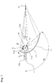
- FIG. 7 is a sectional view of describing an overview configuration and action of the light source apparatus according to the first embodiment of the present invention.
- FIG. 8 is a sectional view of describing an overview configuration of the lighting apparatus according to a second embodiment of the present invention.
- FIG. 9 is a sectional view of describing an overview configuration of the lighting apparatus according to the second embodiment of the present invention.
- FIG. 10 is a sectional view showing an overview configuration of a projection display apparatus according to the second embodiment of the present invention.
- FIG. 11 is a sectional view of an optical system using multiple conventional light source apparatuses
- FIG. 12 is a sectional view of the light source apparatus using multiple concave mirrors shown as a first conventional example
- FIG. 13 is a schematic view of describing an effect of the optical system using a mirror for a composite portion of multiple conventional light source apparatuses
- FIG. 14 is a schematic view of describing an effect of the optical system using the mirror for the composite portion of the multiple conventional light source apparatuses of the first conventional example
- FIG. 15 is a sectional view of the light source apparatus using the multiple concave mirrors shown as a second conventional example
- FIG. 16 is a sectional view of the optical system using the multiple conventional light source apparatuses
- FIG. 17 is a sectional view of describing an overview configuration of the lighting apparatus according to the second embodiment of the present invention.
- FIG. 18 is a sectional view of describing an overview configuration of the lighting apparatus according to a third embodiment of the present invention.
- FIG. 19 is a sectional view of describing an overview configuration of the lighting apparatus according to the third embodiment of the present invention.
- FIG. 1 shows an overview configuration of a light source apparatus according to the first embodiment.
- This light source apparatus is configured by a lamp (an example of the lamp or light generating means of the present invention) 11 , an ellipsoidal mirror (an example of a first concave mirror of the present invention) 12 and a spherical mirror (an example of a second concave mirror of the present invention) 13 .
- the lamp 11 is configured by a lamp light-emitting portion 111 having a substantially spherical vessel portion including a source of luminescence positioned correspondingly to a focal position mentioned later and generating light, and light transmission planes 111 a and 111 b containing the source of luminescence and transmitting the light therefrom to the outside, and a pair of ends 111 c and 111 d including electrodes of the source of luminescence and having a form projecting from the lamp light-emitting portion 111 .
- the vessel portion and ends 111 c and 111 d of the lamp light-emitting portion 111 are integrally formed from the same vessel body.
- the lamp 11 it is possible to use a xenon lamp having a light-emitting portion form as the source of luminescence very close to a point source and capable of large optical output, a metal halide lamp of high luminous efficiency, a mercury lamp having an ultrahigh voltage in the lamp light-emitting portion (arc tube) when lit up, and a halogen lamp.
- the reflection plane of the ellipsoidal mirror 12 Of the two focuses of the reflection plane of the ellipsoidal mirror 12 , one is placed to coincide with the source of luminescence of the lamp light-emitting portion 111 . Therefore, the light radiated from the light transmission plane 111 b and collected by the ellipsoidal mirror 12 is focused on the outgoing opening side of the ellipsoidal mirror 12 so as to form an optical spot on the other focus.
- the ellipsoidal mirror 12 is in a form of non-rotation symmetry to an optical axis 14 thereof, that is, a reference axis connecting the focal position F 1 to the focal position F 2 . Furthermore, a part of the reflection plane of the ellipsoidal mirror 12 exists around the optical axis 14 shown in FIG. 1 , and a further part thereof is formed to be opposed to the light transmission plane 111 a by going round to the back of a lamp 111 .
- the spherical mirror 13 is also in the form of non-rotation symmetry to the optical axis 14 , and the reflection plane thereof is opposed to the light transmission plane 111 a of the lamp light-emitting portion 111 so as to cover a portion without the ellipsoidal mirror 12 in a range reachable by radiation light therefrom.
- the center of the reflection plane of the spherical mirror 13 coincides with the focal position F 1 .
- the ellipsoidal mirror 12 can collect the light radiated from the light transmission plane 111 b and the light transmission plane 111 a
- the spherical mirror 13 has a configuration capable of reflecting the light radiated from the light transmission plane 111 a.
- a distance from the focal position F 1 of the ellipsoidal mirror 12 to the reflection plane of the spherical mirror 13 that is, a radius of curvature R of the spherical mirror 13 is shorter than the distance from a focal length of the ellipsoidal mirror 12 having the lamp light-emitting portion 111 to the focal position F 2 of the ellipsoidal mirror 12 at which luminous fluxes emitted from the lamp light-emitting portion 111 is collected by the ellipsoidal mirror 12 to form a spot, that is, an inter-focus distance L of the ellipsoidal mirror 12 .
- the optical axis 14 is placed to penetrate the lamp 11 , where the ends 111 c and 111 d are formed around the optical axis 14 .
- FIG. 2 shows a three-dimensional overview form of the light source apparatus.
- the sectional view of FIG. 1 is based on a line A–A′ of FIG. 2 .
- the line A–A′ is located in the same plane as the optical axis 14 , and divides the light source apparatus in two from overhead.
- the light source apparatus shown in FIG. 1 An action of the light source apparatus shown in FIG. 1 will be described.
- the light reflected on the ellipsoidal mirror 12 is focused on the outgoing opening side of the ellipsoidal mirror 12 so as to form the optical spot on the focal position F 2 existing on the outgoing opening side of the ellipsoidal mirror 12 .
- the luminous flux radiated from the source of luminescence of the lamp light-emitting portion 111 is formed by the light radiated from the light transmission plane 111 b and the light transmission plane 111 a.
- the light radiated from the light transmission plane 111 a and reflected on the spherical mirror 13 is returned to the lamp light-emitting portion 111 of the lamp 11 again. It passes the vicinity of the lamp light-emitting portion 111 , and is reflected thereafter on the ellipsoidal mirror 12 so as to be focused on the second focus F 2 of the ellipsoidal mirror 12 together with direct light from the lamp light-emitting portion 111 .
- the light source apparatus has the configuration in which the ellipsoidal mirror 12 is in rotation asymmetry to the optical axis 14 , where the light directly radiated from the lamp 11 is reflected to form the luminous fluxes in rotation asymmetry and the light radiated from the lamp 11 and not reflected on the ellipsoidal mirror 12 is reflected on the ellipsoidal mirror 12 again by the spherical mirror 13 . Therefore, an amount of luminous fluxes close to the luminous fluxes in rotation symmetry is secured even in the case of the luminous fluxes in rotation asymmetry.
- the ellipsoidal mirror 12 is formed in rotation asymmetry to the optical axis 14 , and the reflection plane is formed to go round to the back of the lamp light-emitting portion 111 so as to directly collect the light from the same light transmission plane as that reflecting the light reflected on the spherical mirror 13 .
- the spherical mirror 13 it is not necessary for the spherical mirror 13 to reflect all the radiation light from the light transmission plane 111 a as with the light source apparatus of the second conventional example of FIG. 15 . It is thereby possible to prevent the reflected light from being radiated outside without getting collected so as to obtain a sufficient amount of luminous fluxes without changing a substantial size of the ellipsoidal mirror 12 .
- the light source apparatus has the configuration in which the radius of curvature R of the spherical mirror 13 is shorter than the inter-focus distance L of the ellipsoidal mirror 12 , which has the effect of keeping the size of the light source apparatus minimum while securing a maximum amount of luminous fluxes. This has the following reason.
- the spherical mirror 13 at a position backed out until its reflection plane substantially coincides with the focal position F 2 as a convergent point of outgoing beams emitted from the ellipsoidal mirror 12 and further provide an opening of substantially the same size as a focusing spot at a position corresponding to the focal position F 2 on the reflection plane of the spherical mirror 13 .
- the size of the light source apparatus itself becomes larger because the radius of curvature of the spherical mirror 13 is fixed even if a focusing angle of the ellipsoidal mirror 12 is changed.
- FIGS. 6 and 7 show sectional views on a vertical plane at which the angle for the spherical mirror 13 to take in the radiation light from the lamp 111 becomes the largest.
- the sectional views show the section at which the angle of viewing the spherical mirror 13 from the light source 111 becomes the largest.
- the reflection plane defined by the angle ⁇ reflects the radiation light from the light transmission plane 111 b
- the reflection plane defined by the angle ⁇ reflects the light from the light transmission plane 111 a.
- the spherical mirror 13 is formed on a surface of the vessel portion of the lamp light-emitting portion 111 or in proximity thereto within the range scarcely blocking the light reflected on the ellipsoidal mirror 12 as shown in FIG. 7 , that is, in the case where the reflection plane of the spherical mirror 13 is placed closer to the light source 111 than the reflection plane of the ellipsoidal mirror 12 .
- ⁇ is positive.
- This provides the configuration in which the reflection plane of the ellipsoidal mirror 12 is vertically astride the optical axis 14 on both sides thereof in FIGS. 6 and 7 . Furthermore, it provides the configuration in which the reflection plane is opposed not only to the light transmission plane 111 b but also to the light transmission plane 111 a by straddling the end 111 c of the lamp 11 .
- the ellipsoidal mirror 12 is vertically astride the optical axis 14 on both sides thereof and the reflection plane is opposed not only to the light transmission plane 111 b but also to the light transmission plane 111 a .
- the ellipsoidal mirror 12 it is thereby possible for the ellipsoidal mirror 12 to directly collect the light from the light source 111 at a large angle.
- the spherical mirror 13 can be small-size since it has only to collect a small amount of the remaining light which cannot be completely collected by the ellipsoidal mirror 12 out of the light from the light transmission plane 111 a . Therefore, in this state, the light radiated from the light source 111 and heading for the ellipsoidal mirror 12 without suffering a loss to be focused on the second focus F 2 becomes the largest.
- the formula (1) indicates the condition for the reflection plane of the ellipsoidal mirror 12 to be in non-rotation symmetry to the optical axis 14 .
- the light reflected on the spherical mirror 13 reaches the area in which the reflection plane of the ellipsoidal mirror 12 does not exist so that the optical usable efficiency cannot be improved.
- the formulas (3) and (5) indicate the ranges in which the spherical mirror 13 can collect the light.
- the formula (3) is the case where the spherical mirror 13 is outside the reflection plane of the ellipsoidal mirror 12 as shown in FIG. 6 . Therefore, it shows the range capable of taking in the radiation light from the lamp 11 at the maximum and rendering the angle of the spherical mirror 13 small.
- the size of the light source apparatus becomes larger than the case where it is in proximity to the vessel surface of the lamp 11 in the example of FIG. 7 .
- the formula (5) is the case where, as shown in FIG. 7 , the spherical mirror 13 is on the lamp vessel surface substantially coinciding with the light transmission plane 111 a or in proximity thereto and is placed in the luminous fluxes formed by the ellipsoidal mirror 12 . Therefore, the size of the light source apparatus is hardly changed by an angular range of the spherical mirror 13 . Thus, it is desirable to provide the angular range placing more importance on the improved efficiency.
- FIG. 1 shows the case of using one piece of the spherical mirror 13 .
- the ellipsoidal mirror in a form having some locations cut off from the ellipsoidal mirror in rotation symmetry to the optical axis 14 , however, it is possible, by using multiple spherical mirrors, to collect the radiation light from the lamp 11 reaching the area not coverable by the ellipsoidal mirror even if the ellipsoidal mirror has a complicated opening form so as to improve the optical usable efficiency of the light source apparatus.
- a light source apparatus 100 As shown in FIG. 3 , it is possible to place a light source apparatus 100 , mirrors, a rod integrator 101 made of glass poles or mirrors glued together, and optical means 102 such as a lens of this embodiment at predetermined positions so as to obtain a lighting apparatus of this embodiment of converting the light emitted from the light source apparatus 100 to predetermined approximately parallel light.
- FIG. 4 it may also be the lighting apparatus using a lens array 103 having multiple lenses two-dimensionally placed rather than the lighting apparatus using the rod integrator having the glass poles or mirrors glued together.
- FIG. 5 it is possible to additionally provide a field lens 104 , a light modulation device 105 and a projection lens 106 to the lighting apparatus 100 so as to obtain a projection display apparatus of this embodiment.
- the light modulation device 105 a reflective light valve, a transmissive light valve, a mirror panel capable of changing a direction of reflection with small mirrors placed like an array, and the light modulation device of an optical writing method.
- FIGS. 3 , 4 and 5 show the lens as the optical means of converting the radiation light from the light source apparatus to illumination light, it may also be the optical means using the mirrors and a prism in addition to the lens or the optical system including an optical component combining multiple lenses.
- FIG. 5 shows the configuration having just one transmissive light valve as the light modulation device, it may also be the configuration having multiple light modulation devices.
- the lamp 11 it is possible to have the lamp 11 , ellipsoidal mirror 12 and spherical mirror 13 and place the spherical mirror at the position capable of collecting the light not collectable by the ellipsoidal mirror in the form of non-rotation symmetry to the optical axis so as to obtain the light source apparatus of high efficiency and small size.
- the ellipsoidal mirror 12 used as the first concave mirror.
- it may be any reflecting surface mirror having a quadratic surface, where a reflecting surface mirror in the form combining a parabolic mirror and multiple ellipsoidal mirrors may also be used.
- the first concave mirror is not limited to the quadratic surface but may also be formed by multiple planes or curved surfaces, such as a Fresnel mirror.
- the spherical mirror is used as the second concave mirror.
- it may be any reflecting surface mirror having a quadratic surface capable of efficiently reflecting lamp radiation light to the proximity of the lamp light-emitting portion, where the reflecting surface mirror in the form combining the ellipsoidal mirror and multiple spherical mirrors may also be used.
- the first concave mirror it is not limited to the quadratic surface but may also be formed by multiple planes or curved surfaces, such as the Fresnel mirror.
- FIGS. 8 and 10 show overview configurations of the lighting apparatus and the projection display apparatus according to this embodiment.
- the light source apparatus 100 is the same as that in the first embodiment, and so a description thereof will be omitted.
- a multi-lamp optical system as shown in FIG. 11 uses multiple light source apparatuses to be able to perform brighter illumination, combines the luminous fluxes emitted from each of the multiple light source apparatuses and has them incident on one piece of rod integrator or lens optical system to perform the illumination.
- FIG. 13 there is a configuration, as shown in FIG. 13 , in which a pair of light source apparatuses is placed to have their reflection planes opposed to each other and there is a mirror 200 placed immediately anterior to the incident side opening 2 a of the rod integrator 2 at an angle of guiding the luminous fluxes emitted from multiple light source apparatuses 1 to the incident side opening 2 a of the rod integrator 2 .
- the concave mirror 1 there is no physical interference of the concave mirror 1 itself. If the mirror 200 is placed to reflect all the luminous fluxes emitted from the concave mirror 1 onto the rod integrator 2 side, however, there are the luminous fluxes not reflected on the incident side opening 2 a due to the physics interference of the mirror 200 so that the concave mirror 1 is not substantially used in certain areas (indicated by dotted lines in FIG. 13 ). In this case, the ellipsoidal mirror has no interfering portion, and so the light incident on a mirror interfering portion is not consequently used even though the ellipsoidal mirror in rotation symmetry to the optical axis can be placed.
- FIG. 14 is a diagram showing the configuration of a multi-lamp optical system using the light source apparatus of a conventional configuration as in FIG. 12 as the light source apparatus of the optical system of FIG. 13 .
- the first concave mirror 6 not substantially used (indicated by the dotted lines in FIG. 13 ) as with the concave mirror of FIG. 13 .
- the lighting apparatus according to the second embodiment of the present invention solves the above problems by using the light source apparatus of the first embodiment as the lighting apparatus.
- FIG. 8 shows the lighting apparatus of the multi-lamp optical system according to the second embodiment of the present invention using the light source apparatus of the first embodiment of the present invention.
- each light source apparatus 100 is placed so that the optical axes 14 coincide in the same plane to be on the same line in FIG. 8 .
- the light source apparatus 100 is placed to orient a smaller reflection plane of the ellipsoidal mirror 12 toward an unused part of the portion interfered with by the mirror 200 and have a spherical mirror 1 positioned in the unused part.
- the mirror 200 is equivalent to light guiding means of the present invention.
- the radiation light from the lamp 11 incident on the spherical mirror 13 is returned to pass through the vicinity of the lamp light-emitting portion 111 , and is emitted thereafter onto the mirror 200 side via the reflection plane of the ellipsoidal mirror 12 capable of being used by the mirror 200 and the rod integrator 101 . Therefore, it becomes the luminous fluxes suffering no loss after the rod integrator 101 so as to improve the optical usable efficiency of the luminous fluxes emitted from the light source apparatus.
- the position of providing the reflection plane having the smallest angle (corresponding to an angle ⁇ shown in FIGS. 6 and 7 ) of the focusing angles of the ellipsoidal mirror 12 to the optical axis 14 is placed to approximately coincide with the position in the luminous flux closest to an adjacent luminous flux emitted from one of the light source apparatuses when the luminous fluxes emitted from the two light source apparatuses 100 come close before getting incident on the rod integrator 101 .
- the number of effective luminous fluxes directly collectable from the lamp light-emitting portion 111 by the ellipsoidal mirror 12 becomes the largest. It is also possible, with the spherical mirror 13 , to collect the luminous fluxes from the lamp light-emitting portion 111 not collectable by the ellipsoidal mirror 12 .
- the loss occurs due to light absorption and light scattering of light-emitting materials and materials configuring the lamp 11 .
- the light having passed through the vicinity of a luminous body without being absorbed or scattered, even though not all of the luminous fluxes reflected on the spherical mirror 13 reaches the ellipsoidal mirror 12 .
- the light collection efficiency as the light source apparatus is improved because of the ellipsoidal mirror 12 having the reflection plane formed in non-rotation symmetry to the optical axis 14 and astride the optical axis 14 . Therefore, the radiation light from the lamp 11 unusable so far can be used so as to improve the optical usable efficiency as the lighting apparatus.
- the focal length L of the ellipsoidal mirror 13 can also be reduced. Therefore, it is possible to form a smaller optical spot for an incident side opening end 101 a of the rod integrator 101 so as to improve the light collection efficiency from the rod integrator 101 onward.
- FIG. 8 shows the example in which the light source apparatus 100 is placed to orient a smaller reflection plane of the ellipsoidal mirror 12 toward an unused part of the portion interfered with by the mirror 200 and have a spherical mirror 1 positioned in the unused part.
- each light source apparatus 100 it is also feasible to place each light source apparatus 100 so as to reverse positional relation between the ellipsoidal mirror 12 and the spherical mirror 13 .
- it is necessary, for the sake of preventing the interference of the mirror 200 to take a larger distance between the light source apparatus 100 and the rod integrator 101 .
- FIG. 8 shows the lighting apparatus using the rod integrator 101 made of glass poles or mirrors glued together as an example. However, it may also be the lighting apparatus using the lens array 103 having multiple lenses two-dimensionally placed as shown in FIG. 9 .
- the light modulation device 105 it is possible to use as the light modulation device 105 the reflective light valve, the transmissive light valve and the light modulation device of an optical writing method.
- FIGS. 8 , 9 and 10 show the lens as the optical means of converting to the illumination light, it may also be the optical means using the mirrors and prism in addition to the lens or the optical system including an optical component combining multiple lenses.
- FIGS. 5 and 8 to 10 show the configuration having just one transmissive light valve as the light modulation device, it may also be the configuration having multiple light modulation devices. Furthermore, although it is not shown, it may be the configuration using the prism, filter and mirror capable of performing color separation and color composition.
- the second embodiment it is possible, on the lighting apparatus using multiple light source apparatuses having the lamp, ellipsoidal mirror and spherical mirror, to place the spherical mirror at the position capable of collecting the light not collectable by the ellipsoidal mirror in the form of non-rotation symmetry to the optical axis so as to obtain the light source apparatus of high efficiency.
- FIG. 18 shows the configuration of the lighting apparatus according to a third embodiment of the present invention.
- the rod integrator 101 , a relay lens 102 and the light modulation device 105 are the same as the conventional examples and the second embodiment.
- it has the configuration in which the light source apparatus according to the first embodiment is used as the light source apparatus of the lighting apparatus of the conventional example shown in FIG. 11 .
- the pair of light source apparatuses 100 is placed to have their spherical mirrors 13 opposed to each other, and the rod integrator 101 is placed at an intersection which is a point in space at which the optical axes 14 of the light source apparatuses 100 intersect.
- the lighting apparatus of this embodiment has the same optical operation as the conventional example of FIG. 11 . It uses the light source apparatuses of the first embodiment as the pair of light source apparatuses 100 , and the luminous fluxes emitted from the light source apparatuses 100 directly reach the incident side opening end 101 a of the rod integrator 101 .
- the optical axes 14 of the light source apparatuses of this embodiment are oblique as with the conventional examples, and so a problem remains, such as difficulty in adjustment of optical axis fitting. It is possible, however, to radiate all the luminous fluxes in non-rotation symmetry to the optical axis 14 to the rod integrator 101 .
- FIG. 18 shows the configuration of placing the pair of light source apparatuses 100 to have the spherical mirrors 13 opposed to each other. It is also possible, as shown in FIG. 19 , to place them to have the ellipsoidal mirrors 12 opposed to each other.
- the luminous fluxes incident on the rod integrator 101 it is feasible, of the luminous fluxes incident on the rod integrator 101 , to intensively have the luminous fluxes substantially almost parallel to the optical axis of the rod integrator 101 incident on the incident side opening end 101 a and increase a substantial amount of luminous fluxes from the rod integrator 101 onward in the lighting apparatus.
- the ellipsoidal mirror is used as the first concave mirror.
- it may be any reflecting surface mirror having a quadratic surface, where a reflecting surface mirror in the form combining the parabolic mirror and multiple ellipsoidal mirrors may also be used.
- the spherical mirror is used as the second concave mirror.
- it may be any reflecting surface mirror having a quadratic surface capable of efficiently reflecting the lamp radiation light to the proximity of the lamp light-emitting portion, where the reflecting surface mirror in the form combining the ellipsoidal mirror and multiple spherical mirrors may also be used.
- the lamp 11 is an example of the lamp or light generating means of the present invention
- the spherical vessel portion of the lamp light-emitting portion 111 except the source of luminescence is an example of the spherical vessel portion of the present invention
- the ends 111 c and 111 d are an example of the pair of ends of the present invention
- the light transmission plane 111 a of the lamp light-emitting portion 111 is an example of a first opposed plane of the present invention
- the light transmission plane 111 b is an example of a second opposed plane of the present invention.
- the light generating means of the present invention does not need to be implemented as the lamp having the vessel body as in the embodiments. It may also be implemented by another light source such as a light-emitting diode. In the case where it is the lamp, it does not have to be configured by the spherical vessel portion and the ends. For instance, it may also be in a substantially spherical or ellipsoidal form consisting only of the spherical vessel portion having the light transmission plane.
- the light generating means of the present invention is not limited by its concrete configuration and form as long as its source of luminescence can form the focus of the first concave mirror and the reference axis of the present invention.
- the present invention it is possible to provide the light source apparatus capable of realizing high optical usable efficiency which is not lowered by miniaturizing it and also provide the lighting apparatus and projection display apparatus of high optical usable efficiency by having the light source apparatus.
Landscapes
- Physics & Mathematics (AREA)
- General Physics & Mathematics (AREA)
- Engineering & Computer Science (AREA)
- General Engineering & Computer Science (AREA)
- Projection Apparatus (AREA)
- Non-Portable Lighting Devices Or Systems Thereof (AREA)
Abstract
Description
α>β>0 (Formula 1)
α+β≧180 degrees (Formula 2)
0<θ≦γ−β. (Formula 3)
α>β>0 (Formula 1)
αβ≧180 degrees (Formula 2)
0<θ≦180 degrees. (Formula 4)
- 11 Lamp
- 12 Ellipsoidal mirror
- 13 Spherical mirror
- 14 Optical axis
- 111 Lamp light-emitting portion
- 100 Light source apparatus
- 101 Rod integrator
- F1 First focal position
- F2 Second focal position
α>β>0 (1)
(Formula 2)
α+β≧180 degrees (2)
(Formula 3)
0<θ≦γ−β (3)
α>β>0 (1)
(Formula 2)
α+β≧180 degrees (4)
(Formula 4)
0<θ≦180 degrees (5)
As for the condition of
Claims (14)
α>β>0 (Formula 1)
α+β≧180 degrees (Formula 2)
0<≦γ−β. (Formula 3)
α>β>0 (Formula 1)
α+β≧180 degrees (Formula 2)
0<θ≦180 degrees. (Formula 4)
Applications Claiming Priority (3)
| Application Number | Priority Date | Filing Date | Title |
|---|---|---|---|
| JP2003-114162 | 2003-04-18 | ||
| JP2003114162 | 2003-04-18 | ||
| PCT/JP2004/005422 WO2004092823A1 (en) | 2003-04-18 | 2004-04-15 | Light source unit, illuminator and projection display |
Publications (2)
| Publication Number | Publication Date |
|---|---|
| US20060203497A1 US20060203497A1 (en) | 2006-09-14 |
| US7213944B2 true US7213944B2 (en) | 2007-05-08 |
Family
ID=33296143
Family Applications (1)
| Application Number | Title | Priority Date | Filing Date |
|---|---|---|---|
| US10/553,489 Expired - Lifetime US7213944B2 (en) | 2003-04-18 | 2004-04-15 | Light source apparatus, lighting apparatus and projection display apparatus |
Country Status (4)
| Country | Link |
|---|---|
| US (1) | US7213944B2 (en) |
| JP (2) | JP4251499B2 (en) |
| CN (1) | CN1809785B (en) |
| WO (1) | WO2004092823A1 (en) |
Cited By (9)
| Publication number | Priority date | Publication date | Assignee | Title |
|---|---|---|---|---|
| US20060285088A1 (en) * | 2005-06-17 | 2006-12-21 | Nobuyuki Kimura | Light source unit and projection type image display apparatus having the same |
| US20080024740A1 (en) * | 2006-07-26 | 2008-01-31 | Eun Seong Seo | Illumination device, and projection system including the same |
| US20100053971A1 (en) * | 2008-08-29 | 2010-03-04 | Abl Ip Holding Llc | Asymmetric Lighting Systems and Applications Thereof |
| US20100053564A1 (en) * | 2008-09-04 | 2010-03-04 | Seiko Epson Corporation | Illuminator and projector |
| US20100208215A1 (en) * | 2009-02-18 | 2010-08-19 | Seiko Epson Corporation | Light source device and projector |
| US20100265719A1 (en) * | 2008-08-29 | 2010-10-21 | Abdelsamed Yaser S | Luminaires having enhanced light distribution and applications thereof |
| US20100302510A1 (en) * | 2009-06-02 | 2010-12-02 | Seiko Epson Corporation | Light source device, illumination system, and projector |
| US20120281425A1 (en) * | 2011-05-03 | 2012-11-08 | Osram Sylvania Inc. | Optic emitting a simulated floating band of light |
| US9772560B2 (en) | 2014-08-05 | 2017-09-26 | Canon Kabushiki Kaisha | Light source apparatus, illumination device, exposure apparatus, and device manufacturing method |
Families Citing this family (26)
| Publication number | Priority date | Publication date | Assignee | Title |
|---|---|---|---|---|
| US7131736B2 (en) * | 2002-05-17 | 2006-11-07 | Bierhuizen Serge J A | Efficient illumination systems for reduced étendue color video projection systems |
| US7364326B2 (en) * | 2004-12-06 | 2008-04-29 | Texas Instruments Incorporated | Multiple light source illumination for image display systems |
| JP4940551B2 (en) * | 2005-01-25 | 2012-05-30 | カシオ計算機株式会社 | Light source device and projector using the same |
| JP4524265B2 (en) * | 2005-03-30 | 2010-08-11 | 三星電子株式会社 | Illumination unit and image projection apparatus employing the same |
| CN101189472B (en) * | 2005-06-30 | 2010-05-26 | 微阳有限公司 | Dual paraboloid reflector and dual ellipsoid reflector systems with optimized magnification |
| WO2007032153A1 (en) * | 2005-09-12 | 2007-03-22 | Matsushita Electric Industrial Co., Ltd. | Projection type image display device |
| JP2007329102A (en) * | 2006-06-09 | 2007-12-20 | Victor Co Of Japan Ltd | Light source device and image display device |
| JP2007329103A (en) * | 2006-06-09 | 2007-12-20 | Victor Co Of Japan Ltd | Light source device and image display device |
| RU2457394C2 (en) * | 2007-04-24 | 2012-07-27 | Конинклейке Филипс Электроникс Н.В. | Lamp and reflector |
| US8672520B2 (en) * | 2008-01-25 | 2014-03-18 | Osram Gesellschaft Mit Beschraenkter Haftung | AC voltage reflector lamp |
| JP2011082057A (en) * | 2009-10-08 | 2011-04-21 | Seiko Epson Corp | Light source device, projector |
| IL209227A0 (en) | 2010-11-10 | 2011-01-31 | Uri Neta | Common focus energy sources multiplexer |
| JP2013207163A (en) * | 2012-03-29 | 2013-10-07 | Orc Manufacturing Co Ltd | Light source device |
| CN105102887A (en) * | 2013-03-26 | 2015-11-25 | 皇家飞利浦有限公司 | Lighting device and luminaire |
| JP2016514885A (en) * | 2013-03-26 | 2016-05-23 | コーニンクレッカ フィリップス エヌ ヴェKoninklijke Philips N.V. | Lighting device and lighting fixture |
| CN105102886A (en) * | 2013-03-26 | 2015-11-25 | 皇家飞利浦有限公司 | Lighting device, adjustment kit and luminaire |
| US9651730B2 (en) | 2013-03-26 | 2017-05-16 | Philips Lighting Holding B.V. | Lighting device and luminaire |
| CN103363353B (en) * | 2013-06-20 | 2015-06-03 | 中微光电子(潍坊)有限公司 | LED light source |
| JP5684438B1 (en) * | 2013-08-06 | 2015-03-11 | オリンパス株式会社 | Light source optics, fiber light source, microscope and automotive headlamp |
| CN107654958B (en) * | 2014-04-30 | 2020-02-07 | 王正 | Vehicle lamp module |
| JP5754532B1 (en) * | 2014-05-09 | 2015-07-29 | 岩崎電気株式会社 | Light guide component and light source device |
| CN104566033B (en) * | 2014-12-30 | 2016-09-28 | 东莞市沃德普自动化科技有限公司 | A kind of detection is with focusing on light fixture |
| CN107063115A (en) * | 2017-01-17 | 2017-08-18 | 天津众科创谱科技有限公司 | A kind of light path system of Kelvin probe |
| JP2018199096A (en) * | 2017-05-25 | 2018-12-20 | 岩崎電気株式会社 | Ultraviolet irradiator |
| CN108919479B (en) * | 2018-06-22 | 2024-06-04 | 深圳市润沃自动化工程有限公司 | Laser reflection imaging device |
| CN112034620A (en) * | 2019-06-04 | 2020-12-04 | 怡利电子工业股份有限公司 | Target reflection type diffusion sheet head-up display device |
Citations (11)
| Publication number | Priority date | Publication date | Assignee | Title |
|---|---|---|---|---|
| JPH01122501A (en) | 1987-11-06 | 1989-05-15 | Honda Motor Co Ltd | Downward head light for vehicle |
| US4956759A (en) | 1988-12-30 | 1990-09-11 | North American Philips Corporation | Illumination system for non-imaging reflective collector |
| US5075827A (en) * | 1990-10-31 | 1991-12-24 | Smith David H | Indirect light fixture amplification reflector system |
| JPH0540223A (en) | 1991-08-07 | 1993-02-19 | Canon Inc | Lighting device |
| US5526237A (en) * | 1993-12-10 | 1996-06-11 | General Electric Company | Lighting system for increasing brightness to a light guide |
| JP2543260B2 (en) | 1991-03-11 | 1996-10-16 | 松下電器産業株式会社 | Lighting equipment |
| JP2000171901A (en) | 1998-09-28 | 2000-06-23 | Matsushita Electric Ind Co Ltd | Lighting optical device and projection type display device |
| JP3151734B2 (en) | 1992-05-26 | 2001-04-03 | 株式会社日立製作所 | Light source unit and display device using the same |
| JP2002258212A (en) | 2001-03-02 | 2002-09-11 | Ricoh Co Ltd | Lighting system for projector |
| JP3350003B2 (en) | 1999-10-01 | 2002-11-25 | エヌイーシービューテクノロジー株式会社 | Light source device for projector |
| US6547422B2 (en) * | 2001-08-08 | 2003-04-15 | Prokia Technology Co., Ltd. | Illuminating module for a display apparatus |
-
2004
- 2004-04-15 JP JP2005505456A patent/JP4251499B2/en not_active Expired - Fee Related
- 2004-04-15 US US10/553,489 patent/US7213944B2/en not_active Expired - Lifetime
- 2004-04-15 WO PCT/JP2004/005422 patent/WO2004092823A1/en active Application Filing
- 2004-04-15 CN CN2004800103233A patent/CN1809785B/en not_active Expired - Fee Related
-
2008
- 2008-10-17 JP JP2008269171A patent/JP4914419B2/en not_active Expired - Fee Related
Patent Citations (13)
| Publication number | Priority date | Publication date | Assignee | Title |
|---|---|---|---|---|
| JPH01122501A (en) | 1987-11-06 | 1989-05-15 | Honda Motor Co Ltd | Downward head light for vehicle |
| US4956759A (en) | 1988-12-30 | 1990-09-11 | North American Philips Corporation | Illumination system for non-imaging reflective collector |
| JP2730782B2 (en) | 1988-12-30 | 1998-03-25 | フィリップス エレクトロニクス ネムローゼ フェンノートシャップ | Lighting equipment |
| US5075827A (en) * | 1990-10-31 | 1991-12-24 | Smith David H | Indirect light fixture amplification reflector system |
| JP2543260B2 (en) | 1991-03-11 | 1996-10-16 | 松下電器産業株式会社 | Lighting equipment |
| JPH0540223A (en) | 1991-08-07 | 1993-02-19 | Canon Inc | Lighting device |
| JP3151734B2 (en) | 1992-05-26 | 2001-04-03 | 株式会社日立製作所 | Light source unit and display device using the same |
| US5526237A (en) * | 1993-12-10 | 1996-06-11 | General Electric Company | Lighting system for increasing brightness to a light guide |
| JP2000171901A (en) | 1998-09-28 | 2000-06-23 | Matsushita Electric Ind Co Ltd | Lighting optical device and projection type display device |
| US6224217B1 (en) * | 1998-09-28 | 2001-05-01 | Matsushita Electric Industrial Co., Ltd. | Optical illumination apparatus and image projection apparatus |
| JP3350003B2 (en) | 1999-10-01 | 2002-11-25 | エヌイーシービューテクノロジー株式会社 | Light source device for projector |
| JP2002258212A (en) | 2001-03-02 | 2002-09-11 | Ricoh Co Ltd | Lighting system for projector |
| US6547422B2 (en) * | 2001-08-08 | 2003-04-15 | Prokia Technology Co., Ltd. | Illuminating module for a display apparatus |
Non-Patent Citations (1)
| Title |
|---|
| International Search Report for PCT/JP 2004/005422, dated Jun. 1, 2004. |
Cited By (17)
| Publication number | Priority date | Publication date | Assignee | Title |
|---|---|---|---|---|
| US7771056B2 (en) * | 2005-06-17 | 2010-08-10 | Hitachi, Ltd. | Light source unit and projection type image display apparatus having the same |
| US20060285088A1 (en) * | 2005-06-17 | 2006-12-21 | Nobuyuki Kimura | Light source unit and projection type image display apparatus having the same |
| US20080024740A1 (en) * | 2006-07-26 | 2008-01-31 | Eun Seong Seo | Illumination device, and projection system including the same |
| US7807958B2 (en) * | 2006-07-26 | 2010-10-05 | Lg Electronics Inc. | Switch for an illumination device, and projection system including the same |
| US8439525B2 (en) | 2008-08-29 | 2013-05-14 | Abl Ip Holding Llc | Luminaires having enhanced light distribution and applications thereof |
| US20100265719A1 (en) * | 2008-08-29 | 2010-10-21 | Abdelsamed Yaser S | Luminaires having enhanced light distribution and applications thereof |
| US20100053971A1 (en) * | 2008-08-29 | 2010-03-04 | Abl Ip Holding Llc | Asymmetric Lighting Systems and Applications Thereof |
| US20100053564A1 (en) * | 2008-09-04 | 2010-03-04 | Seiko Epson Corporation | Illuminator and projector |
| US8308307B2 (en) * | 2008-09-04 | 2012-11-13 | Seiko Epson Corporation | Illuminator and projector |
| US20100208215A1 (en) * | 2009-02-18 | 2010-08-19 | Seiko Epson Corporation | Light source device and projector |
| US8287139B2 (en) * | 2009-02-18 | 2012-10-16 | Seiko Epson Corporation | Light source device and projector |
| US20100302510A1 (en) * | 2009-06-02 | 2010-12-02 | Seiko Epson Corporation | Light source device, illumination system, and projector |
| US8506128B2 (en) * | 2009-06-02 | 2013-08-13 | Seiko Epson Corporation | Light source device, illumination system, and projector |
| US20120281425A1 (en) * | 2011-05-03 | 2012-11-08 | Osram Sylvania Inc. | Optic emitting a simulated floating band of light |
| US8545072B2 (en) * | 2011-05-03 | 2013-10-01 | Osram Sylvania Inc. | Optic emitting a simulated floating band of light |
| US9772560B2 (en) | 2014-08-05 | 2017-09-26 | Canon Kabushiki Kaisha | Light source apparatus, illumination device, exposure apparatus, and device manufacturing method |
| US10216092B2 (en) | 2014-08-05 | 2019-02-26 | Canon Kabushiki Kaisha | Light source apparatus, illumination device, exposure apparatus, and device manufacturing method |
Also Published As
| Publication number | Publication date |
|---|---|
| CN1809785B (en) | 2010-10-27 |
| JP4914419B2 (en) | 2012-04-11 |
| US20060203497A1 (en) | 2006-09-14 |
| JP4251499B2 (en) | 2009-04-08 |
| JPWO2004092823A1 (en) | 2006-07-06 |
| JP2009020537A (en) | 2009-01-29 |
| CN1809785A (en) | 2006-07-26 |
| WO2004092823A1 (en) | 2004-10-28 |
Similar Documents
| Publication | Publication Date | Title |
|---|---|---|
| US7213944B2 (en) | Light source apparatus, lighting apparatus and projection display apparatus | |
| JP4808893B2 (en) | Image projection apparatus and light collection system | |
| JP3992053B2 (en) | Illumination device and projection display device | |
| JP4972883B2 (en) | Optical unit and projection-type image display device | |
| JP2002055393A (en) | Light source device, illuminator and projection type display device | |
| JP4235829B2 (en) | LIGHTING DEVICE AND PROJECTOR HAVING THE LIGHTING DEVICE | |
| US6246170B1 (en) | Light source apparatus with a spherical optical member | |
| JP2010062019A (en) | Illuminator, and projector | |
| US20040021827A1 (en) | Lamp, polarization converting optical system, condensing optical system and image display device | |
| JPH08511902A (en) | Lamp with reflector | |
| JP2006253120A (en) | Light source device | |
| US20050243572A1 (en) | Lamp, condensing optical system, and image display device | |
| US7736028B2 (en) | Light source apparatus, lighting apparatus and projection display apparatus | |
| JP5373373B2 (en) | Lamp device | |
| WO2013118272A1 (en) | Illumination optical system and projection-type display device | |
| JP5036102B2 (en) | Lighting device | |
| JP2001272726A (en) | Optical device and projection type display device using the same | |
| JPH08129155A (en) | Projection type picture display device | |
| JP2010026262A (en) | Lighting optical device and projection type display device using the same | |
| JPH10311962A (en) | Light source device | |
| JP2008309836A (en) | Light source device and projector | |
| JP2008041256A (en) | Optical unit and video display device using the same | |
| JP2008242156A (en) | Light source device and projector | |
| JP2009087798A (en) | Light source, luminaire, and projection video display device | |
| JP2011040183A (en) | Light source device and projector |
Legal Events
| Date | Code | Title | Description |
|---|---|---|---|
| AS | Assignment |
Owner name: MATSUSHITA ELECTRIC INDUSTRIAL CO., LTD., JAPAN Free format text: ASSIGNMENT OF ASSIGNORS INTEREST;ASSIGNORS:SHIMAOKA, YUSAKU;NAMBA, SHU;TANABE, KAZUNORI;REEL/FRAME:017442/0158 Effective date: 20050708 |
|
| STCF | Information on status: patent grant |
Free format text: PATENTED CASE |
|
| FEPP | Fee payment procedure |
Free format text: PAYOR NUMBER ASSIGNED (ORIGINAL EVENT CODE: ASPN); ENTITY STATUS OF PATENT OWNER: LARGE ENTITY |
|
| CC | Certificate of correction | ||
| FPAY | Fee payment |
Year of fee payment: 4 |
|
| FEPP | Fee payment procedure |
Free format text: PAYOR NUMBER ASSIGNED (ORIGINAL EVENT CODE: ASPN); ENTITY STATUS OF PATENT OWNER: LARGE ENTITY Free format text: PAYER NUMBER DE-ASSIGNED (ORIGINAL EVENT CODE: RMPN); ENTITY STATUS OF PATENT OWNER: LARGE ENTITY |
|
| FPAY | Fee payment |
Year of fee payment: 8 |
|
| MAFP | Maintenance fee payment |
Free format text: PAYMENT OF MAINTENANCE FEE, 12TH YEAR, LARGE ENTITY (ORIGINAL EVENT CODE: M1553); ENTITY STATUS OF PATENT OWNER: LARGE ENTITY Year of fee payment: 12 |