JP5370403B2 - Inkjet recording device - Google Patents

Inkjet recording device Download PDF

Info

Publication number
JP5370403B2
JP5370403B2 JP2011073614A JP2011073614A JP5370403B2 JP 5370403 B2 JP5370403 B2 JP 5370403B2 JP 2011073614 A JP2011073614 A JP 2011073614A JP 2011073614 A JP2011073614 A JP 2011073614A JP 5370403 B2 JP5370403 B2 JP 5370403B2
Authority
JP
Japan
Prior art keywords
ink
space
air
semipermeable membrane
cartridge
Prior art date
Legal status (The legal status is an assumption and is not a legal conclusion. Google has not performed a legal analysis and makes no representation as to the accuracy of the status listed.)
Active
Application number
JP2011073614A
Other languages
Japanese (ja)
Other versions
JP2012206374A (en
Inventor
智弘 神戸
宙健 中村
Current Assignee (The listed assignees may be inaccurate. Google has not performed a legal analysis and makes no representation or warranty as to the accuracy of the list.)
Brother Industries Ltd
Original Assignee
Brother Industries Ltd
Priority date (The priority date is an assumption and is not a legal conclusion. Google has not performed a legal analysis and makes no representation as to the accuracy of the date listed.)
Filing date
Publication date
Application filed by Brother Industries Ltd filed Critical Brother Industries Ltd
Priority to JP2011073614A priority Critical patent/JP5370403B2/en
Priority to US13/346,344 priority patent/US8550608B2/en
Publication of JP2012206374A publication Critical patent/JP2012206374A/en
Application granted granted Critical
Publication of JP5370403B2 publication Critical patent/JP5370403B2/en
Active legal-status Critical Current
Anticipated expiration legal-status Critical

Links

Images

Classifications

    • BPERFORMING OPERATIONS; TRANSPORTING
    • B41PRINTING; LINING MACHINES; TYPEWRITERS; STAMPS
    • B41JTYPEWRITERS; SELECTIVE PRINTING MECHANISMS, i.e. MECHANISMS PRINTING OTHERWISE THAN FROM A FORME; CORRECTION OF TYPOGRAPHICAL ERRORS
    • B41J2/00Typewriters or selective printing mechanisms characterised by the printing or marking process for which they are designed
    • B41J2/005Typewriters or selective printing mechanisms characterised by the printing or marking process for which they are designed characterised by bringing liquid or particles selectively into contact with a printing material
    • B41J2/01Ink jet
    • B41J2/17Ink jet characterised by ink handling
    • B41J2/175Ink supply systems ; Circuit parts therefor
    • B41J2/17503Ink cartridges
    • B41J2/17513Inner structure
    • BPERFORMING OPERATIONS; TRANSPORTING
    • B41PRINTING; LINING MACHINES; TYPEWRITERS; STAMPS
    • B41JTYPEWRITERS; SELECTIVE PRINTING MECHANISMS, i.e. MECHANISMS PRINTING OTHERWISE THAN FROM A FORME; CORRECTION OF TYPOGRAPHICAL ERRORS
    • B41J2/00Typewriters or selective printing mechanisms characterised by the printing or marking process for which they are designed
    • B41J2/005Typewriters or selective printing mechanisms characterised by the printing or marking process for which they are designed characterised by bringing liquid or particles selectively into contact with a printing material
    • B41J2/01Ink jet
    • B41J2/17Ink jet characterised by ink handling
    • B41J2/175Ink supply systems ; Circuit parts therefor
    • B41J2/17503Ink cartridges
    • B41J2/1752Mounting within the printer
    • B41J2/17523Ink connection
    • BPERFORMING OPERATIONS; TRANSPORTING
    • B41PRINTING; LINING MACHINES; TYPEWRITERS; STAMPS
    • B41JTYPEWRITERS; SELECTIVE PRINTING MECHANISMS, i.e. MECHANISMS PRINTING OTHERWISE THAN FROM A FORME; CORRECTION OF TYPOGRAPHICAL ERRORS
    • B41J2/00Typewriters or selective printing mechanisms characterised by the printing or marking process for which they are designed
    • B41J2/005Typewriters or selective printing mechanisms characterised by the printing or marking process for which they are designed characterised by bringing liquid or particles selectively into contact with a printing material
    • B41J2/01Ink jet
    • B41J2/17Ink jet characterised by ink handling
    • B41J2/175Ink supply systems ; Circuit parts therefor
    • B41J2/17503Ink cartridges
    • B41J2/17553Outer structure
    • BPERFORMING OPERATIONS; TRANSPORTING
    • B41PRINTING; LINING MACHINES; TYPEWRITERS; STAMPS
    • B41JTYPEWRITERS; SELECTIVE PRINTING MECHANISMS, i.e. MECHANISMS PRINTING OTHERWISE THAN FROM A FORME; CORRECTION OF TYPOGRAPHICAL ERRORS
    • B41J2/00Typewriters or selective printing mechanisms characterised by the printing or marking process for which they are designed
    • B41J2/005Typewriters or selective printing mechanisms characterised by the printing or marking process for which they are designed characterised by bringing liquid or particles selectively into contact with a printing material
    • B41J2/01Ink jet
    • B41J2/17Ink jet characterised by ink handling
    • B41J2/175Ink supply systems ; Circuit parts therefor
    • B41J2/17566Ink level or ink residue control

Abstract

An ink cartridge for an inkjet recording apparatus includes a membrane for sealing an opening from which air flows out to atmosphere and introduced into an ink chamber. The membrane has a gas-permeable and liquid-impermeable characteristic. A characteristic recapture enhancement section is provided for enhancing recapturement of the gas-permeable and liquid-impermeable characteristic of the membrane. This section is operable when ink from the ink chamber clings to the membrane.

Description

本発明は、カートリッジ装着部にインクカートリッジが装着されるインクジェット記録装置に関する。   The present invention relates to an ink jet recording apparatus in which an ink cartridge is mounted on a cartridge mounting portion.

従来より、インクを用いて記録用紙に画像を記録する画像記録装置が知られている。この画像記録装置は、インクジェット方式の記録ヘッドを備え、記録ヘッドのノズルからインク滴を記録用紙へ向けて選択的に噴出する。このインク滴が記録用紙に着弾することによって、記録用紙に所望の画像が記録される。この画像記録装置には、記録ヘッドへ供給するインクを貯蔵するインクカートリッジが設けられる。インクカートリッジは、画像記録装置に設けられた装着部に対して着脱可能である。   Conventionally, an image recording apparatus that records an image on recording paper using ink is known. This image recording apparatus includes an ink jet recording head, and selectively ejects ink droplets from a nozzle of the recording head toward a recording sheet. The ink droplets land on the recording paper, whereby a desired image is recorded on the recording paper. This image recording apparatus is provided with an ink cartridge for storing ink to be supplied to the recording head. The ink cartridge is detachable from a mounting portion provided in the image recording apparatus.

記録ヘッドからインク滴が円滑に吐出されるためには、記録ヘッドからインク滴が吐出された量だけ、インクカートリッジからインクが円滑に流出しなければならない。そのために、インクカートリッジには、インクカートリッジのインク貯留空間に空気が流入可能な大気連通口が設けられている。また、この大気連通口からインクが漏れ出すこと防止するために、空気を通過させ且つインクを通過させない半透膜により大気連通口が封止されている。記録ヘッドと共にキャリッジに搭載されたサブタンクに、大気連通口及びそれを封止する半透膜が設けられることもある。そして、インク貯留空間と大気連通口とが、傾斜された通気路を介して連通されている構成が考案されている(特許文献1)。   In order for ink droplets to be smoothly ejected from the recording head, the ink must smoothly flow out of the ink cartridge by the amount ejected from the recording head. For this purpose, the ink cartridge is provided with an air communication port through which air can flow into the ink storage space of the ink cartridge. In order to prevent ink from leaking from the atmosphere communication port, the atmosphere communication port is sealed with a semipermeable membrane that allows air to pass therethrough and does not allow ink to pass. An air communication port and a semipermeable membrane that seals the air communication port may be provided in a sub tank mounted on the carriage together with the recording head. A configuration has been devised in which the ink storage space and the atmosphere communication port communicate with each other via an inclined air passage (Patent Document 1).

特開2001−301187号公報JP 2001-301187 A

インクカートリッジや画像記録装置が傾けられると、インク貯留空間から大気連通口にインクが移動し、大気連通口を封止している半透膜がインクと接触する場合がある。半透膜がインクとが接触している状態では、空気が半透膜を通過し難くなり、インクカートリッジやサブタンクへ流入する空気の流量が減る。そうすると、インクカートリッジやサブタンクからインクが円滑に流出せず、記録ヘッドにおいてインクの吐出不良が生じ得る。仮に、インクカートリッジや画像記録装置が傾けられた姿勢から通常の姿勢に戻されたとしても、大気連通口からインク貯留空間へインクが戻らないと、半透膜がインクと接触した状態のままとなり、前述されたインクの吐出不良が生じ得る。詳述すると、インクカートリッジや画像記録装置が傾けられて、インクが大気連通口に到達する過程においては、空気が半透膜を介して大気連通口から押し出される。一方、インクカートリッジや画像記録装置が通常の姿勢に戻されて、インクが大気連通口からインク貯留空間に戻る際には、半透膜を介して空気が大気連通口に流入されなければならないが、半透膜がインクと接触している状態においては、空気が半透膜を通過し難いため、インクが大気連通口からインク貯留空間に戻り難いのである。インクが大気連通口からインク貯留空間に戻らない状態では、半透膜がインクと接触している状態のままとなり、半透膜の空気の通過度が回復しない。   When the ink cartridge or the image recording apparatus is tilted, the ink may move from the ink storage space to the atmosphere communication port, and the semipermeable membrane sealing the atmosphere communication port may come into contact with the ink. In a state where the semipermeable membrane is in contact with the ink, it becomes difficult for air to pass through the semipermeable membrane, and the flow rate of the air flowing into the ink cartridge or the sub tank is reduced. Then, the ink does not flow out smoothly from the ink cartridge or the sub tank, and ink ejection failure may occur in the recording head. Even if the ink cartridge or the image recording apparatus is returned from the tilted position to the normal position, if the ink does not return from the atmosphere communication port to the ink storage space, the semipermeable membrane remains in contact with the ink. The above-described ink ejection failure may occur. More specifically, in the process in which the ink cartridge and the image recording apparatus are tilted and the ink reaches the atmosphere communication port, air is pushed out from the atmosphere communication port through the semipermeable membrane. On the other hand, when the ink cartridge or the image recording apparatus is returned to the normal posture and the ink returns from the atmosphere communication port to the ink storage space, air must flow into the atmosphere communication port through the semipermeable membrane. In a state where the semipermeable membrane is in contact with the ink, since it is difficult for air to pass through the semipermeable membrane, it is difficult for the ink to return from the atmosphere communication port to the ink storage space. In a state where the ink does not return from the atmosphere communication port to the ink storage space, the semipermeable membrane remains in contact with the ink, and the air permeability of the semipermeable membrane does not recover.

本発明は、前述された事情に鑑みてなされたものであり、その目的は、インクカートリッジへ空気を流入させるための半透膜がインクと接触したとしても、空気の通過度が回復されやすい手段を提供することにある。   The present invention has been made in view of the above-described circumstances, and an object of the present invention is to provide a means for easily recovering the degree of air passage even when a semipermeable membrane for allowing air to flow into the ink cartridge comes into contact with the ink. Is to provide.

本発明は、内部にインクが貯留されるインク室を有する筐体、及び当該筐体に設けられており、上記インク室に貯留されたインクを外部へ流出させるインク供給部を有するインクカートリッジと、当該インクカートリッジが装着されるカートリッジ装着部と、を備え、当該カートリッジ装着に装着されたインクカートリッジから供給されるインクを記録部が選択的に吐出して画像記録を行うインクジェット記録装置に関する。インクジェット記録装置は、上記インク室へ気体を流入可能な気体流路と、上記気体流路と接続されており、上記気体流路との接続部とは異なる箇所において開口している部屋と、上記部屋の開口を封止する半透膜と、上記部屋に設けられ、上記気体流路からインクが流入したときに空気が残存する空気溜まりと、を具備する。当該インクジェット記録装置が、上記インク供給部より上記気体流路が上側となる通常の姿勢において、上記空気溜まりに残存した空気が、インクが流入している上記部屋へ進入し、上記開口側へ移動して上記半透膜に接触するThe present invention includes a housing having an ink chamber in which ink is stored, and an ink cartridge provided in the housing, the ink cartridge having an ink supply unit that flows out the ink stored in the ink chamber to the outside, The present invention relates to an ink jet recording apparatus that includes a cartridge mounting unit on which the ink cartridge is mounted, and that performs image recording by selectively ejecting ink supplied from the ink cartridge mounted on the cartridge mounting. The ink jet recording apparatus is connected to a gas flow path capable of flowing gas into the ink chamber, the gas flow path, and a chamber opened at a location different from a connection portion with the gas flow path, A semipermeable membrane that seals the opening of the room, and an air reservoir that is provided in the room and in which air remains when ink flows from the gas flow path. When the ink jet recording apparatus is in a normal posture in which the gas flow path is on the upper side of the ink supply unit, the air remaining in the air pool enters the room where the ink flows and moves to the opening side. To contact the semipermeable membrane .

カートリッジ装着部にインクカートリッジが装着されると、気体を透過する半透膜から、部屋及び気体流路を介して、インク室へ気体が流入する。仮に、インクジェット記録装置が傾けられるなどして、インク室から気体流路を通じて部屋へインクが流れ出しても、半透膜により開口からインクが流出することが防止される。半透膜が設けられた部屋には空気溜まりが設けられているので、インク室から気体流路を通じて部屋へインクが流入しても、空気溜まりに空気が残存する。すなわち、部屋がインクにより完全に満たされない。したがって、インクジェット記録装置が通常の姿勢に戻されると、空気溜まりに残存した空気が半透膜に接触し、その空気が接触している半透膜の領域の空気の通過度が速やかに回復される。   When the ink cartridge is mounted on the cartridge mounting portion, gas flows from the semipermeable membrane that transmits gas into the ink chamber through the chamber and the gas flow path. Even if the ink jet recording apparatus is tilted and the ink flows out from the ink chamber into the chamber through the gas flow path, the semipermeable membrane prevents the ink from flowing out from the opening. Since the air reservoir is provided in the room in which the semipermeable membrane is provided, air remains in the air reservoir even if ink flows from the ink chamber into the chamber through the gas flow path. That is, the room is not completely filled with ink. Therefore, when the ink jet recording apparatus is returned to the normal posture, the air remaining in the air reservoir comes into contact with the semipermeable membrane, and the air permeability in the region of the semipermeable membrane with which the air is in contact is quickly recovered. The

本発明によれば、半透膜が設けられた部屋に空気溜まりが設けられているので、インクジェット記録装置が傾けられるなどして、インク室から気体流路を通じて部屋へインクが流入しても、空気溜まりに空気が残存する。インクジェット記録装置が通常の姿勢に戻されると、空気溜まりに残存した空気が半透膜に接触し、その空気が接触している半透膜の領域の空気の通過度が速やかに回復される。これにより、半透膜を通じてインクカートリッジのインク室へ空気が流入するので、インク室からインクが円滑に流出され、記録部におけるインクの吐出不良が抑制される。   According to the present invention, since the air reservoir is provided in the room in which the semipermeable membrane is provided, even if the ink flows from the ink chamber to the room through the gas flow path by tilting the ink jet recording apparatus, Air remains in the air pocket. When the ink jet recording apparatus is returned to the normal posture, the air remaining in the air reservoir comes into contact with the semipermeable membrane, and the air permeability in the region of the semipermeable membrane with which the air is in contact is quickly recovered. As a result, air flows into the ink chamber of the ink cartridge through the semipermeable membrane, so that the ink flows out smoothly from the ink chamber, and ink ejection failure in the recording unit is suppressed.

図1は、本発明の一実施態様プリンタ10の内部構造を模式的に示す模式断面図である。FIG. 1 is a schematic cross-sectional view schematically showing the internal structure of a printer 10 according to an embodiment of the present invention. 図2は、本発明の実施形態のインクカートリッジ30の外観構成を示す斜視図である。FIG. 2 is a perspective view showing an external configuration of the ink cartridge 30 according to the embodiment of the present invention. 図3は、本発明の実施形態のインクカートリッジ30の内部構成を示す縦断面図である。FIG. 3 is a longitudinal sectional view showing the internal configuration of the ink cartridge 30 according to the embodiment of the present invention. 図4は、カートリッジ装着部110の構成を示す斜視図である。FIG. 4 is a perspective view illustrating a configuration of the cartridge mounting unit 110. 図5は、カートリッジ装着部110の構成を示す正面図である。FIG. 5 is a front view showing the configuration of the cartridge mounting part 110. 図6は、インクカートリッジ30がカートリッジ装着部110に挿入される過程を示すインクカートリッジ30及びカートリッジ装着部110の断面図である。FIG. 6 is a cross-sectional view of the ink cartridge 30 and the cartridge mounting portion 110 showing a process in which the ink cartridge 30 is inserted into the cartridge mounting portion 110. 図7は、図6におけるVII領域の拡大断面図である。FIG. 7 is an enlarged cross-sectional view of a region VII in FIG. 図8(A)は、プリンタ10が縦向きにされた状態の大気接続部105を示す拡大断面図であり、図8(B)は、プリンタ10が逆さ向きにされた状態の大気接続部105を示す拡大断面図である。FIG. 8A is an enlarged cross-sectional view showing the atmospheric connection portion 105 in a state where the printer 10 is oriented vertically, and FIG. 8B is an atmospheric connection portion 105 in which the printer 10 is turned upside down. FIG. 図9は、本発明の変形例のインクカートリッジ30の一部拡大図である。FIG. 9 is a partially enlarged view of an ink cartridge 30 according to a modification of the present invention.

以下、適宜図面を参照して本発明の実施形態について説明する。なお、以下に説明される実施形態は本発明が具体化された一例にすぎず、本発明の要旨を変更しない範囲で実施形態を適宜変更できることは言うまでもない。   Hereinafter, embodiments of the present invention will be described with reference to the drawings as appropriate. The embodiment described below is merely an example in which the present invention is embodied, and it is needless to say that the embodiment can be appropriately changed without departing from the gist of the present invention.

[プリンタ10の概要]
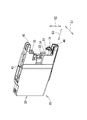
図1に示されるように、プリンタ10は、インクジェット記録方式に基づいて、記録用紙に対してインク滴を選択的に吐出することにより画像を記録するものである。プリンタ10は、インク供給装置100を備えている。インク供給装置100には、カートリッジ装着部110が設けられている。カートリッジ装着部110には、インクカートリッジ30が装着され得る。カートリッジ装着部110には、その一面が外部に開放された開口112が設けられている。インクカートリッジ30は、開口112を介してカートリッジ装着部110に挿入され、或いはカートリッジ装着部110から抜き出される。プリンタ10が、インクジェット記録装置に相当する。
[Overview of Printer 10]
As shown in FIG. 1, the printer 10 records an image by selectively ejecting ink droplets onto a recording sheet based on an ink jet recording method. The printer 10 includes an ink supply device 100. The ink supply device 100 is provided with a cartridge mounting portion 110. The ink cartridge 30 can be mounted on the cartridge mounting unit 110. The cartridge mounting portion 110 is provided with an opening 112 whose one surface is open to the outside. The ink cartridge 30 is inserted into or removed from the cartridge mounting part 110 through the opening 112. The printer 10 corresponds to an ink jet recording apparatus.

インクカートリッジ30には、プリンタ10で使用可能なインクが貯留されている。カートリッジ装着部110に装着された状態において、インクカートリッジ30と記録ヘッド21とがインクチューブ20で接続されている。記録ヘッド21にはサブタンク28が設けられている。サブタンク28は、インクチューブ20を通じて供給されるインクを一時的に貯留する。記録ヘッド21は、インクジェット記録方式によって、サブタンク28から供給されたインクをノズル29から選択的に吐出する。記録ヘッド21が記録部に相当する。   The ink cartridge 30 stores ink that can be used by the printer 10. The ink cartridge 30 and the recording head 21 are connected by the ink tube 20 in a state where the cartridge is mounted in the cartridge mounting unit 110. The recording head 21 is provided with a sub tank 28. The sub tank 28 temporarily stores the ink supplied through the ink tube 20. The recording head 21 selectively ejects the ink supplied from the sub tank 28 from the nozzles 29 by the ink jet recording method. The recording head 21 corresponds to a recording unit.

給紙トレイ15から給紙ローラ23によって搬送路24へ送給された記録用紙は、搬送ローラ対25によってプラテン26上へ搬送される。記録ヘッド21は、プラテン26上を通過する記録用紙に対してインクを選択的に吐出する。これにより、画像が記録用紙に記録される。プラテン26を通過した記録用紙は、排出ローラ対22によって、搬送路24の最下流側に設けられた排紙トレイ16に排出される。   The recording paper fed from the paper feed tray 15 to the transport path 24 by the paper feed roller 23 is transported onto the platen 26 by the transport roller pair 25. The recording head 21 selectively ejects ink onto a recording sheet that passes over the platen 26. Thereby, an image is recorded on the recording paper. The recording sheet that has passed through the platen 26 is discharged by a discharge roller pair 22 to a discharge tray 16 provided on the most downstream side of the transport path 24.

[インクカートリッジ30]
図2,3に示されるように、インクカートリッジ30はインクが貯留される容器である。インクカートリッジ30の内部に形成されている空間がインクを貯留するインク室36である。なお、本実施形態においては、インク室36に貯留されているインクは、水を主成分とする水性インクである。また、インク室36に貯留されているインクのインク室36の容積に対する割合は、大きい方が好ましい。具体的には、インク室36に貯留され、インク室36において高さ方向52の下側を占めるインクと、インク室36において高さ方向52の上側を占める空気との界面が、後述する残量検知部33よりも上側となることが好ましい。
[Ink cartridge 30]
As shown in FIGS. 2 and 3, the ink cartridge 30 is a container for storing ink. A space formed inside the ink cartridge 30 is an ink chamber 36 for storing ink. In the present embodiment, the ink stored in the ink chamber 36 is a water-based ink containing water as a main component. The ratio of the ink stored in the ink chamber 36 to the volume of the ink chamber 36 is preferably large. Specifically, an interface between the ink stored in the ink chamber 36 and occupying the lower side of the height direction 52 in the ink chamber 36 and the air occupying the upper side of the height direction 52 in the ink chamber 36 is a remaining amount described later. It is preferable to be above the detection unit 33.

インクカートリッジ30は、図2に示された起立状態、つまり、同図の下側の面を底面とし、同図の上側の面を上面として、カートリッジ装着部110に対して矢印50(図6参照)で示される方向(以下「挿入及び取出方向50」と称する。)に沿って挿抜される。すなわち、インクカートリッジ30は、挿入向き56(図6参照)に沿ってカートリッジ装着部110に挿入され、また、取出向き55(図6参照)に沿ってカートリッジ装着部110から抜き出される。インクカートリッジ30は、起立状態のままカートリッジ装着部110に挿抜される。インクカートリッジ30がカートリッジ装着部110に装着される向きが挿入向き56であり、抜き出される向きが取出向き55である。本実施形態においては、挿入向き56及び取出向き55は、水平方向に沿った向きである。起立状態における高さ方向52が、重力方向に相当する。   The ink cartridge 30 is in the standing state shown in FIG. 2, that is, the bottom surface is the bottom surface and the top surface is the top surface, and the arrow 50 (see FIG. 6) with respect to the cartridge mounting portion 110. ) (Hereinafter referred to as “insertion and removal direction 50”). That is, the ink cartridge 30 is inserted into the cartridge mounting portion 110 along the insertion direction 56 (see FIG. 6), and is extracted from the cartridge mounting portion 110 along the removal direction 55 (see FIG. 6). The ink cartridge 30 is inserted into and removed from the cartridge mounting portion 110 while standing. The direction in which the ink cartridge 30 is mounted in the cartridge mounting portion 110 is the insertion direction 56, and the direction in which the ink cartridge 30 is extracted is the extraction direction 55. In the present embodiment, the insertion direction 56 and the removal direction 55 are directions along the horizontal direction. The height direction 52 in the standing state corresponds to the direction of gravity.

インクカートリッジ30は、本体31とカバー32とを有する。インク室36を区画する本体31は、カバー32により覆われている。カバー32には、第1突起45及び第2突起46が設けられている。第1突起45は、カバー32の前壁34から奥行き方向53に沿ってインク室36から離れる向きに延びるように設けられている。第1突起45の幅(幅方向51に沿った寸法)は、前壁34の幅と同じである。第1突起45は、前壁34から挿入向き56へ突出されている。第1突起45の先端は、後述されるインク供給部37の先端に形成されているインク供給口71より挿入向き56の前側まで突出されている。この第1突起45は、前壁34の幅と同幅であるが、前壁34の幅より狭い幅の板状のものであってもよいし、必ずしも設けられていなくてもよい。本体31及びカバー32が筐体に相当する。   The ink cartridge 30 has a main body 31 and a cover 32. A main body 31 that partitions the ink chamber 36 is covered with a cover 32. The cover 32 is provided with a first protrusion 45 and a second protrusion 46. The first protrusion 45 is provided so as to extend from the front wall 34 of the cover 32 along the depth direction 53 in a direction away from the ink chamber 36. The width of the first protrusion 45 (the dimension along the width direction 51) is the same as the width of the front wall 34. The first protrusion 45 protrudes from the front wall 34 in the insertion direction 56. The front end of the first protrusion 45 protrudes from the ink supply port 71 formed at the front end of the ink supply unit 37 described later to the front side in the insertion direction 56. The first protrusion 45 has the same width as the width of the front wall 34, but may be a plate having a width narrower than the width of the front wall 34, or may not necessarily be provided. The main body 31 and the cover 32 correspond to a housing.

第2突起46は、カバー32の前壁34の下端に設けられている。したがって、第2突起46は、後述されるインク供給部37のさらに下方に配置されている。第2突起46の幅は、前壁34の幅と同じである。第2突起46は、前壁34から挿入向き56へ突出されている。第2突起46の先端は、インク供給部37の先端であるインク供給口71より挿入向き56の前側まで突出されている。第2突起46も、第1突起45と同様に、必ずしも設けられていなくてもよい。   The second protrusion 46 is provided at the lower end of the front wall 34 of the cover 32. Accordingly, the second protrusion 46 is disposed further below the ink supply unit 37 described later. The width of the second protrusion 46 is the same as the width of the front wall 34. The second protrusion 46 protrudes from the front wall 34 in the insertion direction 56. The tip of the second protrusion 46 protrudes from the ink supply port 71, which is the tip of the ink supply unit 37, to the front side in the insertion direction 56. Similarly to the first protrusion 45, the second protrusion 46 is not necessarily provided.

図2,3に示されるように、カバー32の内部には、略直方体形状の本体31が設けられている。本体31は、幅方向(左右方向)51に細く、高さ方向(上下方向)52と奥行き方向(前後方向)53が幅方向51よりも大きい扁平形状である。インクカートリッジ30がカートリッジ装着部110へ装着されるときに前方側となる本体31の壁が本体前壁40であり、後方側となる本体31の壁が本体後壁42である。本体前壁40と本体後壁42とは、奥行き方向53において対向している。また、本体前壁40及び本体後壁42とを接続し、かつ本体前壁40の上端から本体後壁42の上端に向けて延びる本体31の壁が本体上壁39であり、本体前壁40及び本体後壁42とを接続し、かつ本体前壁40の下端から本体後壁42の下端に向けて延びる本体31の壁が本体下壁41である。なお、挿入及び取出方向50は奥行き方向53と平行である。   As shown in FIGS. 2 and 3, a substantially rectangular parallelepiped main body 31 is provided inside the cover 32. The main body 31 is thin in the width direction (left-right direction) 51, and has a flat shape in which the height direction (up-down direction) 52 and the depth direction (front-rear direction) 53 are larger than the width direction 51. When the ink cartridge 30 is mounted on the cartridge mounting portion 110, the wall of the main body 31 on the front side is the main body front wall 40, and the wall of the main body 31 on the rear side is the main body rear wall 42. The main body front wall 40 and the main body rear wall 42 face each other in the depth direction 53. The wall of the main body 31 that connects the main body front wall 40 and the main body rear wall 42 and extends from the upper end of the main body front wall 40 toward the upper end of the main body rear wall 42 is a main body upper wall 39. The wall of the main body 31 that connects the main body rear wall 42 and extends from the lower end of the main body front wall 40 toward the lower end of the main body rear wall 42 is the main body lower wall 41. Note that the insertion and removal direction 50 is parallel to the depth direction 53.

本体31は、その内部にインク室36を有する。インク室36は、本体31と、本体31の両側に固着されるフィルム(不図示)により区画される空間である。インク室36内には、補強などを目的として複数のリブが設けられているが、インク室36は、後述される残量検知部33、インク流路72、大気流路77とインク及び空気の流通が可能な空間である。   The main body 31 has an ink chamber 36 therein. The ink chamber 36 is a space defined by the main body 31 and a film (not shown) fixed to both sides of the main body 31. A plurality of ribs are provided in the ink chamber 36 for the purpose of reinforcement or the like. The ink chamber 36 includes a remaining amount detection unit 33, an ink flow path 72, an atmospheric flow path 77, and an ink and air flow, which will be described later. It is a space that can be distributed.

図3に示されるように、本体31の本体前壁40における高さ方向52の中央付近には、残量検知部33が設けられている。残量検知部33は、幅方向51に細く、高さ方向52と奥行き方向53が幅方向51よりも大きい扁平形状である。残量検知部33は中空であり、インク室36とインクが流通可能に通じている。つまり、残量検知部33とインク室との間には隔壁が存在しない。   As shown in FIG. 3, a remaining amount detection unit 33 is provided near the center in the height direction 52 of the main body front wall 40 of the main body 31. The remaining amount detection unit 33 is thin in the width direction 51 and has a flat shape in which the height direction 52 and the depth direction 53 are larger than the width direction 51. The remaining amount detection unit 33 is hollow and communicates with the ink chamber 36 so that ink can flow. That is, there is no partition between the remaining amount detection unit 33 and the ink chamber.

残量検知部33の中空部分にはセンサーアーム60のインジケータ部62が挿入されている。センサーアーム60は、板状のアーム本体61の両端に、インジケータ部62及びフロート部63とがそれぞれ設けられたものである。センサアーム60は、インク室36において、幅方向51に沿って延びる支軸64により回動可能に支持されている。センサーアーム60は、インク室36に存在するインク量に対応して、インジケータ部62が残量検知部33の高さ方向52下側に位置する下位姿勢と、インジケータ部62が残量検知部33の高さ方向52上側に位置する上位姿勢に姿勢変化可能である。なお、図3では、インジケータ部62が下位姿勢であり、インク室36内にインクが所定量存在する状態が示されている。   An indicator 62 of the sensor arm 60 is inserted into the hollow portion of the remaining amount detector 33. The sensor arm 60 is provided with an indicator portion 62 and a float portion 63 on both ends of a plate-like arm main body 61, respectively. In the ink chamber 36, the sensor arm 60 is rotatably supported by a support shaft 64 extending along the width direction 51. The sensor arm 60 corresponds to the amount of ink present in the ink chamber 36, and the indicator unit 62 is positioned in the lower position in the height direction 52 of the remaining amount detection unit 33, and the indicator unit 62 is the remaining amount detection unit 33. The posture can be changed to a higher posture positioned on the upper side in the height direction 52. In FIG. 3, the indicator unit 62 is in a lower posture, and a state where a predetermined amount of ink exists in the ink chamber 36 is shown.

インクカートリッジ30がカートリッジ装着部110に装着された状態において、カートリッジ装着部110に設けられた光センサ114に対して、残量検知部33は、赤外光を所定量以上透過させる状態と、残量検知部33が赤外光を所定量未満に遮光又は減衰させる状態とに変化する。インジケータ部62が上位姿勢であれば残量検知部33は赤外光を透過させ、インジケータ部62が下位姿勢であれば、残量検知部33は赤外光を遮光又は減衰させる。この残量検知部33の透光状態に応じて、インク室36内のインク残量が所定量未満になったことが判定される。   In a state where the ink cartridge 30 is mounted in the cartridge mounting unit 110, the remaining amount detection unit 33 is configured to transmit a predetermined amount or more of infrared light with respect to the optical sensor 114 provided in the cartridge mounting unit 110. The amount detection unit 33 changes to a state in which infrared light is shielded or attenuated below a predetermined amount. If the indicator unit 62 is in the upper position, the remaining amount detection unit 33 transmits infrared light, and if the indicator unit 62 is in the lower position, the remaining amount detection unit 33 blocks or attenuates infrared light. It is determined that the remaining amount of ink in the ink chamber 36 has become less than a predetermined amount according to the light transmission state of the remaining amount detection unit 33.

図3に示されるように、本体31の本体前壁40における残量検知部33の上側に、大気連通部38が設けられている。大気連通部38は、円筒形状の外形をなしており、本体前壁40から挿入及び取出方向50に沿って外側へ突出している。この大気連通部38は、カバー32の開口35を通じて外部へ露出されている。大気連通部38の突出端には、中空円筒形状の弾性部材80が設けられている。弾性部材80には、大気連通口76が形成されている。この大気連通口76から大気連通部38の内部空間を通じて、挿入及び取出方向50に延びてインク室36に通ずる大気流路77が形成されている。大気連通口76は、大気連通バルブ75により開閉可能に構成されている。大気連通バルブ75は、コイルバネ78により大気連通口76側へ付勢されて、常時は、弾性部材80に密接して大気連通口76を閉じている。また、大気連通バルブ75の一部であるロッド79は、大気連通口76から外側へ突出されている。インクカートリッジ30がカートリッジ装着部110に装着されると、カートリッジ装着部110に設けられた大気接続部105の先端(図6参照)が、大気連通バルブ75のロッド79に当接して、コイルバネ78の付勢力に抗して大気連通バルブ75を弾性部材80から離反させる。これにより大気連通口76が開かれて、負圧に維持された状態のインク室36の気圧が外気圧となる。また、インクカートリッジ30がカートリッジ装着部110に装着されると、大気接続部105の先端が弾性部材80内に入り込み、弾性部材80の内周面が大気接続部105の外周面に密着する。すなわち、弾性部材80が弾性変形しつつ、大気接続部105の外周面に接触した状態となる。大気流路77が気体流路に相当する。   As shown in FIG. 3, an air communication unit 38 is provided above the remaining amount detection unit 33 in the main body front wall 40 of the main body 31. The atmosphere communicating portion 38 has a cylindrical outer shape, and protrudes outward along the insertion and extraction direction 50 from the main body front wall 40. The air communication part 38 is exposed to the outside through the opening 35 of the cover 32. A hollow cylindrical elastic member 80 is provided at the protruding end of the air communication portion 38. An air communication port 76 is formed in the elastic member 80. An atmospheric flow path 77 extending in the insertion and extraction direction 50 from the atmospheric communication port 76 through the internal space of the atmospheric communication portion 38 and communicating with the ink chamber 36 is formed. The air communication port 76 is configured to be opened and closed by an air communication valve 75. The atmosphere communication valve 75 is urged toward the atmosphere communication port 76 by a coil spring 78 and normally closes the atmosphere communication port 76 in close contact with the elastic member 80. Further, the rod 79 that is a part of the atmosphere communication valve 75 protrudes outward from the atmosphere communication port 76. When the ink cartridge 30 is mounted on the cartridge mounting portion 110, the tip (see FIG. 6) of the atmospheric connection portion 105 provided on the cartridge mounting portion 110 comes into contact with the rod 79 of the atmospheric communication valve 75, and the coil spring 78 The atmospheric communication valve 75 is separated from the elastic member 80 against the urging force. As a result, the air communication port 76 is opened, and the atmospheric pressure in the ink chamber 36 maintained at a negative pressure becomes the external atmospheric pressure. When the ink cartridge 30 is mounted on the cartridge mounting portion 110, the tip of the atmospheric connection portion 105 enters the elastic member 80, and the inner peripheral surface of the elastic member 80 is in close contact with the outer peripheral surface of the atmospheric connection portion 105. That is, the elastic member 80 is in a state of being in contact with the outer peripheral surface of the air connection portion 105 while being elastically deformed. The atmospheric flow path 77 corresponds to a gas flow path.

なお、大気連通口76は、必ずしも大気連通バルブ75によって開閉可能な構成に限定されず、例えば、大気連通口76が弾性フィルムやゴム栓などで閉塞されており、インクカートリッジ30がカートリッジ装着部110に装着されると、大気接続部105などが弾性フィルムやゴム栓を突き破ることにより大気連通口76が開かれる構成であってもよい。   The air communication port 76 is not necessarily limited to a configuration that can be opened and closed by the air communication valve 75. For example, the air communication port 76 is closed with an elastic film, a rubber plug, or the like, and the ink cartridge 30 is placed in the cartridge mounting portion 110. When the air connection portion is mounted, the air communication port 76 may be opened by breaking the elastic film or the rubber plug.

図3に示されるように、本体31の本体前壁40における高さ方向52の中央より下側に、インク供給部37が設けられている。インク供給部37は、円筒形状の外形をなしており、本体前壁40から挿入及び取出方向50に沿って外側へ突出している。このインク供給部37は、カバー32の外側へ露出されている。インク供給部37の突出端にはインク供給口71が形成されている。このインク供給口71からインク供給部37の内部空間を通じて、挿入及び取出方向50に延びてインク室36へ通ずるインク流路72が形成されている。インク供給口71は、インク供給バルブ70によって開閉可能に構成されている。インク供給バルブ70は、コイルバネ73によりインク供給口71側へ付勢されて、常時は、インク供給口71を閉じている。インクカートリッジ30がカートリッジ装着部110に装着されると、カートリッジ装着部110に設けられたインクニードル122(図5参照)が、インク供給口71に挿入されてインク供給バルブ70をコイルバネ73の付勢力に抗してインク供給口71から離反させる。これにより、インク供給口71が開かれて、インク流路72を通ってインク室36から、カートリッジ装着部110に設けられたインクニードル122へインクが流出される。   As shown in FIG. 3, an ink supply unit 37 is provided below the center in the height direction 52 of the main body front wall 40 of the main body 31. The ink supply unit 37 has a cylindrical outer shape, and protrudes outward along the insertion and extraction direction 50 from the main body front wall 40. The ink supply unit 37 is exposed to the outside of the cover 32. An ink supply port 71 is formed at the protruding end of the ink supply unit 37. An ink flow path 72 extending from the ink supply port 71 through the internal space of the ink supply unit 37 in the insertion and extraction direction 50 to the ink chamber 36 is formed. The ink supply port 71 is configured to be opened and closed by an ink supply valve 70. The ink supply valve 70 is urged toward the ink supply port 71 by the coil spring 73 and normally closes the ink supply port 71. When the ink cartridge 30 is mounted on the cartridge mounting section 110, the ink needle 122 (see FIG. 5) provided on the cartridge mounting section 110 is inserted into the ink supply port 71, and the ink supply valve 70 is biased by the coil spring 73. Against the ink supply port 71. As a result, the ink supply port 71 is opened, and ink flows out from the ink chamber 36 through the ink flow path 72 to the ink needle 122 provided in the cartridge mounting portion 110.

なお、インク供給口71は、必ずしもインク供給バルブ70によって開閉可能な構成に限定されず、例えば、インク供給口71が弾性フィルムやゴム栓などで閉塞されており、インクカートリッジ30がカートリッジ装着部110に装着されると、インクニードル122が弾性フィルムやゴム栓を突き破ることによりインク供給口71が開かれる構成であってもよい。   The ink supply port 71 is not necessarily limited to a configuration that can be opened and closed by the ink supply valve 70. For example, the ink supply port 71 is closed by an elastic film, a rubber plug, or the like, and the ink cartridge 30 is the cartridge mounting unit 110. The ink supply port 71 may be opened when the ink needle 122 breaks through an elastic film or a rubber plug.

本体31の本体上壁39における奥行き方向53の中央付近には、係合部43が形成されている。係合部43は、インクカートリッジ30の幅方向51及び高さ方向52に拡がる平面を有する突起である。係合部43は、カバー32には覆われておらず、外部へ露出されている。係合部43には、インクカートリッジ30がカートリッジ装着部110に装着された状態で、後述されるロックレバー145が係合する。この係合部43は、インクカートリッジ30を取出向き55に押し出させる付勢力を受けるものである。   An engaging portion 43 is formed in the vicinity of the center in the depth direction 53 of the main body upper wall 39 of the main body 31. The engaging portion 43 is a protrusion having a flat surface extending in the width direction 51 and the height direction 52 of the ink cartridge 30. The engaging portion 43 is not covered by the cover 32 and is exposed to the outside. A lock lever 145 (described later) is engaged with the engaging portion 43 in a state where the ink cartridge 30 is mounted on the cartridge mounting portion 110. The engaging portion 43 receives a biasing force that pushes the ink cartridge 30 in the removal direction 55.

[インク供給装置100]
図1に示されるように、インク供給装置100は、プリンタ10に設けられている。インク供給装置100は、プリンタ10が備える記録ヘッド21へインクを供給するものである。インク供給装置100は、インクカートリッジ30を装着可能なカートリッジ装着部110を備えている。なお、図1においては、カートリッジ装着部110にインクカートリッジ30が装着された状態が示されている。
[Ink supply apparatus 100]
As shown in FIG. 1, the ink supply device 100 is provided in the printer 10. The ink supply device 100 supplies ink to the recording head 21 provided in the printer 10. The ink supply device 100 includes a cartridge mounting unit 110 in which the ink cartridge 30 can be mounted. FIG. 1 shows a state where the ink cartridge 30 is mounted on the cartridge mounting portion 110.

[カートリッジ装着部110]
図4〜6に示されるように、カートリッジ装着部110の筐体を形成するケース101は、プリンタ10の正面側に開口112を有する。開口112を通じてケース101へインクカートリッジ30が挿抜される。ケース101には、シアン、マゼンタ、イエロー、ブラックの各色のインクに対応する4つのインクカートリッジ30が収容可能である。
[Cartridge mounting part 110]
As shown in FIGS. 4 to 6, the case 101 forming the casing of the cartridge mounting unit 110 has an opening 112 on the front side of the printer 10. The ink cartridge 30 is inserted into and removed from the case 101 through the opening 112. The case 101 can accommodate four ink cartridges 30 corresponding to cyan, magenta, yellow, and black inks.

ケース101には、内部空間を縦方向に長い4つの空間に仕切り分ける3つのプレート102が設けられている。このプレート102によって仕切り分けられた各空間それぞれにインクカートリッジ30が収容される。プレート102は、ケース101において開口112と反対側となる終面側(奥側)に設けられている。   The case 101 is provided with three plates 102 that partition the internal space into four spaces that are long in the vertical direction. The ink cartridge 30 is accommodated in each space partitioned by the plate 102. The plate 102 is provided on the end surface side (back side) opposite to the opening 112 in the case 101.

図5に示されるように、ケース101の終面の下部にインク接続部103が設けられている。インク接続部103は、終面において、ケース101に装着された各インクカートリッジ30のインク供給部37に対応する位置にそれぞれ配置されている。本実施形態では、ケース101に収容可能な4つのインクカートリッジ30に対応して4つのインク接続部103が設けられている。   As shown in FIG. 5, an ink connection portion 103 is provided at the lower portion of the end surface of the case 101. The ink connection portion 103 is disposed at a position corresponding to the ink supply portion 37 of each ink cartridge 30 attached to the case 101 on the final surface. In the present embodiment, four ink connection portions 103 are provided corresponding to the four ink cartridges 30 that can be accommodated in the case 101.

インク接続部103は、インクニードル122と、保持部121とを有する。インクニードル122は、管状の樹脂針からなる。インクニードル122は、ケース101の終面と表裏をなす外面側でインクチューブ20に接続されている。各インクニードル122から外面側へ引き出された各インクチューブ20は、ケース101の終面と対向する外側面において上方へ引き上げられたのち、プリンタ10の記録ヘッド21へインクを流通可能に延出されている。   The ink connection unit 103 includes an ink needle 122 and a holding unit 121. The ink needle 122 is made of a tubular resin needle. The ink needle 122 is connected to the ink tube 20 on the outer surface side that forms the front and back surfaces of the case 101. Each ink tube 20 pulled out from each ink needle 122 to the outer surface side is pulled upward on the outer surface facing the end surface of the case 101 and then extended to the recording head 21 of the printer 10 so that ink can flow. ing.

保持部121は、円筒状に形成されている。保持部121の中心にインクニードル122が配置されている。インクカートリッジ30がカートリッジ装着部110に装着されると、インク供給部37の外周面が保持部121の円筒の内周面にガイドされつつ、インク供給部37が保持部121の円筒の内側に挿入される。インク供給部37が保持部121へ挿入されると、インクニードル122がインク供給部37のインク供給口71に挿入される。これにより、インク室36に貯留されているインクが外部へ流出可能となる。インク室36から流出されたインクは、インクニードル122へ流入する。   The holding part 121 is formed in a cylindrical shape. An ink needle 122 is disposed at the center of the holding part 121. When the ink cartridge 30 is mounted on the cartridge mounting unit 110, the ink supply unit 37 is inserted inside the cylinder of the holding unit 121 while the outer peripheral surface of the ink supply unit 37 is guided by the inner peripheral surface of the cylinder of the holding unit 121. Is done. When the ink supply unit 37 is inserted into the holding unit 121, the ink needle 122 is inserted into the ink supply port 71 of the ink supply unit 37. As a result, the ink stored in the ink chamber 36 can flow out. The ink that has flowed out of the ink chamber 36 flows into the ink needle 122.

図6に示されるように、ケース101の終面において、インク接続部103より高さ方向52の上側にセンサユニット104が設けられている。センサユニット104は、基板113と、光センサ114とを備える。基板113に光センサ114が装着されることで、センサユニット104が構成されている。センサユニット104には、4つの光センサ114が設けられている。これら4つの光センサ114は、ケース101に収容可能な4つのインクカートリッジ30に対応している。4つの光センサ114は、各プレート102の間において、ケース101の幅方向に(幅方向51と一致する)に一列に配列されている。   As shown in FIG. 6, the sensor unit 104 is provided above the ink connecting portion 103 in the height direction 52 on the final surface of the case 101. The sensor unit 104 includes a substrate 113 and an optical sensor 114. The sensor unit 104 is configured by mounting the optical sensor 114 on the substrate 113. The sensor unit 104 is provided with four optical sensors 114. These four optical sensors 114 correspond to the four ink cartridges 30 that can be accommodated in the case 101. The four optical sensors 114 are arranged in a row in the width direction of the case 101 (matching the width direction 51) between the plates 102.

各光センサ114は、LEDなどの発光素子118と、フォトトランジスタなどの受光素子119とをそれぞれ有する。発光素子118及び受光素子119は、それぞれが筐体に囲まれている。光センサ114は、この筐体により形成される外形が馬蹄形である。発光素子118は、筐体から一方向へ光を照射可能である。受光素子は、筐体に対して一方向から照射された光を受光可能である。このような発光素子118と受光素子119とが、馬蹄形の筐体において所定の間隔を空けて対向配置されている。発光素子118と受光素子119との間の空間には、インクカートリッジ30の残量検知部33が進入可能である。光センサ114の光路に残量検知部33が進入すると、光センサ114は、残量検知部33による透光状態の変化を検知し得る。   Each optical sensor 114 includes a light emitting element 118 such as an LED and a light receiving element 119 such as a phototransistor. Each of the light emitting element 118 and the light receiving element 119 is surrounded by a casing. The outer shape of the optical sensor 114 formed by this housing is a horseshoe shape. The light emitting element 118 can emit light in one direction from the housing. The light receiving element can receive light emitted from one direction to the housing. Such a light emitting element 118 and a light receiving element 119 are arranged to face each other at a predetermined interval in a horseshoe-shaped housing. The remaining amount detection unit 33 of the ink cartridge 30 can enter the space between the light emitting element 118 and the light receiving element 119. When the remaining amount detector 33 enters the optical path of the optical sensor 114, the optical sensor 114 can detect a change in the light transmission state by the remaining amount detector 33.

図5に示されるように、ケース101の終面の上部に大気接続部105が設けられている。大気接続部105は、終面において、ケース101に装着された各インクカートリッジ30の大気連通部38に対応する位置にそれぞれ配置されている。本実施形態では、ケース101に収容可能な4つのインクカートリッジ30に対応して4つの大気接続部105が設けられている。   As shown in FIG. 5, an air connection portion 105 is provided on the upper end surface of the case 101. The atmospheric connection portion 105 is disposed at a position corresponding to the atmospheric communication portion 38 of each ink cartridge 30 attached to the case 101 on the final surface. In the present embodiment, four atmospheric connection portions 105 are provided corresponding to the four ink cartridges 30 that can be accommodated in the case 101.

大気接続部105は、ケース101の終面から開口112側へ向かって突出する中空円筒状に形成されている。大気接続部105の突出端には、開口106が形成されている。インクカートリッジ30がカートリッジ装着部110に装着されると、大気接続部105がカバー32の開口35へ進入して、大気接続部105の突出端が大気連通部38の弾性部材80内に入り込む。このとき、弾性部材80の内周面が大気接続部105の外周面に密着する。すなわち、弾性部材80が弾性変形しつつ、大気接続部105の外周面に接触した状態となる。これにより、大気接続部105の突出端により大気連通バルブ75のロッド79がコイルバネ78の付勢力に抗して押し込まれて、大気連通口76が開かれる。そして、大気接続部105の開口106から、大気連通口76、大気流路77を通じてインク室36に空気が流入する。なお、弾性部材80の内周面が大気接続部105の外周面に密着しているので、弾性部材80の内周面と大気接続部105の外周面との間を空気やインクが通過することが防止されている。   The air connection portion 105 is formed in a hollow cylindrical shape that protrudes from the end surface of the case 101 toward the opening 112 side. An opening 106 is formed at the protruding end of the air connection portion 105. When the ink cartridge 30 is mounted on the cartridge mounting portion 110, the atmospheric connection portion 105 enters the opening 35 of the cover 32, and the protruding end of the atmospheric connection portion 105 enters the elastic member 80 of the atmospheric communication portion 38. At this time, the inner peripheral surface of the elastic member 80 is in close contact with the outer peripheral surface of the air connection portion 105. That is, the elastic member 80 is in a state of being in contact with the outer peripheral surface of the air connection portion 105 while being elastically deformed. Thereby, the rod 79 of the atmospheric communication valve 75 is pushed against the urging force of the coil spring 78 by the protruding end of the atmospheric connection portion 105, and the atmospheric communication port 76 is opened. Then, air flows into the ink chamber 36 from the opening 106 of the atmosphere connection portion 105 through the atmosphere communication port 76 and the atmosphere channel 77. Since the inner peripheral surface of the elastic member 80 is in close contact with the outer peripheral surface of the atmospheric connection portion 105, air or ink passes between the inner peripheral surface of the elastic member 80 and the outer peripheral surface of the atmospheric connection portion 105. Is prevented.

図6に示されるように、スライド部材135は、カートリッジ装着部110の奥部の下端側に形成された空間130に配置されている。本実施形態では、ケース101に収容可能な4つのインクカートリッジ30に対応して4つのスライド部材135が設けられている。空間130は、カートリッジ装着部110の内部空間と連続している。スライド部材135は、空間130において挿入及び取出方向50に沿って延出された支持ロッド133によって挿入及び取出方向50に沿ってスライド可能に支持されている。スライド部材135は、概ね直方体の外形をなす。スライド部材135は、インクカートリッジ30の第2突起46の挿入経路に配置されており、第2突起46の先端と当接可能である。つまり、スライド部材135は、第2突起46の先端と挿入向き56に対向して設けられている。   As shown in FIG. 6, the slide member 135 is disposed in a space 130 formed on the lower end side of the back part of the cartridge mounting part 110. In the present embodiment, four slide members 135 are provided corresponding to the four ink cartridges 30 that can be accommodated in the case 101. The space 130 is continuous with the internal space of the cartridge mounting unit 110. The slide member 135 is slidably supported along the insertion / removal direction 50 by a support rod 133 that extends along the insertion / removal direction 50 in the space 130. The slide member 135 has a substantially rectangular parallelepiped outer shape. The slide member 135 is disposed in the insertion path of the second protrusion 46 of the ink cartridge 30 and can contact the tip of the second protrusion 46. That is, the slide member 135 is provided to face the tip end of the second protrusion 46 in the insertion direction 56.

空間130にはコイルバネ139が設けられている。コイルバネ139は、スライド部材135を開口112側、つまり、インクカートリッジ30がカートリッジ装着部110から抜き出される向きへ、つまり開口112へ向かって、インクカートリッジ30を弾性付勢するものである。コイルバネ139は、空間130において挿入及び取出方向50に沿って延出された支持ロッド133に外嵌されて、空間130の終端を画定している終壁131とスライド部材135との間に介在されている。コイルバネ139が自然長である場合、つまり、スライド部材135に外力が加えられていない状態では、スライド部材135は、開口112側の所定の位置に配置される。インクカートリッジ30がカートリッジ装着部110に挿入される過程で、インクカートリッジ30の第2突起46がスライド部材135に当接して、スライド部材135が空間130の終壁131側へ押圧される。これにより、コイルバネ139が収縮されるとともに、スライド部材135が終壁131側の位置へスライドされる。収縮したコイルバネ139は、スライド部材135を介してインクカートリッジ30を取出向き55へ付勢する。   A coil spring 139 is provided in the space 130. The coil spring 139 elastically biases the ink cartridge 30 toward the opening 112, that is, in a direction in which the ink cartridge 30 is extracted from the cartridge mounting portion 110, that is, toward the opening 112. The coil spring 139 is externally fitted to a support rod 133 that extends along the insertion and extraction direction 50 in the space 130, and is interposed between the end wall 131 that defines the end of the space 130 and the slide member 135. ing. When the coil spring 139 has a natural length, that is, when no external force is applied to the slide member 135, the slide member 135 is disposed at a predetermined position on the opening 112 side. In the process of inserting the ink cartridge 30 into the cartridge mounting portion 110, the second protrusion 46 of the ink cartridge 30 contacts the slide member 135, and the slide member 135 is pressed toward the end wall 131 of the space 130. As a result, the coil spring 139 is contracted and the slide member 135 is slid to the position on the end wall 131 side. The contracted coil spring 139 urges the ink cartridge 30 toward the ejection direction 55 via the slide member 135.

ケース101には、ロックレバー145が設けられている。ロックレバー145は、カートリッジ装着部110に装着されたインクカートリッジ30を、コイルバネ139の付勢力に抗して、装着状態に維持するためのものである。ロックレバー145は、ケース101の開口112の上側に設けられている。本実施形態では、ケース101に装着可能な4つのインクカートリッジ30に対応して4つのロックレバー145が設けられている。   The case 101 is provided with a lock lever 145. The lock lever 145 is for maintaining the ink cartridge 30 mounted on the cartridge mounting portion 110 in the mounted state against the urging force of the coil spring 139. The lock lever 145 is provided above the opening 112 of the case 101. In the present embodiment, four lock levers 145 are provided corresponding to the four ink cartridges 30 that can be attached to the case 101.

ロックレバー145は、全体がアーム状に形成されている。ロックレバー145の中央付近に支軸147が設けられている。この支軸147がケース101に支持されている。これにより、ケース101の開口112の上側においてロックレバー145が支軸147を中心に回動可能に支持されている。ロックレバー145は、大別すると、操作部149と、被係合部146とに大別される。操作部149は、ケース101の開口112から外側へ突出されている。操作部149は、ロックレバー145を回動させるための操作を受け付ける部分である。被係合部146は、ケース101の内部へ進入している。被係合部146は、インクカートリッジ30の係合部43と係合可能である。被係合部146が係合部43と係合することにより、コイルバネ139に付勢されているインクカートリッジ30が、ケース101に対して装着状態に維持される。被係合部146が係合部43と係合可能な位置となるロックレバー145の回動位置がロック位置と称され、被係合部146が係合部43と係合しない位置がアンロック位置と称される。   The entire lock lever 145 is formed in an arm shape. A support shaft 147 is provided near the center of the lock lever 145. The support shaft 147 is supported by the case 101. Accordingly, the lock lever 145 is supported on the upper side of the opening 112 of the case 101 so as to be rotatable about the support shaft 147. The lock lever 145 is roughly divided into an operation part 149 and an engaged part 146. The operation unit 149 protrudes outward from the opening 112 of the case 101. The operation unit 149 is a part that receives an operation for rotating the lock lever 145. The engaged portion 146 enters the inside of the case 101. The engaged portion 146 can be engaged with the engaging portion 43 of the ink cartridge 30. When the engaged portion 146 engages with the engaging portion 43, the ink cartridge 30 biased by the coil spring 139 is maintained in the mounted state with respect to the case 101. The rotation position of the lock lever 145 where the engaged portion 146 can engage with the engaging portion 43 is referred to as a lock position, and the position where the engaged portion 146 does not engage with the engaging portion 43 is unlocked. It is called a position.

ロックレバー145には、コイルバネ148が取り付けられている。コイルバネ148によって、ロックレバー145は、ロック位置側へ付勢されている。ロック位置のロックレバー145に対して、操作部149が高さ方向52下向きへ押し下げられると、ロックレバー145がロック位置からアンロック位置へ回動される。   A coil spring 148 is attached to the lock lever 145. The lock lever 145 is biased toward the lock position by the coil spring 148. When the operation unit 149 is pushed downward in the height direction 52 with respect to the lock lever 145 at the lock position, the lock lever 145 is rotated from the lock position to the unlock position.

図6に示されるように、大気接続部105の内部空間は空洞であり、空気が流通可能な部屋107が形成されている。部屋107は、大気接続部105の開口106から挿入及び取出方向50に沿って大気接続部105の基端側へ延びている。大気接続部105は、ケース101に装着された各インクカートリッジ30の大気連通部38に対応して4つ設けられているので、部屋107も相互に独立して4つが形成されている。   As shown in FIG. 6, the internal space of the atmosphere connection portion 105 is a cavity, and a room 107 through which air can flow is formed. The room 107 extends from the opening 106 of the atmospheric connection portion 105 to the proximal end side of the atmospheric connection portion 105 along the insertion and extraction direction 50. Since four atmosphere connection portions 105 are provided corresponding to the atmosphere communication portions 38 of the ink cartridges 30 attached to the case 101, four chambers 107 are also formed independently of each other.

図7に示されるように、部屋107は、ケース101の終面と表裏をなす外面側に、つまり開口106と反対側に開口109を有する。この開口109は、部屋107を区画する周壁126の縁によって形成されている。周壁126は、挿入及び取出方向50に沿って延出されている。   As shown in FIG. 7, the room 107 has an opening 109 on the outer surface that forms the front and back surfaces of the case 101, that is, on the side opposite to the opening 106. The opening 109 is formed by the edge of the peripheral wall 126 that partitions the room 107. The peripheral wall 126 extends along the insertion and removal direction 50.

部屋107には、挿入及び取出方向50に沿って延びる区画壁127が設けられている。区画壁127によって、部屋107は、上下方向の上側となる第1空間115と、下側となる第2空間116とに区画されている。第1空間115は、大気接続部105の開口106と連続して開口109へ延びる空間である。第2空間116は、大気接続部105の開口106より下側であり且つ第1空間115の下側に配置されており、大気接続部105の開口106とは直接に接続されていないが、開口109へ延びる空間である。第2空間116が空気溜まりに相当する。   The room 107 is provided with a partition wall 127 extending along the insertion and removal direction 50. The partition wall 127 divides the room 107 into a first space 115 that is an upper side in the vertical direction and a second space 116 that is a lower side. The first space 115 is a space that continues to the opening 106 of the atmosphere connection portion 105 and extends to the opening 109. The second space 116 is located below the opening 106 of the atmospheric connection portion 105 and below the first space 115, and is not directly connected to the opening 106 of the atmospheric connection portion 105. This is a space extending to 109. The second space 116 corresponds to an air pocket.

区画壁127には、上下方向に区画壁127を貫通する接続路128が形成されている。この接続路128によって、第1空間115と第2空間116とは、インク及び空気が相互に流通可能に接続されている。接続路128は、第2空間116において、開口109とは反対側となる終面129から開口109側へ離れた位置に形成されている。   A connection path 128 that penetrates the partition wall 127 in the vertical direction is formed in the partition wall 127. By this connection path 128, the first space 115 and the second space 116 are connected so that ink and air can flow through each other. The connection path 128 is formed in the second space 116 at a position away from the end surface 129 on the opposite side of the opening 109 toward the opening 109.

周壁126の縁により形成されている開口109は、半透膜124により封止されている。半透膜124は、微小な孔を有する多孔質膜であり、例えば、ポリテトラフルオロエチレン、ポリクロロトリフルオロエチレン、テトラフルオロエチレン−ヘキサフルオロプロピレン共重合体、テトラフルオロエチレン−パーフルオロアルキルビニルエーテル共重合体、テトラフルオロエチレン−エチレン共重合体などのフッ素樹脂からなる。   The opening 109 formed by the edge of the peripheral wall 126 is sealed with a semipermeable membrane 124. The semipermeable membrane 124 is a porous membrane having minute pores, and includes, for example, polytetrafluoroethylene, polychlorotrifluoroethylene, tetrafluoroethylene-hexafluoropropylene copolymer, tetrafluoroethylene-perfluoroalkyl vinyl ether copolymer. It consists of fluororesins, such as a polymer and a tetrafluoroethylene-ethylene copolymer.

半透膜124が開口109を封止しているので、開口109は液密に封止される。一方、半透膜124は、ガーレー数に応じた抵抗により空気を通過させる。単位時間当たりに開口109を通過可能な空気量(流量)は、半透膜124のガーレー数に依存し、また、開口109の大きさに対応する半透膜124の面積(半透膜124の有効面積)に比例する。したがって、同じ素材、つまりガーレー数が同じ半透膜124を用いる場合には、開口109の大きさに対応する半透膜124の面積(半透膜124の有効面積)を広くするほど、つまり半透膜124により封止される開口109を大きくするほど空気の流量が上がる。換言すると、半透膜124のガーレー数及び面積により、半透膜124の空気の通過度が決まる。   Since the semipermeable membrane 124 seals the opening 109, the opening 109 is liquid-tightly sealed. On the other hand, the semipermeable membrane 124 allows air to pass therethrough with a resistance corresponding to the Gurley number. The amount of air that can pass through the opening 109 per unit time (flow rate) depends on the Gurley number of the semipermeable membrane 124, and the area of the semipermeable membrane 124 (the size of the semipermeable membrane 124 corresponding to the size of the opening 109). Effective area). Therefore, when the same material, that is, the semipermeable membrane 124 having the same Gurley number is used, the larger the area of the semipermeable membrane 124 corresponding to the size of the opening 109 (the effective area of the semipermeable membrane 124), that is, the semipermeable membrane 124 is. The larger the opening 109 sealed by the permeable membrane 124, the higher the air flow rate. In other words, the air permeability of the semipermeable membrane 124 is determined by the Gurley number and area of the semipermeable membrane 124.

半透膜124は、溶着により周壁126及び区画壁127の縁に固着されている。周壁126及び区画壁127は、例えばポリスチレンやポリプロピレンのような合成樹脂により成型されている。この周壁126及び区画壁127の縁に半透膜124を接触させた状態で、熱や高周波を用いて半透膜124が周壁126及び区画壁127の縁に溶着されている。この溶着において、周壁126及び区画壁127の縁が第2空間116側に若干溶け出す。溶け出した樹脂は、半透膜124が第2空間116に面する領域125を覆っている。これにより、半透膜124の領域125は、液体及び気体が通過不能となっている。つまり、第2空間116には、接続路128以外にインク及び空気が流出入する経路がない。   The semipermeable membrane 124 is fixed to the edges of the peripheral wall 126 and the partition wall 127 by welding. The peripheral wall 126 and the partition wall 127 are formed of a synthetic resin such as polystyrene or polypropylene, for example. With the semipermeable membrane 124 in contact with the edges of the peripheral wall 126 and the partition wall 127, the semipermeable membrane 124 is welded to the edges of the peripheral wall 126 and the partition wall 127 using heat or high frequency. In this welding, the edges of the peripheral wall 126 and the partition wall 127 are slightly melted toward the second space 116 side. The melted resin covers the region 125 where the semipermeable membrane 124 faces the second space 116. Thereby, the area | region 125 of the semipermeable membrane 124 cannot pass a liquid and gas. That is, the second space 116 has no path for ink and air to flow in and out other than the connection path 128.

[インクカートリッジ30の装着動作]
以下、図6が参照されつつ、インクカートリッジ30がカートリッジ装着部110に装着される動作が説明される。
[Installation operation of ink cartridge 30]
Hereinafter, the operation of mounting the ink cartridge 30 to the cartridge mounting unit 110 will be described with reference to FIG.

図には示されていないが、カートリッジ装着部110の開口112は、プリンタ10の筐体に設けられた開閉可能なカバーによって閉じられている。インクカートリッジ30が装着されるときには、このカバーが開かれる。   Although not shown in the drawing, the opening 112 of the cartridge mounting unit 110 is closed by an openable / closable cover provided on the housing of the printer 10. When the ink cartridge 30 is mounted, this cover is opened.

図6に示されるように、インクカートリッジ30がカートリッジ装着部110に対して挿入向き56へ挿入される。インクカートリッジ30がカートリッジ装着部110に挿入されると、まず、カバー32の挿入向き56の先端に形成された挿入向き56前側へ傾斜する案内面が、ロックレバー145の被係合部146に当接する。更にインクカートリッジ30がカートリッジ装着部110へ挿入されると、ロックレバー145の被係合部146がカバー32に乗りあがる。これにより、ロックレバー145が反時計回りに回動して、図6に示されるように、ロック位置からアンロック位置へ移動する。   As shown in FIG. 6, the ink cartridge 30 is inserted in the insertion direction 56 with respect to the cartridge mounting portion 110. When the ink cartridge 30 is inserted into the cartridge mounting portion 110, first, the guide surface inclined toward the front of the insertion direction 56 formed at the tip of the insertion direction 56 of the cover 32 contacts the engaged portion 146 of the lock lever 145. Touch. Further, when the ink cartridge 30 is inserted into the cartridge mounting portion 110, the engaged portion 146 of the lock lever 145 rides on the cover 32. As a result, the lock lever 145 rotates counterclockwise and moves from the locked position to the unlocked position as shown in FIG.

また、インクカートリッジ30の第2突起46の先端がスライド部材135に当接する。このとき、スライド部材135は、コイルバネ139に付勢された、空間130における開口112側に位置されている。ユーザは、図6に示されている状態から、さらにインクカートリッジ30をカートリッジ装着部110に挿入するために、コイルバネ139の付勢力に抗して、カバー32の後壁側を押し込む。   In addition, the tip of the second protrusion 46 of the ink cartridge 30 contacts the slide member 135. At this time, the slide member 135 is positioned on the opening 112 side in the space 130 urged by the coil spring 139. The user pushes the rear wall side of the cover 32 against the urging force of the coil spring 139 in order to insert the ink cartridge 30 into the cartridge mounting portion 110 from the state shown in FIG.

インクカートリッジ30の係合部43がロックレバー145の被係合部146より挿入向き56の前側へ到達すると、ロックレバー145が図6における時計回りに回動して、アンロック位置からロック位置へ移動する。これにより、ロックレバー145の被係合部146とインクカートリッジ30の係合部43とが係合して、コイルバネ139の付勢力に抗して、インクカートリッジ30が装着位置に保持される。   When the engaging portion 43 of the ink cartridge 30 reaches the front side in the insertion direction 56 from the engaged portion 146 of the lock lever 145, the lock lever 145 rotates clockwise in FIG. 6 to move from the unlock position to the lock position. Moving. As a result, the engaged portion 146 of the lock lever 145 and the engaging portion 43 of the ink cartridge 30 are engaged, and the ink cartridge 30 is held at the mounting position against the urging force of the coil spring 139.

装着位置において、インクカートリッジ30のインク供給口71にはインクニードル122が挿入されており、このインクニードル122によりインク供給バルブ70が開位置へ移動される。したがって、インク室36からインク流路72、インクニードル122を通じてインクチューブ20へインクが流出可能となる。また、ケース101の終面に設けられた大気接続部105により、大気連通バルブ75が開放されて、インク室36内が大気圧となる。すなわち、半透膜124から、部屋107、開口106、大気連通口76、大気流路77を介して、インク室36に空気が流入する。また、残量検知部33は、光センサ114により検知可能な位置へ到達され、残量検知部33内におけるセンサーアーム60のインジケータ部62の位置が検知されることに基づいて、インク室36のインク残量が判定される。   In the mounting position, an ink needle 122 is inserted into the ink supply port 71 of the ink cartridge 30, and the ink supply valve 70 is moved to the open position by the ink needle 122. Therefore, ink can flow out from the ink chamber 36 to the ink tube 20 through the ink flow path 72 and the ink needle 122. In addition, the atmosphere communication valve 75 is opened by the atmosphere connection portion 105 provided on the end surface of the case 101, and the inside of the ink chamber 36 becomes atmospheric pressure. That is, air flows from the semipermeable membrane 124 into the ink chamber 36 through the chamber 107, the opening 106, the atmosphere communication port 76, and the atmosphere channel 77. The remaining amount detection unit 33 reaches a position that can be detected by the optical sensor 114, and the position of the indicator unit 62 of the sensor arm 60 in the remaining amount detection unit 33 is detected. The ink remaining amount is determined.

インク室36のインクが消費されると、大気連通部38からインク室36内へ、インクの消費量に対応した量の空気が流入する。大気連通部38は、大気接続部105の開口106、部屋107を介して半透膜124に通じているので、半透膜124における空気の通過度が確保されていれば、これら流路を通じてインク室36へ空気が流入し得る。   When the ink in the ink chamber 36 is consumed, an amount of air corresponding to the amount of ink consumed flows from the atmosphere communicating portion 38 into the ink chamber 36. Since the atmosphere communicating portion 38 communicates with the semipermeable membrane 124 through the opening 106 and the room 107 of the atmosphere connecting portion 105, if the air permeability in the semipermeable membrane 124 is ensured, the ink is passed through these channels. Air can flow into the chamber 36.

プリンタ10において紙詰まりの処理や、修理のための梱包、搬送において、カートリッジ装着部110にインクカートリッジ30が装着された状態で、プリンタ10が縦置きされたり天地が逆さにされたりすることが想定される。その結果、インクカートリッジ30の大気連通口76が下向きとなったり、インク供給部37より大気連通部38が下側となったりした姿勢にプリンタ10が保持されると、インク室36から大気流路77、大気連通口76を通じて、インクが、部屋107に流れ込むおそれがあるが、部屋107の開口109が半透膜124で封止されているので、開口109からインクが流出して、センサユニット104等の電子部品を汚すことが防止される。   It is assumed that the printer 10 is placed vertically or upside down in the state where the ink cartridge 30 is mounted on the cartridge mounting unit 110 in the case of paper jam handling, repair packing, and transport in the printer 10. Is done. As a result, when the printer 10 is held in such a posture that the atmosphere communication port 76 of the ink cartridge 30 faces downward or the atmosphere communication section 38 faces downward from the ink supply section 37, the atmosphere flow path from the ink chamber 36. 77, the ink may flow into the room 107 through the atmosphere communication port 76. However, since the opening 109 of the room 107 is sealed with the semipermeable membrane 124, the ink flows out from the opening 109, and the sensor unit 104. It is possible to prevent the electronic parts from being contaminated.

例えば、プリンタ10がインクカートリッジ30の大気連通口36が下向きとなる姿勢にされると、図8(A)に示されるように、大気接続部105の開口106が上を向く。なお、図8においてはインクカートリッジ30は省略されているので、大気連通口36は示されていない。インク室36から大気連通口36を通じて部屋107の第1空間115にインクが流れ込むと、最も下側にある半透膜124とインクが接触して、徐々にインクの界面が開口106へ向かって上がっていく。この過程において、インクの界面が区画壁127の接続路128まで到達すると、接続路128を通じて第2空間116へもインクが流れ込む。インクの界面が区画壁127の接続路128より上側になると、第2空間116の終面129側に空気が閉じこめられるので、第1空間115から第2空間116へはインクが流れ込むことはない。つまり、第2空間116が空気溜まりとして機能する。図8(A)に示された状態から、プリンタ10が通常の姿勢に戻されると、第2空間116が第1空間115より下側となるので、第2空間116に残存した空気が接続路128を通じて第1空間115へ進入する。そして、周壁126の内面に沿って空気が開口109側へ移動して半透膜124側に接触する。例えば、第1空間115の上部を区画している周壁126の内面が開口109に近くなるほど高くなるように傾斜している。半透膜124に空気が接触することにより、空気が接触した領域の半透膜124の空気の通過度が速やかに回復される。そして、空気が接触した領域の半透膜124を介して空気が部屋107に流入し始め、インクが大気接続部105の開口106を介してインク室36に戻り始める。一旦インクがインク室36に戻り始めれば、半透膜124の他の領域もインクと接触しなくなり、他の領域においても空気の通過度が回復される。   For example, when the printer 10 is in a posture in which the atmosphere communication port 36 of the ink cartridge 30 is directed downward, as shown in FIG. 8A, the opening 106 of the atmosphere connection portion 105 faces upward. In FIG. 8, since the ink cartridge 30 is omitted, the air communication port 36 is not shown. When ink flows from the ink chamber 36 into the first space 115 of the chamber 107 through the atmosphere communication port 36, the ink contacts the lowermost semipermeable membrane 124, and the ink interface gradually rises toward the opening 106. To go. In this process, when the ink interface reaches the connection path 128 of the partition wall 127, the ink flows into the second space 116 through the connection path 128. When the ink interface is above the connection path 128 of the partition wall 127, air is confined to the end surface 129 side of the second space 116, so that ink does not flow from the first space 115 into the second space 116. That is, the second space 116 functions as an air reservoir. When the printer 10 is returned to the normal posture from the state shown in FIG. 8A, the second space 116 becomes lower than the first space 115, so that the air remaining in the second space 116 is connected to the connection path. Enter the first space 115 through 128. Then, the air moves along the inner surface of the peripheral wall 126 toward the opening 109 and contacts the semipermeable membrane 124 side. For example, the inner surface of the peripheral wall 126 that defines the upper portion of the first space 115 is inclined so as to become higher as it is closer to the opening 109. When the air contacts the semipermeable membrane 124, the air permeability of the semipermeable membrane 124 in the area where the air contacts is quickly recovered. Then, the air begins to flow into the chamber 107 through the semipermeable membrane 124 in the area in contact with the air, and the ink begins to return to the ink chamber 36 through the opening 106 of the atmospheric connection portion 105. Once the ink begins to return to the ink chamber 36, the other areas of the semipermeable membrane 124 do not come into contact with the ink, and the degree of air passage is restored in the other areas.

また、例えば、プリンタ10がインクカートリッジ30の大気連通部38がインク供給部口37より下側となる姿勢にされると、図8(B)に示されるように、第2空間116が第1空間115より上側となる。大気連通口36を通じて部屋107の第1空間115にインクが流れ込むと、第1空間115において、徐々にインクの界面が区画壁127へ向かって上がっていく。インクの界面が第1空間115において開口106より上側となっても、インクの界面が区画壁127に到達するまでは、半透膜124が空気を通過させるので、第1空間115の空気は半透膜124を通じて外部へ排出され、開口106から更にインクが第1空間115へ流入する。そして、インクの界面が区画壁127の接続路128まで到達すると、第2空間116に空気が閉じこめられるので、開口106から第1空間115へインクが流れ込むことがない。前述されたように、第2空間116において半透膜124が面する領域は樹脂により覆われて空気が通過不能となっているので、第2空間116から空気が排出される経路がない。このようにして、第2空間116が空気溜まりとして機能する。図8(B)に示された状態から、プリンタ10が通常の姿勢に戻されると、第2空間116が第1空間115より下側となるので、第2空間116に残存した空気が接続路128を通じて第1空間115へ進入する。そして、周壁126の内面に沿って空気が開口109側へ移動して半透膜124側に接触する。例えば、第1空間115の上部を区画している周壁126の内面が開口109に近くなるほど高くなるように傾斜している。半透膜124に空気が接触することにより、空気が接触した領域の半透膜124の空気の通過度が速やかに回復される。そして、空気が接触した領域の半透膜124を介して空気が部屋107に流入し始め、インクが大気接続部105の開口106を介してインク室36に戻り始める。一旦インクがインク室36に戻り始めれば、半透膜124の他の領域もインクと接触しなくなり、他の領域においても空気の通過度が回復される。   Further, for example, when the printer 10 is in an attitude in which the air communication portion 38 of the ink cartridge 30 is located below the ink supply port 37, the second space 116 is the first space as shown in FIG. Above the space 115. When ink flows into the first space 115 of the room 107 through the atmosphere communication port 36, the ink interface gradually rises toward the partition wall 127 in the first space 115. Even if the ink interface is above the opening 106 in the first space 115, the semipermeable membrane 124 allows air to pass through until the ink interface reaches the partition wall 127. The ink is discharged to the outside through the permeable membrane 124, and ink further flows into the first space 115 from the opening 106. When the ink interface reaches the connection path 128 of the partition wall 127, air is confined in the second space 116, so that ink does not flow into the first space 115 from the opening 106. As described above, the region of the second space 116 facing the semipermeable membrane 124 is covered with resin so that air cannot pass therethrough, so there is no path through which air is discharged from the second space 116. In this way, the second space 116 functions as an air reservoir. When the printer 10 is returned to the normal posture from the state shown in FIG. 8B, the second space 116 becomes lower than the first space 115, so that the air remaining in the second space 116 is connected to the connection path. Enter the first space 115 through 128. Then, the air moves along the inner surface of the peripheral wall 126 toward the opening 109 and contacts the semipermeable membrane 124 side. For example, the inner surface of the peripheral wall 126 that defines the upper portion of the first space 115 is inclined so as to become higher as it is closer to the opening 109. When the air contacts the semipermeable membrane 124, the air permeability of the semipermeable membrane 124 in the area where the air contacts is quickly recovered. Then, the air begins to flow into the chamber 107 through the semipermeable membrane 124 in the area in contact with the air, and the ink begins to return to the ink chamber 36 through the opening 106 of the atmospheric connection portion 105. Once the ink begins to return to the ink chamber 36, the other areas of the semipermeable membrane 124 do not come into contact with the ink, and the degree of air passage is restored in the other areas.

[本実施形態の作用効果]
本実施形態によれば、半透膜124が設けられた部屋107に空気溜まりとしての第2空間116が設けられているので、プリンタ10が傾けられるなどして、インク室36から大気流路77を通じて部屋107へインクが流入しても、第2空間116に空気が残存する。そして、プリンタ10が通常の姿勢に戻されると、第2空間116に残存した空気が半透膜124に接触し、その空気が接触している半透膜124の領域の空気の通過度が速やかに回復される。これにより、半透膜124を通じてインクカートリッジ30のインク室36へ空気が流入するので、インク室36からインクが円滑に流出され、記録ヘッド21におけるインクの吐出不良が抑制される。
[Operational effects of this embodiment]
According to the present embodiment, since the second space 116 as an air reservoir is provided in the room 107 in which the semipermeable membrane 124 is provided, the printer 10 is tilted, for example, so that the air flow path 77 from the ink chamber 36. Even if ink flows into the room 107 through the air, air remains in the second space 116. When the printer 10 is returned to the normal posture, the air remaining in the second space 116 comes into contact with the semipermeable membrane 124, and the air passage rate in the region of the semipermeable membrane 124 with which the air is in contact is quickly. Will be recovered. As a result, air flows into the ink chamber 36 of the ink cartridge 30 through the semipermeable membrane 124, so that the ink flows out smoothly from the ink chamber 36, and ink ejection defects in the recording head 21 are suppressed.

[変形例]
前述された実施形態では、部屋107、開口109及び半透膜124が、カートリッジ装着部110に設けられた態様が示されているが、これらは、インクカートリッジ30に設けられてもよい。
[Modification]
In the above-described embodiment, the mode in which the chamber 107, the opening 109, and the semipermeable membrane 124 are provided in the cartridge mounting unit 110 is shown, but these may be provided in the ink cartridge 30.

具体的には、図9に示されるように、インクカートリッジ30の本体31の本体前壁40側に、大気流路77と大気連通口76を通じて接続されている部屋108が設けられる。この部屋108の周壁140により、開口141が本体前壁40に形成されている。開口141は、半透膜142により封止されている。部屋108は区画壁143により第1空間137と第2空間138とに区画されており、区画壁143に形成された接続路136によりインク及び空気が流通可能に接続されている。この接続路136は、第2空間138における開口141と反対側の終面144から離れて位置されている。また、周壁140及び区画壁143の縁に半透膜142が溶着されることによって溶け出した樹脂によって覆われることにより、半透膜142において第2空間138に面する領域は、空気が通過不能とされている。   Specifically, as shown in FIG. 9, a chamber 108 connected to the air flow path 77 and the air communication port 76 is provided on the main body front wall 40 side of the main body 31 of the ink cartridge 30. An opening 141 is formed in the front wall 40 of the main body by the peripheral wall 140 of the room 108. The opening 141 is sealed with a semipermeable membrane 142. The room 108 is partitioned into a first space 137 and a second space 138 by a partition wall 143, and ink and air are connected to each other through a connection path 136 formed in the partition wall 143. The connection path 136 is located away from the end surface 144 on the opposite side of the opening 141 in the second space 138. Further, the semipermeable membrane 142 is covered with the resin melted by the welding of the semipermeable membrane 142 to the edges of the peripheral wall 140 and the partition wall 143, so that air cannot pass through the region facing the second space 138 in the semipermeable membrane 142. It is said that.

前述された変形例によっても、半透膜142が設けられた部屋108に空気溜まりとしての第2空間138が設けられているので、プリンタ10が傾けられるなどして、インク室36から大気流路77を通じて部屋108へインクが流入しても、第2空間138に空気が残存する。そして、プリンタ10が通常の姿勢に戻されると、第2空間138に残存した空気が半透膜142に接触し、その空気が接触している半透膜142の領域の空気の通過度が速やかに回復される。これにより、半透膜142を通じてインクカートリッジ30のインク室36へ空気が流入するので、インク室36からインクが円滑に流出され、記録ヘッド21におけるインクの吐出不良が抑制される。   Also in the modified example described above, since the second space 138 as an air reservoir is provided in the room 108 in which the semipermeable membrane 142 is provided, the printer 10 is tilted and the air flow path from the ink chamber 36 to the atmosphere 108. Even if ink flows into the room 108 through 77, air remains in the second space 138. When the printer 10 is returned to the normal posture, the air remaining in the second space 138 comes into contact with the semipermeable membrane 142, and the air passage rate in the region of the semipermeable membrane 142 with which the air is in contact is quickly. Will be recovered. As a result, air flows into the ink chamber 36 of the ink cartridge 30 through the semipermeable membrane 142, so that the ink flows out smoothly from the ink chamber 36, and ink ejection defects in the recording head 21 are suppressed.

10・・・プリンタ(インクジェット記録装置)
21・・・記録ヘッド(記録部)
30・・・インクカートリッジ
31・・・本体(筐体)
36・・・インク室
37・・・インク供給部
77・・・大気流路
101・・・ケース
107,108・・・部屋
109,141・・・開口
110・・・カートリッジ装着部
115,137・・・第1空間
116,138・・・第2空間(空気溜まり)
124,142・・・半透膜
126,140・・・周壁
127,143・・・区画壁
128,136・・・接続路
131,144・・・終面
10 ... Printer (inkjet recording device)
21: Recording head (recording unit)
30 ... Ink cartridge 31 ... Main body (housing)
36... Ink chamber 37... Ink supply section 77... Air flow path 101... Case 107, 108. ..First space 116, 138 ... second space (air reservoir)
124, 142 ... semipermeable membranes 126, 140 ... peripheral walls 127, 143 ... partition walls 128, 136 ... connection paths 131, 144 ... end face

Claims (6)

内部にインクが貯留されるインク室を有する筐体、及び当該筐体に設けられており、上記インク室に貯留されたインクを外部へ流出させるインク供給部を有するインクカートリッジと、当該インクカートリッジが装着されるカートリッジ装着部と、を備え、当該カートリッジ装着に装着されたインクカートリッジから供給されるインクを記録部が選択的に吐出して画像記録を行うインクジェット記録装置であって、
上記インク室へ気体を流入可能な気体流路と、
上記気体流路と接続されており、上記気体流路との接続部とは異なる箇所において開口している部屋と、
上記部屋の開口を封止する半透膜と、
上記部屋に設けられ、上記気体流路からインクが流入したときに空気が残存する空気溜まりと、を具備しており
当該インクジェット記録装置が、上記インク供給部より上記気体流路が上側となる通常の姿勢において、上記空気溜まりに残存した空気が、インクが流入している上記部屋へ進入し、上記開口側へ移動して上記半透膜に接触するインクジェット記録装置。
A housing having an ink chamber in which ink is stored; an ink cartridge provided in the housing; and an ink cartridge having an ink supply section for discharging the ink stored in the ink chamber to the outside; and the ink cartridge An ink jet recording apparatus that performs image recording by selectively ejecting ink supplied from an ink cartridge attached to the cartridge mounting,
A gas flow path capable of flowing gas into the ink chamber;
A room that is connected to the gas flow path and is open at a location different from the connection with the gas flow path;
A semipermeable membrane that seals the opening of the room;
An air reservoir that is provided in the chamber and in which air remains when ink flows from the gas flow path;
When the ink jet recording apparatus is in a normal posture in which the gas flow path is on the upper side of the ink supply unit, the air remaining in the air pool enters the room where the ink flows and moves to the opening side. An ink jet recording apparatus in contact with the semipermeable membrane .
上記空気溜まりは、上記気体流路と上記部屋との接続部よりも下方に配置されている請求項1に記載のインクジェット記録装置。   The inkjet recording apparatus according to claim 1, wherein the air reservoir is disposed below a connection portion between the gas flow path and the room. 上記部屋を、上記気体流路と接続された第1空間と、上記空気溜まりとなる第2空間と、に区画する区画壁を更に有し、
上記第1空間と上記第2空間とは、接続路によりインク及び空気が流通可能に接続されており、
上記半透膜は、上記区画壁と接触し、かつ上記第1空間及び上記第2空間に面しており、上記第2空間に面する領域が、気体が通過不能とされたものである請求項1又は2に記載のインクジェット記録装置。
A partition wall that divides the room into a first space connected to the gas flow path and a second space serving as the air reservoir;
The first space and the second space are connected so that ink and air can flow through a connection path,
The semipermeable membrane is in contact with the partition wall and faces the first space and the second space, and a region facing the second space is configured such that gas cannot pass therethrough. Item 3. The ink jet recording apparatus according to Item 1 or 2.
上記接続路は、上記第2空間において、上記半透膜により区画されている面と反対側の終面から離れた位置において上記第2空間と接続されている請求項3に記載のインクジェット記録装置。   4. The inkjet recording apparatus according to claim 3, wherein the connection path is connected to the second space at a position away from the end surface on the opposite side of the surface partitioned by the semipermeable membrane in the second space. . 上記部屋の開口の縁を形成する周壁及び上記区画壁は樹脂により形成されており、
上記半透膜は、上記周壁の縁及び上記区画壁の縁に溶着されたものであって、当該溶着において上記周壁の縁及び上記区画壁の縁から溶け出した樹脂に覆われることより、上記領域が気体を通過不能とされたものである請求項3又は4に記載のインクジェット記録装置。
The peripheral wall forming the edge of the opening of the room and the partition wall are made of resin,
The semipermeable membrane is welded to the edge of the peripheral wall and the edge of the partition wall, and is covered with the resin melted from the edge of the peripheral wall and the edge of the partition wall in the welding, The ink jet recording apparatus according to claim 3 or 4, wherein the region is made incapable of passing gas.
上記部屋は、上記カートリッジ装着部に設けられている請求項1から5のいずれかに記載のインクジェット記録装置。   The inkjet recording apparatus according to claim 1, wherein the chamber is provided in the cartridge mounting portion.
JP2011073614A 2011-03-29 2011-03-29 Inkjet recording device Active JP5370403B2 (en)

Priority Applications (2)

Application Number Priority Date Filing Date Title
JP2011073614A JP5370403B2 (en) 2011-03-29 2011-03-29 Inkjet recording device
US13/346,344 US8550608B2 (en) 2011-03-29 2012-01-09 Ink cartridge and inkjet recording apparatus using the same

Applications Claiming Priority (1)

Application Number Priority Date Filing Date Title
JP2011073614A JP5370403B2 (en) 2011-03-29 2011-03-29 Inkjet recording device

Publications (2)

Publication Number Publication Date
JP2012206374A JP2012206374A (en) 2012-10-25
JP5370403B2 true JP5370403B2 (en) 2013-12-18

Family

ID=46926680

Family Applications (1)

Application Number Title Priority Date Filing Date
JP2011073614A Active JP5370403B2 (en) 2011-03-29 2011-03-29 Inkjet recording device

Country Status (2)

Country Link
US (1) US8550608B2 (en)
JP (1) JP5370403B2 (en)

Families Citing this family (9)

* Cited by examiner, † Cited by third party
Publication number Priority date Publication date Assignee Title
JP6079365B2 (en) * 2013-03-27 2017-02-15 ブラザー工業株式会社 Liquid supply device and liquid cartridge
JP6183107B2 (en) * 2013-09-27 2017-08-23 ブラザー工業株式会社 Liquid supply device
JP6187357B2 (en) 2014-03-31 2017-08-30 ブラザー工業株式会社 Liquid ejection device, liquid cartridge, and liquid ejection system
JP2016005886A (en) * 2014-05-30 2016-01-14 キヤノン株式会社 Liquid discharge head
JP6459673B2 (en) * 2014-07-25 2019-01-30 セイコーエプソン株式会社 printer
JP6915271B2 (en) * 2016-12-28 2021-08-04 ブラザー工業株式会社 Image recording device
JP7031182B2 (en) * 2017-09-08 2022-03-08 ブラザー工業株式会社 Inkjet recording device
JP7131027B2 (en) * 2018-03-30 2022-09-06 ブラザー工業株式会社 system
JP7099139B2 (en) * 2018-07-30 2022-07-12 ブラザー工業株式会社 Liquid cartridge

Family Cites Families (12)

* Cited by examiner, † Cited by third party
Publication number Priority date Publication date Assignee Title
JPS5656874A (en) * 1979-10-17 1981-05-19 Canon Inc Ink jet recording device
US4709249A (en) * 1984-06-21 1987-11-24 Canon Kabushiki Kaisha Ink jet recorder having ink container vent blocking means
CN1184076C (en) * 2000-02-16 2005-01-12 精工爱普生株式会社 Ink box and connecting assembly for ink-jet printer and ink-jet printer
JP3817727B2 (en) 2000-04-18 2006-09-06 セイコーエプソン株式会社 Inkjet recording device
US6846072B2 (en) * 2000-11-29 2005-01-25 Canon Kabushiki Kaisha Ink, ink-jet ink, ink-tank, ink-jet cartridge, ink supply device, method for introducing ink to ink tank and image recording device
JP2003266724A (en) * 2002-03-12 2003-09-24 Canon Inc Waste ink tank and inkjet recorder
US7040743B2 (en) * 2003-04-25 2006-05-09 Hewlett-Packard Development Company, L.P. Regulation of back pressure within an ink reservoir
US7159974B2 (en) * 2003-10-06 2007-01-09 Lexmark International, Inc. Semipermeable membrane for an ink reservoir and method of attaching the same
US7188937B2 (en) * 2004-01-29 2007-03-13 Hewlett-Packard Development Company, L.P. Printing-fluid venting assembly
US7429101B2 (en) * 2005-04-22 2008-09-30 Hewlett-Packard Development Company, L.P. Ink supply with ink/air separator assembly that is isolated from ink until time of use
JP2009132118A (en) * 2007-11-30 2009-06-18 Brother Ind Ltd Ink supplying device
JP5223740B2 (en) * 2009-03-16 2013-06-26 ブラザー工業株式会社 Liquid container

Also Published As

Publication number Publication date
US8550608B2 (en) 2013-10-08
US20120249692A1 (en) 2012-10-04
JP2012206374A (en) 2012-10-25

Similar Documents

Publication Publication Date Title
JP5370403B2 (en) Inkjet recording device
KR20230018510A (en) Printing apparatus
JP4803087B2 (en) Droplet discharge device
CN105984232B (en) Fluid cartridge
JP6950336B2 (en) Inkjet recording device
JP2012152998A (en) Liquid storage container mounted on liquid ejecting apparatus
JP2008230162A (en) Liquid droplet delivering apparatus and sub-tank for liquid droplet delivering apparatus
JP6098291B2 (en) Liquid cartridge
JP6187357B2 (en) Liquid ejection device, liquid cartridge, and liquid ejection system
JP6387790B2 (en) Cartridge and liquid consuming device
JP6098449B2 (en) Protective cap
JP5626065B2 (en) Inkjet recording device
JP5286760B2 (en) Ink cartridge, internal pressure adjustment method
JP6011309B2 (en) ink cartridge
JP5633453B2 (en) Fluid cartridge
JP2012206372A (en) Printing fluid cartridge
JP6020126B2 (en) ink cartridge
JP5732752B2 (en) Ink cartridge and ink supply device
JP7031372B2 (en) Liquid consuming device
JP6020125B2 (en) ink cartridge
JP6131592B2 (en) Printing fluid cartridge and method for manufacturing printing fluid cartridge
JP7077612B2 (en) Liquid drainer
JP3183798U (en) Ink supply device and ink cartridge
JP2012000854A (en) Ink supply device and ink cartridge
JP2018103564A (en) Liquid cartridge and image recording device

Legal Events

Date Code Title Description
A621 Written request for application examination

Free format text: JAPANESE INTERMEDIATE CODE: A621

Effective date: 20130315

A977 Report on retrieval

Free format text: JAPANESE INTERMEDIATE CODE: A971007

Effective date: 20130614

A131 Notification of reasons for refusal

Free format text: JAPANESE INTERMEDIATE CODE: A131

Effective date: 20130618

A521 Written amendment

Free format text: JAPANESE INTERMEDIATE CODE: A523

Effective date: 20130729

TRDD Decision of grant or rejection written
A01 Written decision to grant a patent or to grant a registration (utility model)

Free format text: JAPANESE INTERMEDIATE CODE: A01

Effective date: 20130820

A61 First payment of annual fees (during grant procedure)

Free format text: JAPANESE INTERMEDIATE CODE: A61

Effective date: 20130902

R150 Certificate of patent or registration of utility model

Ref document number: 5370403

Country of ref document: JP

Free format text: JAPANESE INTERMEDIATE CODE: R150

Free format text: JAPANESE INTERMEDIATE CODE: R150