US20120249692A1 - Ink cartridge and injet recording apparatus using the same - Google Patents
Ink cartridge and injet recording apparatus using the same Download PDFInfo
- Publication number
- US20120249692A1 US20120249692A1 US13/346,344 US201213346344A US2012249692A1 US 20120249692 A1 US20120249692 A1 US 20120249692A1 US 201213346344 A US201213346344 A US 201213346344A US 2012249692 A1 US2012249692 A1 US 2012249692A1
- Authority
- US
- United States
- Prior art keywords
- room
- ink
- air
- membrane
- wall
- Prior art date
- Legal status (The legal status is an assumption and is not a legal conclusion. Google has not performed a legal analysis and makes no representation as to the accuracy of the status listed.)
- Granted
Links
- 239000012528 membrane Substances 0.000 claims abstract description 103
- 238000007789 sealing Methods 0.000 claims abstract description 8
- 238000004891 communication Methods 0.000 claims description 34
- 238000000638 solvent extraction Methods 0.000 claims description 32
- 238000003466 welding Methods 0.000 claims description 6
- 229920005992 thermoplastic resin Polymers 0.000 claims description 5
- 229920002313 fluoropolymer Polymers 0.000 claims description 3
- 238000005192 partition Methods 0.000 claims description 3
- 239000007921 spray Substances 0.000 claims 2
- 230000002708 enhancing effect Effects 0.000 abstract description 2
- 238000003780 insertion Methods 0.000 description 22
- 230000037431 insertion Effects 0.000 description 22
- 230000002093 peripheral effect Effects 0.000 description 18
- 230000003287 optical effect Effects 0.000 description 7
- 230000004048 modification Effects 0.000 description 5
- 238000012986 modification Methods 0.000 description 5
- 230000035699 permeability Effects 0.000 description 5
- 229920005989 resin Polymers 0.000 description 4
- 239000011347 resin Substances 0.000 description 4
- 238000007334 copolymerization reaction Methods 0.000 description 3
- 239000007788 liquid Substances 0.000 description 2
- 238000000465 moulding Methods 0.000 description 2
- -1 polytetrafluoroethylene Polymers 0.000 description 2
- XLYOFNOQVPJJNP-UHFFFAOYSA-N water Substances O XLYOFNOQVPJJNP-UHFFFAOYSA-N 0.000 description 2
- PEVRKKOYEFPFMN-UHFFFAOYSA-N 1,1,2,3,3,3-hexafluoroprop-1-ene;1,1,2,2-tetrafluoroethene Chemical group FC(F)=C(F)F.FC(F)=C(F)C(F)(F)F PEVRKKOYEFPFMN-UHFFFAOYSA-N 0.000 description 1
- 239000004743 Polypropylene Substances 0.000 description 1
- 239000004793 Polystyrene Substances 0.000 description 1
- 230000005540 biological transmission Effects 0.000 description 1
- 238000001514 detection method Methods 0.000 description 1
- 239000012530 fluid Substances 0.000 description 1
- 239000006260 foam Substances 0.000 description 1
- 230000005484 gravity Effects 0.000 description 1
- 239000000463 material Substances 0.000 description 1
- 238000004806 packaging method and process Methods 0.000 description 1
- 230000000149 penetrating effect Effects 0.000 description 1
- 229920001155 polypropylene Polymers 0.000 description 1
- 229920002223 polystyrene Polymers 0.000 description 1
- 229920001343 polytetrafluoroethylene Polymers 0.000 description 1
- 239000004810 polytetrafluoroethylene Substances 0.000 description 1
- 239000011148 porous material Substances 0.000 description 1
- 230000002787 reinforcement Effects 0.000 description 1
- 239000012858 resilient material Substances 0.000 description 1
- 230000004044 response Effects 0.000 description 1
- 239000000758 substrate Substances 0.000 description 1
- 229920003002 synthetic resin Polymers 0.000 description 1
- 239000000057 synthetic resin Substances 0.000 description 1
Images


Classifications
-
- B—PERFORMING OPERATIONS; TRANSPORTING
- B41—PRINTING; LINING MACHINES; TYPEWRITERS; STAMPS
- B41J—TYPEWRITERS; SELECTIVE PRINTING MECHANISMS, i.e. MECHANISMS PRINTING OTHERWISE THAN FROM A FORME; CORRECTION OF TYPOGRAPHICAL ERRORS
- B41J2/00—Typewriters or selective printing mechanisms characterised by the printing or marking process for which they are designed
- B41J2/005—Typewriters or selective printing mechanisms characterised by the printing or marking process for which they are designed characterised by bringing liquid or particles selectively into contact with a printing material
- B41J2/01—Ink jet
- B41J2/17—Ink jet characterised by ink handling
- B41J2/175—Ink supply systems ; Circuit parts therefor
- B41J2/17503—Ink cartridges
- B41J2/17513—Inner structure
-
- B—PERFORMING OPERATIONS; TRANSPORTING
- B41—PRINTING; LINING MACHINES; TYPEWRITERS; STAMPS
- B41J—TYPEWRITERS; SELECTIVE PRINTING MECHANISMS, i.e. MECHANISMS PRINTING OTHERWISE THAN FROM A FORME; CORRECTION OF TYPOGRAPHICAL ERRORS
- B41J2/00—Typewriters or selective printing mechanisms characterised by the printing or marking process for which they are designed
- B41J2/005—Typewriters or selective printing mechanisms characterised by the printing or marking process for which they are designed characterised by bringing liquid or particles selectively into contact with a printing material
- B41J2/01—Ink jet
- B41J2/17—Ink jet characterised by ink handling
- B41J2/175—Ink supply systems ; Circuit parts therefor
- B41J2/17503—Ink cartridges
- B41J2/1752—Mounting within the printer
- B41J2/17523—Ink connection
-
- B—PERFORMING OPERATIONS; TRANSPORTING
- B41—PRINTING; LINING MACHINES; TYPEWRITERS; STAMPS
- B41J—TYPEWRITERS; SELECTIVE PRINTING MECHANISMS, i.e. MECHANISMS PRINTING OTHERWISE THAN FROM A FORME; CORRECTION OF TYPOGRAPHICAL ERRORS
- B41J2/00—Typewriters or selective printing mechanisms characterised by the printing or marking process for which they are designed
- B41J2/005—Typewriters or selective printing mechanisms characterised by the printing or marking process for which they are designed characterised by bringing liquid or particles selectively into contact with a printing material
- B41J2/01—Ink jet
- B41J2/17—Ink jet characterised by ink handling
- B41J2/175—Ink supply systems ; Circuit parts therefor
- B41J2/17503—Ink cartridges
- B41J2/17553—Outer structure
-
- B—PERFORMING OPERATIONS; TRANSPORTING
- B41—PRINTING; LINING MACHINES; TYPEWRITERS; STAMPS
- B41J—TYPEWRITERS; SELECTIVE PRINTING MECHANISMS, i.e. MECHANISMS PRINTING OTHERWISE THAN FROM A FORME; CORRECTION OF TYPOGRAPHICAL ERRORS
- B41J2/00—Typewriters or selective printing mechanisms characterised by the printing or marking process for which they are designed
- B41J2/005—Typewriters or selective printing mechanisms characterised by the printing or marking process for which they are designed characterised by bringing liquid or particles selectively into contact with a printing material
- B41J2/01—Ink jet
- B41J2/17—Ink jet characterised by ink handling
- B41J2/175—Ink supply systems ; Circuit parts therefor
- B41J2/17566—Ink level or ink residue control
Definitions
- the present invention relates to an ink cartridge and also to an inkjet recording apparatus provided with a cartridge mounting portion in which the ink cartridge is detachably mounted.
- Inkjet recording apparatuses have been extensively known and used in various fields.
- the inkjet recording apparatus has a recording head formed with a plurality of nozzles. Ink droplets are selectively ejected from the nozzles onto a recording paper to record images thereon.
- an ink cartridge is mounted on the inkjet recording apparatus to supply ink to the recording head.
- the ink cartridge has an ink chamber for storing ink therein.
- An air-hole is formed in the ink chamber to be fluidly communicable between the ink chamber and atmosphere. Air is introduced into the ink chamber from the air-hole to replace an amount ink consumed with a corresponding amount of air. Introduction of air into the ink chamber is essential to smoothly perform ink ejection.
- a porous or foam membrane is affixed to the air-hole.
- the membrane allows air to pass therethrough but interrupts ink from passing therethrough.
- a sub-tank is mounted in a carriage together with the recording head, and an air-hole and a membrane are provided in the sub-tank rather than the ink cartridge.
- ink cartridge having a slanted air communication channel connecting the ink chamber and the air-hole. If this type of ink cartridge or an inkjet recording apparatus in which such an ink cartridge is mounted is eventually inclined, ink stored in the ink chamber may move toward the air-hole and ink may be brought into contact the membrane sealing the air-hole. If it is the case, air is difficult to pass through the membrane, so that shortage of air introduction into the ink cartridge or into the sub-tank will occur and hence smooth ink ejection cannot be achieved or ink ejection failure may occur.
- the problem of ink ejection failure may not be resolved even if the ink cartridge or the sub-tank is returned to the normal posture from the inclined state if ink does not return to the ink chamber from the air-hole but remains in the clinging state to the membrane. More specifically, when the ink cartridge or the inkjet recording apparatus is inclined from the normal state, ink moving toward the air-hole expels air out of the ink cartridge through the membrane. When the ink cartridge or the inkjet recording apparatus is returned to the normal posture from the inclined state, a relevant amount of air needs to be smoothly introduced into the ink chamber attendant to the movement of the ink toward the ink chamber. However, this cannot be achieved if ink still clings to the membrane. Air does not pass through the ink-clinging portion of the membrane, so that ink does not move or is difficult to move toward the ink chamber. In consequence, ink remains in contact with the membrane, thereby making it difficult to recover the air permeability of the membrane.
- an ink cartridge including an ink chamber storing ink therein, an ink supply portion provided in the ink chamber, an air channel connected to the ink chamber and configured to introduce air into the ink chamber, a room wall defining an atmosphere communicable room connected to the air channel, the room wall being formed with an opening open to atmosphere; a membrane, and a characteristic recapture enhancement section.
- the membrane is provided for sealing the opening of the room wall.
- the membrane has a gas-permeable and liquid-impermeable characteristic.
- the characteristic recapture enhancement section is configured to enhance recapturement of the gas-permeable and liquid-impermeable characteristic of the membrane.
- the characteristic recapture enhancement section is operable when ink from the ink chamber clings to the membrane.
- an inkjet recording apparatus including a recording head, an ink cartridge, and a cartridge mounting portion in which the ink cartridge is detachably mounted.
- the ink cartridge has an ink chamber storing ink therein, an ink supply portion provided in the ink chamber and connected to the recording head, and an air channel connected to the ink chamber and configured to introduce air into the ink chamber.
- a room wall is provided that defines an atmosphere communicable room connected to the air channel.
- the room wall is formed with an opening open to atmosphere.
- a membrane seals the opening of the room wall.
- the membrane has a gas-permeable and liquid-impermeable characteristic.
- a characteristic recapture enhancement section is provided for enhancing recapturement of the gas-permeable and liquid-impermeable characteristic of the membrane, and is operable when ink from the ink chamber clings to the membrane.
- FIG. 1 is a schematic cross-sectional view showing an internal structure of an inkjet printer according to an embodiment of the invention
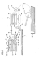
- FIG. 2 is a perspective view showing an outer appearance of an ink cartridge according to an embodiment of the invention.
- FIG. 3 is a vertical cross-sectional view showing an inner arrangement of the ink cartridge according to the embodiment of the invention.
- FIG. 4 is a perspective view showing a cartridge mounting portion provided in an inkjet printer
- FIG. 5 is a plan view of the cartridge mounting portion
- FIG. 6 is a cross-sectional view showing the ink cartridge mounted in the cartridge mounting portion
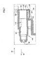
- FIG. 7 is an enlarged view showing a region VII encircled by two-dotted-chain line in FIG. 6 ;
- FIG. 8A is an enlarged cross-sectional view showing an orientation of an atmosphere-communicating nozzle when the inkjet printer is held vertically;
- FIG. 8B is an enlarged cross-sectional view showing an orientation of an atmosphere-communicating nozzle when the inkjet printer is held upside down;
- FIG. 9 is a partial enlarged view of an ink cartridge according to a modification of the embodiment.
- An inkjet printer 10 uses an inkjet recording system to record images by selectively ejecting ink droplets onto a recording paper.
- the inkjet printer 10 includes an ink supply device 100 .
- a cartridge mounting portion 110 is provided in the ink supply device 100 .
- An ink cartridge 30 can be mounted in the cartridge mounting portion 110 .
- An opening 112 is formed in one side surface of the cartridge mounting portion 110 .
- the ink cartridge 30 is inserted into or removed from the cartridge mounting portion 110 through the opening 112 .
- the structure of the inkjet printer 10 shown in FIG. 1 is one example of an inkjet recording apparatus of the present invention.
- the ink cartridge 30 stores ink that can be used by the inkjet printer 10 . While the ink cartridge 30 is mounted in the cartridge mounting portion 110 , the ink cartridge 30 is connected to a recording head 21 by an ink tube 20 .
- the recording head 21 is provided with a sub-tank 28 .
- the sub-tank 28 temporarily stores ink supplied from the ink cartridge 30 via the ink tube 20 .
- the recording head 21 selectively ejects ink supplied from the sub-tank 28 through nozzles 29 in response to image data.
- the inkjet printer 10 also includes a paper tray 15 accommodating sheets of recording paper and a feeding roller 23 for feeding sheets of paper from the paper tray 15 .
- the feeding roller 23 feeds the sheets of paper into a conveying path 24 .
- a pair of conveying rollers 25 conveys the sheets of paper along the conveying path 24 over a platen 26 .
- the recording head 21 selectively ejects ink droplets onto the recording paper as the paper passes over the platen 26 , thereby recording an image on the paper.
- a pair of discharge rollers 22 discharges the sheet of paper into a discharge tray 16 provided on the downstream end of the conveying path 24 .
- the ink supply device 100 is provided in the inkjet printer 10 .
- the ink supply device 100 functions to supply ink to the ink tube 20 provided in the inkjet printer 10 .
- the ink supply device 100 includes the cartridge mounting portion 110 in which the ink cartridge 30 can be detachably mounted.
- FIG. 1 shows the cartridge mounting portion 110 in which the ink cartridge 30 is mounted.
- the outer appearance of the ink cartridge 30 is show in FIG. 2
- the inner arrangement of the ink cartridge 30 is shown in FIG. 3
- the ink cartridge 30 is a vessel for storing ink therein.
- used is water soluble ink containing water as a major component.
- a space formed inside the ink cartridge 30 is an ink chamber 36 in which ink is stored. It is desirable that a maximum amount of ink capable of storing in the ink chamber 36 be as large as a volume of the ink chamber 36 . Specifically, it is desirable that in the ink full state, the boundary between ink and air in the ink chamber 30 be upper than the position of a residual ink amount detector 33 to be described later.
- FIG. 2 An upstanding state ink cartridge 30 is shown in FIG. 2 and this state will be referred to as a normal posture of the ink cartridge 30 . Therefore, one side surface of the ink cartridge 30 is a bottom and another opposing side surface thereof is a top. In use, the ink cartridge 30 needs to be inserted into the cartridge mounting portion 110 of the inkjet printer 10 .
- the inkjet printer 10 is generally elongated in horizontal direction when placed in the normal posture. When the ink cartridge becomes empty with no ink remaining therein, the ink cartridge 30 is removed from the cartridge mounting portion 110 for replacement with a new one. Normally, the ink cartridge 30 is removed from and inserted into the cartridge mounting portion 110 while maintaining the normal posture.
- carrier insertion direction 56 The direction in which the ink cartridge 30 is inserted into the cartridge mounting portion 110 is indicated by an arrow 56 and will hereinafter be referred to as “cartridge insertion direction 56 ”. Also, the direction in which the ink cartridge 30 is removed from the cartridge mounting portion 110 is indicated by an arrow 55 and will hereinafter be referred to as “cartridge removing direction 55 ”.
- the ink cartridge 30 is inserted into the cartridge mounting portion 110 by moving it in the cartridge insertion direction 56 and removed from the cartridge mounting portion 110 by pulling it out in the cartridge removing direction 55 as shown in FIG. 6 . Insertion and removal of the ink cartridge 30 are performed while maintaining the upstanding or normal posture of the ink cartridge 30 as shown in FIG. 2 .
- the cartridge removing direction 55 and cartridge insertion direction 56 are on a horizontal plane. That is, the insertion and removal of the ink cartridge 30 are performed by moving the ink cartridge 30 in a horizontal direction.
- the height direction 52 of the ink cartridge 30 is in coincidence with the direction of gravity.
- the ink cartridge 30 includes a main unit 31 and a cover 32 .
- An ink chamber 36 is formed in the internal space of the ink cartridge 30 for storing ink therein.
- the main unit 31 defines the ink chamber 36 and is covered with the cover 32 .
- the cover 32 is formed with a first arm (or interface) 45 and a second arm (or interface) 46 to be in parallel with each other.
- the first arm 45 projects from the front wall 34 in the cartridge insertion direction 56 .
- the widthwise thickness, i.e., the thickness in the widthwise direction 51 , of the first arm 45 is the same as the widthwise thickness of the front wall 34 .
- the first arm 34 extends in the cartridge insertion direction 56 to a horizontal position exceeding the ink supply port 71 formed at the end of an ink supply portion 37 .
- the widthwise thickness of the first arm 45 is the same as that of the front wall, the first arm 45 may be of a plate-shape with a widthwise thickness smaller than that of the front wall 34 .
- the first arm 45 is not absolutely necessary, so it can be dispensed with.
- the second arm 46 projects from the lower end of the front wall 34 of the cover 32 and extends in the cartridge insertion direction 56 to a position further than the ink supply portion 37 . Therefore, when the ink cartridge 30 is fully and completely inserted into the cartridge mounting portion 110 , the leading edge of the second arm 46 is brought into a position ahead of the ink supply portion 37 .
- the widthwise thickness of the second arm 46 is the same as that of the front wall 34 . Similar to the first arm 45 , the second arm 46 may not be provided.
- the main unit 31 of a substantially parallelepiped is provided inside the cover 31 .
- the main unit 31 is generally of a flat shape having a thin widthwise thickness and long vertical (in the height direction) and horizontal lengths relative to the widthwise thickness.
- the main unit 31 has a front wall 40 , a rear wall 42 , an upper wall 39 , and a lower wall 41 which are integrally formed as one unit.
- the front wall 40 and the rear wall 42 are spaced apart and opposes in the cartridge insertion/removing directions 56 , 55 .
- the front wall 40 and rear wall 42 are bridged by the upper wall 39 extending between the respective upper portions of the front wall 40 and the rear wall 42 .
- the front wall 40 and rear wall 42 are also bridged by the lower wall 41 extending between the respective lower portions of the front wall 40 and the rear wall 42 . Insertion of the ink cartridge 30 into the cartridge mounting portion 110 is performed by directing the front wall 40 of the cartridge 30 toward the cartridge mounting portion 110 .
- the ink chamber 36 is formed inside the main unit 31 .
- the ink chamber 36 is a space defined by the main unit 31 and films (not shown) attached to both sides of the main unit 31 .
- a plurality of ribs is provided in the ink chamber 36 for reinforcement purpose.
- the ink chamber 36 is fluidly communicable with the residual ink amount detector 33 , ink channel 72 , and air channel 77 .
- ink and air are communicable between the ink chamber 36 and its associated residual ink amount detector 33 , ink channel 72 , and air channel 77 .
- the residual ink amount detector 33 is provided at the vertical center area of the front wall 40 of the main unit 31 .
- the residual ink amount detector 33 is a flat shaped hollow member.
- the widthwise length of the ink amount detector 33 is much smaller than the lengths in the height direction 52 and also in the cartridge removing direction 55 (depthwise direction).
- the residual ink amount detector 33 is fluidly communicable with the ink chamber 36 . This means that no partitioning walls exist between the residual ink amount detector 33 and the ink chamber 36 .
- a sensor arm 60 is disposed in the ink chamber 36 and rotatably supported by a support shaft 64 extends in the widthwise direction 51 .
- the sensor arm 60 is an 5-shaped plate member and has an indicator portion 62 at one end thereof and a float portion 63 at another end thereof.
- the indicator portion 62 is accommodated in the internal space of the residual ink amount detector 33 .
- the sensor arm 60 takes an angular position depending upon an amount of ink remaining in the ink chamber 36 . Angular movements of the sensor arm 60 move the indicator portion 62 in the height direction 52 of the residual ink amount detector 33 .
- the indicator portion 62 is brought to the uppermost position of the residual ink amount detector 33 when the ink in the ink chamber 36 is empty or near-empty whereas the indicator portion 62 is brought to the lowermost position of the residual ink amount detector 33 when the ink in the ink chamber 36 is full.
- the indicator portion 62 is movable between the uppermost and lowermost positions and can indicate the amount of ink remaining in the ink chamber 36 by the vertical position of the indicator portion 62 in the residual ink amount detector 33 .
- FIG. 3 shows that the indicator portion 62 is held in the lowermost position, indicating that the ink chamber 36 is full of ink.
- an air hole 38 is formed in the front wall 40 of the main unit 31 at a position above the residual ink amount detector 33 .
- the air hole 38 is formed in a cylindrically elongated portion projecting frontwardly from the front wall 40 .
- the end face of air hole 38 is exposed outside through an opening 35 formed in the cover 32 .
- a sleeve 80 made from a resilient material is secured to the end face of the air hole 38 .
- An air communication port 76 is formed inside the sleeve 80 , which is fluidly connected to the air hole 38 .
- An air channel 77 is formed between the air-communication port 76 and the ink chamber 36 .
- the air channel 77 extends horizontally.
- the air-communication port 76 is capable of being open and closed by means of an air communication valve 75 .
- a coil spring 78 is provided to urge the air-communication valve 75 toward the air-communication port 76 . Due to the urging force of the coil spring 78 , the air-communication valve 75 is normally in intimate contact with the sleeve 80 , thereby closing the air-communication port 76 .
- the air communication valve 75 has a rod portion 75 projecting in the cartridge insertion direction 56 .
- the tip end of an air channel joint 105 provided in the cartridge mounting portion 110 is brought into abutment with the rod portion 79 of the air communication valve 75 , causing the air communication valve 75 to separate from the sleeve 80 against the urging force of the coil spring 78 .
- the negative pressure in the ink chamber 36 is brought to atmospheric pressure as a result of opening of the air communication hole 56 .
- the tip end of the air channel joint 105 is inserted into the inner space of the sleeve 80 and the inner peripheral surface of the sleeve 80 is brought into intimate contact with the outer peripheral surface of the air channel joint 105 .
- resilient deformation of the sleeve 80 allows the air channel joint 105 to fit into the sleeve 80 .
- the open/closure of the air-communication port 76 may not necessarily be performed by the air communication valve 75 . Instead, opening of the air-communication port 76 may be performed by sticking the air channel joint 105 into a resilient film or rubber cock sealing the air-communication port 76 when the ink cartridge 30 is mounted in the cartridge mounting portion 110 .
- an ink supply portion 37 is provided at the lower position on the front wall 40 of the main unit 31 .
- the ink supply portion 37 is cylindrical and projects horizontally outwardly from the front wall 40 .
- the ink supply portion 37 is exposed outside of the cover 32 .
- the ink supply port 71 is formed at the tip end of the ink supply portion 37 .
- the ink channel 72 is formed between the ink supply port 71 and the ink chamber 36 through the inner space of the ink supply portion 37 .
- the ink channel 72 extends horizontally.
- the ink supply port 71 is configured to be opened or closed by the ink supply valve 70 .
- the ink supply valve 70 is urged toward the ink supply port 71 by a coil spring 73 to thereby normally close the ink supply port 71 .
- an ink needle 122 (see FIG. 5 ) is inserted into the ink supply port 71 .
- the ink needle 122 separates the ink supply valve 70 from the ink supply port 71 against the urging force of the coil spring 73 .
- the ink supply port 71 is opened, thereby allowing ink in the ink chamber 36 to flow in the ink needle 122 provided in the cartridge mounting portion 110 through the ink channel 72 .
- the open/closure of the ink supply port 71 may not necessarily be performed by the ink supply valve 70 . Instead, a resilient film or rubber cock may be employed to seal the ink supply port 71 . In such cases, opening of the ink supply port 71 may be implemented by sticking the ink needle 22 into the resilient film or rubber cock when the ink cartridge 30 is mounted in the cartridge mounting portion 110 .
- an engagement portion 43 is formed in the upper wall 39 at a position near the center in the depthwise direction.
- the engagement portion 43 is provided for engaging a lock lever 145 (to be described later).
- the engagement portion 43 is urged in the cartridge removing direction 55 when the engagement portion 43 is brought into engagement with the lock lever 145 .
- the engagement portion 43 is an arm having vertical surfaces, a flat top surface, and a slanted surface. The engagement portion 43 is not covered by the cover 32 but exposed to outside of the cover 32 .
- a casing 101 for housing the cartridge mounting portion 110 therein is formed with an opening 112 in the front side of the printer 10 . Through the opening 112 , the ink cartridge 30 is inserted into and removed from the casing 101 .
- the casing 101 accommodates four ink cartridges 30 storing cyan, magenta, yellow and black ink.
- Three partitioning plates 102 are installed in the inner space of the casing 101 at a depth side from the opening 112 of the casing 101 .
- the partitioning plates 102 are provided for partitioning the inner space of the casing 101 into four rooms.
- the above-mentioned four ink cartridges are individually accommodated in the four rooms of the casing 101 .
- ink joint portions 103 are provided in association with the four ink cartridges 30 accommodated in the casing 101 at the lower portion on the peripheral surface of the casing 101 .
- the ink joint portions 103 are arranged at positions corresponding to the positions of the ink supply portions 37 of the ink cartridges 30 .
- Each ink joint portion 103 includes an ink needle 122 and a holding portion 121 .
- the ink needle 122 is a tubular shape and made from resin.
- the ink needle 122 is connected to an ink tube 20 at an outer surface of the casing 101 .
- the ink tube 20 extends upward on the outer surface of the casing 101 and then further extends and connected to the recording head 21 of the printer 10 .
- the holding portion 121 is of a cylindrical shape.
- the ink needle 122 is disposed at the center of the holding portion 121 .
- the ink supply portion 37 is inserted into the holding portion 121 while the outer peripheral surface of the ink supply portion 37 is guided by the inner peripheral surface of the holding portion 121 when the ink cartridge 30 is mounted in the cartridge mounting portion 110 . Insertion of the ink supply portion 37 into the holding portion 121 results in insertion of the ink needle 122 into the ink supply port 71 , thereby allowing ink stored in the ink chamber 36 to flow into the ink needle 122 .
- a sensor unit 104 is disposed on the peripheral surface of the casing 101 at a position above the ink joint portion 103 .
- the sensor unit 104 includes a substrate 113 and four optical sensors 114 mounted thereon.
- the four optical sensors 114 are provided corresponding to the four ink cartridges 30 .
- the optical sensors 114 are aligned in the widthwise direction of the casing 101 and each optical sensor is disposed in each room partitioned by the partitioning plates 102 .
- Each optical sensor 114 includes a light emitting element 118 , such as LED, and a light receiving element 119 , such as photo-transistor.
- the light emitting element 118 and the light receiving element 119 are surrounded by a horseshoe shaped housing.
- the light emitting element 118 is disposed to emit light in a selected direction
- the light receiving element 119 is disposed to receive the light from the light emitting element 118 .
- the light emitting element 118 and the light receiving clement 119 are disposed in spaced-apart and in confronting relation within the horseshoe shaped housing.
- the residual ink amount detector 33 provided in the ink cartridge 30 is capable of entering into the space between the light emitting element 118 and the light receiving element 119 . Entry of the residual ink amount detector 33 into the light path of the optical sensor 114 changes light transmission from the light emitting element 118 to the light receiving element 119 .
- the residual ink amount detector 33 is either in a first state or a second state when the ink cartridge 30 is inserted into the cartridge mounting portion 110 .
- the first state the residual ink amount detector 33 allows a predetermined amount of light to pass therethrough whereas in the second state, the residual ink amount detector 33 interrupts or attenuates the light so that the light receiving element 119 receives less than the predetermined amount of light.
- An infrared ray emitting diode may be used as a light emitting element.
- air channel joints 105 are provided at the upper position on the peripheral surface of the casing 101 .
- the air channel joints 105 are disposed in positions corresponding to the air holes 38 of the ink cartridges 30 .
- four air channel joints 105 are provided corresponding to the four ink cartridges 30 to be accommodated in the casing 101 .
- the air channel joint 105 is substantially of a hollow cylindrical shape that projects from the front wall of the casing 101 toward the opening 112 .
- a through-hole 106 is formed at the projected tip end of the air channel joint 105 .
- the air channel joint 105 advances into the opening 35 of the cover 32 and the projected end of the air channel joint 105 is inserted into the resilient block 80 disposed in the air hole 38 .
- the outer surface of the air channel joint 105 is brought into intimate contact with the inner surface of the resilient block 80 .
- the rod 79 of the atmosphere-communication valve 75 is pushed into the resilient block 80 against the urging force of the coil spring 78 by the aid of the projected end of the air channel joint 105 , resulting in opening of the air-communication port 76 .
- air is introduced into the ink chamber 36 from the through-hole 106 of the air channel joint 105 via the air-communication port 76 and the air channel 77 . Since the inner surface of the resilient block 80 is in intimate contact with the outer surface of the air channel joint 105 , air and/or ink are prevented from being leaked from the contacted portion.
- the slide member 135 is provided in a space 130 formed in the depth side lower portion of the cartridge mounting portion 110 .
- four slide members 135 are provided corresponding to the four ink cartridges 30 to be accommodated in the casing 101 .
- the space 130 is continuous with the inner space of the cartridge mounting portion 110 .
- the slide member 135 is supported by a supporting rod within the space 130 to be slidably movable in the cartridge removing direction 55 and the cartridge insertion direction 56 .
- the slide member 135 is generally a rectangular parallelepiped in its outer appearance.
- the slide member 135 is disposed in an insertion path of the second arm 46 of the ink cartridge 30 and is configured to abut against the tip end of the second projection 46 . In other words, the slide member 135 is disposed in confrontation with the tip end of the second projection 46 in the cartridge insertion direction 56 .
- a coil spring 139 is provided in the space 130 to urge the slide member 135 toward the opening 112 . That is, the ink cartridge 30 is resiliently urged in the direction in which the cartridge 30 is removed from the cartridge mounting portion 110 or in the direction toward the opening 112 .
- the coil spring 139 is disposed around the outer periphery of the supporting rod 133 extending in the cartridge insertion direction 56 within the space 130 . Specifically, the coil spring 139 is interposed between the end wall 131 of the space 130 and the slide member 135 . When the coil spring 139 is in its natural length, no external force is applied to the slide member 135 and the latter is in a prescribed position at the side of opening 112 .
- the second projection 46 of the ink cartridge 30 is brought into abutment with the slide member 135 to thereby push the slide member 135 toward the end wall 131 of the space 130 , thereby compressing the coil spring 139 and slidably moving the slide member 135 toward the end wall 131 .
- the compressed coil spring 139 urges the ink cartridge 30 toward the cartridge removing direction 55 via the slide member 135 .
- a lock lever 145 is provided in the casing 101 .
- the lock lever 145 serves to maintain the ink cartridge to stay at the cartridge mounting portion 110 against the urging force of the coil spring 139 .
- the lock lever 145 is disposed at the upper position of the opening 112 formed in the casing 101 .
- four lock levers 145 are provided corresponding to the four ink cartridges 40 to be accommodated in the casing 101 .
- the lock lever 145 is of an arm shaped.
- a supporting shaft 147 is provided near the center of the lock lever 145 which is supported on the casing 101 . With such a configuration, the lock lever 145 is supported on the supporting shaft 147 to be rotatable thereabout.
- the lock lever 145 includes an operation part 149 and an engaged part 146 .
- the operation part 149 projects outside from the opening 112 of the casing 101 .
- the operating part 149 is used when rotating the lock lever 145 .
- the engaged part 146 is interposed within the casing 101 and is configured to engage the engagement portion 43 of the ink cartridge 30 . Engagement of the engagement portion 43 with the engaged part 146 maintains the ink cartridge 30 urged by the coil spring 139 at the mounted condition.
- the lock lever 145 is brought to a lock position when the engagement portion 43 engages the engaged part 146 . When the engagement portion 43 does not engage the engaged part 146 , the lock lever 145 is in an unlocked position.
- a coil spring 148 is attached to the lock lever 145 .
- the lock lever 145 is urged toward the lock position by virtue of the coil spring 148 .
- the operating part 149 is pushed downward when the lock lever 145 is in the lock position, the lock lever 145 is rotated from the lock position to the unlocked position.
- the internal space of the air channel joint 105 is formed with an atmosphere communicable room 107 .
- the room 107 extends from the through-hole 106 of the air channel joint 105 to the end of the air channel joint 105 in the cartridge insertion direction 56 .
- Four air channel joints 105 are provided corresponding to four air holes 38 of the respective ink cartridges 30 to be accommodated in the casing 101 such that the rooms 107 are -formed to be mutually independent one from the other.
- the atmosphere communicable room 107 is formed with an opening 109 at a side opposite the through-hole 106 .
- the opening 109 is formed in the end face of a peripheral wall 126 defining the atmosphere communicable room 107 and extending in the cartridge insertion direction 56 .
- the atmosphere communicable room 107 is further defined by a partitioning wall 127 extending in the cartridge insertion/removing directions 56 , 55 .
- the partitioning wall 127 partitions the atmosphere communicable room 107 into the first room 115 at the upper side of the atmosphere communicable room 107 and the second room 116 at the lower side of the atmosphere communicable room 107 .
- the first room 115 is a space continuous with the through-hole of the air channel joint 105 and extends to the through-hole 106 .
- the cross-sectional area in the inner surface of the first room 115 increases stepwise toward the membrane 124 .
- the second room 116 is disposed at the lower side of the through-hole 106 of the air channel joint 105 and also at the lower side of the first room 115 .
- the second room 116 is not directed fluidly communicable with the through-hole 106 of the air channel joint 105 but extends toward the opening 109 .
- the second room 116 is an air containing space with which air is filled.
- the partitioning wall 127 is formed with an opening or a connecting path 128 vertically penetrating the partitioning wall 127 .
- the connecting path 128 fluidly connects the first room 115 and second room 116 to allow air and ink to flow into the first room 115 from the second room 116 and vice versa.
- the connecting path 128 is formed at a position remote from an end surface 129 of the second room 116 but close to the opening 109 .
- the opening 109 defined by the end face of the peripheral wall 126 is sealed with an air-permeable and liquid-impermeable membrane (hereinafter referred to as “semi-permeable membrane”) 124 .
- the membrane 124 is made from a porous material having a number of minute holes therein.
- Fluorocarbon polymers are preferable as a material for the membrane, such as polytetrafluoroethylene, polychlorotrifuruoroethylene, tetrafluoroethylene-hexafluoropropylene copolymerization, tetrafluoroethylene-perfluoroalkylvinylether copolymerization, tetrafluoroethylene-ethyline copolymerization.
- the semi-permeable membrane 124 sealing the opening 109 Due to the semi-permeable membrane 124 sealing the opening 109 , the latter is sealed so as not to pass liquid therethrough. On the other hand, the membrane 134 allows air to pass therethrough. An amount of air passing therethrough depends on
- an amount air (or fluid amount) capable of passing through the opening 103 per a unitary time is determined depending upon the Gurley number of the membrane 134 and is proportional to an area of the membrane 124 corresponding to the size of the opening 109 , i.e., effective area of the membrane 134 . Accordingly, the amount of air capable of passing the semi-permeable membrane 124 increases as the effective area of the semi-permeable membrane 124 increases or as the area of the opening 109 to be sealed with the semi-permeable membrane 124 increases. In other words, the air permeable rate of the semi-permeable membrane 124 is determined depending upon the Gurley number of the semi-permeable membrane 124 and the effective or operating area of the semi-permeable membrane 124 .
- the semi-permeable membrane 124 is fixedly secured to the end face of the peripheral wall 126 and to the partitioning wall 127 by welding.
- the peripheral wall 126 and the partitioning wall 127 are formed by molding synthetic resin, such as polystyrene, polypropylene.
- the semi-permeable membrane 124 is affixed to the peripheral wall 126 and the partitioning wall 127 using thermal or high-frequency welding. In performing the welding, the edges of the peripheral wall 126 and the partitioning wall 127 are melted and protrude toward the second room 116 .
- the melted and protruded resin covers the region 125 of the semi-permeable membrane 124 facing the second room 116 .
- This region 125 of the semi-permeable membrane 124 prevents liquid and gas from passing therethrough. In other words, other than the connecting path 128 , there are no channels in the second room 116 for allowing ink and gas to pass therethrough.
- the opening 112 of the cartridge mounting portion 110 is closed by the cover provided in the housing of the printer 10 .
- the cover of the housing is opened.
- the mounting operation of the ink cartridge 30 begins with moving the ink cartridge 30 in the cartridge insertion direction 56 , and then is inserted into the cartridge mounting portion 110 .
- a slanted guide surface formed in the leading end of the cover 32 and slanted downward toward the leading end of the cover 32 is brought into abutment with the engaged portion 146 of the lock lever 145 .
- the engaged portion 146 of the lock lever 145 runs on the cover 32 , resulting in rotating the lock lever 145 counterclockwise to move from the locked position to the unlocked position as shown in
- FIG. 6 Also, the leading edge of the second projection 46 of the ink cartridge 30 is brought in abutment with the slide member 135 . At this time, the slide member 135 is positioned at the side of the opening within the space 130 due to the urging force imparted by the coil spring 139 . From the condition shown in FIG. 6 , the user pushes the rear wall of the cover 32 against the urging force of the coil spring 139 in order to further insert the ink cartridge 30 into the cartridge mounting portion 110 .
- the lock lever 146 When the engagement portion 43 of the ink cartridge 30 has reached ahead of the engaged portion 146 with respect to the cartridge insertion direction 56 , the lock lever 146 is rotated clockwise to move from the unlock position to the lock position. Then, the engaged portion 146 of the lock lever 145 and the engagement portion of the ink cartridge 30 are brought into engagement with each other. The ink cartridge 30 is held in the mounting position against the urging force of the coil spring 139 .
- the ink needle 122 When the ink cartridge 30 is held in the mounting position, the ink needle 122 is inserted into the ink supply port 71 of the ink cartridge 30 .
- the ink supply valve 70 is moved to the open position by virtue of the ink needle 122 .
- ink is capable of flowing out from the ink chamber 36 to the ink tube 20 through the ink channel 72 and ink needle 122 .
- the air channel joint 105 provided in the casing 101 opens the atmosphere-communication valve 75 , so that the interior of the ink chamber 36 becomes atmospheric pressure. That is, air is introduced into the ink chamber 36 from the semi-permeable membrane 124 through the atmosphere communicable room 107 , through-hole 106 , air-communication port 76 , and air channel 77 .
- the residual ink amount detector 33 is moved to a position indicating the level of ink stored in the ink chamber 36 and the position of the residual ink amount detector 33 is detected by the optical sensor 114 . Detection of the position of the indicator portion 62 of the sensor arm 60 indicates the residual amount ink remaining in the ink chamber 36 .
- air is introduced into the ink chamber 36 .
- the amount of air introduced thereinto corresponds to the amount of ink consumed.
- the air hole 38 is communicable with atmosphere through the atmosphere communicable room 107 and the semi-permeable membrane 124 . As such, air can be introduced into the ink chamber 36 through these channels as far as air permeability of the semi-permeable membrane 124 is preserved.
- the latter may be placed upside down or one side of the inkjet printer 10 may be lifted to place the printer 10 in a vertical posture while mounting the ink cartridge 30 in the cartridge mounting portion 110 .
- the inkjet printer 10 is held in such a posture that the air-communication port 76 faces downward or the air hole 38 is positioned lower than the ink supply portion 37 , ink may flow into the atmosphere communicable room 107 from the ink chamber 36 through the air channel 77 and air-communication port 76 .
- the semi-permeable membrane 124 sealing the opening 109 of the atmosphere communicable room 107 ink does not flow out from the opening 109 of the atmosphere communicable room 107 .
- electronic components such as the sensor unit 104 , may be smeared with the leaked ink.
- the through-hole 106 of the air channel joint 105 faces upward as shown in FIG. 8A . It is to be noted that in FIG. 8A , illustration of the ink cartridge 30 is omitted and thus the air hole 38 is not shown. If ink flows into the first room 115 from the ink chamber 36 through the air-communication port 76 , ink is brought into contact with the semi-permeable membrane 124 at the lowermost position. The boundary surface of the ink will gradually approach to the through-hole 106 .
- connection channel 128 formed in the partitioning wall 127
- ink also flows into the second room 116 through the connection channel 128 .
- the ink boundary surface raises above the connection channel 128
- air is confined in a space just below the inner side surface 129 of the second room 116 .
- ink does no longer flow from the first room 115 to the second room 116 .
- the second room 116 functions as an air retaining space or air reservoir.
- the second room 116 is positioned below the first room 115 . Air stayed in the second room 116 moves into the first room 115 through the connection channel 128 . Then, air moves along the inner surface of the peripheral wall 126 to the opening 109 and finally brought into contact with the semi-permeable membrane 124 . Contact of air with the semi-permeable membrane 124 quickly recovers air-permeability of the membrane. Air starts flowing into the atmosphere communicable room 107 through the air-contacted region on the semi-permeable membrane 124 and then ink starts returning to the ink chamber 36 through the through-hole 106 of the air channel joint 105 .
- ink does no longer cling to the semi-permeable membrane 124 on an area other than the air-contacted region and the air permeability on this area is also recovered.
- the second room 116 is positioned above the first room 115 as shown in FIG. 8B .
- the ink boundary surface gradually raises toward the partitioning wall 127 .
- the semi-permeable membrane 124 allows air to pass therethrough until the ink boundary surface has reached the partitioning wall 127 .
- Air confined in the first room 115 is discharged out to atmosphere through the semi-permeable membrane 124 and ink further flows into the first room 115 from the through-hole 106 .
- the ink boundary surface has reached the connection channel 128 formed in the partitioning wall 127 , air moved into and is confined in the second room 116 .
- ink does not flow into the first room 115 through the through-hole 106 .
- the region in the second room 116 where the semi-permeable membrane 124 faces is covered with resin and air is incapable of transmitting therethrough. Therefore, there is no channel from which air is discharged from the second room 116 . In this way, the second room 116 functions as an air retaining space or air reservoir
- the second room 116 is positioned below the first room 115 . Hence, air staying in the second room 116 moves into the first room 115 through the connection channel 128 . Air further moves along the inner surface of the peripheral wall 126 toward the opening 109 . Air is then brought into contact with the semi-permeable membrane 124 .
- the second room 116 is provided in the atmosphere communicable room 107 to serve as an air reservoir.
- the semi-permeable membrane 124 is affixed to seal the atmosphere communicable room 107 .
- Air is confined in the second room 116 even if an eventual ink flow occurs from the ink chamber 36 to the atmosphere communicable room 107 through the air, channel 77 .
- Such an eventual ink flow results from, for example, inclination of the inkjet printer 10 .
- the inkjet printer 10 is returned to the normal printable posture, the air staying in the second room 116 is brought into contact with the semi-permeable membrane 124 .
- Air-contact portion of the semi-permeable membrane 124 quickly recovers the air permeability, allowing air to be introduced into the ink chamber 36 through the semi-permeable membrane 124 . Accordingly, ink droplets can be smoothly ejected from the nozzles formed in the recording head 21 and thus ink ejection failure can be effectively prevented.
- the second room 116 and the connection channel 128 formed in the partitioning wall 127 functions as a characteristic recapture enhancement section operating to enhance recapturement of the air-permeability of the semi-permeable membrane 124 .
- the characteristic recapture enhancement section is operable when ink from the ink chamber 36 clings to the semi-permeable membrane 124 .
- an atmosphere communicable room 108 is provided in the main unit 31 of the ink cartridge 30 in a position close to the front wall 40 of the main unit 31 .
- the room 108 is fluidly connected to an air channel 77 and air-communication port 76 .
- the atmosphere communicable room 107 is defined by a peripheral wall 140 and has an opening 141 at the front wall 40 of the main unit 31 .
- Gas-permeable and liquid-impermeable membrane (semi-permeable membrane) 142 is affixed to the opening 141 to seal the same.
- the room 108 is partitioned by a partitioning wall 143 to a first room 137 and a second room 138 .
- Ink and air can be communicable between the first room 137 and the second room 138 through a connection channel 136 formed in the partitioning wall 143 .
- the connection channel 136 is formed in a position further from rear side wall 144 of the second room 138 than another side wall close to the semi-permeable membrane 142 .
- the second room 138 is provided in the room 108 to serve as an air reservoir.
- the semi-permeable membrane 142 is affixed to seal the room 108 . Air stays in the second room 138 even if an eventual ink flow occurs from the ink chamber 36 to the room 108 through the air channel 77 . Such an eventual ink flow results from, for example, inclination of the printer 10 .
- the air remaining in the second room 138 is brought into contact with the semi-permeable membrane 142 .
- Air-contact portion of the semi-permeable membrane 142 quickly recovers the air permeability, allowing air to be introduced into the ink chamber 36 through the semi-permeable membrane 142 . Accordingly, ink can be smoothly flowed out from the ink chamber 36 and thus ink ejection failure in the recording head 21 can be effectively prevented.
Landscapes
- Ink Jet (AREA)
Abstract
Description
- This application claims priority from Japanese Patent Application No. 2011-073614 filed Mar. 29, 2011. The entire content of the priority application is incorporated herein by reference.
- The present invention relates to an ink cartridge and also to an inkjet recording apparatus provided with a cartridge mounting portion in which the ink cartridge is detachably mounted.
- Inkjet recording apparatuses have been extensively known and used in various fields. The inkjet recording apparatus has a recording head formed with a plurality of nozzles. Ink droplets are selectively ejected from the nozzles onto a recording paper to record images thereon. In use, an ink cartridge is mounted on the inkjet recording apparatus to supply ink to the recording head.
- The ink cartridge has an ink chamber for storing ink therein. An air-hole is formed in the ink chamber to be fluidly communicable between the ink chamber and atmosphere. Air is introduced into the ink chamber from the air-hole to replace an amount ink consumed with a corresponding amount of air. Introduction of air into the ink chamber is essential to smoothly perform ink ejection.
- In order to prevent ink from being leaked from the ink chamber through the air-hole, a porous or foam membrane is affixed to the air-hole. The membrane allows air to pass therethrough but interrupts ink from passing therethrough. In some inkjet recording apparatuses, a sub-tank is mounted in a carriage together with the recording head, and an air-hole and a membrane are provided in the sub-tank rather than the ink cartridge.
- There has been known an ink cartridge having a slanted air communication channel connecting the ink chamber and the air-hole. If this type of ink cartridge or an inkjet recording apparatus in which such an ink cartridge is mounted is eventually inclined, ink stored in the ink chamber may move toward the air-hole and ink may be brought into contact the membrane sealing the air-hole. If it is the case, air is difficult to pass through the membrane, so that shortage of air introduction into the ink cartridge or into the sub-tank will occur and hence smooth ink ejection cannot be achieved or ink ejection failure may occur. The problem of ink ejection failure may not be resolved even if the ink cartridge or the sub-tank is returned to the normal posture from the inclined state if ink does not return to the ink chamber from the air-hole but remains in the clinging state to the membrane. More specifically, when the ink cartridge or the inkjet recording apparatus is inclined from the normal state, ink moving toward the air-hole expels air out of the ink cartridge through the membrane. When the ink cartridge or the inkjet recording apparatus is returned to the normal posture from the inclined state, a relevant amount of air needs to be smoothly introduced into the ink chamber attendant to the movement of the ink toward the ink chamber. However, this cannot be achieved if ink still clings to the membrane. Air does not pass through the ink-clinging portion of the membrane, so that ink does not move or is difficult to move toward the ink chamber. In consequence, ink remains in contact with the membrane, thereby making it difficult to recover the air permeability of the membrane.
- In view of the foregoing, in accordance with one aspect of the invention, there is provided an ink cartridge including an ink chamber storing ink therein, an ink supply portion provided in the ink chamber, an air channel connected to the ink chamber and configured to introduce air into the ink chamber, a room wall defining an atmosphere communicable room connected to the air channel, the room wall being formed with an opening open to atmosphere; a membrane, and a characteristic recapture enhancement section. The membrane is provided for sealing the opening of the room wall. The membrane has a gas-permeable and liquid-impermeable characteristic. The characteristic recapture enhancement section is configured to enhance recapturement of the gas-permeable and liquid-impermeable characteristic of the membrane. The characteristic recapture enhancement section is operable when ink from the ink chamber clings to the membrane.
- According to another aspect of the invention, there is provided an inkjet recording apparatus including a recording head, an ink cartridge, and a cartridge mounting portion in which the ink cartridge is detachably mounted. The ink cartridge has an ink chamber storing ink therein, an ink supply portion provided in the ink chamber and connected to the recording head, and an air channel connected to the ink chamber and configured to introduce air into the ink chamber. A room wall is provided that defines an atmosphere communicable room connected to the air channel. The room wall is formed with an opening open to atmosphere. A membrane seals the opening of the room wall. The membrane has a gas-permeable and liquid-impermeable characteristic. A characteristic recapture enhancement section is provided for enhancing recapturement of the gas-permeable and liquid-impermeable characteristic of the membrane, and is operable when ink from the ink chamber clings to the membrane.
- The particular features and advantages of the invention as well as other objects will become apparent from the following description taken in connection with the accompanying drawings, in which:
-
FIG. 1 is a schematic cross-sectional view showing an internal structure of an inkjet printer according to an embodiment of the invention; -
FIG. 2 is a perspective view showing an outer appearance of an ink cartridge according to an embodiment of the invention; -
FIG. 3 is a vertical cross-sectional view showing an inner arrangement of the ink cartridge according to the embodiment of the invention; -
FIG. 4 is a perspective view showing a cartridge mounting portion provided in an inkjet printer; -
FIG. 5 is a plan view of the cartridge mounting portion; -
FIG. 6 is a cross-sectional view showing the ink cartridge mounted in the cartridge mounting portion; -
FIG. 7 is an enlarged view showing a region VII encircled by two-dotted-chain line inFIG. 6 ; -
FIG. 8A is an enlarged cross-sectional view showing an orientation of an atmosphere-communicating nozzle when the inkjet printer is held vertically; -
FIG. 8B is an enlarged cross-sectional view showing an orientation of an atmosphere-communicating nozzle when the inkjet printer is held upside down; and -
FIG. 9 is a partial enlarged view of an ink cartridge according to a modification of the embodiment. - An embodiment of the invention will be described while referring to the accompanying drawings, In the following description, the terms “upward”, “downward”, “upper”, “lower”, “above”, “below”, “beneath”, “right”, “left”, “front”, “rear” and the like will be used assuming that the
ink cartridge 30 or theprinter 10 is disposed in an orientation in which it is intended to be used. - [Overview of Inkjet Printer 10]
- An
inkjet printer 10 according to the embodiment uses an inkjet recording system to record images by selectively ejecting ink droplets onto a recording paper. As shown inFIG. 1 , theinkjet printer 10 includes anink supply device 100. Acartridge mounting portion 110 is provided in theink supply device 100. Anink cartridge 30 can be mounted in thecartridge mounting portion 110. Anopening 112 is formed in one side surface of thecartridge mounting portion 110. Theink cartridge 30 is inserted into or removed from thecartridge mounting portion 110 through theopening 112. Here, the structure of theinkjet printer 10 shown inFIG. 1 is one example of an inkjet recording apparatus of the present invention. - The
ink cartridge 30 stores ink that can be used by theinkjet printer 10. While theink cartridge 30 is mounted in thecartridge mounting portion 110, theink cartridge 30 is connected to arecording head 21 by anink tube 20. Therecording head 21 is provided with a sub-tank 28. The sub-tank 28 temporarily stores ink supplied from theink cartridge 30 via theink tube 20. Therecording head 21 selectively ejects ink supplied from the sub-tank 28 throughnozzles 29 in response to image data. - The
inkjet printer 10 also includes apaper tray 15 accommodating sheets of recording paper and a feedingroller 23 for feeding sheets of paper from thepaper tray 15. The feedingroller 23 feeds the sheets of paper into a conveyingpath 24. A pair of conveyingrollers 25 conveys the sheets of paper along the conveyingpath 24 over aplaten 26. At this point, therecording head 21 selectively ejects ink droplets onto the recording paper as the paper passes over theplaten 26, thereby recording an image on the paper. After the sheet of paper passes over theplaten 26, a pair ofdischarge rollers 22 discharges the sheet of paper into adischarge tray 16 provided on the downstream end of the conveyingpath 24. - [Ink Supply Device 100]
- As shown in
FIG. 1 , theink supply device 100 is provided in theinkjet printer 10. Theink supply device 100 functions to supply ink to theink tube 20 provided in theinkjet printer 10. Theink supply device 100 includes thecartridge mounting portion 110 in which theink cartridge 30 can be detachably mounted.FIG. 1 shows thecartridge mounting portion 110 in which theink cartridge 30 is mounted. - [Ink Cartridge 30]
- The outer appearance of the
ink cartridge 30 is show inFIG. 2 , and the inner arrangement of theink cartridge 30 is shown inFIG. 3 , Theink cartridge 30 is a vessel for storing ink therein. In this embodiment, used is water soluble ink containing water as a major component. A space formed inside theink cartridge 30 is anink chamber 36 in which ink is stored. It is desirable that a maximum amount of ink capable of storing in theink chamber 36 be as large as a volume of theink chamber 36. Specifically, it is desirable that in the ink full state, the boundary between ink and air in theink chamber 30 be upper than the position of a residualink amount detector 33 to be described later. - An upstanding
state ink cartridge 30 is shown inFIG. 2 and this state will be referred to as a normal posture of theink cartridge 30. Therefore, one side surface of theink cartridge 30 is a bottom and another opposing side surface thereof is a top. In use, theink cartridge 30 needs to be inserted into thecartridge mounting portion 110 of theinkjet printer 10. In this embodiment, as shown inFIG. 1 , theinkjet printer 10 is generally elongated in horizontal direction when placed in the normal posture. When the ink cartridge becomes empty with no ink remaining therein, theink cartridge 30 is removed from thecartridge mounting portion 110 for replacement with a new one. Normally, theink cartridge 30 is removed from and inserted into thecartridge mounting portion 110 while maintaining the normal posture. The direction in which theink cartridge 30 is inserted into thecartridge mounting portion 110 is indicated by anarrow 56 and will hereinafter be referred to as “cartridge insertion direction 56”. Also, the direction in which theink cartridge 30 is removed from thecartridge mounting portion 110 is indicated by anarrow 55 and will hereinafter be referred to as “cartridge removing direction 55”. - More specifically, the
ink cartridge 30 is inserted into thecartridge mounting portion 110 by moving it in thecartridge insertion direction 56 and removed from thecartridge mounting portion 110 by pulling it out in thecartridge removing direction 55 as shown inFIG. 6 . Insertion and removal of theink cartridge 30 are performed while maintaining the upstanding or normal posture of theink cartridge 30 as shown inFIG. 2 . In this embodiment, thecartridge removing direction 55 andcartridge insertion direction 56 are on a horizontal plane. That is, the insertion and removal of theink cartridge 30 are performed by moving theink cartridge 30 in a horizontal direction. - The
height direction 52 of theink cartridge 30 is in coincidence with the direction of gravity. - As shown in
FIGS. 2 and 3 , theink cartridge 30 includes amain unit 31 and acover 32. Anink chamber 36 is formed in the internal space of theink cartridge 30 for storing ink therein. Themain unit 31 defines theink chamber 36 and is covered with thecover 32. As shown inFIG. 2 , thecover 32 is formed with a first arm (or interface) 45 and a second arm (or interface) 46 to be in parallel with each other. Thefirst arm 45 projects from thefront wall 34 in thecartridge insertion direction 56. The widthwise thickness, i.e., the thickness in thewidthwise direction 51, of thefirst arm 45 is the same as the widthwise thickness of thefront wall 34. Thefirst arm 34 extends in thecartridge insertion direction 56 to a horizontal position exceeding theink supply port 71 formed at the end of anink supply portion 37. - While in this embodiment, the widthwise thickness of the
first arm 45 is the same as that of the front wall, thefirst arm 45 may be of a plate-shape with a widthwise thickness smaller than that of thefront wall 34. Thefirst arm 45 is not absolutely necessary, so it can be dispensed with. - The
second arm 46 projects from the lower end of thefront wall 34 of thecover 32 and extends in thecartridge insertion direction 56 to a position further than theink supply portion 37. Therefore, when theink cartridge 30 is fully and completely inserted into thecartridge mounting portion 110, the leading edge of thesecond arm 46 is brought into a position ahead of theink supply portion 37. The widthwise thickness of thesecond arm 46 is the same as that of thefront wall 34. Similar to thefirst arm 45, thesecond arm 46 may not be provided. - As shown in
FIGS. 2 and 3 , themain unit 31 of a substantially parallelepiped is provided inside thecover 31. Themain unit 31 is generally of a flat shape having a thin widthwise thickness and long vertical (in the height direction) and horizontal lengths relative to the widthwise thickness. Themain unit 31 has afront wall 40, arear wall 42, anupper wall 39, and alower wall 41 which are integrally formed as one unit. Thefront wall 40 and therear wall 42 are spaced apart and opposes in the cartridge insertion/removingdirections front wall 40 andrear wall 42 are bridged by theupper wall 39 extending between the respective upper portions of thefront wall 40 and therear wall 42. Thefront wall 40 andrear wall 42 are also bridged by thelower wall 41 extending between the respective lower portions of thefront wall 40 and therear wall 42. Insertion of theink cartridge 30 into thecartridge mounting portion 110 is performed by directing thefront wall 40 of thecartridge 30 toward thecartridge mounting portion 110. - The
ink chamber 36 is formed inside themain unit 31. Theink chamber 36 is a space defined by themain unit 31 and films (not shown) attached to both sides of themain unit 31. A plurality of ribs is provided in theink chamber 36 for reinforcement purpose. Theink chamber 36 is fluidly communicable with the residualink amount detector 33,ink channel 72, andair channel 77. Specifically, ink and air are communicable between theink chamber 36 and its associated residualink amount detector 33,ink channel 72, andair channel 77. - As shown in
FIG. 3 , the residualink amount detector 33 is provided at the vertical center area of thefront wall 40 of themain unit 31. The residualink amount detector 33 is a flat shaped hollow member. The widthwise length of theink amount detector 33 is much smaller than the lengths in theheight direction 52 and also in the cartridge removing direction 55 (depthwise direction). As described, the residualink amount detector 33 is fluidly communicable with theink chamber 36. This means that no partitioning walls exist between the residualink amount detector 33 and theink chamber 36. - A
sensor arm 60 is disposed in theink chamber 36 and rotatably supported by asupport shaft 64 extends in thewidthwise direction 51. Thesensor arm 60 is an 5-shaped plate member and has anindicator portion 62 at one end thereof and afloat portion 63 at another end thereof. Theindicator portion 62 is accommodated in the internal space of the residualink amount detector 33. - The
sensor arm 60 takes an angular position depending upon an amount of ink remaining in theink chamber 36. Angular movements of thesensor arm 60 move theindicator portion 62 in theheight direction 52 of the residualink amount detector 33. Theindicator portion 62 is brought to the uppermost position of the residualink amount detector 33 when the ink in theink chamber 36 is empty or near-empty whereas theindicator portion 62 is brought to the lowermost position of the residualink amount detector 33 when the ink in theink chamber 36 is full. Theindicator portion 62 is movable between the uppermost and lowermost positions and can indicate the amount of ink remaining in theink chamber 36 by the vertical position of theindicator portion 62 in the residualink amount detector 33.FIG. 3 shows that theindicator portion 62 is held in the lowermost position, indicating that theink chamber 36 is full of ink. - As shown in
FIG. 3 , anair hole 38 is formed in thefront wall 40 of themain unit 31 at a position above the residualink amount detector 33. Theair hole 38 is formed in a cylindrically elongated portion projecting frontwardly from thefront wall 40. The end face ofair hole 38 is exposed outside through anopening 35 formed in thecover 32. Asleeve 80 made from a resilient material is secured to the end face of theair hole 38. Anair communication port 76 is formed inside thesleeve 80, which is fluidly connected to theair hole 38. Anair channel 77 is formed between the air-communication port 76 and theink chamber 36. Theair channel 77 extends horizontally. The air-communication port 76 is capable of being open and closed by means of anair communication valve 75. Acoil spring 78 is provided to urge the air-communication valve 75 toward the air-communication port 76. Due to the urging force of thecoil spring 78, the air-communication valve 75 is normally in intimate contact with thesleeve 80, thereby closing the air-communication port 76. - The
air communication valve 75 has arod portion 75 projecting in thecartridge insertion direction 56. When theink cartridge 30 is mounted in thecartridge mounting portion 110, the tip end of an air channel joint 105 provided in thecartridge mounting portion 110 is brought into abutment with therod portion 79 of theair communication valve 75, causing theair communication valve 75 to separate from thesleeve 80 against the urging force of thecoil spring 78. In this way, the negative pressure in theink chamber 36 is brought to atmospheric pressure as a result of opening of theair communication hole 56. When theink cartridge 30 is mounted in thecartridge mounting portion 110, the tip end of the air channel joint 105 is inserted into the inner space of thesleeve 80 and the inner peripheral surface of thesleeve 80 is brought into intimate contact with the outer peripheral surface of theair channel joint 105. - Specifically, resilient deformation of the
sleeve 80 allows the air channel joint 105 to fit into thesleeve 80. - The open/closure of the air-
communication port 76 may not necessarily be performed by theair communication valve 75. Instead, opening of the air-communication port 76 may be performed by sticking the air channel joint 105 into a resilient film or rubber cock sealing the air-communication port 76 when theink cartridge 30 is mounted in thecartridge mounting portion 110. - As shown in
FIG. 3 , anink supply portion 37 is provided at the lower position on thefront wall 40 of themain unit 31. Theink supply portion 37 is cylindrical and projects horizontally outwardly from thefront wall 40. Theink supply portion 37 is exposed outside of thecover 32. Theink supply port 71 is formed at the tip end of theink supply portion 37. Theink channel 72 is formed between theink supply port 71 and theink chamber 36 through the inner space of theink supply portion 37. Theink channel 72 extends horizontally. Theink supply port 71 is configured to be opened or closed by theink supply valve 70. Theink supply valve 70 is urged toward theink supply port 71 by acoil spring 73 to thereby normally close theink supply port 71. When theink cartridge 30 is mounted in thecartridge mounting portion 110, an ink needle 122 (seeFIG. 5 ) is inserted into theink supply port 71. Theink needle 122 separates theink supply valve 70 from theink supply port 71 against the urging force of thecoil spring 73. As a result, theink supply port 71 is opened, thereby allowing ink in theink chamber 36 to flow in theink needle 122 provided in thecartridge mounting portion 110 through theink channel 72. - The open/closure of the
ink supply port 71 may not necessarily be performed by theink supply valve 70. Instead, a resilient film or rubber cock may be employed to seal theink supply port 71. In such cases, opening of theink supply port 71 may be implemented by sticking theink needle 22 into the resilient film or rubber cock when theink cartridge 30 is mounted in thecartridge mounting portion 110. - As shown in
FIG. 3 , anengagement portion 43 is formed in theupper wall 39 at a position near the center in the depthwise direction. Theengagement portion 43 is provided for engaging a lock lever 145 (to be described later). Theengagement portion 43 is urged in thecartridge removing direction 55 when theengagement portion 43 is brought into engagement with thelock lever 145. Theengagement portion 43 is an arm having vertical surfaces, a flat top surface, and a slanted surface. Theengagement portion 43 is not covered by thecover 32 but exposed to outside of thecover 32. - [Cartridge Mounting Portion 110]
- As shown in
FIGS. 4 through 6 , acasing 101 for housing thecartridge mounting portion 110 therein is formed with anopening 112 in the front side of theprinter 10. Through theopening 112, theink cartridge 30 is inserted into and removed from thecasing 101. Thecasing 101 accommodates fourink cartridges 30 storing cyan, magenta, yellow and black ink. - Three partitioning
plates 102 are installed in the inner space of thecasing 101 at a depth side from theopening 112 of thecasing 101. Thepartitioning plates 102 are provided for partitioning the inner space of thecasing 101 into four rooms. The above-mentioned four ink cartridges are individually accommodated in the four rooms of thecasing 101. - As shown in
FIG. 5 , four inkjoint portions 103 are provided in association with the fourink cartridges 30 accommodated in thecasing 101 at the lower portion on the peripheral surface of thecasing 101. The inkjoint portions 103 are arranged at positions corresponding to the positions of theink supply portions 37 of theink cartridges 30. - Each ink
joint portion 103 includes anink needle 122 and a holdingportion 121. Theink needle 122 is a tubular shape and made from resin. Theink needle 122 is connected to anink tube 20 at an outer surface of thecasing 101. Theink tube 20 extends upward on the outer surface of thecasing 101 and then further extends and connected to therecording head 21 of theprinter 10. - The holding
portion 121 is of a cylindrical shape. Theink needle 122 is disposed at the center of the holdingportion 121. Theink supply portion 37 is inserted into the holdingportion 121 while the outer peripheral surface of theink supply portion 37 is guided by the inner peripheral surface of the holdingportion 121 when theink cartridge 30 is mounted in thecartridge mounting portion 110. Insertion of theink supply portion 37 into the holdingportion 121 results in insertion of theink needle 122 into theink supply port 71, thereby allowing ink stored in theink chamber 36 to flow into theink needle 122. - As shown in
FIG. 6 , asensor unit 104 is disposed on the peripheral surface of thecasing 101 at a position above the inkjoint portion 103. Thesensor unit 104 includes asubstrate 113 and fouroptical sensors 114 mounted thereon. The fouroptical sensors 114 are provided corresponding to the fourink cartridges 30. Theoptical sensors 114 are aligned in the widthwise direction of thecasing 101 and each optical sensor is disposed in each room partitioned by thepartitioning plates 102. - Each
optical sensor 114 includes alight emitting element 118, such as LED, and alight receiving element 119, such as photo-transistor. Thelight emitting element 118 and thelight receiving element 119 are surrounded by a horseshoe shaped housing. Thelight emitting element 118 is disposed to emit light in a selected direction, and thelight receiving element 119 is disposed to receive the light from thelight emitting element 118. Specifically, thelight emitting element 118 and thelight receiving clement 119 are disposed in spaced-apart and in confronting relation within the horseshoe shaped housing. The residualink amount detector 33 provided in theink cartridge 30 is capable of entering into the space between the light emittingelement 118 and thelight receiving element 119. Entry of the residualink amount detector 33 into the light path of theoptical sensor 114 changes light transmission from thelight emitting element 118 to thelight receiving element 119. - The residual
ink amount detector 33 is either in a first state or a second state when theink cartridge 30 is inserted into thecartridge mounting portion 110. In the first state, the residualink amount detector 33 allows a predetermined amount of light to pass therethrough whereas in the second state, the residualink amount detector 33 interrupts or attenuates the light so that thelight receiving element 119 receives less than the predetermined amount of light. An infrared ray emitting diode may be used as a light emitting element. - As shown in
FIG. 5 , air channel joints 105 are provided at the upper position on the peripheral surface of thecasing 101. The air channel joints 105 are disposed in positions corresponding to the air holes 38 of theink cartridges 30. In this embodiment, four air channel joints 105 are provided corresponding to the fourink cartridges 30 to be accommodated in thecasing 101. - The air channel joint 105 is substantially of a hollow cylindrical shape that projects from the front wall of the
casing 101 toward theopening 112. A through-hole 106 is formed at the projected tip end of theair channel joint 105. In mounting theink cartridge 30 in thecartridge mounting portion 110, the air channel joint 105 advances into theopening 35 of thecover 32 and the projected end of the air channel joint 105 is inserted into theresilient block 80 disposed in theair hole 38. At this time, the outer surface of the air channel joint 105 is brought into intimate contact with the inner surface of theresilient block 80. Upon the outer surface of the air channel joint 105 being in contact with theresilient block 80, therod 79 of the atmosphere-communication valve 75 is pushed into theresilient block 80 against the urging force of thecoil spring 78 by the aid of the projected end of the air channel joint 105, resulting in opening of the air-communication port 76. With such a configuration, air is introduced into theink chamber 36 from the through-hole 106 of the air channel joint 105 via the air-communication port 76 and theair channel 77. Since the inner surface of theresilient block 80 is in intimate contact with the outer surface of the air channel joint 105, air and/or ink are prevented from being leaked from the contacted portion. - As shown in
FIG. 6 , theslide member 135 is provided in aspace 130 formed in the depth side lower portion of thecartridge mounting portion 110. In accordance with this embodiment, fourslide members 135 are provided corresponding to the fourink cartridges 30 to be accommodated in thecasing 101. Thespace 130 is continuous with the inner space of thecartridge mounting portion 110. Theslide member 135 is supported by a supporting rod within thespace 130 to be slidably movable in thecartridge removing direction 55 and thecartridge insertion direction 56. Theslide member 135 is generally a rectangular parallelepiped in its outer appearance. - The
slide member 135 is disposed in an insertion path of thesecond arm 46 of theink cartridge 30 and is configured to abut against the tip end of thesecond projection 46. In other words, theslide member 135 is disposed in confrontation with the tip end of thesecond projection 46 in thecartridge insertion direction 56. - A
coil spring 139 is provided in thespace 130 to urge theslide member 135 toward theopening 112. That is, theink cartridge 30 is resiliently urged in the direction in which thecartridge 30 is removed from thecartridge mounting portion 110 or in the direction toward theopening 112. Thecoil spring 139 is disposed around the outer periphery of the supportingrod 133 extending in thecartridge insertion direction 56 within thespace 130. Specifically, thecoil spring 139 is interposed between the end wall 131 of thespace 130 and theslide member 135. When thecoil spring 139 is in its natural length, no external force is applied to theslide member 135 and the latter is in a prescribed position at the side ofopening 112. In the course of mounting of theink cartridge 30 in thecartridge mounting portion 110, thesecond projection 46 of theink cartridge 30 is brought into abutment with theslide member 135 to thereby push theslide member 135 toward the end wall 131 of thespace 130, thereby compressing thecoil spring 139 and slidably moving theslide member 135 toward the end wall 131. Thecompressed coil spring 139 urges theink cartridge 30 toward thecartridge removing direction 55 via theslide member 135. - A
lock lever 145 is provided in thecasing 101. Thelock lever 145 serves to maintain the ink cartridge to stay at thecartridge mounting portion 110 against the urging force of thecoil spring 139. Thelock lever 145 is disposed at the upper position of theopening 112 formed in thecasing 101. In this embodiment, fourlock levers 145 are provided corresponding to the fourink cartridges 40 to be accommodated in thecasing 101. - The
lock lever 145 is of an arm shaped. A supportingshaft 147 is provided near the center of thelock lever 145 which is supported on thecasing 101. With such a configuration, thelock lever 145 is supported on the supportingshaft 147 to be rotatable thereabout. Thelock lever 145 includes anoperation part 149 and anengaged part 146. Theoperation part 149 projects outside from theopening 112 of thecasing 101. The operatingpart 149 is used when rotating thelock lever 145. Theengaged part 146 is interposed within thecasing 101 and is configured to engage theengagement portion 43 of theink cartridge 30. Engagement of theengagement portion 43 with theengaged part 146 maintains theink cartridge 30 urged by thecoil spring 139 at the mounted condition. Thelock lever 145 is brought to a lock position when theengagement portion 43 engages theengaged part 146. When theengagement portion 43 does not engage theengaged part 146, thelock lever 145 is in an unlocked position. - A
coil spring 148 is attached to thelock lever 145. Thelock lever 145 is urged toward the lock position by virtue of thecoil spring 148. When the operatingpart 149 is pushed downward when thelock lever 145 is in the lock position, thelock lever 145 is rotated from the lock position to the unlocked position. - As shown in
FIG. 6 , the internal space of the air channel joint 105 is formed with an atmospherecommunicable room 107. Theroom 107 extends from the through-hole 106 of the air channel joint 105 to the end of the air channel joint 105 in thecartridge insertion direction 56. Four air channel joints 105 are provided corresponding to fourair holes 38 of therespective ink cartridges 30 to be accommodated in thecasing 101 such that therooms 107 are -formed to be mutually independent one from the other. - As shown in
FIG. 7 , the atmospherecommunicable room 107 is formed with anopening 109 at a side opposite the through-hole 106. Theopening 109 is formed in the end face of aperipheral wall 126 defining the atmospherecommunicable room 107 and extending in thecartridge insertion direction 56. The atmospherecommunicable room 107 is further defined by apartitioning wall 127 extending in the cartridge insertion/removingdirections partitioning wall 127 partitions the atmospherecommunicable room 107 into thefirst room 115 at the upper side of the atmospherecommunicable room 107 and thesecond room 116 at the lower side of the atmospherecommunicable room 107. Thefirst room 115 is a space continuous with the through-hole of the air channel joint 105 and extends to the through-hole 106. The cross-sectional area in the inner surface of thefirst room 115 increases stepwise toward themembrane 124. - The
second room 116 is disposed at the lower side of the through-hole 106 of the air channel joint 105 and also at the lower side of thefirst room 115. Thesecond room 116 is not directed fluidly communicable with the through-hole 106 of the air channel joint 105 but extends toward theopening 109. Thesecond room 116 is an air containing space with which air is filled. - The
partitioning wall 127 is formed with an opening or a connectingpath 128 vertically penetrating thepartitioning wall 127. The connectingpath 128 fluidly connects thefirst room 115 andsecond room 116 to allow air and ink to flow into thefirst room 115 from thesecond room 116 and vice versa. In thesecond room 116, the connectingpath 128 is formed at a position remote from anend surface 129 of thesecond room 116 but close to theopening 109. - The
opening 109 defined by the end face of theperipheral wall 126 is sealed with an air-permeable and liquid-impermeable membrane (hereinafter referred to as “semi-permeable membrane”) 124. Themembrane 124 is made from a porous material having a number of minute holes therein. Fluorocarbon polymers are preferable as a material for the membrane, such as polytetrafluoroethylene, polychlorotrifuruoroethylene, tetrafluoroethylene-hexafluoropropylene copolymerization, tetrafluoroethylene-perfluoroalkylvinylether copolymerization, tetrafluoroethylene-ethyline copolymerization. - Due to the
semi-permeable membrane 124 sealing theopening 109, the latter is sealed so as not to pass liquid therethrough. On the other hand, the membrane 134 allows air to pass therethrough. An amount of air passing therethrough depends on - Gurley number of the
membrane 124. More specifically, an amount air (or fluid amount) capable of passing through the opening 103 per a unitary time is determined depending upon the Gurley number of the membrane 134 and is proportional to an area of themembrane 124 corresponding to the size of theopening 109, i.e., effective area of the membrane 134. Accordingly, the amount of air capable of passing thesemi-permeable membrane 124 increases as the effective area of thesemi-permeable membrane 124 increases or as the area of theopening 109 to be sealed with thesemi-permeable membrane 124 increases. In other words, the air permeable rate of thesemi-permeable membrane 124 is determined depending upon the Gurley number of thesemi-permeable membrane 124 and the effective or operating area of thesemi-permeable membrane 124. - The
semi-permeable membrane 124 is fixedly secured to the end face of theperipheral wall 126 and to thepartitioning wall 127 by welding. Theperipheral wall 126 and thepartitioning wall 127 are formed by molding synthetic resin, such as polystyrene, polypropylene. Thesemi-permeable membrane 124 is affixed to theperipheral wall 126 and thepartitioning wall 127 using thermal or high-frequency welding. In performing the welding, the edges of theperipheral wall 126 and thepartitioning wall 127 are melted and protrude toward thesecond room 116. The melted and protruded resin covers theregion 125 of thesemi-permeable membrane 124 facing thesecond room 116. Thisregion 125 of thesemi-permeable membrane 124 prevents liquid and gas from passing therethrough. In other words, other than the connectingpath 128, there are no channels in thesecond room 116 for allowing ink and gas to pass therethrough. - [Mounting of Ink Cartridge 30]
- Referring to
FIG. 6 , mounting operation of theink cartridge 30 into thecartridge mounting portion 110 will be described. - Although not shown in the figure, the
opening 112 of thecartridge mounting portion 110 is closed by the cover provided in the housing of theprinter 10. When mounting theink cartridge 30 into thecartridge mounting portion 110, the cover of the housing is opened. - As shown in
FIG. 6 , the mounting operation of theink cartridge 30 begins with moving theink cartridge 30 in thecartridge insertion direction 56, and then is inserted into thecartridge mounting portion 110. When theink cartridge 30 is inserted into thecartridge mounting portion 110, a slanted guide surface formed in the leading end of thecover 32 and slanted downward toward the leading end of thecover 32 is brought into abutment with the engagedportion 146 of thelock lever 145. When theink cartridge 30 is further inserted into the cartridge mounting portion, the engagedportion 146 of thelock lever 145 runs on thecover 32, resulting in rotating thelock lever 145 counterclockwise to move from the locked position to the unlocked position as shown in -
FIG. 6 . Also, the leading edge of thesecond projection 46 of theink cartridge 30 is brought in abutment with theslide member 135. At this time, theslide member 135 is positioned at the side of the opening within thespace 130 due to the urging force imparted by thecoil spring 139. From the condition shown inFIG. 6 , the user pushes the rear wall of thecover 32 against the urging force of thecoil spring 139 in order to further insert theink cartridge 30 into thecartridge mounting portion 110. - When the
engagement portion 43 of theink cartridge 30 has reached ahead of the engagedportion 146 with respect to thecartridge insertion direction 56, thelock lever 146 is rotated clockwise to move from the unlock position to the lock position. Then, the engagedportion 146 of thelock lever 145 and the engagement portion of theink cartridge 30 are brought into engagement with each other. Theink cartridge 30 is held in the mounting position against the urging force of thecoil spring 139. - When the
ink cartridge 30 is held in the mounting position, theink needle 122 is inserted into theink supply port 71 of theink cartridge 30. Theink supply valve 70 is moved to the open position by virtue of theink needle 122. As a result, ink is capable of flowing out from theink chamber 36 to theink tube 20 through theink channel 72 andink needle 122. The air channel joint 105 provided in thecasing 101 opens the atmosphere-communication valve 75, so that the interior of theink chamber 36 becomes atmospheric pressure. That is, air is introduced into theink chamber 36 from thesemi-permeable membrane 124 through the atmospherecommunicable room 107, through-hole 106, air-communication port 76, andair channel 77. - The residual
ink amount detector 33 is moved to a position indicating the level of ink stored in theink chamber 36 and the position of the residualink amount detector 33 is detected by theoptical sensor 114. Detection of the position of theindicator portion 62 of thesensor arm 60 indicates the residual amount ink remaining in theink chamber 36. - When ink stored in the
ink chamber 36 is consumed as a result of ejection of ink droplets, air is introduced into theink chamber 36. The amount of air introduced thereinto corresponds to the amount of ink consumed. Theair hole 38 is communicable with atmosphere through the atmospherecommunicable room 107 and thesemi-permeable membrane 124. As such, air can be introduced into theink chamber 36 through these channels as far as air permeability of thesemi-permeable membrane 124 is preserved. - In the event of occurrence of paper jam or packaging of the
inkjet printer 10, the latter may be placed upside down or one side of theinkjet printer 10 may be lifted to place theprinter 10 in a vertical posture while mounting theink cartridge 30 in thecartridge mounting portion 110. If theinkjet printer 10 is held in such a posture that the air-communication port 76 faces downward or theair hole 38 is positioned lower than theink supply portion 37, ink may flow into the atmospherecommunicable room 107 from theink chamber 36 through theair channel 77 and air-communication port 76. However, due to thesemi-permeable membrane 124 sealing theopening 109 of the atmospherecommunicable room 107, ink does not flow out from theopening 109 of the atmospherecommunicable room 107. Should ink flow out from theopening 109, electronic components, such as thesensor unit 104, may be smeared with the leaked ink. - When the
printer 10 is placed in such a posture that theair hole 38 of theink cartridge 30 faces downward, the through-hole 106 of the air channel joint 105 faces upward as shown inFIG. 8A . It is to be noted that inFIG. 8A , illustration of theink cartridge 30 is omitted and thus theair hole 38 is not shown. If ink flows into thefirst room 115 from theink chamber 36 through the air-communication port 76, ink is brought into contact with thesemi-permeable membrane 124 at the lowermost position. The boundary surface of the ink will gradually approach to the through-hole 106. When the boundary surface of the ink has reached theconnection channel 128 formed in thepartitioning wall 127, ink also flows into thesecond room 116 through theconnection channel 128. When the ink boundary surface raises above theconnection channel 128, air is confined in a space just below theinner side surface 129 of thesecond room 116. Hence, ink does no longer flow from thefirst room 115 to thesecond room 116. As such, thesecond room 116 functions as an air retaining space or air reservoir. - When the posture of the
printer 10 is returned to a normal state from the posture shown inFIG. 8A , thesecond room 116 is positioned below thefirst room 115. Air stayed in thesecond room 116 moves into thefirst room 115 through theconnection channel 128. Then, air moves along the inner surface of theperipheral wall 126 to theopening 109 and finally brought into contact with thesemi-permeable membrane 124. Contact of air with thesemi-permeable membrane 124 quickly recovers air-permeability of the membrane. Air starts flowing into the atmospherecommunicable room 107 through the air-contacted region on thesemi-permeable membrane 124 and then ink starts returning to theink chamber 36 through the through-hole 106 of theair channel joint 105. - Once ink starts returning to the
ink chamber 36, ink does no longer cling to thesemi-permeable membrane 124 on an area other than the air-contacted region and the air permeability on this area is also recovered. - When the
inkjet printer 10 is placed in such a posture in which theair hole 38 of theink cartridge 30 is positioned below theink supply port 37, thesecond room 116 is positioned above thefirst room 115 as shown inFIG. 8B . When ink flows into thefirst room 115 through the air-communication port 76, the ink boundary surface gradually raises toward thepartitioning wall 127. Even if the ink boundary surface is elevated above the through-hole 106 in thefirst room 115, thesemi-permeable membrane 124 allows air to pass therethrough until the ink boundary surface has reached thepartitioning wall 127. Air confined in thefirst room 115 is discharged out to atmosphere through thesemi-permeable membrane 124 and ink further flows into thefirst room 115 from the through-hole 106. When the ink boundary surface has reached theconnection channel 128 formed in thepartitioning wall 127, air moved into and is confined in thesecond room 116. Hence, ink does not flow into thefirst room 115 through the through-hole 106. As described previously, the region in thesecond room 116 where thesemi-permeable membrane 124 faces is covered with resin and air is incapable of transmitting therethrough. Therefore, there is no channel from which air is discharged from thesecond room 116. In this way, thesecond room 116 functions as an air retaining space or air reservoir - When the posture of the
printer 10 is returned to the normal printable state from the state shown inFIG. 8B , thesecond room 116 is positioned below thefirst room 115. Hence, air staying in thesecond room 116 moves into thefirst room 115 through theconnection channel 128. Air further moves along the inner surface of theperipheral wall 126 toward theopening 109. Air is then brought into contact with thesemi-permeable membrane 124. - In accordance with the above-described embodiment, the
second room 116 is provided in the atmospherecommunicable room 107 to serve as an air reservoir. Thesemi-permeable membrane 124 is affixed to seal the atmospherecommunicable room 107. Air is confined in thesecond room 116 even if an eventual ink flow occurs from theink chamber 36 to the atmospherecommunicable room 107 through the air,channel 77. Such an eventual ink flow results from, for example, inclination of theinkjet printer 10. When theinkjet printer 10 is returned to the normal printable posture, the air staying in thesecond room 116 is brought into contact with thesemi-permeable membrane 124. Air-contact portion of thesemi-permeable membrane 124 quickly recovers the air permeability, allowing air to be introduced into theink chamber 36 through thesemi-permeable membrane 124. Accordingly, ink droplets can be smoothly ejected from the nozzles formed in therecording head 21 and thus ink ejection failure can be effectively prevented. - As described, the
second room 116 and theconnection channel 128 formed in thepartitioning wall 127 functions as a characteristic recapture enhancement section operating to enhance recapturement of the air-permeability of thesemi-permeable membrane 124. The characteristic recapture enhancement section is operable when ink from theink chamber 36 clings to thesemi-permeable membrane 124. - Next, a modification of the embodiment described above will be described. In this modification, the atmosphere
communicable room 107, opening 109 andsemi-permeable membrane 124 are provided in theink cartridge 30 unlike the above-described embodiment in which these components are provided in thecartridge mounting portion 110. - More specifically, as shown in
FIG. 9 , an atmospherecommunicable room 108 is provided in themain unit 31 of theink cartridge 30 in a position close to thefront wall 40 of themain unit 31. Theroom 108 is fluidly connected to anair channel 77 and air-communication port 76. The atmospherecommunicable room 107 is defined by aperipheral wall 140 and has anopening 141 at thefront wall 40 of themain unit 31. Gas-permeable and liquid-impermeable membrane (semi-permeable membrane) 142 is affixed to theopening 141 to seal the same. Theroom 108 is partitioned by apartitioning wall 143 to afirst room 137 and asecond room 138. Ink and air can be communicable between thefirst room 137 and thesecond room 138 through aconnection channel 136 formed in thepartitioning wall 143. Theconnection channel 136 is formed in a position further fromrear side wall 144 of thesecond room 138 than another side wall close to thesemi-permeable membrane 142. When thesemi-permeable membrane 142 is affixed to the end faces of theperipheral wall 140 and thepartitioning wall 143 by welding, the thermoplastic resin used for molding theperipheral wall 140 and thepartitioning wall 143 is melted and the melted resin seals the opening of thesecond room 138 facing thesemi-permeable membrane 142. Hence, air is incapable of entering into and flowing out from thesecond room 138 through the front end portion. - In accordance with the above-described modification, the
second room 138 is provided in theroom 108 to serve as an air reservoir. Thesemi-permeable membrane 142 is affixed to seal theroom 108. Air stays in thesecond room 138 even if an eventual ink flow occurs from theink chamber 36 to theroom 108 through theair channel 77. Such an eventual ink flow results from, for example, inclination of theprinter 10. When theprinter 10 is returned to the normal printable posture, the air remaining in thesecond room 138 is brought into contact with thesemi-permeable membrane 142. Air-contact portion of thesemi-permeable membrane 142 quickly recovers the air permeability, allowing air to be introduced into theink chamber 36 through thesemi-permeable membrane 142. Accordingly, ink can be smoothly flowed out from theink chamber 36 and thus ink ejection failure in therecording head 21 can be effectively prevented. - While the invention has been described in detail with reference to the embodiments thereof, it would be apparent to those skilled in the art that various changes and modifications may be made therein without departing from the spirit of the invention.
Claims (21)
Applications Claiming Priority (2)
| Application Number | Priority Date | Filing Date | Title |
|---|---|---|---|
| JP2011-073614 | 2011-03-29 | ||
| JP2011073614A JP5370403B2 (en) | 2011-03-29 | 2011-03-29 | Inkjet recording device |
Publications (2)
| Publication Number | Publication Date |
|---|---|
| US20120249692A1 true US20120249692A1 (en) | 2012-10-04 |
| US8550608B2 US8550608B2 (en) | 2013-10-08 |
Family
ID=46926680
Family Applications (1)
| Application Number | Title | Priority Date | Filing Date |
|---|---|---|---|
| US13/346,344 Active US8550608B2 (en) | 2011-03-29 | 2012-01-09 | Ink cartridge and inkjet recording apparatus using the same |
Country Status (2)
| Country | Link |
|---|---|
| US (1) | US8550608B2 (en) |
| JP (1) | JP5370403B2 (en) |
Cited By (3)
| Publication number | Priority date | Publication date | Assignee | Title |
|---|---|---|---|---|
| JP2015193090A (en) * | 2014-03-31 | 2015-11-05 | ブラザー工業株式会社 | Liquid ejection device, liquid cartridge, and liquid ejection system |
| US20190248146A1 (en) * | 2016-12-28 | 2019-08-15 | Brother Kogyo Kabushiki Kaisha | Image forming apparatus including cartridge having first storage chamber, cartridge attachment portion having second storage chamber, and recording portion |
| US10792924B2 (en) * | 2018-03-30 | 2020-10-06 | Brother Kogyo Kabushiki Kaisha | Liquid supplying system including tank, cartridge connectable thereto, and detector for detecting liquid level in the tank |
Families Citing this family (6)
| Publication number | Priority date | Publication date | Assignee | Title |
|---|---|---|---|---|
| JP6079365B2 (en) * | 2013-03-27 | 2017-02-15 | ブラザー工業株式会社 | Liquid supply device and liquid cartridge |
| JP6183107B2 (en) * | 2013-09-27 | 2017-08-23 | ブラザー工業株式会社 | Liquid supply device |
| JP2016005886A (en) * | 2014-05-30 | 2016-01-14 | キヤノン株式会社 | Liquid discharge head |
| JP6459673B2 (en) * | 2014-07-25 | 2019-01-30 | セイコーエプソン株式会社 | printer |
| JP7031182B2 (en) * | 2017-09-08 | 2022-03-08 | ブラザー工業株式会社 | Inkjet recording device |
| JP7099139B2 (en) * | 2018-07-30 | 2022-07-12 | ブラザー工業株式会社 | Liquid cartridge |
Citations (8)
| Publication number | Priority date | Publication date | Assignee | Title |
|---|---|---|---|---|
| US4419677A (en) * | 1979-10-17 | 1983-12-06 | Canon Kabushiki Kaisha | Ink jet recording apparatus |
| US4709249A (en) * | 1984-06-21 | 1987-11-24 | Canon Kabushiki Kaisha | Ink jet recorder having ink container vent blocking means |
| US20020063761A1 (en) * | 2000-11-29 | 2002-05-30 | Shinichi Sato | Ink, ink-jet ink, ink tank , ink-jet cartridge, ink supply device, method for introducing ink to ink tank and image recording device |
| US20040223037A1 (en) * | 2003-04-25 | 2004-11-11 | Acosta Miguel A. | Regulation of back pressure within an ink reservoir |
| US20060238583A1 (en) * | 2005-04-22 | 2006-10-26 | Hewlett-Packard Development Company, L.P. | Ink supply with ink/air separator assembly that is isolated from ink until time of use |
| US7159974B2 (en) * | 2003-10-06 | 2007-01-09 | Lexmark International, Inc. | Semipermeable membrane for an ink reservoir and method of attaching the same |
| US7188937B2 (en) * | 2004-01-29 | 2007-03-13 | Hewlett-Packard Development Company, L.P. | Printing-fluid venting assembly |
| US20070109369A1 (en) * | 2000-02-16 | 2007-05-17 | Seiko Epson Corporation | Ink cartridge for ink jet recording apparatus, connection unit and ink jet recording apparatus |
Family Cites Families (4)
| Publication number | Priority date | Publication date | Assignee | Title |
|---|---|---|---|---|
| JP3817727B2 (en) | 2000-04-18 | 2006-09-06 | セイコーエプソン株式会社 | Inkjet recording device |
| JP2003266724A (en) * | 2002-03-12 | 2003-09-24 | Canon Inc | Waste ink tank and inkjet recording device |
| JP2009132118A (en) * | 2007-11-30 | 2009-06-18 | Brother Ind Ltd | Ink supply device |
| JP5223740B2 (en) * | 2009-03-16 | 2013-06-26 | ブラザー工業株式会社 | Liquid container |
-
2011
- 2011-03-29 JP JP2011073614A patent/JP5370403B2/en active Active
-
2012
- 2012-01-09 US US13/346,344 patent/US8550608B2/en active Active
Patent Citations (8)
| Publication number | Priority date | Publication date | Assignee | Title |
|---|---|---|---|---|
| US4419677A (en) * | 1979-10-17 | 1983-12-06 | Canon Kabushiki Kaisha | Ink jet recording apparatus |
| US4709249A (en) * | 1984-06-21 | 1987-11-24 | Canon Kabushiki Kaisha | Ink jet recorder having ink container vent blocking means |
| US20070109369A1 (en) * | 2000-02-16 | 2007-05-17 | Seiko Epson Corporation | Ink cartridge for ink jet recording apparatus, connection unit and ink jet recording apparatus |
| US20020063761A1 (en) * | 2000-11-29 | 2002-05-30 | Shinichi Sato | Ink, ink-jet ink, ink tank , ink-jet cartridge, ink supply device, method for introducing ink to ink tank and image recording device |
| US20040223037A1 (en) * | 2003-04-25 | 2004-11-11 | Acosta Miguel A. | Regulation of back pressure within an ink reservoir |
| US7159974B2 (en) * | 2003-10-06 | 2007-01-09 | Lexmark International, Inc. | Semipermeable membrane for an ink reservoir and method of attaching the same |
| US7188937B2 (en) * | 2004-01-29 | 2007-03-13 | Hewlett-Packard Development Company, L.P. | Printing-fluid venting assembly |
| US20060238583A1 (en) * | 2005-04-22 | 2006-10-26 | Hewlett-Packard Development Company, L.P. | Ink supply with ink/air separator assembly that is isolated from ink until time of use |
Cited By (6)
| Publication number | Priority date | Publication date | Assignee | Title |
|---|---|---|---|---|
| JP2015193090A (en) * | 2014-03-31 | 2015-11-05 | ブラザー工業株式会社 | Liquid ejection device, liquid cartridge, and liquid ejection system |
| US9403370B2 (en) | 2014-03-31 | 2016-08-02 | Brother Kogyo Kabushiki Kaisha | Liquid discharge apparatus, liquid cartridge, and liquid discharge system |
| US20190248146A1 (en) * | 2016-12-28 | 2019-08-15 | Brother Kogyo Kabushiki Kaisha | Image forming apparatus including cartridge having first storage chamber, cartridge attachment portion having second storage chamber, and recording portion |
| US10850523B2 (en) * | 2016-12-28 | 2020-12-01 | Brother Kogyo Kabushiki Kaisha | Image forming apparatus including cartridge having first storage chamber, cartridge attachment portion having second storage chamber, and recording portion |
| USRE50097E1 (en) * | 2016-12-28 | 2024-08-27 | Brother Kogyo Kabushiki Kaisha | Image forming apparatus including cartridge having first storage chamber, cartridge attachment portion having second storage chamber, and recording portion |
| US10792924B2 (en) * | 2018-03-30 | 2020-10-06 | Brother Kogyo Kabushiki Kaisha | Liquid supplying system including tank, cartridge connectable thereto, and detector for detecting liquid level in the tank |
Also Published As
| Publication number | Publication date |
|---|---|
| US8550608B2 (en) | 2013-10-08 |
| JP2012206374A (en) | 2012-10-25 |
| JP5370403B2 (en) | 2013-12-18 |
Similar Documents
| Publication | Publication Date | Title |
|---|---|---|
| US8550608B2 (en) | Ink cartridge and inkjet recording apparatus using the same | |
| JP5573397B2 (en) | Ink cartridge and image recording apparatus | |
| CN107264041B (en) | Liquid box | |
| CN107264042B (en) | Liquid box | |
| CN102350879B (en) | Ink cartridge, set of ink cartridges, and ink cartridge determination system | |
| US9469119B2 (en) | Liquid cartridge | |
| US20120249691A1 (en) | Printing-liquid cartridge and recording apparatus using the same | |
| CN101274528A (en) | Ink cartridge, ink cartridge set, and ink cartridge determination system | |
| JP2013220649A (en) | Printing fluid cartridge | |
| US9022539B2 (en) | Ink cartridge provided with air communication portion | |
| CN101357538B (en) | Ink cartridges, ink supply systems, and image recording apparatus | |
| JP6098291B2 (en) | Liquid cartridge | |
| JP5083537B2 (en) | Ink supply device | |
| EP2607080A1 (en) | Printing-liquid cartridge and recording apparatus using the same | |
| JP5626065B2 (en) | Inkjet recording device | |
| US20180272724A1 (en) | Liquid cartridge capable of improving visibility to liquid stored in liquid storage chamber | |
| CN103171294B (en) | Printing fluid cartridge and recording device utilizing same | |
| US7934820B2 (en) | Ink cartridge and ink filling method therefor | |
| US8152286B2 (en) | Ink supply device and inkjet image recording device | |
| JP5633453B2 (en) | Fluid cartridge | |
| JP6020126B2 (en) | ink cartridge | |
| JP6020125B2 (en) | ink cartridge | |
| EP3437877B1 (en) | Liquid cartridge and system therefor | |
| WO2019026121A1 (en) | Liquid cartridge and system therefor | |
| JP6212903B2 (en) | ink cartridge |
Legal Events
| Date | Code | Title | Description |
|---|---|---|---|
| AS | Assignment |
Owner name: BROTHER KOGYO KABUSHIKI KAISHA, JAPAN Free format text: ASSIGNMENT OF ASSIGNORS INTEREST;ASSIGNORS:KANBE, TOMOHIRO;NAKAMURA, HIROTAKE;REEL/FRAME:027502/0880 Effective date: 20111221 |
|
| STCF | Information on status: patent grant |
Free format text: PATENTED CASE |
|
| FPAY | Fee payment |
Year of fee payment: 4 |
|
| MAFP | Maintenance fee payment |
Free format text: PAYMENT OF MAINTENANCE FEE, 8TH YEAR, LARGE ENTITY (ORIGINAL EVENT CODE: M1552); ENTITY STATUS OF PATENT OWNER: LARGE ENTITY Year of fee payment: 8 |
|
| MAFP | Maintenance fee payment |
Free format text: PAYMENT OF MAINTENANCE FEE, 12TH YEAR, LARGE ENTITY (ORIGINAL EVENT CODE: M1553); ENTITY STATUS OF PATENT OWNER: LARGE ENTITY Year of fee payment: 12 |