JP5367522B2 - Plasma processing apparatus and shower head - Google Patents
Plasma processing apparatus and shower head Download PDFInfo
- Publication number
- JP5367522B2 JP5367522B2 JP2009218726A JP2009218726A JP5367522B2 JP 5367522 B2 JP5367522 B2 JP 5367522B2 JP 2009218726 A JP2009218726 A JP 2009218726A JP 2009218726 A JP2009218726 A JP 2009218726A JP 5367522 B2 JP5367522 B2 JP 5367522B2
- Authority
- JP
- Japan
- Prior art keywords
- shower head
- magnet column
- plasma
- processing apparatus
- magnet
- Prior art date
- Legal status (The legal status is an assumption and is not a legal conclusion. Google has not performed a legal analysis and makes no representation as to the accuracy of the status listed.)
- Expired - Fee Related
Links
Images

Classifications
-
- H—ELECTRICITY
- H01—ELECTRIC ELEMENTS
- H01J—ELECTRIC DISCHARGE TUBES OR DISCHARGE LAMPS
- H01J37/00—Discharge tubes with provision for introducing objects or material to be exposed to the discharge, e.g. for the purpose of examination or processing thereof
- H01J37/32—Gas-filled discharge tubes
- H01J37/32431—Constructional details of the reactor
- H01J37/3244—Gas supply means
-
- H—ELECTRICITY
- H01—ELECTRIC ELEMENTS
- H01J—ELECTRIC DISCHARGE TUBES OR DISCHARGE LAMPS
- H01J37/00—Discharge tubes with provision for introducing objects or material to be exposed to the discharge, e.g. for the purpose of examination or processing thereof
- H01J37/32—Gas-filled discharge tubes
- H01J37/32431—Constructional details of the reactor
- H01J37/3266—Magnetic control means
Landscapes
- Physics & Mathematics (AREA)
- Engineering & Computer Science (AREA)
- Plasma & Fusion (AREA)
- Chemical & Material Sciences (AREA)
- Analytical Chemistry (AREA)
- Drying Of Semiconductors (AREA)
- Plasma Technology (AREA)
- Physical Or Chemical Processes And Apparatus (AREA)
Abstract
Description
本発明は、プラズマ処理装置及びシャワーヘッドに関する。 The present invention relates to a plasma processing apparatus and a shower head.
従来から、半導体装置の製造分野等においては、半導体ウエハ等の基板に向けてガスをシャワー状に供給するためのシャワーヘッドが用いられている。すなわち、例えば半導体ウエハ等の基板にプラズマエッチング処理等を施すプラズマ処理装置では、処理チャンバー内に、基板を載置するための載置台が設けられており、この載置台と対向するように、シャワーヘッドが設けられている。このシャワーヘッドには、載置台と対向する対向面に、ガス吐出孔が複数設けられており、これらのガス吐出孔から基板に向けてガスをシャワー状に供給する。 2. Description of the Related Art Conventionally, in the field of manufacturing semiconductor devices, shower heads for supplying gas in a shower shape toward a substrate such as a semiconductor wafer have been used. That is, for example, in a plasma processing apparatus that performs a plasma etching process or the like on a substrate such as a semiconductor wafer, a mounting table for mounting the substrate is provided in the processing chamber, and a shower is provided so as to face the mounting table. A head is provided. This shower head is provided with a plurality of gas discharge holes on a surface facing the mounting table, and gas is supplied from the gas discharge holes toward the substrate in a shower shape.
このようなプラズマ処理装置では、処理チャンバーの周囲に設けた磁石によって処理空間内に磁場を形成し、処理空間内のプラズマを制御することが知られている(例えば、特許文献1参照。)。また、処理チャンバーから排気する部位に磁石によって磁場を形成し、ガスの通過を可能としつつプラズマの通過を阻止してプラズマを処理空間内に閉じ込める技術が知られている(例えば、特許文献2参照。)。 In such a plasma processing apparatus, it is known that a magnetic field is formed in the processing space by a magnet provided around the processing chamber to control the plasma in the processing space (see, for example, Patent Document 1). In addition, a technique is known in which a magnetic field is formed by a magnet at a portion exhausted from the processing chamber, and the plasma is blocked in the processing space by preventing the passage of the plasma while allowing the passage of the gas (see, for example, Patent Document 2). .)
上述したとおり、従来のプラズマ処理装置では、処理空間内に形成した磁場によってプラズマを制御したり、プラズマを閉じ込めることが行われている。しかしながら、このようなプラズマ処理装置では、半導体ウエハ等の基板の中央部と周縁部とで処理速度等が異なり、プラズマ処理の面内均一性が低下するという問題がある。 As described above, in the conventional plasma processing apparatus, the plasma is controlled or confined by the magnetic field formed in the processing space. However, in such a plasma processing apparatus, there is a problem that the processing speed and the like are different between the central portion and the peripheral portion of a substrate such as a semiconductor wafer, and the in-plane uniformity of the plasma processing is lowered.
本発明は、上記従来の事情に対処してなされたもので、処理空間内のプラズマ密度分布を制御することができ、プラズマ処理の面内均一性を向上させることのできるプラズマ処理装置及びシャワーヘッドを提供しようとするものである。 The present invention has been made in response to the above-described conventional circumstances, and can control the plasma density distribution in the processing space and improve the in-plane uniformity of the plasma processing, and a shower head. Is to provide.
本発明に係るプラズマ処理装置は、内部で基板を処理する処理チャンバーに、前記基板を載置するための載置台と対向するように設けられ、前記載置台と対向する対向面に複数設けられたガス吐出孔から前記基板に向けてガスをシャワー状に供給するシャワーヘッドを備えたプラズマ処理装置であって、前記シャワーヘッドの前記対向面と反対側の面とを貫通する複数の排気孔と、前記反対側の面側の前記排気孔と連通した排気空間内に、立設状態で設けられた複数の棒状の磁石柱と、前記磁石柱の少なくとも一部を移動させて前記排気孔との距離を変更するための移動手段と、を具備し、前記磁石柱は、第1の磁石柱群と、前記第1の磁石柱群とは異なる第2の磁石柱群の少なくとも2つの異なる磁石柱群からなり、前記第1の磁石柱群と、前記第2の磁石柱群とは、独立に移動可能とされていることを特徴とする。 The plasma processing apparatus according to the present invention is provided in a processing chamber for processing a substrate therein so as to face a mounting table for mounting the substrate, and a plurality of plasma processing apparatuses are provided on a facing surface facing the mounting table. A plasma processing apparatus including a shower head that supplies gas in a shower-like manner from the gas discharge holes toward the substrate, and a plurality of exhaust holes penetrating the opposite surface and the opposite surface of the shower head; A plurality of rod-shaped magnet columns provided in an upright state in an exhaust space communicating with the exhaust holes on the opposite surface side, and a distance between the exhaust holes by moving at least a part of the magnet columns Moving means for changing the magnetic column, wherein the magnet column is a first magnet column group and at least two different magnet column groups of a second magnet column group different from the first magnet column group The first magnet column group, and Serial The second magnet pole groups, characterized in that it is movable independently.
本発明に係るシャワーヘッドは、内部で基板を処理する処理チャンバーに、前記基板を載置するための載置台と対向するように設けられ、前記載置台と対向する対向面に複数設けられたガス吐出孔から前記基板に向けてガスをシャワー状に供給するシャワーヘッドであって、前記対向面と反対側の面とを貫通する複数の排気孔と、前記反対側の面側に立設状態で設けられた複数の棒状の磁石柱と、を具備し、前記磁石柱は、第1の磁石柱群と、前記第1の磁石柱群とは異なる第2の磁石柱群の少なくとも2つの異なる磁石柱群からなり、前記第1の磁石柱群と、前記第2の磁石柱群とは、独立に移動可能とされていることを特徴とする。 A shower head according to the present invention is provided in a processing chamber for processing a substrate therein so as to face a mounting table for mounting the substrate, and a plurality of gases provided on a facing surface facing the mounting table. A shower head for supplying gas in a shower-like manner from the discharge hole toward the substrate, and a plurality of exhaust holes penetrating the opposite surface and the opposite surface, and standing on the opposite surface side A plurality of rod-shaped magnet columns provided, wherein the magnet columns are at least two different magnets of a first magnet column group and a second magnet column group different from the first magnet column group. It consists of a column group, The said 1st magnet column group and the said 2nd magnet column group are enabled to move independently .
本発明によれば、処理空間内のプラズマ密度分布を制御することができ、プラズマ処理の面内均一性を向上させることのできるプラズマ処理装置及びシャワーヘッドを提供することができる。 According to the present invention, it is possible to provide a plasma processing apparatus and a shower head capable of controlling the plasma density distribution in the processing space and improving the in-plane uniformity of the plasma processing.
以下、本発明の詳細を、図面を参照して実施形態について説明する。 Hereinafter, details of the present invention will be described with reference to the drawings.
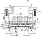
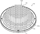
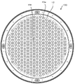
図1は、本発明のプラズマ処理装置の一実施形態に係るプラズマエッチング装置200の要部断面構成を示すものであり、図2は、図1のプラズマエッチング装置200に設けられたシャワーヘッド100の要部構成を示す断面図、図3はシャワーヘッド100の構成を示す斜視図、図4はシャワーヘッド100の上面図である。
FIG. 1 shows a cross-sectional configuration of a main part of a
図2に示すように、シャワーヘッド100は、下側部材1と、この下側部材1の上側に配置された上側部材2の2枚の板状部材を積層させた積層体10から構成されている。これらの下側部材1及び上側部材2は、例えば、表面に陽極酸化処理を施したアルミニウム等から構成されている。このシャワーヘッド100は、図1に示すように、プラズマエッチング装置200の処理チャンバー201に、半導体ウエハ(基板)が載置される載置台202と対向するように配設される。すなわち、図2に示す下側部材1側が図1に示す載置台202と対向する対向面14を形成するように配設される。
As shown in FIG. 2, the
積層体10のうち、載置台202と対向する対向面14を形成する下側部材1には、ガス吐出孔11が多数(図2には1つのみ示す。)形成されており、下側部材1と上側部材2との間には、これらのガス吐出孔11に連通するガス流路12が形成されている。これらのガス吐出孔11は、図1中に矢印で示すように、基板(図1中下側)に向けてガスをシャワー状に供給するためのものである。なお、積層体10の周縁部には、ガス流路12内にガスを導入するためのガス導入部12aが設けられている。
In the laminated body 10, the lower member 1 that forms the facing
また、積層体10には、この積層体10、すなわち、下側部材1と上側部材2とを貫通して、排気孔13が多数(図2には1つのみ示す。)形成されている。これらの排気孔13は、図1,2中に点線の矢印で示すように、基板側(図中下側)から基板と反対側(図中上側)に向けてガスの流れが形成されるように排気を行う排気機構を構成している。排気孔13は、図2に示す下側部材1部分に形成された細径部分13aの直径が例えば0.5〜1.5mm程度とされており、上側部材2部分に形成された大径部分13bの直径が例えば2.0〜5.0mm程度とされている。
In addition, a large number of exhaust holes 13 (only one is shown in FIG. 2) are formed in the laminated body 10 through the laminated body 10, that is, the lower member 1 and the upper member 2. These
排気孔13は、図4に示すように、シャワーヘッド100の周縁部(処理チャンバー201に固定するための固定部となる)を除き、その全領域に亘って略均等に設けられている。排気孔13の数は、例えば12インチ(300mm)径の半導体ウエハを処理するためのシャワーヘッド100の場合、2000〜2500個程度である。なお、図4に示すように、本実施形態では、シャワーヘッド100の外形は、被処理基板である半導体ウエハの外形に合わせて円板状に構成されている。
As shown in FIG. 4, the
さらに、図1に示すように、積層体10の上側部材2側、すなわち、載置台202と対向する対向面14とは反対側の面(裏面)15側には、棒状に構成された複数の磁石柱16a,16bが立設状態で配設されている。
Further, as shown in FIG. 1, a plurality of rod-shaped members are formed on the upper member 2 side of the laminated body 10, that is, on the surface (back surface) 15 side opposite to the facing
磁石柱16a,16bは、シャワーヘッド100の周縁部に設けられた長さの短い磁石柱16aから構成された第1磁石柱群160aと、シャワーヘッド100の中央部に設けられた長さの長い磁石柱16bから構成された第2磁石柱群160bの2つの異なる磁石柱群に分けられている。
The
第1磁石柱群160aに属する長さの短い磁石柱16aは、連結部材17aによって連結され、図1中左側に示される駆動機構161aに接続されている。そして、この駆動機構161aによって第2磁石柱群160bとは独立に上下動可能とされている。一方、第2磁石柱群160bに属する長さの長い磁石柱16bは、連結部材17bによって連結され、図1中右側に示される駆動機構161bに接続されている。そして、この駆動機構161bによって第1磁石柱群160aとは独立に上下動可能とされている。
The
磁石柱16a,16bは、例えば、図3に示すように、シャワーヘッド100の周縁部(処理チャンバー201に固定するための固定部となる)を除き、その全領域に亘って略均等に設けられている。なお、図3では、磁石柱16a同士を連結する連結部材17a及び磁石柱16b同士を連結する連結部材17bについては図示を省略している。
For example, as shown in FIG. 3, the
磁石柱16a,16bとしては、例えば、アルミニウム等の金属製の筒状体中に永久磁石を封入して構成したもの、例えば石英等の非金属材料からなる筒状体中に永久磁石を封入して構成したもの等を用いることができる。また、封入する磁石としては、例えば磁性体セラミックスや、磁性流体等の液体状の磁性体を封入してもよい。これらの磁石柱16a,16bは、12インチ(300mm)径の半導体ウエハを処理するためのシャワーヘッド100の場合、例えば数十本から二百数十本程度設けることが好ましい。
As the
第1磁石柱群160a及び第2磁石柱群160bの上下動によって、これらの第1磁石柱群160a及び第2磁石柱群160bと、シャワーヘッド100の排気孔13との間の距離を調節できるようになっている。これは、処理チャンバー201内のシャワーヘッド100と載置台202との間の処理空間内から、シャワーヘッド100の裏面15側の排気空間へのプラズマのリーク状態を調整するための機構である。
The distance between the first
すなわち、例えば、第1磁石柱群160a及び第2磁石柱群160bを、図1中下方に位置させて排気孔13に近接させた際には、排気孔13からのプラズマのリークを抑制した状態となる。一方、第1磁石柱群160a及び第2磁石柱群160bを、図1中上方に位置させて排気孔13から離間させた際には、排気孔13からのプラズマのリークを許容した状態となる。また、第1磁石柱群160a及び第2磁石柱群160bと排気孔13との距離が離れるほど、プラズマのリーク領域が拡大するようにプラズマの状態を制御できる。
That is, for example, when the first
さらに、例えば第1磁石柱群160aを図1中上方に位置させて排気孔13から離間させ、第2磁石柱群160bを図1中下方に位置させて排気孔13に近接させた際には、シャワーヘッド100の中央部ではプラズマのリークを抑制した状態となり、シャワーヘッド100の周縁部ではプラズマのリークを許容した状態となる。これによって、中央部と周縁部とで夫々部分的にプラズマ密度等のプラズマの状態を制御できる。
Further, for example, when the first
ところで、上記のようなシャワーヘッド100の裏面15側へのプラズマのリークが多くなり過ぎると、プラズマ処理速度の低下を招く一因となる。このため、シャワーヘッド100の中央部では、常時プラズマのリークを抑制した状態とし、周縁部におけるプラズマのリーク状態のみ可変とすることも可能である。この場合、第2磁石柱群160bについては、駆動機構161bを設けずに、シャワーヘッド100に固定した状態とし、第1磁石柱群160aのみを駆動機構161aによって上下動可能として、シャワーヘッド100の周辺部のみでプラズマのリークの調整を行うようにしてもよい。
By the way, if the plasma leakage to the
さらにまた、本実施形態では、図2に示すように、シャワーヘッド100に、載置台202との対向面14と、反対側の面とを貫通し、対向面14側から裏面15側にプラズマのリークを許容する開閉可能なトリガー孔18が設けられている。このトリガー孔18は、排気孔13の細径部分13aより大径(例えば直径2mm程度)とされており、回転弁19等の開閉機構によって開閉自在とされている。なお、回転弁19は、トリガー孔18より大径の回転軸19aを、側部からトリガー孔18を貫通するように挿入して構成されており、回転軸19aを回転させて、回転軸19aに形成された貫通孔19bの位置を、トリガー孔18に合わせることによって開状態とし、貫通孔19bの位置をずらすことによって閉状態とすることができるようになっている。
Furthermore, in the present embodiment, as shown in FIG. 2, the
上記のように、トリガー孔18は排気孔13の細径部分13aより大径とされており、排気孔13よりプラズマを処理空間側から排気空間側にリークさせ易い性質を有している。したがって、排気孔13からプラズマが処理空間側から排気空間側にリークしていない状態において、このトリガー孔18を開くことによって、積極的にプラズマのリークを生じさせることができる。このトリガー孔18は、複数設けることが好ましく、主にシャワーヘッド100の周縁部に設けることが好ましい。例えば、処理空間における周縁部のプラズマ密度等は、中央部に比べて低下する傾向になる場合が多い。このような場合、例えば、周縁部におけるプラズマのリークを生じさせ、中央部におけるプラズマのリークを生じさせないようにすれば、処理空間内の中央部の電子やイオンが周縁部方向に移動し、処理空間内におけるプラズマ密度等の均一化を図ることができる。
As described above, the
このようにプラズマをシャワーヘッド100の裏面15側にリークさせた場合、磁石柱16a,16bがプラズマに晒されて高温になり磁場性能が劣化する場合がある。このため、磁石柱16a,16bを冷却して磁場性能を維持するための温度調整手段を設けることが好ましい。この場合、例えば温調媒体を循環して冷却する温度調整手段等を用いることができる。
When the plasma is leaked to the
図1に示すように、上記構成のシャワーヘッド100を具備した基板処理装置としてのプラズマエッチング装置200は、電極板が上下平行に対向し、プラズマ形成用電源(図示せず。)が接続された容量結合型平行平板プラズマエッチング装置として構成されている。
As shown in FIG. 1, in a
プラズマエッチング装置200は、例えば表面が陽極酸化処理されたアルミニウム等からなり円筒形状に形成された処理チャンバー(処理容器)201を有しており、この処理チャンバー201は接地されている。処理チャンバー201内には、被処理基板としての半導体ウエハを載置し、かつ、下部電極を構成する載置台202が設けられている。この載置台202には、図示しないプラズマ形成用電源が接続されている。
The
載置台202の上側には、その上に半導体ウエハを静電吸着するための静電チャック203が設けられている。静電チャック203は、絶縁材の間に電極を配置して構成されており、この電極に直流電圧を印加することにより、クーロン力によって半導体ウエハを静電吸着する。また、載置台202には、温度調節媒体を循環させるための流路204が形成されており、静電チャック203上に吸着された半導体ウエハを所定の温度に温度調整できるようになっている。また、処理チャンバー201の側壁部には、半導体ウエハを処理チャンバー201内に搬入、搬出するための開口205が形成されており、ここには、開口205を気密に閉塞するための開閉機構206が設けられている。
On the upper side of the mounting table 202, an
載置台202の上方に、載置台202と所定間隔を隔てて対向するように、シャワーヘッド100が配置されている。そして、シャワーヘッド100が上部電極となり、載置台202が下部電極となる一対の対向電極が形成されている。
The
シャワーヘッド100のガス導入部12aは、処理チャンバー201に設けられたガス供給部207に接続されている。ガス供給部207には、図示しないガス供給機構から所定の処理ガス(エッチングガス)が供給される。
The
また、シャワーヘッド100の上部には、筒状体210が設けられており、この筒状体210には、開閉制御弁及び開閉機構等を介してターボ分子ポンプ等の真空ポンプ(図示せず。)が接続されている。このように、筒状体210の内側が排気路となっており、磁石柱16a,16bは、筒状体210の内側の排気路内に配設されている。
Further, a
プラズマエッチング装置200によって、半導体ウエハのプラズマエッチングを行う場合、まず、半導体ウエハは、開口205から処理チャンバー201内へと搬入され、静電チャック203上に載置される。そして、半導体ウエハが静電チャック203上に静電吸着される。次いで、開口205が閉じられ、真空ポンプ等によって、処理チャンバー201内が所定の真空度まで真空引きされる。
When plasma etching of a semiconductor wafer is performed by the
その後、所定流量の所定の処理ガス(エッチングガス)が、ガス供給部207からシャワーヘッド100のガス導入部12aに供給され、この処理ガスは、シャワーヘッド100のガス流路12を経てガス吐出孔11からシャワー状に載置台202上の半導体ウエハに供給される。
Thereafter, a predetermined processing gas (etching gas) having a predetermined flow rate is supplied from the
そして、処理チャンバー201内の圧力が、所定の圧力に維持された後、載置台202に所定の周波数,例えば13.56MHzの高周波電力が印加される。これにより、上部電極としてのシャワーヘッド100と下部電極としての載置台202との間に高周波電界が生じ、エッチングガスが解離してプラズマ化する。このプラズマによって、半導体ウエハに所定のエッチング処理が行われる。
Then, after the pressure in the
上記エッチング処理において、シャワーヘッド100のガス吐出孔11からシャワー状に供給された処理ガスは、シャワーヘッド100に分散して多数形成された排気孔13から排気されるので、処理チャンバー201の下部から排気を行う場合のように、半導体ウエハの中央部から周辺部に向かうようなガスの流れが形成されることがない。このため、半導体ウエハに供給される処理ガスをより均一化することができる。
In the etching process, the processing gas supplied in a shower shape from the gas discharge holes 11 of the
また、前述したとおり、第1磁石柱群160a及び第2磁石柱群160bの位置の調整と、トリガー孔18の開閉によって、処理チャンバー201の処理空間内のプラズマを、筒状体210の内側の排気空間内にリークさせ、処理空間内のプラズマの状態を制御することができる。これによって、処理空間内のプラズマを均一化することができ、半導体ウエハの各部に均一なエッチング処理を施すことができる。すなわち、処理の面内均一性を向上させることができる。
Further, as described above, by adjusting the positions of the first
このようなプラズマの制御は、処理チャンバー201内のプラズマの状態を計測する計測手段、例えば、プラズマの発光状態からプラズマの状態を検知するプラズマモニターによる計測結果に基づいて、駆動機構161a,161bによる第1磁石柱群160a及び第2磁石柱群160bの移動、及び回転弁19によるトリガー孔18の開閉を制御する制御機構を設けることによって、自動的に行うこともできる。
Such control of the plasma is performed by the driving
そして、所定のプラズマエッチング処理が終了すると、高周波電力の印加及び処理ガスの供給が停止され、上記した手順とは逆の手順で、半導体ウエハが処理チャンバー201内から搬出される。
Then, when the predetermined plasma etching process is completed, the application of the high frequency power and the supply of the processing gas are stopped, and the semiconductor wafer is unloaded from the
以上説明したとおり、本実施形態のプラズマエッチング装置200によれば、処理空間内のプラズマの状態を均一化することができ、半導体ウエハの各部に均一なエッチング処理を施すことができる。
As described above, according to the
また、上記のプラズマエッチング装置200では、シャワーヘッド100に設けた排気孔13から排気を行うので、従来の装置のように、載置台202の周囲又はシャワーヘッド100の周囲に排気経路を設ける必要がない。このため、処理チャンバー201の径をより被処理基板である半導体ウエハの外径に近づけることが可能となり、装置の小型化を図ることができる。また、真空ポンプを、処理チャンバー201の上方に設けており、処理チャンバー201の処理空間により近い部分から排気するので、効率良く排気することができ、真空ポンプの容量を少なくしてさらに小型化を図ることができる。
Further, in the
以上、本発明を、実施形態について説明したが、本発明はかかる実施形態に限定されるものではなく、各種の変形が可能であることは勿論である。 As mentioned above, although this invention was described about embodiment, this invention is not limited to this embodiment, Of course, various deformation | transformation are possible.
11……ガス吐出孔、13……排気孔、16a,16b……磁石柱、17a,17b……連結部材、18……トリガー孔、100……シャワーヘッド、161a,161b……駆動機構、200……プラズマエッチング装置、201……処理チャンバー、202……載置台。
DESCRIPTION OF
Claims (8)
前記シャワーヘッドの前記対向面と反対側の面とを貫通する複数の排気孔と、
前記反対側の面側の前記排気孔と連通した排気空間内に、立設状態で設けられた複数の棒状の磁石柱と、
前記磁石柱の少なくとも一部を移動させて前記排気孔との距離を変更するための移動手段と、
を具備し、
前記磁石柱は、第1の磁石柱群と、前記第1の磁石柱群とは異なる第2の磁石柱群の少なくとも2つの異なる磁石柱群からなり、前記第1の磁石柱群と、前記第2の磁石柱群とは、独立に移動可能とされている
ことを特徴とするプラズマ処理装置。 A processing chamber for processing a substrate inside is provided so as to face a mounting table for mounting the substrate, and from a plurality of gas discharge holes provided on a facing surface facing the mounting table to the substrate. A plasma processing apparatus having a shower head for supplying gas in a shower form,
A plurality of exhaust holes penetrating the opposite surface and the opposite surface of the shower head;
A plurality of rod-shaped magnet columns provided in an upright state in the exhaust space communicating with the exhaust holes on the opposite surface side;
Moving means for moving at least a part of the magnet column to change the distance from the exhaust hole;
Equipped with,
The magnet column is composed of at least two different magnet column groups, a first magnet column group and a second magnet column group different from the first magnet column group, the first magnet column group, A plasma processing apparatus, wherein the plasma processing apparatus is movable independently of the second magnet column group .
前記対向面と前記反対側の面とを貫通し、前記対向面側から前記反対側の面側にプラズマの漏洩を許容する開閉可能なトリガー孔を具備する
ことを特徴とするプラズマ処理装置。 The plasma processing apparatus according to claim 1 ,
A plasma processing apparatus comprising an openable / closable trigger hole penetrating the opposing surface and the opposite surface and allowing leakage of plasma from the opposing surface side to the opposite surface side.
前記トリガー孔を複数具備し、夫々独立に開閉可能とされている
ことを特徴とするプラズマ処理装置。 The plasma processing apparatus according to claim 2 ,
A plasma processing apparatus comprising a plurality of the trigger holes and capable of being opened and closed independently.
前記処理チャンバー内のプラズマの状態を計測する計測手段と、
前記計測手段による計測結果に基づいて、前記移動手段による前記磁石柱の移動及び前記トリガー孔の開閉を制御する制御手段と
を具備したことを特徴とするプラズマ処理装置。 The plasma processing apparatus according to claim 2 or 3 ,
Measuring means for measuring the state of plasma in the processing chamber;
A plasma processing apparatus comprising: control means for controlling movement of the magnetic column by the moving means and opening / closing of the trigger hole based on a measurement result by the measuring means.
前記磁石柱の温度を調整するための温度調整手段を具備した
ことを特徴とするプラズマ処理装置。 The plasma processing apparatus according to any one of claims 1 to 4 ,
A plasma processing apparatus comprising temperature adjusting means for adjusting the temperature of the magnet column.
前記対向面と反対側の面とを貫通する複数の排気孔と、
前記反対側の面側に立設状態で設けられた複数の棒状の磁石柱と、
を具備し、
前記磁石柱は、第1の磁石柱群と、前記第1の磁石柱群とは異なる第2の磁石柱群の少なくとも2つの異なる磁石柱群からなり、前記第1の磁石柱群と、前記第2の磁石柱群とは、独立に移動可能とされている
ことを特徴とするシャワーヘッド。 A processing chamber for processing a substrate inside is provided so as to face a mounting table for mounting the substrate, and from a plurality of gas discharge holes provided on a facing surface facing the mounting table to the substrate. A shower head for supplying gas in a shower form,
A plurality of exhaust holes penetrating the opposite surface and the opposite surface;
A plurality of rod-shaped magnet columns provided in a standing state on the opposite surface side;
Comprising
The magnet column is composed of at least two different magnet column groups, a first magnet column group and a second magnet column group different from the first magnet column group, the first magnet column group, A shower head characterized by being movable independently of the second magnet column group .
前記対向面と前記反対側の面とを貫通し、前記対向面側から前記反対側の面側にプラズマの漏洩を許容する開閉可能なトリガー孔を具備する
ことを特徴とするシャワーヘッド。 The shower head according to claim 6 ,
A shower head comprising an openable and closable trigger hole penetrating the opposing surface and the opposite surface and allowing leakage of plasma from the opposing surface side to the opposite surface side.
前記トリガー孔を複数具備し、夫々独立に開閉可能とされている
ことを特徴とするシャワーヘッド。 The shower head according to claim 7 ,
A shower head comprising a plurality of the trigger holes and capable of being opened and closed independently.
Priority Applications (2)
| Application Number | Priority Date | Filing Date | Title |
|---|---|---|---|
| JP2009218726A JP5367522B2 (en) | 2009-09-24 | 2009-09-24 | Plasma processing apparatus and shower head |
| US12/888,664 US8747609B2 (en) | 2009-09-24 | 2010-09-23 | Plasma processing apparatus and shower head |
Applications Claiming Priority (1)
| Application Number | Priority Date | Filing Date | Title |
|---|---|---|---|
| JP2009218726A JP5367522B2 (en) | 2009-09-24 | 2009-09-24 | Plasma processing apparatus and shower head |
Publications (2)
| Publication Number | Publication Date |
|---|---|
| JP2011071168A JP2011071168A (en) | 2011-04-07 |
| JP5367522B2 true JP5367522B2 (en) | 2013-12-11 |
Family
ID=43755600
Family Applications (1)
| Application Number | Title | Priority Date | Filing Date |
|---|---|---|---|
| JP2009218726A Expired - Fee Related JP5367522B2 (en) | 2009-09-24 | 2009-09-24 | Plasma processing apparatus and shower head |
Country Status (2)
| Country | Link |
|---|---|
| US (1) | US8747609B2 (en) |
| JP (1) | JP5367522B2 (en) |
Families Citing this family (13)
| Publication number | Priority date | Publication date | Assignee | Title |
|---|---|---|---|---|
| JP5179389B2 (en) * | 2008-03-19 | 2013-04-10 | 東京エレクトロン株式会社 | Shower head and substrate processing apparatus |
| JP5444044B2 (en) * | 2010-03-02 | 2014-03-19 | 東京エレクトロン株式会社 | Plasma processing apparatus and shower head |
| US8869742B2 (en) * | 2010-08-04 | 2014-10-28 | Lam Research Corporation | Plasma processing chamber with dual axial gas injection and exhaust |
| EP2747622A4 (en) | 2011-09-06 | 2015-06-03 | Kohler Co | Shower and speaker assembly |
| US10945059B2 (en) | 2011-09-06 | 2021-03-09 | Kohler Co. | Shower assembly |
| US10003873B2 (en) | 2011-09-06 | 2018-06-19 | Kohler Co. | Speaker and shower |
| US8900364B2 (en) * | 2011-11-29 | 2014-12-02 | Intermolecular, Inc. | High productivity vapor processing system |
| USD678468S1 (en) | 2012-04-23 | 2013-03-19 | Kohler Co. | Shower and speaker assembly |
| USD727464S1 (en) | 2013-03-06 | 2015-04-21 | Kohler Co. | Shower |
| WO2020004563A1 (en) * | 2018-06-28 | 2020-01-02 | 京セラ株式会社 | Ceramic sintered body and member for plasma treatment device |
| US12270748B2 (en) * | 2018-09-12 | 2025-04-08 | Lam Research Corporation | Method and apparatus for measuring particles |
| US12170865B2 (en) | 2020-01-02 | 2024-12-17 | Kohler Co. | Speaker system for bath and shower environments |
| USD1003859S1 (en) | 2020-01-02 | 2023-11-07 | Kohler Co. | Speaker system for bath and shower environments |
Family Cites Families (24)
| Publication number | Priority date | Publication date | Assignee | Title |
|---|---|---|---|---|
| EP0566143B1 (en) * | 1992-04-17 | 1999-11-24 | Matsushita Electric Industrial Co., Ltd. | Apparatus and method for generating plasma |
| JP3585578B2 (en) * | 1995-05-30 | 2004-11-04 | アネルバ株式会社 | Plasma processing equipment |
| US6537418B1 (en) * | 1997-09-19 | 2003-03-25 | Siemens Aktiengesellschaft | Spatially uniform gas supply and pump configuration for large wafer diameters |
| JPH11149998A (en) * | 1997-11-14 | 1999-06-02 | Foi:Kk | Plasma processing equipment |
| US6207026B1 (en) * | 1999-10-13 | 2001-03-27 | Applied Materials, Inc. | Magnetron with cooling system for substrate processing system |
| US6322661B1 (en) | 1999-11-15 | 2001-11-27 | Lam Research Corporation | Method and apparatus for controlling the volume of a plasma |
| DE10060002B4 (en) * | 1999-12-07 | 2016-01-28 | Komatsu Ltd. | Device for surface treatment |
| JP4437351B2 (en) * | 2000-01-14 | 2010-03-24 | キヤノンアネルバ株式会社 | Plasma etching equipment |
| US6592709B1 (en) * | 2000-04-05 | 2003-07-15 | Applied Materials Inc. | Method and apparatus for plasma processing |
| US6863835B1 (en) * | 2000-04-25 | 2005-03-08 | James D. Carducci | Magnetic barrier for plasma in chamber exhaust |
| US6403491B1 (en) * | 2000-11-01 | 2002-06-11 | Applied Materials, Inc. | Etch method using a dielectric etch chamber with expanded process window |
| AU2002257299A1 (en) * | 2001-06-19 | 2003-01-02 | Toky0 Electron Limited | A closed-drift hall effect plasma vacuum pump for process reactors |
| JP4009087B2 (en) | 2001-07-06 | 2007-11-14 | アプライド マテリアルズ インコーポレイテッド | Magnetic generator in semiconductor manufacturing apparatus, semiconductor manufacturing apparatus, and magnetic field intensity control method |
| JP3616366B2 (en) * | 2001-10-23 | 2005-02-02 | 東京エレクトロン株式会社 | Substrate processing apparatus and substrate processing method |
| US20040129218A1 (en) * | 2001-12-07 | 2004-07-08 | Toshiki Takahashi | Exhaust ring mechanism and plasma processing apparatus using the same |
| JP4243110B2 (en) * | 2003-01-24 | 2009-03-25 | キヤノンアネルバ株式会社 | Surface treatment equipment |
| JP2004335637A (en) * | 2003-05-06 | 2004-11-25 | Anelva Corp | Etching method and etching apparatus |
| US20050103265A1 (en) | 2003-11-19 | 2005-05-19 | Applied Materials, Inc., A Delaware Corporation | Gas distribution showerhead featuring exhaust apertures |
| KR100539266B1 (en) * | 2004-06-02 | 2005-12-27 | 삼성전자주식회사 | Plasma processing apparatus having segment confinements |
| KR20060005560A (en) * | 2004-07-13 | 2006-01-18 | 삼성전자주식회사 | Semiconductor device manufacturing equipment using plasma |
| JP4412661B2 (en) * | 2004-10-15 | 2010-02-10 | 信越化学工業株式会社 | Plasma processing apparatus and plasma processing method |
| JP2006165173A (en) * | 2004-12-06 | 2006-06-22 | Toshiba Corp | Semiconductor device manufacturing apparatus and manufacturing method |
| JP4601439B2 (en) * | 2005-02-01 | 2010-12-22 | 株式会社日立ハイテクノロジーズ | Plasma processing equipment |
| US7972469B2 (en) * | 2007-04-22 | 2011-07-05 | Applied Materials, Inc. | Plasma processing apparatus |
-
2009
- 2009-09-24 JP JP2009218726A patent/JP5367522B2/en not_active Expired - Fee Related
-
2010
- 2010-09-23 US US12/888,664 patent/US8747609B2/en active Active
Also Published As
| Publication number | Publication date |
|---|---|
| US20110067815A1 (en) | 2011-03-24 |
| JP2011071168A (en) | 2011-04-07 |
| US8747609B2 (en) | 2014-06-10 |
Similar Documents
| Publication | Publication Date | Title |
|---|---|---|
| JP5367522B2 (en) | Plasma processing apparatus and shower head | |
| JP5444044B2 (en) | Plasma processing apparatus and shower head | |
| JP5179389B2 (en) | Shower head and substrate processing apparatus | |
| TWI497583B (en) | Plasma processing device | |
| CN101276734B (en) | Plasma processing apparatus | |
| JP4255747B2 (en) | Plasma processing apparatus and plasma processing method | |
| JP5591585B2 (en) | Plasma processing equipment | |
| KR101850355B1 (en) | Plasma processing apparatus | |
| JP5248370B2 (en) | Shower head and plasma processing apparatus | |
| KR101672856B1 (en) | Plasma processing apparatus | |
| JP6199638B2 (en) | Plasma processing equipment | |
| KR101898079B1 (en) | Plasma processing apparatus | |
| JP2009224441A (en) | Showerhead and substrate processing apparatus | |
| TW201447963A (en) | Inductively coupled plasma processing device | |
| JP5661513B2 (en) | Plasma processing equipment | |
| JP3833173B2 (en) | Vacuum processing apparatus and exhaust ring | |
| JP5718011B2 (en) | Plasma processing apparatus and processing gas supply structure thereof | |
| JP3729769B2 (en) | Plasma processing equipment | |
| US20250364228A1 (en) | Substrate processing apparatus | |
| JP2009212286A (en) | Plasma processing equipment | |
| KR20250080999A (en) | Plasma generating unit and substrate treating apparatus including the same |
Legal Events
| Date | Code | Title | Description |
|---|---|---|---|
| A621 | Written request for application examination |
Free format text: JAPANESE INTERMEDIATE CODE: A621 Effective date: 20120914 |
|
| A977 | Report on retrieval |
Free format text: JAPANESE INTERMEDIATE CODE: A971007 Effective date: 20130617 |
|
| A131 | Notification of reasons for refusal |
Free format text: JAPANESE INTERMEDIATE CODE: A131 Effective date: 20130702 |
|
| A521 | Request for written amendment filed |
Free format text: JAPANESE INTERMEDIATE CODE: A523 Effective date: 20130802 |
|
| TRDD | Decision of grant or rejection written | ||
| A01 | Written decision to grant a patent or to grant a registration (utility model) |
Free format text: JAPANESE INTERMEDIATE CODE: A01 Effective date: 20130903 |
|
| A61 | First payment of annual fees (during grant procedure) |
Free format text: JAPANESE INTERMEDIATE CODE: A61 Effective date: 20130911 |
|
| R150 | Certificate of patent or registration of utility model |
Ref document number: 5367522 Country of ref document: JP Free format text: JAPANESE INTERMEDIATE CODE: R150 Free format text: JAPANESE INTERMEDIATE CODE: R150 |
|
| R250 | Receipt of annual fees |
Free format text: JAPANESE INTERMEDIATE CODE: R250 |
|
| R250 | Receipt of annual fees |
Free format text: JAPANESE INTERMEDIATE CODE: R250 |
|
| R250 | Receipt of annual fees |
Free format text: JAPANESE INTERMEDIATE CODE: R250 |
|
| R250 | Receipt of annual fees |
Free format text: JAPANESE INTERMEDIATE CODE: R250 |
|
| LAPS | Cancellation because of no payment of annual fees |