JP5367335B2 - Sludge volume reduction device, sludge treatment facility using the same, and sludge volume reduction method - Google Patents
Sludge volume reduction device, sludge treatment facility using the same, and sludge volume reduction method Download PDFInfo
- Publication number
- JP5367335B2 JP5367335B2 JP2008255986A JP2008255986A JP5367335B2 JP 5367335 B2 JP5367335 B2 JP 5367335B2 JP 2008255986 A JP2008255986 A JP 2008255986A JP 2008255986 A JP2008255986 A JP 2008255986A JP 5367335 B2 JP5367335 B2 JP 5367335B2
- Authority
- JP
- Japan
- Prior art keywords
- sludge
- injection
- injection pipe
- pipe
- fluid
- Prior art date
- Legal status (The legal status is an assumption and is not a legal conclusion. Google has not performed a legal analysis and makes no representation as to the accuracy of the status listed.)
- Expired - Fee Related
Links
Images
Abstract
Description
本発明は、汚泥減容化装置及びこれを用いた汚泥処理設備並びに汚泥減容化方法に関し、特に、汚泥を減容化するために汚泥の中に含まれる微生物の細胞膜を可溶化し易く構成した汚泥減容化装置及びこれを用いた汚泥処理設備並びに汚泥減容化方法に関する。 The present invention relates to a sludge volume reducing device, a sludge treatment facility using the sludge volume reducing device, and a sludge volume reducing method, and more particularly, to easily solubilize cell membranes of microorganisms contained in sludge in order to reduce sludge volume. The present invention relates to a sludge volume reduction device, a sludge treatment facility using the same, and a sludge volume reduction method.
従来、下水等の汚水を処理する方法として、微生物を用いた生物学的な処理方法が知られている。このような処理方法では、微生物を用いて汚水中の有機物を分解処理する。しかしながら、微生物による分解処理の過程で大量の余剰汚泥が発生する。このような余剰汚泥は産業廃棄物であり、大量に発生する余剰汚泥を可能な限り減容化する処理が必要となる。 Conventionally, biological treatment methods using microorganisms are known as methods for treating sewage such as sewage. In such a treatment method, organic substances in wastewater are decomposed using microorganisms. However, a large amount of excess sludge is generated in the process of decomposition by microorganisms. Such surplus sludge is industrial waste, and it is necessary to reduce the volume of surplus sludge generated as much as possible.
余剰汚泥を減容化するには、余剰汚泥を構成する微生物細胞の細胞膜を破壊(可溶化)することが必要である。余剰汚泥を減容化するための処理方法として、機械的処理法、キャビテーション処理法といった、様々な処理方式がある。これらの処理方法のうち、例えばキャビテーション処理法においては、ポンプによって加圧した汚泥流体を減容化処理装置に噴射導入し、減容化処理装置において急激に流体を減圧することによってキャビテーションを発生させ、気泡の崩壊時に加えられる衝撃力により汚泥を可溶化するよう構成されている。さらに、減容化処理装置内に衝突板を設けて、減容化処理装置に噴射導入された汚泥を衝突板に衝突させることにより、キャビテーションによる衝撃力と衝突板に衝突する衝撃力との複合的な作用によって汚泥の減容化を行っている(例えば、特許文献1)。
しかしながら、上記公報にあるようなキャビテーション処理法では、噴射導入された汚泥流体が、衝突板に向かう過程でキャビテーションにより大幅に減速されるため衝突板に衝突する衝撃力が弱くなり、汚泥を十分に減容化することができない。また、キャビテーションを利用した場合、気泡の崩壊時の衝撃力により減容化処理装置に微小な破壊が起き易く処理装置の寿命が短いことが問題となっている。 However, in the cavitation treatment method as described in the above publication, the injected sludge fluid is greatly decelerated by cavitation in the process toward the collision plate, so the impact force that collides with the collision plate is weakened, and the sludge is sufficiently removed. The volume cannot be reduced. Further, when cavitation is used, there is a problem in that the volume reduction treatment device is liable to be broken easily due to the impact force when the bubbles collapse, and the life of the treatment device is short.
以上のような課題に鑑みて、本発明は、汚泥に十分な衝撃力を加えて減容化することができるように構成された汚泥減容化装置及びこれを用いた汚泥処理設備並びに汚泥減容化方法を提供することを目的とする。 In view of the above problems, the present invention provides a sludge volume reducing device configured to be able to reduce the volume by applying a sufficient impact force to sludge, a sludge treatment facility using the sludge reduction equipment, and sludge reduction. The purpose is to provide a method of inclusion.
前記課題を解決するために本発明に係る汚泥減容化装置は、加圧手段(例えば、実施形態における圧力ポンプ2)で加圧された汚泥流体を噴射する噴射ノズルと、噴射ノズルの下流側に設けられ噴射ノズルよりも大きな直径の噴射管と、噴射管の下流側に設けられ噴射管を流れる汚泥流体が衝突する衝突面(例えば、実施形態における細胞膜破壊壁18)と、噴射ノズルと噴射管との間の噴射管内に空気を導入可能な空気導入口とを具える。
In order to solve the above problems, a sludge volume reducing device according to the present invention includes an injection nozzle that injects sludge fluid pressurized by a pressurizing means (for example, the pressure pump 2 in the embodiment), and a downstream side of the injection nozzle. An injection pipe having a diameter larger than that of the injection nozzle, a collision surface provided on the downstream side of the injection pipe and in contact with sludge fluid flowing through the injection pipe (for example, the cell
また、上記構成の汚泥減容化装置において、噴射管内部には、噴射管の内径よりも外径が小さい管状のパワーチューブが噴射管と略同心に設けられており、当該パワーチューブが噴射管の長手方向に衝突面に向けて延びているのが好ましい。 Further, in the sludge volume reducing device having the above configuration, a tubular power tube having an outer diameter smaller than the inner diameter of the injection tube is provided in the injection tube substantially concentrically with the injection tube, and the power tube is connected to the injection tube. It is preferable to extend toward the collision surface in the longitudinal direction.
また、上記構成の汚泥減容化装置において、衝突面に、当該衝突面から突出する複数の突起部(例えば、円筒形又は三角錐)が設けられているのが好ましい。 In the sludge volume reducing apparatus having the above-described configuration, it is preferable that a plurality of protrusions (for example, a cylindrical shape or a triangular pyramid) protruding from the collision surface are provided on the collision surface.
また、上記構成の汚泥減容化装置において、噴射ノズルから噴射される汚泥流体の噴射圧力が、0.7〜0.9MPaの圧力であるのが好ましい。 Moreover, in the sludge volume reduction apparatus of the said structure, it is preferable that the injection pressure of the sludge fluid injected from an injection nozzle is a pressure of 0.7-0.9 MPa.
一方、前記課題を解決するために本発明に係る汚泥処理設備は、上記汚泥減容化装置と、噴射ノズルに流体を供給する加圧手段と、汚泥流体を収容する汚泥槽とを具える。 On the other hand, in order to solve the above problems, a sludge treatment facility according to the present invention comprises the sludge volume reducing device, a pressurizing means for supplying a fluid to the spray nozzle, and a sludge tank for accommodating the sludge fluid.
また、上記構成の汚泥処理設備において、汚泥流体を減容化し易くするための汚泥可溶化液を貯留する汚泥可溶化液貯留槽を具えているのが好ましい。 Moreover, it is preferable to provide the sludge solubilization liquid storage tank which stores the sludge solubilization liquid for making the volume reduction of sludge fluid easy in the sludge processing equipment of the said structure.
一方、前記課題を解決するために本発明に係る汚泥減容化方法は、加圧手段で加圧された汚泥流体を噴射する噴射ノズルと、噴射ノズルの下流側に設けられ噴射ノズルよりも大きな直径の噴射管と、噴射管の下流側に設けられ噴射管を流れる汚泥流体が衝突する衝突面と、を具える汚泥減容化装置を用いて、加圧手段で加圧された汚泥流体を噴射ノズルから噴射し、衝突面に汚泥流体を衝突させることにより汚泥を減容化させる。 On the other hand, a sludge volume reduction method according to the present invention for solving the above-described problems is an injection nozzle that injects the sludge fluid pressurized by the pressurizing means, and is larger than the injection nozzle provided downstream of the injection nozzle. The sludge fluid pressurized by the pressurizing means is provided using a sludge volume reducing device having a diameter injection pipe and a collision surface that is provided downstream of the injection pipe and that collides with sludge fluid flowing through the injection pipe. The volume of sludge is reduced by spraying from the spray nozzle and causing the sludge fluid to collide with the collision surface.
本発明の汚泥減容化装置及びこれを用いた汚泥処理設備並びに汚泥減容化方法によれば、汚泥減容化装置を構成する噴射ノズルから噴射された圧力流が噴射管内いっぱいに広がったときに高速移動するピストン状態となり、当該圧力流上流側の噴射管内に負圧が生じる。そして、この負圧により汚泥減容化装置に形成された空気導入口から噴射管内に空気が自然吸引され、汚泥流体を噴射管の下流側に向けて圧送する。これにより、噴射ノズルの上流側と下流側との圧力差が緩和されるため、キャビテーションが発生せず汚泥高速流体が減速することがなく、細胞膜破壊壁に衝突する衝撃力をキャビテーションが発生する場合よりも遙かに高くすることができる。また、キャビテーションが発生しないことから装置が破壊されず、汚泥減容化装置の使用寿命を従来よりも伸ばすことができる。 According to the sludge volume reducing device of the present invention, the sludge treatment facility using the sludge volume reducing method, and the sludge volume reducing method, when the pressure flow injected from the injection nozzle constituting the sludge volume reducing device spreads all over the injection pipe. As a result, the piston is moved at a high speed, and a negative pressure is generated in the injection pipe on the upstream side of the pressure flow. And by this negative pressure, air is naturally sucked into the injection pipe from the air inlet formed in the sludge volume reducing device, and the sludge fluid is pumped toward the downstream side of the injection pipe. As a result, the pressure difference between the upstream side and the downstream side of the injection nozzle is alleviated, so that cavitation does not occur, sludge high-speed fluid does not slow down, and cavitation generates impact force that collides with the cell membrane destruction wall Can be much higher. In addition, since the cavitation does not occur, the device is not destroyed, and the service life of the sludge volume reducing device can be extended as compared with the prior art.
また、汚泥減容化装置の噴射管内部にパワーチューブが設けられている。これにより、噴射ノズルから噴射された高圧の汚泥流体が、噴射管内を拡散せずにパワーチューブに沿って案内されて棒状の高速流体となり、高速を保持したまま下流側に流れて前方に位置する衝突面に高い衝撃力で衝突する。これにより、汚泥の中に含まれる微生物の細胞膜を高い衝撃力で破壊させて汚泥を減容させることが可能である。 Moreover, the power tube is provided in the injection pipe of the sludge volume reducing device. As a result, the high-pressure sludge fluid ejected from the ejection nozzle is guided along the power tube without diffusing in the ejection tube to become a rod-like high-speed fluid, and flows downstream while maintaining the high speed, and is positioned forward. Collides with the impact surface with high impact force. As a result, it is possible to reduce the volume of sludge by destroying the cell membrane of microorganisms contained in the sludge with a high impact force.
なお、パワーチューブによって高速を保持したまま汚泥流体が衝突する衝突面に、当該衝突面から突出する複数の突起部(円筒状又は三角錐等)を設ければ、これらの突起部に汚泥中の微生物の細胞膜が衝突することで、細胞膜がさらに破壊され易くなり、効率よく細胞膜を破壊することができる。 If a plurality of protrusions (cylindrical or triangular pyramid) protruding from the collision surface are provided on the collision surface where the sludge fluid collides while maintaining a high speed by the power tube, these protrusions are in the sludge. When the cell membrane of the microorganism collides, the cell membrane is further easily destroyed, and the cell membrane can be efficiently destroyed.
さらに、苛性ソーダや安定化次亜塩素酸水といった微生物の細胞膜を軟らかくするための汚泥可溶化液と処理対象の汚泥とを予め混合した状態で汚泥減容化装置に送るようにすれば、汚泥減容化装置での汚泥流体の減容化処理をより行い易くすることが可能である。 Furthermore, if sludge solubilizing liquid for softening the cell membrane of microorganisms such as caustic soda and stabilized hypochlorous acid water and sludge to be treated are mixed in advance and sent to the sludge volume reducing device, sludge can be reduced. It is possible to make it easier to reduce the volume of sludge fluid in the container.
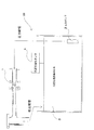
ここで、本発明に係る汚泥減容化装置及びこれを用いた汚泥処理設備並びに汚泥減容化方法の実施形態について説明する。図1は、本発明に係る汚泥処理設備の全体構成を示す概略図である。図1に示すように、汚泥処理設備100は、汚泥を減用化するための汚泥減容化装置1と、汚泥槽3に設置され当該汚泥減容化装置1に汚泥を含む排水を加圧供給する圧力ポンプ2と、汚泥を含む排水を貯留するための汚泥槽3と、汚泥の中に含まれる微生物を処理する汚泥可溶化液を貯留するための汚泥可溶化液貯留槽4と、を具えている。
Here, an embodiment of a sludge volume reducing device according to the present invention, a sludge treatment facility using the same, and a sludge volume reducing method will be described. FIG. 1 is a schematic diagram showing the overall configuration of the sludge treatment facility according to the present invention. As shown in FIG. 1, a
圧力ポンプ2は公知の圧力ポンプを用いることができ、処理対象となる汚泥槽3内の汚泥を吸引して汚泥減容化装置1側に圧送する。また、汚泥可溶化液貯留槽4から汚泥槽3に汚泥可溶化液を送ることができるよう構成されており、汚泥槽3において汚泥と汚泥可溶化液とが混合した上で汚泥減容化装置1側に圧送される。また図示しないが、圧力ポンプ2の吸引口には必要十分なフィルタが設けられており、汚泥槽3内の汚れ成分が前段で濾過されるようになっている。汚泥減容化装置1に送られた汚泥は、汚泥減容化装置1内で減容され、再び汚泥槽3に戻り汚泥槽3内に貯留する。
A known pressure pump can be used as the pressure pump 2, and the sludge in the sludge tank 3 to be treated is sucked and pumped to the sludge
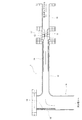
図2は、汚泥減容化装置1の詳細を示す拡大図である。本図に示すように、汚泥減容化装置1は、最も上流側(圧力ポンプ2側)に設けられ図示しない圧力ゲージが設置される圧力ゲージ管15と、圧力ゲージ管15の下流側に接続された噴射ノズル設置管17の中に設けられ圧力ポンプ2で加圧された汚泥流体を噴射する噴射ノズル11と、噴射ノズル設置管17に接続されて当該噴射ノズル11の下流側に設けられ噴射ノズル11よりも大きな直径の噴射管12と、噴射管12の下流側に噴射管12の長手方向に対して略垂直方向に延びるよう接続された前方管14とを具えている。なお、噴射管12の内径は、その上流側から下流側にわたって殆ど同じ内径である。
FIG. 2 is an enlarged view showing details of the sludge
噴射ノズル11は先端側(下流側)が細くなっており、圧力ポンプ2からの汚泥流体が噴射ノズル11を通過する際にさらに加圧され、毎秒約30〜約45m(例えば、圧力流5kg/cm2での速度が毎秒31.30m、圧力流7kg/cm2での速度が毎秒37.04m、圧力流9kg/cm2での速度が毎秒42.00m、圧力流10kg/cm2での速度が毎秒44.27m)の速度で噴射管12に向けて噴射される構成となっている。噴射管12に噴射される噴射速度として、上記の範囲が好適であるが、その理由は、これらの速度よりも噴射速度を低くすると汚泥流体が前方管14に衝突する速度が遅いため減容化しにくくなり、逆にこれらの速度よりも噴射速度が高い場合には減容化装置1にかかる衝撃力に耐え得るよう装置を大型化する必要があり又は衝撃力により装置が壊れやすくなるためである。又、10kg/cm2以上の圧力の汚泥流体が噴射される公知の圧力ポンプは汎用ポンプではなく、汎用的な使用が難しい高価な特殊圧力ポンプであるため、本装置に使用する圧力ポンプとしては適さない。
The
噴射管12内部には、噴射管12の内径よりも外径が小さい管状のパワーチューブ16が噴射管12と略同心に設けられている。このパワーチューブ16は、噴射管12の内部を噴射間の下流側からその上流側に向かって長手方向に延びている。このような構成により、噴射ノズル11から噴射管12に噴射された汚泥流体の高圧のジェット流が、パワーチューブ16に沿って案内されることにより拡散せずに棒状の高速流体となり、高速を保持したまま噴射管12の前方に位置する前方管14の内壁に衝突する。この時の衝撃力により、汚泥の中の微生物の細胞膜が破壊して減容化される。
Inside the
噴射ノズル11と噴射管12との間の噴射ノズル設置管17には、噴射ノズル11と噴射管12との間に設けられた隙間と汚泥減容化装置1の外部とを連通させる空気導入口13が形成されている。この空気導入口13は汚泥減容化装置1の外側表面に環状に複数配設されており、ここから噴射管12の中へと外気が取り込まれるよう構成されている。
The injection
上記のように、圧力ポンプ2により圧送された汚泥流は噴射ノズル11にてさらに加圧され、噴射ノズル11から勢いよく噴射される。噴射ノズル11からのジェット流が噴射管内で拡がることによって高速移動するピストン状態となり、噴射管12の上流側に真空状態が発生する。このように噴射管12の上流側が負圧になることで、空気導入口13から噴射管12内に空気が自然吸引される。この状態では、噴射ノズルの上流側から下流側にわたる高速流体の圧力分布は一様となり減圧される部分が生じないため、キャビテーションが発生しない。したがって、汚泥高速流体は減速されず、前方管14の内壁に衝突する衝撃力が高く汚泥の中の微生物の細胞膜の破壊を効率的に行うことが可能となる。また、キャビテーションが発生しないことから、汚泥減容化装置1が壊れにくくなりその使用寿命を伸ばすことができる。
As described above, the sludge flow pumped by the pressure pump 2 is further pressurized by the
前方管14の内壁面上であって噴射管12の長手方向下流側に位置する部分には、細胞膜破壊壁18が設けられている。この細胞膜破壊壁18の表面には、例えば円柱状又は三角錐状の突起部19が多数設けられている(明瞭のため、図2では三角錐状の突起部19を細胞膜破壊壁18に対して誇張して図示している)。これにより、噴射管12内を高速で流れてきた汚泥流体の中の微生物の細胞膜が、細胞膜破壊壁18表面に形成された突起部19に衝突することで破壊され易くなり、効率よく細胞膜を破壊することができる。また、前方管14の内径は噴射管12の内径の2倍以上に設定されており、これにより表面積の大きな細胞膜破壊壁18が前方管14の内部に設置され、細胞膜破壊壁18に衝突する汚泥流体の中の微生物の細胞膜を効率よく破壊することが可能となる。
A cell
なお、汚泥を減容化するためには、噴射管12内に噴射された高速の汚泥流体を何らかの手段に衝突させればよいため、汚泥減容化装置1は上記のような構成に限られない。上述の実施形態は前方管14の細胞膜破壊壁18に汚泥を衝突させる構成であるが、例えば、前方管14を噴射管12に接続せずに噴射管12の下流側出口付近に衝突板を設け、この衝突板に高速の汚泥流体を衝突させる構成であってもよい。また、汚泥の中の微生物の細胞膜を十分に破壊させることが可能であれば、必ずしも細胞膜破壊壁18面上に突起部19を形成する必要はない。
In order to reduce the volume of sludge, the high-speed sludge fluid injected into the
さらに、上述のように、汚泥流体には微生物の細胞膜を軟らかくするための汚泥可溶化液が混合しており、細胞膜破壊壁18に衝突する汚泥流体の中の微生物の細胞膜が破壊し易くなっている。汚泥可溶化液として、苛性ソーダを含むpH11〜12のアルカリ性溶液、又は除菌効果を有する安定化次亜塩素酸水が好適であるが、これらに限定されず他のものであってもよい。
Furthermore, as described above, the sludge fluid is mixed with a sludge solubilizing solution for softening the cell membrane of microorganisms, and the cell membrane of microorganisms in the sludge fluid that collides with the cell
1 汚泥減容化装置
2 圧力ポンプ(加圧手段)
3 汚泥槽
4 汚泥可溶化液貯留槽
11 噴射ノズル
12 噴射管
13 空気導入口
14 前方管
16 パワーチューブ
17 噴射ノズル設置管
18 細胞膜破壊壁(衝突面)
19 突起部
100 汚泥処理設備
1 Sludge volume reduction device 2 Pressure pump (pressurizing means)
DESCRIPTION OF SYMBOLS 3 Sludge tank 4 Sludge solubilization
19
Claims (7)
加圧手段で加圧された汚泥流体を噴射する噴射ノズルと、前記噴射ノズルの下流側に設けられ前記噴射ノズルよりも大きな直径の噴射管と、前記噴射管の下流側に設けられ前記噴射管を流れる汚泥流体が衝突する衝突面と、前記噴射ノズルと前記噴射管との間の前記噴射管内に空気を導入可能な空気導入口とを具えており、
前記噴射ノズルから噴射される汚泥流体の速度が、30m/s乃至45m/sであることを特徴とする装置。 A sludge volume reduction device,
An injection nozzle that injects sludge fluid pressurized by the pressurizing means; an injection pipe that is provided on the downstream side of the injection nozzle and has a larger diameter than the injection nozzle; and the injection pipe that is provided on the downstream side of the injection pipe A collision surface on which sludge fluid flowing through the air collides, and an air introduction port capable of introducing air into the injection pipe between the injection nozzle and the injection pipe ,
Velocity of the sludge fluid injected from the injection nozzle, 30 m / s to 45 m / s der Rukoto apparatus according to claim.
加圧手段で加圧された汚泥流体を噴射する噴射ノズルと、前記噴射ノズルの下流側に設けられ前記噴射ノズルよりも大きな直径の噴射管と、前記噴射管の下流側に設けられ前記噴射管を流れる汚泥流体が衝突する衝突面と、前記噴射ノズルと前記噴射管との間の前記噴射管内に空気を導入可能な空気導入口と、を具える汚泥減容化装置を用いて、
前記加圧手段で加圧された汚泥流体を、30m/s乃至45m/sの速度で前記噴射ノズルから噴射し、前記衝突面に汚泥流体を衝突させることにより汚泥を減容化させることを特徴とする方法。 A sludge volume reduction method,
An injection nozzle that injects sludge fluid pressurized by the pressurizing means; an injection pipe that is provided on the downstream side of the injection nozzle and has a larger diameter than the injection nozzle; and the injection pipe that is provided on the downstream side of the injection pipe Using a sludge volume reducing device comprising a collision surface on which sludge fluid flowing through the air collides, and an air introduction port capable of introducing air into the injection pipe between the injection nozzle and the injection pipe ,
The sludge fluid pressurized by the pressurizing means is ejected from the spray nozzle at a speed of 30 m / s to 45 m / s, and sludge fluid is collided with the collision surface to reduce the volume of sludge. And how to.
Priority Applications (1)
| Application Number | Priority Date | Filing Date | Title |
|---|---|---|---|
| JP2008255986A JP5367335B2 (en) | 2008-10-01 | 2008-10-01 | Sludge volume reduction device, sludge treatment facility using the same, and sludge volume reduction method |
Applications Claiming Priority (1)
| Application Number | Priority Date | Filing Date | Title |
|---|---|---|---|
| JP2008255986A JP5367335B2 (en) | 2008-10-01 | 2008-10-01 | Sludge volume reduction device, sludge treatment facility using the same, and sludge volume reduction method |
Publications (2)
| Publication Number | Publication Date |
|---|---|
| JP2010082574A JP2010082574A (en) | 2010-04-15 |
| JP5367335B2 true JP5367335B2 (en) | 2013-12-11 |
Family
ID=42247060
Family Applications (1)
| Application Number | Title | Priority Date | Filing Date |
|---|---|---|---|
| JP2008255986A Expired - Fee Related JP5367335B2 (en) | 2008-10-01 | 2008-10-01 | Sludge volume reduction device, sludge treatment facility using the same, and sludge volume reduction method |
Country Status (1)
| Country | Link |
|---|---|
| JP (1) | JP5367335B2 (en) |
Families Citing this family (2)
| Publication number | Priority date | Publication date | Assignee | Title |
|---|---|---|---|---|
| JP6096526B2 (en) * | 2013-02-13 | 2017-03-15 | 株式会社日本水処理技研 | Polishing machine, contaminant removal system using the same, and contaminant removal method |
| KR102143001B1 (en) * | 2013-11-01 | 2020-08-11 | 에스케이이노베이션 주식회사 | The shredding process of oleaginous microorganism using supersonic disperser and manufacturing method of bio-oil using it |
Family Cites Families (5)
| Publication number | Priority date | Publication date | Assignee | Title |
|---|---|---|---|---|
| JPH01164500A (en) * | 1987-12-18 | 1989-06-28 | Pub Works Res Inst Ministry Of Constr | Anaerobic digestion process |
| JPH0661560B2 (en) * | 1988-02-26 | 1994-08-17 | 宇部興産株式会社 | Treatment method of activated excess sludge |
| JP3326500B2 (en) * | 2000-09-27 | 2002-09-24 | 株式会社東京フローメータ研究所 | Processing equipment for processing objects containing microorganisms |
| JP2004202368A (en) * | 2002-12-25 | 2004-07-22 | Babcock Hitachi Kk | Method and apparatus for treating activated sludge |
| JP3864169B2 (en) * | 2004-08-19 | 2006-12-27 | ダイヤモンドエンジニアリング株式会社 | Sludge treatment method and sludge treatment equipment |
-
2008
- 2008-10-01 JP JP2008255986A patent/JP5367335B2/en not_active Expired - Fee Related
Also Published As
| Publication number | Publication date |
|---|---|
| JP2010082574A (en) | 2010-04-15 |
Similar Documents
| Publication | Publication Date | Title |
|---|---|---|
| US20070287917A1 (en) | Method for Collapsing Microbubbles | |
| KR101937133B1 (en) | Micro and nano bubble generating method, generating nozzle, and generating device | |
| EP3061520B1 (en) | Microbubble generating device and contaminated water purifying system provided with microbubble generating device | |
| KR100799663B1 (en) | Apparatus for preparing sterilized water by using ozone | |
| JP2007117799A (en) | Microbubble generator and microbubble generating apparatus using the same | |
| JP2007152268A (en) | Sludge reducing device | |
| JP6449531B2 (en) | Microbubble generator | |
| JP5367335B2 (en) | Sludge volume reduction device, sludge treatment facility using the same, and sludge volume reduction method | |
| JP2011101827A (en) | Saturated water generator, and apparatus for making saturated water or saturated liquid | |
| KR101166457B1 (en) | Apparatus for generating micro bubbles with two stage complex structure including vortex generating part and vortex removing part and method for generating micro bubbles using that | |
| KR101688638B1 (en) | Apparatus for cleaning organic matter using fine ozone bubble | |
| JP5261368B2 (en) | Activated sludge treatment equipment | |
| JP2006055737A (en) | Sludge treatment method and sludge treatment apparatus | |
| JP4925193B2 (en) | Refined mixing device and refined mixing method for multiphase fluid | |
| JP5604003B2 (en) | Ballast underwater aquatic organism killing device | |
| JP2011005359A (en) | Organic waste liquid treatment apparatus and method | |
| JP2011072903A (en) | Method and device of generating bubble, and treatment apparatus employing device | |
| JP2008086986A (en) | Microbubble generating device and water treatment apparatus using the same | |
| KR100445301B1 (en) | Ozone Sterilization Method and Device for Water Supply Drainage | |
| JP4364876B2 (en) | Gas dissolving device | |
| JP2012106189A (en) | Device of generating bubble-containing liquid | |
| JP2001009447A (en) | Jet.reactor | |
| KR100842786B1 (en) | Dissolution oxygen generator by using a floating bubble | |
| JP2000254483A (en) | Cavitation reactor | |
| JP3901370B2 (en) | Decomposition treatment apparatus and method for harmful organic compounds in water |
Legal Events
| Date | Code | Title | Description |
|---|---|---|---|
| A621 | Written request for application examination |
Free format text: JAPANESE INTERMEDIATE CODE: A621 Effective date: 20110810 |
|
| A977 | Report on retrieval |
Free format text: JAPANESE INTERMEDIATE CODE: A971007 Effective date: 20120316 |
|
| A131 | Notification of reasons for refusal |
Free format text: JAPANESE INTERMEDIATE CODE: A131 Effective date: 20121002 |
|
| A521 | Request for written amendment filed |
Free format text: JAPANESE INTERMEDIATE CODE: A523 Effective date: 20121126 |
|
| TRDD | Decision of grant or rejection written | ||
| A01 | Written decision to grant a patent or to grant a registration (utility model) |
Free format text: JAPANESE INTERMEDIATE CODE: A01 Effective date: 20130827 |
|
| A61 | First payment of annual fees (during grant procedure) |
Free format text: JAPANESE INTERMEDIATE CODE: A61 Effective date: 20130911 |
|
| R150 | Certificate of patent or registration of utility model |
Ref document number: 5367335 Country of ref document: JP Free format text: JAPANESE INTERMEDIATE CODE: R150 Free format text: JAPANESE INTERMEDIATE CODE: R150 |
|
| R250 | Receipt of annual fees |
Free format text: JAPANESE INTERMEDIATE CODE: R250 |
|
| R250 | Receipt of annual fees |
Free format text: JAPANESE INTERMEDIATE CODE: R250 |
|
| LAPS | Cancellation because of no payment of annual fees |