JP5366942B2 - Air purifier with holder - Google Patents
Air purifier with holder Download PDFInfo
- Publication number
- JP5366942B2 JP5366942B2 JP2010513244A JP2010513244A JP5366942B2 JP 5366942 B2 JP5366942 B2 JP 5366942B2 JP 2010513244 A JP2010513244 A JP 2010513244A JP 2010513244 A JP2010513244 A JP 2010513244A JP 5366942 B2 JP5366942 B2 JP 5366942B2
- Authority
- JP
- Japan
- Prior art keywords
- opening
- state
- wall
- volatile material
- permeable membrane
- Prior art date
- Legal status (The legal status is an assumption and is not a legal conclusion. Google has not performed a legal analysis and makes no representation as to the accuracy of the status listed.)
- Expired - Fee Related
Links
- 239000000463 material Substances 0.000 claims abstract description 46
- 239000012528 membrane Substances 0.000 claims abstract description 33
- 239000000126 substance Substances 0.000 claims description 6
- 238000003892 spreading Methods 0.000 description 48
- 230000007480 spreading Effects 0.000 description 48
- 238000005507 spraying Methods 0.000 description 28
- 239000007921 spray Substances 0.000 description 11
- 230000002093 peripheral effect Effects 0.000 description 6
- 239000003570 air Substances 0.000 description 5
- 238000013461 design Methods 0.000 description 4
- 238000009792 diffusion process Methods 0.000 description 4
- 238000012986 modification Methods 0.000 description 4
- 230000004048 modification Effects 0.000 description 4
- 239000000853 adhesive Substances 0.000 description 3
- 230000001070 adhesive effect Effects 0.000 description 3
- 238000009826 distribution Methods 0.000 description 3
- 238000004519 manufacturing process Methods 0.000 description 3
- 241000533950 Leucojum Species 0.000 description 2
- 241001465754 Metazoa Species 0.000 description 2
- 239000002386 air freshener Substances 0.000 description 2
- 239000012080 ambient air Substances 0.000 description 2
- 239000000123 paper Substances 0.000 description 2
- 239000004033 plastic Substances 0.000 description 2
- 229920003023 plastic Polymers 0.000 description 2
- 230000002411 adverse Effects 0.000 description 1
- 238000005452 bending Methods 0.000 description 1
- 230000015572 biosynthetic process Effects 0.000 description 1
- 239000011093 chipboard Substances 0.000 description 1
- 239000003086 colorant Substances 0.000 description 1
- 230000003247 decreasing effect Effects 0.000 description 1
- 238000011161 development Methods 0.000 description 1
- 230000000694 effects Effects 0.000 description 1
- 239000003205 fragrance Substances 0.000 description 1
- 239000003292 glue Substances 0.000 description 1
- 238000000034 method Methods 0.000 description 1
- 239000011087 paperboard Substances 0.000 description 1
- 230000000149 penetrating effect Effects 0.000 description 1
- 238000002360 preparation method Methods 0.000 description 1
- 238000011160 research Methods 0.000 description 1
- 238000012827 research and development Methods 0.000 description 1
- 230000007704 transition Effects 0.000 description 1
- 239000003039 volatile agent Substances 0.000 description 1
- 239000002699 waste material Substances 0.000 description 1
Images


Classifications
-
- A—HUMAN NECESSITIES
- A61—MEDICAL OR VETERINARY SCIENCE; HYGIENE
- A61L—METHODS OR APPARATUS FOR STERILISING MATERIALS OR OBJECTS IN GENERAL; DISINFECTION, STERILISATION OR DEODORISATION OF AIR; CHEMICAL ASPECTS OF BANDAGES, DRESSINGS, ABSORBENT PADS OR SURGICAL ARTICLES; MATERIALS FOR BANDAGES, DRESSINGS, ABSORBENT PADS OR SURGICAL ARTICLES
- A61L9/00—Disinfection, sterilisation or deodorisation of air
- A61L9/015—Disinfection, sterilisation or deodorisation of air using gaseous or vaporous substances, e.g. ozone
- A61L9/04—Disinfection, sterilisation or deodorisation of air using gaseous or vaporous substances, e.g. ozone using substances evaporated in the air without heating
- A61L9/12—Apparatus, e.g. holders, therefor
-
- A—HUMAN NECESSITIES
- A01—AGRICULTURE; FORESTRY; ANIMAL HUSBANDRY; HUNTING; TRAPPING; FISHING
- A01M—CATCHING, TRAPPING OR SCARING OF ANIMALS; APPARATUS FOR THE DESTRUCTION OF NOXIOUS ANIMALS OR NOXIOUS PLANTS
- A01M1/00—Stationary means for catching or killing insects
- A01M1/20—Poisoning, narcotising, or burning insects
- A01M1/2022—Poisoning or narcotising insects by vaporising an insecticide
- A01M1/2027—Poisoning or narcotising insects by vaporising an insecticide without heating
- A01M1/2055—Holders or dispensers for solid, gelified or impregnated insecticide, e.g. volatile blocks or impregnated pads
Landscapes
- Life Sciences & Earth Sciences (AREA)
- Pest Control & Pesticides (AREA)
- Health & Medical Sciences (AREA)
- General Health & Medical Sciences (AREA)
- Toxicology (AREA)
- Engineering & Computer Science (AREA)
- Insects & Arthropods (AREA)
- Wood Science & Technology (AREA)
- Zoology (AREA)
- Environmental Sciences (AREA)
- Epidemiology (AREA)
- Animal Behavior & Ethology (AREA)
- Public Health (AREA)
- Veterinary Medicine (AREA)
- Packaging Of Annular Or Rod-Shaped Articles, Wearing Apparel, Cassettes, Or The Like (AREA)
- Packages (AREA)
- Catching Or Destruction (AREA)
- Disinfection, Sterilisation Or Deodorisation Of Air (AREA)
Abstract
Description
関連出願への相互参照
本出願は、2006年4月3日に出願された米国特許出願番号第11/396,755号の一部継続出願である。当該出願の全内容を参照によって本願明細書に援用する。
連邦政府資金援助研究開発に関する参照
Cross-reference to related applications This application is a continuation-in-part of US patent application Ser. No. 11 / 396,755, filed Apr. 3, 2006. The entire contents of that application are incorporated herein by reference.
Reference on federal funding research and development
連邦支援の研究又は開発に関する参照
該当なし
Reference to federally supported research or development N / A
連続リスト
該当なし
Continuous list Not applicable
本発明は、広く、揮発性材料散布システムに関し、より詳細には、調節可能なチップボード・ホルダと組み合わされた揮発性材料散布器に関する。 The present invention relates generally to volatile material dispensing systems, and more particularly to volatile material dispensing devices in combination with adjustable chipboard holders.
職場や家庭に香りをもたらすのに、揮発性材料散布器が用いられてきた。このような散布器の1つとして、写真立てとポプリホルダを組み合わせた装飾的デザインがある。このデザインは、互いに角度を成す前面パネル及び後面パネルを含む。前面パネルの中央には凹みがあり、写真を挿入する領域が設けられている。これらの前面パネルと後面パネルとを、ブリッジがつないでいる。 Volatile material spreaders have been used to bring scents to the workplace and home. One such spreader is a decorative design that combines a photo frame and a potpourri holder. The design includes a front panel and a rear panel that are angled with respect to each other. There is a recess in the center of the front panel, and an area for inserting a photograph is provided. These front panel and rear panel are connected by a bridge.
別のこのような散布器の装飾的デザインとして、空気清浄器と写真立てを組み合わせたものが挙げられる。この写真立ては前面及び後面を含み、前面には外側に延出する2つの長方形をした段付き部分があり、後面は平面である。この写真立ての上部付近には、前面及び後面を貫通する穴が開いている。 Another decorative design of such a spreader is a combination of an air purifier and a photo frame. The photo frame includes a front surface and a rear surface, and the front surface has two rectangular stepped portions extending outward, and the rear surface is a flat surface. In the vicinity of the upper part of this photo frame, there are holes that penetrate the front and rear surfaces.
更に別の散布器は、第1パネル及び第2パネルを含む。これらの第1パネルと第2パネルとを基部が結合することによって、この散布器をテント型に支持する台がもたらされる。第2側面パネルからは、タブが延出している。このタブを捕らえる手段が、第1側面パネルに設けられている。これらの側面パネルのうちの一方には、揮発性材料が充填された容器を取り付けるための開口部が設けられている。 Yet another dispenser includes a first panel and a second panel. The base part of these first and second panels joins to provide a platform for supporting the spreader in a tent shape. A tab extends from the second side panel. Means for catching the tab are provided on the first side panel. One of these side panels is provided with an opening for attaching a container filled with a volatile material.
一実施形態によれば、揮発性物質の放出に適した装置は、前面及び後面を有するディスプレイフレームと、後面に配置された開口部とを含む。更に、装置はディスプレイフレーム内に配置された散布器を含む。散布器は、揮発性物質を保持するブリスターと、ブリスターの開放端を覆うように延出する透過膜とを含む。後面は、ディスプレイフレーム上部にヒンジにより接続される、一体形成された脚部材を含む。一体形成された脚部材は、第1の状態と第2の状態との間でヒンジを軸として作動可能である。更に、後面の近傍に透過膜が配置され、透過膜を通じて揮発性物質が放出することを制御する。 According to one embodiment, an apparatus suitable for the emission of volatile materials includes a display frame having a front surface and a rear surface, and an opening disposed on the rear surface. In addition, the apparatus includes a spreader disposed within the display frame. The spreader includes a blister that holds volatile material and a permeable membrane that extends to cover the open end of the blister. The rear surface includes integrally formed leg members connected to the top of the display frame by hinges. The integrally formed leg member is operable between the first state and the second state around the hinge. Further, a permeable membrane is disposed in the vicinity of the rear surface to control the release of volatile substances through the permeable membrane.
別の実施形態によれば、散布システムは、前セグメント及び後セグメントを有するフレームと、後セグメントに配置された開口部とを含む。更に、散布システムはフレーム内に配置された散布器を含む。散布器は、揮発性物質を保持するブリスターと、ブリスターの開放端を覆うように延出する透過膜とを含む。更に、付加価値を有する特徴がフレームに含まれる。後セグメントは、フレームの上部にヒンジで接続された一体形成された脚を含む。一体形成された脚は第1の状態と第2の状態との間でヒンジを軸として作動可能である。更に、透過膜は後セグメントに対向して配置される。 According to another embodiment, the dispensing system includes a frame having a front segment and a rear segment, and an opening disposed in the rear segment. Furthermore, the spraying system includes a sprayer disposed in the frame. The spreader includes a blister that holds volatile material and a permeable membrane that extends to cover the open end of the blister. Furthermore, features with added value are included in the frame. The rear segment includes integrally formed legs that are hinged to the top of the frame. The integrally formed leg is operable between the first state and the second state around the hinge. Further, the permeable membrane is disposed to face the rear segment.
更に別の実施形態によれば、散布システムへの組み付けに適した略平坦なブランクは、第1の開口部を定義する第1の壁セグメントと、第1の折り目に沿って第1の壁セグメントの第1端にヒンジにより接続された第2の壁セグメントとを含む。第2の壁セグメントは、第2の開口部を覆うように延出する第1の取り外し可能な面を含む。更に、ブランクは、第2の折り目に沿って第1の壁セグメントの第2端にヒンジにより接続される第3の壁セグメントと、第3の折り目に沿って第3の壁セグメントの端部にヒンジにより接続される第4の壁セグメントとを含む。更に、第4の壁セグメントは、第3の開口部を覆うように延出する第2の取り外し可能な面を含む。第1の開口部及び第2の開口部は、組み付けられた状態で相互に位置合わせされるべく適合される。 According to yet another embodiment, a substantially flat blank suitable for assembly to a dispensing system includes a first wall segment defining a first opening and a first wall segment along a first fold. And a second wall segment connected to the first end of the first wall by a hinge. The second wall segment includes a first removable surface that extends to cover the second opening. The blank further includes a third wall segment hingedly connected to the second end of the first wall segment along the second fold, and an end of the third wall segment along the third fold. And a fourth wall segment connected by a hinge. Further, the fourth wall segment includes a second removable surface that extends to cover the third opening. The first opening and the second opening are adapted to be aligned with each other in the assembled state.
本発明のその他の態様及び利点は、以下の詳細な説明を読むと共に図面を参照すれば明らかとなるであろう。 Other aspects and advantages of the present invention will become apparent upon reading the following detailed description and upon reference to the drawings in which:
図1を参照すると、揮発性材料散布システム20が示されている。この散布システム20は、揮発性材料散布器22及びディスプレイフレーム24を含む。このフレーム24は、第1状態と第2状態との間を動作可能であって、これにより、本発明の散布システム20の様々な利用法がユーザにもたらされる。
Referring to FIG. 1, a volatile
図1は、第1状態のディスプレイフレーム24を示している。このディスプレイフレーム24の前面26は、第1壁部28から成る。この第1壁部28は、ほぼ長方形をしており、幅が約3.5インチ(約8.9cm)で高さが約5インチ(約12.7cm)である。この前壁部28には、カバー30が設けられ、その周囲の穿孔部32によって付着されている。このカバー30は、その上方角から剥離されている弧状部を除けば、ほぼ正方形である。この剥離部は、スロット34を画定している。カバー30は、前面26の幅に対してほぼ中央に置かれていると共に、ディスプレイフレーム24の上端38よりも下端36の近くに位置付けられている。第1壁部28の上端38付近には、穴40が設けられている。
FIG. 1 shows the
カバー30は、更に図2〜図5に示されている散布器22を覆っている。図2及び図3を参照すると、この散布器22若しくはカートリッジは、ブリスター44、周辺フランジ46、並びに、これらのブリスター44及びフランジ46に取り外し可能に付着された非透過性ラミネート48を備える。ブリスター44は、無孔透過性膜50及びカップ型構造52若しくはリザーバを含む。カップ型構造52は、底壁54及び4つの側壁56を含み、これらは、透過性膜50と共に、揮発性材料58(図4、5)を収容する密閉リザーバとして機能する。具体例として、これらのカップ型構造52及び透過性膜50は、透明や半透明の材料からできており、このため、揮発性材料58がこれらのカップ型構造52及び透過性膜50を通して見える。周辺フランジ46は、平面状であり、カップ型構造52の上端に結合していると共に、これらの上端から外側に延出している。一実施形態では、この周辺フランジ46は、側壁56の上端から外側に延出していると共に、これらの上端と一体的に形成されている。本発明の散布器22及び揮発性材料58は、米国特許第7,213,770号(この開示内容は、参照によりその全体が本明細書中に組み込まれる)に記載のものと似ている。
The
図4は、第1状況の散布器22を示している。散布器22は、この第1状況において、完全に又はほぼ満杯である。即ち、非透過性ラミネート48がブリスター44から取り外されていないため、揮発性材料58は透過性膜50を通してほとんど又は全く拡散していない。散布器22が満たされていて非透過性ラミネート48が透過性膜50を被覆してい
るときには、揮発性材料58は実質的に拡散しない。具体例として、非透過性ラミネート48は、ユーザがその端部をつかんで剥がすことによって、ブリスター44から取り外される。このような非透過性ラミネート48の取り外しを助ける延長部として、タブ60、延長部、又はその他の把持手段が設けられていてもよい。この延長部は、非透過性ラミネート48の角、端部、及び/又は表面にあってよい。
FIG. 4 shows the
When volatile, the
非透過性ラミネート48が取り外されると、散布器22は、満杯の若しくは第1の状況(図4)から空の若しくは第2の状況(図5)に移り始める。ブリスター18には揮発性材料58が少量残ってもよく、このような状況でも、散布器22は第2状況に達したと見なされる。揮発性材料58が透過性膜50を通して拡散するにつれて、透過性膜50はゆっくりと底壁54上につぶれていく。図5を参照すると、揮発性材料58が透過性膜50を通して拡散した後、散布器22内に収容されている揮発性材料58は少なくなっている。揮発性材料58の拡散後に、新しい空気が散布器22に入ることは実質的にない。その結果、透過性膜50を通して圧力勾配が生じ、散布器22内の圧力よりも周囲空気の圧力の方が高くなる。このような圧力勾配によって、周囲空気は散布器22上に正味の正圧を及ぼし、これにより、透過性膜50が残りの揮発性材料58に対して且つ最終的には底壁54に対して押圧される。
When the
再度、図1を参照すると、非透過性ラミネート48の一部が、スロット34を通して見える。散布システム20は、図6に示されているように、ディスプレイフレーム24からカバー30を取り外すことによって作動する。このカバー30は、その一部をスロット34内でつかんでディスプレイフレーム24から外側に引き剥がすことによって取り外される。このカバー30は、十分な力が及ぼされると第1壁部28から剥がれ、これにより、ほぼ正方形の開口部62がもたらされる。一実施形態における開口部62は、長さ及び幅の寸法が約2.876インチ(約7.305cm)である。この開口部62を通して、非透過性ラミネート48が見えると共に、この非透過性ラミネート48に接触することができる。非透過性ラミネート48は、開口部62の幅及び高さとほぼ同じ距離だけ広がっている。この非透過性ラミネート48は、その一部(例えば、タブ60)をつかんでブリスター44から引き剥がすことによって取り外される。このように非透過性ラミネート48を取り外すことによって、散布器22は第1状況(図4)から第2状況(図5)に移り、これによって、揮発性材料58が空気中に散布される。
Referring again to FIG. 1, a portion of the
ディスプレイフレーム24の後面64が、図7に示されている。この後面64は、第2壁部66及び第3壁部68から成る。第2壁部66は、ほぼ長方形をしており、幅が約3.5インチ(約8.89cm)で高さが約1インチ(約2.54cm)である。第3壁部68は、第2壁部66に一体的に結合されており、幅が約3.5インチ(約8.89cm)で高さが約4インチ(約10.16cm)である。この第3壁部66には、第2開口部70が設けられている。この第2開口部70は、ほぼ正方形をしており、長さ及び幅の寸法が、ブリスター44のカップ型構造52の長さ及び幅の寸法にほぼ等しいかそれよりも大きい。一実施形態では、第2開口部70は、第1壁部28の開口部62よりも小さくされており、長さ及び幅の寸法が約2.313インチ(約5.875cm)である。この第2開口部70は、後面64の幅に対して中央に置かれていると共に、ディスプレイフレーム24の上端38よりも下端36の近くに配置されている。ディスプレイフレーム24の上端38付近には、第2壁部66を貫通する穴40が開いている。カップ型構造52は、第2開口部70を通って突出する。他の実施形態では、このカップ型構造52は、第2開口部70内へ部分的に突出するか或いは第2開口部70とほぼ同一面に合わせられる。図8は、本実施形態においてカップ型構造52が第2開口部70を通ってどの程度延出しているかを示す側面図である。このようにカップ型構造52が第2開口部70を通って延出する距離は、散布器22及び/又はディスプレイフレーム24の寸法を調整することによって変更してもよい。例えば、第1壁部28、第2壁部66、第3壁部68、第4壁部72のうちの1つ以上を厚さの異なる材料から製造して、カップ型構造52が第2開口部70を通って延出する程度を調整してもよい。
The
図1及び図6〜図11の散布システムは、第1状態の散布システム20である。この第1状態は、第1壁部28、第2壁部66、第3壁部68、及び第4壁部72が互いにほぼ平行に位置することを特徴とする。散布器22の一部(例えば、底壁54や非透過性ラミネート48)も、第1壁部28、第2壁部66、第3壁部68、及び第4壁部72と平行である。一般的には、穴40に紐又はその他の部材が通されて、この散布システム20は支持構造(図示せず)から吊り下げられる。別の実施形態では、この散布システム20は、壁又はその他の面に立てかけられるか、或いは、支持面上に置かれてもよい。ユーザが使用可能な第1状態の散布システム20の配置方法は多数ある。
The spraying system of FIGS. 1 and 6 to 11 is a
次に、図9〜図12を参照すると、散布システム20が第2状態にされている。特に図12を参照すると、ディスプレイフレーム24の後面64が示されている。第3壁部68は、ヒンジ74を中心に回転することによって、ディスプレイフレーム24の残りの部分から外側に延出する。この第2状態では、カップ型構造52は、第2開口部70を通って延出しておらず、もはや第2開口部70と同一面になっていない。第3壁部68は、支持部材若しくは脚部材として機能し、支持面76から散布システム20を下支えするのに役立つ。図11は、散布システム20が第2状態においてほぼ逆V字型を呈し、この逆V字型から第2壁部66と第1壁部28の一部とが斜めに延出している様子を示している。第3壁部68の下端78と第1壁部28及び第4壁部72の結合体の下端80とが支持面76上に力を及ぼすことにより、散布システム20は、第2状態における直立位置に維持される。
Next, referring to FIGS. 9 to 12, the spraying
第3壁部68は、第1状態と第2状態を画定する複数の位置との間で動作可能である。散布システム20を第2状態にする前は、この第3壁部68は、第1位置において、第4壁部72と並置され、この第4壁部72とほぼ平行である。ヒンジ74を中心に第3壁部68を回転させることによって、散布システムは第2状態にされる。このように第3壁部68を回転させることによって、第3壁部68は、第4壁部72から角度がつけられ、第2位置に置かれる。散布システム20を第2状態にするのに、第3壁部68は、約1°〜約180°のいずれの角度に位置決めされてもよい。具体例として、第3壁部68の角度は、約20°〜約70°である。
The
散布システム20が第1状態であるか第2状態であるかにかかわらず、散布器22の透過性膜50は、ディスプレイフレーム24の後面64から実質的に離れて位置付けられている。従って、揮発性材料58は、邪魔されることなく空気中に放出されるため、より効率的に拡散することができる。また、透過性膜50は、散布システム20の前面26から見える。従って、ユーザは、大して苦労することなく、散布器22に残っている揮発性材料58のレベルを判別し得る。
Regardless of whether the spreading
図13及び図14は、本発明の散布システム20を製造するのに用いられ得る、1つのタイプのブランク(blank)82を示している。このブランク(ブランクフレーム)82は
、板紙などから製造され、適切な形状に打ち抜かれ得る。図13は、取り外し可能なカバー30及び穴40を備えた第1壁部28の前面84を示している。図14は、この第1壁部28の後面86を示している。この第1壁部28の第1端部88には、ヒンジ90又は折り目によって、第2壁部66がつながっている。この第2壁部66も、穴40並びに前面92及び後面94を含む。この第2壁部66の反対側の端部には、ヒンジ74又は折り目において、第3壁部68がつながっている。この第3壁部68は、第2開口部70並びに前面96及び後面98を含む。第1壁部28の第2端部100には、ヒンジ102又は折り目によって、第4壁部72がつながっている。この第4壁部72は、第2開口部70と同じような寸法の第3開口部104並びに前面106及び後面108を含む。
FIGS. 13 and 14 illustrate one type of blank 82 that may be used to manufacture the dispensing
散布システム20は、第4壁部72の後面108から第3開口部104を通して散布器22のカップ型構造52(図13には示されていない)を挿入することにより組み立てられる。散布器22の周辺フランジ46は、第4壁部72の後面108の第3開口部104周囲部分にホットシールされる。ヒンジ102を中心に第4壁部72を回転させることによって、この第4壁部72の後面108が第1壁部28の後面86にほぼぴったりと重なる。これらの第4壁部72の後面108と第1壁部28の後面86は、合わせてホットシールされる。第4壁部72がこのように位置決めされると、散布器22の非透過性ラミネート48は、第1壁部28のカバー30裏の中央に位置付けられる。2つの穴40が合うように、ヒンジ90を中心に第2壁部66が折り曲げられる。この第2壁部66の後面94も同様に、第1壁部28の後面86にホットシールされる。残りの第3壁部68は第4壁部72にほぼぴったりと重なり、第3壁部68の後面98は第4壁部72の前面106と並置される。
The spreading
ブランク82は、あらゆる他のタイプの紙ベースの材料又は異なる材料(例えば、プラスチック)から構成されてもよい。プラスチックのような異なる材料は、紙ベースの材料には悪影響を及ぼす湿潤環境において有用であり得る。更に、ブランク82及び散布器22の一部は、接着剤又は異なるタイプの糊によって、互いに接着されてもよい。また、ディスプレイフレーム24自体は、美的効果を狙って装飾的な形状としてもよいし、様々な色及び/又は絵を施してもよい。図15及び図16は、そのような1つの散布システム120を示している(散布システム20に用いられているのと同様の構造には、同じ参照番号が付与されている)。この散布システム120は、第1壁部28、第2壁部66、第3壁部68、及び第4壁部72の側壁122が曲線状であることを特徴とする。また、この散布システム120は、穴40に紐124が通されている。この紐124は、支持面(例えば、棒やドアノブ)から散布システム120を支持するのに用いられ得る。また、本実施形態には、廃棄する必要のある材料を省くため、カバー30が無くてもよい。これらの図15及び図16は、他の実施形態において見られ得る様々な壁部のサイズ及び形状に関する変形例を示している。
The blank 82 may be composed of any other type of paper-based material or a different material (eg, plastic). Different materials, such as plastics, can be useful in wet environments that adversely affect paper-based materials. Further, the blank 82 and a portion of the
図17及び図18は、散布システム20に似た別の実施形態である散布システム220を示している。しかしながら、この散布システム220は、第4壁部72の、第1壁部28及び第4壁部72の結合体の下端80付近に、保持部材222が設けられている、という点で異なっている。この保持部材222は、第4壁部72から部分的に切り取られて第3壁部68の方へ外側に曲げられた弾性湾曲部材から構成されている。散布システム220が第1状態であるとき、第3壁部68の下端78の一部は、この保持部材222内に保持される。このように第3壁部68が保持部材222内に保持されることによって、第3壁部68の下端78は第4壁部72に押し当てられる。第3壁部68が保持部材222から取り外されると、散布システム220は第1状態から第2状態に移る。この保持部材222は、散布システム220をよりしっかりと第1状態に維持する手段をもたらす。例えば、この保持部材222は、散布システム220に外部の力が作用することによって、或いは、ヒンジ74が曲がり過ぎて第3壁部68が動くことによって、不用意に状態が移るのを防ぎ得る。その他のタイプ(様々な形状、数、又は位置)の保持部材を用いることも考えられる。更に、保持部材は、これらの図17及び図18に示されているようにディスプレイフレームと一体化していてもよいし、ディスプレイフレームに取り付けられる別個の構造であってもよい。
17 and 18 illustrate another embodiment of a
別の実施形態では、散布システム20、120、220に、様々な形状の開口部及び散布器が設けられている。例えば、散布器22及び/又はカップ状構造体52は、長方形をしていてもよいし、その他のデザイン(例えば、雪片や動物)であってもよい。更に、1つの散布システム20、120、220に、異なる又は同様の揮発物が入った複数の散布器を設けてもよい。また、第1壁部28、第2壁部66、第3壁部68、及び第4壁部72のうちのいくつか又は全てと散布器22とを結合するのに再使用可能な接着剤を用いることも考えられ、そうすると、揮発性材料58が無くなったら、散布システム20、120、220全体を交換する代わりに、散布器22を交換することができる。更に別の実施形態では、散布システム20、120、220は、側部を下にして置いてもよく、この場合、下端36及び上端38は支持面に触れない。正確には、第1壁部28、第2壁部66、第3壁部68、及び第4壁部72の、散布システム20、120、220の左側或いは右側を画定する部分が、支持面付近に位置する。それでも、第3壁部68は、ヒンジ74を中心に回転して第1状態と第2状態との間を遷移し、本明細書中に開示したような本発明の散布システム20、120、220の異なる動作方法をユーザに提供する。当業者は、本開示内容に関して加えられ得る多数の変更を認めるであろう。また、これらの変更は、本開示内容に含まれるよう意図されている。
In another embodiment, the
ここで図19及び20を参照すると、揮発性物質散布システム320(図21〜図28を参照)の更に別の作製方法が示されている。本実施形態では、散布システム320は、前部326と後部328とを有する第1の壁部すなわちセグメント324を含むブランク322を含む。第1の壁セグメント324は幅約4インチ(約10.16cm)、高さ約5.2インチ(約13.2cm)の略矩形をなす。略正方形の第1の開口部330は第1の壁セグメント324の幅方向中央に配置され、その第1端又は下部332近傍に配置される。更に、第1の壁セグメント324は、第1の壁セグメント324の第2端すなわち上部336近傍に配置される第1の穴334を含む。第1の穴334は角部が湾曲した鈍角三角形をなす。なお、他の実施形態では、第1の穴334は他の対称形状あるいは非対称形状を有していてもよい。
Referring now to FIGS. 19 and 20, yet another method of making a volatile material distribution system 320 (see FIGS. 21-28) is shown. In this embodiment, the spreading
第2壁部すなわちセグメント338は、第1のヒンジすなわち折り目340によって第1の壁セグメント324の第1端332に取り付けられる。第2の壁セグメント338は幅約4インチ(約10.16cm)、高さ約3.9インチ(約9.9cm)の略矩形をなす。更に、第2の壁セグメント338は第2の開口部342、前部344及び後部346を含む。第2の開口部342は略正方形をなし、第2の壁セグメント338の幅方向中央に配置される。第1の取り外し可能な面すなわちカバー348が第2の開口部342に設けられ、第1の穿孔セグメント350により第2の開口部342を定義する第2の壁セグメント338の一部に取り付けられる。第1のカバー348は略正方形をなし、その1つの角からアーチ状部分352が取り除かれている。除去された部分は第1のスロット354を定義する。更に、湾曲した係合部材すなわち保持部材356が第1のヒンジ332近傍に設けられる。係合部材356は第1の穿孔セグメント350によって定義され、両対向側にスリットを有する。
The second wall or
第3の壁部すなわちセグメント358は、第2のヒンジすなわち折り目360により第1の壁セグメント324の第2端336に取り付けられる。第3の壁セグメント358は幅約4インチ(約10.16cm)、高さ約1.2インチ(約3.05cm)の略矩形をなす。第3の壁セグメント358は第2の穴362、前部364及び後部366を含む。第2の穴362はヒンジ360近傍に配置されると共に、ヒンジ360を軸に第1の穴334の鏡像となっている。
The third wall or
更に、ブランク322は第3のヒンジすなわち折り目370で第3の壁セグメント358に取り付けられた第4の壁部すなわちセグメント368を含む。第4の壁セグメント368は幅約4インチ(約10.16cm)、高さ約3.8インチ(約9.65cm)の略矩形をなす。第4の壁セグメント368は第3の開口部372、前部374及び後部376を含む。第3の開口部372は略正方形をなし、第4の壁セグメント368の幅方向中央に配置される。第2の取り外し可能な面すなわちカバー378が第3の開口部372に設けられ、第3の開口部372を定義する第4の壁セグメント368の一部に第2の穿孔セグメント380により取り付けられる。第2のカバー378は略正方形をなし、その1つの角から第2のアーチ状部分382が取り除かれている。除去された部分は第2のスロット384を定義する。
Further, the blank 322 includes a fourth wall or
本実施形態では、第1の開口部330及び第3の開口部372は、幅及び高さが約2.3インチ(約5.84cm)の略正方形をなす。なお、他の実施形態では、第1の開口部330及び第3の開口部372は異なる寸法を有してもよい。実際は、第1の開口部330及び第3の開口部372のうち一方又は両方が非正方形をなしてもよい。更に、本実施形態の第2の開口部342は略正方形であるが、第1の開口部330及び第3の開口部372と比べて高さ及び幅寸法が大きい。例えば、本実施形態の第2の開口部342の高さ及び幅は約2.9インチ(約7.37cm)である。同様に、他の実施形態において、第2の開口部342は別の非正方形の形状をなしてもよい。
In the present embodiment, the
以下に詳述されるように、第1の開口部330、第2の開口部342及び第3の開口部372のサイズ及び形状は、共に使用される散布器22に合わせて適合される。例えば、本実施形態において、第1の開口部330は散布器22のカップ状構造体52を受容すべく適合された形状をなす。第1の開口部330はカップ状構造体52の形状と同様の形状をなし、カップ状構造体52と同一又はそれよりも大きい寸法を有することが望ましい。上述したようにカップ状構造体52は矩形、円形、三角形、あるいは雪片状や動物の形状などの任意の対称的あるいは非対称的形状を有することができる。なお、他の実施形態において、第1の開口部330はカップ状構造体52とは異なる形状を有していてもよい。第1の開口部330の寸法は、カップ状構造体52が第1の開口部330から延出することを可能とすべく設定される。同様に、第2の開口部342は散布器22の周縁フランジ46と同様の長さ及び幅寸法を有する。他の実施形態では、第2の開口部342は、散布器22の非透過性ラミネート48より小さくても大きくてもよく、あるいは異なる形状をなしてもよい。なお、本開示では、ラミネート48を散布器22から容易に取り除くことができるように、開口部342からラミネート48にアクセスできるようになっている。最後に、第3の開口部372は任意のサイズ及び形状とすることができ、揮発性物質58が概ね間断なく散布器22から拡散されるべく適合されている。第3の開口部372は、例えば散布器22の透過膜50と同様の形状をなしてもよい。第3の開口部372は、散布システム320が第1の状態にあるとき、揮発性物質58が第3の開口部372から一様に拡散することを可能とすべく透過膜50と略位置合わせされる。更に、周囲に拡散する揮発性物質58に対する障害を大きくしあるいは小さくするため、第3の開口部372のサイズを透過膜50よりも大きくあるいは小さくすることができる。
As described in detail below, the size and shape of the
図21〜図28は、散布システム320のブランク322が、散布器22と共に使用されるためにディスプレイフレーム386に組み付けられる方法を示している。散布システム320は、第1の壁セグメント324の後部328(図20を参照)において、散布器22(図19及び図20には図示せず)のカップ状構造体52を第1の開口部330から挿入することにより組み立てられる。散布器22の周縁フランジ46は、第1の壁セグメント324の、第1の開口部330の外周を囲む部分に取り付けられる。第2の壁セグメント338は、第2の壁セグメント338の後部346を第1の壁セグメント324の後部328と略同一平面上に位置決めすべく第1のヒンジ340を軸に回転される。第1の壁セグメント324及び第2の壁セグメント338の後部328及び346は相互にホットシールされる。第2の壁セグメント338は、散布器22の非透過性ラミネート48が第2の壁セグメント338の第1のカバー348の背後の中央に配置される。同様に、第3の壁セグメント358は、第3の壁セグメント358の後部366を第1の壁セグメント324の後部328と略同一平面上に位置決めすべく第2のヒンジ360を軸に折り曲げられる。これにより第1の壁セグメント324及び第3の壁セグメント358を相互にホットシールできる。第3の壁セグメント358は、第3の壁セグメント358の第2の穴362が第1の壁セグメント324の第1の穴334と位置合わせされるように配置される。残る第4の壁セグメント368の後部376は、第2の壁セグメント338の前部344と略同一平面上となるように設けられる。
FIGS. 21-28 illustrate how the blank 322 of the
散布システム320は、上記実施形態と同様に第1の状態と第2の状態との間で操作可能である。図21、図22及び図27は第1の状態における散布システム320を示している。図21を参照すると、第1の壁セグメント324、第1の開口部330及び第1の穴334を含むディスプレイフレーム386の前面すなわちセグメント388が示されている。散布器22のカップ状構造体52は第1の開口部330から突出する。図22は、第3の壁セグメント358及び第4の壁セグメント368を含むディスプレイフレーム386の後面すなわちセグメント390を示している。上述したように第1の穴334及び第2の穴362は開口部を提供すべく位置合わせされる。これにより、散布システム320がディスプレイフック(図示せず)に配置されることができ、及び/又は第1の穴334及び第2の穴362に紐を通して支持構造物から散布システム320を吊下すべく配置できる。後面390は、更に第2のカバー378に覆われる第3の開口部372を含む。
The
図23〜図26及び図28は、第2の状態における散布システム320を示す。特に図25及び図26を参照すると、後面390が示されている。散布システム320は、第4の壁セグメント368を中間面すなわちセグメント392から離間する方向にヒンジ370を軸に回転させることにより、第2の状態に配置される。中間面すなわちセグメント392は第2の壁セグメント338及び第2の開口部342を含む。第2の状態では、第3の開口部372は第2の開口部342と位置合わせされていない。第4の壁セグメント368は、支持表面(図示せず)から散布システム320を支持する助けとなるべく支持部材又は脚部材として作用する。図28は、散布システム320が第2の状態おいて略逆V字形状を呈することを示している。このとき第3の壁セグメント358及び第1の壁セグメント324の一部は角度をなして延出している。第4の壁セグメント368の下端394、及び組み合わされた第1の壁セグメント324及び第2の壁セグメント338の下端396は、第2の状態において散布システム320を直立位置に維持すべく支持表面上に力を加える。本願明細書中に記載された他の実施形態と同様に、第4の壁セグメント368は、第1の状態と、第2の状態を定義する複数の位置との間で作動可能である。第4の壁セグメント368は、散布システム320を第2の状態とするため、中間面392に対し約1度〜約180度の間の任意の角度に配置されてもよい。例えば、図23は、第4の壁セグメント368がヒンジ370を軸として中間面392に対し約180度上方へ回転され状態におけるディスプレイフレーム386の中間面392を示す。
23-26 and 28 show the
散布システム320は第1又は第2の状態のいずれの操作可能な位置に配置されてもよい。図23を参照すると、第1のカバー348及び第2のカバー378が示されている。第1のカバー348は、ユーザが第1のスロット354に少なくとも1本の指を入れてディスプレイフレーム386から第1のカバー348を引き離すことにより取り除かれる。これにより第1のカバー348が第1の穿孔セグメント350に沿って第2の壁セグメント338から分離される。第1のカバー348が取り除かれると、散布器22の非透過性ラミネート48が露出する。非透過性ラミネート48は上記と同様の方法で散布器22から取り除かれ、揮発性物質58が透過膜50から拡散することが可能となる。第2のカバー378は、ユーザが第2のスロット384に少なくとも1本の指を入れてディスプレイフレーム386(図25を参照)から第2のカバー378を引き離すことにより同様に取り除かれる。これにより第2のカバー378が第2の穿孔セグメント380に沿って第4の壁セグメント368から分離される。別の実施形態では、第2のカバー378が取り除かれると、第1のカバー348及び非透過性ラミネート48を第3の開口部372から取り除くことができるようになる。諸実施形態において、第1のカバー348及び第2のカバー378は完全に取り除かれ、ディスプレイフレーム386から分離される。別の諸実施形態では、カバー348及び378は部分的に取り除かれ、各々第1の穿孔セグメント350及び第2の穿孔セグメント380の一部に沿ってフレーム386に接続された状態を保持する。従って、カバー348及び378を選択的に取り除き、散布システム320を第1の状態と第2の状態との間で作動することにより、周囲に拡散する揮発性物質58に対する障害を大きくしあるいは小さくすることにより、拡散制御を行うことができる。
The spreading
本実施形態において、第1の穿孔セグメント350に沿って第1のカバー348を除去すると、第1のカバー348から係合部材356が解放される。別の実施形態では、係合部材356は第1のカバー348とは別体として提供され、その全体あるいは一部が第1のカバー348に取り付けられない。図27に示されるように、係合部材356は上記保持部材222(図17及び図18を参照)と同様の方法で散布システム320を第1の状態に保持するべく適合される。特に、後面390を中間面392と略同一平面上に位置決めすべく、第4の壁セグメント368の下端394が係合部材356によって保持される。
In this embodiment, removing the
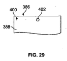
ここで図29〜図31Bを参照すると、ディスプレイフレーム386の上部400の更に別の実施形態が示されている。図29は、ディスプレイフレーム386の前面388及び後面390から延出する小さい円形の穴402を示している。ディスプレイフレーム386を吊下する目的で紐又は他の部材(図示せず)が穴402に通されてもよい。同様にしてディスプレイフレーム386の前面388及び後面390から延出する、側部スリット406を有するより大きい円形開口部404が図30に示されている。当業者には、ディスプレイフレーム386を第1又は第2の状態に支持するために本実施形態を利用しあるいは変更する方法が明らかである。実際には、別の実施形態において、第4の壁セグメント368は約180度(図23を参照)の角度で結合され、ドアノブや他の支持構造物が第3の開口部372に挿入される(図26を参照)。あるいは、第4の壁セグメント368を支持構造物から吊下することを可能とすべく、第3の開口部372と第4の壁セグメント368の縁部との間において第4の壁セグメント368に側部スリット(例えば、図30に示すスリット406)が設けられる。
Referring now to FIGS. 29-31B, yet another embodiment of the top 400 of the
図31A及び図31Bは、付加価値を有する特徴422を含む散布システム420の前面388及び後面390をそれぞれ示す。本実施形態では、付加価値を有する特徴422は取り外し可能なフック424である。取り外し可能なフック424は、上記第1の開口部334及び第2の開口部362と同様の開口部426から延出する。取り外し可能なフックを開口部426から挿入することにより、散布システム420を棒やその他の構造(図示せず)から吊下できる。更に、散布システム420は湾曲した側壁428を含む。
FIGS. 31A and 31B show a
図32は、散布システム420のディスプレイフレーム386として形成されるのに適したブランク430を示している。実際には、ブランク430は以下の点を除いて図19及び図20に示されるブランク322と同一である。取り外し可能なフック424が第1のカバー348内に設けられ、第3の穿孔部分432がフック424の輪郭を形成する。更に、壁セグメント324、338、358、368は湾曲した側壁428を有する。ブランク430は別の方法で折り曲げられ、ブランク322と同様に散布器22が設けられる。これにより図31A及び図31Bに示される散布システム420が形成される。散布システム420を操作可能な状態に配置したいときには、第1のカバー348が第1の穿孔セグメント350に沿って第2の壁セグメント338から取り除かれる。更に、取り外し可能なフック424が、第3の穿孔部分432に沿って第1のカバー348から取り除かれる。次いで、支持構造物に対し散布システム420を支持するために、取り外し可能なフック424が開口部426から挿入されてもよい。このように第1のカバー348を再利用することにより廃棄物が減少し、散布システム420を更にユーザフレンドリーなシステムとすることができる。別の実施形態では、取り外し可能なフック424は第2のカバー378に配置される。
FIG. 32 shows a blank 430 suitable for being formed as the
本願明細書中に開示された散布システムのいずれかに、他の付加価値を有する特徴422が含まれていてもよい。例えば、第1のカバー348及び第2のカバー378はブランド名称、同一製品又は他の製品を将来購入するためのクーポン、取扱説明書、広告、装飾用ステッカー、ラベル、散布システムを支持構造物に取り外し可能に固定するための接着剤及び/又は追加のリフィル散布器を含む。図33に示されるような実施形態において、付加価値を有する特徴422は、第1のカバー348及び第2のカバー378のうち一方又は両方の一部としてそれぞれ提供される。なお、付加価値を有する特徴422は、他の適切な方法で提供でき、例えば追加の挿入物もしくは壁セグメントとして提供されてもよい。
Any of the dispensing systems disclosed herein may include other added value features 422. For example, the
他の実施形態は、本願明細書中に記載された実施形態の個々の特徴の各種組合せを全て包含する。 Other embodiments encompass all of the various combinations of individual features of the embodiments described herein.
本明細書中で説明した空気清浄剤散布システムは、吊り下げ位置と自立位置との間で調節可能であり芳香剤散布器を備えたディスプレイフレームの機能的特徴と美的特徴とを有益に組み合わせている。従って、この空気清浄剤散布システムを用いることにより、ユーザは、家庭又は職場内に空気清浄器をより柔軟に配置することができる。 The air freshener spray system described herein is adjustable between a suspended position and a free-standing position and beneficially combines the functional and aesthetic features of a display frame with a fragrance sprayer. Yes. Therefore, by using this air freshener spraying system, the user can arrange the air purifier more flexibly in the home or workplace.
先の説明を考慮すれば、当業者には多数の変更点が明らかであろう。従って、この説明は、単なる例示と解釈されると共に、当業者が本発明を行って使用し且つ本発明を実施する最良の形態を教示できるようにすることを目的として提示される。添付の特許請求の範囲内に含まれる変更点全てに対する独占権は留保される。 Many modifications will be apparent to those skilled in the art in view of the foregoing description. Accordingly, this description is to be construed as illustrative only and is for the purpose of enabling those skilled in the art to make and use the invention and teach the best mode of carrying out the invention. Exclusive rights to all modifications contained within the scope of the appended claims are reserved.
Claims (8)
前記後面部材の前記開口部と重ね合わされる後面部材用取り外し可能な部材と、
前記ディスプレイフレーム内に配置された散布器と、
を含み、
前記散布器は、揮発性物質を保持するブリスターと、前記ブリスターの開放端を覆うように延出する透過膜とを含み、
前記後面部材は、前記ディスプレイフレームの上部にヒンジにより接続される、一体形成された脚部材を含み、
前記一体形成された脚部材は前記前面部材、前記後面部材、及び前記中間面部材が平行に位置する第1の状態と前記前面部材及び前記中間面部材が平行に位置しかつ前記後面部材が前記前面部材及び前記中間面部材と平行でない第2の状態との間でヒンジを軸として作動可能であり、
前記透過膜は前記後面部材の近傍に配置されると共に、前記第1の状態と前記第2の状態で前記透過膜を通じて前記揮発性物質が放出することを制御し、
前記後面部材用取り外し可能な部材には付加価値が設けられ、
前記付加価値は、ブランド名称、クーポン、広告、取扱説明書、ステッカー、ラベル、シール片及び散布器リフィルからなる群より選択される
揮発性物質を放出すべく適合された装置であって、
前記中間面部材の前記開口部と重ね合わされる中間面部材用取り外し可能な部材を備え、
前記前面部材と前記後面部材とには、フック用開口部が設けられ、
前記装置は、前記前面部材と前記後面部材とに設けられた前記フック用開口部に取り外し可能に挿入されることが可能なフックを更に備え、
前記フックは、前記中間面部材用取り外し可能部材内に取り除き可能な状態で設けられている
ことを特徴とする揮発性物質を放出すべく適合された装置。 A display frame having a front member having an opening, a rear member having an opening, and an intermediate member positioned between the front member and the rear member, and having an opening;
A detachable member for the rear member that is superimposed on the opening of the rear member;
A spreader disposed within the display frame;
Including
The spreader includes a blister that holds a volatile substance, and a permeable membrane that extends to cover an open end of the blister,
The rear member includes an integrally formed leg member connected to the upper portion of the display frame by a hinge,
The integrally formed leg member includes a first state in which the front member, the rear member, and the intermediate member are positioned in parallel, the front member and the intermediate member are in parallel, and the rear member is in the first state. Operable between a front member and a second state not parallel to the intermediate member with the hinge as an axis;
The permeable membrane is disposed in the vicinity of the rear member , and controls the release of the volatile substance through the permeable membrane in the first state and the second state,
The removable member for the rear member is provided with added value,
Said added value is a device adapted to emit a volatile substance selected from the group consisting of brand name, coupon, advertisement, instruction manual, sticker, label, seal strip and sprayer refill ,
A removable member for an intermediate surface member superimposed on the opening of the intermediate surface member;
The front member and the rear member are provided with hook openings.
The apparatus further includes a hook that can be removably inserted into the hook opening provided in the front member and the rear member,
The hook is provided in a removable state in the removable member for the intermediate surface member.
A device adapted to emit volatile substances characterized in that.
Applications Claiming Priority (3)
| Application Number | Priority Date | Filing Date | Title |
|---|---|---|---|
| US11/821,299 US7665238B2 (en) | 2006-04-03 | 2007-06-22 | Air freshener with holder |
| US11/821,299 | 2007-06-22 | ||
| PCT/US2008/007642 WO2009002435A2 (en) | 2007-06-22 | 2008-06-19 | Air freshener with holder |
Publications (3)
| Publication Number | Publication Date |
|---|---|
| JP2010530779A JP2010530779A (en) | 2010-09-16 |
| JP2010530779A5 JP2010530779A5 (en) | 2011-08-04 |
| JP5366942B2 true JP5366942B2 (en) | 2013-12-11 |
Family
ID=39758788
Family Applications (1)
| Application Number | Title | Priority Date | Filing Date |
|---|---|---|---|
| JP2010513244A Expired - Fee Related JP5366942B2 (en) | 2007-06-22 | 2008-06-19 | Air purifier with holder |
Country Status (7)
| Country | Link |
|---|---|
| US (1) | US7665238B2 (en) |
| EP (1) | EP2164530A2 (en) |
| JP (1) | JP5366942B2 (en) |
| AR (1) | AR067441A1 (en) |
| AU (1) | AU2008269189B9 (en) |
| TW (1) | TWI428158B (en) |
| WO (1) | WO2009002435A2 (en) |
Families Citing this family (35)
| Publication number | Priority date | Publication date | Assignee | Title |
|---|---|---|---|---|
| US7665238B2 (en) * | 2006-04-03 | 2010-02-23 | S.C. Johnson & Son, Inc. | Air freshener with holder |
| US20120024974A1 (en) * | 2010-07-29 | 2012-02-02 | Rich Brands Llc | Customized designed fragrance system |
| USD669569S1 (en) | 2010-09-08 | 2012-10-23 | S. C. Johnson & Son, Inc. | Volatile active diffuser |
| USD667308S1 (en) | 2010-09-08 | 2012-09-18 | S.C. Johnson & Son, Inc. | Refill container |
| JP5827471B2 (en) * | 2011-01-18 | 2015-12-02 | フマキラー株式会社 | Drug container |
| US8807540B2 (en) | 2012-06-12 | 2014-08-19 | S.C. Johnson & Son, Inc. | Fan-based volatile material dispensing system |
| US9248210B2 (en) * | 2012-08-15 | 2016-02-02 | S.C. Johnson & Son, Inc. | Dual purpose cartridge dispensing system |
| US9204741B2 (en) * | 2012-08-15 | 2015-12-08 | S.C. Johnson & Son, Inc. | Cartridge holder |
| US20140091487A1 (en) * | 2012-10-02 | 2014-04-03 | David C. Belongia | Dispensing System |
| US9205165B2 (en) | 2012-10-22 | 2015-12-08 | S.C. Johnson & Son, Inc. | Volatile material dispensing system having an adjustable diffusion apparatus |
| US9272062B1 (en) * | 2012-12-26 | 2016-03-01 | Brandywine Product Group International Inc. | Air freshener and ornament |
| US20140239088A1 (en) * | 2013-02-28 | 2014-08-28 | Bath Solutions, Inc | Hanging scented bead air freshener |
| USD748770S1 (en) * | 2013-06-28 | 2016-02-02 | Burt Hanna | Three-column wax melt |
| USD748769S1 (en) * | 2013-06-28 | 2016-02-02 | Burt Hanna | Two-column wax melt |
| US20150021408A1 (en) * | 2013-07-19 | 2015-01-22 | Samuel David Matthews | Customizable scent dispenser |
| USD762294S1 (en) * | 2013-12-06 | 2016-07-26 | Burton Hanna | Wax melt |
| US9603352B2 (en) * | 2014-03-31 | 2017-03-28 | S. C. Johnson & Son, Inc. | Dispenser |
| ES2644925T3 (en) | 2014-11-14 | 2017-12-01 | Re.Le.Vi. S.P.A. | Multi-purpose packaging with a scented cartridge |
| US10994042B2 (en) | 2016-01-25 | 2021-05-04 | S. C. Johnson & Son, Inc. | Heated air freshener |
| US11077221B2 (en) * | 2016-01-25 | 2021-08-03 | S. C. Johnson & Son, Inc. | Volatile dispenser for use in volatile dispensing systems |
| USD810267S1 (en) | 2016-02-24 | 2018-02-13 | Kimberly Clark Wolf | Air freshener |
| US10940226B2 (en) | 2016-03-01 | 2021-03-09 | S. C. Johnson & Son, Inc. | Dispenser |
| US11229197B2 (en) * | 2016-03-24 | 2022-01-25 | Energy Related Devices, Inc. | Arthropod repellent or attractant liquid reservoir with fill indicator |
| US9913924B2 (en) | 2016-05-25 | 2018-03-13 | S. C. Johnson & Son, Inc. | Dispensing device |
| TWI617329B (en) * | 2016-08-08 | 2018-03-11 | Beauty Touch Co Ltd | Fragrance device combined with decoration |
| JP1579717S (en) * | 2016-09-30 | 2017-12-18 | ||
| USD831622S1 (en) * | 2017-01-30 | 2018-10-23 | Shenzhen Antop Technology Limited | Antenna |
| JP1591971S (en) * | 2017-02-09 | 2017-11-27 | ||
| EP3684912A4 (en) | 2017-09-19 | 2021-04-14 | Advaxis, Inc. | Compositions and methods for lyophilization of bacteria or listeria strains |
| US11013821B2 (en) | 2017-10-24 | 2021-05-25 | Orlandi, Inc | Folded or multi-layered paper air freshener |
| CA3093467C (en) | 2018-03-09 | 2022-12-06 | Advaxis, Inc. | Compositions and methods for evaluating attenuation and infectivity of listeria strains |
| US20210239681A1 (en) | 2018-04-27 | 2021-08-05 | Advaxis, Inc. | Compositions and methods for evaluating potency of listeria-based immunotherapeutics |
| US11484022B2 (en) | 2019-10-15 | 2022-11-01 | S. C. Johnson & Son, Inc. | Insect trap device |
| BR112022010950A2 (en) | 2019-12-06 | 2022-09-06 | Johnson & Son Inc S C | DISPENSER AND METHOD OF USE OF IT |
| AU2021297245A1 (en) | 2020-06-23 | 2023-02-02 | Illumina Software, Inc. | Methods for diagnosing respiratory pathogens and predicting covid-19 related outcomes |
Family Cites Families (243)
| Publication number | Priority date | Publication date | Assignee | Title |
|---|---|---|---|---|
| US886840A (en) * | 1907-03-11 | 1908-05-05 | Mueller Brothers Art And Mfg Company | Frame. |
| US882710A (en) * | 1907-04-03 | 1908-03-24 | George Frank E Pearsall | Border for pictures. |
| US1068621A (en) | 1911-08-29 | 1913-07-29 | Adolph Abraham | Interchangeable-picture frame. |
| US1204934A (en) | 1915-12-02 | 1916-11-14 | William Larke Burford | Advertising medium. |
| US1261133A (en) * | 1917-10-09 | 1918-04-02 | William George Kidd | Mount for use in photograph-frames. |
| US1802999A (en) * | 1930-02-04 | 1931-04-28 | Friedman Silver Co Inc | Picture-frame panel |
| US1940328A (en) | 1932-08-08 | 1933-12-19 | Schrotenboer Benjamin | Box picture frame |
| US2268529A (en) | 1938-11-21 | 1941-12-30 | Alfred H Stiles | Picture mounting means |
| US2469656A (en) * | 1946-04-19 | 1949-05-10 | Peter H Lienert | Vaporizer |
| US2550954A (en) * | 1947-03-17 | 1951-05-01 | Marie Isadora Malone | Combination sheet-containing frame and beneficiating reagent receptacle |
| US2579715A (en) | 1947-10-10 | 1951-12-25 | Puro Co Inc | Moth repellent and deodorant container |
| US2577320A (en) | 1948-03-23 | 1951-12-04 | Fenyo Julius | Perfume containing painting |
| US2779624A (en) * | 1955-06-21 | 1957-01-29 | Plymouth Products Co | Self-deodorizing ash tray |
| US2840689A (en) | 1957-03-15 | 1958-06-24 | Sylvin M Kazor | Heat-rotated illuminated ornaments |
| US3178844A (en) * | 1963-05-06 | 1965-04-20 | Fay F Christian | Illusion type picture mounting |
| US3424380A (en) * | 1967-06-13 | 1969-01-28 | Frank J Curran Co | Package and support therefor |
| US3540146A (en) | 1968-06-11 | 1970-11-17 | Robert M Watkins | Easel-back frame and adaptor therefor |
| US3544007A (en) | 1968-09-16 | 1970-12-01 | Morris A Bordman | Anti-moth cake holder |
| US3558055A (en) * | 1968-10-15 | 1971-01-26 | Alloys Res & Mfg Corp | Space deodorizer and the like |
| US3570160A (en) * | 1969-02-17 | 1971-03-16 | Intercraft Ind Corp | Wide width metal photo frame and molding strip |
| US3638343A (en) * | 1970-03-10 | 1972-02-01 | Clyde S West | Occasional card |
| US3705541A (en) * | 1971-07-02 | 1972-12-12 | Eastman Kodak Co | Film unit and apparatus for use therewith |
| US4101720A (en) | 1972-03-01 | 1978-07-18 | Owens-Illinois, Inc. | Degradable plastic |
| US3741711A (en) | 1972-03-27 | 1973-06-26 | G Bryant | Composite indefinitely reusable decorative candle |
| US4055672A (en) | 1972-04-10 | 1977-10-25 | Standard Packaging Corporation | Controlled atmosphere package |
| US3790081A (en) | 1972-06-26 | 1974-02-05 | Johnson & Son Inc S C | Vapor dispensing device |
| US3822495A (en) | 1972-11-28 | 1974-07-09 | Happy Shokai Co Ltd | Improved photograph mount |
| US3804330A (en) * | 1973-01-15 | 1974-04-16 | Shell Oil Co | Vapor releasing device |
| US3948445A (en) * | 1973-06-26 | 1976-04-06 | Andeweg Frits J | Material vapor generator with heat accelerated vapor release |
| US4009384A (en) * | 1975-03-10 | 1977-02-22 | The Raymond Lee Organization, Inc. | Lamp scent unit |
| USD247573S (en) * | 1975-10-21 | 1978-03-21 | Globol-Werk Gmbh | Assembly for the evaporation of an active volatile substance |
| USD243402S (en) * | 1976-03-23 | 1977-02-15 | Irving Leonard A | Air freshener housing |
| US4158440A (en) | 1976-10-12 | 1979-06-19 | The Ridson Manufacturing Company | Device for releasing a volatile substance in a controlled manner |
| US4184099A (en) * | 1977-04-27 | 1980-01-15 | International Flavors & Fragrances Inc. | Composition for slow release of volatile ingredients at _high temperature; and article comprising same |
| US4285468A (en) | 1977-06-03 | 1981-08-25 | Sy Hyman | Article for the dispensing of volatiles |
| US4161283A (en) * | 1977-06-03 | 1979-07-17 | Sy Hyman | Article for the dispensing of volatiles |
| US4157787A (en) | 1977-08-23 | 1979-06-12 | Milpak Incorporated | Air freshener dispenser |
| JPS5631233Y2 (en) * | 1978-01-30 | 1981-07-24 | ||
| US4165573A (en) | 1978-02-06 | 1979-08-28 | Richards Marjorie S | Coin holder |
| US4173604A (en) | 1978-02-09 | 1979-11-06 | Cline-Buckner, Inc. | Environmental control dispenser |
| US4170080A (en) | 1978-03-09 | 1979-10-09 | Bergh Bros. Co., Inc. | Expanded composite picture frame |
| USD260503S (en) | 1978-08-23 | 1981-09-01 | Stangarone Nickolas G | Illuminated display |
| USD263334S (en) * | 1979-03-23 | 1982-03-09 | Globol-Werk Gmbh | Air freshener |
| US4314915A (en) * | 1979-08-03 | 1982-02-09 | International Flavors & Fragrances Inc. | Uses in perfumery of ether derivatives of indanes |
| US4254910A (en) | 1979-10-11 | 1981-03-10 | Reynolds Metals Company | Package for the controlled release of volatile substances |
| US4293095A (en) | 1979-11-09 | 1981-10-06 | The Procter & Gamble Company | Air treating device |
| JPS56104535U (en) * | 1980-01-11 | 1981-08-15 | ||
| US4327056A (en) * | 1980-10-09 | 1982-04-27 | Gaiser Conrad J | Deodorant dispenser |
| JPS57102813A (en) * | 1980-12-17 | 1982-06-26 | Takasago Corp | Perfume composition |
| DE3173535D1 (en) | 1981-01-13 | 1986-02-27 | Firmenich & Cie | Use of 2,6,6-trimethyl-cyclohex-2-ene-1-yl-carboxylic-acid methyl ester as a perfuming agent |
| USD269838S (en) | 1981-03-20 | 1983-07-26 | New Hermes Incorporated | Picture frame |
| US4476171A (en) | 1982-02-22 | 1984-10-09 | Hakugen Co., Ltd. | Fragrance releasing articles |
| USD271359S (en) | 1982-03-22 | 1983-11-15 | Walter Le | Picture frame |
| JPS6019720Y2 (en) * | 1982-03-31 | 1985-06-13 | 昭和ラミネ−ト印刷株式会社 | Sheet-shaped incense bag |
| USD275700S (en) | 1982-05-18 | 1984-09-25 | The Drackett Company | Air freshener |
| USD275223S (en) | 1982-05-18 | 1984-08-21 | The Drackett Company | Air freshener |
| CH662736A5 (en) * | 1983-01-14 | 1987-10-30 | Firmenich & Cie | DEVICE FOR SCENTING AMBIENT AIR AND CLOSED ENCLOSURES. |
| US4781895A (en) | 1983-03-21 | 1988-11-01 | Donald Spector | Candle-powered aroma generator |
| USD279146S (en) | 1983-07-22 | 1985-06-11 | Mccaffrey James A | Picture frame |
| JPS6079434U (en) * | 1983-11-07 | 1985-06-03 | 株式会社 ライラツク研究所 | One package of deodorant |
| US4580581A (en) * | 1984-03-12 | 1986-04-08 | Reece Everett E | Self deodorizing ash tray |
| US4493011A (en) * | 1984-03-14 | 1985-01-08 | Donald Spector | Aroma disc for table lamp |
| US4695435A (en) | 1984-03-23 | 1987-09-22 | Donald Spector | Light-activated aroma generator |
| USD280363S (en) | 1984-04-02 | 1985-09-03 | Wisecup Jr Wilbur V | Photograph display frame |
| US4567613A (en) | 1984-05-08 | 1986-02-04 | Frank Meehan | Method and article for neutralizing offensive odors |
| JPS6159557U (en) * | 1984-09-21 | 1986-04-22 | ||
| USD288003S (en) * | 1984-10-25 | 1987-01-27 | Airwick Industries, Inc. | Housing for air freshener |
| US4549250A (en) | 1984-10-30 | 1985-10-22 | Donald Spector | Night light assembly |
| US4794714A (en) * | 1985-03-07 | 1989-01-03 | Weisgerber Robert G | Frame assembly for a display item |
| EP0214918A1 (en) | 1985-08-09 | 1987-03-18 | SOCIETE INTERNATIONALE DE FABRICATION ET DE DIFFUSION DE PRODUITS PARFUMES-I.P.P. Société à responsabilité limitée | Volatile liquid fluid diffuser |
| USD296957S (en) | 1985-09-06 | 1988-08-02 | Melannco International Ltd. | Zig-zag photograph holder |
| ZA866569B (en) * | 1985-10-15 | 1987-05-27 | Union Camp Corp | Device for dispensing volatile materials |
| NL8503456A (en) * | 1985-12-16 | 1987-07-16 | Naarden International Nv | TIME INDICATOR SYSTEMS, AND SUCH INDICATOR SYSTEMS CONTAINING PRODUCTS OF LIMITED USE OR LIFE. |
| US4714984A (en) | 1986-09-03 | 1987-12-22 | Donald Spector | Night light assembly |
| GB8622046D0 (en) * | 1986-09-12 | 1986-10-22 | Reckitt & Colmann Prod Ltd | Emanator for volatile liquids |
| US4720409A (en) * | 1986-11-20 | 1988-01-19 | Donald Spector | Film-laminate type air freshener |
| US4809912A (en) * | 1987-03-27 | 1989-03-07 | Delaire, Inc. | Membrane-gel diffusion device |
| USD305703S (en) * | 1987-04-15 | 1990-01-30 | Wang Thomas T M | Photograph frame mount |
| US4849606A (en) | 1987-12-23 | 1989-07-18 | S. C. Johnson & Son, Inc. | Tamper-resistant container utilizing a flexible seal |
| US5255456A (en) * | 1988-03-25 | 1993-10-26 | Roger Franklin | Double layer card |
| US4814212A (en) * | 1988-05-05 | 1989-03-21 | Donald Spector | Automobile air freshener unit |
| US4874129A (en) | 1988-06-30 | 1989-10-17 | Dow Corning Corporation | Multi-laminate fragrance release device |
| US4995555A (en) * | 1988-11-14 | 1991-02-26 | American Cyanamid Company | Air treatment device and method |
| US4917301A (en) * | 1988-11-15 | 1990-04-17 | International Flavors & Fragrances, Inc. | Container with microporous membrane for dispensing vapor from volatile liquid |
| US4939858A (en) | 1989-01-06 | 1990-07-10 | Dailey Michael P | Picture frame |
| US4883692A (en) | 1989-01-13 | 1989-11-28 | Donald Spector | Aromatic foam-plastic decorative object |
| USD320266S (en) | 1989-01-23 | 1991-09-24 | Waterbury Companies Inc. | Air fragrance dispenser |
| US4959087A (en) | 1989-06-14 | 1990-09-25 | James Kappernaros | Air conditioning system filter with variable rate scent release |
| GB2236677A (en) | 1989-08-26 | 1991-04-17 | Reckitt & Colmann Prod Ltd | Device for the evaporation of volatile liquids |
| US4993177A (en) * | 1989-10-10 | 1991-02-19 | Hudson Teresa L | Air freshener support |
| US4953700A (en) * | 1990-02-07 | 1990-09-04 | The Shelby Paper Box Company | Display card for a battery package |
| USD325077S (en) * | 1990-04-03 | 1992-03-31 | Neutron Industries, Inc. | Portable air freshener container |
| US5060858A (en) | 1990-05-14 | 1991-10-29 | Wessel Fragrances, Inc. | Method and apparatus for dispensing volatile components of an air treating gel |
| USD346068S (en) * | 1990-08-14 | 1994-04-19 | Henredon Furniture Industries, Inc. | Mirror |
| DE69113002T2 (en) | 1990-12-05 | 1996-05-02 | Firmenich & Cie | Plastic packaging with several compartments for liquid and solid products. |
| US5163616A (en) | 1991-01-14 | 1992-11-17 | Block Drug Company, Inc. | Air freshener device with visual signal means |
| US5165603A (en) * | 1991-03-08 | 1992-11-24 | Hahn Gary S | Fragrance-emitting container |
| US5148984A (en) | 1991-03-14 | 1992-09-22 | Vaportek, Inc. | Device for dispensing a vaporizable material |
| US5230867A (en) | 1991-04-05 | 1993-07-27 | Waterbury Companies, Inc. | Extended release fragrance dispensing cartridge |
| GB9109442D0 (en) * | 1991-05-01 | 1991-06-26 | Volex Group Plc | Apparatus for emitting a chemical agent |
| FR2676343B1 (en) * | 1991-05-17 | 1993-09-17 | Ibled Stephane | SHOE HOLDER. |
| USD339238S (en) | 1991-08-12 | 1993-09-14 | Lawrence Hamilton | Picture frame |
| US5148983A (en) | 1991-08-16 | 1992-09-22 | Ralph Muniz | Scented souvenir card |
| US5249380A (en) * | 1991-08-28 | 1993-10-05 | Jacob Fast | Identification tag holder for gas cylinder |
| USD339242S (en) | 1991-10-11 | 1993-09-14 | Sontag Ronald E | Swiveling picture frame |
| US5247745A (en) | 1992-05-11 | 1993-09-28 | Theresa Valentino | Illuminated picture frame apparatus |
| US5259555A (en) | 1992-07-27 | 1993-11-09 | Kiefer Bruce C | Wooden air freshener with fragrance loading chamber |
| US5304358A (en) * | 1992-08-31 | 1994-04-19 | Ralph Muniz | Air freshener device |
| GB9219999D0 (en) * | 1992-09-22 | 1992-11-04 | Reckitt & Colmann Prod Ltd | Preparation of a medicament |
| US5361521A (en) * | 1993-01-26 | 1994-11-08 | Ronald P. Burtch & Associates Limited | Display frame for baseball cards and the like, method of making, and blank therefor |
| US5367802A (en) | 1993-03-16 | 1994-11-29 | Rosenberg; Harry | Picture frame |
| US5297679A (en) * | 1993-03-19 | 1994-03-29 | House Of Packaging, Inc. | Blister package and storage device |
| US5334361A (en) | 1993-03-22 | 1994-08-02 | Anthony Rafaelides | Car air freshener |
| US5503332A (en) * | 1993-05-03 | 1996-04-02 | Glenn; Susa | Scent packet and method of making scent packet |
| US5439100A (en) | 1993-05-04 | 1995-08-08 | The Dial Corp. | Packaging system for dispensing cartridge for volatiles |
| US5395047A (en) * | 1993-05-24 | 1995-03-07 | Minnesota Mining And Manufacturing Company | Repositionable device for delivery of volatile materials |
| USD358037S (en) * | 1993-08-05 | 1995-05-09 | Monroe Kurt R | Picture frame |
| FR2710495B1 (en) | 1993-09-28 | 1995-10-27 | Celaflor Gmbh | Device for carrying out insecticide treatments, and their use in dwellings. |
| US5711955A (en) * | 1993-09-28 | 1998-01-27 | Celaflor Gmbh | Insect combatant controlled/prolonged delivery device |
| USD354627S (en) * | 1993-11-16 | 1995-01-24 | Umbra U.S.A. Inc. | Picture frame |
| US5782409A (en) | 1993-12-06 | 1998-07-21 | Paul; Leonard | Air freshening and deodorizing system |
| US5361522A (en) | 1994-01-28 | 1994-11-08 | Green Dennis E | Air freshener picture frame |
| USD361896S (en) | 1994-02-23 | 1995-09-05 | Andley Corp. | Quick mount photograph and negative frame |
| US5462006A (en) | 1994-03-11 | 1995-10-31 | Thiruppathi; Devaraj | Bookmark |
| US6065687A (en) * | 1994-05-24 | 2000-05-23 | Shin-Etsu Chemical Co., Ltd. | Sustained release preparations |
| US5637401A (en) * | 1994-06-08 | 1997-06-10 | Fragrance Technology Trust | Odorant composition, delivery system and method |
| US5478505A (en) | 1994-07-14 | 1995-12-26 | Jim F. Warner | Air treating device |
| USD360461S (en) | 1994-08-02 | 1995-07-18 | Odorite International, Inc. | Portable air freshener |
| USD369473S (en) * | 1994-09-08 | 1996-05-07 | Laservision Productions, Inc. | Display frame |
| US5529243A (en) | 1995-01-11 | 1996-06-25 | Product Innovation Resource, Inc. | Scent dispenser |
| USD376002S (en) | 1995-02-07 | 1996-11-26 | Reckitt & Colman Products Limited | Container for an air freshener |
| USD366107S (en) * | 1995-04-18 | 1996-01-09 | Kevin Lamont Shaffer | Combination picture frame and air freshener receptacle |
| US5647052A (en) | 1995-04-28 | 1997-07-08 | Reckitt & Colman Inc. | Volatile substance dispenser and method of dispensing a volatile substance with dissipation indication |
| US6358577B1 (en) | 1995-06-07 | 2002-03-19 | Pechiney Emballage Flexible Europe | Membrane permeable to aromatic products |
| USD374777S (en) | 1995-06-07 | 1996-10-22 | Yaacov Agam | Picture frame |
| US5804264A (en) | 1995-06-07 | 1998-09-08 | American National Can Company | Membrane permeable to frangrances and other products |
| US5556192A (en) | 1995-07-18 | 1996-09-17 | Yeti Shine Co., Ltd. | Perfumer structure with an optically controlled night lamp |
| US5735460A (en) * | 1995-09-05 | 1998-04-07 | United Industrial Trading Corp. | Air freshener housing cover |
| USD372797S (en) | 1995-09-07 | 1996-08-20 | Tropar Manufacturing Company, Inc. | Frame |
| USD376914S (en) | 1995-12-14 | 1996-12-31 | Waszkiewicz Iii John C | Mirrored picture frame |
| GB9525954D0 (en) * | 1995-12-19 | 1996-02-21 | Johnson & Son Inc S C | Device for dispensing volatile material |
| US5651942A (en) | 1996-01-11 | 1997-07-29 | Christensen; Arthur E. | Aromatic fragrance generator |
| USD380822S (en) | 1996-04-17 | 1997-07-08 | Ecolab Inc. | Air freshener cartridge |
| US5845847A (en) | 1996-05-14 | 1998-12-08 | S. C. Johnson & Son, Inc. | Air freshener dispenser device |
| USD383613S (en) | 1996-05-20 | 1997-09-16 | M & R Pictures U.S.A., Inc. | Picture display |
| US5899382A (en) * | 1996-05-24 | 1999-05-04 | Woodco Manufacturing, Inc. | Air freshener |
| US5788155A (en) | 1996-06-28 | 1998-08-04 | S. C. Johnson & Son, Inc. | Air freshener dispenser device with dual cartridge capacity |
| US5679334A (en) | 1996-08-14 | 1997-10-21 | Bath & Body Works, Inc. | Gel air freshener and method of making the same |
| USD384821S (en) | 1996-08-19 | 1997-10-14 | David Sugar | Combination humidor/picture frame |
| US5950922A (en) | 1996-09-13 | 1999-09-14 | Flinn; Gregory | Holder for an air freshener |
| US5744106A (en) * | 1996-10-15 | 1998-04-28 | Eagle; Richard E. | Heated scent dispenser |
| GB9622354D0 (en) * | 1996-10-28 | 1997-01-08 | Culmstock Ltd | Method and apparatus incorporating air modifying agents |
| US5749519A (en) * | 1996-12-13 | 1998-05-12 | S. C. Johnson & Son, Inc. | Liquid air freshener dispenser device with nonporous wicking means |
| US5749520A (en) * | 1996-12-18 | 1998-05-12 | S. C. Johnson & Son, Inc. | Liquid air freshener dispenser device with capillary wicking means |
| USD392031S (en) * | 1997-01-17 | 1998-03-10 | Miller Wendy B | Air duct filter apparatus |
| FR2760194B1 (en) | 1997-02-28 | 1999-04-30 | Produit Berger Sa | POMANDER |
| USD399298S (en) | 1997-03-20 | 1998-10-06 | Reckitt & Colman Products Limited | Air freshener container |
| USD392032S (en) * | 1997-04-24 | 1998-03-10 | Bath & Body Works, Inc. | Fragrance bottle |
| US20030094503A1 (en) * | 2001-11-20 | 2003-05-22 | Rymer Shaun Patrick | Dual reservoir dispenser for an air freshener or insecticide |
| US5875968A (en) * | 1997-07-18 | 1999-03-02 | S. C. Johnson & Son, Inc. | Liquid air freshener dispenser device with nonporous capillary wicking function |
| USD401767S (en) | 1997-07-30 | 1998-12-01 | Make Wood Industries Limited | Picture frame |
| USD405473S (en) * | 1997-08-14 | 1999-02-09 | Si Diamond Technology, Inc. | Liquid crystal display |
| USD407809S (en) * | 1997-12-17 | 1999-04-06 | Hammond Michael W | Combined picture frame and potpourri holder |
| JP2968505B2 (en) | 1998-01-14 | 1999-10-25 | 亮一 赤星 | Fragrance |
| USD405961S (en) * | 1998-02-17 | 1999-02-23 | Williams-Sonoma, Inc. | Picture frame with hook |
| US5961043A (en) * | 1998-06-26 | 1999-10-05 | S. C. Johnson & Son, Inc. | Supporting device for dispensing volatile material |
| US6367706B1 (en) * | 1998-07-10 | 2002-04-09 | Larry J. Putz | Fragrance extending device and method therefor |
| USD424812S (en) * | 1998-07-17 | 2000-05-16 | Tinker's Den, Inc. | Photograph cabinet |
| US6112496A (en) | 1998-09-25 | 2000-09-05 | Weyerhaeuser And Overly Manufacturing Company | Metal and wood door with composite perimeter |
| ES2201785T3 (en) | 1998-10-22 | 2004-03-16 | Reckitt Benckiser (Uk) Limited | STEAM DISTRIBUTION DEVICE. |
| ES2221439T3 (en) | 1998-10-22 | 2004-12-16 | Firmenich S.A. | GEL TYPE VAPOR RELEASE DEVICE. |
| USD431075S (en) | 1999-01-13 | 2000-09-19 | Reckitt & Colman Products Limited | Air freshener container |
| US6254836B1 (en) | 1999-02-03 | 2001-07-03 | Debbi Fry | Scent dispensing air fresheners |
| US6031967A (en) | 1999-02-17 | 2000-02-29 | S. C. Johnson & Son, Inc. | Device for dispensing volatile materials |
| US6109537A (en) | 1999-02-18 | 2000-08-29 | The United States Of America As Represented By The Secretary Of Agriculture | Release rate modulator and method for producing and using same |
| US6152379A (en) | 1999-05-07 | 2000-11-28 | Dragoco Gerberding & Co. Ag | Composition for air treatment dispensers providing a long lasting, constant emanating composition |
| US6503459B1 (en) | 1999-06-17 | 2003-01-07 | S.C. Johnson & Son, Inc. | Heated volatile dispenser |
| DE19931364A1 (en) * | 1999-07-07 | 2001-01-18 | Lohmann Therapie Syst Lts | Blister cardboard packaging for sensitive packaged goods with volatile and / or moisture-sensitive components |
| US6569387B1 (en) | 1999-08-10 | 2003-05-27 | S.C. Johnson & Son, Inc. | Dual function dispenser |
| ES2272045T3 (en) | 1999-09-07 | 2007-04-16 | General Fix S.R.L. | CONTAINER FOR VOLATILE ESSENCES. |
| USD445262S1 (en) | 1999-10-22 | 2001-07-24 | Umbra, Inc. | Picture frame |
| USD441441S1 (en) * | 1999-11-02 | 2001-05-01 | Reckitt & Colman Products Limited | Air freshener |
| US6548015B1 (en) * | 1999-12-07 | 2003-04-15 | Jack B. Stubbs | Self-simmering fragrance dispenser |
| US6808791B2 (en) | 1999-12-21 | 2004-10-26 | The Procter & Gamble Company | Applications for laminate web |
| US6254248B1 (en) | 2000-01-17 | 2001-07-03 | Bjm, Inc. | Controlled fragrance dispenser for light bulb |
| US6484425B1 (en) | 2000-01-21 | 2002-11-26 | Telephone Products, Inc. | Fluid display cover assembly |
| USD451990S1 (en) | 2000-02-11 | 2001-12-11 | Osmooze, S.A. | Aroma diffuser |
| CN1247082C (en) * | 2000-03-06 | 2006-03-29 | 富马基拉株式会社 | Fan type chemical diffusing device |
| US6478440B1 (en) | 2000-03-10 | 2002-11-12 | S.C. Johnson & Son, Inc. | Night light air freshener |
| USD435100S (en) | 2000-04-06 | 2000-12-12 | Bath & Body Works, Inc. | Fragrance frame |
| US6618974B2 (en) | 2000-04-12 | 2003-09-16 | David E. Szalay | Message display apparatus |
| USD480221S1 (en) | 2000-04-14 | 2003-10-07 | Scalea Cornici Snc Di Carrer M. & C. | Picture frame |
| JP2001314492A (en) * | 2000-05-02 | 2001-11-13 | San Seal:Kk | Air conditioner provided with deodorizing and sterilizing gas supplying means |
| CA2309010A1 (en) * | 2000-05-23 | 2001-11-23 | Peter Bernhardt | Vessel for cremated remains |
| USD439964S1 (en) * | 2000-05-25 | 2001-04-03 | Aromate Industries Co., Ltd. | Combination room deodorant dispenser and photograph holder article |
| USD437404S1 (en) * | 2000-05-25 | 2001-02-06 | Aromate Industries Co., Ltd. | Combination room deodorant dispenser and photograph holder article |
| US6375966B1 (en) * | 2000-05-26 | 2002-04-23 | Scented Technologies, Llc | Polyurethane/polyurea matrices for the delivery of active agents |
| US6328935B1 (en) | 2000-07-06 | 2001-12-11 | Custom Essence, Inc. | Aroma dispenser for candle |
| US6354710B1 (en) | 2000-09-06 | 2002-03-12 | George J. Nacouzi | Aromatic system and method of use |
| USD461393S1 (en) | 2000-10-06 | 2002-08-13 | Simon, S.A. | Switch plate |
| USD453561S1 (en) * | 2000-11-14 | 2002-02-12 | The Yankee Candle Company, Inc. | Air freshener |
| US6741711B1 (en) * | 2000-11-14 | 2004-05-25 | Creative Technology Ltd. | Method of synthesizing an approximate impulse response function |
| USD456888S1 (en) * | 2000-12-04 | 2002-05-07 | Reckitt Benckiser (Uk) Ltd. | Air freshener device with drop-shaped gel container |
| USD456620S1 (en) * | 2001-01-09 | 2002-05-07 | Umbra, Inc. | Picture frame |
| CA2434157A1 (en) * | 2001-01-15 | 2002-07-18 | Reckitt Benckiser (Uk) Limited | Air freshening device |
| GB0107861D0 (en) | 2001-03-29 | 2001-05-23 | Reckitt Benckiser Uk Ltd | Improvements in or relating to containers |
| US6749672B2 (en) | 2001-04-30 | 2004-06-15 | Cathy A. Lynn | Scenting device for air flow apparatus |
| US7132084B1 (en) * | 2001-06-07 | 2006-11-07 | Pende, Inc. | Candle warmer |
| DE20114352U1 (en) | 2001-08-30 | 2003-01-16 | Klocke Verpackungs-Service GmbH, 76356 Weingarten | Air fresheners |
| DE20116149U1 (en) * | 2001-10-02 | 2002-01-17 | 3rd Angle (U.K.) Ltd., Highley, Shropshire | fryer |
| GB0123851D0 (en) * | 2001-10-04 | 2001-11-28 | Pankhurst Design & Development | Dispersing fragrances |
| GB0124987D0 (en) | 2001-10-17 | 2001-12-05 | Global Chemicals Uk Ltd | An air freshener |
| US20030085297A1 (en) * | 2001-11-05 | 2003-05-08 | Wen-Wu Huang | Aromatic packaging bag |
| US20030089791A1 (en) * | 2001-11-14 | 2003-05-15 | Chen Yong S. | Vaporization indicator film |
| US6790436B2 (en) | 2001-12-13 | 2004-09-14 | International Flavors & Fragrances Inc. | Gel air freshener |
| DE20120503U1 (en) * | 2001-12-19 | 2003-04-30 | VARTA Microbattery GmbH, 30419 Hannover | Sales and stock pack for zinc / air cells |
| US6714725B2 (en) * | 2002-02-12 | 2004-03-30 | The Dial Corporation | Vapor-dispensing device |
| EP1340513A1 (en) | 2002-02-28 | 2003-09-03 | Givaudan SA | Air-freshening device |
| US6722578B2 (en) * | 2002-03-11 | 2004-04-20 | S.C. Johnson & Son, Inc. | Apparatus for dispensing volatile materials |
| ITMI20020136U1 (en) | 2002-03-11 | 2003-09-11 | Deoflor Spa | DEODORANT AND / OR PERFUMING DEVICE FOR ENVIRONMENTS WITH HIGH DECORATIVE EFFECT |
| ATE448807T1 (en) | 2002-03-13 | 2009-12-15 | Firmenich & Cie | METHOD FOR PRODUCING GEL COMPOSITIONS FOR DELIVERY DEVICES |
| US20030200690A1 (en) | 2002-04-25 | 2003-10-30 | Galloway Amber Ann | Scented picture frame |
| US6643967B1 (en) | 2002-05-03 | 2003-11-11 | Donald Bloom | Display device |
| US6627857B1 (en) | 2002-05-09 | 2003-09-30 | Park Cities Capital, L.L.C. | Illuminating candle warming apparatus |
| USD476726S1 (en) | 2002-05-13 | 2003-07-01 | Robert Rosenberg | Combined air freshener and picture frame |
| AU151263S (en) * | 2002-05-14 | 2003-03-27 | Reckitt Benckiser Uk Ltd | Air freshener device |
| US20040000596A1 (en) * | 2002-06-28 | 2004-01-01 | Lee Cuthbert | Scent dispensing device |
| USD479742S1 (en) | 2002-07-01 | 2003-09-16 | Keith O. Hollingsworth | Combined vehicle air freshener and picture frame |
| US6871430B1 (en) * | 2002-08-14 | 2005-03-29 | Pamela J. Landolt | Picture perfect card |
| USD481113S1 (en) | 2002-08-16 | 2003-10-21 | The Dial Corporation | Vapor dispenser refill |
| USD481785S1 (en) | 2002-08-20 | 2003-11-04 | Sharp Kabushiki Kaisha | Ion conditioner |
| US6648239B1 (en) | 2002-08-27 | 2003-11-18 | Scent Sticks, Inc. | Device for dispensing animal scents |
| CA102460S (en) | 2002-09-16 | 2004-04-05 | Reckitt Benckiser Uk Ltd | Air freshener device |
| CA102457S (en) | 2002-09-16 | 2004-03-23 | Reckitt Benckiser Uk Ltd | Air freshener device |
| CA102451S (en) | 2002-09-16 | 2004-03-24 | Reckitt Benckiser Uk Ltd | Air freshener |
| JP2004182312A (en) * | 2002-12-05 | 2004-07-02 | Takejiro Kanzaki | Stand equipped with deodorizer container |
| USD485607S1 (en) * | 2003-03-03 | 2004-01-20 | Aromate Industries Co., Ltd | Air freshener |
| US6826863B1 (en) | 2003-09-09 | 2004-12-07 | Pacific Digital Corporation | Combination video monitor and detachable picture frame |
| US20050103880A1 (en) | 2003-11-13 | 2005-05-19 | Marion Taite | Scented air filter |
| US20050196571A1 (en) | 2004-03-03 | 2005-09-08 | Penny John H.Iii | Air freshener |
| US7607250B2 (en) * | 2004-06-30 | 2009-10-27 | S.C. Johnson & Son, Inc. | Air freshener with picture frame |
| US7523577B2 (en) | 2006-04-03 | 2009-04-28 | S.C. Johnson & Son, Inc. | Air freshener with holder |
| US7665238B2 (en) * | 2006-04-03 | 2010-02-23 | S.C. Johnson & Son, Inc. | Air freshener with holder |
-
2007
- 2007-06-22 US US11/821,299 patent/US7665238B2/en not_active Expired - Fee Related
-
2008
- 2008-06-19 EP EP08768620A patent/EP2164530A2/en not_active Withdrawn
- 2008-06-19 AU AU2008269189A patent/AU2008269189B9/en not_active Ceased
- 2008-06-19 JP JP2010513244A patent/JP5366942B2/en not_active Expired - Fee Related
- 2008-06-19 WO PCT/US2008/007642 patent/WO2009002435A2/en active Application Filing
- 2008-06-23 AR ARP080102693A patent/AR067441A1/en active IP Right Grant
- 2008-06-23 TW TW097123314A patent/TWI428158B/en not_active IP Right Cessation
Also Published As
| Publication number | Publication date |
|---|---|
| US20070262166A1 (en) | 2007-11-15 |
| US7665238B2 (en) | 2010-02-23 |
| JP2010530779A (en) | 2010-09-16 |
| WO2009002435A3 (en) | 2009-04-23 |
| AU2008269189B9 (en) | 2012-12-20 |
| AU2008269189A1 (en) | 2008-12-31 |
| TWI428158B (en) | 2014-03-01 |
| EP2164530A2 (en) | 2010-03-24 |
| AU2008269189B2 (en) | 2012-12-13 |
| TW200914071A (en) | 2009-04-01 |
| AR067441A1 (en) | 2009-10-14 |
| WO2009002435A2 (en) | 2008-12-31 |
Similar Documents
| Publication | Publication Date | Title |
|---|---|---|
| JP5366942B2 (en) | Air purifier with holder | |
| JP2009532174A (en) | Air purifier with holder | |
| JP6120387B2 (en) | Refill package for dispensing volatile substances | |
| US5961043A (en) | Supporting device for dispensing volatile material | |
| JP6045006B2 (en) | Display frame and distribution system | |
| AU2007238973B2 (en) | Air freshener with holder |
Legal Events
| Date | Code | Title | Description |
|---|---|---|---|
| A521 | Request for written amendment filed |
Free format text: JAPANESE INTERMEDIATE CODE: A523 Effective date: 20110620 |
|
| A621 | Written request for application examination |
Free format text: JAPANESE INTERMEDIATE CODE: A621 Effective date: 20110620 |
|
| A977 | Report on retrieval |
Free format text: JAPANESE INTERMEDIATE CODE: A971007 Effective date: 20120625 |
|
| A131 | Notification of reasons for refusal |
Free format text: JAPANESE INTERMEDIATE CODE: A131 Effective date: 20120703 |
|
| A521 | Request for written amendment filed |
Free format text: JAPANESE INTERMEDIATE CODE: A523 Effective date: 20120919 |
|
| A131 | Notification of reasons for refusal |
Free format text: JAPANESE INTERMEDIATE CODE: A131 Effective date: 20130604 |
|
| A521 | Request for written amendment filed |
Free format text: JAPANESE INTERMEDIATE CODE: A523 Effective date: 20130814 |
|
| TRDD | Decision of grant or rejection written | ||
| A01 | Written decision to grant a patent or to grant a registration (utility model) |
Free format text: JAPANESE INTERMEDIATE CODE: A01 Effective date: 20130903 |
|
| A61 | First payment of annual fees (during grant procedure) |
Free format text: JAPANESE INTERMEDIATE CODE: A61 Effective date: 20130910 |
|
| R150 | Certificate of patent or registration of utility model |
Ref document number: 5366942 Country of ref document: JP Free format text: JAPANESE INTERMEDIATE CODE: R150 Free format text: JAPANESE INTERMEDIATE CODE: R150 |
|
| R250 | Receipt of annual fees |
Free format text: JAPANESE INTERMEDIATE CODE: R250 |
|
| R250 | Receipt of annual fees |
Free format text: JAPANESE INTERMEDIATE CODE: R250 |
|
| R250 | Receipt of annual fees |
Free format text: JAPANESE INTERMEDIATE CODE: R250 |
|
| LAPS | Cancellation because of no payment of annual fees |