JP5366806B2 - Autostereoscopic display device and method for manufacturing the same - Google Patents
Autostereoscopic display device and method for manufacturing the same Download PDFInfo
- Publication number
- JP5366806B2 JP5366806B2 JP2009524301A JP2009524301A JP5366806B2 JP 5366806 B2 JP5366806 B2 JP 5366806B2 JP 2009524301 A JP2009524301 A JP 2009524301A JP 2009524301 A JP2009524301 A JP 2009524301A JP 5366806 B2 JP5366806 B2 JP 5366806B2
- Authority
- JP
- Japan
- Prior art keywords
- display
- display panel
- imaging device
- groove
- volume
- Prior art date
- Legal status (The legal status is an assumption and is not a legal conclusion. Google has not performed a legal analysis and makes no representation as to the accuracy of the status listed.)
- Expired - Fee Related
Links
Images


Classifications
-
- G—PHYSICS
- G02—OPTICS
- G02B—OPTICAL ELEMENTS, SYSTEMS OR APPARATUS
- G02B30/00—Optical systems or apparatus for producing three-dimensional [3D] effects, e.g. stereoscopic images
- G02B30/20—Optical systems or apparatus for producing three-dimensional [3D] effects, e.g. stereoscopic images by providing first and second parallax images to an observer's left and right eyes
- G02B30/26—Optical systems or apparatus for producing three-dimensional [3D] effects, e.g. stereoscopic images by providing first and second parallax images to an observer's left and right eyes of the autostereoscopic type
- G02B30/27—Optical systems or apparatus for producing three-dimensional [3D] effects, e.g. stereoscopic images by providing first and second parallax images to an observer's left and right eyes of the autostereoscopic type involving lenticular arrays
Description
本発明は、ディスプレイに表示するための表示ピクセルのアレイを持つ表示パネル、及び異なる空間位置に別々のビューを向けるための結像装置を有する形式の裸眼立体視表示装置に関する。 The present invention relates to an autostereoscopic display device of the type having a display panel having an array of display pixels for display on a display and an imaging device for directing different views to different spatial positions.
この形式のディスプレイに使用する結像装置の第1の実施例は、例えばこのディスプレイの下にあるピクセルに対してサイズが決められる及び位置決められるスリットを備えるバリアである。視察者の頭が定位置にある場合、視察者は3D画像を知覚することができる。前記バリアは、前記表示パネルの前に位置決められ、奇数及び偶数のピクセル列からの光が視察者の左右の目に向けられるように設計される。 A first embodiment of an imaging device for use with this type of display is a barrier comprising a slit that is sized and positioned relative to the pixels underlying the display, for example. If the observer's head is in place, the observer can perceive a 3D image. The barrier is positioned in front of the display panel and is designed so that light from odd and even pixel columns is directed to the left and right eyes of the viewer.
この形式の二画面(two-view)ディスプレイ設計の欠点は、視察者が定位置にいなければならず、約3cmしか左又は右に動くことができないことである。さらに好ましい実施例において、各スリットの下にサブピクセル列が2つのあるのではなく、幾つか存在している。この方法で、視察者は左右に移動して、常に自分の目で立体画像を知覚することが可能である。 A disadvantage of this type of two-view display design is that the observer must be in a fixed position and can move only about 3 cm to the left or right. In a more preferred embodiment, there are several subpixel columns under each slit, rather than two. In this way, the observer can move from side to side and always perceive a stereoscopic image with his eyes.
前記バリア装置は、製造することは簡単であるが、光効率はよくない。従って、好ましい代替案は、レンズ装置を結像装置として使用することである。例えば、細長いレンズ素子のアレイが互いに平行に延在すると共に、表示ピクセルアレイの上に横たわって設けられ、前記表示ピクセルはこれらレンズ素子を介して観察される。 The barrier device is easy to manufacture, but the light efficiency is not good. A preferred alternative is therefore to use the lens device as an imaging device. For example, an array of elongated lens elements extends parallel to each other and is provided overlying a display pixel array, the display pixels being viewed through these lens elements.
前記レンズ素子は、これら素子からなるシートとして供給され、これら素子の各々は、細長い半結晶レンズ素子を有する。前記レンズ素子は、表示パネルの列方向に延在し、各レンズ素子は表示ピクセルの2つ以上隣接する列からなる夫々の集合の上に横たわっている。 The lens elements are supplied as sheets comprising these elements, each of which has an elongated semi-crystalline lens element. The lens elements extend in the column direction of the display panel, and each lens element lies on a respective set of two or more adjacent columns of display pixels.
例えば、各レンズが表示ピクセルの2つの列と関連している装置では、各列における表示ピクセルが夫々の2次元のサブ画像の垂直スライスを提供する。前記レンズシートは、これらの2つのスライス及び他のレンズと関連している表示ピクセル列から対応するスライスを前記シートの前に位置決められたユーザの左右の目に向けるので、ユーザは1つの立体画像を観察する。これにより、レンズ素子の前記シートは、光出力誘導機能を備える。 For example, in an apparatus where each lens is associated with two columns of display pixels, the display pixels in each column provide a vertical slice of the respective two-dimensional sub-image. The lens sheet directs corresponding slices from these two slices and display pixel columns associated with the other lenses to the left and right eyes of the user positioned in front of the sheet, so that the user can Observe. Thereby, the sheet of the lens element has a light output guiding function.
他の装置において、各レンズは、行方向に4つ以上の隣接する表示ピクセルからなる集合と関連している。各集合における表示ピクセルの対応する列は、夫々の2次元のサブ画像から垂直スライスを提供するように適切に配される。ユーザの頭が左から右へ動くに連れて、例えば見てまわる印象をもたらすような一連の連続する異なる立体ビューが知覚される。 In other devices, each lens is associated with a set of four or more adjacent display pixels in the row direction. Corresponding columns of display pixels in each set are appropriately arranged to provide a vertical slice from each two-dimensional sub-image. As the user's head moves from left to right, a series of consecutive different stereoscopic views are perceived, for example, giving the impression of looking around.
上述した装置は、効果的な3次元表示を提供する。しかしながら、立体ビューを提供するために、前記装置の水平解像度に関し必然的な犠牲があることが分かっている。この解像度に関する犠牲は、例えば近距離から視察するための小さなテキスト文字の表示のようなある応用には容認できない。この理由から、2次元モードと3次元(立体)モードとの間を切替可能な表示装置を提供することが提案されている。 The device described above provides an effective three-dimensional display. However, it has been found that there is an inevitable sacrifice in terms of the horizontal resolution of the device in order to provide a stereoscopic view. This sacrifice in resolution is unacceptable for certain applications, such as the display of small text characters for viewing from close range. For this reason, it has been proposed to provide a display device capable of switching between a two-dimensional mode and a three-dimensional (solid) mode.
これを実施するための1つの方法は、電気的に切替可能なレンズアレイを提供することである。2次元モードにおいて、前記切替可能な装置のレンズ素子は、"パススルー(path through)モード"で動作する、すなわちこれら素子は、光透過性材料からなる平面シートと同じように作用する。結果生じる表示は、表示パネルの固有の解像度に等しい高解像度であり、この解像度は短い視察距離から小さなテキスト文字の表示に適している。2次元表示モードはもちろん立体画像を提供することはできない。 One way to do this is to provide an electrically switchable lens array. In the two-dimensional mode, the lens elements of the switchable device operate in a “path through mode”, i.e. they act in the same way as a planar sheet of light transmissive material. The resulting display is a high resolution equal to the inherent resolution of the display panel, which is suitable for displaying small text characters from a short viewing distance. In addition to the two-dimensional display mode, a stereoscopic image cannot be provided.
3次元モードにおいて、前記切替可能な装置のレンズ素子は、上述したように、光出力誘導機能を提供する。前記結果生じる表示は、立体画像を提供することが可能であるが、上述した必然的な解像度の損失を持つ。 In the three-dimensional mode, the lens element of the switchable device provides a light output guiding function as described above. The resulting display can provide a stereoscopic image, but has the inevitable resolution loss described above.
切替可能な表示モードを提供するために、前記切替可能な装置のレンズ素子は、2つの値の間を切替可能である屈折率を持つ液晶材料のような電気光学材料から形成される。前記装置は次いで、前記レンズ素子の上下に設けられた平坦電極に適切な電位を印加することにより、前記モード間を切り替えられる。前記電位は、隣接する光透過性の層の屈折率に対して、前記レンズ素子の屈折率を変更する。切替可能な装置の構造及び動作のより詳細な説明は、米国特許番号US 6,069,650号に見ることができる。 In order to provide a switchable display mode, the lens element of the switchable device is formed from an electro-optic material such as a liquid crystal material having a refractive index that is switchable between two values. The device can then be switched between the modes by applying an appropriate potential to the flat electrodes provided above and below the lens element. The potential changes the refractive index of the lens element relative to the refractive index of the adjacent light transmissive layer. A more detailed description of the structure and operation of the switchable device can be found in US Pat. No. US 6,069,650.
本発明は一般的に(定位又は切替可能のどちらかである)上記レンズ装置を表示パネルに取り付けることに関する。これらレンズ装置は、使用される下に横たわる2Dディスプレイを極めて近接して取り付けられなければならない。これは装置の動作の必要条件であり、これがレンズプレート上のレンズの焦点を2Dパネルのカラーフィルタからの(制御された)距離にする必要がある。その上、この距離はディスプレイ出力にわたり同じ性能を保証するために、ディスプレイのアクティブエリアにわたり一定に保たれなければならない。 The present invention generally relates to mounting the lens device (which is either stereotactic or switchable) to a display panel. These lens devices must be mounted in close proximity to the underlying 2D display used. This is a prerequisite for the operation of the device, which requires the focus of the lens on the lens plate to be a (controlled) distance from the color filter of the 2D panel. Moreover, this distance must be kept constant across the active area of the display to ensure the same performance across the display output.
本発明は、独立請求項により定義される。従属請求項は、有利な実施例を定義している。 The invention is defined by the independent claims. The dependent claims define advantageous embodiments.
本発明によれば、請求項1に記載の裸眼立体視表示装置を提供する。 According to the present invention, an autostereoscopic display device according to claim 1 is provided.
溝(channel)は、定められた体積のサイズが増大することを可能にする一方、表示パネルと結像装置との間にある僅かな間隔を保っている。この増大した体積は、シール線を越えるガス漏れに応じて圧力がそれ程急速に変化しないことを意味している。 The channel allows a defined volume size to increase while maintaining a slight spacing between the display panel and the imaging device. This increased volume, pressure in response to gas leaks beyond the sealing line is meant that no change so rapidly.
表示パネルと結像装置との接面の間にある間隔は好ましくは200μmより小さく、より好ましくは100μmより小さい。表示パネルと結像装置との間にある最大の空間は、好ましくはシール線にあり、減圧がディスプレイの残りの部分にわたりさらに小さな間隔を生じさせる。 The spacing between the contact surface of the display panel and the imaging device is preferably less than 200 μm, more preferably less than 100 μm. The maximum space between the display panel and the imaging device is preferably at the seal line, and the reduced pressure creates a smaller spacing across the rest of the display.
前記溝は好ましくは、前記シール線内のディスプレイの周辺部の周りに少なくとも部分的に延在している。これは、前記シール線が長さを実質的に増大する必要が無いし、表示パネルの領域を増大する必要も無いことを意味している。 The groove preferably extends at least partially around the periphery of the display within the seal line. This means that it is not necessary to increase the length of the seal line substantially, and it is not necessary to increase the area of the display panel.
前記溝は好ましくは、表示パネルと結像装置との接面の間にある前記最大の空間よりも大きな幅及び深さを持つので、前記溝の体積の追加が主流である。前記溝の体積は、残りの定められた体積の2倍、またさらに5倍よりも大きい。 The groove preferably has a larger width and depth than the largest space between the contact surface of the display panel and the imaging device, so the addition of the volume of the groove is mainstream. The volume of the groove is greater than twice the remaining defined volume, and even more than five times.
例えば、前記溝の幅は、0.5から10mmの範囲にすることができ、溝の深さは0.2から2mmの範囲内にすることができる。 For example, the width of the groove can be in the range of 0.5 to 10 mm, and the depth of the groove can be in the range of 0.2 to 2 mm.
表示パネルは、個々にアドレッシング可能な放射性、透過性、屈折性又は回折性の表示ピクセルのアレイ、例えば液晶表示パネルを有することができる。 The display panel may have an array of individually addressable radioactive, transmissive, refractive or diffractive display pixels, such as a liquid crystal display panel.
本発明は、裸眼立体視表示装置を製造する方法も提供する。 The present invention also provides a method of manufacturing an autostereoscopic display device.
この方法は、シール硬化(seal curing)の前に、前記間隙の大きさを減少させるために、真空を使用する。表示パネルと結像装置との接面の間にある間隔は200μmより小さく、又はより好ましくは100μmより小さく減少することができる。前記シールは、注入口を閉じる前又は閉じた後に硬化されてもよい。 This method uses a vacuum to reduce the size of the gap prior to seal curing. The spacing between the contact surface of the display panel and the imaging device can be reduced below 200 μm, or more preferably below 100 μm. The seal may be cured before or after closing the inlet.
前記方法はさらに、前記シール線内のディスプレイの周辺部辺りに少なくとも部分的に延在している、レンズアレイにおける溝を定めることを有する。これは、上述した利点を提供する。 The method further comprises defining a groove in the lens array that extends at least partially around the periphery of the display within the seal line. This provides the advantages described above.
ある態様において、本発明は、レンズアレイが表示パネルに取り付けられる真空であり、溝配列が使用され、前記真空の部屋の体積を増大させ、前記取り付けが時間経過によるガス漏れの影響を受けるのを小さくさせる一方、前記レンズアレイと前記表示パネルとの間に小さな間隙を維持する、裸眼立体視ディスプレイを提供する。
もう1つの態様において、本発明は真空取り付け方法を提供する。
In one aspect, the present invention provides a vacuum in which the lens array is attached to the display panel, a groove arrangement is used to increase the volume of the vacuum chamber, and the attachment is subject to gas leakage over time. Provided is an autostereoscopic display that is made small while maintaining a small gap between the lens array and the display panel.
In another aspect, the present invention provides a vacuum attachment method.
図1は、既知の直視型の裸眼立体視表示装置1の概略的な斜視図である。この既知の装置1は、前記ディスプレイに表示するための空間光変調器として働くアクティブマトリックス型の液晶表示パネル3を有する。
FIG. 1 is a schematic perspective view of a known direct-view type autostereoscopic display device 1. This known device 1 has an active matrix type liquid
前記表示パネル3は、行及び列に配される表示ピクセル5の直交アレイを持つ。明瞭性のために、少しの数の表示パネル5だけしか図に示されてない。実際には、表示パネル3は、表示ピクセル5の約一千個の行及び数千個の列を有することがある。
The
液晶表示パネル3の構造は全く普通である。特に、前記パネル3は、離間した透過性のガラス基板の対を有し、これら基板間に配向されたねじれネマティック又は他の液晶材料が設けられている。前記基板は、これら基板の接面上に透過性ITO(indium tin oxide)電極のパターンを坦持している。偏光層がさらに前記基板の外面上に設けられる。
The structure of the liquid
各表示ピクセル5は、前記基板上に対向する電極を有し、それら電極間に液晶材料が介在している。表示ピクセル5の形状及び配置は、前記電極の形状及び配置により決められる。これら表示ピクセル5は互いに間隙分だけ規則正しく離間されている。
Each
各表示ピクセル5は、例えばTFT(thin film transistor)又はTFD(thin film diode)のようなスイッチング素子と関連している。前記表示ピクセルは、前記スイッチング素子のアドレッシング信号を供給することによりディスプレイに表示するために動作し、適切なアドレッシング方法は、当業者に知られている。
Each
表示パネル3は、本事例では表示ピクセルアレイの領域にわたり延在している平面バックライトを有する光源7により照光される。この光源7からの光は、表示パネル3に向けられ、個々の表示ピクセル5が前記光を変調し、ディスプレイに表示するように駆動する。
The
表示装置1はさらに、表示パネル3の表示面にわたり配される、ビュー形成機能を行うレンズシート9も有する。このレンズシート9は、互いに平行に延在するレンズ素子11の行を有し、明瞭性のために、この素子を1つだけ拡大した寸法で示される。
The display device 1 further includes a lens sheet 9 that performs a view forming function and is arranged over the display surface of the
前記レンズ素子11は、凸状の円柱形レンズの形であり、これら素子は、表示パネル3から、前記表示装置1の前に位置決められたユーザの目に異なる画像、すなわちビューを供給するために、光出力誘導手段として働く。
The
図1に示される裸眼立体視表示装置1は、異なる方向に幾つかの別々の斜視図を供給することが可能である。特に、各レンズ素子11は、各行において表示ピクセル5の小さな集合の上に横たわる。レンズ素子11は、前記幾つかの別々のビューを形成するために、異なる方向に集合の各表示ピクセル5を投影する。ユーザの頭が左から右へ移動するに連れて、ユーザの目は順に前記幾つかのビューの別々のビューを受け取る。
The autostereoscopic display device 1 shown in FIG. 1 can supply several separate perspective views in different directions. In particular, each
上述したように、電気的に切替可能なレンズ素子を提供することが提案されている。これは、前記ディスプレイが2Dモードと3Dモードとの間を切り替えられることを可能にする。 As described above, it has been proposed to provide an electrically switchable lens element. This allows the display to be switched between 2D and 3D modes.
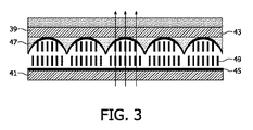
図2及び図3は、図1に示された装置に用いられることができる電気的に切替可能なレンズ素子35のアレイを示す。このアレイは、透過性ガラス基板39、41の対を有し、これら基板の接面にITOから形成される透過性電極43、45が設けられている。複製技術を用いて形成された逆レンズ構造47は前記基板39、41の間において、上方の基板39に隣接して設けられる。液晶材料49も前記基板39、41の間において、下方の基板41に隣接して設けられる。
2 and 3 show an array of electrically
前記逆レンズ構造47は、図2及び図3において断面図で示されるように、逆レンズ構造47と前記下方の基板41との間において、前記液晶材料49を平行な細長いレンズ形状にさせる。液晶材料と接している、前記逆レンズ構造47及び下方の基板41の面は、前記液晶材料を配向させるための配向層(図示せず)も備える。
2 and 3, the
図2は、前記電極43、45に電位が印加されていないときのアレイを示す。この状態において、前記液晶材料49の屈折率は、前記逆レンズアレイ47の屈折率よりも大幅に高く、これによりレンズ形状は、説明されるように、光出力誘導機能を提供する。
FIG. 2 shows the array when no potential is applied to the
図3は、前記電極43、45に約50から100Vの交流電位が印加されたときのアレイを示す。この状態において、前記液晶材料49の屈折率は、前記逆レンズアレイ47の屈折率と略同じであるため、説明されるように前記レンズ形状の光出力誘導機能はキャンセルされる。従って、この状態において前記アレイは"パススルー"モードで効果的に作用する。
FIG. 3 shows an array when an AC potential of about 50 to 100 V is applied to the
図1に示される表示装置での使用に適した切替可能なレンズ素子のアレイの構造及び動作のさらなる詳細は、米国特許番号US6,069,650号に見ることができる。 Further details of the structure and operation of an array of switchable lens elements suitable for use in the display device shown in FIG. 1 can be found in US Pat. No. 6,069,650.
図4は、上述したようなレンズ形式の結像装置の動作原理を示すと共に、バックライト50、例えばLCDのような表示装置54及びレンズアレイ58を示す。
FIG. 4 shows the operating principle of a lens-type imaging device as described above, and also shows a
本発明は、レンズ状(又は他の)レンズアレイ装置を前記表示パネルの上に取り付けることにも関する。 The invention also relates to mounting a lenticular (or other) lens array device on the display panel.
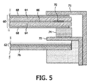
図5は、2Dモジュールの基本的な既知の設計を示す。 FIG. 5 shows the basic known design of the 2D module.
前記装置は、LCモジュール60、並びに基板76上の偏光子及び輝度上昇フォイルからなるスタック62を有する。
The apparatus has an
前記LCモジュールは、LC材料層66を挟み、2つの偏光子68が設けられる2つのガラス基板64を含んでいる。前記シールは70で示される。このLCモジュールは一般的に2mmぐらいの厚さを持つ。
The LC module includes two
表示モジュールはベースプレート72を持ち、ベゼル(bezel)71は2Dモジュールにおける機械的安定をもたらすのに使用され、スペーサーブロック/ダンピング素子74が前記スタック62に対するLCセルの取り付け位置を決めている。前記スペーサー74は、約2mm厚であり、LCパネルとスタック62との接面の間に結果生じる空間は約3.8mmである。
The display module has a
前記スタックは通例約0.9mm厚である。 The stack is typically about 0.9 mm thick.
前記バックライトは図5には示されていない。 The backlight is not shown in FIG.
3Dディスプレイを製造するためのある従来の方法は、完全な2Dディスプレイモジュールから始め、これを3Dディスプレイにアップデートすることである。 One conventional method for manufacturing a 3D display is to start with a complete 2D display module and update it to a 3D display.
この手法を用いて図5に示される構造を組み立てるために、以下のステップ、
−前記ベゼル71を取り除き、電子機器を取り外すことにより、2Dモジュールから2Dパネルを解体するステップ、
−前記2Dパネルを平坦なテーブルに置くステップ、
−エッジシールを用いて前記レンズアレイを貼り付け、3Dパネルを生じさせるステップ、
−前記レンズアレイと追加のガラスプレートとの間にある3Dパネルを圧搾することが可能であるように、前記3Dパネルの背後に追加のガラスプレートを挿入するステップ、及び
−本来の2Dモジュールに3Dパネルを組み立て、3Dモジュールを生じさせるステップ、
を実行する。
To assemble the structure shown in FIG. 5 using this technique, the following steps:
-Dismantling the 2D panel from the 2D module by removing the
-Placing the 2D panel on a flat table;
Applying the lens array with an edge seal to produce a 3D panel;
Inserting an additional glass plate behind the 3D panel so that it is possible to squeeze the 3D panel between the lens array and the additional glass plate, and 3D into the original 2D module. Assembling the panel to produce a 3D module;
Execute.
この製造処理で解消される多くの問題、
−前記ディスプレイの組み立て中及び解体中に電子機器が破損することがある、
−前記製造処理は非常に時間がかかり、面倒である、
−前記レンズは単にエッジ部で前記パネルに取り付けられているので、パネルプレート及びレンズ状レンズが湾曲しているので、性能を保証するのが非常に難しい、
−前記表示パネル自身は、完全に平坦ではなく、性能を保証することを非常に難しくさせる山及び谷を持っている、及び
−前記3Dパネルの背後にある追加のプレートに対する必要条件がシステムの重量を増大させると共に、前記システムの熱挙動を変化させ、性能の変化につながることがある、
問題がある。
Many problems solved by this manufacturing process,
-Electronic equipment may be damaged during assembly and disassembly of the display;
The manufacturing process is very time consuming and cumbersome,
The lens is simply attached to the panel at the edge, so the panel plate and lenticular lens are curved, making it very difficult to guarantee performance,
The display panel itself is not perfectly flat and has peaks and valleys that make it very difficult to guarantee performance, and the requirement for additional plates behind the 3D panel is the weight of the system And may change the thermal behavior of the system, leading to performance changes.
There's a problem.
この解体及び再組み立ての方法はこれにより多くの欠点を持つ。 This method of disassembly and reassembly thus has a number of drawbacks.
本発明は、標準的な2Dパネルが変更されることを未だ可能にして、これにより棚状表示モジュールを使用可能にする真空取付方法を提供するが、上述の問題の幾つかを取り扱っている。 Although the present invention provides a vacuum mounting method that still allows standard 2D panels to be changed, thereby enabling the use of a shelf display module, it addresses some of the problems discussed above.
図6は、本発明の組み立て方法を説明するフローチャートである。 FIG. 6 is a flowchart for explaining the assembly method of the present invention.
前記レンズシートは、クリーニング78により処理され、ステップ79において前記シートの表面にシールを貼り付ける。このシール線は、注入口を含み、完成品において表示領域を包囲するように、前記レンズシートのエッジ周りにある。前記シールは代わりに表示パネル面に貼り付けられてもよい。前記レンズアレイは通例2から5mm厚である。
The lens sheet is processed by cleaning 78 and a seal is applied to the surface of the sheet in
2Dディスプレイモジュールは、ステップ80において前記ベゼル71を前記2Dモジュールから取り除くことにより処理される。しかしながら、2枚パネルのディスプレイを取り除くこと、及びこれによりディスプレイの電子機器を切り離す必要は無い。
The 2D display module is processed in
ステップ82でのクリーニングの後、ステップ84において、前記レンズアレイは前記シール線に位置合わせされ、ステップ85において、2つのパネルは一緒に結合される。
After cleaning in
ステップ86において、前記レンズアレイ、シール線及び2Dパネルにより定められた空間に真空が印加される。
In
ステップ88において、前記注入口は閉じられ、ステップ90において、前記シールは硬化される。
In
この処理は、LCDパネル及びレンズプレートができるだけ密接して一緒に取り付けられることを可能にして、これは前記LCDパネル及びレンズプレートに対する許容誤差レベルに匹敵する、できるだけ小さい間隙を持つ。シール線を使用することは、前記処理が終了した後、前記プレートは動くことができないことを意味している。前記シール線は好ましくは、ガスケット(gasket)を形成するために硬化性の流体であり、前記シールはLCDパネル及びレンズプレートを一緒に結合するのに使用される。 This process allows the LCD panel and lens plate to be mounted together as closely as possible, which has as little gap as possible, comparable to the tolerance level for the LCD panel and lens plate. Using a seal line means that the plate cannot move after the process is finished. The seal line is preferably a curable fluid to form a gasket and the seal is used to bond the LCD panel and lens plate together.
LCDとレンズプレートとの間にある空隙の寸法を減少させるために真空が使用される。空隙内にある空気を排気することにより、この空隙の体積は減少する。 A vacuum is used to reduce the size of the air gap between the LCD and the lens plate. By exhausting the air in the gap, the volume of the gap is reduced.
好ましくは、前記シール線は加圧され、50から100μm厚の厚さになる。真空の印加は、LCDパネルとレンズプレートとの間の間隔が所望の間隔に達したときに終わる。この間隔は、表示領域の中心でより小さく、前記間隔が50−100μmに増大するシール線で最大となる。 Preferably, the seal line is pressurized to a thickness of 50 to 100 μm. The application of vacuum ends when the distance between the LCD panel and the lens plate reaches the desired distance. This spacing is smaller at the center of the display area and is greatest for seal lines where the spacing increases to 50-100 μm.
前記シール線は、水透過により硬化されることができ、さもなければ2つの成分のシール材が使用されることができ、硬化を行わせる温度及び/又はUVが利用される。 The seal line can be cured by water permeation, otherwise a two-component seal can be used, and a temperature and / or UV is used to effect curing.
結果として、両方のプレートは、非常に密接して一緒に取り付けられる。前記空隙内に真空が存在することは、前記プレートの固定を保つ必要は無く、固定処理ではなく位置合わせ処理の一部として使用される。 As a result, both plates are attached together very closely. The presence of a vacuum in the gap does not require the plate to remain fixed and is used as part of the alignment process rather than the fixing process.
この方法は、ディスプレイがもはや完全な分解を必要としないので、組み立て中及び解体中に電子機器への損傷を防ぐ。前記レンズアレイ及び前記パネルは、このレンズ−パネルの組み合わせの内側及び外側の圧力差により、このディスプレイのアクティブエリア全てにわたり密接して取り付けられ、これにより間隙の一様性を提供する。この方法は、更なるガラスプレートの必要性を防ぐ。 This method prevents damage to the electronics during assembly and disassembly because the display no longer requires complete disassembly. The lens array and the panel are intimately attached across the entire active area of the display due to the pressure difference inside and outside the lens-panel combination, thereby providing gap uniformity. This method prevents the need for additional glass plates.
ステップ92において前記シールを検査した後、追加のレンズアレイを嵌合するために、ステップ96で取り付けた前記ベゼル71がステップ94で再び用いられる。
After inspecting the seal in
最後に、保護プレートがステップ98において利用され、完成品がセットメーカーに供給される。
Finally, the protective plate is utilized in
図7は、図5と同じ参照番号を用いている、本発明の組み立てた装置を示す。前記レンズアレイは100で示され、前記シール線は102で示され、及び変更されたベゼルは71'で示される。 FIG. 7 shows the assembled device of the present invention using the same reference numbers as FIG. The lens array is shown as 100, the seal line is shown as 102, and the modified bezel is shown as 71 '.
上述したように、真空が印加された体積は、非常に小さな体積である。例えば、前記ディスプレイの大部分の領域にわたる間隙の寸法は、0から10μmの範囲にある。940×530mm2のシール線の内側の領域に対し、1μmの平均的な厚さは498mm3の真空含有体積を与える。 As described above, the volume to which the vacuum is applied is a very small volume. For example, the size of the gap across most areas of the display is in the range of 0 to 10 μm. For the area inside the 940 × 530 mm 2 seal line, an average thickness of 1 μm gives a vacuum containing volume of 498 mm 3 .
前記真空は、前記シール線の両側に圧力差を生じさせる。不完全なシールにとって、これは窒素、酸素及び他のガスが前記真空領域に浸透するための原動力として働く。結果として、真空のレベルは、前記シール材料の透過性に依存して、非常にゆっくりと減少する。 The vacuum creates a pressure difference on both sides of the seal line. For an imperfect seal, this serves as a driving force for nitrogen, oxygen and other gases to penetrate the vacuum region. As a result, the vacuum level decreases very slowly, depending on the permeability of the sealing material.
前記取り付けがシール線により機械的に固定されたとしても、この圧力変化は時間経過による間隔の僅かな変化、特にレンズアレイとパネルプレートとの間における間隙の増大を生じさせる。 Even if the attachment is mechanically secured by a seal line, this pressure change causes a slight change in the spacing over time, particularly an increase in the gap between the lens array and the panel plate.
図8を参照して説明された変更は、真空のレベルが前記透過性により減少する速度がかなり減少することを可能にする。結果として、レンズアレイと表示パネルプレートとの間にある間隙が増大する速度はかなり減少する。これは、前記製品の耐用年数の増大に寄与する。 The modification described with reference to FIG. 8 allows the rate at which the vacuum level is reduced by the permeability to be significantly reduced. As a result, the rate at which the gap between the lens array and the display panel plate increases is significantly reduced. This contributes to an increase in the service life of the product.
図8に示されるように、真空空間100の体積は、溝配列112により、シール線の長さを増大させることなく増大する。真空バッファを構成するこれら溝が考えられる。
As shown in FIG. 8, the volume of the
前記シール102により定められたシール線に隣接して、前記真空含有領域を広くする追加のバッファ空間が作られる。例えば、上で説明した498mm3の真空体積と比較して、溝の幅及び深さを1mmであると考えると、前記体積は2940mm3だけ増大することができる。これは約7倍に増えている。結果として、透過性ガスの影響はかなり減少する。
Adjacent to the seal line defined by the
上述した実施例は、例えば50μmから1000μmの範囲にある表示ピクセルのピッチを持つ液晶表示パネルを用いている。しかしながら、有機発光ダイオード(OLED)又は陰極線管(CRT)表示装置のような代替の型の表示パネルが用いられることは当業者には明らかである。 The above-described embodiment uses a liquid crystal display panel having a display pixel pitch in the range of 50 μm to 1000 μm, for example. However, it will be apparent to those skilled in the art that alternative types of display panels such as organic light emitting diodes (OLED) or cathode ray tube (CRT) displays are used.
前記表示装置及びレンズアレイを組み立てるのに使用される製造及び材料は普通であり、当業者によく知られているので、これらの詳細は説明しない。 Since the manufacture and materials used to assemble the display and lens array are common and well known to those skilled in the art, these details are not described.
様々な他の変更は当業者に明らかである。 Various other modifications will be apparent to those skilled in the art.
Claims (16)
立体画像を視察することを可能にするために、異なるピクセルからの出力を別々の空間位置に向けるための結像装置、
を有する裸眼立体視表示装置において、
前記表示パネル及び前記結像装置は、シール線の周りに一緒に結合され、前記表示パネル、前記結像装置及び前記シール線の間で定められる体積は、減少した圧力を持ち、前記表示パネル及び前記結像装置の少なくとも1つは、前記体積内において溝を備えており、前記溝は、前記定められる体積の残余の体積の2倍より大きい体積を有する裸眼立体視表示装置。 A display panel with an array of display pixels for display on a display, arranged in rows and columns, and to direct the output from different pixels to different spatial locations to allow viewing of a stereoscopic image Imaging device,
In an autostereoscopic display device having:
The display panel and the imaging device are coupled together around a seal line, and a volume defined between the display panel, the imaging device and the seal line has a reduced pressure, and the display panel and At least one of the imaging devices includes a groove in the volume, and the groove has a volume larger than twice the remaining volume of the defined volume .
−表示パネルを露出させるために、表示モジュールからベゼルを取り除くステップ、
−立体画像を視察することを可能にするために、異なるピクセルからの出力を別々の空間位置に向けるための結像装置を提供するステップ、
−2Dパネルの外部エッジ又は前記結像装置の外部エッジに、注入口を含む閉じたシール線を貼り付けるステップ、
−前記結像装置及び前記表示パネルをその間にある前記シール線と位置合わせするステップ、
−前記結像装置、前記シール線及び前記表示パネルの間で定められる体積の圧力を減少させるステップであり、これにより前記表示パネルと前記結像装置との接面の間にある間隙を減少させるステップ、並びに
−前記注入口を閉じて、前記シールを硬化させるステップ
を有する方法であって、当該方法は、前記表示パネル及び前記結像装置の少なくとも1つに前記体積内において溝を設けるステップを有し、前記溝は、前記体積の残余の体積の2倍より大きい体積を有する方法。 In a method of manufacturing an autostereoscopic display device,
-Removing the bezel from the display module to expose the display panel;
Providing an imaging device for directing the output from different pixels to different spatial positions in order to be able to inspect a stereoscopic image;
-Affixing a closed seal line including the inlet to the outer edge of the 2D panel or the outer edge of the imaging device;
Aligning the imaging device and the display panel with the seal line between them;
-Reducing the volume pressure defined between the imaging device, the seal line and the display panel, thereby reducing the gap between the contact surface of the display panel and the imaging device. step, and - closing the inlet, a method of have a step of curing the sealing, the method is provided with a groove in the display panel and the inside volume to at least one of the imaging device step And the groove has a volume greater than twice the remaining volume of the volume .
Applications Claiming Priority (3)
| Application Number | Priority Date | Filing Date | Title |
|---|---|---|---|
| US82276306P | 2006-08-18 | 2006-08-18 | |
| US60/822,763 | 2006-08-18 | ||
| PCT/IB2007/053277 WO2008020417A2 (en) | 2006-08-18 | 2007-08-17 | Autostereoscopic display device and method of manufacturing the same |
Publications (3)
| Publication Number | Publication Date |
|---|---|
| JP2010501880A JP2010501880A (en) | 2010-01-21 |
| JP2010501880A5 JP2010501880A5 (en) | 2013-02-14 |
| JP5366806B2 true JP5366806B2 (en) | 2013-12-11 |
Family
ID=39082435
Family Applications (1)
| Application Number | Title | Priority Date | Filing Date |
|---|---|---|---|
| JP2009524301A Expired - Fee Related JP5366806B2 (en) | 2006-08-18 | 2007-08-17 | Autostereoscopic display device and method for manufacturing the same |
Country Status (4)
| Country | Link |
|---|---|
| EP (1) | EP2057500A2 (en) |
| JP (1) | JP5366806B2 (en) |
| CN (1) | CN101506716B (en) |
| WO (1) | WO2008020417A2 (en) |
Families Citing this family (4)
| Publication number | Priority date | Publication date | Assignee | Title |
|---|---|---|---|---|
| TWI497561B (en) * | 2011-06-16 | 2015-08-21 | Au Optronics Corp | Device and method for vacuuming a display panel |
| KR101930298B1 (en) * | 2011-09-22 | 2018-12-18 | 엘지디스플레이 주식회사 | Stereoscopic image display apparatus |
| CN104977773B (en) * | 2015-07-13 | 2019-08-16 | 张家港康得新光电材料有限公司 | Surface floating type liquid crystal column lens array device, manufacturing method and display device |
| US10455225B2 (en) * | 2017-05-12 | 2019-10-22 | Pure Depth Limited | Multi-layered display with interstitial layer air filter |
Family Cites Families (6)
| Publication number | Priority date | Publication date | Assignee | Title |
|---|---|---|---|---|
| CN1336562A (en) * | 2000-07-28 | 2002-02-20 | 张越苏 | Stereo virtual image display method and display |
| TWI223551B (en) * | 2001-10-19 | 2004-11-01 | Vrex Inc | Method and apparatus for easy attachment and alignment of 3D stereoscopic enabling devices |
| JP2005535000A (en) * | 2002-09-03 | 2005-11-17 | イクスドライデー テヒノロギーズ ゲーエムベーハー | Device for 3D display of landscape / object |
| JP4293013B2 (en) * | 2003-02-28 | 2009-07-08 | 日本電気株式会社 | Image display device and manufacturing method thereof |
| DE10316733A1 (en) * | 2003-04-08 | 2004-10-28 | X3D Technologies Gmbh | Process for converting a 2D screen to an autostereoscopic screen and adapter frame |
| US7924351B2 (en) * | 2006-02-24 | 2011-04-12 | Koninklijke Philips Electronics N.V. | Autostereoscopic display |
-
2007
- 2007-08-17 CN CN2007800307658A patent/CN101506716B/en not_active Expired - Fee Related
- 2007-08-17 EP EP07805430A patent/EP2057500A2/en not_active Withdrawn
- 2007-08-17 WO PCT/IB2007/053277 patent/WO2008020417A2/en active Application Filing
- 2007-08-17 JP JP2009524301A patent/JP5366806B2/en not_active Expired - Fee Related
Also Published As
| Publication number | Publication date |
|---|---|
| CN101506716A (en) | 2009-08-12 |
| WO2008020417A2 (en) | 2008-02-21 |
| EP2057500A2 (en) | 2009-05-13 |
| CN101506716B (en) | 2012-11-07 |
| WO2008020417A3 (en) | 2008-10-30 |
| JP2010501880A (en) | 2010-01-21 |
Similar Documents
| Publication | Publication Date | Title |
|---|---|---|
| KR101555892B1 (en) | Auto-stereoscopic display device | |
| JP5301283B2 (en) | Display device | |
| US7365809B2 (en) | Stereoscopic image display device having negative pressure regions within | |
| JP5039055B2 (en) | Switchable autostereoscopic display device | |
| JP5384113B2 (en) | Autostereoscopic display device | |
| JP5630144B2 (en) | Light barrier element and display device | |
| JP2008191325A (en) | Display device | |
| JP5925205B2 (en) | Optical beam deflecting device and multi-view display | |
| KR20100131449A (en) | Autostereoscopic image output device | |
| KR101157425B1 (en) | Large size display device of tiled method | |
| JP2009175600A (en) | Liquid crystal panel and liquid crystal display device | |
| JP5366806B2 (en) | Autostereoscopic display device and method for manufacturing the same | |
| JP2010501880A5 (en) | ||
| CN108370439B (en) | Display apparatus and display control method | |
| US9606367B2 (en) | Stereoscopic display device | |
| CA2860677A1 (en) | Lenticular means for an autostereoscopic display apparatus having an electro -optic and an orientation layer and method of manufacturing the same | |
| JP4595287B2 (en) | 3D image display device | |
| JP2009157301A (en) | Electro-optical device | |
| CN102449539A (en) | Liquid chrystal display device with focusing arrangement | |
| JP2013178441A (en) | Liquid crystal barrier, display device and electronic apparatus | |
| JP2013187758A (en) | Liquid crystal barrier, display device, and electronic apparatus | |
| JP2010044206A (en) | Display device | |
| JP2009145698A (en) | Display device | |
| JP2008139793A (en) | Display device | |
| JP2009047759A (en) | Display device |
Legal Events
| Date | Code | Title | Description |
|---|---|---|---|
| A621 | Written request for application examination |
Free format text: JAPANESE INTERMEDIATE CODE: A621 Effective date: 20100813 |
|
| A977 | Report on retrieval |
Free format text: JAPANESE INTERMEDIATE CODE: A971007 Effective date: 20120626 |
|
| A131 | Notification of reasons for refusal |
Free format text: JAPANESE INTERMEDIATE CODE: A131 Effective date: 20120703 |
|
| A601 | Written request for extension of time |
Free format text: JAPANESE INTERMEDIATE CODE: A601 Effective date: 20121002 |
|
| A602 | Written permission of extension of time |
Free format text: JAPANESE INTERMEDIATE CODE: A602 Effective date: 20121010 |
|
| A524 | Written submission of copy of amendment under article 19 pct |
Free format text: JAPANESE INTERMEDIATE CODE: A524 Effective date: 20121221 |
|
| TRDD | Decision of grant or rejection written | ||
| A01 | Written decision to grant a patent or to grant a registration (utility model) |
Free format text: JAPANESE INTERMEDIATE CODE: A01 Effective date: 20130813 |
|
| A61 | First payment of annual fees (during grant procedure) |
Free format text: JAPANESE INTERMEDIATE CODE: A61 Effective date: 20130910 |
|
| R150 | Certificate of patent or registration of utility model |
Free format text: JAPANESE INTERMEDIATE CODE: R150 |
|
| LAPS | Cancellation because of no payment of annual fees |