JP5365849B2 - Electric power steering device - Google Patents
Electric power steering device Download PDFInfo
- Publication number
- JP5365849B2 JP5365849B2 JP2009102128A JP2009102128A JP5365849B2 JP 5365849 B2 JP5365849 B2 JP 5365849B2 JP 2009102128 A JP2009102128 A JP 2009102128A JP 2009102128 A JP2009102128 A JP 2009102128A JP 5365849 B2 JP5365849 B2 JP 5365849B2
- Authority
- JP
- Japan
- Prior art keywords
- housing
- sensor
- cylinder
- steering
- torque sensor
- Prior art date
- Legal status (The legal status is an assumption and is not a legal conclusion. Google has not performed a legal analysis and makes no representation as to the accuracy of the status listed.)
- Expired - Fee Related
Links
Images


Classifications
-
- B—PERFORMING OPERATIONS; TRANSPORTING
- B62—LAND VEHICLES FOR TRAVELLING OTHERWISE THAN ON RAILS
- B62D—MOTOR VEHICLES; TRAILERS
- B62D5/00—Power-assisted or power-driven steering
- B62D5/04—Power-assisted or power-driven steering electrical, e.g. using an electric servo-motor connected to, or forming part of, the steering gear
- B62D5/0409—Electric motor acting on the steering column
-
- B—PERFORMING OPERATIONS; TRANSPORTING
- B62—LAND VEHICLES FOR TRAVELLING OTHERWISE THAN ON RAILS
- B62D—MOTOR VEHICLES; TRAILERS
- B62D6/00—Arrangements for automatically controlling steering depending on driving conditions sensed and responded to, e.g. control circuits
- B62D6/08—Arrangements for automatically controlling steering depending on driving conditions sensed and responded to, e.g. control circuits responsive only to driver input torque
- B62D6/10—Arrangements for automatically controlling steering depending on driving conditions sensed and responded to, e.g. control circuits responsive only to driver input torque characterised by means for sensing or determining torque
Landscapes
- Engineering & Computer Science (AREA)
- Chemical & Material Sciences (AREA)
- Combustion & Propulsion (AREA)
- Transportation (AREA)
- Mechanical Engineering (AREA)
- Power Steering Mechanism (AREA)
Abstract
Description
本発明は、電動パワーステアリング装置に関する。 The present invention relates to an electric power steering apparatus.
電動パワーステアリング装置は、操舵補助機構として、操舵トルクを検出するトルクセンサと、操舵補助力を発生させる電動モータと、電動モータの出力回転を減速する減速機構とを有している(例えば、特許文献1参照。)。
特許文献1では、ステアリングシャフトを回転可能に支持するコラムチューブと、トルクセンサを収容するセンサハウジングと、減速機構を収容するギヤハウジングとを、互いに別体で形成することが提案されている。
The electric power steering apparatus includes, as a steering assist mechanism, a torque sensor that detects steering torque, an electric motor that generates a steering assist force, and a speed reduction mechanism that decelerates the output rotation of the electric motor (for example, a patent). Reference 1).
Patent Document 1 proposes that a column tube that rotatably supports a steering shaft, a sensor housing that houses a torque sensor, and a gear housing that houses a speed reduction mechanism are formed separately from each other.
しかし、特許文献1では、コラムチューブとセンサハウジングとが互いに別体で形成されているので、部品点数が多くなる。その結果、製造コストが高くなる。
また、電動パワーステアリング装置は、車両の限られたスペースに配置されるため、ステアリングシャフトの軸方向に関して小型化の要請がある。
そこで、この発明の目的は、安価で小型の電動パワーステアリング装置を提供することである。
However, in Patent Document 1, since the column tube and the sensor housing are formed separately from each other, the number of parts increases. As a result, the manufacturing cost increases.
Further, since the electric power steering device is disposed in a limited space of the vehicle, there is a demand for miniaturization in the axial direction of the steering shaft.
An object of the present invention is to provide an inexpensive and small electric power steering device.
上記の目的を達成するための請求項1記載の発明は、操舵部材(2)に連結されたステアリングシャフト(3)を回転可能に支持し、車体(12)に保持されるコラムチューブ(31)と、上記コラムチューブの下部を拡径して構成された筒状のセンサハウジング(34)と、上記センサハウジング内に収容され、操舵トルクを検出するトルクセンサ(20)と、操舵補助用の電動モータ(23)の回転を上記ステアリングシャフトに伝達する、ウォーム(26)およびウォームホイール(27)を含む減速機構(24)と、上記減速機構を収容するギヤハウジング(32)と、上記ウォームホイールを挟んだ上下に配置され、上記ステアリングシャフトを回転可能に支持する上軸受(40)および下軸受(41)と、を備え、上記ギヤハウジングは、上記下軸受を介して上記ステアリングシャフトを回転可能に支持する筒状の下ハウジング(37)と、上ハウジング(36)とを含み、上記上ハウジングは、内筒(67)と、外筒(68)と、上記内筒および上記外筒間を連結する環状の連結壁(69)とを有し、上記外筒が、上記下ハウジングの上部(64)の内周(65)に圧入され、上記内筒が、上記上軸受を介して上記ステアリングシャフトを回転可能に支持し、上記センサハウジングは、上記トルクセンサが嵌合された内周(90)を有する第1の筒部(341)と、上記コラムチューブの下端部(77)に設けられ上記第1の筒部よりも大径の第2の筒部(342)とを含み、上記第2の筒部の内周(94)に、上記上ハウジングの上記内筒が圧入され、これにより、上記内筒が縮径していることを特徴とする電動パワーステアリング装置(1)である。
In order to achieve the above object, the invention as set forth in claim 1 is a column tube (31) which rotatably supports a steering shaft (3) connected to a steering member (2) and is held by a vehicle body (12). A cylindrical sensor housing (34) configured to expand the diameter of the lower portion of the column tube, a torque sensor (20) that is housed in the sensor housing and detects steering torque, and a steering assist electric motor A speed reduction mechanism (24) including a worm (26) and a worm wheel (27) for transmitting rotation of the motor (23) to the steering shaft, a gear housing (32) for housing the speed reduction mechanism, and the worm wheel An upper bearing (40) and a lower bearing (41), which are arranged above and below and rotatably support the steering shaft, The ring includes a cylindrical lower housing (37) that rotatably supports the steering shaft via the lower bearing, and an upper housing (36). The upper housing includes an inner cylinder (67), an outer cylinder (67), and an outer cylinder (67). A cylinder (68) and an annular connecting wall (69) for connecting the inner cylinder and the outer cylinder, and the outer cylinder is press-fitted into the inner periphery (65) of the upper part (64) of the lower housing. The inner cylinder rotatably supports the steering shaft via the upper bearing, and the sensor housing has a first cylinder portion (341) having an inner periphery (90) fitted with the torque sensor. ) And a second cylinder part (342) provided at the lower end part (77) of the column tube and having a larger diameter than the first cylinder part, and an inner periphery (94) of the second cylinder part to, the inner cylinder of the upper housing is press-fitted, thereby It is an electric power steering device (1), characterized in that the inner tube is reduced in diameter.
請求項2記載の発明は、請求項1において、上記トルクセンサは、上記センサハウジングの上記第1の筒部の上記内周に嵌合した環状の本体(81)を含み、上記トルクセンサの上記本体と上記上ハウジングの上記内筒との間に介在し、弾性的に圧縮された弾性部材(96)によって、上記トルクセンサの上記本体が、上記センサハウジングの上記内周に設けられた受け部(91)に押圧され、その結果、上記トルクセンサの上記本体が上記センサハウジングの軸方向(A2)に位置決めされていることを特徴とする電動パワーステアリング装置である。 According to a second aspect of the present invention, in the first aspect, the torque sensor includes an annular main body (81) fitted to the inner periphery of the first cylindrical portion of the sensor housing, and the torque sensor is configured as described above. An elastic member (96) interposed between the main body and the inner cylinder of the upper housing and elastically compressed, the receiving portion provided on the inner periphery of the sensor housing, the main body of the torque sensor (91), and as a result, the main body of the torque sensor is positioned in the axial direction (A2) of the sensor housing.
請求項3記載の発明は、請求項1または2において、上記上ハウジングは、上記センサハウジングの上記軸方向に関して、上記ウォームの周面(260)に対向する第1の対向部(71)と、上記ウォームホイールの端面(270)に対向する第2の対向部(72)とを含み、上記第1の対向部に、上記ウォームから逃げる逃げ部(73,74)が設けられていることを特徴とする電動パワーステアリング装置である。 According to a third aspect of the present invention, in the first or second aspect, the upper housing includes a first facing portion (71) facing the peripheral surface (260) of the worm with respect to the axial direction of the sensor housing; And a second facing portion (72) facing the end face (270) of the worm wheel, wherein the first facing portion is provided with escape portions (73, 74) for escaping from the worm. This is an electric power steering device.
なお、上記括弧内の英数字は、後述の実施形態における対応構成要素の参照符号を示すものであるが、これらの参照符号により特許請求の範囲を限定する趣旨ではない。 In addition, although the alphanumeric characters in the parentheses indicate reference signs of corresponding components in the embodiments described later, the scope of the claims is not limited by these reference signs.
請求項1記載の発明によれば、センサハウジングが、コラムチューブの下部を拡径することにより構成されているので、センサハウジングとコラムチューブとを一体化できる。その結果、部品点数を削減でき、製造コストを低減できる。これに加えて、センサハウジングの第2の筒部を第1の筒部よりも大径にしたので、第2の筒部と上ハウジングの内筒との接触面積を確保しつつ、センサハウジングの軸方向に関して第2の筒部を短くすることができる。従って、安価でステアリングシャフトの軸方向に関して小型の電動パワーステアリング装置を実現することができる。 According to the first aspect of the present invention, since the sensor housing is configured by expanding the diameter of the lower part of the column tube, the sensor housing and the column tube can be integrated. As a result, the number of parts can be reduced and the manufacturing cost can be reduced. In addition, since the second cylindrical portion of the sensor housing has a larger diameter than the first cylindrical portion, the contact area between the second cylindrical portion and the inner cylinder of the upper housing is ensured while the sensor housing The second cylindrical portion can be shortened with respect to the axial direction. Therefore, it is possible to realize an electric power steering device that is inexpensive and small in the axial direction of the steering shaft.
請求項2記載の発明によれば、部品の寸法誤差を吸収しつつ、トルクセンサの本体を受け部に高精度に位置決めでき、ひいては、製造コストをより一層低減できる。
請求項3の発明によれば、逃げ部によって、ウォームの周面と第1の対向部との干渉の発生を防止しつつ、ウォームホイールの端面と第2の対向部との距離を短くすることができる。ステアリングシャフトの軸方向に関してより一層小型の電動パワーステアリング装置を実現することができる。
According to the second aspect of the present invention, it is possible to position the torque sensor main body on the receiving portion with high accuracy while absorbing the dimensional error of the parts, thereby further reducing the manufacturing cost.
According to the invention of
以下では、この発明の実施の形態を、添付図面を参照して詳細に説明する。
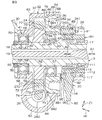
図1は、本発明の一実施の形態の電動パワーステアリング装置の概略構成の模式図である。図1を参照して、電動パワーステアリング装置(EPS:Electric Power Steering System)1は、ステアリングホイール等の操舵部材2に連結しているステアリングシャフト3と、ステアリングシャフト3に自在継手4を介して連結された中間軸5と、中間軸5に自在継手6を介して連結されたピニオン軸7と、ピニオン軸7の端部近傍に設けられたピニオン8に噛み合うラック9を有して自動車の左右方向に延びる転舵軸としてのラック軸10とを有している。
Hereinafter, embodiments of the present invention will be described in detail with reference to the accompanying drawings.
FIG. 1 is a schematic diagram of a schematic configuration of an electric power steering apparatus according to an embodiment of the present invention. Referring to FIG. 1, an electric power steering system (EPS) 1 is connected to a
ピニオン軸7およびラック軸10を含むラックアンドピニオン機構によって、操舵機構11が構成されている。ラック軸10は、車体12に固定されるラックハウジング13内に図示しない複数の軸受を介して直線往復可能に支持されている。ラック軸10には、一対のタイロッド14が結合されている。各タイロッド14は対応するナックルアーム15を介して対応する転舵輪16に連結されている。
A
操舵部材2が操作されてステアリングシャフト3が回転されると、その回転がピニオン8およびラック9によって、自動車の左右方向に沿ってのラック軸10の直線運動に変換される。これにより、転舵輪16の転舵が達成される。
ステアリングシャフト3は、操舵部材2に連なる入力軸17と、ピニオン軸7に連なる出力軸18とに分割されている。これら入力軸17および出力軸18はトーションバー19を介して同一の軸線上で互いに連結されている。入力軸17に操舵トルクが入力されたときに、トーションバー19が弾性ねじり変形し、これにより、入力軸17および出力軸18が相対回転するようになっている。
When the steering member 2 is operated and the
The
トーションバー19を介する入力軸17および出力軸18の間の相対回転変位量により操舵トルクを検出するトルクセンサ20が設けられている。また、車速を検出するための車速センサ21が設けられている。また、制御装置としてのECU(Electronic Control Unit :電子制御ユニット)22が設けられている。また、操舵補助力を発生させるための電動モータ23と、この電動モータ23の出力回転を減速する減速機構24とが設けられている。
A
トルクセンサ20および車速センサ21からの検出信号が、ECU22に入力されるようになっている。ECU22は、トルク検出結果や車速検出結果等に基づいて、操舵補助用の電動モータ23を制御する。電動モータ23の出力回転が減速機構24を介して減速されてピニオン軸7に伝達され、ラック軸10の直線運動に変換されて、操舵が補助されるようになっている。
Detection signals from the
減速機構24は、操舵補助用の電動モータ23の出力回転をステアリングシャフト3の出力軸18に伝達する。減速機構24は、駆動ギヤとしてのウォーム26と、このウォーム26に噛み合う従動ギヤとしてのウォームホイール27とを備えている。
ウォーム26は、電動モータ23の出力軸(図示せず)と同心に配置されており、電動モータ23により回転駆動される。
The
The
ウォームホイール27は、ステアリングシャフト3の出力軸18に同行回転し且つステアリングシャフト3の軸方向A1(以下、単に軸方向A1ともいう。)に移動不能に連結されている。
また、電動パワーステアリング装置1は、ステアリングシャフト3を回転可能に支持するステアリングコラム28を有している。ステアリングコラム28は、第1および第2のブラケット29,30を介して、車体12に支持されている。
The
The electric power steering apparatus 1 has a
図2は、図1の電動パワーステアリング装置1の要部の断面図である。図2を参照して、ステアリングコラム28は、軸方向A1に平行に延びており、また、車両の前後方向H1に対して傾斜する方向に延びている。例えば、操舵部材2が上側となるように、ステアリングシャフト3の中心軸線が前後方向H1に対して斜めに配置されている。なお、図2および図3には、上下方向Z1を図示してある。
FIG. 2 is a cross-sectional view of a main part of the electric power steering apparatus 1 of FIG. Referring to FIG. 2, the
ステアリングコラム28は、ステアリングシャフト3の一部を収容するコラムチューブ31と、減速機構24を収容するギヤハウジング32とを有している。コラムチューブ31とギヤハウジング32とは、互いに別体で形成され、互いに連結されている。
コラムチューブ31は、軸方向A1に関するステアリングコラム28の上部および中間部を構成している。コラムチューブ31は、金属、例えば、鋼により形成されている。コラムチューブ31は、ステアリングシャフト3を回転可能に支持している。コラムチューブ31は、車体12に第1のブラケット29を介して保持され、具体的には、固定されている。
The
The
コラムチューブ31は、軸方向A1に関する当該コラムチューブ31の上部33と、軸方向A1に関する当該コラムチューブ31の下部としてのセンサハウジング34とを有している。上部33と、センサハウジング34とは、単一の材料により一体に形成されている。
コラムチューブ31の上部33は、軸方向A1に真直に延びる筒状をなしている。
The
The
センサハウジング34は、上部33よりも大径に形成されており、トルクセンサ20の一部を収容している。センサハウジング34は、筒状をなしており、コラムチューブ31の下部を塑性変形を伴って拡径させることによって構成されている。
センサハウジング34は、軸方向A1に関する当該センサハウジング34の上部を構成し相対的に小径の第1の筒部341と、軸方向A1に関する当該センサハウジング34の下部を構成し第1の筒部341よりも大径の第2の筒部342と、第1の筒部341および第2の筒部342を互いに接続する接続部343とを含んでいる。第1の筒部341と第2の筒部342と接続部343とは、互いに一体に単一材料により形成されている。
The
The
第1の筒部341は、トルクセンサ20を保持している。第2の筒部342は、コラムチューブ31の下端部に形成されており、ギヤハウジング32に連結されている。
ギヤハウジング32は、軸方向A1に関するステアリングコラム28の下部を構成している。ギヤハウジング32は、車体12に第2のブラケット30を介して支持されている。ギヤハウジング32は、電動モータ23を支持している。
The
The
ギヤハウジング32は、上ハウジング36および下ハウジング37を有している。上ハウジング36および下ハウジング37は、互いに別体で形成され、互いに嵌め合わされている。上ハウジング36および下ハウジング37のそれぞれは、金属、例えば、アルミニウム合金により形成されている。
図1を参照して、電動パワーステアリング装置1は、ステアリングシャフト3の入力軸17の軸方向上部を回転可能に支持する軸受39を有している。この軸受39は、ステアリングコラム28のコラムチューブ31の上端部に保持されている。
The
Referring to FIG. 1, the electric power steering apparatus 1 includes a bearing 39 that rotatably supports an upper portion in the axial direction of the
また、電動パワーステアリング装置1は、ステアリングシャフト3の出力軸18を支持する上軸受40および下軸受41を有している。
上軸受40および下軸受41は、軸方向A1に関してウォームホイール27を挟んだ両側に配置されている。上軸受40は、軸方向A1に関して相対的に上方に配置されており、上ハウジング36に保持されている。下軸受41は、軸方向A1に関して相対的に下方に配置されており、下ハウジング37に保持されている。
Further, the electric power steering apparatus 1 includes an
The
図2を参照して、上軸受40および下軸受41は、ステアリングシャフト3の入力軸17を、出力軸18およびトーションバー19を介して回転可能に支持している。
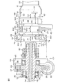
図3は、図2の要部の拡大図である。図3を参照して、上軸受40および下軸受41は、転がり軸受であり、また密封軸受としてのシール軸受である。上軸受40は、内輪43と、外輪44と、転動体としての複数の玉45とを有している。下軸受41は、内輪47と、外輪48と、転動体としての複数の玉49とを有している。
Referring to FIG. 2, the
FIG. 3 is an enlarged view of a main part of FIG. With reference to FIG. 3, the
出力軸18は、上軸受40の内輪43が嵌合している第1の嵌合部51と、ウォームホイール27が嵌合している第2の嵌合部52と、下軸受41の内輪47が嵌合している第3の嵌合部53と、第2および第3の嵌合部52,53を互いに接続する段部54と、第3の嵌合部53に隣接する雄ねじ部55とを有している。雄ねじ部55には、ナット56がねじ嵌合している。
The
第1の嵌合部51が、上軸受40の内輪43の内周に、締まりばめにより嵌合されている。上軸受40の内輪43の下端面が、ウォームホイール27の上端面に当接している。第2の嵌合部52が、ウォームホイール27の中央孔に圧入されている。これにより、第2の嵌合部52とウォームホイール27とが互いに固定されている。出力軸18の段部54とナット56との間に、下軸受41の内輪47が挟持されている。下軸受41の内輪47の内周に、第3の嵌合部53が、締まりばめにより嵌合されている。
The first
軸方向A1に関する下ハウジング37の下部は、下軸受41を保持する軸受保持孔58と、この軸受保持孔58に隣接した環状の段部59とを有している。下ハウジング37の下端面60には、第2のブラケット30が固定されている。下軸受41の外輪48は、下ハウジング37の軸受保持孔58に嵌合された状態で、段部59および第2のブラケット30との間に挟持されることで、ギヤハウジング32に対する軸方向A1の両方向への外輪48の移動が規制されている。
A lower portion of the
軸方向A1に関する下ハウジング37の上部は、ウォーム26を収容するための第1の筒状部分62と、ウォームホイール27を収容するための第2の筒状部分63と、上ハウジング36と連結するための筒状の連結部64とを有している。連結部64は、内周65と、軸方向A1に直交する環状平面からなる位置決め面66とを有している。
なお、図2および図3において、第1の筒状部分62の中心軸線は、紙面垂直方向に延びている。また、第2の筒状部分63と、連結部64と、ステアリングシャフト3とは、互いに同心に配置されている。
The upper part of the
2 and 3, the central axis of the first
上ハウジング36は、内筒67と、外筒68と、内筒67および外筒68間を連結する環状の連結壁69とを含んでいる。上ハウジング36は、全体として環状をなしている。なお、以下、上ハウジング36に関する説明においては、上ハウジング36の周方向および径方向を、単に周方向、径方向ともいう。
内筒67および外筒68は、互いに同心に配置されている。外筒68が、下ハウジング37の上部の連結部64の内周65に圧入されている。また、内筒67が、センサハウジング34の第2の筒部342の内周94に圧入されている。外筒68の外周681は、当該外筒68の圧入を案内するための面取り部682を有している。
The
The
内筒67と外筒68とはともに、連結壁69から軸方向A1に関して上側に向けて延びている。これにより、下ハウジング37の連結部64および上ハウジング36の外筒68の互いの嵌合部の少なくとも一部と、上ハウジング36の内筒67およびセンサハウジング34の第2の筒部342の互いの嵌合部の少なくとも一部とが、軸方向A1に互いに重なり合っているので、軸方向A1に互いにずれる場合と比較して、電動パワーステアリング装置1を軸方向A1に短くできる。
Both the
図4は、図3に示すA4部の拡大図である。図3および図4を参照して、上ハウジング36は、センサハウジング34の軸方向A2に沿ってウォーム26の周面260に対向する第1の対向部71と、上述の軸方向A2に沿ってウォームホイール27の端面270に対向する第2の対向部72とを有している。第1の対向部71は、ウォーム26との干渉を回避するための第1および第2の逃げ部73,74を有している。
FIG. 4 is an enlarged view of a portion A4 shown in FIG. 3 and 4, the
第1および第2の対向部71,72は、軸方向A1に関する上ハウジング36の下側の端面75に配置されている。第1の対向部71は、第2の対向部72よりも径方向の外方において、周方向の一部に配置されている。第2の対向部72は、軸方向A1に対して直交する環状平面により形成されている。
第1および第2の逃げ部73,74は、軸方向A1に関して第2の対向部72よりも窪んでいる。第1の逃げ部73は、相対的に径方向の内方に配置され、第2の逃げ部74は、相対的に径方向の外方に配置されている。
The first and second facing
The first and
第1の逃げ部73は、円錐面の一部により形成されている。従って、形成が容易である。第1の逃げ部73は、第2の対向部72に対して傾斜するとともに、軸方向A1に対してテーパ状に傾斜している。
第2の逃げ部74は、軸方向A1に対して垂直に形成され、軸方向A1に関して第1の逃げ部73よりも窪んでいる。第2の逃げ部74は、環状平面の一部により形成されている。従って、第2の逃げ部74の形成が容易である。
The
The
図3を参照して、上ハウジング36の端面75には、位置決め面76が形成されている。位置決め面76は、下ハウジング37の連結部64の位置決め面66と当接することにより、上ハウジング36と下ハウジング37とを軸方向A1に互いに位置決めする。
位置決め面76と第2の逃げ部74とは、周方向に並んでおり、全体として、単一の環状平面を形成している。これにより、第2の逃げ部74と位置決め面76とを形成するための手間を削減できる。
Referring to FIG. 3, a
The
第2の逃げ部74と位置決め面76とにより形成された環状平面において、周方向に関する環状平面の一部が、第2の逃げ部74を構成し、環状平面の残りの部分が、位置決め面76を構成している。
上ハウジング36の内筒67が、上軸受40を介してステアリングシャフト3を回転可能に支持している。具体的には、内筒67が、センサハウジング34の第2の筒部342の内周94に圧入されることにより、内筒67が縮径されている。その結果、上軸受40の外輪44が内筒67によって、径方向隙間がない状態(タイトフィット)で保持されている。また、センサハウジング34の第2の筒部342の下端77が、連結壁69の環状平面691に当接している。
In the annular plane formed by the
An
図5は、図3に示す要部の分解図である。図3および図5を参照して、電動パワーステアリング装置1は、操舵トルクを検出するために、上述の入力軸17と、出力軸18と、トーションバー19と、トルクセンサ20と、磁気回路形成部材80とを有している。磁気回路形成部材80は、環状の永久磁石111と、軟磁性体としての環状の第1および第2の磁気ヨーク112,113とを有している。トルクセンサ20は、磁気回路形成部材80に生じた磁束に基づいて操舵トルクを検出するようになっている。
FIG. 5 is an exploded view of the main part shown in FIG. With reference to FIGS. 3 and 5, the electric power steering apparatus 1 detects the steering torque so that the
トルクセンサ20は、磁気回路形成部材80に生じた磁束を集める軟磁性体としての環状の第1および第2の集磁リング117,118と、集められた磁束の密度に基づいて操舵トルクを検出するホールICを含む磁気センサ(図示せず)と、これらを保持する合成樹脂製の環状の本体81と、この本体81から延びる配線82とを有している。
本体81は、外周83と、軸方向A1に関する両側に形成された端面84,85とを有している。配線82は、本体81の外周83の一部から径方向外方へ延びている。本体81の外周83は、円筒面により形成された円筒部分831と、この円筒部分831よりも径方向外方に突出する複数の突起832と、面取り部833とを含んでいる。
The
The
面取り部833は、円筒部分831と端面85とを接続しており、センサハウジング34への本体81の嵌合を案内し、例えば圧入するときのかじりの発生を抑制する。
円筒部分831の直径は、センサハウジング34の第1の筒部341の内周90の内径と等しい値よりもわずかに小さい値にされている。
複数の突起832は、センサハウジング34の周方向に互いに離隔して配置されている。各突起832は、第1の筒部341の内周90に当接し、径方向に圧縮されている。これにより、トルクセンサ20の本体81を、センサハウジング34の内周90に、小さな締めしろで、且つ軽い力で圧入させることができる。
The chamfered
The diameter of the
The plurality of
センサハウジング34の第1の筒部341は、内周90を有している。第1の筒部341の内周90に、トルクセンサ20の本体81が嵌合されている。内周90には、受け部としての複数の突起91が形成されている。各突起91は、内周90から径方向内方に突出している。複数の突起91は、センサハウジング34の周方向(ステアリングシャフト3の周方向B1に一致する。)に関して互いに離隔して、例えば、均等に配置されている。なお、突起91は、図示の都合で均等に図示されていない。また、突起91は、少なくとも1箇所に配置されていればよい。本実施形態では、突起91が2箇所に設けられている場合に則して説明する。
The
2つの突起91は、センサハウジング34の軸方向A2(軸方向A2は、ステアリングシャフト3の軸方向A1と一致する。)に関して、同じ位置に配置されており、センサハウジング34の下端77から所定距離を離隔している。
なお、受け部としては、図示しないが、内周90に設けられた段部であってもよい。また、受け部としては、内周90に単一材料で一体に形成されていてもよいし、内周90に固定されていてもよい。
The two
In addition, as a receiving part, although not shown in figure, the step part provided in the
また、センサハウジング34には、単一の挿通孔92が形成されている。挿通孔92は、第1の筒部341、第2の筒部342、および接続部343にまたがって形成されている。挿通孔92には、トルクセンサ20の配線82がセンサハウジング34の外部に挿通されている。
センサハウジング34の第1の筒部341を鋼により形成したので、アルミニウム合金により形成した場合と比較して、材料コストを低減できる。これに加えて、トルクセンサ20の耐磁界性を向上させることができる。すなわち、外部からのノイズがトルクセンサ20へ及ぼす影響を抑制できる。ひいては、トルクセンサ20において、磁気シールドするためのシールド板を廃止したり、簡素化したりすることができる。
In addition, a
Since the first
接続部343は、軸方向A1に対して傾斜したテーパ形状をなしており、第1の筒部341へのトルクセンサ20の本体81の嵌合を案内する。
第2の筒部342は、コラムチューブ31の下端部に配置されており、環状をなし、開口93を有している。第2の筒部342は、内周94を有している。この内周94は、第1の筒部341の内周90よりも大径に形成されている。また、本実施形態では、第2の筒部342の内周94は、第1の筒部341の外周の直径と等しい直径で形成されているか、またはこの直径よりも大径に形成されている。また、第2の筒部342の外周は、第1の筒部341の外周よりも大径に形成されている。
The connecting
The second
また、鋼製のセンサハウジング34の第2の筒部342が、上軸受40を、鋼よりも軟質のアルミニウム合金製の上ハウジング36を介して受けているので、メタルノイズの発生を抑制することができる。上述のメタルノイズは、金属接触に起因して生じるノイズであり、硬質部材同士、例えば鋼同士が接触する場合に生じ易い傾向にある。
図3を参照して、センサハウジング34の第2の筒部342の内周94に、ギヤハウジング32の上ハウジング36の内筒67の外周が圧入されている。第2の筒部342の下端77は、上ハウジング36の連結壁69の環状平面691に当接している。これにより、センサハウジング34の軸方向A2に関して、上ハウジング36とセンサハウジング34とが互いに位置決めされている。
In addition, since the second
Referring to FIG. 3, the outer periphery of the
この状態で、トルクセンサ20の本体81は、センサハウジング34の第1の筒部341の内周90に嵌合されている。センサハウジング34の各突起91と、トルクセンサ20の本体81の端面85とが、互いに当接している。内筒67の端部95と、トルクセンサ20の本体81の端面84との間に、弾性部材96が介在している。弾性部材96は、弾性的に圧縮変形されている。
In this state, the
弾性部材96は、環状をなし、断面矩形に形成されている。弾性部材96は、ゴム部材である。弾性部材96は、上ハウジング36の内筒67の端部95により保持されている。なお、弾性部材96は、トルクセンサ20の本体81により保持されてもよい。
図3および図5を参照して、内筒67の端部95は、内筒67の内周から径方向内方に延設され軸方向A1に弾性部材96を受ける部分951と、上ハウジング36の径方向に弾性部材96を位置決めする部分952とを有している。
The
Referring to FIGS. 3 and 5, the
軸方向A1に関して、センサハウジング34の第2の筒部342の下端77と第1の筒部341の突起91との間の距離L1は、上ハウジング36の内筒67の端部95の上述の部分951と連結壁69の環状平面691との距離L2と、トルクセンサ20の本体81の端面84,85間の距離L3と、自由状態での弾性部材96の厚み寸法L4との和よりも小さくされている(L1<(L2+L3+L4))。
With respect to the axial direction A1, the distance L1 between the
また、軸方向A1に関して、上述の距離L1は、上述の距離L2と、上述の距離L3との和よりも大きくされている(L1>(L2+L3))。
また、軸方向A1に関して、上述の距離L1は、上ハウジング36の内筒67の端部95の部分952と連結壁69の環状平面691との距離L5と、上述の距離L3との和よりも大きくされている(L1>(L5+L3))。
Further, with respect to the axial direction A1, the above-described distance L1 is larger than the sum of the above-described distance L2 and the above-described distance L3 (L1> (L2 + L3)).
Regarding the axial direction A1, the above-described distance L1 is greater than the sum of the distance L5 between the
これらの寸法関係により、弾性部材96が、トルクセンサ20の本体81と上ハウジング36の内筒67との間に介在し、弾性的に圧縮されている。この弾性部材96によって、トルクセンサ20の本体81が、センサハウジング34の内周90に設けられた受け部としての突起91に押圧されている。その結果、部品の寸法誤差等が生じた場合であっても常に、トルクセンサ20の本体81が、センサハウジング34の軸方向A2の両側に位置決めされている。
Due to these dimensional relationships, the
また、ステアリングシャフト3の軸方向A1に関して、内筒67は、上軸受40の外輪44よりも長く形成されている。内筒67の内周に保持された上軸受40の外輪44は、内筒67の端部95から離隔して配置されている。ステアリングシャフト3の軸方向A1に関して、上軸受40とトルクセンサ20との間に隙間が開けられている。
図5を参照して、本電動パワーステアリング装置1は、例えば、以下の手順で組み立てることができる。先ず、第1の部分組立品101が組み立てられる。第1の部分組立品101は、ステアリングシャフト3、減速機構24、下ハウジング37、上軸受40、下軸受41、磁気回路形成部材80等を有している。第1の部分組立品101には、コラムチューブ31、トルクセンサ20、および上ハウジング36は組み付けられていない。また、上ハウジング36に、弾性部材96が取り付けられ、固定される。
Further, the
With reference to FIG. 5, this electric power steering apparatus 1 can be assembled in the following procedures, for example. First, the
図6は、図3に示す要部の分解図であり、組立途中の状態を示す。図5と図6を参照して、次に、第1の部分組立品101に、上ハウジング36が取り付けられる。これにより、第2の部分組立品102が得られる。具体的には、下ハウジング37の連結部64の内周65に、上ハウジング36の外筒68の外周681を圧入する。これとともに、上ハウジング36の内筒67の内周と、上軸受40の外輪44の外周とを、互いに嵌合する。
FIG. 6 is an exploded view of the main part shown in FIG. 3, and shows a state during assembly. With reference to FIGS. 5 and 6, the
図6を参照して、第2の部分組立品102の上ハウジング36の内筒67は、まだ、センサハウジング34に嵌合していない。第2の部分組立品102では、下ハウジング37に圧入された状態の上ハウジング36の内筒67の内周は、上軸受40の外輪44の外周との間に、隙間を介して嵌合している。
図5および図6を参照して、また、センサハウジング34に、トルクセンサ20を組み付ける。これにより第3の部分組立品103を得る。第3の部分組立品103は、センサハウジング34と、トルクセンサ20とを有している。
Referring to FIG. 6, the
Referring to FIGS. 5 and 6,
具体的には、トルクセンサ20をセンサハウジング34内に、当該センサハウジング34の下端77の開口93から取り付ける。このとき、トルクセンサ20の配線82を、本体81よりも先に、開口93からセンサハウジング34内に入れる。そして、配線82を挿通孔92へ通す。次に、トルクセンサ20の本体81を、センサハウジング34の第1の筒部341に嵌合し、本体81を軸方向A1に押し込む。そして、本体81の端面85を、センサハウジング34の2つの突起91に当接させる。
Specifically, the
図6を参照して、第2の部分組立品102に第3の部分組立品103を組み付ける。これにより、図3に示した状態となる。
図3および図6を参照して、具体的には、センサハウジング34の第2の筒部342の内周94に、内筒67の外周を圧入する。これにより、内筒67が縮径する。その結果、内筒67の内周と上軸受40の外輪44の外周とが、隙間のない状態で嵌合する。これにより、上ハウジング36、下ハウジング37、および上軸受40の中心位置同士を互いに同心に位置決めできるので、上軸受40および下軸受41の中心位置同士の位置ずれ量を小さく抑制できる。従って、中心位置同士の位置ずれに起因した異音の発生を抑制できる。また、例えば、組立時に、センサハウジング34への圧入により縮径する前の内筒67に、上軸受40を容易に取り付けることが可能となる。その結果、製造コストをより一層安価にできる。
Referring to FIG. 6, the
With reference to FIGS. 3 and 6, specifically, the outer periphery of the
従って、ステアリングシャフト3が、上軸受40を介して、上ハウジング36の内筒67の内周の中心位置に位置決めされる。また、上ハウジング36と下ハウジング37とは、互いに圧入嵌合されているので、互いに同心に配置されている。従って、下ハウジング37と、ステアリングシャフト3とは、上ハウジング36および上軸受40を介して、同心に配置されている。この状態で、下軸受41を下ハウジング37に固定することにより、ステアリングシャフト3は、下軸受41を介して下ハウジング37に同心に位置決めされる。
Therefore, the steering
なお、第2の部分組立品102の組立と、第3の部分組立品103の組立とは、いずれが先でもよいし、同時でもよい。また、弾性部材96は、第2の部分組立品102と第3の部分組立品103とが互いに組付けられる前に、上ハウジング36に取り付けられるようにしてあればよい。
図3を参照して、以上説明したように、センサハウジング34が、コラムチューブ31の下部を拡径することにより構成されているので、センサハウジング34とコラムチューブ31とを一体化できる。その結果、部品点数を削減でき、製造コストを低減できる。これに加えて、センサハウジング34の第2の筒部342を第1の筒部341よりも大径にしたので、第2の筒部342と上ハウジング36の内筒67との接触面積を確保しつつ、センサハウジング34の軸方向A2に関して第2の筒部342を短くすることができる。従って、安価でステアリングシャフト3の軸方向A1に関して小型の電動パワーステアリング装置1を実現することができる。
The assembly of the
As described above with reference to FIG. 3, since the
また、本実施形態では、弾性的に圧縮された弾性部材96によって、トルクセンサ20の本体81が、センサハウジング34の内周90に設けられた受け部としての突起91に押圧されている。その結果、トルクセンサ20の本体81がセンサハウジング34の軸方向A2に位置決めされている。これにより、トルクセンサ20の本体81、上ハウジング36、センサハウジング34等の部品の寸法誤差を吸収しつつ、トルクセンサ20の本体81を突起91に高精度に位置決めすることができる。換言すれば、位置決めしつつ上述の部品の寸法誤差を許容できるので、上述の部品の寸法精度を低くできる結果、製造コストをより一層低減できる。また、弾性部材96により、軸方向A1の押圧力に応じて生じるトルクセンサ20の特性変化を防止できる。
Further, in the present embodiment, the
また、本実施形態では、第1および第2の逃げ部73,74によって、ウォーム26の周面260と第1の対向部71との干渉の発生を防止しつつ、ウォームホイール27の端面270と第2の対向部72との距離を短くすることができる。ステアリングシャフト3の軸方向A1に関してより一層小型の電動パワーステアリング装置1を実現することができる。この効果は、ウォーム26との干渉を回避するためにウォーム26の周面260から逃げる逃げ部があればよい。
In the present embodiment, the first and
また、このような逃げ部がある場合には、軸方向A1に関して、ウォームホイール27の端面270と第2の対向部72との距離を短くできるので、グリース等の潤滑剤を収容するために、減速機構24とギヤハウジング32の内面との間に区画された空間を小さくできる。その結果、この空間に収容された潤滑剤を、ウォーム26およびウォームホイール27の噛み合い部に供給し易いので、少量の潤滑剤でも効果的に潤滑できる。
In addition, when there is such a relief portion, the distance between the
ギヤハウジング32の上ハウジング36をセンサハウジング34の第1の筒部341の内周90に圧入している。これとともに、ギヤハウジング32の上ハウジング36の外筒68を、下ハウジング37の第1の筒部341の内周90に圧入している。その結果、固定のためのボルト等の部品点数の増加を抑制でき、ねじ部を加工するための手間を削減でき、ねじ嵌合するための組み立ての手間を削減できる。
The
また、本実施形態について、以下のような変形例を考えることができる。以下の説明では、上述の実施形態と異なる点を中心に説明する。他の構成については、上述の実施形態と同じであり、説明を省略する。
例えば、上述の逃げ部としては、上述の実施形態のように第1および第2の逃げ部73,74の両方がある場合の他、何れか一方がある場合が考えられる。すなわち、第1の逃げ部73に代えて、第2の逃げ部74を径方向内方に延長してもよい。また、第2の逃げ部74に代えて、第1の逃げ部73を径方向外方に延長してもよい。
Moreover, the following modifications can be considered about this embodiment. In the following description, the points different from the above-described embodiment will be mainly described. About another structure, it is the same as the above-mentioned embodiment, and abbreviate | omits description.
For example, as the above-described escape portion, there may be a case where there is either one in addition to the case where both the first and
また、トルクセンサ20の磁気センサの検出部としては、ホール素子の他、磁気抵抗効果を利用した磁気抵抗素子を利用してもよく、要は、磁界の作用により電気的特性(例えば、抵抗)が変化する感磁素子を利用できる。また、トルクセンサ20は、少なくともひとつの感磁素子を含んでいればよい。その他、特許請求の範囲に記載された事項の範囲内で種々の変更を施すことができる。
Moreover, as a detection part of the magnetic sensor of the
1…電動パワーステアリング装置、2…操舵部材、3…ステアリングシャフト、12…車体、20…トルクセンサ、23…電動モータ、24…減速機構、26…ウォーム、27…ウォームホイール、31…コラムチューブ、32…ギヤハウジング、34…センサハウジング、36…上ハウジング、37…下ハウジング、40…上軸受、41…下軸受、64…連結部(下ハウジングの上部)、65…内周(下ハウジングの上部の内周)、67…内筒、68…外筒、69…連結壁、71…第1の対向部、72…第2の対向部、73…第1の逃げ部(逃げ部)、74…第2の逃げ部(逃げ部)、77…第2の筒部の下端(コラムチューブの下端部)、81…本体、90…第1の筒部の内周、91…突起(受け部)、94…第2の筒部の内周、96…弾性部材、260…ウォームの周面、270…ウォームホイールの端面、341…第1の筒部、342…第2の筒部、A2…センサハウジングの軸方向。 DESCRIPTION OF SYMBOLS 1 ... Electric power steering apparatus, 2 ... Steering member, 3 ... Steering shaft, 12 ... Vehicle body, 20 ... Torque sensor, 23 ... Electric motor, 24 ... Deceleration mechanism, 26 ... Worm, 27 ... Worm wheel, 31 ... Column tube, 32 ... Gear housing, 34 ... Sensor housing, 36 ... Upper housing, 37 ... Lower housing, 40 ... Upper bearing, 41 ... Lower bearing, 64 ... Connecting part (upper part of lower housing), 65 ... Inner circumference (upper part of lower housing) , 67 ... inner cylinder, 68 ... outer cylinder, 69 ... connecting wall, 71 ... first opposing part, 72 ... second opposing part, 73 ... first escape part (escape part), 74 ... Second relief part (escape part), 77 ... lower end of the second cylinder part (lower end part of the column tube), 81 ... main body, 90 ... inner circumference of the first cylinder part, 91 ... projection (receiving part), 94 ... Inner circumference of the second cylindrical portion, 96 ... Sexual member, 260 ... circumferential surface of the worm, 270 ... end face of the worm wheel, 341 ... first cylindrical portion, 342 ... second tubular portion, the axial direction of the A2 ... sensor housing.
Claims (3)
上記コラムチューブの下部を拡径して構成された筒状のセンサハウジングと、
上記センサハウジング内に収容され、操舵トルクを検出するトルクセンサと、
操舵補助用の電動モータの回転を上記ステアリングシャフトに伝達する、ウォームおよびウォームホイールを含む減速機構と、
上記減速機構を収容するギヤハウジングと、
上記ウォームホイールを挟んだ上下に配置され、上記ステアリングシャフトを回転可能に支持する上軸受および下軸受と、を備え、
上記ギヤハウジングは、上記下軸受を介して上記ステアリングシャフトを回転可能に支持する筒状の下ハウジングと、上ハウジングとを含み、
上記上ハウジングは、内筒と、外筒と、上記内筒および上記外筒間を連結する環状の連結壁とを有し、
上記外筒が、上記下ハウジングの上部の内周に圧入され、
上記内筒が、上記上軸受を介して上記ステアリングシャフトを回転可能に支持し、
上記センサハウジングは、上記トルクセンサが嵌合された内周を有する第1の筒部と、上記コラムチューブの下端部に設けられ上記第1の筒部よりも大径の第2の筒部とを含み、
上記第2の筒部の内周に、上記上ハウジングの上記内筒が圧入され、これにより、上記内筒が縮径していることを特徴とする電動パワーステアリング装置。 A column tube that rotatably supports a steering shaft connected to a steering member and is held by a vehicle body,
A cylindrical sensor housing formed by expanding the diameter of the lower part of the column tube;
A torque sensor housed in the sensor housing for detecting steering torque;
A speed reduction mechanism including a worm and a worm wheel for transmitting rotation of an electric motor for assisting steering to the steering shaft;
A gear housing that houses the speed reduction mechanism;
An upper bearing and a lower bearing which are arranged above and below the worm wheel and rotatably support the steering shaft,
The gear housing includes a cylindrical lower housing that rotatably supports the steering shaft via the lower bearing, and an upper housing.
The upper housing has an inner cylinder, an outer cylinder, and an annular connecting wall that connects the inner cylinder and the outer cylinder,
The outer cylinder is press-fitted into the inner periphery of the upper portion of the lower housing;
The inner cylinder rotatably supports the steering shaft via the upper bearing,
The sensor housing includes a first tube portion having an inner periphery to which the torque sensor is fitted, a second tube portion provided at a lower end portion of the column tube and having a larger diameter than the first tube portion. Including
The electric power steering device according to claim 1, wherein the inner cylinder of the upper housing is press-fitted into an inner periphery of the second cylinder portion , whereby the inner cylinder is reduced in diameter .
上記トルクセンサは、上記センサハウジングの上記第1の筒部の上記内周に嵌合した環状の本体を含み、
上記トルクセンサの上記本体と上記上ハウジングの上記内筒との間に介在し、弾性的に圧縮された弾性部材によって、上記トルクセンサの上記本体が、上記センサハウジングの上記内周に設けられた受け部に押圧され、その結果、上記トルクセンサの上記本体が上記センサハウジングの軸方向に位置決めされていることを特徴とする電動パワーステアリング装置。 In claim 1,
The torque sensor includes an annular main body fitted to the inner periphery of the first cylindrical portion of the sensor housing,
The main body of the torque sensor is provided on the inner periphery of the sensor housing by an elastic member that is interposed between the main body of the torque sensor and the inner cylinder of the upper housing and is elastically compressed. An electric power steering apparatus, wherein the electric power steering apparatus is pressed by a receiving portion, and as a result, the main body of the torque sensor is positioned in an axial direction of the sensor housing.
上記上ハウジングは、上記センサハウジングの上記軸方向に関して、上記ウォームの周面に対向する第1の対向部と、上記ウォームホイールの端面に対向する第2の対向部とを含み、
上記第1の対向部に、上記ウォームから逃げる逃げ部が設けられていることを特徴とする電動パワーステアリング装置。 In claim 1 or 2,
The upper housing includes a first facing portion that faces the peripheral surface of the worm and a second facing portion that faces the end surface of the worm wheel with respect to the axial direction of the sensor housing,
An electric power steering apparatus, wherein an escape portion for escaping from the worm is provided in the first facing portion.
Priority Applications (3)
| Application Number | Priority Date | Filing Date | Title |
|---|---|---|---|
| JP2009102128A JP5365849B2 (en) | 2009-04-20 | 2009-04-20 | Electric power steering device |
| CN201010147620.XA CN101863282B (en) | 2009-04-20 | 2010-03-31 | Electric power steering system |
| EP20100160305 EP2243685B1 (en) | 2009-04-20 | 2010-04-19 | Electric power steering system |
Applications Claiming Priority (1)
| Application Number | Priority Date | Filing Date | Title |
|---|---|---|---|
| JP2009102128A JP5365849B2 (en) | 2009-04-20 | 2009-04-20 | Electric power steering device |
Publications (2)
| Publication Number | Publication Date |
|---|---|
| JP2010247790A JP2010247790A (en) | 2010-11-04 |
| JP5365849B2 true JP5365849B2 (en) | 2013-12-11 |
Family
ID=42167662
Family Applications (1)
| Application Number | Title | Priority Date | Filing Date |
|---|---|---|---|
| JP2009102128A Expired - Fee Related JP5365849B2 (en) | 2009-04-20 | 2009-04-20 | Electric power steering device |
Country Status (3)
| Country | Link |
|---|---|
| EP (1) | EP2243685B1 (en) |
| JP (1) | JP5365849B2 (en) |
| CN (1) | CN101863282B (en) |
Families Citing this family (13)
| Publication number | Priority date | Publication date | Assignee | Title |
|---|---|---|---|---|
| JP5618146B2 (en) * | 2010-12-24 | 2014-11-05 | 株式会社ジェイテクト | Electric power steering device |
| JP6144459B2 (en) * | 2012-03-28 | 2017-06-07 | Kyb株式会社 | Electric power steering device |
| WO2014069422A1 (en) * | 2012-10-29 | 2014-05-08 | 日本精工株式会社 | Electric power-steering device |
| WO2014069423A1 (en) * | 2012-10-29 | 2014-05-08 | 日本精工株式会社 | Electric power-steering device |
| CN102951196A (en) * | 2012-11-23 | 2013-03-06 | 重庆亚宸汽车零部件有限公司 | Hall type sensing EPS speed reducer |
| TWI494238B (en) * | 2013-01-16 | 2015-08-01 | Kwang Yang Motor Co | Electron powered auxiliary steering device with pre-twisting function |
| CN103963827B (en) * | 2013-01-28 | 2017-03-01 | 光阳工业股份有限公司 | There is the electric power-assisted transfer of pretwist function |
| JP2015094446A (en) * | 2013-11-13 | 2015-05-18 | 株式会社ジェイテクト | Rotating device and steering device for vehicle |
| WO2015076184A1 (en) * | 2013-11-21 | 2015-05-28 | 日本精工株式会社 | Torque measurement unit for electric power steering device and method of assembling same |
| JP6398514B2 (en) * | 2014-09-19 | 2018-10-03 | 日本精工株式会社 | Electric power steering device |
| JP6390904B2 (en) * | 2014-11-28 | 2018-09-19 | 株式会社ジェイテクト | Steering device |
| JP2016147513A (en) * | 2015-02-10 | 2016-08-18 | Ntn株式会社 | Rear wheel steering device |
| KR102565548B1 (en) * | 2021-03-31 | 2023-08-16 | (주)케이에이씨 | Steering system for micro vehicle |
Family Cites Families (11)
| Publication number | Priority date | Publication date | Assignee | Title |
|---|---|---|---|---|
| JPH11139326A (en) * | 1997-11-10 | 1999-05-25 | Koyo Seiko Co Ltd | Electrically-driven power steering device |
| JP3823018B2 (en) * | 2000-09-08 | 2006-09-20 | 株式会社ジェイテクト | Electric power steering device |
| JP4036359B2 (en) * | 2002-05-14 | 2008-01-23 | 株式会社ショーワ | Electric power steering device |
| JP2005035319A (en) * | 2003-07-15 | 2005-02-10 | Nsk Ltd | Electric power steering device |
| US7520366B2 (en) * | 2004-02-20 | 2009-04-21 | Jtekt Corporation | Method for producing electric power steering apparatus |
| JP2007191055A (en) | 2006-01-19 | 2007-08-02 | Nsk Ltd | Electric power steering device |
| JP4817899B2 (en) * | 2006-03-14 | 2011-11-16 | 株式会社ショーワ | VEHICLE STEERING DEVICE HAVING ELECTRIC POWER STEERING MECHANISM AND METHOD OF ASSEMBLING THE SAME |
| JP2008184043A (en) * | 2007-01-30 | 2008-08-14 | Nsk Ltd | Electric power steering device and method of manufacturing the same |
| JP2009040112A (en) * | 2007-08-06 | 2009-02-26 | Jtekt Corp | Electric power steering device |
| JP2009102128A (en) | 2007-10-24 | 2009-05-14 | Sumitomo Metal Mining Co Ltd | Ultrafine wire rewinding device and its method |
| US8448742B2 (en) * | 2008-08-01 | 2013-05-28 | Jtekt Corporation | Electric power steering system |
-
2009
- 2009-04-20 JP JP2009102128A patent/JP5365849B2/en not_active Expired - Fee Related
-
2010
- 2010-03-31 CN CN201010147620.XA patent/CN101863282B/en not_active Expired - Fee Related
- 2010-04-19 EP EP20100160305 patent/EP2243685B1/en not_active Not-in-force
Also Published As
| Publication number | Publication date |
|---|---|
| EP2243685A3 (en) | 2011-11-09 |
| EP2243685B1 (en) | 2013-03-20 |
| EP2243685A2 (en) | 2010-10-27 |
| CN101863282A (en) | 2010-10-20 |
| CN101863282B (en) | 2014-06-25 |
| JP2010247790A (en) | 2010-11-04 |
Similar Documents
| Publication | Publication Date | Title |
|---|---|---|
| JP5365849B2 (en) | Electric power steering device | |
| JP5382465B2 (en) | Electric power steering device | |
| JP6020893B2 (en) | Electric power steering device | |
| JP5418834B2 (en) | Electric power steering device | |
| JP2008265550A (en) | Electric power steering device | |
| JP2011156968A (en) | Joint and electric power steering device | |
| CN113044111A (en) | Electric power steering gear for automobile | |
| US7575091B2 (en) | Electric power steering apparatus | |
| JP2007190969A (en) | Electric power steering device | |
| JP3878827B2 (en) | Worm speed reducer and electric power steering apparatus using the same | |
| JP2013082348A (en) | Electric power steering system and method of manufacturing the same | |
| JP2012126338A (en) | Steering device for vehicle | |
| JP2011213207A (en) | Method for manufacturing electric power steering device | |
| JP4400369B2 (en) | Pinion-assisted electric power steering system | |
| JP2007216721A (en) | Electric power steering device | |
| JP6589390B2 (en) | Electric power steering device | |
| JP2008057589A (en) | Parts fixing structure to shaft | |
| JP2011073501A (en) | Method for manufacturing electric power steering system | |
| WO2023157961A1 (en) | Steering device | |
| JP2024085711A (en) | Torque sensor device and method of manufacturing torque sensor device | |
| JP2008279936A (en) | Electric power steering device, intermediate body for manufacture, and its inspection method | |
| JP4259953B2 (en) | Electric power steering apparatus and manufacturing method thereof | |
| KR102395667B1 (en) | Electric Power Steering Apparatus | |
| JP2010025159A (en) | Reduction gear and electric power steering system | |
| JP2005297823A (en) | Electric power steering device |
Legal Events
| Date | Code | Title | Description |
|---|---|---|---|
| A621 | Written request for application examination |
Free format text: JAPANESE INTERMEDIATE CODE: A621 Effective date: 20120321 |
|
| A131 | Notification of reasons for refusal |
Free format text: JAPANESE INTERMEDIATE CODE: A131 Effective date: 20130425 |
|
| A977 | Report on retrieval |
Free format text: JAPANESE INTERMEDIATE CODE: A971007 Effective date: 20130430 |
|
| A521 | Request for written amendment filed |
Free format text: JAPANESE INTERMEDIATE CODE: A523 Effective date: 20130621 |
|
| TRDD | Decision of grant or rejection written | ||
| A01 | Written decision to grant a patent or to grant a registration (utility model) |
Free format text: JAPANESE INTERMEDIATE CODE: A01 Effective date: 20130815 |
|
| A61 | First payment of annual fees (during grant procedure) |
Free format text: JAPANESE INTERMEDIATE CODE: A61 Effective date: 20130828 |
|
| R150 | Certificate of patent or registration of utility model |
Ref document number: 5365849 Country of ref document: JP Free format text: JAPANESE INTERMEDIATE CODE: R150 Free format text: JAPANESE INTERMEDIATE CODE: R150 |
|
| LAPS | Cancellation because of no payment of annual fees |