JP5363394B2 - Variable spectroscopic element - Google Patents
Variable spectroscopic element Download PDFInfo
- Publication number
- JP5363394B2 JP5363394B2 JP2010078214A JP2010078214A JP5363394B2 JP 5363394 B2 JP5363394 B2 JP 5363394B2 JP 2010078214 A JP2010078214 A JP 2010078214A JP 2010078214 A JP2010078214 A JP 2010078214A JP 5363394 B2 JP5363394 B2 JP 5363394B2
- Authority
- JP
- Japan
- Prior art keywords
- pair
- angle
- optical substrates
- opposing surfaces
- spectroscopic element
- Prior art date
- Legal status (The legal status is an assumption and is not a legal conclusion. Google has not performed a legal analysis and makes no representation as to the accuracy of the status listed.)
- Expired - Fee Related
Links
- 239000000758 substrate Substances 0.000 claims abstract description 141
- 230000003287 optical effect Effects 0.000 claims abstract description 117
- 230000005484 gravity Effects 0.000 claims abstract description 52
- 230000008859 change Effects 0.000 claims description 9
- 230000004069 differentiation Effects 0.000 claims description 2
- BJQHLKABXJIVAM-UHFFFAOYSA-N bis(2-ethylhexyl) phthalate Chemical compound CCCCC(CC)COC(=O)C1=CC=CC=C1C(=O)OCC(CC)CCCC BJQHLKABXJIVAM-UHFFFAOYSA-N 0.000 description 65
- 230000003595 spectral effect Effects 0.000 description 22
- 238000004364 calculation method Methods 0.000 description 12
- 230000004048 modification Effects 0.000 description 9
- 238000012986 modification Methods 0.000 description 9
- 230000004044 response Effects 0.000 description 7
- 238000013016 damping Methods 0.000 description 6
- 238000010586 diagram Methods 0.000 description 6
- 238000012546 transfer Methods 0.000 description 6
- 238000006243 chemical reaction Methods 0.000 description 5
- 239000000463 material Substances 0.000 description 3
- 238000000034 method Methods 0.000 description 2
- 238000005070 sampling Methods 0.000 description 2
- 230000035945 sensitivity Effects 0.000 description 2
- 238000004611 spectroscopical analysis Methods 0.000 description 2
- 230000001133 acceleration Effects 0.000 description 1
- 230000009471 action Effects 0.000 description 1
- 238000004458 analytical method Methods 0.000 description 1
- 238000002474 experimental method Methods 0.000 description 1
- 238000012545 processing Methods 0.000 description 1
- 238000004088 simulation Methods 0.000 description 1
- 230000003068 static effect Effects 0.000 description 1
Images


Classifications
-
- G—PHYSICS
- G01—MEASURING; TESTING
- G01B—MEASURING LENGTH, THICKNESS OR SIMILAR LINEAR DIMENSIONS; MEASURING ANGLES; MEASURING AREAS; MEASURING IRREGULARITIES OF SURFACES OR CONTOURS
- G01B7/00—Measuring arrangements characterised by the use of electric or magnetic techniques
- G01B7/30—Measuring arrangements characterised by the use of electric or magnetic techniques for measuring angles or tapers; for testing the alignment of axes
-
- G—PHYSICS
- G01—MEASURING; TESTING
- G01B—MEASURING LENGTH, THICKNESS OR SIMILAR LINEAR DIMENSIONS; MEASURING ANGLES; MEASURING AREAS; MEASURING IRREGULARITIES OF SURFACES OR CONTOURS
- G01B7/00—Measuring arrangements characterised by the use of electric or magnetic techniques
- G01B7/003—Measuring arrangements characterised by the use of electric or magnetic techniques for measuring position, not involving coordinate determination
-
- G—PHYSICS
- G01—MEASURING; TESTING
- G01J—MEASUREMENT OF INTENSITY, VELOCITY, SPECTRAL CONTENT, POLARISATION, PHASE OR PULSE CHARACTERISTICS OF INFRARED, VISIBLE OR ULTRAVIOLET LIGHT; COLORIMETRY; RADIATION PYROMETRY
- G01J3/00—Spectrometry; Spectrophotometry; Monochromators; Measuring colours
- G01J3/12—Generating the spectrum; Monochromators
- G01J3/26—Generating the spectrum; Monochromators using multiple reflection, e.g. Fabry-Perot interferometer, variable interference filters
Abstract
Description
本発明は、可変分光素子に関するものである。 The present invention relates to a variable spectroscopic element.
従来から、空間を隔てて対向するように配置された一対の光学基板のいずれか一方又は両方を、ピエゾ素子のようなアクチュエータを用いて移動させることにより、それらの光学基板の対向する面同士又はその面上に形成された反射膜同士の面間隔(以下、総称して「光学基板の面間隔」という。)を変化させ、光学特性を変化させることのできる可変分光素子として、エタロン装置と制御部とを備えたものが知られている(例えば、特許文献1参照。)。 Conventionally, by moving either one or both of a pair of optical substrates arranged to face each other across a space using an actuator such as a piezo element, An etalon device and a control as a variable spectroscopic element capable of changing the optical characteristics by changing the surface interval between the reflection films formed on the surface (hereinafter collectively referred to as “surface interval of the optical substrate”). What is provided with the part is known (for example, refer patent document 1).
また、このような可変分光素子においては、光学基板の面間隔を所望の間隔とするために、対向する面上にその面間隔を測定するための静電容量センサを配置し、その静電容量センサにより所定のサンプリング周期で現在の面間隔を測定し、測定した面間隔と所望の面間隔との比較を行い、その比較の結果に基づいてアクチュエータを駆動させて面間隔の調整を行うものが知られている(例えば、特許文献2参照。)。 Further, in such a variable spectroscopic element, in order to set the surface interval of the optical substrate to a desired interval, a capacitance sensor for measuring the surface interval is arranged on the opposite surface, and the capacitance A sensor that measures the current surface interval at a predetermined sampling cycle, compares the measured surface interval with the desired surface interval, and drives the actuator based on the comparison result to adjust the surface interval. It is known (for example, refer to Patent Document 2).
ところで、特許文献1,2に記載されているような可変分光素子は、例えば、分光特性を連続的に変化させた画像の取得を行う分光内視鏡装置等において用いるときのように、連続的且つ高速に光学特性を変化させなければならない場合、画像取得のサンプリング周期の1フレームという極めて短い時間内に、アクチュエータを制御して光学基板の面間隔を変化させなければならない。
By the way, a variable spectroscopic element as described in
また、特許文献1,2に記載されているような可変分光素子の光学特性は、一対の光学基板の対向する面同士又はその面上に形成された反射膜同士の平行度に大きく影響を受けるため、アクチュエータの制御は正確なものでなければならない。
The optical characteristics of the variable spectroscopic element as described in
しかし、特許文献1,2に記載されているような可変分光素子のように、光学基板の面間隔と対向する面の平行度を4つの静電容量センサからの出力値に基づいて制御しようとする場合、アクチュエータ同士の相互の干渉を考慮して4つのアクチュエータを制御する必要がある。そして、そのような演算処理は複雑であるため、制御に時間がかかり、光学特性の変化を高速にすることができないという問題があった。
However, like the variable spectroscopic elements described in
本発明は、このような従来技術の問題点に鑑みてなされたものであり、その目的とするところは、高速且つ正確に光学特性を変化させることのできる可変分光素子を提供することである。 The present invention has been made in view of such problems of the prior art, and an object is to provide a variable spectral element capable of changing the high-speed and accurate optical properties .
上記の目的を達成するために、本発明の可変分光素子は、間隔を隔てて対向するように配置された一対の光学基板と、各々が前記一対の光学基板の対向する面の夫々に配置された一対の電極部を有していて各々の配置位置における前記一対の光学基板の対向する面同士の面間隔を検出する第1乃至第4静電容量センサと、前記一対の光学基板の少なくとも一方を他方に対して相対的に移動させて前記一対の光学基板の対向する面同士の面間隔を変化させる第1乃至第4アクチュエータを備えた可変分光素子において、前記第1静電容量センサと第3静電容量センサとが、前記一対の光学基板の対向する面の各々の重心を結んだ線を軸として対称となる位置に配置されており、前記第2静電容量センサと第4静電容量センサとが、前記一対の光学基板の対向する面の各々の重心を結んだ線を軸として対称となる位置に配置されており、前記第1乃至第4アクチュエータの各々が、前と前記一対の光学基板の対向する面の各々の重心から前記第1乃至第4静電容量センサの各々の中心方向へ伸びる線上に配置されており、前記第1乃至第4静電容量センサによる信号から前記一対の光学基板の対向する面の各々の重心同士の間隔を算出し、前記第1静電容量センサによる信号と前記第3静電容量センサによる信号とから前記重心を結んだ線に垂直な面と移動させる前記光学基板の前記対向する面とがなす第1の角度を算出し、前記第2静電容量センサによる信号と前記第4静電容量センサによる信号とから前記重心を結んだ線に垂直な面と移動させる前記光学基板の前記対向する面とがなす第2の角度を算出し、前記重心同士の間隔及び前記第1の角度に基づいて前記第1及び第3アクチュエータを駆動し、前記重心同士の間隔及び前記第2の角度に基づいて前記第2及び第4アクチュエータを駆動し、前記重心同士の間隔、前記第1の角度及び前記第2の角度についてフィードバック制御を行うとともに、前記重心同士の間隔、前記第1の角度又は前記第2の角度の少なくとも一つについてフィードフォワード制御を行う制御部を備えていることを特徴とする。 In order to achieve the above object, the variable spectroscopic element of the present invention is disposed on each of a pair of optical substrates disposed so as to face each other with a space therebetween, and each of the facing surfaces of the pair of optical substrates. At least one of the pair of optical substrates and the first to fourth capacitance sensors that detect a surface interval between the opposing surfaces of the pair of optical substrates at each arrangement position. In the variable spectroscopic element provided with the first to fourth actuators that change the distance between the opposing surfaces of the pair of optical substrates by moving the first relative to the other, the first capacitance sensor and the first 3 capacitive sensors are arranged at positions symmetrical with respect to the line connecting the centers of gravity of the opposing surfaces of the pair of optical substrates, and the second capacitive sensor and the fourth electrostatic sensor A capacitive sensor, the pair of light Each of the first to fourth actuators is arranged in a position symmetrical with respect to a line connecting the centers of gravity of the opposing surfaces of the substrate, and each of the first to fourth actuators is opposite to each of the opposing surfaces of the pair of optical substrates. Are arranged on a line extending from the center of gravity of each of the first to fourth capacitance sensors toward the center of each of the first to fourth capacitance sensors. From the signals from the first to fourth capacitance sensors, The distance between the centroids is calculated, and the opposition of the optical substrate is moved to a plane perpendicular to the line connecting the centroids from the signal from the first capacitance sensor and the signal from the third capacitance sensor. The optical substrate that calculates a first angle formed by a surface to be moved and moves a surface perpendicular to a line connecting the centroids from a signal from the second capacitance sensor and a signal from the fourth capacitance sensor The opposing surface of A second angle is calculated, the first and third actuators are driven based on the distance between the centroids and the first angle, and the first angle is determined based on the distance between the centroids and the second angle. 2 and the fourth actuator are driven to perform feedback control on the distance between the centroids, the first angle, and the second angle, and the distance between the centroids, the first angle, or the second angle. The control part which performs feedforward control about at least one of these is provided.
また、本発明の可変分光素子は、前記フィードバック制御が、PID制御であり、前記フィードフォワード制御が、入力値を2階微分した値と、入力値の微分値に前記アクチュエータの減衰定数を乗算し前記可変分光素子の移動部分の質量で除算した値と、入力値に前記アクチュエータのバネ定数を乗算し前記可変分光素子の移動部分の質量で除算した値との和を、前記アクチュエータのバネ定数を前記可変分光素子の移動部分の質量で除算した値で除算した値を出力値として出力する制御であることが好ましい。
具体的には、前記フィードバック制御が、PID制御であり、前記フィードフォワード制御が、入力値pに対し、
y(t)=(d2 p/dt2+B・dp/dt+C・p)/A
という出力値を出力する制御であることが好ましい。
ただし、A=4k/m(kは前記アクチュエータのバネ定数、mは前記可変分光素子の移動部分の質量)、B=4c/mcは前記アクチュエータのバネ定数がk、前記可変分光素子の移動部分の質量をmとして信号を入力した場合に前記可変分光素子の移動部分の振動の減衰から求められる定数)、C=4k/mである。
In the variable spectroscopic element of the present invention, the feedback control is PID control, and the feedforward control multiplies a value obtained by second-order differentiation of an input value and a differential value of the input value by an attenuation constant of the actuator. The sum of the value divided by the mass of the moving part of the variable spectroscopic element and the value obtained by multiplying the input value by the spring constant of the actuator and divided by the mass of the moving part of the variable spectroscopic element is the spring constant of the actuator. It is preferable that the output is a value obtained by dividing the value obtained by dividing by the mass of the moving part of the variable spectroscopic element as an output value.
Specifically, the feedback control is PID control, and the feedforward control is performed with respect to the input value p .
y (t) = (d 2 p / dt 2 + B · d p / dt + C · p ) / A
It is preferable that the output be output.
However, A = 4 k / m (k is the spring constant of the actuator, m is the mass of the moving part of the variable spectroscopic element), B = 4c / mc is the spring constant of the actuator k, and the moving part of the variable spectroscopic element (A constant obtained from attenuation of vibration of the moving part of the variable spectroscopic element when a signal is input with the mass of m being m), C = 4 k / m.
また、上記の目的を達成するために、本発明の可変分光素子は、間隔を隔てて対向するように配置された一対の光学基板と、各々が前記一対の光学基板の対向する面の夫々に配置された一対の電極部を有していて各々の配置位置における前記一対の光学基板の対向する面同士の面間隔を検出する第1乃至第4静電容量センサと、前記一対の光学基板の少なくとも一方を他方に対して相対的に移動させて前記一対の光学基板の対向する面同士の面間隔を変化させる第1乃至第4アクチュエータを備えた可変分光素子において、前記第1静電容量センサと第3静電容量センサとが、前記一対の光学基板の対向する面の各々の重心を結んだ線を軸として対称となる位置に配置されており、前記第2静電容量センサと第4静電容量センサとが、前記一対の光学基板の対向する面の各々の重心を結んだ線を軸として対称となる位置に配置されており、前記第1乃至第4静電容量センサと前記第1乃至第4アクチュエータが、前記一対の光学基板の対向する面の各々の重心を結んだ線を軸として該軸に沿う方向からみて交互に等角度となるように配置されており、前記第1乃至第4静電容量センサによる信号から前記一対の光学基板の対向する面の各々の重心同士の間隔を算出し、前記第1乃至第4の静電容量センサによる信号から求めた第1及び第3アクチュエータの配置位置における前記一対の光学基板の対向する面同士の面間隔の値を用いて前記重心を結んだ線に垂直な面と移動させる前記光学基板の前記対向する面とがなす第1の角度を算出し、前記第1乃至第4の静電容量センサによる信号から求めた第2及び第4アクチュエータの配置位置における前記一対の光学基板の対向する面同士の面間隔の値を用いて前記重心を結んだ線に垂直な面と移動させる前記光学基板の前記対向する面とがなす第2の角度を算出し、前記重心同士の間隔、前記第1の角度及び前記第2の角度に基づいて前記第1乃至第4アクチュエータを駆動し、前記重心同士の間隔、前記第1の角度及び前記第2の角度についてフィードバック制御を行うとともに、前記重心同士の間隔、前記第1の角度又は前記第2の角度の少なくとも一つについてフィードフォワード制御を行う制御部を備えていることを特徴とする。 In order to achieve the above object, the variable spectroscopic element of the present invention includes a pair of optical substrates disposed so as to be opposed to each other with a gap therebetween, and a surface facing each of the pair of optical substrates. First to fourth capacitance sensors having a pair of arranged electrode portions and detecting a surface interval between the opposed surfaces of the pair of optical substrates at the respective disposed positions; and In the variable spectroscopic element including the first to fourth actuators that change the surface interval between the opposing surfaces of the pair of optical substrates by moving at least one of the first optical substrate relative to the other, the first capacitance sensor And the third capacitance sensor are arranged at positions symmetrical with respect to a line connecting the centers of gravity of the opposing surfaces of the pair of optical substrates, and the second capacitance sensor and the fourth capacitance sensor The capacitance sensor is The first to fourth capacitance sensors and the first to fourth actuators are arranged at positions symmetrical with respect to a line connecting the centers of gravity of the opposing surfaces of the optical substrate. The first to fourth capacitance sensors are arranged so that they are alternately equiangular with respect to the direction along the axis, with the line connecting the centers of gravity of the opposing surfaces of the optical substrate as the axis. The distance between the centers of gravity of the opposing surfaces of the pair of optical substrates is calculated from the pair of optical substrates, and the pair of first and third actuators at the arrangement positions of the first and third actuators obtained from signals from the first to fourth capacitance sensors. A first angle formed by a surface perpendicular to a line connecting the centers of gravity and a surface facing the optical substrate to be moved is calculated using a value of a surface interval between the surfaces facing the optical substrate, To 4th capacitance sensor The optical substrate is moved with respect to a plane perpendicular to a line connecting the centroids using a value of a surface interval between opposing surfaces of the pair of optical substrates at the arrangement positions of the second and fourth actuators obtained from signals. A second angle formed by the opposing surfaces is calculated, and the first to fourth actuators are driven based on the distance between the centroids, the first angle, and the second angle, and the distance between the centroids. And a control unit that performs feedback control for the first angle and the second angle, and performs feedforward control for at least one of the interval between the centroids, the first angle, or the second angle. It is characterized by.
本発明によれば、高速且つ正確に光学特性を変化させることのできる可変分光素子を提供することができる。 According to the present invention, it is possible to provide a variable spectroscopic element capable of changing optical characteristics at high speed and accurately.
以下、本発明の実施例について、図面を用いて詳細に説明する。 Hereinafter, embodiments of the present invention will be described in detail with reference to the drawings.
図1〜図7を用いて、本発明に係る可変分光素子の第1の実施例について説明し、その後、図8〜図11を用いて4つの変形例について説明する。 A first embodiment of the variable spectroscopic element according to the present invention will be described with reference to FIGS. 1 to 7, and then four modified examples will be described with reference to FIGS. 8 to 11.
なお、図1は、本実施例に係る可変分光素子のエタロン装置を示す断面図である。図2は、図1のエタロン装置の平面図である。図3は、図1のエタロン装置の一対の光学基板及び4つのピエゾ素子の作動を示す模式図である。図4は、本実施例に係る可変分光素子の制御回路を示すブロック図である。図5は、実施例1に係る可変分光素子の制御部の行う演算を示すブロック図である。図6は、図1のエタロン装置の応答特性を示すグラフであり、(a)は従来の可変分光素子により制御した場合のグラフ、(b)は本実施例の可変分光素子により制御された場合のグラフである。図7は、図1のエタロン装置の応答特性を示すグラフであり、(a)はフィードバック制御のみを行った場合のグラフ、(b)はフィードバック制御及びフィードフォワード制御を行った場合のグラフである。図8は、図1のエタロン装置の第1の変形例を示す平面図である。図9は、図1のエタロン装置の第2の変形例を示す平面図である。図10は、図1のエタロン装置の第3の変形例を示す平面図である。図11は、図1のエタロン装置の第4の変形例を示す断面図である。 FIG. 1 is a cross-sectional view showing an etalon device for a variable spectral element according to the present embodiment. FIG. 2 is a plan view of the etalon device of FIG. FIG. 3 is a schematic diagram showing the operation of a pair of optical substrates and four piezoelectric elements of the etalon device of FIG. FIG. 4 is a block diagram illustrating a control circuit of the variable spectral element according to the present embodiment. FIG. 5 is a block diagram illustrating the calculation performed by the control unit of the variable spectral element according to the first embodiment. FIG. 6 is a graph showing the response characteristics of the etalon device of FIG. 1, (a) is a graph when controlled by a conventional variable spectroscopic element, and (b) is when controlled by the variable spectroscopic element of this embodiment. It is a graph of. FIG. 7 is a graph showing response characteristics of the etalon device of FIG. 1, (a) is a graph when only feedback control is performed, and (b) is a graph when feedback control and feedforward control are performed. . FIG. 8 is a plan view showing a first modification of the etalon device of FIG. FIG. 9 is a plan view showing a second modification of the etalon device of FIG. FIG. 10 is a plan view showing a third modification of the etalon device of FIG. FIG. 11 is a cross-sectional view showing a fourth modification of the etalon device of FIG.
本実施例に係る可変分光素子は、図1及び図2に示すエタロン装置と、不図示の制御部とによって構成されている。 The variable spectroscopic element according to this embodiment includes the etalon device shown in FIGS. 1 and 2 and a control unit (not shown).
まず、図1及び図2を用いて、この可変分光素子のエタロン装置について説明する。 First, the etalon device of the variable spectroscopic element will be described with reference to FIGS. 1 and 2.
このエタロン装置は、図1及び図2に示すように、外枠1の内部に、一対の光学基板2と、一対の光学基板2の対向する面同士の面間隔の測定手段である静電容量センサと、一対の光学基板2の一方の基板を移動させるためのアクチュエータであり不図示の制御部により駆動を制御されるピエゾ素子を備えている。
As shown in FIGS. 1 and 2, this etalon device includes a pair of
外枠1は、筒状部材11の端面の一方に環状部材12を、他方に環状部材13を取り付けて構成されている。
The
また、環状部材12,13には、その略中央部に、円形の開口部12a,13aが形成されているが、このエタロン装置では、その開口部12a,13aを光が通過する。
In addition, circular openings 1 2 a and 1 3 a are formed in the
一対の光学基板2は、対向する面が空間を隔てて互いに平行となるように配置されている固定基板21と可動基板22とからなっている。それらのうち、固定基板21は、外枠1の内部において開口部12a,13aを通過する光の軸を横切るようにして外枠1の環状部材12に固定された円板状の光学部材である。一方、可動基板22は、開口部12a,13aを通過する光を横切るようにしてピエゾ素子に保持された円板状の光学部材である。
The pair of
このような一対の光学基板2は、可動基板22が、開口部12a、13aを通過する光の軸に沿う方向、すなわち、一対の光学基板の対向する面の各々の重心を結んだ線に沿う方向に、ピエゾ素子によって移動させられることにより、対向する面の間隔が変化し得るようになっている。
In such a pair of
第1静電容量センサ31、第2静電容量センサ32、第3静電容量センサ33、第4静電容量センサ34は、それぞれ、一対の電極311と312、321と322、331と332、341と342からなっている。そして、それらの一対の電極は、一対の光学基板2の対向する面上であって外枠1の開口部12a,13aを通過する光を遮らない位置に、互いに対向するようにして配置されている。
The first capacitance sensor 3 1 , the second capacitance sensor 3 2 , the third capacitance sensor 3 3 , and the fourth capacitance sensor 3 4 have a pair of electrodes 3 11 , 3 12 , 3 21 , respectively. And 3 22 , 3 31 and 3 32 , 3 41 and 3 42 . The pair of electrodes are opposed to each other at positions where the light passing through the openings 1 2 a and 1 3 a of the
そして、これらの静電容量センサは、電極間の静電容量が面間隔に反比例して変化する特性を利用している。そして、このエタロン装置では、これらの静電容量センサにより取得した値を光学基板2の面間隔値に変換し不図示の制御部へ出力している。
And these electrostatic capacitance sensors utilize the characteristic that the electrostatic capacitance between electrodes changes in inverse proportion to a surface interval. In this etalon device, the value acquired by these capacitance sensors is converted into the surface interval value of the
第1ピエゾ素子41、第2ピエゾ素子42、第3ピエゾ素子43、第4ピエゾ素子44は、それぞれ、外枠1の内部において開口12a,13aを通過する光を遮らないようにして外枠1の環状部材13に固定されている。
The first piezo element 4 1 , the second piezo element 4 2 , the third piezo element 4 3 , and the fourth piezo element 4 4 respectively transmit the light passing through the openings 1 2 a and 1 3 a inside the
なお、第1ピエゾ素子41は第1静電容量センサ31と、第2ピエゾ素子42は第2静電容量センサ32と、第3ピエゾ素子43は第3静電容量センサ33と、第4ピエゾ素子44は第4静電容量センサ34と、一対の光学基板2の対向する面の各々の重心を結んだ線に沿う方向からみて、重なる位置に配置されている。
The first piezo element 4 1 is the first capacitance sensor 3 1 , the second piezo element 4 2 is the second capacitance sensor 3 2 , and the third piezo element 4 3 is the third capacitance sensor 3. 3 and the fourth piezo element 4 4 are arranged at an overlapping position when viewed from the direction along the line connecting the centroids of the surfaces of the fourth electrostatic capacitance sensor 3 4 and the pair of
また、第1静電容量センサ31及び第1ピエゾ素子41と、第3静電容量センサ33及び第3ピエゾ素子43とは、一対の光学基板2の対向する面の各々の重心を結んだ線に沿う方向からみて、その重心を結んだ線を軸として対称となる位置に配置されている。
The first capacitance sensor 3 1 and the first piezo element 4 1 , and the third capacitance sensor 3 3 and the third piezo element 4 3 are respectively centroids of the opposing surfaces of the pair of
一方、第2静電容量センサ32及び第2ピエゾ素子42と、第4静電容量センサ34及び第4ピエゾ素子44とは、一対の光学基板2の対向する面の各々の重心を結んだ線に沿う方向からみて、その重心を結んだ線を軸として対称となる位置に配置されている。
On the other hand, the second capacitance sensor 3 2 and the second piezo element 4 2 , and the fourth capacitance sensor 3 4 and the fourth piezo element 4 4 are respectively centroids of the opposing surfaces of the pair of
つまり、第1静電容量センサ31及び第1ピエゾ素子41と、第2静電容量センサ32及び第2ピエゾ素子42と、第3静電容量センサ33及び第3ピエゾ素子43と、第4静電容量センサ34及び第4ピエゾ素子44とは、一対の光学基板2の対向する面の各々の重心を結んだ線に沿う方向からみて、等間隔に配置されている。
That is, the first capacitance sensor 3 1 and the first piezo element 4 1 , the second capacitance sensor 3 2 and the second piezo element 4 2 , the third capacitance sensor 3 3 and the third piezo element 4. 3 and the fourth capacitance sensor 3 4 and the fourth piezo element 4 4 are arranged at equal intervals as viewed from the direction along the line connecting the centers of gravity of the opposing surfaces of the pair of
次に、図3を用いて、本実施例に係る可変分光素子のエタロン装置における可動基板22の動作及びその制御について説明する。
Next, with reference to FIG. 3, the operation of the
図3に示すように、固定基板21に対して可動基板22を移動させて一対の光学基板2の面間隔をxoにしようとする場合、従来のエタロン装置においては、一対の光学基板2の面間隔が目標値xoとなるように、第1静電容量センサ31の出力値に基づいて第1静電容量センサ31の配置位置における面間隔が目標値xoとなるように第1ピエゾ素子41を駆動させ、同様に、第2静電容量センサ32の出力値に基づいて第2ピエゾ素子42を、第3静電容量センサ33の出力値に基づいて第3ピエゾ素子43を、第4静電容量センサ34の出力値に基づいて第4ピエゾ素子44を駆動させていた。
As shown in FIG. 3, when the
しかし、そのような制御では、例えば、第1ピエゾ素子41を正確に駆動させて第1静電容量センサ31の配置位置における一対の光学基板2の面間隔を目標値xoにしたとしても、その後、第1ピエゾ素子41に隣接するように配置されている第2ピエゾ素子42や第4ピエゾ素子44が駆動する際に生ずる干渉によって、目標値xoに対して面間隔が変化してしまうことがあった。
However, in such control, for example, the first piezo element 4 1 is accurately driven, and the surface interval of the pair of
そこで、その解消方法としては、PID制御(Proportional Integral Derivative Control)などのフィードバック制御を採用する方法があるが、その場合、光学基板の面間隔が目標値xoになるまでには長い時間が必要である。 To solve this problem, there is a method of adopting feedback control such as PID control (Proportional Integral Derivative Control). In that case, it takes a long time until the surface interval of the optical substrate reaches the target value x o. It is.
また、他の解消方法としては、各ピエゾ素子に対し、他のピエゾ素子等による干渉を事前に計算した値を指令値として与える方法があるが、その指令値の算出は非常に複雑になるため、同様に、一対の光学基板2の面間隔が目標値xoになるまでには長い時間が必要である。
As another solution, there is a method in which a value calculated in advance for interference from other piezoelectric elements is given as a command value to each piezoelectric element, but the calculation of the command value is very complicated. Similarly, a long time is required until the distance between the surfaces of the pair of
そこで、本実施例に係る可変分光素子では、第1〜第4静電容量センサ31、32、33、34による4つの出力値を、3つのパラメータに変換して演算を行い、第1〜第4ピエゾ素子41、42、43、44の駆動を制御している。 Therefore, in the variable spectroscopic element according to the present embodiment, the four output values from the first to fourth capacitance sensors 3 1 , 3 2 , 3 3 , and 3 4 are converted into three parameters for calculation, The driving of the first to fourth piezo elements 4 1 , 4 2 , 4 3 , 4 4 is controlled.
ここで、図3〜図5を用いて、本実施例の可変分光素子の制御部の行う演算について詳細に説明する。 Here, the calculation performed by the control unit of the variable spectral element of the present embodiment will be described in detail with reference to FIGS.
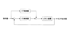
本実施例の可変分光素子の制御部においては、図4に示すように、フィードバック制御とフィードフォワード制御とを組み合わせた制御を行っている。なお、フィードバック制御では指令値とセンサ出力値に基づいて出力値を決定し、フィードフォワード制御では指令値のみに基づいて出力値を決定するように構成されている。フィードバック制御に加えてフィードフォワード制御を組み合わせることにより、フィードバック制御のみの場合と比較して、さらに光学基板の面間隔が収束するまでの時間を短くすることができるためである。 In the control unit of the variable spectral element of the present embodiment, as shown in FIG. 4, control combining feedback control and feedforward control is performed. In the feedback control, the output value is determined based on the command value and the sensor output value, and in the feedforward control, the output value is determined based only on the command value. This is because by combining the feedforward control in addition to the feedback control, it is possible to further shorten the time until the surface interval of the optical substrate converges compared to the case of only the feedback control.
まず、本実施例の可変分光素子の制御部で行われるフィードバック制御について詳細に説明する。 First, feedback control performed by the control unit of the variable spectral element of the present embodiment will be described in detail.
本実施例の可変分光素子において、図3に示すように、固定基板21に対して可動基板22を移動させて一対の光学基板2の面間隔をxoにしようとする場合、まず、図5に示すように、制御部に目標値入力部51を介して、固定基板21の対向する面の重心G1と可動基板22の対向する面の重心G2との間隔の目標値xo、それらの重心同士を結んだ線に垂直な面と可動基板22の対抗する面とがなす第1の角度の目標値θo及び第2の角度の目標値φoを入力する。
In the variable spectroscopic element of this embodiment, as shown in FIG. 3, when the
次に、センサ出力変換部52が、第1〜第4静電容量センサ31、32、33、34により測定された各静電容量センサの配置位置における光学基板の面間隔x1、x2、x3、x4を取得するとともに、それらの面間隔x1、x2、x3、x4を、重心G1と重心G2との間隔の現在値x、第1の角度の現在値θ及び第2の角度の現在値φに変換する。 Next, the sensor output conversion unit 5 2 uses the first to fourth capacitance sensors 3 1 , 3 2 , 3 3 , and 3 4 to determine the surface distance x of the optical substrate at the position where each capacitance sensor is disposed. 1, x 2, x 3, obtains the x 4, their surface distance x 1, x 2, x 3, and x 4, the current value of the distance between the center of gravity G 1 and the center of gravity G 2 x, the first It converts into the current value θ of the angle and the current value φ of the second angle.
具体的には、一対の光学基板2の対向する面の各々の重心同士の間隔xは、以下の式により求められる。
x=(x1+x2+x3+x4)/4
Specifically, the distance x between the centers of gravity of the opposing surfaces of the pair of
x = (x 1 + x 2 + x 3 + x 4 ) / 4
また、一対の光学基板2の対向する面の重心を結んだ線に垂直な面と可動基板22の固定基板21と対抗する面とがなす第1の角度θ及び第2の角度φについては、既知の値である可動基板22の対向する面の重心G2から第1〜第4静電容量センサ31、32、33、34の電極312、322、332、342の中心までの可動基板22の対向する面上における距離r31、r32、r33、r34を用いて、以下の式が成り立つ。
sinθ=(x3−x1)/(r31+r33)
sinφ=(x4−x2)/(r32+r34)
Further, the first angle θ and the second angle φ formed by the surface perpendicular to the line connecting the centers of gravity of the opposing surfaces of the pair of
sin θ = (x 3 −x 1 ) / (r 31 + r 33 )
sin φ = (x 4 −x 2 ) / (r 32 + r 34 )
なお、本実施例においては、
r31=r32=r33=r34=r
であり、第1の角度θ及び第2の角度φはいずれも十分に小さいため、第1の角度θ及び第2の角度φは以下の式により求められる。
θ=(x3−x1)/2r
φ=(x4−x2)/2r
In this embodiment,
r 31 = r 32 = r 33 = r 34 = r
Since both the first angle θ and the second angle φ are sufficiently small, the first angle θ and the second angle φ can be obtained by the following equations.
θ = (x 3 −x 1 ) / 2r
φ = (x 4 −x 2 ) / 2r
次に、差分値算出部53において、目標値入力部51を介して入力された目標値xo、θo、φoと、センサ出力変換部52で変換されたx、θ、φとの、それぞれの差分値ex、eθ、eφを算出する。 Then, the difference value calculating unit 3, input through the target value input unit 5 first target value x o, θ o, φ o and, converted x sensor output conversion unit 5 2, theta, phi The difference values ex, eθ, and eφ are calculated.
次に、指令値算出部54において、差分値算出部53で算出された差分値ex、eθ、eφに基づいてPID制御を行い、指令値xc、θc、φcを求める。 Then, the command value calculating unit 4 performs PID control based calculated by the difference value calculating unit 5 3 difference ex, E.theta, the E?, The command value x c, theta c, determine the phi c.
次に、指令値変換部55において、指令値算出部54で求めた指令値xc、θc、φcを第1〜第4ピエゾ素子41、42、43、44のそれぞれに対する指令値xc1、xc2、xc3、xc4に変換する。指令値xc1、xc2、xc3、xc4はそれぞれ対応する第1〜第4ピエゾ素子41、42、43、44を駆動する図示しないピエゾ素子ドライバに入力され、このピエゾ素子ドライバにより第1〜第4ピエゾ素子41、42、43、44のそれぞれに駆動電圧が印加される。 Next, in the command value converter 5 5 , the command values x c , θ c , and φ c obtained by the command value calculator 5 4 are changed to the first to fourth piezo elements 4 1 , 4 2 , 4 3 , 4 4 . The command values x c1 , x c2 , x c3 , and x c4 are converted for the respective values. The command values x c1 , x c2 , x c3 , x c4 are respectively input to piezo element drivers (not shown) that drive the corresponding first to fourth piezo elements 4 1 , 4 2 , 4 3 , 4 4. A drive voltage is applied to each of the first to fourth piezoelectric elements 4 1 , 4 2 , 4 3 , 4 4 by the driver.
なお、第1〜第4ピエゾ素子41、42、43、44のそれぞれに対する指令値xc1、xc2、xc3、xc4については、可動基板2 2 の対向する面の重心G 2 から既知の値である第1〜第4ピエゾ素子41、42、43、44の中心までの可動基板22の対向する面上における距離r41、r42、r43、r44を用いて、以下の式が成り立つ。
x c1=xc−r41sinθc
x c2=xc−r42sinφc
x c3=xc+r43sinθc
x c4=xc+r44sinφc
For the command values x c1 , x c2 , x c3 , x c4 for each of the first to fourth piezo elements 4 1 , 4 2 , 4 3 , 4 4 , the center of gravity G of the opposing surface of the
x c 1 = x c −r 41 sin θ c
x c 2 = x c −r 42 sinφ c
x c 3 = x c + r 43 sin θ c
x c 4 = x c + r 44 sin φ c
また、本実施例においては、
r41=r42=r43=r44=r
であり、第1の角度についての指令値θc及び第2の角度についての指令値φcはいずれも十分に小さいため、第1〜第4ピエゾ素子41、42、43、44のそれぞれに対する指令値xc1、xc2、xc3、xc4は以下の式により求められる。
xc1=x c −rθc
xc2=x c −rφc
xc3=x c +rθc
xc4=x c +rφc
In this embodiment,
r 41 = r 42 = r 43 = r 44 = r
Since the command value θ c for the first angle and the command value φ c for the second angle are both sufficiently small, the first to fourth piezo elements 4 1 , 4 2 , 4 3 , 4 4 The command values x c1 , x c2 , x c3 , x c4 for each of the above are obtained by the following equations.
x c1 = x c −rθ c
x c2 = x c −rφ c
x c3 = x c + rθ c
x c4 = x c + rφ c
その後、第1〜第4ピエゾ素子41、42、43、44は、それぞれに対する指令値xc1、xc2、xc3、xc4に基づいてピエゾ素子ドライバにより印加される電圧により駆動され、可動基板22を移動させて、一対の光学基板2の面間隔xを変化させる。
Thereafter, the first to fourth piezo elements 4 1 , 4 2 , 4 3 , 4 4 are driven by the voltages applied by the piezo element driver based on the command values x c1 , x c2 , x c3 , x c4 for the respective elements. It is, by moving the
図6は、可変分光素子においてフィードバック制御を行った際のエタロン装置の応答特性に関する実験結果を示すグラフである。なお、縦軸は一対の光学基板の面間隔(nm)、横軸は時間(sec)であり、(a)は従来の可変分光素子による実験結果、(b)は本実施例の可変分光素子による実験結果である。なお、この実験においては、破線で示すように、0.02秒ごとに目標値を切り替えて信号を入力している。 FIG. 6 is a graph showing experimental results regarding response characteristics of the etalon device when feedback control is performed in the variable spectroscopic element. Here, the vertical axis represents the surface spacing (nm) between the pair of optical substrates, the horizontal axis represents time (sec), (a) is the experimental result of a conventional variable spectral element, and (b) is the variable spectral element of this example. It is an experimental result by. In this experiment, as indicated by a broken line, a signal is input by switching the target value every 0.02 seconds.
この図6からもわかるように、本実施例の可変分光素子は、従来の可変分光素子に比べ、一対の光学基板の面間隔が収束するまでの時間が非常に短い。そのため、本発明の可変分光素子は、連続的且つ高速に光学特性を変化させる場合であっても、正確に光学特性を変化させることができる。 As can be seen from FIG. 6, the variable spectroscopic element of this example has a very short time until the distance between the surfaces of the pair of optical substrates converges as compared with the conventional variable spectroscopic element. Therefore, the variable spectroscopic element of the present invention can accurately change the optical characteristics even when the optical characteristics are continuously and rapidly changed.
次に、本実施例の可変分光素子の制御部で行われるフィードフォワード制御について詳細に説明する。 Next, the feedforward control performed by the control unit of the variable spectral element of the present embodiment will be described in detail.
本実施例の可変分光素子のエタロン装置において、第1〜第4ピエゾ素子41、42、43、44により支持される可動基板22は、一対の光学基板の重心同士を結んだ線に沿う方向に対する並進運動と、第1の角度θに関する回転運動と、第2の角度φに関する回転運動の3自由度の三次元的な運動をする。
In the variable spectral element etalon device of this embodiment, the
そして、それらの各運動に対して、エタロン装置は、その質量や材質から求められる固有の特性を有している。そこで、まず、各運動に対するエタロン装置の特性について説明する。 For each of these movements, the etalon device has unique characteristics required from its mass and material. First, the characteristics of the etalon device for each movement will be described.
エタロン装置の並進運動についての特性である伝達関数Gxを求める場合、まず、制御的な考察をしやすくするために、可変分光素子の移動部分の質量をmとし、第1〜第4ピエゾ素子41、42、43、44を、それぞれバネ定数k1、k2、k3、k4を持つバネと減衰定数c x1、c x2、c x3、c x4を持つダンパを結合したものとしてエタロン装置をモデル化する。 When obtaining the transfer function G x which is a characteristic of the translational motion of the etalon device, first, in order to facilitate control consideration, the mass of the moving part of the variable spectroscopic element is set to m, and the first to fourth piezo elements 4 1 , 4 2 , 4 3 , 4 4 have spring constants k 1 , k 2 , k 3 , k 4 and damping constants c x 1 , c x 2 , c x 3 , c x 4 , respectively. The etalon device is modeled as a combination of dampers.
なお、質量mは、エタロン装置の外枠1に対して移動する第1〜第4ピエゾ素子41、42、43、44の質量及び可動基板22の質量によって決まる値であり、バネ定数k1、k2、k3、k4は、第1〜第4ピエゾ素子41、42、43、44及び可動基板22の構造及び材質に基づいた材料解析のシミュレーションにより求めることのできる定数であり、減衰定数cx1、cx2、cx3、cx4は、質量m及びバネ定数k1、k2、k3、k4と信号を入力した際の可動基板22及び第1〜第4ピエゾ素子41、42、43、44の振動の状態とから求めることのできる定数である。
The mass m is a value determined by the mass of the first to fourth piezo elements 4 1 , 4 2 , 4 3 , 4 4 and the mass of the
このモデルに基づいて、並進運動についての運動方程式を立てると、
mx”=Fx=f1+f2+f3+f4
となる。なお、x”は質量mの重心が固定端からxの距離にあるときの並進運動についての加速度、Fxは質量mの重心が固定端からxの距離にあるときの並進運動について質量mに対して加わる力の大きさ、f1、f2、f3、f4はそれぞれ第1〜第4ピエゾ素子41、42、43、44の各々により発生する力の大きさである。
Based on this model, when the equation of motion for translational motion is established,
mx ″ = F x = f 1 + f 2 + f 3 + f 4
It becomes. X ″ is the acceleration for translational motion when the center of mass of the mass m is at a distance x from the fixed end, and F x is mass m for translational motion when the center of gravity of the mass m is at the distance x from the fixed end. magnitude of the force, at f 1, f 2, f 3, f 4 4 first through fourth piezoelectric elements respectively 1, 4 2, 4 3, 4 of the force generated by each of the four sizes is applied for .
ここで、一対の光学基板2の面間隔の目標値をuとすると、質量mに対して第1〜第4ピエゾ素子41、42、43、44の各々により加えられる力f1、f2、f3、f4は、
f1=k1(u1−x1)−cx1x1’
f2=k2(u2−x2)−cx2x2’
f3=k3(u3−x3)−cx3x3’
f4=k4(u4−x4)−cx4x4’
となる。なお、u1、u2、u3、u4は一対の光学基板2の面間隔が目標値uとなったときの固定端から第1〜第4ピエゾ素子41、42、43、44までの並進運動に沿う方向の距離、x1、x2、x3、x4は固定端から可動基板22の第1〜第4ピエゾ素子41、42、43、44の配置位置までの並進運動に沿う方向についての距離、x1’、x2’、x3’、x4’は可動基板22の第1〜第4ピエゾ素子41、42、43、44の配置位置における並進運動についての速度である。
Here, when the target value of the surface spacing of the pair of
f 1 = k 1 (u 1 −x 1 ) −c x1 x 1 ′
f 2 = k 2 (u 2 -x 2) -c x2 x 2 '
f 3 = k 3 (u 3 -x 3) -c x3 x 3 '
f 4 = k 4 (u 4 -x 4) -c x4 x 4 '
It becomes. U 1 , u 2 , u 3 , u 4 are the first to fourth piezo elements 4 1 , 4 2 , 4 3 , from the fixed end when the surface spacing of the pair of
このとき、本実施例の可変分光素子のエタロン装置においては、
k1=k2=k3=k4=k
cx1=cx2=cx3=cx4=cx
であるため、
f1=k(u1−x1)−cxx1’
f2=k(u2−x2)−cxx2’
f3=k(u3−x3)−cxx3’
f4=k(u4−x4)−cxx4’
となる。
At this time, in the etalon device of the variable spectral element of the present embodiment,
k 1 = k 2 = k 3 = k 4 = k
c x1 = c x2 = c x3 = c x4 = c x
Because
f 1 = k (u 1 −x 1 ) −c x x 1 ′
f 2 = k (u 2 −x 2 ) −c x x 2 ′
f 3 = k (u 3 −x 3 ) −c x x 3 ′
f 4 = k (u 4 −x 4 ) −c x x 4 ′
It becomes.
また、xは固定端から可動基板22の重心G2までの距離と等しいため、
x=(x1+x2+x3+x4)/4
となり、x’は固定端から可動基板22の重心G2が距離xにあるときの速度と等しいため、
x’=(x1’+x2’+x3’+x4’)/4
となる。
Further, since x is equal to the distance from the fixed end to the center of gravity G 2 of the
x = (x 1 + x 2 + x 3 + x 4 ) / 4
Next, x 'for the same from the fixed end and the speed at which the center of gravity G 2 of the
x ′ = (x 1 ′ + x 2 ′ + x 3 ′ + x 4 ′) / 4
It becomes.
そして、これらをまとめると、
mx”=Fx=ku1+ku2+ku3+ku4−4kx−4cxx’
となる。
And when these are put together,
mx ″ = F x = ku 1 + ku 2 + ku 3 + ku 4 -4kx-4c x x ′
It becomes.
ここで、
u=(u1+u2+u3+u4)/4
としてラプラス変換すると、
s2X=4k/m・U1〜4−4k/m・X−4c x /m・sX
となり、並進運動についての伝達関数Gxは、
Gx=X/U1〜4
=(4k/m)/(s2+4cx/m・s+4k/m)
=Ax/(s2+Bxs+Cx)
となる。
なお、A x =4k/m(kはアクチュエータのバネ定数、mはエタロン装置の移動部分の質量)は、エタロン装置の出入力特性の感度を表すパラメータである。B x =4c x /m(c x はバネ常数がk、質量がmのときに信号を入力したときの可動基板の振動の減衰から求められる定数)は、減衰特性を示すパラメータであり、このパラメータ値が大きいと減衰特性が良くなり振動が抑制される。C x =4k/mは、振動の周波数に関連したパラメータであり、このパラメータ値が大きいと振動周期が短くなり立ち上がりが高速になる。
here,
u = (u 1 + u 2 + u 3 + u 4 ) / 4
As Laplace transform,
s 2 X = 4 k / m · U 1 to 4 -4 k / m · X-4c x / m · sX
The transfer function G x for translational motion is
G x = X / U 1-4
= (4k / m) / (s 2 + 4c x / m · s + 4k / m)
= A x / (s 2 + B x s + C x )
It becomes.
A x = 4 k / m (k is the spring constant of the actuator, m is the mass of the moving part of the etalon device) is a parameter representing the sensitivity of the input / output characteristics of the etalon device. B x = 4c x / m (c x is a constant obtained from damping of vibration of the movable substrate when a signal is input when the spring constant is k and the mass is m) is a parameter indicating damping characteristics. When the parameter value is large, the damping characteristic is improved and vibration is suppressed. C x = 4 k / m is a parameter related to the frequency of vibration. When this parameter value is large, the vibration period is shortened and the rise is fast.
同様にして、エタロン装置の第1の角度θに関する回転運度についての特性である伝達関数Gθ、第2の角度φに関する回転運度についての特性である伝達関数Gφは、
Gθ=Θ/U1、3
=(rk/J)/(s2+2cθ/J・s+2r2k/J)
=Aθ/(s2+Bθs+Cθ)
Gφ=Φ/U2、4
=(rk/J)/(s2+2cφ/J・s+2r2k/J)
=Aφ/(s2+Bφs+Cφ)
となる。なお、Jは慣性モーメントであり、エタロン装置の外枠1に対して移動する第1〜第4ピエゾ素子41、42、43、44の質量及び可動基板22の質量によって決まる値である。また、減衰定数cθ、cφは、慣性モーメントJ及びバネ定数k1、k2、k3、k4と信号を入力した際の可動基板22の振動の状態とから求めることのできる定数である。また、Aθ、Aφはエタロン装置の出入力特性の感度を表すパラメータ、Bθ、Bφは減衰特性を示すパラメータ、Cθ、Cφは振動の周波数に関連したパラメータである。
Similarly, the transfer function Gθ, which is a characteristic regarding the rotational angle with respect to the first angle θ of the etalon device, and the transfer function Gφ, which is a characteristic regarding the rotational angle regarding the second angle φ, are:
Gθ = Θ / U 1 , 3
= (Rk / J) / (s 2 + 2cθ / J · s + 2r 2 k / J)
= Aθ / ( s 2 + Bθs + Cθ )
Gφ = Φ / U2, 4
= (Rk / J) / (s 2 + 2cφ / J · s + 2r 2 k / J)
= Aφ / ( s 2 + Bφs + Cφ )
It becomes. Note that J is a moment of inertia and is determined by the mass of the first to fourth piezo elements 4 1 , 4 2 , 4 3 , 4 4 and the mass of the
したがって、フィードフォワード制御を行わない場合、入力値pに対する出力値y、つまりエタロン装置の挙動は、エタロン装置の持つ特性から導かれる伝達関数Gx、Gθ、Gφ(以下、総称して「伝達関数G」という。)が掛けられた
y=G・p
となり、指令値と実際の動作とが一致しない。
Therefore, when feedforward control is not performed, the output value y with respect to the input value p , that is, the behavior of the etalon device, is derived from transfer functions G x , Gθ, Gφ (hereinafter collectively referred to as “transfer function”) derived from the characteristics of the etalon device. G ”)) multiplied by y = G · p
Thus, the command value does not match the actual operation.
そこで、本実施例の可変分光素子においては、入力値とエタロンの挙動が一致するように以下のようにフィードフォワード制御を行う。
y=1/G・G・p
Therefore, in the variable spectroscopic element of the present embodiment, feedforward control is performed as follows so that the input value and the etalon behavior match.
y = 1 / G ・ G ・p
ここで、pに掛ける1/Gは
1/G=(s2+Bs+C)/A
である。
Here, 1 / G multiplied by p is 1 / G = (s 2 + B s + C ) / A
It is.
したがって、入力値pとしたときにフィードフォワード制御が行われた出力値yは次のようになる。
y(t)=(d2 p/dt2+B・dp/dt+C・p)/A
Therefore, when the input value p is used, the output value y for which the feedforward control is performed is as follows.
y (t) = (d 2 p / dt 2 + B · d p / dt + C · p ) / A
また、本実施例の可変分光素子においては、フィードバック制御とフィードフォワード制御は、一対の光学基板の重心同士を結んだ線に沿う方向に対する並進運動と、第1の角度θに関する回転運動と、第2の角度φに関する回転運動のそれぞれについて別々に行われ、図4に示すようにFB制御器とFF制御器からの出力値を足し合わせてx、θ、φの値として、図5に示す指令値変換部55に入力される。指令値変換部55は指令値xc、θc、φcを第1〜第4ピエゾ素子41、42、43、44のそれぞれに対する指令値xc1、xc2、xc3、xc4に変換する。 In the variable spectroscopic element of the present embodiment, the feedback control and the feedforward control include translational motion in a direction along a line connecting the centers of gravity of the pair of optical substrates, rotational motion related to the first angle θ, 5 is performed separately for each of the rotational movements related to the angle φ of 2, and the command values shown in FIG. 5 are obtained by adding the output values from the FB controller and the FF controller as shown in FIG. It is input to a value converter 5 5. The command value conversion unit 5 5 converts the command values x c , θ c , and φ c into command values x c1 , x c2 , x c3 , for the first to fourth piezo elements 4 1 , 4 2 , 4 3 , 4 4 , respectively. Convert to xc4 .
図7は、可変分光素子のエタロン装置の応答特性に関する実験結果を示すグラフである。なお、縦軸は一対の光学基板の面間隔(nm)、横軸は時間(sec)であり、(a)はフィードバック制御のみにより制御を行った場合の実験結果、(b)はフィードバック制御とフィードフォワード制御を組み合わせて制御を行った場合の実験結果である。なお、破線は入力信号を表している。 FIG. 7 is a graph showing experimental results regarding response characteristics of the etalon device of the variable spectroscopic element. The vertical axis is the distance between the surfaces of the pair of optical substrates (nm), the horizontal axis is the time (sec), (a) is the experimental result when the control is performed only by feedback control, and (b) is the feedback control. It is an experimental result at the time of performing control combining feedforward control. The broken line represents the input signal.
この図7からもわかるように、フィードバック制御とフィードフォワード制御を組み合わせて制御を行った場合、フィードバック制御のみにより制御を行った場合に比べ、オーバーシュートが非常に小さく抑えられる。また、一対の光学基板の面間隔が収束する時間、具体的には、面間隔の距離が目標値の±3nm程度で安定するまでの時間が非常に短い。さらに、入力信号に対する反応速度も速い。そのため、本発明の可変分光素子は、連続的且つ高速に光学特性を変化させる場合であっても、正確に光学特性を変化させることができる。 As can be seen from FIG. 7, when the control is performed by combining the feedback control and the feedforward control, the overshoot can be suppressed to be very small as compared with the case where the control is performed only by the feedback control. In addition, the time required for the distance between the surfaces of the pair of optical substrates to converge, specifically, the time required for the distance between the surfaces to stabilize at the target value of about ± 3 nm is very short. Furthermore, the response speed to the input signal is fast. Therefore, the variable spectroscopic element of the present invention can accurately change the optical characteristics even when the optical characteristics are continuously and rapidly changed.
なお、本実施例においては、フィードバック制御とフィードフォワード制御を、一対の光学基板2の重心同士の間隔x、第1の角度θ及び第2の角度φのいずれの制御においても行っているが、必ずしもそれら全てについて行う必要はなく、いずれか一つのみについて行っても良い。
In the present embodiment, feedback control and feedforward control are performed in any control of the distance x between the centers of gravity of the pair of
次に、図8〜図11を用いて本実施例の可変分光素子のエタロン装置の変形例を示す。 Next, a modification of the etalon device of the variable spectral element of the present embodiment will be described with reference to FIGS.
図8に示すエタロン装置は、上記実施例の可変分光素子のエタロン装置と異なり、第1静電容量センサ31及び第1ピエゾ素子41と、第2静電容量センサ32及び第2ピエゾ素子42と、第3静電容量センサ33及び第3ピエゾ素子43と、第4静電容量センサ34及び第4ピエゾ素子44とは、一対の光学基板2の対向する面の各々の重心を結んだ線に沿う方向からみて、等間隔に配置されていない。
The etalon device shown in FIG. 8 differs from the etalon device of the variable spectroscopic element of the above embodiment in that the first capacitance sensor 3 1 and the first piezo element 4 1 , the second capacitance sensor 3 2 and the second piezo device. and element 4 2, and the third capacitive sensor 3 3 and the third piezoelectric element 4 3, and the fourth capacitive sensor 3 4 and the fourth piezoelectric element 4 4, the pair of
しかし、このような配置であっても、第1静電容量センサ31及び第1ピエゾ素子41と第3静電容量センサ33及び第3ピエゾ素子43、第2静電容量センサ32及び第2ピエゾ素子42と第4静電容量センサ34及び第4ピエゾ素子44が、一対の光学基板2の対向する面の各々の重心を結んだ線に沿う方向からみて、その重心を結んだ線を軸として対称となる位置に配置されていれば、制御部において上記実施例の可変分光素子のエタロン装置と同様の演算を行って制御を行うことができる。
However, even with such an arrangement, the first capacitance sensor 3 1, the first piezo element 4 1 , the third capacitance sensor 3 3, the third piezo element 4 3 , and the second capacitance sensor 3. 2 and the second piezo element 4 2 , the fourth capacitance sensor 3 4 and the fourth piezo element 4 4 , as viewed from the direction along the line connecting the centers of gravity of the opposing surfaces of the pair of
図9及び図10に示すエタロン装置は、上記実施例の可変分光素子のエタロン装置と異なり、第1静電容量センサ31と第1ピエゾ素子41、第2静電容量センサ32と第2ピエゾ素子42、第3静電容量センサ33と第3ピエゾ素子43、第4静電容量センサ34と第4ピエゾ素子44が、一対の光学基板2の対向する面の各々の重心を結んだ線に沿う方向からみて、重ならない位置に配置されている。
The etalon device shown in FIG. 9 and FIG. 10 is different from the etalon device of the variable spectroscopic element of the above embodiment, and the first capacitance sensor 3 1 , the first piezo element 4 1 , the second capacitance sensor 3 2, and the second one . 2 piezo elements 4 2 , third capacitance sensor 3 3 and third piezo element 4 3 , fourth capacitance sensor 3 4 and fourth piezo element 4 4 are respectively disposed on the opposing surfaces of the pair of
しかし、このような配置であっても、一対の光学基板2の対向する面の各々の重心を結んだ線に沿う方向からみて、第1〜第4ピエゾ素子41、42、43、44の各々が、第1〜第4静電容量センサ31、32、33、34の各々の中心方向へ伸びる線の線上に配置されていれば、制御部において上記実施例の可変分光素子のエタロン装置と同様の演算を行って制御を行うことができる。
However, even in such an arrangement, the first to fourth piezo elements 4 1 , 4 2 , 4 3 , as viewed from the direction along the line connecting the centers of gravity of the opposing surfaces of the pair of
図11に示すエタロン装置は、上記実施例の可変分光素子のエタロン装置と異なり、外枠1を備えておらず、第1ピエゾ素子41、第2ピエゾ素子42、第3ピエゾ素子43、第4ピエゾ素子44が、それぞれ、エタロン装置を通過する光を遮らないようにして、固定基板21の対向する面上に固定されている。
The etalon device shown in FIG. 11 is not provided with the
しかし、このような構成であっても、制御部において上記実施例の可変分光素子のエタロン装置と同様の演算を行って制御を行うことができる。 However, even with such a configuration, the control unit can perform control by performing the same calculation as the etalon device of the variable spectral element of the above-described embodiment.
図12及び図13を用いて、本発明に係る可変分光素子であるエタロン装置を備えた可変分光素子の第2の実施例について説明する。なお、本実施例の可変分光素子のエタロン装置を構成する部材は、実施例1のエタロン装置を構成する部材と同じであるため、同じ構成を有する部材には、同一の符号を付すとともに、それらについての詳細な説明は省略する。また、本実施例の可変分光素子の制御部の構成や内部で行われる演算は、実施例1の可変分光素子の制御部で行われる演算とほぼ同じであるため、それらについての詳細な説明は省略する。 A second embodiment of the variable spectroscopic element including the etalon device that is the variable spectroscopic element according to the present invention will be described with reference to FIGS. 12 and 13. In addition, since the member which comprises the etalon apparatus of the variable spectroscopy element of a present Example is the same as the member which comprises the etalon apparatus of Example 1, while attaching the same code | symbol to the member which has the same structure, those The detailed description about is omitted. In addition, since the configuration of the control unit of the variable spectroscopic element of the present embodiment and the calculation performed internally are almost the same as the calculation performed by the control unit of the variable spectroscopic element of Example 1, a detailed description thereof is as follows. Omitted.
なお、図12は、本実施例に係る可変分光素子のエタロン装置を示す断面図である。図13は、図12のエタロン装置の平面図である。 In addition, FIG. 12 is sectional drawing which shows the etalon apparatus of the variable spectroscopy element based on a present Example. 13 is a plan view of the etalon device of FIG.
図12及び図13を用いて、この可変分光素子のエタロン装置の構成について説明する。 The configuration of the variable spectroscopic etalon device will be described with reference to FIGS.
本実施例の可変分光素子のエタロン装置においては、実施例1の可変分光素子のエタロン装置と異なり、第1〜第4ピエゾ素子41、42、43、44と第1〜第4静電容量センサ31、32、33、34が、一対の光学基板2の対向する面の各々の重心を結んだ線に沿う方向からみて、交互に等間隔となるように環状に配置されている。
In the variable spectral element etalon device of the present embodiment, unlike the variable spectral element etalon device of the first embodiment, the first to fourth piezo elements 4 1 , 4 2 , 4 3 , 4 4 and the first to fourth piezo elements. Capacitance sensors 3 1 , 3 2 , 3 3 , and 3 4 are annularly formed so as to be alternately spaced at an equal interval when viewed from the direction along the line connecting the centers of gravity of the opposing surfaces of the pair of
次に、本実施例に係る可変分光素子のエタロン装置における可動基板22の動作及びその制御について説明する。
Next, the operation of the
実施例1の可変分光素子においては、第1〜第4静電容量センサ31、32、33、34の出力値から一対の光学基板2の対向する面の重心同士の間隔xを算出し、第1、第3静電容量センサ31、33の出力値から第1の角度θを算出し、第2、第4静電容量センサ32、34の出力値から第2の角度φを算出する。そして、第1、第3ピエゾ素子41、43の駆動を重心同士の間隔xと第1の角度θに基づいて制御し、第2、第4ピエゾ素子42、44の駆動を重心同士の間隔xと第2の角度φに基づいて制御している。
In the variable spectroscopic element of Example 1, the distance x between the centers of gravity of the opposing surfaces of the pair of
これに対し、本実施例の可変分光素子においては、第1〜第4静電容量センサ31、32、33、34の全ての出力値を用いて重心同士の間隔x、第1の角度θ及び第2の角度φを算出する。そして、第1〜第4ピエゾ素子41、42、43、44それぞれの駆動を重心同士の間隔x、第1の角度θ及び第2の角度φに基づいて制御する。 On the other hand, in the variable spectroscopic element of the present embodiment, the interval x between the centroids and the first are obtained by using all the output values of the first to fourth capacitance sensors 3 1 , 3 2 , 3 3 , 3 4 . The angle θ and the second angle φ are calculated. Then, the driving of each of the first to fourth piezo elements 4 1 , 4 2 , 4 3 , 4 4 is controlled based on the distance x between the centers of gravity, the first angle θ, and the second angle φ.
このように、本実施例では、静電容量センサ3と対応するピエゾ素子4とが、一対の光学基板2の対向する面の各々の重心を結んだ線に沿う方向からみて、重なる位置に配置されていないが、静電容量センサ3が検出した一対の光学基板2の対向する面同士の面間隔を、第1〜第4ピエゾ素子41、42、43、44の位置における光学基板の面間隔x1、x2、x3、x4に変換しているため、実施例1と同一の制御を行うことができる。
Thus, in this embodiment, the capacitance sensor 3 and the corresponding piezo element 4 are arranged at positions overlapping each other when viewed from the direction along the line connecting the centers of gravity of the opposing surfaces of the pair of
したがって、本実施例2においても、実施例1の可変分光素子と同様に、本実施例の可変分光素子は、従来の可変分光素子に比べ、一対の光学基板2の面間隔が収束するまでの時間が非常に短い。そのため、本発明の可変分光素子は、連続的且つ高速に光学特性を変化させる場合であっても、正確に光学特性を変化させることができる。
Therefore, also in the second embodiment, like the variable spectroscopic element of the first embodiment, the variable spectroscopic element of the present embodiment is different from the conventional variable spectroscopic element until the distance between the surfaces of the pair of
1 外枠
11 筒状部材
12,13 環状部材
12a,13a 開口部
2 一対の光学基板
21 固定基板
22 可動基板
31 第1静電容量センサ
32 第2静電容量センサ
33 第3静電容量センサ
34 第4静電容量センサ
311,312,321,322,331,332,341,342 電極
41 第1ピエゾ素子
42 第2ピエゾ素子
43 第3ピエゾ素子
44 第4ピエゾ素子
51 目標値入力部
52 センサ出力変換部
53 差分値算出部
54 指令値算出部
55 指令値変換部
G1 固定基板の対向する面における重心
G2 可動基板の対向する面における重心
1
Claims (4)
前記第1静電容量センサと第3静電容量センサとが、前記一対の光学基板の対向する面の各々の重心を結んだ線を軸として対称となる位置に配置されており、
前記第2静電容量センサと第4静電容量センサとが、前記一対の光学基板の対向する面の各々の重心を結んだ線を軸として対称となる位置に配置されており、
前記第1乃至第4アクチュエータの各々が、前記一対の光学基板の対向する面の各々の重心から前記第1乃至第4静電容量センサの各々の中心方向へ伸びる線上に配置されており、
前記第1乃至第4静電容量センサによる信号から前記一対の光学基板の対向する面の各々の重心同士の間隔を算出し、前記第1静電容量センサによる信号と前記第3静電容量センサによる信号とから前記重心を結んだ線に垂直な面と移動させる前記光学基板の前記対向する面とがなす第1の角度を算出し、前記第2静電容量センサによる信号と前記第4静電容量センサによる信号とから前記重心を結んだ線に垂直な面と移動させる前記光学基板の前記対向する面とがなす第2の角度を算出し、前記重心同士の間隔及び前記第1の角度に基づいて前記第1及び第3アクチュエータを駆動し、前記重心同士の間隔及び前記第2の角度に基づいて前記第2及び第4アクチュエータを駆動し、前記重心同士の間隔、前記第1の角度及び前記第2の角度についてフィードバック制御を行うとともに、前記重心同士の間隔、前記第1の角度又は前記第2の角度の少なくとも一つについてフィードフォワード制御を行う制御部を備えていることを特徴とする可変分光素子。 The pair of optical substrates disposed so as to face each other with a space therebetween, and the pair of electrode portions disposed on each of the opposing surfaces of the pair of optical substrates, respectively, and the pair at each disposed position The first to fourth capacitance sensors for detecting the surface interval between the opposing surfaces of the optical substrate, and at least one of the pair of optical substrates is moved relative to the other of the pair of optical substrates. In the variable spectroscopic element including the first to fourth actuators that change the surface interval between the opposing surfaces,
The first capacitance sensor and the third capacitance sensor are arranged at positions symmetrical with respect to a line connecting the centers of gravity of the opposing surfaces of the pair of optical substrates,
The second capacitance sensor and the fourth capacitance sensor are arranged at positions symmetrical with respect to a line connecting the centers of gravity of the opposing surfaces of the pair of optical substrates,
Each of the first to fourth actuators is disposed on a line extending from the center of gravity of each of the opposing surfaces of the pair of optical substrates toward the center of each of the first to fourth capacitance sensors,
The distance between the centers of gravity of the opposing surfaces of the pair of optical substrates is calculated from the signals from the first to fourth capacitance sensors, and the signal from the first capacitance sensor and the third capacitance sensor are calculated. The first angle formed by the signal perpendicular to the line connecting the center of gravity and the opposing surface of the optical substrate to be moved is calculated from the signal obtained by A second angle formed by a surface perpendicular to a line connecting the centroids from the signal from the capacitance sensor and the opposing surface of the optical substrate to be moved is calculated, and an interval between the centroids and the first angle are calculated. wherein the first and third actuator drives, the centroid distance between and on the basis of the second angular drives the second and fourth actuators, spacing of the center of gravity between the first angle based on And the second angle Performs feedback control with the centroid distance between the first angle or the variable spectroscopic element characterized in that it comprises a control unit that performs feedforward control for at least one of said second angle.
前記フィードフォワード制御が、入力値を2階微分した値と、入力値の微分値に前記アクチュエータの減衰定数を乗算し前記可変分光素子の移動部分の質量で除算した値と、入力値に前記アクチュエータのバネ定数を乗算し前記可変分光素子の移動部分の質量で除算した値との和を、前記アクチュエータのバネ定数を前記可変分光素子の移動部分の質量で除算した値で除算した値を出力値として出力する制御であることを特徴とする請求項1に記載の可変分光素子。 The feedback control is PID control;
The feedforward control includes a value obtained by second-order differentiation of the input value, a value obtained by multiplying the derivative value of the input value by the attenuation constant of the actuator and dividing by the mass of the moving part of the variable spectroscopic element, and the input value by the actuator. The value obtained by dividing the sum of the spring constant of the actuator by the mass of the moving part of the variable spectroscopic element and the sum of the value obtained by multiplying the spring constant of the variable spectroscopic element by the mass of the moving part of the variable spectroscopic element. The variable spectroscopic element according to claim 1, wherein the variable spectroscopic element is a control to output as follows.
前記フィードフォワード制御が、入力値pに対し、
y(t)=(d2 p/dt2+B・dp/dt+C・p)/A
という出力値を出力する制御であることを特徴とする請求項1または請求項2に記載の可変分光素子。
ただし、A=4k/m(kは前記アクチュエータのバネ定数、mは前記可変分光素子の移動部分の質量)、B=4c/m(cは前記アクチュエータのバネ定数がk、前記可変分光素子の移動部分の質量をmとして信号を入力した場合に前記可変分光素子の移動部分の振動の減衰から求められる定数)、C=4k/mである。 The feedback control is PID control;
The feedforward control is performed with respect to the input value p .
y (t) = (d 2 p / dt 2 + B · d p / dt + C · p ) / A
The variable spectroscopic element according to claim 1, wherein the output value is a control for outputting the output value.
However, A = 4 k / m (k is the spring constant of the actuator, m is the mass of the moving part of the variable spectroscopic element), B = 4 c / m (c is the spring constant of the actuator k, When a signal is input with the mass of the moving part as m, a constant obtained from attenuation of vibration of the moving part of the variable spectroscopic element), C = 4 k / m.
前記第1静電容量センサと第3静電容量センサとが、前記一対の光学基板の対向する面の各々の重心を結んだ線を軸として対称となる位置に配置されており、
前記第2静電容量センサと第4静電容量センサとが、前記一対の光学基板の対向する面の各々の重心を結んだ線を軸として対称となる位置に配置されており、
前記第1乃至第4静電容量センサと前記第1乃至第4アクチュエータが、前記一対の光学基板の対向する面の各々の重心を結んだ線を軸として該軸に沿う方向からみて交互に等角度となるように配置されており、
前記第1乃至第4静電容量センサによる信号から前記一対の光学基板の対向する面の各々の重心同士の間隔を算出し、前記第1乃至第4の静電容量センサによる信号から求めた第1及び第3アクチュエータの配置位置における前記一対の光学基板の対向する面同士の面間隔の値を用いて前記重心を結んだ線に垂直な面と移動させる前記光学基板の前記対向する面とがなす第1の角度を算出し、前記第1乃至第4の静電容量センサによる信号から求めた第2及び第4アクチュエータの配置位置における前記一対の光学基板の対向する面同士の面間隔の値を用いて前記重心を結んだ線に垂直な面と移動させる前記光学基板の前記対向する面とがなす第2の角度を算出し、前記重心同士の間隔、前記第1の角度及び前記第2の角度に基づいて前記第1乃至第4アクチュエータを駆動し、前記重心同士の間隔、前記第1の角度及び前記第2の角度についてフィードバック制御を行うとともに、前記重心同士の間隔、前記第1の角度又は前記第2の角度の少なくとも一つについてフィードフォワード制御を行う制御部を備えていることを特徴とする可変分光素子。 The pair of optical substrates disposed so as to face each other with a space therebetween, and the pair of electrode portions disposed on each of the opposing surfaces of the pair of optical substrates, respectively, and the pair at each disposed position The first to fourth capacitance sensors for detecting the surface interval between the opposing surfaces of the optical substrate, and at least one of the pair of optical substrates is moved relative to the other of the pair of optical substrates. In the variable spectroscopic element including the first to fourth actuators that change the surface interval between the opposing surfaces,
The first capacitance sensor and the third capacitance sensor are arranged at positions symmetrical with respect to a line connecting the centers of gravity of the opposing surfaces of the pair of optical substrates,
The second capacitance sensor and the fourth capacitance sensor are arranged at positions symmetrical with respect to a line connecting the centers of gravity of the opposing surfaces of the pair of optical substrates,
The first to fourth capacitance sensors and the first to fourth actuators are alternately viewed from the direction along the axis with a line connecting the centers of gravity of the opposing surfaces of the pair of optical substrates as an axis. It is arranged to be at an angle,
The distance between the centers of gravity of each of the opposing surfaces of the pair of optical substrates is calculated from the signals from the first to fourth capacitance sensors, and the first obtained from the signals from the first to fourth capacitance sensors. The surface perpendicular to the line connecting the centroids using the value of the surface spacing between the opposing surfaces of the pair of optical substrates at the positions where the first and third actuators are disposed and the opposing surfaces of the optical substrate to be moved A first angle formed is calculated, and a value of a surface interval between the opposing surfaces of the pair of optical substrates at the arrangement position of the second and fourth actuators obtained from signals from the first to fourth capacitance sensors. Is used to calculate a second angle formed by a surface perpendicular to the line connecting the centroids and the opposing surface of the optical substrate to be moved, and the interval between the centroids, the first angle, and the second Based on the angle of To drive the fourth actuator to perform feedback control on the distance between the centroids, the first angle, and the second angle, and the distance between the centroids, the first angle, or the second angle. A variable spectroscopic element comprising a control unit that performs feedforward control for at least one.
Priority Applications (5)
| Application Number | Priority Date | Filing Date | Title |
|---|---|---|---|
| JP2010078214A JP5363394B2 (en) | 2010-03-30 | 2010-03-30 | Variable spectroscopic element |
| CN201180017455.9A CN102822720B (en) | 2010-03-30 | 2011-03-15 | Variable spectral element |
| EP11762564A EP2555038A1 (en) | 2010-03-30 | 2011-03-15 | Variable spectral element |
| PCT/JP2011/055996 WO2011122324A1 (en) | 2010-03-30 | 2011-03-15 | Variable spectral element |
| US13/617,939 US8422020B2 (en) | 2010-03-30 | 2012-09-14 | Variable spectral element |
Applications Claiming Priority (1)
| Application Number | Priority Date | Filing Date | Title |
|---|---|---|---|
| JP2010078214A JP5363394B2 (en) | 2010-03-30 | 2010-03-30 | Variable spectroscopic element |
Publications (3)
| Publication Number | Publication Date |
|---|---|
| JP2011209575A JP2011209575A (en) | 2011-10-20 |
| JP2011209575A5 JP2011209575A5 (en) | 2013-05-16 |
| JP5363394B2 true JP5363394B2 (en) | 2013-12-11 |
Family
ID=44712045
Family Applications (1)
| Application Number | Title | Priority Date | Filing Date |
|---|---|---|---|
| JP2010078214A Expired - Fee Related JP5363394B2 (en) | 2010-03-30 | 2010-03-30 | Variable spectroscopic element |
Country Status (5)
| Country | Link |
|---|---|
| US (1) | US8422020B2 (en) |
| EP (1) | EP2555038A1 (en) |
| JP (1) | JP5363394B2 (en) |
| CN (1) | CN102822720B (en) |
| WO (1) | WO2011122324A1 (en) |
Families Citing this family (5)
| Publication number | Priority date | Publication date | Assignee | Title |
|---|---|---|---|---|
| JP5363394B2 (en) | 2010-03-30 | 2013-12-11 | オリンパス株式会社 | Variable spectroscopic element |
| JP5363393B2 (en) * | 2010-03-30 | 2013-12-11 | オリンパス株式会社 | Variable spectroscopic element |
| JP5530375B2 (en) * | 2011-02-01 | 2014-06-25 | オリンパス株式会社 | Variable spectroscopic element |
| JP2015141209A (en) * | 2014-01-27 | 2015-08-03 | セイコーエプソン株式会社 | Actuator control device, optical module, and electronic apparatus |
| US9568301B2 (en) * | 2014-04-11 | 2017-02-14 | General Electric Company | Systems and methods for capacitive proximity sensing |
Family Cites Families (14)
| Publication number | Priority date | Publication date | Assignee | Title |
|---|---|---|---|---|
| JPH06241899A (en) * | 1993-01-29 | 1994-09-02 | Shimadzu Corp | Etalon driving mechanism |
| CN2276676Y (en) * | 1996-05-02 | 1998-03-18 | 华中理工大学 | Variable reflector |
| JP4164450B2 (en) * | 2002-01-29 | 2008-10-15 | 松下電器産業株式会社 | Deformable mirror and light control apparatus including the deformable mirror |
| CN100405122C (en) * | 2002-11-06 | 2008-07-23 | 松下电器产业株式会社 | Microactuator provided with displacement detection function, and deformable mirror provided with this microactuator |
| JP3812550B2 (en) * | 2003-07-07 | 2006-08-23 | セイコーエプソン株式会社 | Tunable optical filter |
| US7859167B2 (en) * | 2004-03-08 | 2010-12-28 | Panasonic Corporation | Micro actuator having tilt and vertical displacement and device having such micro actuator |
| JP4710737B2 (en) | 2006-06-23 | 2011-06-29 | 日産自動車株式会社 | Brake device for vehicle |
| JP5085101B2 (en) | 2006-11-17 | 2012-11-28 | オリンパス株式会社 | Variable spectroscopic element |
| JP2008183350A (en) * | 2007-01-31 | 2008-08-14 | Olympus Corp | Variable spectroscopic element, spectroscopic device and endoscopic system |
| JP2008197362A (en) * | 2007-02-13 | 2008-08-28 | Olympus Corp | Variable spectroscopic element |
| JP5798709B2 (en) * | 2009-03-04 | 2015-10-21 | セイコーエプソン株式会社 | Optical filter and optical module having the same |
| JP2010224011A (en) * | 2009-03-19 | 2010-10-07 | Olympus Corp | Etalon device and optical unit equipped with the same |
| JP5363394B2 (en) | 2010-03-30 | 2013-12-11 | オリンパス株式会社 | Variable spectroscopic element |
| JP5363393B2 (en) * | 2010-03-30 | 2013-12-11 | オリンパス株式会社 | Variable spectroscopic element |
-
2010
- 2010-03-30 JP JP2010078214A patent/JP5363394B2/en not_active Expired - Fee Related
-
2011
- 2011-03-15 EP EP11762564A patent/EP2555038A1/en not_active Withdrawn
- 2011-03-15 WO PCT/JP2011/055996 patent/WO2011122324A1/en active Application Filing
- 2011-03-15 CN CN201180017455.9A patent/CN102822720B/en not_active Expired - Fee Related
-
2012
- 2012-09-14 US US13/617,939 patent/US8422020B2/en active Active
Also Published As
| Publication number | Publication date |
|---|---|
| US20130010285A1 (en) | 2013-01-10 |
| CN102822720B (en) | 2014-11-26 |
| US8422020B2 (en) | 2013-04-16 |
| CN102822720A (en) | 2012-12-12 |
| WO2011122324A1 (en) | 2011-10-06 |
| JP2011209575A (en) | 2011-10-20 |
| EP2555038A1 (en) | 2013-02-06 |
Similar Documents
| Publication | Publication Date | Title |
|---|---|---|
| JP5363394B2 (en) | Variable spectroscopic element | |
| Schroedter et al. | Flatness-based open-loop and closed-loop control for electrostatic quasi-static microscanners using jerk-limited trajectory design | |
| US8272266B2 (en) | Gyroscopes using surface electrodes | |
| CN109085382B (en) | A kind of acceleration sensitive mechanism based on mechanical Meta Materials and compound sensitivity micro-mechanical accelerometer | |
| KR101844813B1 (en) | Optomechanical sensor for accelerometry and gyroscopy | |
| JP5363393B2 (en) | Variable spectroscopic element | |
| Nastro et al. | Double-actuator position-feedback mechanism for adjustable sensitivity in electrostatic-capacitive MEMS force sensors | |
| JP2011209575A5 (en) | ||
| Schroedter et al. | Microcontroller based closed-loop control of a 2D quasi-static/resonant microscanner with on-chip piezo-resistive sensor feedback | |
| Zhang et al. | Integral force feedback control with input shaping: Application to piezo-based scanning systems in ECDLs | |
| JP5822321B2 (en) | Rotational angular acceleration measuring device | |
| Gao et al. | A high-resolution MEMS capacitive force sensor with bionic swallow comb arrays for ultralow multiphysics measurement | |
| Schroedter et al. | Jerk and current limited flatness-based open loop control of foveation scanning electrostatic micromirrors | |
| JP4135054B2 (en) | Moving mirror support device for optical interferometer | |
| Teo et al. | Design optimization for an SOI MOEMS accelerometer | |
| Cailliez et al. | Modeling and experimental characterization of an active MEMS based force sensor | |
| Schroedter et al. | Real-time closed-loop control for micro mirrors with quasistatic comb drives | |
| JPH04205113A (en) | Sample table driving device | |
| JP5530375B2 (en) | Variable spectroscopic element | |
| JP2015231643A (en) | Rotary actuator and control method of rotary actuator | |
| WO2018235719A1 (en) | Vibration type angular velocity sensor | |
| US11340251B2 (en) | Inertial measurement unit calibration stage, method, and applications | |
| Omidbeike | Design, Sensing and Control of Monolithic Nanopositioning Devices | |
| Nazdrowicz et al. | Estimation of Comb Structure Capacitance for MEMS Inertial Sensors | |
| Gao | A high resolution capacitive MEMS force sensor with novel bionic swallow comb arrays for multiphysics measurement |
Legal Events
| Date | Code | Title | Description |
|---|---|---|---|
| A621 | Written request for application examination |
Free format text: JAPANESE INTERMEDIATE CODE: A621 Effective date: 20130227 |
|
| A521 | Written amendment |
Free format text: JAPANESE INTERMEDIATE CODE: A523 Effective date: 20130312 |
|
| A521 | Written amendment |
Free format text: JAPANESE INTERMEDIATE CODE: A523 Effective date: 20130327 |
|
| TRDD | Decision of grant or rejection written | ||
| A01 | Written decision to grant a patent or to grant a registration (utility model) |
Free format text: JAPANESE INTERMEDIATE CODE: A01 Effective date: 20130827 |
|
| A61 | First payment of annual fees (during grant procedure) |
Free format text: JAPANESE INTERMEDIATE CODE: A61 Effective date: 20130905 |
|
| R151 | Written notification of patent or utility model registration |
Ref document number: 5363394 Country of ref document: JP Free format text: JAPANESE INTERMEDIATE CODE: R151 |
|
| S531 | Written request for registration of change of domicile |
Free format text: JAPANESE INTERMEDIATE CODE: R313531 |
|
| R350 | Written notification of registration of transfer |
Free format text: JAPANESE INTERMEDIATE CODE: R350 |
|
| R250 | Receipt of annual fees |
Free format text: JAPANESE INTERMEDIATE CODE: R250 |
|
| LAPS | Cancellation because of no payment of annual fees |