JP5358815B2 - Spandrel border - Google Patents

Spandrel border Download PDF

Info

Publication number
JP5358815B2
JP5358815B2 JP2008087546A JP2008087546A JP5358815B2 JP 5358815 B2 JP5358815 B2 JP 5358815B2 JP 2008087546 A JP2008087546 A JP 2008087546A JP 2008087546 A JP2008087546 A JP 2008087546A JP 5358815 B2 JP5358815 B2 JP 5358815B2
Authority
JP
Japan
Prior art keywords
spandrel
border
building
attached
base material
Prior art date
Legal status (The legal status is an assumption and is not a legal conclusion. Google has not performed a legal analysis and makes no representation as to the accuracy of the status listed.)
Active
Application number
JP2008087546A
Other languages
Japanese (ja)
Other versions
JP2009243049A (en
Inventor
誠 芦名
Original Assignee
理研軽金属工業株式会社
Priority date (The priority date is an assumption and is not a legal conclusion. Google has not performed a legal analysis and makes no representation as to the accuracy of the date listed.)
Filing date
Publication date
Application filed by 理研軽金属工業株式会社 filed Critical 理研軽金属工業株式会社
Priority to JP2008087546A priority Critical patent/JP5358815B2/en
Publication of JP2009243049A publication Critical patent/JP2009243049A/en
Application granted granted Critical
Publication of JP5358815B2 publication Critical patent/JP5358815B2/en
Active legal-status Critical Current
Anticipated expiration legal-status Critical

Links

Images

Landscapes

  • Finishing Walls (AREA)

Abstract

<P>PROBLEM TO BE SOLVED: To provide a border capable of surely pivotally supporting the end of a spandrel and covering the butt end thereof at the end section, a join section, and a corner section of a building by improving the shape of an existing border. <P>SOLUTION: This border A for a spandrel pivotally supports the end of the spandrel 2 and covers the butt end thereof stretched in the building 1. The border is so formed that a substrate 4 attached to the building with a mounting member 3 interposed therebetween is longitudinally arranged continuously with a border section 5 for covering the butt end of the spandrel and a projecting piece 7 for pivotally supporting the end rear surface of the spandrel is formed near the boundary part 6 therebetween. <P>COPYRIGHT: (C)2010,JPO&amp;INPIT

Description

本発明は、建築物に外装されたスパンドレルの端部処理を行うスパンドレル用ボーダーに関する。   The present invention relates to a spandrel border for performing an end treatment of a spandrel mounted on a building.

従来、建築物をタイル等で外装する際に、壁面に取り付けられてタイル等の端面を覆う見切材が、胴縁状部分を有する構成されているものは知られている(例えば、特許文献1参照)。
特開2001−303748号公報
Conventionally, when a building is covered with a tile or the like, it is known that a parting material that is attached to a wall surface and covers an end surface of the tile or the like has a trunk-like portion (for example, Patent Document 1). reference).
JP 2001-303748 A

しかしながら、上記見切材は、略方形断面をなす見切部の一側にパネル取付部と胴縁部と取付片部とが階段状をなすように連設された形状のものであるから、単独で換気口周りの外装材の端末処理に使用することは出来るが、見切材の一対を連結部材で並列するように接合して目地部用を形成したり、また、交叉するように接合してコーナー用を形成したりすることはできないものであった。   However, the above-mentioned parting material has a shape in which the panel attaching part, the trunk edge part, and the attaching piece part are continuously provided on one side of the parting part having a substantially square cross section so as to form a step shape. Although it can be used for the terminal treatment of exterior materials around ventilation openings, a pair of parting materials are joined together by connecting members to form joint parts, or they are joined so as to cross corners. It was not possible to form a use.

本発明は前記問題点を解消し、ボーダーの形状を改善して、建築物の端部、目地部、コーナー部等においてスパンドレルの端部の支承と小口隠しが簡単に確実に行なわれるスパンドレル用ボーダーを提供することを課題とする。   The present invention eliminates the above-mentioned problems, improves the shape of the border, and supports the spandrel end and the cover of the spandrel easily and reliably at the end, joints, corners, etc. of the building. It is an issue to provide.

上記課題を解決するため、請求項1に係る発明は、建築物に外装されるスパンドレルの端部の支承と目隠しを行うスパンドレル用ボーダーであって、このボーダーは、取付部材を介して建築物に取り付けられる下地材部と、スパンドレルの端縁の目隠しを行うボーダー部とが前後に連なって、両者の境部付近にはスパンドレルの端部の裏面を浮遊状態で支承するよう突片が一体形成されていることを特徴とする。 In order to solve the above-mentioned problem, the invention according to claim 1 is a spandrel border that supports and blindfolds the end of a spandrel that is externally mounted on a building, and the border is attached to the building via an attachment member. The base material part to be attached and the border part that blinds the edge of the spandrel are connected to the front and back, and a projecting piece is integrally formed near the boundary part of the two to support the back of the end part of the spandrel in a floating state. It is characterized by.

請求項2に係る発明は、請求項1において、取付部材を介して建築物に取り付けられる下地材部と、スパンドレルの端縁の目隠しを行うボーダー部とが前後に連なって、両者の境部付近にスパンドレルの端部の裏面を浮遊状態で支承するように突片が一体形成されるボーダーの一対が、建築物の目地等に適合する間隔で並列するように連結で接合一体化されていることを特徴とする。 The invention according to claim 2 is the invention according to claim 1, wherein the base material portion attached to the building via the attachment member and the border portion for concealing the end edge of the spandrel are connected in the front-rear direction, and the vicinity of the boundary between the two A pair of borders with protrusions integrally formed so as to support the back of the end of the spandrel in a floating state are joined and integrated with a connecting plate so that they are arranged in parallel at intervals suitable for the joints of the building. It is characterized by that.

請求項3に係る発明は、請求項1において、取付部材を介して建築物に取り付けられる下地材部と、スパンドレルの端縁の目隠しを行うボーダー部とが前後に連なって、両者の境部付近にスパンドレルの端部の裏面を浮遊状態で支承するように突片が一体形成されるボーダーの一対が、建築物のコーナー部に適合する角度で交叉するように下地材部又はボーダー部の端部の接合で一体化されていることを特徴とする。 The invention according to claim 3 is the invention according to claim 1, wherein the base material part attached to the building via the attachment member and the border part for concealing the end edge of the spandrel are connected in the front-rear direction, and the vicinity of the boundary between the two The edge part of the base material part or the border part so that the pair of borders on which the projecting pieces are integrally formed so as to support the back surface of the end part of the spandrel in a floating state intersect at an angle suitable for the corner part of the building It is characterized by being integrated by joining.

請求項4に係る発明は、請求項1〜3のいずれかにおいて、取付部材を介して建築物に取り付けられる下地材部と、スパンドレルの端縁の目隠しを行うボーダー部とが前後に連なって、両者の境部付近にスパンドレルの端部の裏面を浮遊状態で支承するように突片が一体形成されるボーダーが、上記突片にスパンドレルの端部を容入するカバー材を取り付けられていることを特徴とする。 The invention according to claim 4 is the invention according to any one of claims 1 to 3, wherein the base material part attached to the building via the attachment member and the border part for blindfolding the end edge of the spandrel are connected to the front and rear. The border where the projecting piece is integrally formed so that the back surface of the end of the spandrel is supported in a floating state in the vicinity of the boundary between the two, and a cover material that accommodates the end of the spandrel is attached to the projecting piece . It is characterized by.

請求項1に係る発明によれば、ボーダーが下地材部とボーダー部が前後に連なって、両者の境部付近に突片を設けたシンプルな一体構成であるため、強度に優れた製品を安価に製作して簡便に取り付けを行うことができて、しかも、突片によるスパンドレルの端末の支承と、ボーダーによる小口隠しが行われるため、スパンドレルの安定した支持とスパンドレルの意匠性の向上が図れる。   According to the first aspect of the invention, since the border has a simple integrated structure in which the base material portion and the border portion are connected to each other in the front and back, and a protruding piece is provided in the vicinity of the boundary portion between them, a product having excellent strength is inexpensive. In addition, the end of the spandrel is supported by the projecting piece and the cover is hidden by the border, so that the spandrel can be stably supported and the design of the spandrel can be improved.

請求項2に係る発明によれば、下地材部とボーダー部が前後に連なって、両者の境部付近に突片を有する一対のボーダーを、連結で建築物の目地部等に合わせた間隔で接合することで一体化したボーダーは、目地部等を連結で覆う建築物への取り付けが至って簡単にできて、両側のスパンドレルの端末支持も同時に完了し、しかも、連結に化粧を施しておけば、ボーダーの取り付けで目地部の化粧も同時に行なわれる。 According to the invention which concerns on Claim 2, a base material part and a border part are connected back and forth, and the space | interval which matched a pair of border which has a protrusion piece near both boundary part with the joint part etc. of a building with a connection board The integrated border can be easily attached to the building where the joints and the like are covered with the connecting plate , and the end support of the spandrels on both sides is completed at the same time, and the connecting plate is decorated. If you keep it, you can make a joint at the same time by attaching a border.

請求項3に係る発明によれば、下地材部とボーダー部が前後に連なって、両者の境部付近に突片を有する一対のボーダーを、下地材部又はボーダー部の端部の接合で建築物のコーナー部に合わせた角度で接合して一体化させたボーダーは、建築物の出隅、入隅等のコーナー部への取り付けが至って簡単にできて、両側のスパンドレルの端末支持も同時に完了し、しかも、一対のボーダーはコーナーを飾って意匠性を高める効果もある。   According to the invention of claim 3, the base material part and the border part are connected to each other in front and back, and a pair of borders having protrusions in the vicinity of the boundary part between them is constructed by joining the base material part or the edge part of the border part. Borders that are joined and integrated at an angle that matches the corners of the object can be easily attached to the corners of the building, such as the corners of the buildings, and the corners of the spandrel on both sides can be supported at the same time. In addition, the pair of borders also has an effect of enhancing the design by decorating the corners.

請求項4に係る発明によれば、下地材部とボーダー部が前後に連なるボーダーの境部付近に設けた突片に、カバー材を取り付けてスパンドレルの端部を容入させれば、スパンドレルの端部が完全に隠されて、端部がさらに意匠性を高める。   According to the invention of claim 4, if the cover material is attached to the projecting piece provided in the vicinity of the border portion of the border where the base material portion and the border portion are connected back and forth, and the end of the span drel is inserted, The edge is completely hidden, and the edge further enhances the design.

以下に本発明に係るスパンドレル用ボーダーの実施形態を図面に基づいて説明する。   Embodiments of a spandrel border according to the present invention will be described below with reference to the drawings.

図1において、符号Aは請求項1に係るスパンドレル用ボーダーを示す。このスパンドレル用ボーダーAは、建築物1に張設されるスパンドレル2の端部の支承と小口隠しを行うように取付部材3を介して建築物1に取り付けられるものであって、図2に示す通り上記取付部材3に取り付けられる下地材部4と、スパンドレル2の端部の側方に位置して小口隠しを行うボーダー部5とが前後に連なって、両者の境部6の付近にはスパンドレル2の端部の裏面を支承する突片7を有するようにアルミニウム又はその合金の押出成形で形成されている。   In FIG. 1, reference numeral A denotes a spandrel border according to claim 1. This spandrel border A is attached to the building 1 via the attachment member 3 so as to support the end of the spandrel 2 stretched on the building 1 and cover the mouth, and is shown in FIG. A base material portion 4 attached to the attachment member 3 and a border portion 5 which is located on the side of the end portion of the spandrel 2 and conceals a forehead are connected to each other in the front and rear. It is formed by extrusion molding of aluminum or an alloy thereof so as to have a projecting piece 7 that supports the back surface of the two end portions.

上記スパンドレル用ボーダーAの下地材部4とボーダー部5は、図2に示す通りの板状をなして、下地材部4よりもボーダー部5が肉厚に形成され、下地材部4は後端部の一側に図1に示すボルト8の頭8aを移動可能に係合させるT字溝9を有している。   The base material part 4 and the border part 5 of the spandrel border A have a plate shape as shown in FIG. 2, and the border part 5 is formed thicker than the base material part 4. A T-shaped groove 9 for movably engaging the head 8a of the bolt 8 shown in FIG. 1 is provided on one side of the end.

上記スパンドレル用ボーダーAの突片7は、必要に応じてスパンドレル2の端部2aを図1に示す通り容入するカバー材11を取り付けられる。このカバー材11は、図3に示す通り前側片11aよりも後側片11bが長いコ字形をなして、前側片11aの先端に後側への折曲部11cを有するようにアルミニウム又はアルミニウム合金の押出成形で形成されている。   The projecting piece 7 of the spandrel border A is attached with a cover material 11 for inserting the end 2a of the spandrel 2 as shown in FIG. As shown in FIG. 3, the cover member 11 is made of aluminum or an aluminum alloy so that the rear piece 11b is longer than the front piece 11a and has a bent portion 11c at the front end of the front piece 11a. It is formed by extrusion molding.

上記スパンドレル2は、図1に示す通り一方の側端部には挿込部14を有し、他方の側端部には胴縁(野縁)15等に取り付ける取付片16と、隣りのスパンドレル2の挿込部14を嵌合する溝条17とを有するようにアルミニウム又はアルミニウムの合金の押出成形で形成されていている。   As shown in FIG. 1, the above-described spandrel 2 has an insertion portion 14 at one side end, an attachment piece 16 attached to a trunk edge (field edge) 15 or the like at the other side end, and an adjacent spandrel. It is formed by extrusion molding of aluminum or an aluminum alloy so as to have a groove 17 for fitting the two insertion portions 14.

上記スパンドレル用ボーダーAを建築物1に固定する取付部材3は、図4に示す通り建築物1への取付部3aとスパンドレル用ボーダーAへの取付部3bとが直交してL字形をなす短尺物であって、アルミニウム、スチール、ステンレス等の型材を切断して形成するか、上記材質の板材を曲げ加工して形成する。そして、建築物1への取付部3aには、建築物1に図1に示す通りセットされているアンカーボルト20を通す孔21が形成され、スパンドレル用ボーダーAへの取付部3bには、スパンドレル用ボーダーAの下地材部4に設けたT字溝9に図1に示す通り頭8aを係合させたボルト8を通す孔22が形成されている。   As shown in FIG. 4, the attachment member 3 for fixing the spandrel border A to the building 1 is a short length in which the attachment portion 3a to the building 1 and the attachment portion 3b to the spandrel border A are orthogonal to each other. It is formed by cutting a mold material such as aluminum, steel, or stainless steel, or by bending a plate material of the above material. And the hole 21 which lets the anchor bolt 20 set to the building 1 as shown in FIG. 1 pass through the attachment part 3a to the building 1, and the attachment part 3b to the border A for the spandrel has a spandrel. As shown in FIG. 1, a hole 22 through which the bolt 8 engaged with the head 8a is formed is formed in a T-shaped groove 9 provided in the base material portion 4 of the border A for use.

また、図1において符号23は頭8aをスパンドレル用ボーダーAの下地材部4に設けたT字溝9へ移動可能に係合させたボルト8に捻じ込んだナットを示し、符号24は建築物1にセットされているアンカーボルト20に捻じ込んだナットを示している。   In FIG. 1, reference numeral 23 denotes a nut screwed into a bolt 8 movably engaged with a T-shaped groove 9 provided in the base material part 4 of the spandrel border A for a spandrel, and reference numeral 24 denotes a building. A nut screwed into an anchor bolt 20 set to 1 is shown.

次に、上記スパンドレル用ボーダーAを建築物1に固定して、スパンドレル2の端末を支承させる態様について説明する。   Next, a mode in which the spandrel border A is fixed to the building 1 and the end of the spandrel 2 is supported will be described.

先ず、建築物1に適当な間隔でアンカーボルト20をセットし、このアンカーボルト20が孔21から出るように取付部材3の取付部3aを建築物1に添え付ける。そして、アンカーボルト20にナット24を捻じ込めば取付部3aを建築物1に固定されるから、スパンドレル用ボーダーAの下地材部4のT字溝9へ頭8aを係合させることでボルト8を支持させ、このボルト8を取付部材3の取付部3bにあけられる孔22に通して、ナット23の捻じ込みを行うことで下地材部4と取付部材3を結合すれば、スパンドレル用ボーダーAは取付部材3を介して建築物1へ強固な取り付けが簡単に行なわれる。   First, anchor bolts 20 are set at an appropriate interval on the building 1, and the attachment portion 3 a of the attachment member 3 is attached to the building 1 so that the anchor bolt 20 comes out of the hole 21. Then, if the nut 24 is screwed into the anchor bolt 20, the mounting portion 3 a is fixed to the building 1, so that the bolt 8 can be obtained by engaging the head 8 a with the T-shaped groove 9 of the base material portion 4 of the spandrel border A. If the base material part 4 and the attachment member 3 are joined by passing the bolt 8 through the hole 22 formed in the attachment part 3b of the attachment member 3 and screwing the nut 23, the border A for the spandrel can be obtained. Is firmly attached to the building 1 via the attachment member 3.

上記の通りスパンドレル用ボーダーAが建築物1に固定されたら、建築物1に取り付けられている胴縁(野縁)15等に、スパンドレル2の一方の端部に設けられた取付片16をビス18で取り付け、他方の端部2aを図1に示す通りスパンドレル用ボーダーAに設けられる突片7に支承させると、この側端部は突片7に取り付けられるカバー材11内に収まって外部から見えないようになるので、スパンドレル2の端部2aを外観が良くて、カバー材11による容入で浮遊状態の端部の支持が安定して行われる。   When the spandrel border A is fixed to the building 1 as described above, the mounting piece 16 provided at one end of the spandrel 2 is screwed to the trunk edge (field edge) 15 or the like attached to the building 1. 18, when the other end 2 a is supported on the projecting piece 7 provided on the spandrel border A as shown in FIG. 1, this side end fits inside the cover material 11 attached to the projecting piece 7 and is externally attached. Since it becomes invisible, the appearance of the end portion 2a of the spandrel 2 is good, and the support of the end portion in the floating state is stably performed by the insertion by the cover material 11.

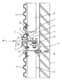
図5は上記スパンドレル用ボーダーAを並列して張設されるスパンドレルの中継部に配置して、両側のスパンドレル2の端部を支承させるものであって、下地材部4とボーダー部5との境部6の両側に突片7を設けられており、下地部材4の後端部の両側にT字溝9を設けられている。なお、このT字溝9は片側に設ける構成でも良い。   FIG. 5 shows the spandrel border A arranged in a spandrel relay portion stretched in parallel to support the end portions of the spandrel 2 on both sides. Protruding pieces 7 are provided on both sides of the boundary portion 6, and T-shaped grooves 9 are provided on both sides of the rear end portion of the base member 4. The T-shaped groove 9 may be provided on one side.

上記構成のスパンドレル用ボーダーAは、図6に示す通り、並列して張設されるスパンドレル2の中継部に合わせて取付部材3により建築物1に取り付けて、突片7、突片7に端部2aが乗るように建築物1にスパンドレル2の張設を行えば、両側のスパンドレル2、2の端部2aは突片7、突片7にそれぞれ支承されるので、端部2a、端部2aは突片7に取り付けられるカバー材11内に収まって外部から見えなくなるので、スパンドレル2の継ぎ目における端部2aの支承を外観が良く行われて、しかも、カバー材11による容入で浮遊状態の端部2aの支承が安定して行われる。   As shown in FIG. 6, the spandrel border A having the above-described configuration is attached to the building 1 with the attachment member 3 in accordance with the relay portion of the spandrel 2 stretched in parallel, and ends with the projecting piece 7 and the projecting piece 7. If the spandrel 2 is stretched on the building 1 so that the part 2a is placed, the end 2a of the spandrels 2 and 2 on both sides is supported by the projecting piece 7 and the projecting piece 7, respectively. Since 2a is contained in the cover material 11 attached to the projecting piece 7 and cannot be seen from the outside, the support of the end 2a at the joint of the spandrel 2 has a good appearance, and is in a floating state due to the insertion by the cover material 11 The end portion 2a is supported stably.

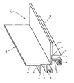
図7において符号Bは、請求項2に係るスパンドレル用ボーダーを示す。このスパンドレル用ボーダーBは、取付部材3を介して建築物1に取り付けられる下地材部4と、スパンドレル2の端部2aの目隠しを行うボーダー部5とが前後に連なって、両者の境部6付近にスパンドレル2の端部の裏面を支承するように突片7を有するように形成されるスパンドレル用ボーダーAの一対を、建築物1の目地部1a等に適合する間隔で並列するように連結板25で連結した構造にアルミニウム又はその合金の押出成形で形成したものであり、連結板25には建築物1に適合するように適当な意匠を施しておくことが好ましい。   In FIG. 7, reference numeral B denotes a spandrel border according to claim 2. In this spandrel border B, the base material part 4 attached to the building 1 via the attachment member 3 and the border part 5 for blindfolding the end 2a of the spandrel 2 are connected to each other in the front and rear, and the boundary part 6 between them. A pair of spandrel borders A formed so as to have a protruding piece 7 so as to support the back surface of the end portion of the spandrel 2 in the vicinity are connected so as to be juxtaposed at intervals suitable for the joint part 1a of the building 1 and the like. The structure connected by the plate 25 is formed by extrusion molding of aluminum or an alloy thereof, and the connection plate 25 is preferably provided with an appropriate design so as to be adapted to the building 1.

上記構成のスパンドレル用ボーダーBは、図8に示す通り一対のスパンドレル用ボーダーA、スパンドレル用ボーダーAを目地部1a等を挟むように建築物1に取付部材3、取付部材3で取り付けて、突片7、突片7に端部2a、端部2aが乗るように建築物1へスパンドレル2、スパンドレル2を張設すると、各スパンドレル2の端部2a、端部2aはスパンドレル用ボーダーA、スパンドレル用ボーダーAに設けられる突片7、突片7に支承させるので、両端部は突片7に取り付けられるカバー材11内にそれぞれ収まって外部より見えなくなるので、目地部1aに臨むスパンドレル2の端部2aの支承を外観が良く行われて、しかも、カバー材11による端部2aの容入で浮遊状態の端部2aの支承が安定して行われ、また、連結板25は目地部1a等を覆ってこれらの部分を飾り、意匠性を高める機能も果たす。   As shown in FIG. 8, the spandrel border B having the above-described configuration is attached to the building 1 with the attachment member 3 and the attachment member 3 so as to sandwich the joint portion 1a and the like. When span spans 2 and 2 are stretched on the building 1 so that the end 2a and the end 2a are placed on the piece 7 and the projecting piece 7, the end 2a and the end 2a of each span drel 2 are the border A for the span drel and the span drel. Since the projecting piece 7 provided on the border A is supported by the projecting piece 7, both end portions are respectively accommodated in the cover material 11 attached to the projecting piece 7 and cannot be seen from the outside, so the end of the spandrel 2 facing the joint portion 1 a The support of the portion 2a has a good appearance, and the support of the end portion 2a in a floating state is stably performed by the insertion of the end portion 2a by the cover material 11, and the connecting plate 25 Covers the joints 1a and the like and decorates these parts, and also fulfills the function of enhancing the design.

上記スパンドレル用ボーダーBの形成は、上述した通り一対のスパンドレル用ボーダーA、スパンドレル用ボーダーAが連結板25で連結されるようにアルミニウム又はその合金の押出成形することなく、図5に示す通り形成されたスパンドレル用ボーダーAの一対を、対応する突片7、突片7に図9に示す通り別に形成した連結板25の端部を重ねて、図9の円内に示す通り連結板25にあけた孔26から突片7にあけた下孔27へビス28を捻じ込んで結合することで形成してもよいもので、この場合は、幅寸法や意匠が異なる幾種類もの連結板25を準備して、これら連結版25を状況に応じて選択使用すると、目地部等の幅寸法の変化に安価で対応したり、目地部の意匠を建築物に合わせて変更したりすることができる等の利便性がある。   The spandrel border B is formed as shown in FIG. 5 without extruding aluminum or its alloy so that the pair of spandrel border A and spandrel border A are connected by the connecting plate 25 as described above. The pair of spandrel borders A formed on the corresponding projecting piece 7 and the projecting piece 7 are overlapped on the connecting plate 25 as shown in the circle of FIG. It may be formed by screwing and connecting a screw 28 to a lower hole 27 formed in the projecting piece 7 from the opened hole 26. In this case, various kinds of connecting plates 25 having different width dimensions and designs are provided. When these prepared connecting plates 25 are selected and used according to the situation, it is possible to cope with a change in the width dimension of the joint portion at a low cost, or to change the design of the joint portion according to the building, etc. The convenience of That.

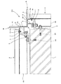
図10、図11において符号C1は、請求項3に係るスパンドレル用ボーダーを示す。このスパンドレル用ボーダーC1は、取付部材3を介して建築物1に取り付けられる下地材部4と、スパンドレル2の端部2aの目隠しを行うボーダー部5とが前後に連なって、両者の境部6付近にスパンドレル2の端部2aの裏面を支承するように突片7を有するように形成されるスパンドレル用ボーダーAの一対を、下地材部4の後端で直交するように連結した構造にアルミニウム又はその合金の押出成形で形成したものであり、下地部材4の後部に設けられるT字溝9は、持出片29で下地部材4よりも離隔されるように設けられる。   10 and 11, reference numeral C1 denotes a spandrel border according to claim 3. In the border C1 for the spandrel, the base material part 4 attached to the building 1 via the attachment member 3 and the border part 5 for blindfolding the end 2a of the spandrel 2 are connected to each other in the front and rear, and the boundary part 6 between them. Aluminum having a structure in which a pair of spandrel borders A formed so as to have a projecting piece 7 so as to support the back surface of the end 2a of the spandrel 2 in the vicinity is connected perpendicularly at the rear end of the base material part 4. Alternatively, it is formed by extrusion molding of the alloy, and the T-shaped groove 9 provided in the rear portion of the base member 4 is provided so as to be separated from the base member 4 by the take-out piece 29.

上記構成のスパンドレル用ボーダーC1は、図11に示す通り一対のスパンドレル用ボーダーA、スパンドレル用ボーダーAを下地材部4、下地材部4の後端の接合部が建築物1の出隅1bに対応するように取付部材3、取付部材3で建築物1に取り付けて、各々の突片7、突片7に端部2aが乗るように建築物1の2面にスパンドレル2、スパンドレル2を張設して、各々の端部2aを突片7、突片7に支承させ、端部2a、端部2aをビス18で突片7に締め付けると、スパンドレル2、スパンドレル2の端部2a、端部2aは突片7、突片7に支持される。なお、スパンドレル2の端部2aに、図1、図8等に示す通り、突片7、突片7にカバー材11、カバー材11を取り付けてこれらカバー材11、カバー材11に端部2aを容入させて化粧してもよい。   As shown in FIG. 11, the spandrel border C <b> 1 having the above-described configuration has a pair of spandrel border A, spandrel border A as the base material portion 4, and a joint portion at the rear end of the base material portion 4 at the corner 1 b of the building 1 Attached to the building 1 with the mounting member 3 and the mounting member 3 so as to correspond to each other, the spandrel 2 and the spandrel 2 are stretched on the two surfaces of the building 1 so that the end 2a is placed on each of the protruding pieces 7 and 7 The end 2a is supported by the projecting piece 7 and the projecting piece 7, and the end 2a and the end 2a are fastened to the projecting piece 7 with a screw 18. The part 2 a is supported by the projecting piece 7 and the projecting piece 7. In addition, as shown in FIG. 1, FIG. 8, etc., the cover member 11 and the cover material 11 are attached to the end piece 2a of the spandrel 2, and the cover member 11 and the cover member 11 are attached to the end portion 2a. You may make up with makeup.

図12、図13において符号C2は、請求項3に係るスパンドレル用ボーダーの他の例を示す。このスパンドレル用ボーダーC2は、取付部材3を介して建築物1に取り付けられる下地材部4と、スパンドレル2の端部2aの目隠しを行うボーダー部5とが前後に連なって、両者の境部6付近にスパンドレル2の端部2aの裏面を支承するように突片7を有するように形成されるスパンドレル用ボーダーAの一対を、ボーダー部5、ボーダー部5の先端で直交するように連結した構造にアルミニウム又はその合金の押出成形で形成されるものである。   12 and 13, reference numeral C <b> 2 indicates another example of the spandrel border according to claim 3. In this spandrel border C2, the base material part 4 attached to the building 1 via the attachment member 3 and the border part 5 for blindfolding the end part 2a of the spandrel 2 are connected to each other in the front and rear, and the boundary part 6 between them. A structure in which a pair of spandrel borders A formed so as to have a projecting piece 7 so as to support the back surface of the end 2a of the spandrel 2 in the vicinity is connected so as to be orthogonal to each other at the border 5 and the tip of the border 5 And formed by extrusion molding of aluminum or an alloy thereof.

上記構成のスパンドレル用ボーダーC2は、図13に示す通り一対のスパンドレル用ボーダーA、スパンドレル用ボーダーAをボーダー5、ボーダー5の先端の接合部が建築物1の入隅1cへ対応するように取付部材3、取付部材3で建築物1に取り付けて、各々の突片7、突片7に端部2aが乗るように建築物1の2面にスパンドレル2、スパンドレル2を張設する。そして、各々の端部2aを突片7、突片7に支承させ、端部2a、端部2aをビス18で突片7へ締め付けると、スパンドレル2、スパンドレル2の端部2a、端部2aは突片7、突片7に支持される。なお、スパンドレル2の端部2aに、図1、図8等に示す通り、突片7、突片7にカバー材11、カバー材11を取り付けてこれらカバー材11、カバー材11に端部2aを容入させて化粧してもよい。 As shown in FIG. 13, the spandrel border C <b> 2 having the above-described configuration is configured such that a pair of spandrel border A, the border A for spandrel A corresponds to the border portion 5, and the joint portion at the tip of the border portion 5 corresponds to the corner 1 c of the building 1. Are attached to the building 1 with the mounting member 3 and the mounting member 3, and the spandrel 2 and the spandrel 2 are stretched on the two surfaces of the building 1 so that the end 2 a is placed on each of the protruding pieces 7 and the protruding pieces 7. Then, when each end 2a is supported on the projecting piece 7 and the projecting piece 7, and the end 2a and the end 2a are fastened to the projecting piece 7 with a screw 18, the end 2a and end 2a of the span drel 2 and the span drel 2 are secured. Is supported by the projecting piece 7. As shown in FIG. 1 and FIG. You may make up with makeup.

本発明は、建築物に張設されるスパンドレルの端部、中継部、目地部、出隅、入隅等のコーナー部等において端部の支承と小口隠しの処理を簡便に高い意匠性をもって行うのに有効利用できる。   The present invention performs end support and small cover concealment easily and with high design at the end of a spandrel stretched on a building, a relay part, a joint part, a protruding corner, a corner part such as an entrance corner, etc. It can be used effectively.

請求項1に係るスパンドレル用ボーダーの使用態様を示す一部分の平面図。The partial top view which shows the usage condition of the border for spandrels which concerns on Claim 1. 同上スパンドレル用ボーダーの一部分を示す斜視図。The perspective view which shows a part of border for spandrel same as the above. 同上スパンドレル用ボーダーの突片に取り付けるカバー材の一部分を示す斜視図。The perspective view which shows a part of cover material attached to the protrusion of the border for spandrel same as the above. 同上スパンドレル用ボーダーを建築物に取り付ける取付部材の斜視図。The perspective view of the attachment member which attaches the border for spandrels to a building same as the above. 請求項1に係るスパンドレル用ボーダーの変形例の一部分を示す斜視図。The perspective view which shows a part of modification of the border for spandrels which concerns on Claim 1. 同上ボーダーの仕様態様を示す一部分の平面図。The top view of the part which shows the specification aspect of a border same as the above. 請求項2に係るスパンドレル用ボーダーの一部分を示す斜視図。The perspective view which shows a part of border for spandrels which concerns on Claim 2. 同上スパンドレル用ボーダーの使用態様を示す一部分の平面図。The partial top view which shows the usage condition of the border for spandrel same as the above. 同上スパンドレル用ボーダーの変形例を示す一部分の斜視図。The partial perspective view which shows the modification of the border for spandrel same as the above. 請求項3に係るスパンドレル用ボーダーの一例の一部分を示す斜視図。The perspective view which shows a part of example of the border for spandrels which concerns on Claim 3. 同上スパンドレル用ボーダーの仕様態様を示す一部分の平面図。The partial top view which shows the specification aspect of the border for spandrel same as the above. 請求項3に示すスパンドレル用ボーダーの他の例の一部分を示す斜視図。The perspective view which shows a part of other example of the border for spandrels shown in Claim 3. 同上スパンドレル用ボーダーの仕様態様を示す一部分の平面図。The partial top view which shows the specification aspect of the border for spandrel same as the above.

A スパンドレル用ボーダー
1 建築物
2 スパンドレル
3 取付部材
4 下地材部
5 ボーダー部
6 境部
7 突片
A Spandrel border 1 Building 2 Spandrel 3 Mounting member 4 Base material part 5 Border part 6 Boundary part 7 Projection piece

Claims (4)

建築物に外装されるスパンドレルの端部の支承と目隠しを行うスパンドレル用ボーダーであって、
このボーダーは、取付部材を介して建築物に取り付けられる下地材部と、スパンドレルの端縁の目隠しを行うボーダー部とが前後に連なって、両者の境部付近にはスパンドレルの端部の裏面を浮遊状態で支承するよう突片が一体形成されていることを特徴とするスパンドレル用ボーダー。
A spandrel border that supports and blindfolds the end of a spandrel that is externally mounted on a building,
In this border, the base material part that is attached to the building via the attachment member and the border part that blinds the end edge of the spandrel are connected to each other in front and back, and the back side of the end part of the spandrel is placed near the boundary part of both. A spandrel border characterized in that the projecting piece is integrally formed to be supported in a floating state .
請求項1において、取付部材を介して建築物に取り付けられる下地材部と、スパンドレルの端縁の目隠しを行うボーダー部とが前後に連なって、両者の境部付近にスパンドレルの端部の裏面を浮遊状態で支承するように突片が一体形成されるボーダーの一対が、建築物の目地等に適合する間隔で並列するように連結で接合一体化されていることを特徴とするスパンドレル用ボーダー。 In Claim 1, the base material part attached to a building via an attachment member, and the border part which performs blindfolding of the edge of a spandrel are connected back and forth, and the back surface of the end part of a spandrel is near the boundary part of both. A spandrel border characterized in that a pair of borders on which projecting pieces are integrally formed so as to be supported in a floating state are joined and integrated with a connecting plate so as to be arranged in parallel at intervals suitable for joints of a building. . 請求項1において、取付部材を介して建築物に取り付けられる下地材部と、スパンドレルの端縁の目隠しを行うボーダー部とが前後に連なって、両者の境部付近にスパンドレルの端部の裏面を浮遊状態で支承するように突片が一体形成されるボーダーの一対が、建築物のコーナー部に適合する角度で交叉するように下地材部又はボーダー部の端部の接合で一体化されていることを特徴とするスパンドレル用ボーダー。 In Claim 1, the base material part attached to a building via an attachment member, and the border part which performs blindfolding of the edge of a spandrel are connected back and forth, and the back surface of the end part of a spandrel is near the boundary part of both. A pair of borders with which the projecting pieces are integrally formed so as to be supported in a floating state are integrated by joining the base material part or the edge part of the border part so as to cross at an angle suitable for the corner part of the building. A border for spandrel. 請求項1〜請求項3の何れかにおいて、取付部材を介して建築物に取り付けられる下地材部と、スパンドレルの端縁の目隠しを行うボーダー部とが前後に連なって、両者の境部付近にスパンドレルの端部の裏面を浮遊状態で支承するように突片が一体形成されるボーダーが、上記突片にスパンドレルの端部を容入するカバー材を取り付けられていることを特徴とするスパンドレル用ボーダー。 In any one of Claims 1-3, the base material part attached to a building via an attachment member, and the border part which blindfolds the edge of a spandrel are connected back and forth, and the boundary part of both is near. For spandrel, the border on which the projecting piece is integrally formed so as to support the back surface of the end of the spandrel in a floating state is attached to the projecting piece to cover the end of the spandrel. border.
JP2008087546A 2008-03-28 2008-03-28 Spandrel border Active JP5358815B2 (en)

Priority Applications (1)

Application Number Priority Date Filing Date Title
JP2008087546A JP5358815B2 (en) 2008-03-28 2008-03-28 Spandrel border

Applications Claiming Priority (1)

Application Number Priority Date Filing Date Title
JP2008087546A JP5358815B2 (en) 2008-03-28 2008-03-28 Spandrel border

Publications (2)

Publication Number Publication Date
JP2009243049A JP2009243049A (en) 2009-10-22
JP5358815B2 true JP5358815B2 (en) 2013-12-04

Family

ID=41305259

Family Applications (1)

Application Number Title Priority Date Filing Date
JP2008087546A Active JP5358815B2 (en) 2008-03-28 2008-03-28 Spandrel border

Country Status (1)

Country Link
JP (1) JP5358815B2 (en)

Families Citing this family (1)

* Cited by examiner, † Cited by third party
Publication number Priority date Publication date Assignee Title
JP5388957B2 (en) * 2010-06-28 2014-01-15 株式会社Lixil Solar heat collecting wall device

Family Cites Families (6)

* Cited by examiner, † Cited by third party
Publication number Priority date Publication date Assignee Title
JPS6013956Y2 (en) * 1980-03-31 1985-05-04 理研軽金属工業株式会社 spandrel
JPS62176335U (en) * 1986-04-28 1987-11-09
JP3083966B2 (en) * 1994-12-07 2000-09-04 西本金属工業株式会社 Spandrel
JPH10121712A (en) * 1996-10-18 1998-05-12 Pilot Corp:The Mounting structure of wall trim
JPH11324198A (en) * 1998-05-12 1999-11-26 Ykk Architectural Products Inc Wall body support device
JP3921400B2 (en) * 2002-03-04 2007-05-30 三協立山アルミ株式会社 curtain wall

Also Published As

Publication number Publication date
JP2009243049A (en) 2009-10-22

Similar Documents

Publication Publication Date Title
JP2007202992A (en) Front door for game board
KR101099373B1 (en) Connection Structure of assembled panel
JP2011094344A (en) External facing louver for building
JP5358815B2 (en) Spandrel border
JP2005179987A (en) Exterior wall reform structure
KR100954551B1 (en) Device for catching corner of fire prevention unit frame
JP3630094B2 (en) Glass panel system
JPH10299222A (en) Decorative structure of external wall
JP2006249845A (en) Door
JP2009167649A (en) Vertical multiple window
JP3940347B2 (en) Frame device
KR20110006691U (en) Connecting structure of a panel with a fastener
CN217537648U (en) Wave plate interior wall with LED display screen
USD603060S1 (en) Architectural panel with leaves design
JP5377929B2 (en) Wall panel of bathroom wall and bathroom unit in bathroom unit
JP4044465B2 (en) outer wall
JP2006249911A (en) Temporary enclosure board
JP3969353B2 (en) Wall panel connection structure
JP6795724B2 (en) Eaves roof parting member and eaves structure
JP3126105U (en) Opening frame for wall opening
JPH0135912Y2 (en)
JPS6212019Y2 (en)
JP4276093B2 (en) Windbreak installation structure
JP4918531B2 (en) Joinery
JP2004332439A (en) Door for furniture

Legal Events

Date Code Title Description
A621 Written request for application examination

Free format text: JAPANESE INTERMEDIATE CODE: A621

Effective date: 20100519

A977 Report on retrieval

Free format text: JAPANESE INTERMEDIATE CODE: A971007

Effective date: 20120327

A131 Notification of reasons for refusal

Free format text: JAPANESE INTERMEDIATE CODE: A131

Effective date: 20120605

A521 Written amendment

Free format text: JAPANESE INTERMEDIATE CODE: A523

Effective date: 20120806

TRDD Decision of grant or rejection written
A01 Written decision to grant a patent or to grant a registration (utility model)

Free format text: JAPANESE INTERMEDIATE CODE: A01

Effective date: 20130806

A61 First payment of annual fees (during grant procedure)

Free format text: JAPANESE INTERMEDIATE CODE: A61

Effective date: 20130809

R150 Certificate of patent or registration of utility model

Ref document number: 5358815

Country of ref document: JP

Free format text: JAPANESE INTERMEDIATE CODE: R150

Free format text: JAPANESE INTERMEDIATE CODE: R150

R250 Receipt of annual fees

Free format text: JAPANESE INTERMEDIATE CODE: R250

R250 Receipt of annual fees

Free format text: JAPANESE INTERMEDIATE CODE: R250

R250 Receipt of annual fees

Free format text: JAPANESE INTERMEDIATE CODE: R250

R250 Receipt of annual fees

Free format text: JAPANESE INTERMEDIATE CODE: R250

R250 Receipt of annual fees

Free format text: JAPANESE INTERMEDIATE CODE: R250

R250 Receipt of annual fees

Free format text: JAPANESE INTERMEDIATE CODE: R250