JP5352785B2 - Cast iron casting method, feeder, mold and mold making method - Google Patents
Cast iron casting method, feeder, mold and mold making method Download PDFInfo
- Publication number
- JP5352785B2 JP5352785B2 JP2009101428A JP2009101428A JP5352785B2 JP 5352785 B2 JP5352785 B2 JP 5352785B2 JP 2009101428 A JP2009101428 A JP 2009101428A JP 2009101428 A JP2009101428 A JP 2009101428A JP 5352785 B2 JP5352785 B2 JP 5352785B2
- Authority
- JP
- Japan
- Prior art keywords
- pressure
- molten metal
- cast iron
- mold
- casting
- Prior art date
- Legal status (The legal status is an assumption and is not a legal conclusion. Google has not performed a legal analysis and makes no representation as to the accuracy of the status listed.)
- Expired - Fee Related
Links
Images


Abstract
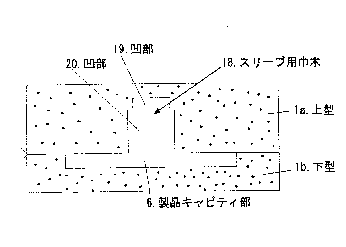
Description
本発明は、鋳鉄鋳造において発生する「型張り」、「収縮巣」(引け巣ともいう)、及び「焼付き」等を防止する鋳造方法、その実施に用いる押湯部、その押湯部をもつ鋳型、及びその鋳型の造型方法に関するもので、押湯の内で埋込み型押湯(盲押湯ともいう)に属する技術に特徴を有するものである。 The present invention relates to a casting method for preventing “stretching”, “shrinkage nest” (also referred to as shrinkage nest), “seizure nest”, etc., which occurs in cast iron casting, a feeder part used for the implementation, and a feeder part thereof. The present invention relates to a mold having a mold and a molding method of the mold, and is characterized by a technique belonging to an embedded type hot water (also referred to as a blind hot water).
鋳造において、金属は一般に凝固時に収縮を伴うため、良好な湯口方案で完全に鋳型内を溶湯で満たしても、凝固後の鋳物には「収縮巣」が生じることになる。その防止のために、液体収縮と凝固収縮とで不足する溶湯を補う押湯が必要となるので、そのための手段(以下押湯部という)の設置が不可欠となっている。押湯を用いない方法も提案されているが(例えば特開平10−85924号公報参照)、造型作業や鋳造後の砂との分離に手間がかかる。 In casting, metal generally shrinks during solidification, so that even if the mold is completely filled with molten metal using a good pouring method, a “shrinkage nest” occurs in the cast after solidification. In order to prevent this, it is necessary to provide a hot water supply that compensates for the lack of molten metal due to the liquid shrinkage and the solidification shrinkage. A method that does not use a feeder is also proposed (see, for example, Japanese Patent Application Laid-Open No. 10-85924), but it takes a lot of time to perform molding work and separation from sand after casting.
そこで、押湯を用いる方法が一般的に行われているが、特に鋳鉄は凝固時に黒鉛が晶出することで、他の金属や合金に比べて凝固収縮率は小さいけれども、黒鉛の晶出による溶湯の体積膨張が大きい。そのため、鋳鉄を用いる鋳造では押湯部の設置方法や大きさ等が他金属や合金の鋳物鋳造と異なることになる。 Therefore, although a method using a feeder is generally used, cast iron, in particular, has a solidification shrinkage rate smaller than that of other metals and alloys due to the crystallization of graphite during solidification. Large volume expansion of molten metal. Therefore, in casting using cast iron, the installation method and size of the feeder are different from those of other metals or alloys.
押湯部の設置方法を大別すると、開放型押湯と非開放型即ち埋込み型押湯がある。前者は、図11で示したような構造で密閉状態でないため、溶湯の体積膨張や鋳物砂の体積膨張(キャビティ容積の減少)により、溶湯圧力が増加しようとしても溶湯の圧力増加分は開放型押湯部の開放部分へ逃げる。そのため、鋳型内の溶湯圧力を増加させることがなくて、鋳型の軟弱な部分を変形させるようなことは少ないが、上部からの放熱があるので、押湯量を多くするか、又はフリカケ保温剤にて押湯表面を保温する必要がある等の問題点がある。 The installation method of the feeder is roughly divided into an open-type feeder and a non-open type, that is, an embedded-type feeder. Since the former is not sealed in the structure as shown in FIG. 11, even if the molten metal pressure increases due to the volume expansion of the molten metal or the volume expansion of the foundry sand (decrease in the cavity volume), the increased pressure of the molten metal is an open type. Escape to the open part of the feeder. Therefore, it does not increase the molten metal pressure in the mold and rarely deforms the soft part of the mold, but since there is heat radiation from the upper part, the amount of hot water is increased or the flickering heat retention agent is used. There is a problem that it is necessary to keep the hot water surface warm.
他方、後者の埋込み型押湯は、図12で示したような構造で密閉状態であるが故に、溶湯の体積膨張と鋳物砂の体積膨張が鋳型内の溶湯圧力を増加させて、鋳型の軟弱な部分を変形させることが多い。密閉された鋳型内での溶湯圧力の増加が想像以上に強大であることは、鋳造現場でよく知られていることである。溶湯の増加圧力によるこの現象を、上記の「型張り」と称し、鋳物製品の寸法不良をもたらすだけでなく、鋳物製品に「収縮巣」を発生させて、製品不良の要因となっている。 On the other hand, since the latter embedded mold feeder has a structure as shown in FIG. 12 and is in a sealed state, the volume expansion of the molten metal and the volume expansion of the foundry sand increase the molten metal pressure in the mold, and the softness of the mold is reduced. Often, this part is deformed. It is well known at the casting site that the increase in melt pressure in a sealed mold is stronger than expected. This phenomenon due to the increased pressure of the molten metal is referred to as the above-mentioned “molding”, which not only causes a dimensional defect of the cast product, but also causes a “shrinkage nest” in the cast product, thereby causing a product defect.
また、「型張り」が生じない強固な鋳型とした場合には、溶湯の体積膨張と鋳物砂の体積膨張により鋳型内の溶湯圧力が強まって、鋳型の形状によっては鋳型の砂粒間に溶湯がしみ込み、上記「焼付き」現象が生じることになる。 In the case of a strong mold that does not cause “mold tension”, the molten metal pressure in the mold increases due to the volume expansion of the molten metal and the volume expansion of the foundry sand. The above-mentioned “burn-in” phenomenon occurs.
それでは、圧力を逃がして不良品の発生を防止するために、開放型押湯にすればよいとも考えられる。しかし上記問題点の外に、鋳型の造形は手込めによる場合は勿論のこと、生型自動造型機によっても鋳型の強度を強めるのに上型側から油圧等で圧力を加える必要があるため、開放型押湯部の設置には手数がかかる。 Then, in order to relieve pressure and prevent generation | occurrence | production of inferior goods, it is thought that what is necessary is just to use an open type feeder. However, in addition to the above problems, it is necessary to apply pressure by hydraulic pressure etc. from the upper mold side in order to increase the strength of the mold even by molding automatic molding machine as well as molding by mold, It takes time to install the open-type feeder.
これらの事柄に関しては、後記非特許文献1や、非特許文献2等が、鋳造工学や鋳鉄鋳物に関して詳しく記載された文献で、開放型押湯や埋込み型押湯の長所・欠点等についても詳しい記載がある。 Regarding these matters, Non-Patent Document 1 and Non-Patent Document 2, which will be described later, are documents that have been described in detail regarding casting engineering and cast iron castings, and are also familiar with the advantages and disadvantages of open-type and embedded-type feeders. There is a description.
必ずしも鋳鉄鋳物に関するものではないが、鋳造における問題点の解決のために特許出願されたものとして、以下のようなものがある。 Although not necessarily related to cast iron castings, patent applications for solving problems in casting include the following.
その他、鋳鉄の鋳造技術で押湯部を有するものに関する特許文献には、クルマのホイール、クローラ車両のトラックシューあるいはディーゼル車両のシリンダピストンの鋳造のように、特殊な製品に限定される技術に関して、例えば次のようなものもある。
ところが、上記従来から行われている方法や先行技術文献に記載の方法は、開放型押湯と非開放型即ち埋込み型押湯とは、それぞれ上記の問題点を有している。また上記各特許文献に記載のものは、用途が限定されると共に、押湯部に冷却回路や加熱回路、圧縮ガスの送気手段等の特別な付属装置を設ける必要があり、構造が大型化したり複雑化したりする。 However, in the conventional methods and the methods described in the prior art documents, the open-type feeder and the non-open type, that is, the embedded-type feeder have the above-mentioned problems. In addition, those described in each of the above patent documents are limited in application, and it is necessary to provide a special accessory device such as a cooling circuit, a heating circuit, and a compressed gas supply means in the feeder part, and the structure becomes large. Or complicated.
本発明は、上記問題点の解消を課題として鋭意検討を重ねた結果、完成を得たものである。その目的とするところは、開放型押湯と埋込み型押湯がもつ双方の長所を生かし、互いの欠点を克服し、シンプルな構成で装置が大型化したり複雑化することなく、鋳型の造型が安易であると共に、型張り・収縮巣・焼付き等の発生を低減でき、かつ押湯の保温性も向上させることができる鋳鉄用鋳造方法、それに使用する押湯部、その押湯部をもつ鋳型、及びその鋳型の造型方法を提供することにある。 The present invention has been completed as a result of intensive studies aimed at solving the above problems. The purpose is to make use of the advantages of both open-type and embedded-type hot springs, overcoming each other's drawbacks, and making molds with a simple configuration without increasing the size and complexity of the equipment. It has a casting method for cast iron that is easy and can reduce the occurrence of mold tension, shrinkage nest, seizure, etc., and can also improve the heat retaining property of the feeder, and has a feeder part and its feeder part. An object of the present invention is to provide a mold and a method for forming the mold.
A.本発明に係る鋳鉄鋳造方法は、
埋込み型押湯部2をもつ鋳型1を用いるものであり、
上型1a内で製品キャビティ部6と連通する押湯部2を、
本来の押湯効果を発揮するための溶湯充満部3と、その外部にあって、鋳鉄溶湯の凝固時に発生する増加圧力吸収用の圧力吸収部4とで構成すると共に、
溶湯充満部3と圧力吸収部4との間に、溶湯充満部3内が一定圧を越えた際にその増加圧力で圧力吸収部4側へ膨出可能又は割れて開口可能な隔壁5を設けておき、
溶湯充満部3内へ鋳鉄溶湯を注湯して、その凝固時に溶湯充満部3内に発生した溶湯の増加圧力を圧力吸収部4へ逃がすことにより、製品キャビティ部6に過度の圧力が加わらぬようにして鋳造するものである。
A. The cast iron casting method according to the present invention is:
A mold 1 having an embedded mold feeder 2 is used.
In the upper mold 1a, the feeder part 2 communicating with the product cavity part 6 is
The molten metal filling part 3 for demonstrating the original hot metal effect and the pressure absorbing part 4 for absorbing the increased pressure generated when the cast iron molten metal is solidified,
A partition wall 5 is provided between the molten metal filling portion 3 and the pressure absorbing portion 4 so that when the inside of the molten metal filling portion 3 exceeds a certain pressure, it can be expanded or cracked to open to the pressure absorbing portion 4 side with the increased pressure. Leave
By pouring molten cast iron into the molten metal filling portion 3 and releasing the increased pressure of the molten metal generated in the molten metal filling portion 3 during solidification to the pressure absorbing portion 4, excessive pressure is not applied to the product cavity portion 6. In this way, casting is performed.
B.本発明に係る鋳鉄鋳造方法の実施に用いる押湯部の第1は、
埋込み型の押湯部2であって、
鋳鉄溶湯を充満させる製品キャビティ部6に連通する如く設ける該押湯部2として、
本来の押湯効果を発揮するための溶湯充満部3と、その外部に、鋳鉄溶湯の凝固時の溶湯の増加圧力吸収用の圧力吸収部4を設けると共に、
溶湯充満部3と圧力吸収部4との間に、溶湯充満部3内が一定圧を越えた際にその増加圧力で圧力吸収部4側へ膨出可能又は割れて開口可能な隔壁5を設けたものである。
B. The first of the feeder parts used for carrying out the cast iron casting method according to the present invention is:
It is an embedded type feeder section 2,
As the hot water supply part 2 provided so as to communicate with the product cavity part 6 filled with cast iron melt,
While providing a molten metal filling portion 3 for demonstrating the original hot metal effect, and a pressure absorbing portion 4 for absorbing the increased pressure of the molten metal at the time of solidification of the cast iron melt,
A partition wall 5 is provided between the molten metal filling portion 3 and the pressure absorbing portion 4 so that when the inside of the molten metal filling portion 3 exceeds a certain pressure, it can be expanded or cracked to open to the pressure absorbing portion 4 side with the increased pressure. It is a thing.
C.本発明に係る鋳鉄鋳造方法の実施に用いる押湯部の第2は、
埋込み型の押湯部2であって、
鋳鉄溶湯を充満する製品キャビティ部6に連通する如く設ける該押湯部2を、
本来の押湯効果を発揮するための溶湯充満部3と、その外部に、鋳鉄溶湯の凝固時の溶湯の増加圧力吸収用の圧力吸収部4を設けると共に、
溶湯充満部3と圧力吸収部4との間に、溶湯充満部3内が一定圧を越えた際にその増加圧力で圧力吸収部4側へ膨出可能又は割れて開口可能な隔壁5を設け、
かつ該隔壁5の上部に、熱で消失可能な材質製の部材17を設置して、その消失で形成される空所が上記圧力吸収部4となるようにしたものである。
C. The second of the feeder part used for carrying out the cast iron casting method according to the present invention is:
It is an embedded type feeder section 2,
The feeder part 2 provided so as to communicate with the product cavity part 6 filled with molten cast iron,
While providing a molten metal filling portion 3 for demonstrating the original hot metal effect, and a pressure absorbing portion 4 for absorbing the increased pressure of the molten metal at the time of solidification of the cast iron melt,
A partition wall 5 is provided between the molten metal filling portion 3 and the pressure absorbing portion 4 so that when the inside of the molten metal filling portion 3 exceeds a certain pressure, it can be expanded or cracked to open to the pressure absorbing portion 4 side with the increased pressure. ,
In addition, a member 17 made of a material that can be lost by heat is installed on the upper portion of the partition wall 5 so that a space formed by the disappearance becomes the pressure absorbing portion 4.
D.本発明に係る鋳鉄鋳造方法の実施に用いる押湯部の第3は、
埋込み型の押湯部2であって、
鋳鉄溶湯を充満する製品キャビティ部6に連通する如く設ける該押湯部2を、
本来の押湯効果を発揮するための溶湯充満部3と、該溶湯充満部3内が一定圧を越えた際にその増加圧力で後記凹部19側へ膨出可能又は開口可能な隔壁5とを設けたものにすると共に、
鋳型1内で上記隔壁5の外方に当たる箇所に圧力吸収部用の凹部19を予め形成したものとし、
鋳鉄溶湯の凝固時の溶湯の増加圧力を、隔壁5を経て上記凹部19による圧力吸収部4へ逃がし得るようにしたものである。
D. The third of the feeder part used for carrying out the cast iron casting method according to the present invention is:
It is an embedded type feeder section 2,
The feeder part 2 provided so as to communicate with the product cavity part 6 filled with molten cast iron,
A molten metal filling portion 3 for exhibiting the original hot metal effect, and a partition wall 5 capable of bulging or opening to the concave portion 19 described later with the increased pressure when the inside of the molten metal filling portion 3 exceeds a certain pressure. As well as
It is assumed that a concave portion 19 for a pressure absorbing portion is formed in advance at a location that contacts the outside of the partition wall 5 in the mold 1.
The increased pressure of the molten metal at the time of solidification of the cast iron melt can be released to the pressure absorbing portion 4 by the concave portion 19 through the partition wall 5.
E.本発明に係る鋳鉄鋳造方法の実施に用いる鋳型は、
埋込み型の押湯部2をもつ鋳型1であって、
鋳鉄溶湯を充満させる製品キャビティ部6に連通する如く押湯部2を設け、
その押湯部として、上記第1の押湯部2、第2の押湯部2、又は第3の押湯部を用いるようにしたものである。
E. The mold used for carrying out the cast iron casting method according to the present invention is:
A mold 1 having an embedded hot-water feeder 2,
The hot water supply part 2 is provided so as to communicate with the product cavity part 6 filled with the molten cast iron,
As the feeder, the first feeder 2, the second feeder 2, or the third feeder is used.
F.本発明に係る鋳鉄鋳造方法の実施に用いる鋳型の造型方法の第1は、
予め形成しておいた上記第1の押湯部2又は第2の押湯部2を、鋳型1内に載置して鋳物砂を手込めで充填することにより、上型1aを形成するようにしたものである。
F. The first of the mold making methods used for carrying out the cast iron casting method according to the present invention is:
The upper die 1a is formed by placing the first feeder part 2 or the second feeder part 2 formed in advance in the mold 1 and filling it with casting sand by hand. It is a thing.
G.本発明に係る鋳鉄鋳造方法の実施に用いる鋳型の造型方法の第2は、
生型自動造型機による造型にて予め鋳型1内に、スリーブ挿入用の空所であるスリーブ用巾木18を形成しておき、
そのスリーブ用巾木18内に、予め溶湯充満部3と圧力吸収部4と、両者3,4間に溶湯充満部3内が一定圧を越えた際にその増加圧力で圧力吸収部4側へ膨出又は開口可能な隔壁5とを設けたスリーブ2aを挿入することにより、
圧力吸収部4付きの押湯部2をもつ上型1aを造型するようにしたものである。
G. The second of the mold making methods used for carrying out the cast iron casting method according to the present invention is:
A sleeve base 18 which is a space for inserting a sleeve is formed in the mold 1 in advance by molding with a raw automatic molding machine,
In the sleeve skirting board 18, when the molten metal filling portion 3 exceeds a certain pressure between the molten metal filling portion 3 and the pressure absorption portion 4 and both 3 and 4, the increased pressure leads to the pressure absorption portion 4 side. By inserting a sleeve 2a provided with a partition wall 5 that can bulge or open,
The upper mold 1a having the feeder part 2 with the pressure absorbing part 4 is formed.
H.本発明に係る鋳鉄鋳造方法の実施に用いる鋳型の造型方法の第3は、
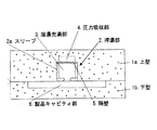
生型自動造型機による造型にて予め鋳型1内に、上部に圧力吸収部用の凹部19を、下部にスリーブ2aを挿入可能な凹部20を有するスリーブ用巾木18を形成しておき、
溶湯充満部3内が一定圧を越えた際にその増加圧力で上記凹部19側へ膨出可能又は開口可能な隔壁5を予め上部に形成したスリーブ2aを、上記スリーブ用巾木18内に挿入して、隔壁5上方の凹部19が圧力吸収部4となるようにすることにより、
圧力吸収部4付きの押湯部2をもつ上型1aを造型するようにしたものである。
H. The third of the mold making methods used for carrying out the cast iron casting method according to the present invention is:
A sleeve base plate 18 having a concave portion 19 for pressure absorption at the upper portion and a concave portion 20 into which the sleeve 2a can be inserted at the lower portion is formed in advance in the mold 1 by molding with an automatic molding machine.
When the inside of the molten metal filling part 3 exceeds a certain pressure, the sleeve 2a in which the partition wall 5 that can be expanded or opened to the concave part 19 side with the increased pressure is formed in the upper part is inserted into the sleeve base board 18 And by making the recessed part 19 above the partition 5 become the pressure absorbing part 4,
The upper mold 1a having the feeder part 2 with the pressure absorbing part 4 is formed.
上記の構成において、押湯部2とは単に円筒状のスリーブ2aを指すのではなく、溶湯充満部3と隣接して設けた圧力吸収部4とその間の隔壁5を含むものを指すものとする。圧力吸収部4の容積は、溶湯が膨張して増加した体積よりも大きめに形成しておくことは勿論である。隔壁5は鋳型1の強度よりも弱く形成して、鋳型1の損壊より先に隔壁5が膨出し、又は割れて開口7が形成されるようにしてある。該隔壁5は1枚でもよいし、2枚以上であってもよい。 In the above-described configuration, the hot metal part 2 does not simply indicate the cylindrical sleeve 2a but includes a pressure absorbing part 4 provided adjacent to the molten metal filling part 3 and a partition wall 5 therebetween. . Of course, the volume of the pressure absorption part 4 is made larger than the volume which the molten metal expanded and increased. The partition wall 5 is formed to be weaker than the strength of the mold 1 so that the partition wall 5 bulges or breaks before the mold 1 is broken to form the opening 7. The number of the partition walls 5 may be one, or two or more.
また該隔壁5が膨出する方向や開口7が形成される方向は、上方であればよいが(例えば図1ないし図8参照)、それに限らず側方でもよい。上記圧力吸収部4は、押湯部2内で溶湯充満部3に隣接して設けておく。熱で消失可能な材質製の部材17とは、例えば発砲スチロールのように熱で溶解し消失する材質で厚めの板状としたものが望ましい。なお隔壁5は、割れて開口可能にしてもよいし、圧力吸収部4又はそれ用の凹部19側へ膨出可能にしてもよい。 Further, the direction in which the partition wall 5 bulges and the direction in which the opening 7 is formed is only required to be upward (see, for example, FIGS. 1 to 8), but is not limited thereto and may be lateral. The pressure absorbing part 4 is provided adjacent to the molten metal filling part 3 in the feeder part 2. The member 17 made of a material that can be lost by heat is preferably a thick plate-like material that dissolves and disappears by heat, such as foamed polystyrene. Note that the partition wall 5 may be opened by being cracked, or may be bulged toward the pressure absorbing portion 4 or the recessed portion 19 therefor.
上記構成の本発明によれば、シンプルな構成ながら、鋳鉄鋳造において従来大きな問題である「型張り」、「収縮巣」及び「焼付き」等の発生を大幅に減少させて、良好な品質の鋳物製品16を製造することができるし、押湯の保温性も向上できる。
これを従来のものと対比しながら説明する。
According to the present invention having the above-described configuration, the occurrence of “mold tension”, “shrinkage nest”, “seizure”, and the like, which have been a major problem in cast iron casting, is greatly reduced while having a simple configuration. The cast product 16 can be manufactured, and the heat retaining property of the feeder can be improved.
This will be described in comparison with the conventional one.
埋込み型押湯は密閉状態であるが故に、溶湯の体積膨張と鋳物砂の体積膨張が鋳型内の溶湯圧力を増加させる。そのため、従来の埋込み型押湯をもつものでは、鋳型の軟弱な部分を変形させて「型張り」現象を生じ、鋳物製品の寸法不良をもたらしたり、鋳物製品に「収縮巣」を発生させて、製品不良の要因となっていた。 Since the buried type feeder is in a sealed state, the volume expansion of the molten metal and the volume expansion of the foundry sand increase the molten metal pressure in the mold. For this reason, with a conventional embedded mold feeder, the soft part of the mold is deformed, resulting in a “die tension” phenomenon, resulting in a defective dimension of the cast product, or a “shrinkage nest” in the cast product. Was a cause of product defects.
また「型張り」が生じない強固な鋳型でも、同じく溶湯の体積膨張と鋳物砂の体積膨張により鋳型内の溶湯圧力が強まり、鋳型の形状によっては鋳型の砂粒間に溶湯がしみ込んで、「焼付き」現象が発生していた。さらに、「収縮巣不良」(引け巣不良)が発生した場合には、押湯部を大きくするなどしてそれらの不良対策とすることが多く、それがさらに歩留率の悪化を招いていた。 Even in a strong mold that does not cause “mold tension”, the molten metal pressure in the mold increases due to the volume expansion of the molten metal and the volume expansion of the foundry sand. The “with” phenomenon occurred. In addition, when “shrinkage flaws” (shrinkage flaws) occur, they are often used as countermeasures for such flaws by enlarging the feeder, which further deteriorates the yield rate. .
これに対して本発明は、上記の如く、鋳型1内で製品キャビティ部6に連通する如く設けた埋込み型の押湯部2を、本来の押湯効果を発揮するための溶湯充満部3と、その内部の増加圧力吸収用の圧力吸収部4とで構成して、それらを隣接して設けると共に、溶湯充満部3と圧力吸収部4間に、溶湯充満部3内の増加圧力で圧力吸収部4側へ開口し、または膨出する隔壁5を設けたものである。 On the other hand, in the present invention, as described above, the embedded-type feeder 2 provided so as to communicate with the product cavity 6 in the mold 1 is replaced with the molten metal filling portion 3 for exhibiting the original feeder effect. The pressure absorbing portion 4 for absorbing the increased pressure inside thereof is provided adjacent to the pressure absorbing portion 4, and the pressure is absorbed by the increased pressure in the molten metal filling portion 3 between the molten metal filling portion 3 and the pressure absorbing portion 4. A partition wall 5 that opens or bulges toward the portion 4 is provided.
したがって、本発明によれば、
イ)埋込み型押湯式の長所をもつ鋳型1を、シンプルな構成により、従来法とほぼ同等のコストで容易・迅速に造型することができる。
Therefore, according to the present invention,
B) The mold 1 having the advantages of the embedded type hot-water type can be easily and quickly formed with a simple structure at a cost almost equal to that of the conventional method.
ロ)鋳鉄溶湯を製品キャビティ部6と共に押湯部2の溶湯充満部3へ充満させた際、溶湯の凝固による体積膨張と鋳物砂の体積膨張で鋳型1内の溶湯圧力が増加しても、隔壁5が圧力吸収部4側へ開口し、または圧力吸収部4側へ膨出し、または熱で溶解可能な材質の部材17が消失して圧力吸収部4を形成する(例えば図2,図3,図4参照)。そのため、溶湯充満部3の容積が増大することになり、溶湯による溶湯充満部3内の圧力を下げる。 B) When the molten cast iron is filled together with the product cavity portion 6 into the molten metal filling portion 3 of the feeder portion 2, even if the molten metal pressure in the mold 1 increases due to the volume expansion due to solidification of the molten metal and the volume expansion of the foundry sand, The partition wall 5 opens to the pressure absorbing portion 4 side, or bulges to the pressure absorbing portion 4 side, or the member 17 made of a material that can be dissolved by heat disappears to form the pressure absorbing portion 4 (for example, FIG. 2 and FIG. 3). FIG. 4). Therefore, the volume of the molten metal filling part 3 increases, and the pressure in the molten metal filling part 3 due to the molten metal is lowered.
ハ)それゆえ、密閉型の埋込み型押湯式でありながら、押湯部2や製品キャビティ部6に過度の圧力が加わらないから、鋳型1の軟弱な部分の変形・損壊を防止でき、鋳物製品16の寸法不良を無くし、また収縮巣の発生も押さえられて、良好な鋳物製品16を製造することができる。 C) Therefore, even though it is a sealed embedded feeder type, excessive pressure is not applied to the feeder part 2 and the product cavity part 6, so that deformation and breakage of the soft part of the mold 1 can be prevented. It is possible to manufacture a good casting product 16 by eliminating the dimensional defects of the product 16 and suppressing the generation of shrinkage foci.
ニ)また溶湯充満部3内の圧力が過大にならないので、鋳型1の砂粒間に溶湯がしみ込むことを防止でき、「焼付き」現象も無くすことができる。 D) Since the pressure in the molten metal filling portion 3 does not become excessive, it is possible to prevent the molten metal from infiltrating between the sand grains of the mold 1 and to eliminate the “seizure” phenomenon.
ホ)さらに、上方からの放熱を避けられるから、押湯の保温性を向上できて、押湯量を少なくして溶湯量が削減できる。それによって、製品の歩留り率を向上させることもできて、省エネ効果を発揮すると共に、ひいては環境問題にも寄与することができる。 E) Furthermore, since heat radiation from above can be avoided, the heat retaining property of the hot water can be improved, and the amount of molten metal can be reduced by reducing the amount of hot water. As a result, the yield rate of the product can be improved, and an energy saving effect can be exhibited and, in turn, it can contribute to environmental problems.
本発明は、製品キャビティ部6に連通する如く設けた押湯部2として、本来の押湯効果を発揮するための溶湯充満部3と、鋳鉄溶湯の凝固時の溶湯の増加圧力吸収用の圧力吸収部4を隣接して設けると共に、その間に設けた隔壁5を、溶湯充満部3内で一定圧を越えた際にその増加圧力で圧力吸収部4側へ開口7を形成し、又は圧力吸収部4側へ膨出し、あるいは熱で溶解可能な材質製の部材が熱で消失して圧力吸収部4が形成されるようにし、溶湯充満部3内の増加圧力を逃がすことにより、製品キャビティ部6に過度の圧力が加わらぬようにして鋳造する。 In the present invention, the feeder 2 provided to communicate with the product cavity portion 6 includes a molten metal filling portion 3 for exhibiting the original feeder effect, and a pressure for absorbing the increased pressure of the molten metal when the cast iron melt is solidified. The absorption part 4 is provided adjacently, and when the partition 5 provided therebetween exceeds a certain pressure in the molten metal filling part 3, an opening 7 is formed on the pressure absorption part 4 side with the increased pressure, or pressure absorption. The product cavity portion is formed by allowing the pressure absorbing portion 4 to be formed by swelling to the side of the portion 4 or by dissipating the member made of a material that can be melted by heat to form the pressure absorbing portion 4 and releasing the increased pressure in the molten metal filling portion 3. 6 is cast so that excessive pressure is not applied.
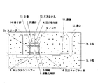
A.図1は、本発明の押湯部2の実施例を備えた鋳型1を示すものである。
この鋳型1は、公知のものと同様に上型1aと下型1bとからなるが、ここでの下型1bは手込め造型による生型とし、製品キャビティ部6としての凹所が形成されている。下型1bを生型としたのは、「型張り」が発生し易くするためである。
A. FIG. 1 shows a mold 1 provided with an embodiment of a feeder 2 according to the present invention.
The mold 1 is composed of an upper mold 1a and a lower mold 1b as well as known ones. The lower mold 1b here is a green mold made by hand-made molding, and a recess as a product cavity portion 6 is formed. Yes. The reason why the lower mold 1b is a raw mold is to make it easier for “mold tension” to occur.
上型1aは、ここでは手込め造型によるフラン型としてあるが、これは下型1bよりも強度を高くするためである。この上型1aは公知のものと同様に上部で開口する湯口12を有し、そこから下方を伸びており、下型1bとの境界部を経て上記製品キャビティ部6へ連通する湯道11が形成されている。 Here, the upper mold 1a is a furan mold by hand-made molding, but this is for making the strength higher than that of the lower mold 1b. The upper die 1a has a spout 12 that opens at the upper portion in the same manner as a known one, extends downward therefrom, and has a runner 11 that communicates with the product cavity portion 6 through a boundary portion with the lower die 1b. Is formed.
イ)第1の実施例
図1及び図2に示したものがそれで、2が押湯部を示す。該押湯部2は、下型1bの製品キャビティ部6の上方で上型1a内に、押湯部用に断熱性材によるスリーブ2aを設置してある。該スリーブ2aは、ここでは硅砂や古紙等に樹脂剤をバインダーとして成形している。該スリーブ2aのサイズは、外径×内径×高さが125mm×90mm×145mmにしてある。8はスリーブ2aの下端部に設けたドーナツ状のネックダウンコアーを示し、ここでは外径125mmで厚さ11mmのシェル板製である。
B) First embodiment The first embodiment is shown in FIGS. 1 and 2, and 2 is a feeder section. The feeder 2 is provided with a sleeve 2a made of a heat insulating material for the feeder in the upper mold 1a above the product cavity 6 of the lower mold 1b. Here, the sleeve 2a is formed by molding a resin agent on silica sand or waste paper. The sleeve 2a has an outer diameter × inner diameter × height of 125 mm × 90 mm × 145 mm. Denoted at 8 is a doughnut-shaped neck down core provided at the lower end of the sleeve 2a, which is made of a shell plate having an outer diameter of 125 mm and a thickness of 11 mm.
上記スリーブ2aには隔壁5を有する。上記図2からも明らかなように、ここでは上記スリーブ2a内の上部寄り位置に設けてある。これで、スリーブ2a内の下部寄りが本来の押湯効果を発揮するための溶湯充満部3となり、該隔壁5とスリーブ2a上部に設置した上蓋10との間の空間が増加圧力を吸収する圧力吸収部4となるようにしてある。 The sleeve 2 a has a partition wall 5. As is clear from FIG. 2 above, it is provided at a position closer to the upper portion in the sleeve 2a. Thus, the lower portion in the sleeve 2a becomes the molten metal filling portion 3 for exhibiting the original hot metal effect, and the space between the partition wall 5 and the upper lid 10 provided on the upper portion of the sleeve 2a absorbs the increased pressure. The absorption part 4 is formed.
該隔壁5は、ここでは外径120mmで厚さ7mmのシェル板製として、通常時は図2の点線で示す状態にあるが、溶湯充満部3内が一定圧を越えた際に同図の実線で示すように上側へ割れて開口7が形成される。隔壁5の上面中央部には深さ2mmのノッチ(切欠き溝)9を形成してあるが、このノッチ9は不可欠ではなく、隔壁5の強度によっては必ずしも設ける必要はない。また上蓋10は、ここでは外径125mmで厚さ15mmのシェル板製であるが、スリーブ2aと同材質でもよいし、フラン樹脂等によって造型された硅砂等の材質であっても構わない。 The partition wall 5 is made of a shell plate having an outer diameter of 120 mm and a thickness of 7 mm, and is normally in a state indicated by a dotted line in FIG. 2, but when the inside of the molten metal filling portion 3 exceeds a certain pressure, As shown by the solid line, the opening 7 is formed by breaking upward. A notch (notch groove) 9 having a depth of 2 mm is formed at the center of the upper surface of the partition wall 5, but this notch 9 is not indispensable and is not necessarily provided depending on the strength of the partition wall 5. Here, the upper lid 10 is made of a shell plate having an outer diameter of 125 mm and a thickness of 15 mm. However, the upper lid 10 may be made of the same material as that of the sleeve 2a, or may be made of a material such as dredged sand made of furan resin or the like.
13はガス抜き孔を示し、上型1a内で押湯部2の圧力吸収部4から上方へ開口されるように形成してある。14は揚り部を示す。 Reference numeral 13 denotes a gas vent hole which is formed to open upward from the pressure absorbing portion 4 of the feeder 2 in the upper mold 1a. Reference numeral 14 denotes a lifting portion.
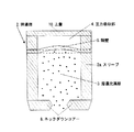
ロ)第2の実施例
図3は、他の実施例の押湯部2を示し、上記実施例と同様に、下型1bの製品キャビティ部6の上方で上型1a内に、断熱性材によるスリーブ2aを設けてある。8は押湯部2の下端部に設けたドーナツ状のネックダウンコアーを示し、ここでもシェル板製としてある。
B) Second Example FIG. 3 shows a feeder part 2 of another example, and in the same way as the above example, a heat insulating material is placed in the upper mold 1a above the product cavity 6 of the lower mold 1b. A sleeve 2a is provided. Denoted at 8 is a doughnut-shaped neck down core provided at the lower end of the hot water feeder 2, which is also made of a shell plate.
5は隔壁を示し、ここでも上記スリーブ2a内の下部が本来の押湯効果を発揮するための溶湯充満部3となり、上部が圧力増加を吸収する圧力吸収部4に形成されるように、スリーブ2a内の上部寄りに設置してある。該隔壁5はシェル板製としてあり、通常時は図3で点線で示す状態であるが、溶湯充満部3内が一定圧を越えた際に、同図で実線で示したように上方の圧力吸収部4側へ膨出して、溶湯充満部3内の容積が増加するように形成したものである。 Reference numeral 5 denotes a partition wall. In this case, the lower portion in the sleeve 2a is a molten metal filling portion 3 for exhibiting the original feeder effect, and the upper portion is formed in the pressure absorbing portion 4 for absorbing pressure increase. It is installed near the upper part in 2a. The partition wall 5 is made of a shell plate, and is normally in a state indicated by a dotted line in FIG. 3, but when the inside of the molten metal filling part 3 exceeds a certain pressure, an upward pressure as shown by a solid line in FIG. It swells to the absorption part 4 side, and is formed so that the volume in the molten metal filling part 3 may increase.
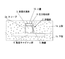
ハ)第3の実施例
図4は、さらに別の実施例の押湯部2を示し、下型1bの製品キャビティ部6の上方で上型1a内に、断熱性材によるスリーブ2aを設けてある。8は押湯部2の下端部に設けたドーナツ状のネックダウンコアーを示し、ここでもシェル板製としてある。
C) Third Example FIG. 4 shows a feeder part 2 of still another example, in which a sleeve 2a made of a heat insulating material is provided in the upper mold 1a above the product cavity 6 of the lower mold 1b. is there. Denoted at 8 is a doughnut-shaped neck down core provided at the lower end of the hot water feeder 2, which is also made of a shell plate.
5は隔壁を示し、上記スリーブ2a内が本来の押湯効果を発揮するための溶湯充満部3になるように、その上部に該隔壁5を設置してある。該隔壁5も溶湯充満部3内が一定圧を越えた際に、ここでは上方の圧力吸収部4側へ膨出可能又は開口可能なものとした。そして該隔壁5の上部に、熱で溶解し消失可能な材質として、ここでは発砲スチロール製で板状の部材17を設置してある。 Reference numeral 5 denotes a partition wall, and the partition wall 5 is installed on the upper portion of the sleeve 2a so that the inside of the sleeve 2a becomes a molten metal filling portion 3 for exhibiting the original hot-water feeder effect. When the inside of the molten metal filling part 3 exceeds a certain pressure, the partition wall 5 can be swelled or opened to the upper pressure absorbing part 4 side here. Here, a plate-like member 17 made of foamed polystyrene is installed on the upper part of the partition wall 5 as a material that can be dissolved and lost by heat.
これは、該発砲スチロール製部材17の体積分が圧力吸収部4となるようにしたものであって、溶湯充満部3内に注湯された溶湯の熱により、該部材17が消失して空所が形成されるから、そこが圧力吸収部4となる。この圧力吸収部4が増加圧力を受け入れることで、溶湯充満部3内が過大な圧力にならぬようにしたものである。 This is such that the volume of the foamed polystyrene member 17 becomes the pressure absorbing part 4, and the member 17 disappears due to the heat of the molten metal poured into the molten metal filling part 3. Since a place is formed, it becomes the pressure absorbing portion 4. This pressure absorption part 4 accepts the increased pressure so that the inside of the molten metal filling part 3 does not become an excessive pressure.
B.図5から図8は、本発明を特に生型自動造型機による造型に適するようにしたものを示す。
イ)第4の実施例
図5及び図6で示すもので、圧力吸収部4をスリーブ2a内に形成する点では上記第1及び第2の実施例と共通し、その変形例とも言えるものである。
B. FIGS. 5 to 8 show the present invention which is particularly suitable for molding by a green automatic molding machine.
B) Fourth embodiment As shown in FIGS. 5 and 6, the pressure absorbing portion 4 is formed in the sleeve 2a in common with the first and second embodiments, and can be said to be a modification thereof. is there.
上記第1及び第2の実施例で、予め形成しておいたスリーブ2aを、上型1a内に載置して鋳物砂を手込めで充填することにより、鋳型1の上型1aを形成するものであった。これに対してこの実施例では、上型1a内に生型自動造型機による造型にて、スリーブ挿入用の空所であるスリーブ用巾木18を予め形成しておく(図5参照)。その巾木18内に、内部に溶湯充満部3と圧力吸収部4と、溶湯充満部3内が一定圧を越えた際に上方の圧力吸収部4側へ膨出可能又は開口可能な隔壁5とを形成したスリーブ2aを挿入し、併せてネックダウンコアー8も挿入する(図6参照)。これにより、圧力吸収部4付きの押湯部2をもつ鋳型1(上型1a)が形成される。その他の点は、上記第1又は第2の実施例とほぼ同様である。 In the first and second embodiments, the sleeve 2a formed in advance is placed in the upper mold 1a and filled with foundry sand to form the upper mold 1a of the mold 1. It was a thing. On the other hand, in this embodiment, a sleeve base 18 which is a space for inserting a sleeve is formed in advance in the upper mold 1a by molding with a living automatic molding machine (see FIG. 5). In the baseboard 18, the molten metal filling portion 3, the pressure absorbing portion 4, and the partition wall 5 that can be expanded or opened to the upper pressure absorbing portion 4 side when the molten metal filling portion 3 exceeds a certain pressure. And the neck down core 8 is also inserted (see FIG. 6). Thereby, the casting_mold | template 1 (upper mold | type 1a) which has the feeder 2 with the pressure absorption part 4 is formed. Other points are almost the same as those in the first or second embodiment.
この実施例で、上型1aに予めスリーブ挿入用巾木18を造型しておき、抜型後にスリーブ2aを挿入することまでは、従来から行われている手法と同じであるが、本発明ではそのスリーブ2aに予め圧力吸収部4や隔壁5をも形成してあるものを用いており、そのスリーブ2aを巾木18内に挿入することで、内部に圧力吸収部4をもつ押湯部2付きの鋳型1を造型している点で、従来法とは異なるものである。 In this embodiment, until the sleeve insert base 18 is formed in advance in the upper die 1a and the sleeve 2a is inserted after the die removal, the method is the same as the conventional method. The sleeve 2a is preliminarily formed with the pressure absorbing portion 4 and the partition wall 5, and the sleeve 2a is inserted into the baseboard 18 so that the feeder 2 having the pressure absorbing portion 4 is provided inside. This is different from the conventional method in that the mold 1 is formed.
ロ)第5の実施例
図7及び図8で示すもので、圧力吸収部4をスリーブ2a外に形成する点では上記第3の実施例と共通し、その変形例とも言えるものである。
(B) Fifth Embodiment As shown in FIGS. 7 and 8, the pressure absorbing portion 4 is formed outside the sleeve 2a, and is common to the third embodiment, and can be said to be a modification thereof.
上記第3の実施例では、スリーブ2aの上部の隔壁5上に、熱で溶解し消失可能な発砲スチロール製の部材17を設置したものを用意しておき、それを上型1a内に載置して鋳物砂を手込めにより充填することで、鋳型1を造型するものであった。 In the third embodiment, a foamed polystyrene member 17 that can be melted and disappeared by heat is prepared on the partition wall 5 at the top of the sleeve 2a, and placed in the upper mold 1a. Then, the mold 1 was formed by manually filling the foundry sand.
これに対してこの実施例では、上型1a内に予め生型自動造型機による造型にて、上部が圧力吸収部4に対応する凹部即ち圧力吸収部用の凹部19となり、また下部がスリーブ2aを挿入可能な凹部20となるスリーブ用巾木18を形成しておく(図7参照)。その巾木18内に隔壁5を上部にもつスリーブ2aを挿入すると共に、ネックダウンコアー8を挿入する(図8参照)が、該隔壁5も溶湯充満部3内が一定圧を越えた際に上方の圧力吸収部4側へ膨出可能又は開口可能なものである。これにより、隔壁5上部でスリーブ2a外に圧力吸収部4が形成された押湯部2付きの鋳型1が造型される。その他の点は上記第4の実施例とほぼ同様である。 On the other hand, in this embodiment, the upper mold 1a is previously molded by a living automatic molding machine, and the upper part is a concave part corresponding to the pressure absorbing part 4, that is, the concave part 19 for the pressure absorbing part, and the lower part is the sleeve 2a. A sleeve skirting board 18 to be a recess 20 into which can be inserted is formed (see FIG. 7). A sleeve 2a having a partition wall 5 at the top is inserted into the baseboard 18 and a neck down core 8 is inserted (see FIG. 8). It can bulge or open to the upper pressure absorbing part 4 side. Thereby, the mold 1 with the feeder 2 in which the pressure absorbing portion 4 is formed outside the sleeve 2a at the upper part of the partition wall 5 is formed. The other points are almost the same as in the fourth embodiment.
この実施例でも、鋳型1に予めスリーブ挿入用巾木18を造型しておき、抜型後にスリーブ2aを挿入することは、従来から行われている手法と同じである。しかし本発明のスリーブ用巾木18は、上部が圧力吸収部用の凹部19となり、下部がスリーブ2aを挿入可能な凹部20となるスリーブ用巾木18を形成してある。その巾木18内に、上部に隔壁5をもつスリーブ2aを挿入して、隔壁5上方の凹部19が圧力吸収部4となるようにしている点で、従来法とは異なる。 Also in this embodiment, the sleeve insertion base 18 is formed in advance in the mold 1 and the sleeve 2a is inserted after the die removal is the same as the conventional method. However, the sleeve skirting board 18 of the present invention is formed with a sleeve skirting board 18 in which the upper part is a concave part 19 for a pressure absorbing part and the lower part is a concave part 20 into which the sleeve 2a can be inserted. A sleeve 2 a having a partition wall 5 at the top is inserted into the baseboard 18 so that the recess 19 above the partition wall 5 becomes the pressure absorbing portion 4, which is different from the conventional method.
なお、上記各実施例中で示した各部の材質・寸法等は例示であり、これに限定するものではない。上記実施例の内、スリーブ2aをスリーブ挿入用巾木18へ挿入する場合は、トップ押湯方式でもサイド押湯方式でも構わない。なお、サイド押湯方式の場合は、ネックダウンコアーを使用しないことが多い。 In addition, the material, dimension, etc. of each part shown in each said Example are illustrations, and are not limited to this. Of the above-described embodiments, when the sleeve 2a is inserted into the sleeve insertion skirting board 18, either a top feeder system or a side feeder system may be used. In the case of the side feeder type, a neck down core is often not used.
C.本発明の効果を確認する比較試験
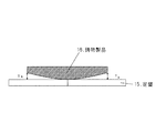
本発明として上記実施例の第1で示したものを用い、それを圧力吸収部をもたない従来のもの(以下の表2,3で比較例として記載したもの)と比較した。ここで用いた鋳鉄溶湯は、下記表1に示す2種類のものを、1370±20℃にて各々5機の鋳型に鋳込み、その後十分に冷却した後に各鋳物製品16の上型面と下型面に均等にショットブラスト処理を行った。これら鋳物製品16を定盤15に載置して検品を行ったところ、鋳物製品16の下型面中央付近で厚いなだらかな凸状の変形があることを確認した(図5参照)。
C. Comparative test for confirming the effect of the present invention The present invention uses the one shown in the first of the above-mentioned embodiments, and it is a conventional one having no pressure absorbing portion (described as a comparative example in Tables 2 and 3 below) )). The cast iron melts used here were cast in two types as shown in Table 1 below into molds of 5 machines each at 1370 ± 20 ° C., and after cooling sufficiently, the upper mold surface and lower mold of each cast product 16 Shot blasting was performed evenly on the surface. When these cast products 16 were placed on the surface plate 15 and inspected, it was confirmed that there was a thick, gentle convex deformation near the center of the lower mold surface of the cast product 16 (see FIG. 5).
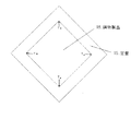
そこで、図9及び図10で示す如く各鋳物製品16について、Ta ,Tb ,Tc ,Td
で示す4か所でシックネスゲージにて測定し、その合計値(Ta 〜 d )を求めた。その価結果を下記表2及び表3で示すが、前者は溶湯の材質がFC−200の場合の結果で、後者はFCD−450の場合の結果である。
Therefore, as shown in FIGS. 9 and 10, for each casting product 16, Ta, Tb, Tc, Td.
The total values (Ta to d) were obtained by measuring with four thickness gauges. The valence results are shown in Tables 2 and 3 below. The former is the result when the melt material is FC-200, and the latter is the result when FCD-450 is used.
上記の結果、本発明の実施例の鋳型を用いて鋳造した製品には、各表の上段で示す如く殆ど変形が認められなかったが、本発明を用いない鋳型によるもの(比較例)では、各表の下段で示すように、鋳物製品16の下型面に変形が認められた。この変形は「型張り」によりもたらされた寸法不良である。 As a result of the above, almost no deformation was observed in the products cast using the molds of the examples of the present invention, as shown in the upper part of each table. As shown in the lower part of each table, deformation was observed on the lower mold surface of the cast product 16. This deformation is a dimensional defect brought about by “molding”.
また上記本発明の押湯部2をもつ実施例の鋳型1で、鋳造後の押湯部2内で隔壁5が上方に膨らんで破れ、開口7が形成されていることが確認できた。これは、溶湯による圧力増加分を圧力吸収部4へ逃がし、吸収したことを意味しており、これにより良好な鋳物製品16が鋳造されることが実証された。 Further, in the mold 1 of the embodiment having the feeder part 2 of the present invention, it was confirmed that the partition wall 5 swelled upward and was broken in the feeder part 2 after casting, and the opening 7 was formed. This means that the pressure increase due to the molten metal was released to the pressure absorbing portion 4 and absorbed, and it was demonstrated that a good casting product 16 was cast.
本発明は、密閉型の埋込み型押湯式を用いる鋳鉄鋳造において、発生する鋳型の軟弱な部分の変形防止、鋳物製品16の寸法不良の発生防止、「収縮巣」の発生も押さえて、良好な鋳物製品16を製造しようとする場合に、きわめて有効に利用することができる。 The present invention is good in cast iron casting using a sealed embedded feeder type, preventing deformation of a soft portion of the mold generated, preventing occurrence of defective dimensions of the cast product 16, and suppressing occurrence of “shrinkage nest”. This can be used very effectively when trying to manufacture a simple casting product 16.
1−鋳型
1a−上型
1b−下型
2−押湯部
2a−スリーブ
3−溶湯充満部
4−圧力吸収部
5−隔壁
6−製品キャビティ部
7−開口
8−ネックダウンコアー
9−ノッチ
10−上蓋
11−湯道
12−湯口
13−ガス抜き孔
14−揚り部
15−定盤
16−鋳物製品
17−発砲スチロール
18−スリーブ用巾木
19−凹部
20−凹部
1-mold 1a-upper mold 1b-lower mold 2 feeder part 2a-sleeve 3 molten metal filling part 4-pressure absorbing part 5-partition 6-product cavity part 7-opening 8-neck down core 9-notch 10- Top lid 11-Runway 12-Spout 13-Gas vent 14-Lifting part 15-Surface plate 16-Cast product 17-Styrofoam 18-Skirting sleeve 19-Recess 20-Recess
Claims (14)
製品キャビティ部6と連通する押湯部2を、本来の押湯効果を発揮するための溶湯充満部3と、その外部にあって、溶湯凝固時に発生する増加圧力吸収用の圧力吸収部4とで構成すると共に、
溶湯充満部3と圧力吸収部4間に、溶湯充満部3内が一定圧を越えた際にその増加圧力で圧力吸収部4側へ膨出可能な隔壁5を設けておき、
溶湯充満部3内へ鋳鉄溶湯を注湯して、その凝固時に溶湯充満部3内に発生する溶湯の増加圧力を圧力吸収部4へ逃がし、
これにより、製品キャビティ部6に過度の圧力が加わらぬようにして鋳造することを特徴とする、鋳鉄鋳造方法。 In a cast iron casting method using a mold 1 having an embedded feeder 2,
The hot water portion 2 communicating with the product cavity portion 6 includes a molten metal filling portion 3 for demonstrating the original hot metal effect, and a pressure absorbing portion 4 outside the molten metal filling portion 3 for absorbing increased pressure generated when the molten metal is solidified. And consisting of
A partition wall 5 is provided between the molten metal filling portion 3 and the pressure absorbing portion 4 and can bulge toward the pressure absorbing portion 4 with the increased pressure when the inside of the molten metal filling portion 3 exceeds a certain pressure,
The molten cast iron is poured into the molten metal filling portion 3, and the increased pressure of the molten metal generated in the molten metal filling portion 3 at the time of solidification is released to the pressure absorbing portion 4.
Thereby, casting is performed such that excessive pressure is not applied to the product cavity portion 6, and a cast iron casting method is characterized.
製品キャビティ部6と連通する押湯部2を、本来の押湯効果を発揮するための溶湯充満部3と、その外部にあって、溶湯凝固時に発生する増加圧力吸収用の圧力吸収部4とで構成すると共に、
溶湯充満部3と圧力吸収部4間に、溶湯充満部3内が一定圧を越えた際にその増加圧力で圧力吸収部4側へ割れて開口可能な隔壁5を設けておき、
溶湯充満部3内へ鋳鉄溶湯を注湯して、その凝固時に溶湯充満部3内に発生する溶湯の増加圧力を圧力吸収部4へ逃がし、
これにより、製品キャビティ部6に過度の圧力が加わらぬようにして鋳造することを特徴とする、鋳鉄鋳造方法。 In a cast iron casting method using a mold 1 having an embedded feeder 2,
The hot water portion 2 communicating with the product cavity portion 6 includes a molten metal filling portion 3 for demonstrating the original hot metal effect, and a pressure absorbing portion 4 outside the molten metal filling portion 3 for absorbing increased pressure generated when the molten metal is solidified. And consisting of
A partition wall 5 is provided between the molten metal filling portion 3 and the pressure absorbing portion 4 so that when the inside of the molten metal filling portion 3 exceeds a predetermined pressure, the partition wall 5 can be opened by being cracked to the pressure absorbing portion 4 side with the increased pressure.
The molten cast iron is poured into the molten metal filling portion 3, and the increased pressure of the molten metal generated in the molten metal filling portion 3 at the time of solidification is released to the pressure absorbing portion 4.
Thereby, casting is performed such that excessive pressure is not applied to the product cavity portion 6, and a cast iron casting method is characterized.
鋳鉄溶湯を充満させる製品キャビティ部6に連通する如く設ける該押湯部2として、
本来の押湯効果を発揮するための溶湯充満部3と、その外部に、鋳鉄溶湯の凝固時の溶湯の増加圧力吸収用の圧力吸収部4を設けると共に、
溶湯充満部3と圧力吸収部4との間に、溶湯充満部3内が一定圧を越えた際にその増加圧力で圧力吸収部4側へ割れて開口可能な隔壁5を設けたことを特徴とする、鋳鉄鋳造用の押湯部。 In the buried type hot-water part 2,
As the hot water supply part 2 provided so as to communicate with the product cavity part 6 filled with cast iron melt,
While providing a molten metal filling portion 3 for demonstrating the original hot metal effect, and a pressure absorbing portion 4 for absorbing the increased pressure of the molten metal at the time of solidification of the cast iron melt,
A partition wall 5 is provided between the molten metal filling portion 3 and the pressure absorbing portion 4 that can be opened to crack the pressure absorbing portion 4 with the increased pressure when the molten metal filling portion 3 exceeds a certain pressure. A feeder for casting cast iron.
鋳鉄溶湯を充満させる製品キャビティ部6に連通する如く設ける該押湯部2として、
本来の押湯効果を発揮するための溶湯充満部3と、その外部に、鋳鉄溶湯の凝固時の溶湯の増加圧力吸収用の圧力吸収部4を設けると共に、
溶湯充満部3と圧力吸収部4との間に、溶湯充満部3内が一定圧を越えた際にその増加圧力で圧力吸収部4側へ膨出可能な隔壁5を設けたことを特徴とする、鋳鉄鋳造用の押湯部。 It is an embedded type feeder section 2,
As the hot water supply part 2 provided so as to communicate with the product cavity part 6 filled with cast iron melt,
While providing a molten metal filling portion 3 for demonstrating the original hot metal effect, and a pressure absorbing portion 4 for absorbing the increased pressure of the molten metal at the time of solidification of the cast iron melt,
A partition wall 5 is provided between the molten metal filling portion 3 and the pressure absorbing portion 4 that can bulge toward the pressure absorbing portion 4 with the increased pressure when the inside of the molten metal filling portion 3 exceeds a certain pressure. A feeder for casting cast iron.
鋳鉄溶湯を充満する製品キャビティ部6に連通する如く設ける該押湯部2を、
本来の押湯効果を発揮するための溶湯充満部3と、その外部に、鋳鉄溶湯の凝固時の溶湯の増加圧力吸収用の圧力吸収部4を設けるものとすると共に、
溶湯充満部3と圧力吸収部4との間に、溶湯充満部3内が一定圧を越えた際にその増加圧力で圧力吸収部4側へ割れて開口可能な隔壁5を設け、
かつ、該隔壁5の上部に、熱で消失可能な材質製の部材17を設置して、その消失で形成される空所が上記圧力吸収部4となるようにしたことを特徴とする、鋳鉄鋳造用の押湯部。 It is an embedded type feeder section 2,
The feeder part 2 provided so as to communicate with the product cavity part 6 filled with molten cast iron,
The molten metal filling portion 3 for demonstrating the original hot metal effect and the pressure absorbing portion 4 for absorbing the increased pressure of the molten metal at the time of solidification of the cast iron molten metal are provided outside thereof,
Between the molten metal filling part 3 and the pressure absorption part 4, when the inside of the molten metal filling part 3 exceeds a certain pressure, a partition wall 5 is provided which can be opened to crack to the pressure absorption part 4 side with the increased pressure.
The cast iron is characterized in that a member 17 made of a material that can be lost by heat is installed on the upper part of the partition wall 5 so that a space formed by the disappearance becomes the pressure absorbing portion 4. A feeder for casting.
鋳鉄溶湯を充満する製品キャビティ部6に連通する如く設ける該押湯部2を、
本来の押湯効果を発揮するための溶湯充満部3と、その外部に、鋳鉄溶湯の凝固時の溶湯の増加圧力吸収用の圧力吸収部4を設けるものとすると共に、
溶湯充満部3と圧力吸収部4との間に、溶湯充満部3内が一定圧を越えた際にその増加圧力で圧力吸収部4側へ膨出可能な隔壁5を設け、
かつ、該隔壁5の上部に、熱で消失可能な材質製の部材17を設置して、その消失で形成される空所が上記圧力吸収部4となるようにしたことを特徴とする、鋳鉄鋳造用の押湯部。 It is an embedded type feeder section 2,
The feeder part 2 provided so as to communicate with the product cavity part 6 filled with molten cast iron,
The molten metal filling portion 3 for demonstrating the original hot metal effect and the pressure absorbing portion 4 for absorbing the increased pressure of the molten metal at the time of solidification of the cast iron molten metal are provided outside thereof,
A partition wall 5 is provided between the molten metal filling portion 3 and the pressure absorbing portion 4 that can bulge toward the pressure absorbing portion 4 with the increased pressure when the inside of the molten metal filling portion 3 exceeds a certain pressure,
The cast iron is characterized in that a member 17 made of a material that can be lost by heat is installed on the upper part of the partition wall 5 so that a space formed by the disappearance becomes the pressure absorbing portion 4. A feeder for casting.
鋳鉄溶湯を充満する製品キャビティ部6に連通する如く設ける該押湯部2を、
本来の押湯効果を発揮するための溶湯充満部3と、該溶湯充満部3内が一定圧を越えた際にその増加圧力で割れて開口可能な隔壁5とを設けると共に、
鋳型1内で上記隔壁5の外方に当たる箇所に圧力吸収部用の凹部19を予め形成したものとし、
鋳鉄溶湯の凝固時の溶湯の増加圧力を、隔壁5を経て上記凹部19による圧力吸収部4へ逃がし得るようにしたことを特徴とする、鋳鉄鋳造用の押湯部。 It is an embedded type feeder section 2,
The feeder part 2 provided so as to communicate with the product cavity part 6 filled with molten cast iron,
While providing the molten metal filling part 3 for demonstrating the original feeder effect, and the partition wall 5 that can be broken and opened by the increased pressure when the molten metal filling part 3 exceeds a certain pressure,
It is assumed that a concave portion 19 for a pressure absorbing portion is formed in advance at a location that contacts the outside of the partition wall 5 in the mold 1.
A feeder for casting cast iron, characterized in that the increased pressure of the molten metal at the time of solidification of the cast iron can be released through the partition wall 5 to the pressure absorbing part 4 by the recess 19.
鋳鉄溶湯を充満する製品キャビティ部6に連通する如く設ける該押湯部2を、
本来の押湯効果を発揮するための溶湯充満部3と、該溶湯充満部3内が一定圧を越えた際にその増加圧力で後記凹部19側へ膨出可能な隔壁5とを設けると共に、
鋳型1内で上記隔壁5の外方に当たる箇所に圧力吸収部用の凹部19を予め形成したものとし、
鋳鉄溶湯の凝固時の溶湯の増加圧力を、隔壁5を経て上記凹部19による圧力吸収部4へ逃がし得るようにしたことを特徴とする、鋳鉄鋳造用の押湯部。 It is an embedded type feeder section 2,
The feeder part 2 provided so as to communicate with the product cavity part 6 filled with molten cast iron,
While providing the molten metal filling part 3 for demonstrating the original feeder effect, and the partition wall 5 that can bulge to the concave part 19 side described later with the increased pressure when the inside of the molten metal filling part 3 exceeds a certain pressure,
It is assumed that a concave portion 19 for a pressure absorbing portion is formed in advance at a location that contacts the outside of the partition wall 5 in the mold 1.
A feeder for casting cast iron, characterized in that the increased pressure of the molten metal at the time of solidification of the cast iron can be released through the partition wall 5 to the pressure absorbing part 4 by the recess 19.
鋳鉄溶湯を充満させる製品キャビティ部6に連通する如く押湯部2を設け、
該押湯部2を、上記請求項3,4,5,6,7又は8に記載のものにしたことを特徴とする、鋳鉄鋳造用の鋳型。 A mold that uses an embedded type hot-water feeder 2,
The hot water supply part 2 is provided so as to communicate with the product cavity part 6 filled with the molten cast iron,
A cast iron casting mold characterized in that the feeder part 2 is the one described in claim 3, 4, 5, 6, 7 or 8.
予め形成しておいた上記請求項3,4,5又は6に記載した押湯部2を、鋳型内に載置して鋳物砂を手込めで充填することにより、上型1aを造型するようにしたことを特徴とする、鋳鉄鋳造用の鋳型の造型方法。 A mold making method for cast iron casting,
The upper die 1a is formed by placing the feeder part 2 described in claim 3, 4, 5 or 6 previously formed in a mold and filling it with casting sand by hand. A method for forming a mold for casting cast iron, characterized in that
生型自動造型機による造型にて予め鋳型1内に、スリーブ挿入用の空所であるスリーブ用巾木18を形成しておき、
そのスリーブ用巾木18内に、予め溶湯充満部3と、圧力吸収部4と、その間に、溶湯充満部3内が一定圧を越えた際にその増加圧力で圧力吸収部4側へ膨出可能な隔壁5とを設けたスリーブ2aを挿入することにより、
圧力吸収部4付き押湯部2をもつ上型1aを造型することを特徴とする、鋳鉄鋳造用の鋳型の造型方法。 A mold making method for cast iron casting,
A sleeve base 18 which is a space for inserting a sleeve is formed in the mold 1 in advance by molding with a raw automatic molding machine,
In the sleeve skirting board 18, the molten metal filling portion 3 and the pressure absorbing portion 4 are swelled to the pressure absorbing portion 4 side with the increased pressure when the inside of the molten metal filling portion 3 exceeds a certain pressure. By inserting a sleeve 2a provided with a possible partition wall 5,
A casting mold casting method for casting a cast iron, characterized by molding an upper mold 1a having a feeder section 2 with a pressure absorbing section 4.
生型自動造型機による造型にて予め鋳型1内に、スリーブ挿入用の空所であるスリーブ用巾木18を形成しておき、
そのスリーブ用巾木18内に、予め溶湯充満部3と、圧力吸収部4と、その間に、溶湯充満部3内が一定圧を越えた際にその増加圧力で割れて開口可能な隔壁5とを設けたスリーブ2aを挿入することにより、
圧力吸収部4付き押湯部2をもつ上型1aを造型することを特徴とする、鋳鉄鋳造用の鋳型の造型方法。 A mold making method for cast iron casting,
A sleeve base 18 which is a space for inserting a sleeve is formed in the mold 1 in advance by molding with a raw automatic molding machine,
In the sleeve skirting board 18, the molten metal filling portion 3 and the pressure absorbing portion 4, and the partition wall 5 that can be opened by being cracked by the increased pressure when the inside of the molten metal filling portion 3 exceeds a certain pressure. By inserting the sleeve 2a provided with
A casting mold casting method for casting a cast iron, characterized by molding an upper mold 1a having a feeder section 2 with a pressure absorbing section 4.
生型自動造型機による造型にて予め鋳型1内に、上部に圧力吸収部用の凹部19と、下部にスリーブ2aを挿入可能な凹部20を有するスリーブ用巾木18を形成しておき、
溶湯充満部3内が一定圧を越えた際にその増加圧力で割れて開口可能な隔壁5を上部に形成したスリーブ2aを、そのスリーブ用巾木18内に挿入して、隔壁5上方の凹部19が圧力吸収部4になるようにすることにより、
圧力吸収部4付き押湯部2をもつ上型1aを造型することを特徴とする、鋳鉄鋳造用の鋳型の造型方法。 A mold making method for cast iron casting,
A sleeve base plate 18 having a concave portion 19 for pressure absorbing portion at the upper portion and a concave portion 20 into which the sleeve 2a can be inserted at the lower portion is formed in the mold 1 in advance by molding with a raw automatic molding machine,
When the molten metal filling part 3 exceeds a certain pressure, the sleeve 2a having the partition wall 5 that can be opened by cracking with the increased pressure is inserted into the sleeve base 18 and the recess above the partition wall 5 is inserted. By making 19 become the pressure absorption part 4,
A casting mold casting method for casting a cast iron, characterized by molding an upper mold 1a having a feeder section 2 with a pressure absorbing section 4.
生型自動造型機による造型にて予め鋳型1内に、上部に圧力吸収部用の凹部19と、下部にスリーブ2aを挿入可能な凹部20を有するスリーブ用巾木18を形成しておき、
溶湯充満部3内が一定圧を越えた際にその増加圧力で上記凹部19側へ膨出可能な隔壁5を上部に形成したスリーブ2aを、そのスリーブ用巾木18内に挿入して、隔壁5上方の凹部19が圧力吸収部4になるようにすることにより、
圧力吸収部4付き押湯部2をもつ上型1aを造型することを特徴とする、鋳鉄鋳造用の鋳型の造型方法。 A mold making method for cast iron casting,
A sleeve base plate 18 having a concave portion 19 for pressure absorbing portion at the upper portion and a concave portion 20 into which the sleeve 2a can be inserted at the lower portion is formed in the mold 1 in advance by molding with a raw automatic molding machine,
When the inside of the molten metal filling portion 3 exceeds a certain pressure, a sleeve 2a having a partition wall 5 formed on the upper portion thereof that can bulge toward the concave portion 19 with the increased pressure is inserted into the sleeve base plate 18, 5 By making the upper concave portion 19 become the pressure absorbing portion 4,
A casting mold casting method for casting a cast iron, characterized by molding an upper mold 1a having a feeder section 2 with a pressure absorbing section 4.
Priority Applications (1)
| Application Number | Priority Date | Filing Date | Title |
|---|---|---|---|
| JP2009101428A JP5352785B2 (en) | 2009-04-17 | 2009-04-17 | Cast iron casting method, feeder, mold and mold making method |
Applications Claiming Priority (1)
| Application Number | Priority Date | Filing Date | Title |
|---|---|---|---|
| JP2009101428A JP5352785B2 (en) | 2009-04-17 | 2009-04-17 | Cast iron casting method, feeder, mold and mold making method |
Publications (2)
| Publication Number | Publication Date |
|---|---|
| JP2010247211A JP2010247211A (en) | 2010-11-04 |
| JP5352785B2 true JP5352785B2 (en) | 2013-11-27 |
Family
ID=43310160
Family Applications (1)
| Application Number | Title | Priority Date | Filing Date |
|---|---|---|---|
| JP2009101428A Expired - Fee Related JP5352785B2 (en) | 2009-04-17 | 2009-04-17 | Cast iron casting method, feeder, mold and mold making method |
Country Status (1)
| Country | Link |
|---|---|
| JP (1) | JP5352785B2 (en) |
Families Citing this family (2)
| Publication number | Priority date | Publication date | Assignee | Title |
|---|---|---|---|---|
| JP2018058103A (en) * | 2016-10-07 | 2018-04-12 | 日立金属株式会社 | Gate riser formation body and method for producing casting using gate riser formation body |
| CN107695297A (en) * | 2017-09-27 | 2018-02-16 | 安徽应流集团霍山铸造有限公司 | Blind riser heating pressure-maintaining structure |
Family Cites Families (2)
| Publication number | Priority date | Publication date | Assignee | Title |
|---|---|---|---|---|
| DE10156571C1 (en) * | 2001-11-20 | 2003-01-16 | Gtp Schaefer Giestechnische Pr | Feeder, used for inserting into a casting mold for casting metals, comprises a hat-like cap enclosing the outer wall of a feeder body forming an insulating gap and fixed against the body |
| JP2010042438A (en) * | 2008-08-09 | 2010-02-25 | Ie Solution Kk | Riser and riser sleeve structure |
-
2009
- 2009-04-17 JP JP2009101428A patent/JP5352785B2/en not_active Expired - Fee Related
Also Published As
| Publication number | Publication date |
|---|---|
| JP2010247211A (en) | 2010-11-04 |
Similar Documents
| Publication | Publication Date | Title |
|---|---|---|
| RU2635596C2 (en) | Method for manufacturing hollow metal workpiece by casting | |
| US9308578B2 (en) | Subsurface chills to improve railcar knuckle formation | |
| CN106475523B (en) | Feeding system | |
| JP2009274098A (en) | Sand mold for low-pressure casting and low-pressure casting apparatus utilizing the same | |
| CN105414487A (en) | Large loam core fixing method | |
| CN104827000A (en) | Gear ring casting method | |
| CN103878324B (en) | A kind of cylinder cap casting die and casting method | |
| JP5352785B2 (en) | Cast iron casting method, feeder, mold and mold making method | |
| RU2013158941A (en) | METHOD FOR CASTING PUSHERS OF RAILWAY CARS | |
| MX2008011212A (en) | Composite foundry core and casting method using said core. | |
| CN106424577A (en) | Sand core device and method for preventing hot cracks during steel casting iron mold sand covering casting production | |
| JP5352786B2 (en) | Cast iron casting method, feeder, mold and mold making method | |
| CN202984578U (en) | Cylinder cover casting die | |
| CN103273008A (en) | Cold box combined core iron shot filling and pouring production technology of automobile engine casting | |
| JP2018058103A (en) | Gate riser formation body and method for producing casting using gate riser formation body | |
| JP6826751B2 (en) | A presser foot forming body and a method for manufacturing a casting using the presser foot forming body. | |
| CN205732835U (en) | Venting plug | |
| CN101733387B (en) | Low pressure casting method of aluminium alloy lost foam | |
| US8276644B2 (en) | Mold and casting method using the mold and design method of the mold | |
| CN104148585A (en) | Casting method for nodular cast iron crankshaft used for internal combustion locomotive | |
| CN204770614U (en) | Nodular cast iron casting structure with fin | |
| CN204817930U (en) | Car cylinder body core | |
| JP4029626B2 (en) | Mold structure | |
| CN113042681B (en) | Mixed foam model manufacturing process for preventing important surface residues of iron castings | |
| CN105921695A (en) | Exhaust plug and casting process |
Legal Events
| Date | Code | Title | Description |
|---|---|---|---|
| A621 | Written request for application examination |
Free format text: JAPANESE INTERMEDIATE CODE: A621 Effective date: 20120406 |
|
| A977 | Report on retrieval |
Free format text: JAPANESE INTERMEDIATE CODE: A971007 Effective date: 20130207 |
|
| TRDD | Decision of grant or rejection written | ||
| A01 | Written decision to grant a patent or to grant a registration (utility model) |
Free format text: JAPANESE INTERMEDIATE CODE: A01 Effective date: 20130709 |
|
| A61 | First payment of annual fees (during grant procedure) |
Free format text: JAPANESE INTERMEDIATE CODE: A61 Effective date: 20130725 |
|
| R150 | Certificate of patent or registration of utility model |
Ref document number: 5352785 Country of ref document: JP Free format text: JAPANESE INTERMEDIATE CODE: R150 Free format text: JAPANESE INTERMEDIATE CODE: R150 |
|
| R250 | Receipt of annual fees |
Free format text: JAPANESE INTERMEDIATE CODE: R250 |
|
| R250 | Receipt of annual fees |
Free format text: JAPANESE INTERMEDIATE CODE: R250 |
|
| R250 | Receipt of annual fees |
Free format text: JAPANESE INTERMEDIATE CODE: R250 |
|
| R250 | Receipt of annual fees |
Free format text: JAPANESE INTERMEDIATE CODE: R250 |
|
| R250 | Receipt of annual fees |
Free format text: JAPANESE INTERMEDIATE CODE: R250 |
|
| LAPS | Cancellation because of no payment of annual fees |