JP5351663B2 - Imaging apparatus and control method thereof - Google Patents
Imaging apparatus and control method thereof Download PDFInfo
- Publication number
- JP5351663B2 JP5351663B2 JP2009201093A JP2009201093A JP5351663B2 JP 5351663 B2 JP5351663 B2 JP 5351663B2 JP 2009201093 A JP2009201093 A JP 2009201093A JP 2009201093 A JP2009201093 A JP 2009201093A JP 5351663 B2 JP5351663 B2 JP 5351663B2
- Authority
- JP
- Japan
- Prior art keywords
- imaging
- correction amount
- image data
- luminance
- dynamic range
- Prior art date
- Legal status (The legal status is an assumption and is not a legal conclusion. Google has not performed a legal analysis and makes no representation as to the accuracy of the status listed.)
- Active
Links
Images

Landscapes
- Studio Devices (AREA)
Description
本発明は、撮像装置およびその制御方法に関する。 The present invention relates to an imaging apparatus and a control method thereof.
従来、CCDイメージセンサやCMOSイメージセンサなどの撮像素子を用いたデジタルカメラやデジタルビデオが広く用いられている。しかし、これらの撮像素子は銀塩フィルムと比較してダイナミックスレンジ(ラチチュード)が狭い。そのため、高コントラストのシーンを撮像すると、低輝度部分の階調性悪化(黒つぶれ)や高輝度部分の階調性悪化(白とび)が発生しやすかった。 Conventionally, digital cameras and digital videos using image sensors such as CCD image sensors and CMOS image sensors have been widely used. However, these image sensors have a narrow dynamic range (latitude) compared to silver salt films. For this reason, when a high-contrast scene is imaged, gradation deterioration (blackout) in a low-luminance portion and gradation deterioration (whiteout) in a high-luminance portion are likely to occur.
このような問題に対し、自動的にダイナミックスレンジをコントロール可能なシステムが提案されている。
例えば特許文献1では、撮像された画像から、主要被写体が逆光又はハイコントラストであると検出された場合には、画像のヒストグラムから黒色飽和点及び白色飽和点を特定し、主要被写体の明るさが適正となるように階調補正を行うことが提案されている。
In response to such a problem, a system capable of automatically controlling the dynamic range has been proposed.
For example, in
また、特許文献2では、高感度の受光素子と低感度の受光素子を配置した撮像素子を用い、同一シーンを異なる感度の受光素子で撮像してダイナミックレンジの異なる2種類の画像を取得し、それらをシーン解析結果に応じて合成することが提案されている。 Moreover, in patent document 2, using the imaging device which has arrange | positioned the high sensitivity light receiving element and the low sensitivity light receiving element, the same scene is imaged with the light receiving element of different sensitivity, and two types of images with different dynamic ranges are acquired, It has been proposed to synthesize them according to the scene analysis results.
さらに、撮像感度の設定範囲を1段高感度よりにシフト(ISO 100-3200をISO 200-6400にシフト)することで、ハイライト部分の階調表現性を向上させる高輝度側階調優先モードを有する撮像装置も知られている(非特許文献1)。 In addition, by shifting the setting range of the imaging sensitivity from one level higher sensitivity (shifting ISO 100-3200 to ISO 200-6400), the high brightness side tone priority mode that improves the tone expression of highlights There is also known an imaging device having a non-patent document 1).
しかし、特許文献1の方法では、コントラスト感を高めるための効果はあるものの、センサーが飽和するポイントは変わらないため、ダイナミックレンジを拡げる効果は得られない。
However, in the method of
また、特許文献2の方法では、ダイナミックレンジを拡げる効果は得られるが、感度の異なる受光素子を配置した特別な撮像素子を用いる必要があるため、コストがかかるという問題点があった。 Further, although the method of Patent Document 2 can obtain the effect of expanding the dynamic range, there is a problem that it is expensive because it is necessary to use a special imaging device in which light receiving elements having different sensitivities are arranged.
また、非特許文献1に記載される撮像装置においては、高輝度側の階調性を向上させるべきか否かを、シーンに応じてユーザが都度判断しなければならない。そのため、高輝度側階調優先モードを有効に利用できるかどうかは、ユーザが正しく判断し、かつ正しくモードの設定を行った場合に限られる。
Further, in the imaging device described in
一方、被写体のダイナミックレンジが拡大されても、出力装置のダイナミックレンジは変わらないため、撮像画像のコントラストが低下するといった弊害も発生しうる。また、最適なダイナミックレンジ拡大量もシーンにより異なるため、シーンを解析して最適なダイナミックレンジ拡大量を決定する必要がある。 On the other hand, even if the dynamic range of the subject is expanded, the dynamic range of the output device does not change. Further, since the optimum dynamic range expansion amount varies depending on the scene, it is necessary to determine the optimum dynamic range expansion amount by analyzing the scene.
たとえば、近年では、画面内の顔を検出し、顔の明るさが適正となるように自動露出制御する顔AE機能を搭載する撮像装置が一般的になっている。このような顔AE機能を搭載している撮像装置で、人物を逆光で撮像する場合には、顔の明るさが最適になるように露出制御すると、背景が露出オーバーとなり白とび領域が多くなる場合がある。このような状況での撮像では、全体のコントラストよりも、主被写体である人物の顔の明るさが適正で、かつ背景の白とびをなるべく抑えることが重視される。そのため、ダイナミックレンジの拡大量を大きく設定したほうが好ましい画像が得られる。 For example, in recent years, imaging apparatuses equipped with a face AE function that detects a face in a screen and automatically controls exposure so that the brightness of the face is appropriate have become common. When taking an image of a person in the backlight with an imaging device equipped with such a face AE function, if the exposure is controlled so that the brightness of the face is optimal, the background will be overexposed and the overexposed area will increase. There is a case. In imaging in such a situation, it is more important than the overall contrast that the brightness of the face of the person who is the main subject is appropriate and the background overexposure is suppressed as much as possible. For this reason, it is possible to obtain an image with a larger dynamic range expansion amount.
逆に、砂浜や雪山のような白い被写体が含まれるようなシーンにおいては、白とびを抑えるようにダイナミックレンジの拡大量を大きくすると、コントラストが低く、好ましくない画像が得られてしまう場合がある。 Conversely, in scenes that include white subjects such as sandy beaches and snowy mountains, increasing the dynamic range expansion amount to suppress overexposure may result in low contrast and unfavorable images. .
つまり、ダイナミックレンジの制御は、被写体や撮像シーンに応じてきめ細かに、かつ自動で行うことが望まれるが、従来はこのようなダイナミックレンジの制御は実現できていなかった。 In other words, it is desired that the dynamic range control be performed finely and automatically in accordance with the subject and the imaging scene, but conventionally such dynamic range control has not been realized.
本発明はこのような従来技術の問題点に鑑みなされたものであり、被写体や撮像シーンに応じてきめ細かに、かつ自動でダイナミックレンジの制御を行うことのできる撮像装置及びその制御方法を提供する。 The present invention has been made in view of the above-described problems of the prior art, and provides an imaging apparatus capable of finely controlling a dynamic range automatically according to a subject and an imaging scene, and a control method thereof. .
上述の目的を達成するため、本発明の第1の見地による撮像装置は、撮像を行い画像データを取得する撮像手段と、撮像手段により取得された画像データの輝度のヒストグラムに基づいて第1の補正量を算出する第1の算出手段と、撮像手段により取得された画像データの領域間の輝度差に基づいて第2の補正量を算出する第2の算出手段と、第1の補正量及び第2の補正量を比較した結果に基づいて、撮像感度及び露出の少なくとも一方の低減量を決定する決定手段と、決定手段により決定された低減量に基づいて撮像手段により撮像を行い、取得された画像データに対して低減量を補う信号処理を適用する補正手段とを有することを特徴とする。 In order to achieve the above-described object, an imaging apparatus according to a first aspect of the present invention includes an imaging unit that performs imaging and acquires image data, and a first histogram based on a luminance histogram of the image data acquired by the imaging unit . A first calculation unit that calculates a correction amount ; a second calculation unit that calculates a second correction amount based on a luminance difference between regions of image data acquired by the imaging unit ; a first correction amount; based on the result of comparing the second correction amount, it captures an image determination means for determining at least one of the reduction amount of the imaging sensitivity and the exposure by the imaging means on the basis of the reduction amount determined by the decision means, obtaining And correction means for applying signal processing for compensating the reduction amount to the image data .
このような構成により、本発明によれば、被写体や撮像シーンに応じてきめ細かに、かつ自動でダイナミックレンジの制御を行うことができる。 With such a configuration, according to the present invention, the dynamic range can be controlled finely and automatically according to the subject and the imaging scene.
(第1の実施形態)
以下、添付図面を参照して、本発明を例示的な実施形態に基づき詳細に説明する。
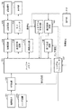
図1は、本発明の実施形態に係る撮像装置の構成例を示すブロック図である。本実施形態の撮像装置は、撮像素子を用いて画像を撮像する機能を有する任意の装置を包含する。このような装置は、デジタルスチルカメラおよびデジタルビデオカメラはもとより、カメラを内蔵または接続した携帯電話、PDA、パーソナルコンピュータなどを含む。
(First embodiment)
Hereinafter, the present invention will be described in detail based on exemplary embodiments with reference to the accompanying drawings.
FIG. 1 is a block diagram illustrating a configuration example of an imaging apparatus according to an embodiment of the present invention. The imaging apparatus according to the present embodiment includes any apparatus having a function of capturing an image using an imaging element. Such devices include not only digital still cameras and digital video cameras, but also mobile phones, PDAs, personal computers, etc. that have built-in or connected cameras.
図1において、操作部112は、ボタン、スイッチなどを含み、ユーザが撮像装置に指示を与えたり、設定を行ったりするために用いられる。シャッターボタンも操作部112に含まれ、本実施形態ではシャッターボタンの半押し状態と全押し状態とを検出可能であるものとする。
In FIG. 1, the
システムコントローラ107は、シャッターボタンの半押し状態を撮像準備開始指示、全押し状態を撮像開始指示として認識する。システムコントローラ107は、例えば、CPU、ROM、RAMなどを含み、ROMに記憶されたプログラムをRAMを用いてCPUが実行することにより、撮像装置の動作全般を制御する。
The
レンズ装置200は、フォーカスレンズを含むレンズ群と、フォーカスレンズを駆動する駆動装置と、絞りと、メカニカルシャッターとを有し、システムコントローラ107の制御に基づいて動作する。
The
撮像素子101はCCDイメージセンサ、CMOSイメージセンサなどの光電変換素子である。アナログフロントエンド(AFE)回路150は、撮像素子101から出力されるアナログ画像信号に対してゲイン調整やA/D変換などを行い、デジタル画像信号として出力する。
The
バッファメモリ103は、AFE回路150が出力するデジタル画像信号を一時的に記憶する。
圧縮・伸長回路104は、撮像画像データを記録用の画像ファイル(例えばJPEGファイル)の形式に符号化したり、記録媒体106から読み出された画像ファイルの復号化を行ったりする。
The
The compression /
記録装置105は、内蔵メモリや、着脱可能なメモリカードのような記録媒体106に対し、システムコントローラ107の制御に従ってデータの読み書きを行う。
表示制御回路108は、システムコントローラ107の制御に従い、LCDなどの表示デバイスを有する表示部110への表示動作を制御する。
D/Aコンバータ109は、表示制御回路108が出力する表示用のデジタル画像信号を表示部110が表示可能なアナログ画像信号に変換する。
The
The
The D /
表示部110は、撮像した画像の表示はもとより、ユーザが撮像装置に対して各種の設定や指示を行うためのGUI画面や、撮像装置に関する各種情報などの表示を行う。また、連続的に撮像した画像を表示部110に逐次表示することにより、表示部110を電子ビューファインダ(EVF)として機能させることができる。この、表示部110をEVFとして機能させるための逐次撮像・表示動作は、スルー表示、ライブビュー表示とも呼ばれる。
The
顔検出回路120は、バッファメモリ103に記憶された、YUV形式またはRAW形式の画像データに対して顔検出処理を行い、画像中の顔領域の大きさ、位置を含む顔検出結果をヒストグラム作成回路130に出力する。
The
顔検出回路120が用いる顔検出方法に特に制限はなく、任意かつ公知の方法を適用することができる。公知の顔検出技術としては、ニューラルネットワークなどを利用した学習に基づく手法、テンプレートマッチングを用いて目、鼻、口等の形状に特徴のある部位を画像から探し出し、類似度が高ければ顔とみなす手法などがある。また、他にも、肌の色や目の形といった画像特徴量を検出し、統計的解析を用いた手法等、多数提案されている。これらの手法を複数組み合わせ、顔検出の精度を向上させることもできる。具体的な例としては特開2002−251380号公報に記載のウェーブレット変換と画像特徴量を利用して顔検出する方法などが挙げられる。本実施形態の顔検出回路120は、一対の目(両目)、鼻、口を検出し、これらの相対位置より人物の顔領域を決定する手法により顔検出処理を行うものとする。
The face detection method used by the
ヒストグラム作成回路130は、顔領域の検出結果を顔検出回路120から取得し、バッファメモリ103に記憶された画像データのうち、顔領域に含まれる画素の輝度のヒストグラムを作成する。ヒストグラム作成回路130はまた、画像を複数に分割した部分領域毎に、含まれる画素の輝度のヒストグラムも作成することが可能である。作成したヒストグラムはバッファメモリ103に格納する。本実施形態では、画面を縦横4分割した16の領域に分割し、領域毎のヒストグラムを作成する。
The
信号処理回路140は、システムコントローラ107によって設定される信号処理パラメータ(ホワイトバランス補正係数やガンマパラメータなど)に従って、バッファメモリ103に格納されている画像データに対して信号処理を適用する。そして、信号処理回路140は、YUV形式の画像データを生成し、再びバッファメモリ103に格納する。
The
露出制御回路160はバッファメモリ103に記憶された画像データ、顔検出回路120による顔検出結果、並びに露出制御に関する設定値(シーンモードや、顔優先モード、絞り又はシャッタースピード優先モードなど)に基づいて自動露出制御を行う。露出制御回路160は、自動露出制御により決定した露出パラメータ(絞り、シャッタースピード、感度)をシステムコントローラ107に通知する。
The
次に、上述の構成を有する撮像装置における、撮像時の動作について説明する。
撮像モードで動作しており、撮像準備指示や撮像開始指示が入力されていないスタンバイ時において、本実施形態の撮像装置は、表示部110をEVFとして機能させている。すなわち、システムコントローラ107は、所定のレート(例えば30フレーム/秒)で連続的に撮像し、撮像した画像から表示用画像を生成して、表示部110に表示させる処理を実行している。
Next, an operation at the time of imaging in the imaging apparatus having the above-described configuration will be described.
In the standby mode when operating in the imaging mode and no imaging preparation instruction or imaging start instruction is input, the imaging apparatus of the present embodiment causes the
顔検出の実行が設定されている場合、顔検出回路120は表示用画像(以下、EVF画像とも呼ぶ)に対して顔検出し、検出結果をシステムコントローラ107に出力する。そして、システムコントローラ107は、検出された顔領域をユーザに提示するための顔枠をEVF画像に重畳表示するよう、顔領域の位置情報とともに表示制御回路108に対して指示する。
When face detection execution is set, the
また、顔検出結果はヒストグラム作成回路130にも供給され、ヒストグラム作成回路130はEVF画像中の顔領域に含まれる画素からヒストグラムを作成する。また、ヒストグラム作成回路130は、画像全体を複数に分割した領域ごとのヒストグラムを作成することもできる。作成したヒストグラムはバッファメモリ103に格納される。
The face detection result is also supplied to the
ユーザがシャッターボタンを全押しして撮像開始指示が入力されると、システムコントローラ107は、自動露出制御(AE)、自動焦点検出(AF)などの処理結果に基づく撮像動作を行う。具体的には、システムコントローラ107は、レンズ装置200の焦点位置や絞り、メカニカルシャッター、撮像素子101、さらに必要に応じてフラッシュ(図示せず)などを制御し、撮像する。
When the user fully presses the shutter button and an imaging start instruction is input, the
撮像素子101から出力されるアナログ画像信号は、上述したAFE回路150を通じて、デジタル画像データとしてバッファメモリ103に格納される。このデジタル画像データに対し、信号処理回路140は、システムコントローラ107から設定された様々な信号処理パラメータに従って処理し、YUV形式の画像データを生成して、バッファメモリ103に再度格納する。
The analog image signal output from the
信号処理回路140で処理された画像データは、圧縮・伸長回路104によって例えばJPEG形式のファイルに符号化され、記録装置105によって記録媒体106に記録される。
The image data processed by the
また、表示制御回路108は、バッファメモリ103に格納されたYUV形式の画像データから表示用の画像を生成し、クイックレビュー画像として、D/Aコンバータ109を通じて表示部110に表示させる。
Further, the
次に、図2を用いて、本実施形態の露出制御回路160における自動露出制御の具体的な処理について説明する。
領域輝度値演算出部202は、画面を横6、縦6に分割した36の領域(I,J)(I,J=0〜5)ごとに、バッファメモリ103に記憶されたRAW形式の画像データ(RAW画像データ)201の平均輝度Y(I,J)を算出する。
Next, specific processing of automatic exposure control in the
The area luminance value
領域輝度値演算出部202は算出した平均輝度値Y(I,J)を、画面全体輝度算出部203、画面上部輝度算出部204、主被写体輝度算出部205へそれぞれ供給する。
The area luminance value
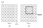
画面全体輝度算出部203は、図3(a)のような、領域(I,J)ごとの重みW(I,J)を用い、以下の式(1)に示す加重平均演算により画面全体輝度Yallを算出する。
Yall=ΣY(I,J)×W(I,J)/ΣW(I,J) (1)
ただしI,J=0〜5
The overall screen
Yall = ΣY (I, J) × W (I, J) / ΣW (I, J) (1)
However, I, J = 0-5
画面上部輝度算出部204は、領域ごとの輝度値Y(I,J)をもとに画面上部輝度値Yupperを式(2)に従って求める。
Yupper=(Y(0,0)+Y(1,0)+Y(2,0)+Y(3,0)+Y(4,0)+Y(5,0))/6 式(2)
The screen upper
Yupper = (Y (0,0) + Y (1,0) + Y (2,0) + Y (3,0) + Y (4,0) + Y (5,0)) / 6 Equation (2)
主被写体輝度算出部205は、主被写体領域の輝度値を求める。本実施形態では、図1の顔検出回路120により顔が検出された場合、顔領域の大きさ及び位置が露出制御回路160に供給される。主被写体輝度算出部205は、検出された顔領域が1つであればその顔領域を、検出された顔領域が複数ある場合はその位置と大きさ(又はユーザの選択)により1つを主被写体領域として決定する。そして、主被写体輝度算出部205は、主被写体領域に含まれる画素の平均輝度値を主被写体輝度Ymainとして求める。
The main subject
たとえば検出された顔領域が1つで、かつ図3(b)のような位置にある場合、主被写体輝度算出部205は、以下の式(3)のように、顔検出領域に全体が含まれる4つの領域の画素値の平均輝度を主被写体輝度Ymainとしてを求める。
Ymain=(Y(1,2)+Y(1,3)+Y(2,2)+Y(2,3))/4 式(3)
For example, when there is one detected face area and the position is as shown in FIG. 3B, the main subject
Ymain = (Y (1,2) + Y (1,3) + Y (2,2) + Y (2,3)) / 4 Formula (3)
また、主被写体輝度算出部205は、顔検出回路120で顔が検出されなかった場合は、画面中心に主被写体があると仮定して、以下の式(4)のように、画面中心部の平均輝度値を主被写体輝度Ymainとして求める。すなわち、
Ymain=(Y(2,2)+Y(2,3)+Y(3,2)+Y(3,3))/4 式(4)
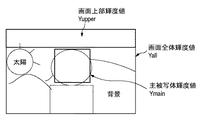
画面全体輝度Yall、画面上部輝度値Yupper、および主被写体輝度Ymainは、それぞれ露出制御値決定部206に供給される。
なお、画面全体輝度Yall、画面上部輝度値Yupper、および主被写体輝度Ymainが具体的な画像においてどのような領域の輝度値に対応するかの例を、図4に示す。
Further, the main subject
Ymain = (Y (2,2) + Y (2,3) + Y (3,2) + Y (3,3)) / 4 Formula (4)
The entire screen luminance Yall, the upper screen luminance value Yupper, and the main subject luminance Ymain are supplied to the exposure control
FIG. 4 shows an example of what region brightness value corresponds to the entire screen brightness Yall, the screen upper brightness value Yupper, and the main subject brightness Ymain in a specific image.
露出制御値決定部206は、以下のように画面全体輝度Yallおよび主被写体輝度Ymainの各々と目標露出値との差分を、露出制御データDeltaBvとして求める。通常の自動露出制御では、画面上部輝度値Yupperは用いられない。
顔が検出されている場合
DeltaBv =Log2(Ymain/Yref) 式(5)
顔が検出されていない場合
DeltaBv =Log2(Yall/Yref) 式(6)
ただしYrefは目標輝度値
The exposure control
When a face is detected DeltaBv = Log2 (Ymain / Yref) Equation (5)
When no face is detected DeltaBv = Log2 (Yall / Yref) Equation (6)
Yref is the target brightness value
ここで求められた露出制御データDeltaBvは目標輝度値(すなわち、適正輝度値)からの差分である。従って、輝度値を求めたRAW画像データ201を撮像したときの露出パラメータを、露出制御データDeltaBvを用いて補正して撮像することで、適正な明るさの画像を得ることが可能となる。
The exposure control data DeltaBv obtained here is a difference from the target luminance value (that is, the appropriate luminance value). Therefore, it is possible to obtain an image with appropriate brightness by correcting the exposure parameter when the
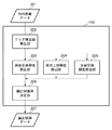
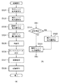
次に、図5(a)のフローチャートを参照して、本実施形態の撮像装置における、ダイナミックレンジ拡大処理を伴う撮像処理について説明する。
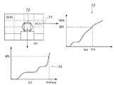
図5(a)に示す動作は、撮像スタンバイ時において、操作部112に含まれるシャッターボタンが全押しされ、撮像開始指示が入力されたことに応答して、システムコントローラ107が開始するものとする。なお、以下では、説明及び理解を容易にするため、図6(a)に示すように、顔検出回路120によって顔領域が1つだけ検出されている(すなわち、検出されている顔領域が主被写体領域である)ものとする。
Next, imaging processing with dynamic range expansion processing in the imaging apparatus of the present embodiment will be described with reference to the flowchart in FIG.
The operation shown in FIG. 5A is assumed to be started by the
まず、第1の算出手段としてのシステムコントローラ107は、以下のように第1ダイナミックレンジ拡大量を算出する(S501)。
まず、システムコントローラ107は、ヒストグラム作成回路130により、図6(a)〜図6(c)に示すように、主被写体領域72(ここでは顔領域)に含まれる画素の輝度値の累積ヒストグラム74を作成させる。また、システムコントローラ107は、画面を4×4に分割した領域71ごとの画素値の累積ヒストグラム73も、ヒストグラム作成回路130に作成させる。そして、システムコントローラ107は顔領域の累積ヒストグラム74を用いて、累積ヒストグラムが全体に対する所定割合(ここでは90%とする)となる輝度値YHiFaceを算出する。また同様に、分割した個々の領域71についても、累積ヒストグラム73が所定割合(ここでは80%とする)となる輝度値YHi(I,J)(I,J=0〜3)を求める。
ここで得られる値YHiFace及びYHi(I,J)の値が大きいほど白とび(高輝度)領域が多いことを意味する。
First, the
First, the
A larger value of the values YHiFace and YHi (I, J) obtained here means that there are more whiteout (high luminance) regions.
次にシステムコントローラ107は、YHiFace,YHi(I,J)をあらかじめ設定されている閾値と比較する。
ここで、閾値を、大きい方からTHHiFace、THMidFace、THLowFaceの3段階とすると、システムコントローラ107は、顔領域より計算されるダイナミックレンジ拡大量DpFaceを以下のように求める。ここでは、ダイナミックレンジ拡大量DpFaceを、露出段数により表している。
DpFace=3/3段 (YHiFace>THHiFaceの場合)
DpFace=2/3段 (THHiFace≧YHiFace>THMidFaceの場合)
DpFace=1/3段 (THMidFace≧YHiFace>THLowFaceの場合)
DpFace=0 (YHiFace≦THLowFaceの場合)
Next, the
Here, if the threshold value is THHiFace, THMidFace, and THLowFace from the largest, the
DpFace = 3/3 stage (when YHiFace> THHiFace)
DpFace = 2/3 stage (when THHiFace ≧ YHiFace> THMidFace)
DpFace = 1/3 stage (THMidFace ≧ YHiFace> THLowFace)
DpFace = 0 (when YHiFace ≦ THLowFace)
一方、システムコントローラ107は、YHi(I,J)をあらかじめ決定されている輝度閾値YhiThと比較し、YhiThを超える領域の数をカウントする。ここで、カウントした結果をYH_BNum、閾値を大きい方からThYH_BNum3、ThYH_BNum2、ThYH_BNum1の3段階とする。システムコントローラ107は、分割領域ヒストグラムから求められるダイナミックレンジ拡大量DpAreaを以下のように求める。ここでは、ダイナミックレンジ拡大量DpAreaを、露出段数により表している。
DpArea=3/3段 (YH_BNum>ThYH_BNum3の場合)
DpArea=2/3段 (ThYH_BNum3≧YH_BNum>ThYH_BNum2の場合)
DpArea=1/3段 (ThYH_BNum2≧YH_BNum>ThYH_BNum1の場合)
DpArea=0 (YH_BNum≦ThYH_BNum1の場合)
On the other hand, the
DpArea = 3/3 stage (when YH_BNum> ThYH_BNum3)
DpArea = 2/3 stage (when ThYH_BNum3 ≧ YH_BNum> ThYH_BNum2)
DpArea = 1/3 stage (When ThYH_BNum2 ≧ YH_BNum> ThYH_BNum1)
DpArea = 0 (when YH_BNum ≦ ThYH_BNum1)
そして、システムコントローラ107は、ダイナミックレンジ拡大量DpFaceとDpAreaを比較し、大きい値を第1ダイナミックレンジ拡大量Dp1とする。
すなわち、
Dp1=DpFace (DpFace>DpAreaの場合)
Dp1=DpArea (DpFace≦DpAreaの場合)
である。
このように、第1ダイナミックレンジ拡大量Dp1は主被写体領域のハイライト輝度が高いほど、分割領域のうちハイライト輝度が高い領域の数が多いほど大きくなる。
Then, the
That is,
Dp1 = DpFace (DpFace> DpArea)
Dp1 = DpArea (DpFace ≦ DpArea)
It is.
As described above, the first dynamic range expansion amount Dp1 increases as the highlight luminance of the main subject region increases and as the number of regions having high highlight luminance among the divided regions increases.
第1ダイナミックレンジ拡大量Dp1を算出すると、第2の算出手段としてのシステムコントローラ107は次に第2ダイナミックレンジ拡大量Dp2を算出する(S502)。
システムコントローラ107は、露出制御回路160で得られる画面全体輝度Yall、画面上部輝度値Yupper、および主被写体輝度Ymainをもとに第2ダイナミックレンジ拡大量Dp2を算出する。
When the first dynamic range expansion amount Dp1 is calculated, the
The
まず、システムコントローラ107は、画面全体輝度Yall、画面上部輝度値Yupper、および主被写体輝度Ymainを、それぞれ以下の式を用いて対応する露出段数DeltaBvAll、DeltaBvFace、DeltaBvMainに換算する。
DeltaBvAll=Log2(Yall/Yref)
DeltaBvUpper=Log2(Yupper/Yref)
DeltaBvMain=Log2(Ymain/Yref)
ここで、Yrefは目標輝度値である。
First, the
DeltaBvAll = Log2 (Yall / Yref)
DeltaBvUpper = Log2 (Yupper / Yref)
DeltaBvMain = Log2 (Ymain / Yref)
Here, Yref is a target luminance value.
次にシステムコントローラ107は、段数換算した値から、以下のようにして被写体と背景の差分値を求める。
DeltaBv01=DeltaBvAll−DeltaBvMain
DeltaBv02=DeltaBvUpper−DeltaBvMain
Next, the
DeltaBv01 = DeltaBvAll-DeltaBvMain
DeltaBv02 = DeltaBvUpper-DeltaBvMain
ここで求められるDeltaBv01は主被写体と画面全体の輝度の差分である。たとえば顔が検出されている場合は、顔領域の輝度が目標輝度値となるように、すなわちDeltaBvMainが0になるように自動露出制御されているため、DeltaBv01が大きいほど、背景が露出オーバーであると判別できる。また、DeltaBv02は主被写体と画面上部の輝度の差分である。一般に画面上部は空などの明るい被写体が撮像されていることが多く、DeltaBv02が大きいほど、画面上部に露出オーバーな被写体が撮像されていると判別できる。 DeltaBv01 obtained here is a difference in luminance between the main subject and the entire screen. For example, when a face is detected, automatic exposure control is performed so that the brightness of the face area becomes the target brightness value, that is, DeltaBvMain is 0. Therefore, the larger the DeltaBv01, the more the background is overexposed. Can be determined. DeltaBv02 is the difference in luminance between the main subject and the upper part of the screen. In general, a bright subject such as the sky is often imaged at the upper part of the screen, and it can be determined that an overexposed subject is imaged at the upper part of the screen as DeltaBv02 is larger.
DeltaBv01とDeltaBv02のより大きい値をDeltaBvMaxとする。すなわち、
DeltaBvMax=DeltaBv01 (DeltaBv01>DeltaBv02の場合)
DeltaBvMax=DeltaBv02 (DeltaBv02≧DeltaBv01の場合)
である。
The larger value of DeltaBv01 and DeltaBv02 is defined as DeltaBvMax. That is,
DeltaBvMax = DeltaBv01 (when DeltaBv01> DeltaBv02)
DeltaBvMax = DeltaBv02 (when DeltaBv02 ≧ DeltaBv01)
It is.
そして、システムコントローラ107は、DeltaBvMaxの大きさを6つの閾値(大きい方からDeltaMaxTh6〜DeltaMaxTh1とする)と比較し、最大2段分、1/3刻みの第2ダイナミックレンジ拡大量Dp2を算出する。
Dp2=6/3段 (DeltaBvMax>DeltaMaxTh6の場合)
Dp2=5/3段 (DeltaMaxTh6≧DeltaBvMax>DeltaMaxTh5の場合)
Dp2=4/3段 (DeltaMaxTh5≧DeltaBvMax>DeltaMaxTh4の場合)
Dp2=3/3段 (DeltaMaxTh4≧DeltaBvMax>DeltaMaxTh3の場合)
Dp2=2/3段 (DeltaMaxTh3≧DeltaBvMax>DeltaMaxTh2の場合)
Dp2=1/3段 (DeltaMaxTh2≧DeltaBvMax>DeltaMaxTh1の場合)
Dp2=0 (DeltaBvMax≦DeltaMaxTh1の場合)
Then, the
Dp2 = 6/3 stage (when DeltaBvMax> DeltaMaxTh6)
Dp2 = 5/3 stage (when DeltaMaxTh6 ≧ DeltaBvMax> DeltaMaxTh5)
Dp2 = 4/3 stage (when DeltaMaxTh5 ≧ DeltaBvMax> DeltaMaxTh4)
Dp2 = 3/3 stage (when DeltaMaxTh4 ≧ DeltaBvMax> DeltaMaxTh3)
Dp2 = 2/3 stage (when DeltaMaxTh3 ≧ DeltaBvMax> DeltaMaxTh2)
Dp2 = 1/3 stage (when DeltaMaxTh2 ≧ DeltaBvMax> DeltaMaxTh1)
Dp2 = 0 (when DeltaBvMax ≦ DeltaMaxTh1)
本実施形態において、DeltaMaxTh6=6/3、DeltaMaxTh5=5/3、DeltaMaxTh4=4/3、DeltaMaxTh3=3/3、DeltaMaxTh2=2/3、DeltaMaxTh1=1/3とする。 In the present embodiment, DeltaMaxTh6 = 6/3, DeltaMaxTh5 = 5/3, DeltaMaxTh4 = 4/3, DeltaMaxTh3 = 3/3, DeltaMaxTh2 = 2/3, and DeltaMaxTh1 = 1/3.
本実施形態では、第2ダイナミックレンジ拡大量Dp2の上限値を、第1ダイナミックレンジ拡大量の上限値より大きい2段分にしている。これは、DeltaBvMaxが1段より大きくなる場合は、逆光のようなシーンが多く、より広いダイナミックレンジ拡大が必要となるためである。 In the present embodiment, the upper limit value of the second dynamic range expansion amount Dp2 is set to two stages larger than the upper limit value of the first dynamic range expansion amount. This is because when DeltaBvMax is larger than one stage, there are many scenes such as backlight, and a wider dynamic range needs to be expanded.
第1ダイナミックレンジ拡大量Dp1と第2ダイナミックレンジ拡大量Dp2を算出すると、第3の算出手段としてのシステムコントローラ107は、最終ダイナミックレンジ拡大量Dpを以下のように算出する(S503)。
Dp=Dp1 (Dp1>Dp2の場合)
Dp=Dp2 (Dp1≦Dp2の場合)
When the first dynamic range expansion amount Dp1 and the second dynamic range expansion amount Dp2 are calculated, the
Dp = Dp1 (when Dp1> Dp2)
Dp = Dp2 (when Dp1 ≦ Dp2)
次に、決定手段としてのシステムコントローラ107は、AFE回路150に、最終ダイナミックレンジ拡大量Dpに応じた感度設定値としてゲイン量を設定する。また、システムコントローラ107は、AFE回路150での感度設定のみによってはダイナミックレンジ拡大量Dpを実現できない場合、露出補正量を算出する(S504)。
Next, the
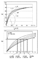
S504における動作についてさらに説明する。図7(a)は、本実施形態におけるダイナミックレンジ(Dレンジ)の概念図を表す図である。 The operation in S504 will be further described. FIG. 7A is a diagram illustrating a conceptual diagram of a dynamic range (D range) in the present embodiment.
本実施形態において、ダイナミックレンジとは、適正輝度に対する撮像素子の飽和信号量輝度の比率と定義する。適正輝度とは、自動露出制御(AE)を行う際の輝度目標値レベル(Yref)であり、例えばAEのモードが平均測光モードであれば、画面輝度の平均値に、顔AEモードであれば顔領域輝度の平均値に相当する。
従って、
ダイナミックレンジ=センサー飽和信号量輝度/AE目標値
と定義することができる。
In the present embodiment, the dynamic range is defined as the ratio of the saturation signal amount luminance of the image sensor to the appropriate luminance. The appropriate brightness is a brightness target value level (Yref) when performing automatic exposure control (AE). For example, if the AE mode is the average metering mode, the screen brightness average value is set to the face AE mode. This corresponds to the average value of the face area luminance.
Therefore,
Dynamic range = sensor saturation signal amount luminance / AE target value.
なお、ここでのAE目標値はAFE回路150で感度調整を行う前の、撮像素子101の出力信号に基づくAE目標値である。
AE目標値は、AEのモードに応じて変化してよく、評価測光モードやスポット測光モードであっても、それぞれのモードによるAE目標値を用いることができる。
Here, the AE target value is an AE target value based on the output signal of the
The AE target value may change according to the AE mode, and the AE target value in each mode can be used even in the evaluation photometry mode or the spot photometry mode.
図7(b)は、AE目標値、飽和信号値およびダイナミックレンジの関係例を示す図である。
図7(b)から、AE目標値を下げることにより、ダイナミックレンジ量を大きくしていくことが可能であることがわかる。すなわち、ダイナミックレンジ拡大を行うためには、最終ダイナミックレンジ拡大量Dp分だけ、露出アンダーで撮像する必要があることがわかる。
FIG. 7B is a diagram illustrating a relationship example between the AE target value, the saturation signal value, and the dynamic range.
FIG. 7B shows that the dynamic range amount can be increased by lowering the AE target value. That is, in order to perform the dynamic range expansion, it is necessary to image underexposed for the final dynamic range expansion amount Dp.
S504でシステムコントローラ107は、最終ダイナミックレンジ拡大量Dp、すなわちAE目標値の低減量が、AFE回路150における感度調整(CDSゲイン回路およびVGAゲイン回路の制御)により実現可能であるか否か判定する。この判定は、AFE回路150で調整可能な感度の範囲とS503で算出した最終ダイナミックレンジ拡大量Dpとを比較して行うことができる。最終ダイナミックレンジ拡大量Dpに相当する感度の低減(ゲインの低減)ができない場合、システムコントローラ107は、AFE回路150での感度調整のみでは最終ダイナミックレンジ拡大量Dpを実現できないと判断する。
In S504, the
AFE回路150における感度調整で最終ダイナミックレンジ拡大量Dpを実現可能な場合、システムコントローラ107は、最終ダイナミックレンジ拡大量Dpを実現するゲイン設定を算出する。なお、AFE回路150のCDSゲインとVGAゲインとをどのように組み合わせて最終ダイナミックレンジ拡大量Dpを実現するかには特に制限はなく、任意の組み合わせで設定可能である。
When the final dynamic range expansion amount Dp can be realized by sensitivity adjustment in the
一方、AFE回路150での感度調整だけでは最終ダイナミックレンジ拡大量Dpを実現できないと判断される場合、システムコントローラ107は、感度調整を行っても依然として不足する感度低減量を実現するための露出補正量を算出する。
On the other hand, when it is determined that the final dynamic range expansion amount Dp cannot be realized only by the sensitivity adjustment in the
ここでの露出補正はマイナス補正であり、絞りを小さく(絞り値を大きく)する、シャッター速度を早くする、減光フィルタ(NDフィルタ)を挿入するといった、一般的な方法によって実現することができる。 The exposure correction here is a minus correction, and can be realized by a general method such as reducing the aperture (increasing the aperture value), increasing the shutter speed, or inserting a neutral density filter (ND filter). .
システムコントローラ107は、AFE回路150のCDSゲインおよびVGAゲインを設定する。また、露出補正を行う場合には、AE結果に応じた露出パラメータ(シャッター速度、絞り値、NDフィルタの使用有無の設定など)を、露出補正量に応じて変更し、レンズ装置200に設定する。
The
次に、撮像制御手段としてのシステムコントローラ107は、静止画撮像(本露光)を行う(S505)。撮像により得られたRAW画像データはバッファメモリ103に記憶される。
Next, the
システムコントローラ107は、RAW画像データに対して所謂現像処理を適用するするために必要な各種パラメータを信号処理回路140に設定する。この場合、最終ダイナミックレンジ拡大量Dpに応じた段数分て露出アンダーな撮像条件で撮像されているため、システムコントローラ107は、明るさを補うようなガンマパラメータを信号処理回路140に設定する(S506)。
The
図8は、本実施形態の信号処理回路140におけるガンマ補正特性の設定例を示す図である。
FIG. 8 is a diagram illustrating a setting example of gamma correction characteristics in the
ダイナミックレンジ拡大量を、通常(0/3段)、+1/3段、+2/3段、+3/3段分の4段階に設定した場合のガンマ特性(明るさ補正量)の設定例を示している。なお、1段分を超えてダイナミックレンジを拡大する場合にも、同様な考え方で設定すればよい。 An example of setting the gamma characteristic (brightness correction amount) when the dynamic range expansion amount is set to four levels of normal (0/3 step), +1/3 step, +2/3 step, and +3/3 step. ing. It should be noted that the same concept may be used when expanding the dynamic range beyond one stage.
ここで各ダイナミックレンジ拡大量に対応したAE目標値は図7(b)で示したものと同値である。図8に示すように、各ダイナミックレンジ拡大時におけるAE目標値に対してガンマ補正した後のAE目標値が、ダイナミックレンジ拡大量によらず、ダイナミックレンジ拡大をしない通常のAE目標値となるようにガンマ補正特性を設定する。すなわち、最終ダイナミックレンジ拡大量Dpに応じて、あらかじめ用意されたガンマ補正特性が選択的に設定される。 Here, the AE target value corresponding to each dynamic range expansion amount is the same as that shown in FIG. As shown in FIG. 8, the AE target value after performing gamma correction on the AE target value at the time of each dynamic range expansion becomes a normal AE target value that does not expand the dynamic range regardless of the dynamic range expansion amount. Set the gamma correction characteristics to. That is, a gamma correction characteristic prepared in advance is selectively set according to the final dynamic range expansion amount Dp.
図7(a)および図7(b)を用いて説明したように、AE目標値を下げることで、ダイナミックレンジを拡大することができる。しかし、単純にAE目標値を下げると、露出アンダーとなり、撮像画像が暗くなってしまう。そのため、ダイナミックレンジ拡大量に応じて、撮像後の画像データを明るくするように信号処理回路140でガンマ補正することにより、撮像画像の明るさ(露出)を適正にしながら、ダイナミックレンジを拡大することができる。
As described with reference to FIGS. 7A and 7B, the dynamic range can be expanded by lowering the AE target value. However, simply lowering the AE target value results in underexposure and the captured image becomes dark. Therefore, the dynamic range can be expanded while the brightness (exposure) of the captured image is made appropriate by performing gamma correction by the
なお、本実施形態では、AE目標値を下げたことによる撮像画像の輝度低下を、ガンマ補正により補償する構成について例示したが、ルックアップテーブルなど別の手段を用いて同様の輝度補正を行ってもよい。 In the present embodiment, the configuration in which the decrease in luminance of the captured image due to the decrease in the AE target value is compensated by gamma correction is described, but the same luminance correction is performed using another means such as a lookup table. Also good.
ガンマ補正特性が設定されると、信号処理回路140はRAW画像データの現像処理を行い、YUV形式の画像データをバッファメモリ103に格納する(S507)。信号処理回路140で現像処理された画像データは、圧縮・伸長回路104によって例えばJPEG形式のファイルに符号化され、記録装置105によって記録媒体106に記録される(S508)。
When the gamma correction characteristic is set, the
本実施形態において、第1ダイナミックレンジ拡大量の決定に用いる分割領域ごとのヒストグラムを、画面を4×4に分割した16の領域について作成した。しかし、分割数はこれに限られるものではなく、M×N(M、Nは任意の整数)であってよい。 In the present embodiment, a histogram for each divided region used for determining the first dynamic range expansion amount is created for 16 regions obtained by dividing the screen into 4 × 4. However, the number of divisions is not limited to this, and may be M × N (M and N are arbitrary integers).
また、顔領域のヒストグラムと分割領域ごとのヒストグラムの両方を使用して第1ダイナミックレンジ拡大量を決定したが、演算処理の簡略化のため、どちらか一方のみを用いて決定してもよい。また、他の情報(全体ヒストグラム情報、非等分割領域ヒストグラム等)を使って拡大量を決定してもよい。 Further, the first dynamic range expansion amount is determined using both the histogram of the face region and the histogram of each divided region. However, for simplification of the arithmetic processing, only one of them may be determined. Also, the enlargement amount may be determined using other information (whole histogram information, non-uniformly divided region histogram, etc.).
また、画面全体輝度、画面上部輝度、主被写体輝度を用いて第2ダイナミックレンジ拡大量を決定したが、画面左右輝度、画面下部輝度などと主被写体輝度との輝度差や、他の画面内の領域間の輝度差を用いて決定してもよい。 In addition, the second dynamic range expansion amount was determined using the overall screen brightness, the upper screen brightness, and the main subject brightness. However, the difference between the left and right screen brightness, the lower screen brightness, etc. and the main subject brightness, You may determine using the luminance difference between area | regions.
また、第1ダイナミックレンジ拡大量と第2ダイナミックレンジ拡大量を求めるにあたり、ノイズの増加を考慮して、高感度撮像時には低感度撮像時に比べてダイナミックレンジ拡大量を低減するようにしてもよい。具体例としては、設定されている撮像感度に応じて各閾値(THHiFace、THMidFace、THLowFace、YhiTh、DeltaMax6〜DeltaMax1)の値が大きくなるように変更すればよい。 Further, in obtaining the first dynamic range expansion amount and the second dynamic range expansion amount, the dynamic range expansion amount may be reduced in high-sensitivity imaging compared to low-sensitivity imaging in consideration of an increase in noise. As a specific example, the threshold values (THHiFace, THMidFace, THLowFace, YhiTh, DeltaMax6 to DeltaMax1) may be changed in accordance with the set imaging sensitivity.
以上説明したように、本実施形態によれば、主被写体と画像全体の少なくとも一方の輝度が高い多いほど大きくなる第1ダイナミックレンジ拡大量と、画面内の領域間の輝度の差が大きいほど大きくなる第2ダイナミックレンジ拡大量を求める。そして、いずれか大きい方のダイナミックレンジ拡大量を適用する。これにより、画面の一部の白い被写体が白とびするようなシーンに対しては第1ダイナミックレンジ拡大量が、逆光シーンのように主被写体と背景の輝度差が大きいシーンについては第2ダイナミックレンジ拡大量が適応的に決定される。そのため、シーンに応じたダイナミックレンジ拡大量を自動的に設定することができる。 As described above, according to the present embodiment, the first dynamic range expansion amount that increases as the luminance of at least one of the main subject and the entire image increases, and increases as the luminance difference between the regions in the screen increases. The second dynamic range expansion amount is obtained. Then, the larger dynamic range expansion amount is applied. As a result, the first dynamic range expansion amount is applied to a scene in which a white subject on a part of the screen is blown out, and the second dynamic range is applied to a scene having a large luminance difference between the main subject and the background, such as a backlight scene. The amount of enlargement is determined adaptively. Therefore, the dynamic range expansion amount can be automatically set according to the scene.
また、第1ダイナミックレンジ拡大量の上限値よりも第2ダイナミックレンジ拡大量の上限値を大きく設定している。そのため、砂浜や雪山のような白い被写体が含まれるようなシーンにおいて、ダイナミックレンジ拡大量が大きいことによるコントラスト低下を抑制できる。また、人物を逆光で撮像した場合には、より大きなダイナミックレンジ拡大量が適用可能となるため、主被写体である人物の顔の明るさが適正で、かつ背景の白とびをなるべく抑えることが可能になる。 Further, the upper limit value of the second dynamic range expansion amount is set larger than the upper limit value of the first dynamic range expansion amount. Therefore, in a scene where a white subject such as a sandy beach or a snowy mountain is included, it is possible to suppress a decrease in contrast due to a large dynamic range expansion amount. In addition, when a person is imaged in backlight, a larger dynamic range expansion amount can be applied, so that the face brightness of the person who is the main subject is appropriate and the overexposure of the background can be suppressed as much as possible. become.
(第2の実施形態)
次に、本発明の第2の実施形態について、第1の実施形態と異なる部分のみ説明する。説明がない部分に関しては、第1の実施形態と同じである。
図5(b)は、本実施形態の撮像装置における、ダイナミックレンジ拡大処理を伴う撮像処理について説明するフローチャートであり、第1の実施形態と異なる処理のみ記載している。
(Second Embodiment)
Next, only a different part from 1st Embodiment is demonstrated about 2nd Embodiment of this invention. The parts not described are the same as those in the first embodiment.
FIG. 5B is a flowchart for describing an imaging process with a dynamic range expansion process in the imaging apparatus of the present embodiment, and describes only a process different from the first embodiment.
本実施形態では、
・S501の後にS510の逆光判定処理が追加され、逆光と判定された場合においてのみ第2ダイナミックレンジ拡大算出処理が実施されること、
・逆光と判定されなかった場合はS503で第1ダイナミックレンジ拡大量のみから最終ダイナミックレンジ拡大量を算出すること、が第1の実施形態と異なる。
In this embodiment,
The backlight determination process of S510 is added after S501, and the second dynamic range expansion calculation process is performed only when it is determined to be backlight,
If it is not determined to be backlight, the final dynamic range expansion amount is calculated from only the first dynamic range expansion amount in S503, which is different from the first embodiment.
S510における逆光判定処理について説明する。
逆光判定は、露出制御回路160の画面全体輝度算出部203、画面上部輝度算出部204、主被写体輝度算出部205で求められる画面全体輝度Yall、画面上部輝度値Yupper、および主被写体輝度Ymainを用いて行う。
The backlight determination process in S510 will be described.
The backlight determination uses the entire screen
システムコントローラ107は、画面全体輝度Yall、画面上部輝度値Yupper、および主被写体輝度Ymainを、以下の式を用いて対応する露出段数DeltaBvAll、DeltaBvFace、DeltaBvMainに換算する。
DeltaBvAll=Log2(Yall/Yref)
DeltaBvUpper=Log2(Yupper/Yref)
DeltaBvMain=Log2(Ymain/Yref)
ここで、Yrefは目標輝度値である。
The
DeltaBvAll = Log2 (Yall / Yref)
DeltaBvUpper = Log2 (Yupper / Yref)
DeltaBvMain = Log2 (Ymain / Yref)
Here, Yref is a target luminance value.
次にシステムコントローラ107は、段数換算した値から、以下のようにして被写体と背景の差分値を求める。
DeltaBv01=DeltaBvAll−DeltaBvMain
DeltaBv02=DeltaBvUpper−DeltaBvMain
Next, the
DeltaBv01 = DeltaBvAll-DeltaBvMain
DeltaBv02 = DeltaBvUpper-DeltaBvMain
そして、システムコントローラ107は、算出したDeltaBv01、DeltaBv02を、それぞれあらかじめ設定されている閾値BackLightTh01、BackLightTh02と比較する。システムコントローラ107は、以下の2つの条件のどちらかが満たされた場合に逆光と判定する。
条件1: DeltaBv01>BackLightTh01
条件2: DeltaBv02>BackLightTh02
Then, the
Condition 1: DeltaBv01> BackLightTh01
Condition 2: DeltaBv02> BackLightTh02
条件1は、画面全体輝度が主被写体輝度に対し、一定値BackLightTh01より大きいことを意味する。また条件2は、画面上部輝度が主被写体輝度に対して一定値BackLightTh02より大きいことを意味する。いずれの場合も、主被写体よりも背景の輝度が一定値を超えて高いことを意味するため、逆光であると判定することができる。なお、閾値BackLightTh01、BackLightTh02の値は例えば経験的に求めることができる。
なお、本実施形態で、システムコントローラ107は、S510で逆光と判定されず、第2ダイナミックレンジ拡大量Dp2を算出しなかった場合には、S503において、第1ダイナミックレンジ拡大量Dp1を最終ダイナミックレンジ拡大量Dpとする。
In this embodiment, if the
なお、S510で逆光と判定して第2ダイナミックレンジ拡大量Dp2を算出する場合、DeltaBv01及びDeltaBv02を改めて算出する必要はなく、S510で求めた値を用いることができる。 When the second dynamic range expansion amount Dp2 is calculated by determining that the light is backlit in S510, it is not necessary to calculate DeltaBv01 and DeltaBv02 again, and the value obtained in S510 can be used.
本実施形態においては、画面全体輝度、画面上部輝度、主被写体輝度の関係から逆光の判定をしているが、逆光判定方法としてはこれに限られるものではない。例えば、画面全体のヒストグラム情報を用いて、ハイライト部、ダーク部の画面全体に対する比率等の情報から逆光を判別してもよい。 In the present embodiment, the backlight is determined based on the relationship between the overall screen brightness, the screen upper brightness, and the main subject brightness. However, the backlight determination method is not limited to this. For example, the backlight may be determined from information such as the ratio of the highlight portion and the dark portion to the entire screen using histogram information of the entire screen.
また、本実施形態においては、第1ダイナミックレンジ拡大量を算出した後に逆光判定を実施するようにしているが、第1ダイナミックレンジ拡大量を算出する前に逆光判定を実施してもよい。この場合、逆光と判定されなければ第1ダイナミックレンジ拡大量のみを算出して最終ダイナミックレンジ拡大量とし、逆光と判定された場合のみ、第1ダイナミックレンジ拡大量算出と第2ダイナミックレンジ拡大量算出を実施するようにしてもよい。
本実施形態によれば、より少ない処理負荷で、第1の実施形態と同様の効果を得ることができる。
In the present embodiment, the backlight determination is performed after the first dynamic range expansion amount is calculated, but the backlight determination may be performed before the first dynamic range expansion amount is calculated. In this case, if it is not determined to be backlight, only the first dynamic range expansion amount is calculated to be the final dynamic range expansion amount, and only when it is determined to be backlight, the first dynamic range expansion amount calculation and the second dynamic range expansion amount calculation are performed. May be implemented.
According to the present embodiment, the same effect as that of the first embodiment can be obtained with a smaller processing load.
以上、本発明をその好適な実施形態に基づいて詳述してきたが、本発明はこれら特定の実施形態に限られるものではなく、この発明の要旨を逸脱しない範囲の様々な形態も本発明に含まれる。上述の実施形態の一部を適宜組み合わせてもよい。 Although the present invention has been described in detail based on preferred embodiments thereof, the present invention is not limited to these specific embodiments, and various forms within the scope of the present invention are also included in the present invention. included. A part of the above-described embodiments may be appropriately combined.
また、本発明は、以下の処理を実行することによっても実現される。即ち、上述した実施形態の機能を実現するソフトウェア(プログラム)を、ネットワーク又は各種記憶媒体を介してシステム或いは装置に供給し、そのシステム或いは装置のコンピュータ(またはCPUやMPU等)がプログラムを読み出して実行する処理である。 The present invention can also be realized by executing the following processing. That is, software (program) that realizes the functions of the above-described embodiments is supplied to a system or apparatus via a network or various storage media, and a computer (or CPU, MPU, or the like) of the system or apparatus reads the program. It is a process to be executed.
Claims (8)
前記撮像手段により取得された画像データの輝度のヒストグラムに基づいて第1の補正量を算出する第1の算出手段と、
前記撮像手段により取得された画像データの領域間の輝度差に基づいて第2の補正量を算出する第2の算出手段と、
前記第1の補正量及び第2の補正量を比較した結果に基づいて、撮像感度及び露出の少なくとも一方の低減量を決定する決定手段と、
前記決定手段により決定された前記低減量に基づいて前記撮像手段により撮像を行い、取得された画像データに対して前記低減量を補う信号処理を適用する補正手段とを有することを特徴とする撮像装置。 An imaging means for imaging and acquiring image data;
First calculation means for calculating a first correction amount based on a luminance histogram of the image data acquired by the imaging means ;
Second calculating means for calculating a second correction amount based on a luminance difference between areas of the image data acquired by the imaging means ;
Determining means for determining a reduction amount of at least one of imaging sensitivity and exposure based on a result of comparing the first correction amount and the second correction amount ;
Before SL captures an image by the imaging unit based on the reduction amount determined by the determining means, and having a correction means for applying said reduction amount signal processing to compensate for the acquired image data Imaging device.
前記第2の算出手段は、前記判定手段により逆光シーンであると判定された場合のみ前記第2の補正量を算出し、
前記決定手段は、前記判定手段により逆光シーンでないと判定された場合には、前記第1の補正量に基づいて前記低減量を決定することを特徴とする請求項1乃至請求項6のいずれか1項に記載の撮像装置。 A determination unit for determining whether an image based on the image data acquired by the imaging unit is a backlight scene, based on a luminance difference between regions of the image data ;
The second calculation means calculates the second correction amount only when the determination means determines that the scene is a backlight scene,
Said determining means, if it is determined not to be a backlit scene by the determining means, any one of claims 1 to 6, characterized in that to determine the reduction amount based on the first correction amount The imaging apparatus according to item 1.
第1の算出手段が、前記撮像手段により取得された画像データの輝度のヒストグラムに基づいて第1の補正量を算出する第1の算出工程と、
第2の算出手段が、前記撮像手段により取得された画像データの領域間の輝度差に基づいて第2の補正量を算出する第2の算出工程と、
決定手段が、前記第1の補正量及び第2の補正量を比較した結果に基づいて、撮像感度及び露出の少なくとも一方の低減量を決定する決定工程と、
補正手段が、前記決定工程で決定された前記低減量に基づいて前記撮像手段により取得された画像データに対して前記低減量を補う信号処理を適用する補正工程とを有することを特徴とする撮像装置の制御方法。 A method for controlling an imaging apparatus having an imaging means for performing imaging and acquiring image data,
A first calculation step in which a first calculation unit calculates a first correction amount based on a luminance histogram of the image data acquired by the imaging unit ;
A second calculation step in which a second calculation unit calculates a second correction amount based on a luminance difference between regions of the image data acquired by the imaging unit ;
A determination step in which a determination unit determines a reduction amount of at least one of the imaging sensitivity and the exposure based on a result of comparing the first correction amount and the second correction amount ;
Correcting means, and having a correction step of applying said reduction amount signal processing to compensate for the acquired image data by the imaging unit based on the reduction amount determined in the previous SL determining step Control method of imaging apparatus.
Priority Applications (1)
| Application Number | Priority Date | Filing Date | Title |
|---|---|---|---|
| JP2009201093A JP5351663B2 (en) | 2009-08-31 | 2009-08-31 | Imaging apparatus and control method thereof |
Applications Claiming Priority (1)
| Application Number | Priority Date | Filing Date | Title |
|---|---|---|---|
| JP2009201093A JP5351663B2 (en) | 2009-08-31 | 2009-08-31 | Imaging apparatus and control method thereof |
Publications (3)
| Publication Number | Publication Date |
|---|---|
| JP2011055171A JP2011055171A (en) | 2011-03-17 |
| JP2011055171A5 JP2011055171A5 (en) | 2012-10-18 |
| JP5351663B2 true JP5351663B2 (en) | 2013-11-27 |
Family
ID=43943747
Family Applications (1)
| Application Number | Title | Priority Date | Filing Date |
|---|---|---|---|
| JP2009201093A Active JP5351663B2 (en) | 2009-08-31 | 2009-08-31 | Imaging apparatus and control method thereof |
Country Status (1)
| Country | Link |
|---|---|
| JP (1) | JP5351663B2 (en) |
Families Citing this family (1)
| Publication number | Priority date | Publication date | Assignee | Title |
|---|---|---|---|---|
| JP6250970B2 (en) * | 2013-07-30 | 2017-12-20 | キヤノン株式会社 | Image processing apparatus, imaging apparatus, image processing method, program, and recording medium |
Family Cites Families (5)
| Publication number | Priority date | Publication date | Assignee | Title |
|---|---|---|---|---|
| JP4269699B2 (en) * | 2003-01-24 | 2009-05-27 | 株式会社ニコン | Electronic camera |
| JP4360318B2 (en) * | 2004-11-29 | 2009-11-11 | 株式会社ニコン | Digital still camera |
| JP2007027967A (en) * | 2005-07-13 | 2007-02-01 | Fujifilm Holdings Corp | Imaging device |
| JP4687492B2 (en) * | 2006-02-14 | 2011-05-25 | 株式会社ニコン | Camera, imaging method, exposure calculation device, and program |
| JP4914300B2 (en) * | 2007-07-04 | 2012-04-11 | 富士フイルム株式会社 | Imaging apparatus and imaging control method |
-
2009
- 2009-08-31 JP JP2009201093A patent/JP5351663B2/en active Active
Also Published As
| Publication number | Publication date |
|---|---|
| JP2011055171A (en) | 2011-03-17 |
Similar Documents
| Publication | Publication Date | Title |
|---|---|---|
| US8355059B2 (en) | Image capturing apparatus and control method thereof | |
| US10412296B2 (en) | Camera using preview image to select exposure | |
| US9077905B2 (en) | Image capturing apparatus and control method thereof | |
| US8059187B2 (en) | Image capturing apparatus | |
| JP6720881B2 (en) | Image processing apparatus and image processing method | |
| JP6521776B2 (en) | Image processing apparatus, image processing method | |
| US11245857B2 (en) | Apparatus for generating high-dynamic-range image, method, and storage medium | |
| US8493458B2 (en) | Image capture apparatus and image capturing method | |
| JP4999871B2 (en) | Imaging apparatus and control method thereof | |
| JP6873679B2 (en) | Imaging device, control method and program of imaging device | |
| JP2009010616A (en) | Imaging apparatus and image output control method | |
| JP6786273B2 (en) | Image processing equipment, image processing methods, and programs | |
| JP5048599B2 (en) | Imaging device | |
| US8102446B2 (en) | Image capturing system and image processing method for applying grayscale conversion to a video signal, and computer-readable recording medium having recorded thereon an image processing program for applying grayscale conversion to a video signal | |
| JP2014179920A (en) | Imaging apparatus, control method thereof, program, and storage medium | |
| JP2010183460A (en) | Image capturing apparatus and method of controlling the same | |
| JP2002288650A (en) | Image processing apparatus and digital camera, image processing method, recording medium | |
| JP5335964B2 (en) | Imaging apparatus and control method thereof | |
| JP5351663B2 (en) | Imaging apparatus and control method thereof | |
| JP2010183461A (en) | Image capturing apparatus and method of controlling the same | |
| JP2015037222A (en) | Image processing apparatus, imaging apparatus, control method, and program | |
| JP7646395B2 (en) | Image capture device, image capture device control method, and program | |
| JP5789330B2 (en) | Imaging apparatus and control method thereof | |
| JP6849351B2 (en) | Image processing equipment, image processing methods, and programs | |
| JP2014121018A (en) | Imaging apparatus and control method for the same |
Legal Events
| Date | Code | Title | Description |
|---|---|---|---|
| A521 | Request for written amendment filed |
Free format text: JAPANESE INTERMEDIATE CODE: A523 Effective date: 20120830 |
|
| A621 | Written request for application examination |
Free format text: JAPANESE INTERMEDIATE CODE: A621 Effective date: 20120830 |
|
| A977 | Report on retrieval |
Free format text: JAPANESE INTERMEDIATE CODE: A971007 Effective date: 20130723 |
|
| TRDD | Decision of grant or rejection written | ||
| A01 | Written decision to grant a patent or to grant a registration (utility model) |
Free format text: JAPANESE INTERMEDIATE CODE: A01 Effective date: 20130726 |
|
| A61 | First payment of annual fees (during grant procedure) |
Free format text: JAPANESE INTERMEDIATE CODE: A61 Effective date: 20130823 |
|
| R151 | Written notification of patent or utility model registration |
Ref document number: 5351663 Country of ref document: JP Free format text: JAPANESE INTERMEDIATE CODE: R151 |