JP5349768B2 - Vibration wave drive - Google Patents
Vibration wave drive Download PDFInfo
- Publication number
- JP5349768B2 JP5349768B2 JP2007169142A JP2007169142A JP5349768B2 JP 5349768 B2 JP5349768 B2 JP 5349768B2 JP 2007169142 A JP2007169142 A JP 2007169142A JP 2007169142 A JP2007169142 A JP 2007169142A JP 5349768 B2 JP5349768 B2 JP 5349768B2
- Authority
- JP
- Japan
- Prior art keywords
- vibrator
- permanent magnet
- driven body
- force
- friction
- Prior art date
- Legal status (The legal status is an assumption and is not a legal conclusion. Google has not performed a legal analysis and makes no representation as to the accuracy of the status listed.)
- Active
Links
Images


Description
本発明は、振動波駆動装置に関し、特に小型のリニア型超音波モータに適用して好適な振動波駆動装置に関する。 The present invention relates to a vibration wave driving device, and more particularly to a vibration wave driving device suitable for application to a small linear ultrasonic motor.
従来、振動子に励起した超音波の機械的振動により被駆動体を駆動する超音波モータがある。超音波モータとしては、回転型超音波モータやリニア型超音波モータなどの種々の構造のものが提案されているが、それらの機械的構成要素は基本的にほとんど変わりはない。機械的構成要素は、振動子を構成する弾性体と電気−機械エネルギ変換素子(または磁歪素子)、振動子に接触し摩擦駆動される被駆動体、振動子と被駆動体とに加圧力を印加する加圧手段、軸受ガイド部材である。 Conventionally, there is an ultrasonic motor that drives a driven body by mechanical vibration of ultrasonic waves excited by a vibrator. As ultrasonic motors, various structures such as a rotary ultrasonic motor and a linear ultrasonic motor have been proposed, but their mechanical components are basically the same. The mechanical component includes an elastic body and an electro-mechanical energy conversion element (or magnetostrictive element) constituting the vibrator, a driven body that comes into contact with the vibrator and is friction-driven, and applies pressure to the vibrator and the driven body. It is a pressurizing means to apply and a bearing guide member.
図9は、従来例に係るリニア型超音波モータ(バネ加圧式)の構成を示す断面図である。 FIG. 9 is a cross-sectional view showing a configuration of a linear ultrasonic motor (spring-pressing type) according to a conventional example.
図9において、リニア型超音波モータは、振動体901と圧電素子902により構成された振動子が、ハウジング909を介して加圧バネ910によりレール913に加圧される構造を有する。ハウジング909には、軸受912を備えたシャフト911が配設されている。加圧バネ910の反力を振動子と軸受912で受けることで、振動子と被駆動体との間の加圧反力の影響を他の部材に及ぼさない構造となっている。
In FIG. 9, the linear ultrasonic motor has a structure in which a vibrator constituted by a vibrating
しかしながら、上述した構造のリニア型超音波モータは、図示の構成要素を見ても分かるように構造が非常に大きくなると共に複雑化してしまうため、モータの小型化及び薄型化には適さないという課題がある。 However, the linear ultrasonic motor having the above-described structure is not suitable for miniaturization and thinning of the motor because the structure becomes very large and complicated as can be seen from the illustrated components. There is.
上記の課題に対し、振動子と被駆動体との間の加圧構造を簡素化する手段として磁石の吸引力または反発力を利用した技術がいくつか提案されている(例えば、特許文献1、特許文献2参照)。 In response to the above problems, several techniques using the attractive force or repulsive force of a magnet have been proposed as means for simplifying the pressure structure between the vibrator and the driven body (for example, Patent Document 1, Patent Document 2).
図10は、従来例(特許文献1)に係る回転型超音波モータ(磁石加圧式)の構成を示す斜視図である。 FIG. 10 is a perspective view showing a configuration of a rotary ultrasonic motor (magnet pressurization type) according to a conventional example (Patent Document 1).
図10において、回転型超音波モータは、振動体(ステータ)1001に圧電素子1002を接合することで振動子を構成している。振動子には複数の振動増幅部1003が配設されており、ロータ1006との接触部1006aと接触する。また、振動子の中央には軸状の永久磁石1004とコイル1005が配設されており、永久磁石1004とコイル1005の作用によりロータ1006を振動子側に吸引し加圧力を発生する構造となっている。
In FIG. 10, the rotary ultrasonic motor forms a vibrator by joining a
図11は、従来例(特許文献2)に係るリニア型超音波モータ(磁石加圧式)の構成を示す斜視図である。 FIG. 11 is a perspective view showing a configuration of a linear ultrasonic motor (magnet pressurization type) according to a conventional example (Patent Document 2).
図11において、リニア型超音波モータは、図9に示した加圧バネの代わりに、弾性体1101と圧電素子1102からなる振動子側とハウジング1109側に、それぞれ永久磁石1114、1115を取り付けたものである。これにより、永久磁石1114、1115の反発力で振動子をレール1113に加圧する構造となっている。尚、図中、1111はシャフト、1112は軸受である。
In FIG. 11, the linear ultrasonic motor has
しかしながら、上述した図10と図11に示した2つの例では振動子と被駆動体との間の加圧構造として別個に永久磁石を設けているため、必然的に構造が大型化し、モータの小型化及び薄型化という点では課題が残っている。この課題を改善したリニア型超音波モータが提案されている(例えば、特許文献3参照)。 However, in the two examples shown in FIG. 10 and FIG. 11, the permanent magnet is separately provided as the pressurizing structure between the vibrator and the driven body. Problems remain in terms of miniaturization and thinning. A linear ultrasonic motor that has improved this problem has been proposed (see, for example, Patent Document 3).
図12は、従来例(特許文献3)に係るリニア型超音波モータ(磁石加圧式)の構成を示す断面図である。 FIG. 12 is a cross-sectional view showing a configuration of a linear ultrasonic motor (magnet pressurization type) according to a conventional example (Patent Document 3).
図12において、リニア型超音波モータは、弾性体1201と圧電素子1202からなる振動子の振動体部分を永久磁石1203、1204により構成し、軟磁性材料等からなる移動体1205との間で閉磁路を構成する。該構成により、強力な吸引力を発生する構造となっている。そのため、他の超音波モータと比較し、構造の簡素化と薄型化が可能となっている。尚、図中、Wは永久磁石と移動体の幅、矢印は移動体の移動方向と磁化容易軸方向である。
上記の特許文献3記載の超音波モータは、振動体及び圧電素子からなる振動子とレールとによって効率的に磁気回路を構成し、加圧力としての磁力を有効に発生させるための構造である。特許文献3では、本来、超音波モータの振動子と移動体(被駆動体)との間の摩擦接触部に要求されるバネ構造については全く言及されていない。 The ultrasonic motor described in Patent Document 3 has a structure for efficiently generating a magnetic force as a pressurizing force by efficiently forming a magnetic circuit by a vibrator and a rail composed of a vibrating body and a piezoelectric element. In Patent Document 3, there is no mention of a spring structure that is originally required for a frictional contact portion between a vibrator of an ultrasonic motor and a moving body (driven body).
即ち、特許文献3記載の超音波モータは、振動子における移動体との間の摩擦接触部を永久磁石で形成し、移動体は前記摩擦接触部とにより閉磁路を構成するため軟磁性材料等の金属で形成している。従って、振動子と移動体との間の摩擦接触部は非常に剛性が高い構造となっている。 That is, in the ultrasonic motor described in Patent Document 3, a frictional contact portion between the vibrator and the moving body is formed of a permanent magnet, and the moving body forms a closed magnetic path with the frictional contact portion, so that a soft magnetic material or the like is used. Made of metal. Therefore, the frictional contact portion between the vibrator and the moving body has a very high rigidity structure.
特許文献3のような摩擦接触部の構造では、振動子に超音波振動が励起され、振動子における移動体との間の摩擦接触部が移動体に接触した際、振動子の振動をうまく移動子側に伝達することができない。そのため、振動子がジャージャーと跳ねるような音が発生すると共に、モータ出力が激減してしまうという問題がある。 In the structure of the friction contact portion as in Patent Document 3, when the ultrasonic vibration is excited in the vibrator and the friction contact portion between the vibrator and the moving body comes into contact with the moving body, the vibration of the vibrator moves well. It cannot be transmitted to the child side. For this reason, there is a problem that the sound of the vibrator jumping with the jar is generated and the motor output is drastically reduced.
上記問題の対策としては、振動子と移動体との間の摩擦接触部にバネ性をもたせる構造とするのが一般的である。例えば、移動体側の摩擦面側(振動子と接触する面)に厚さ方向に適度な弾性を有すると共に耐摩耗性を有する樹脂製の摩擦シート等を接合する対策をとることが一般的である。 As a countermeasure against the above problem, it is general to adopt a structure in which the frictional contact portion between the vibrator and the moving body has a spring property. For example, it is common to take measures to join a friction sheet made of a resin that has moderate elasticity in the thickness direction and wear resistance on the friction surface side (surface that contacts the vibrator) on the movable body side. .
しかしながら、上記樹脂製の摩擦シート(樹脂層)の部分で振動子及び移動体間の接触に適度な弾性を確保しようとすると、この部分の厚さが増加する。そのため、磁力を発生するための永久磁石部分と移動体金属部分との間隔が大きくなってしまう結果、振動子から移動体に対する加圧力を十分に確保できないという課題がある。 However, if an appropriate elasticity is ensured for the contact between the vibrator and the moving body in the resin friction sheet (resin layer), the thickness of this portion increases. For this reason, the distance between the permanent magnet portion for generating magnetic force and the moving body metal portion becomes large, and as a result, there is a problem that sufficient pressure cannot be secured from the vibrator to the moving body.
本発明の目的は、小型化及び薄型化を実現しながら、圧接力を十分に確保することを可能とした振動波駆動装置を提供することにある。 An object of the present invention is to provide a vibration wave driving device capable of ensuring a sufficient pressure contact force while realizing a reduction in size and thickness.
上述の目的を達成するために、本発明の振動波駆動装置は、電気量を機械量としての振動に変換する電気−機械エネルギ変換素子と軟磁性材料からなる弾性体とを接合して構成される振動子と、前記振動子を構成する前記弾性体に対し部分的な隙間を有して接触され、前記振動子に励起される振動により発生する摩擦駆動力によって駆動される被駆動体と、前記振動子と前記被駆動体との間に圧接力を発生させる加圧手段とを備え、前記電気−機械エネルギ変換素子と前記弾性体は、板状に形成され、前記被駆動体は、駆動方向に長い形状に形成され、前記加圧手段を前記圧接力としての磁力を発生させる永久磁石から構成すると共に、前記永久磁石を前記被駆動体と一体的に形成し、前記振動子と前記被駆動体とが対向する部分に、前記振動子と前記被駆動体とを接触させる摩擦接触部と前記永久磁石による圧接力発生部とを分離して配置し、前記摩擦接触部は、前記被駆動体側又は前記振動子側のいずれかに配置され、前記摩擦接触部は、バネ性を有する弾性部材と耐磨耗性を有する摩擦部材とから構成され、前記振動子の前記弾性体と前記被駆動体との間に設ける前記隙間の距離を、前記振動子と前記被駆動体との間に配置される前記摩擦接触部の厚さより小さく構成したことを特徴とする。 In order to achieve the above-described object, the vibration wave driving device of the present invention is configured by joining an electro-mechanical energy conversion element that converts an electric quantity into a vibration as a mechanical quantity and an elastic body made of a soft magnetic material. A driven body driven by a frictional driving force generated by vibration excited by the vibrator, and a vibrator having a partial gap between the vibrator and the elastic body constituting the vibrator; Pressurizing means for generating a pressure contact force between the vibrator and the driven body, the electro-mechanical energy conversion element and the elastic body are formed in a plate shape, and the driven body is driven The pressurizing means is formed of a permanent magnet that generates a magnetic force as the press contact force, and the permanent magnet is formed integrally with the driven body, and the vibrator and the driven member are formed. The vibration is applied to the part facing the driver. A friction contact portion for bringing a child into contact with the driven body and a pressure contact force generating portion by the permanent magnet are separately disposed, and the friction contact portion is disposed on either the driven body side or the vibrator side The friction contact portion is composed of an elastic member having spring properties and a friction member having wear resistance, and the distance of the gap provided between the elastic body of the vibrator and the driven body is set. The thickness of the frictional contact portion disposed between the vibrator and the driven body is smaller than the thickness .
本発明によれば、加圧手段を、磁力により圧接力を発生させる永久磁石から構成し、永久磁石を被駆動体と一体的に形成しているため、振動波駆動装置の小型化及び薄型化を実現しながら、圧接力を十分に確保することが可能となる。また、振動子と被駆動体との対向面に、摩擦接触部と圧接力発生部とを分離して配置しているため、摩擦接触部の厚みを大きくした場合でも永久磁石の吸引力を低下させず、摩擦接触部の設計の自由度を増すことが可能となる。 According to the present invention, the pressurizing means is composed of a permanent magnet that generates a pressure contact force by magnetic force, and the permanent magnet is formed integrally with the driven body , so that the vibration wave driving device can be reduced in size and thickness. It is possible to ensure a sufficient pressure contact force while realizing the above. In addition, since the friction contact portion and the pressure contact force generating portion are arranged separately on the opposing surface of the vibrator and driven body, the attractive force of the permanent magnet is reduced even when the thickness of the friction contact portion is increased. Without this, the degree of freedom in designing the friction contact portion can be increased.
以下、本発明の実施の形態を図面に基づいて説明する。 Hereinafter, embodiments of the present invention will be described with reference to the drawings.
[第1の実施の形態]
図1は、本発明の第1の実施の形態に係る振動波駆動装置としてのリニア型超音波モータの構成を示す斜視図である。図2は、リニア型超音波モータの構成を示す断面図である。図3は、リニア型超音波モータの振動子の弾性体の構成を示す平面図である。
[First Embodiment]
FIG. 1 is a perspective view showing a configuration of a linear ultrasonic motor as a vibration wave driving device according to a first embodiment of the present invention. FIG. 2 is a cross-sectional view showing a configuration of a linear ultrasonic motor. FIG. 3 is a plan view showing the configuration of the elastic body of the vibrator of the linear ultrasonic motor.
図1乃至図3において、リニア型超音波モータは、振動子23と、振動子23に励起される振動により摩擦駆動される移動体(被駆動体)27を備えている。振動子23は、弾性体21、圧電素子22から構成されている。移動体27は、振動子23を構成する弾性体21に対し部分的な隙間を有して接触状態に配置されると共に、永久磁石24(加圧手段)、弾性部材25、摩擦部材26から構成されている。移動体27から振動子23に対し前記隙間を介して圧接力を作用させる。
1 to 3, the linear ultrasonic motor includes a
振動子23において、弾性体21は、鉄等の軟磁性材料により板状に形成されている。圧電素子22は、不図示の電源からの電圧の印加により電気量(電圧)を機械量(振動)に変換する電気−機械エネルギ変換素子であり、板状に形成されている。弾性体21と圧電素子22を接合することで振動子23を構成している。
In the
振動子23を構成する弾性体21における移動体27との接触面の4つの角部には、図3に示すように突起部(凸部)21a、21b、21c、21dがそれぞれ配設されている。振動子23の弾性体21の突起部21a〜21dは、移動体27の一方の面に設けられた摩擦部材26と接触することで、振動子23から移動体27に対する摩擦駆動力を発生する部分となる。
As shown in FIG. 3, protrusions (convex portions) 21a, 21b, 21c, and 21d are provided at four corners of the contact surface of the
移動体27において、永久磁石24は、直方体の幅方向角部を含む両側部分を長手方向に沿って切り欠いた駆動方向(移動方向)に細長い形状を有し、直方体部24aと凸部24bとから一体的に構成されている。即ち、永久磁石24は、移動体27の駆動方向(移動方向)と直交する断面が凸形状に形成されており、圧接力としての磁力を発生する。永久磁石24の凸部24bの上面は、凸部24bの両側に配置される摩擦部材26の上面と同じ高さに(同一平面内)(或いは僅かに低く)設定されている。
In the moving
弾性部材25は、永久磁石24の凸部24bの両側に配置可能な直方体形状に形成されているバネ性を有する部材である。摩擦部材26は、永久磁石24の凸部24bの両側に配置される弾性部材25に積層状態で配置可能な直方体形状に形成されている耐磨耗性を有する部材である。即ち、弾性部材25と摩擦部材26は、移動体側(被駆動体側)である永久磁石24の凸部24bの両側に配置される。
The
永久磁石24を移動体27の基体とし、永久磁石24の凸部24bの両側に、振動子23との間の接触バネ部(摩擦接触部)を形成する弾性部材25と耐摩耗性を有する摩擦部材26とを重ねた状態で接合している。これにより、移動体27における振動子23との接触部分を構成している。即ち、振動子23と移動体27とが対向する部分に、振動子23と移動体27とを接触させる接触バネ部(摩擦接触部)と永久磁石24による圧接力発生部とを分離して配置している。
The
次に、上記構成を有する本実施の形態のリニア型超音波モータの動作を説明する。 Next, the operation of the linear ultrasonic motor of the present embodiment having the above configuration will be described.
図4は、振動子23に励起される振動変位を示す図であり、(a)は、曲げモードによる振動変位を示す図、(b)は、伸縮モードによる振動変位を示す図、(c)は、振動子23におけるX方向及びY方向の振動変位の向きを示す図である。
4A and 4B are diagrams showing the vibration displacement excited by the
不図示の電源からリニア型超音波モータの振動子23を構成する圧電素子22に電圧を印加すると、振動子23にはY方向の面外曲げの振動モードによる振動(図4(a))と、X方向に伸び縮みする伸縮モードによる振動(図4(b))とが励起される。これに伴い、振動子23を構成する弾性体21の突起部21a〜21dには楕円運動が形成される。弾性体21の突起部21a〜21dの振動により、突起部21a〜21dと接触する移動体27の摩擦部材26には摩擦駆動力が作用する。これにより、移動体27はX方向に駆動されることになる。
When a voltage is applied from a power source (not shown) to the
ここで、上述したように、移動体27を構成する永久磁石24の凸部24bの上面は、凸部24bの両側に配置される摩擦部材26の上面と同じ高さに(或いは僅かに低く)設定されている。これにより、移動体27を構成する摩擦部材26の上面(摩擦面)の平面度と面粗度を良好に仕上げるための加工がしやすくなる。
Here, as described above, the upper surface of the
また、振動子23と移動体27を組み合わせた状態では、図2に示す距離ΔH2は、距離ΔH1と比較して非常に小さく設定されている。ここで、距離ΔH1は、移動体27を構成する永久磁石24の直方体部24aの上面と振動子23を構成する弾性体21の下面との間の距離である。距離ΔH2は、永久磁石24の凸部24bの上面と弾性体21の下面との間(隙間)の距離である。換言すれば、永久磁石24の凸部24bの上面と弾性体21の下面との間の隙間は、凸部24bの高さ方向の寸法に比較して小さい寸法に設定されている。
In the state where the
上記構造とすることにより、移動体27を構成する永久磁石24の磁力による移動体27と振動子23との間の圧接力(吸引力)を、永久磁石24の凸部24bで発生することができる。そのため、適切な接触弾性率を確保するべく、移動体27における振動子23との接触部分(弾性部材25、摩擦部材26)の厚さを増した場合でも、永久磁石24の磁力による振動子23に対する吸引力を低下させることがない。これにより、移動体27と振動子23との間の接触部分のバネ設計を自由に行うことができる。
With the above structure, a pressing force (attraction force) between the moving
尚、移動体27を構成する弾性部材25には、厚さ方向の圧縮弾性率、振動子23の振幅、振動子23の駆動周波数等を考慮し、適正な材料を選定して使用している。本実施の形態では、弾性部材25は、金属よりも弾性率が低い樹脂等の高分子化合物(高分子材料)である。また、移動体27を構成する摩擦部材26には、耐摩耗性を考慮し例えばSUS440C材に窒化層を施した部材を使用している。
For the
以上説明したように、本実施の形態によれば、移動体27を構成する永久磁石24による振動子23との間の圧接力を永久磁石24の凸部24bで発生するため、モータの小型化及び薄型化を実現しながら、圧接力を十分に確保することが可能となる。また、移動体27における振動子対向側に、振動子23と移動体27を接触させる接触バネ部と永久磁石24による圧接力発生部とを分離配置しているため、接触バネ部の厚み寸法を大きくした場合でも永久磁石24の吸引力を低下させることがない。これにより、接触バネ部の設計の自由度を増すことが可能となる。
As described above, according to the present embodiment, since the pressing force between the
[第2の実施の形態]
本発明の第2の実施の形態は、上記第1の実施の形態に対して図5に示す点において相違する。本実施の形態では、上記第1の実施の形態との相違点を中心に説明し、上記第1の実施の形態と同様(または類似)の部分については説明を省略または簡略化する。
[Second Embodiment]
The second embodiment of the present invention is different from the first embodiment in the points shown in FIG. In the present embodiment, differences from the first embodiment will be mainly described, and description of the same (or similar) portions as those of the first embodiment will be omitted or simplified.
図5は、本実施の形態に係る振動波駆動装置としてのリニア型超音波モータの構成を示す断面図である。 FIG. 5 is a cross-sectional view showing a configuration of a linear ultrasonic motor as a vibration wave driving device according to the present embodiment.
図5において、リニア型超音波モータは、振動子53と、振動子53に励起される振動により摩擦駆動される移動体(被駆動体)57を備えている。振動子53は、弾性体51、圧電素子52から構成されている。移動体57は、振動子53を構成する弾性体51に対し部分的な隙間を有して接触状態に配置されると共に、永久磁石54、弾性部材55、摩擦部材56から構成されている。移動体57から振動子53に対し前記隙間を介して圧接力を作用させる。
In FIG. 5, the linear ultrasonic motor includes a
振動子53において、弾性体51は、鉄等の軟磁性材料により板状に形成されている。圧電素子52は、電圧の印加により電気量(電圧)を機械量(振動)に変換する電気−機械エネルギ変換素子であり、板状に形成されている。
In the
移動体57において、永久磁石54は、直方体の幅方向中央部分を長手方向に沿って切り欠いた駆動方向(移動方向)に細長い形状を有し、本体部54aと凹部54bとから一体的に構成されている。即ち、永久磁石54は、移動体57の駆動方向(移動方向)と直交する断面が凹形状に形成されており、圧接力としての磁力を発生する。
In the moving
弾性部材55は、永久磁石54の凹部54bの内側に配置可能な板状に形成されているバネ性を有する部材である。摩擦部材56は、永久磁石54の凹部54bの内側に配置される弾性部材55に積層状態で配置可能な板状に形成されている耐磨耗性を有する部材である。即ち、弾性部材55と摩擦部材56は、移動体側(被駆動体側)である永久磁石54の凹部54bの内側に配置される。
The
また、振動子53と移動体57を組み合わせた状態では、図5に示す距離ΔH2'は、距離ΔH1'と比較して非常に小さく設定されている。ここで、距離ΔH1'は、移動体57を構成する永久磁石54の凹部54bの上面と振動子23を構成する弾性体51の下面との間の距離である。距離ΔH2'は、永久磁石54の本体部54aの上面と弾性体51の下面との間(隙間)の距離である。換言すれば、永久磁石54の凹部54bの上面と弾性体51の下面との間の隙間は、永久磁石54の凹部54bの深さ方向の寸法に比較して小さい寸法に設定されている。
Further, in the state where the
尚、移動体57の断面形状が上記第1の実施の形態(移動体27)から変わるので、これに伴い、振動子53の弾性体51における移動体57との接触面の突起部(不図示)も、該接触面の中央側に2つ形成される形状に変更となる。
Since the cross-sectional shape of the moving
上記のように、本実施の形態では、上記第1の実施の形態とは逆に、移動体57における振動子53に対する摩擦摺動部(弾性部材55、摩擦部材56)を移動体57の中央部(永久磁石54の凹部54b)に設けている。また、永久磁石54の磁力による吸引力発生部(永久磁石54の本体部54aにおける凹部54bを形成する両側部分)を摩擦摺動部の両側に設けている。
As described above, in the present embodiment, contrary to the first embodiment, the friction sliding portion (the
上記構造の利点は、永久磁石54の吸引力発生部の面積を大きく取ることができる点であり、移動体57と振動子53との間に大きな圧接力(吸引力)を得やすくなることから超音波モータの大出力化には適したものと言うことができる。
The advantage of the above structure is that the area of the attractive force generating portion of the permanent magnet 54 can be increased, and it becomes easy to obtain a large pressure contact force (attractive force) between the moving
以上説明したように、本実施の形態によれば、モータの小型化及び薄型化を実現しながら、振動子53と移動体57との間の圧接力を十分に確保することが可能となる。また、振動子53と移動体57とを接触させる接触バネ部の設計の自由度を増すことが可能となる。
As described above, according to the present embodiment, it is possible to sufficiently ensure the pressure contact force between the
[第3の実施の形態]
本発明の第3の実施の形態は、上記第1の実施の形態に対して図6に示す点において相違する。本実施の形態では、上記第1の実施の形態との相違点を中心に説明し、上記第1の実施の形態と同様(または類似)の部分については説明を省略または簡略化する。
[Third Embodiment]
The third embodiment of the present invention is different from the first embodiment in the points shown in FIG. In the present embodiment, differences from the first embodiment will be mainly described, and description of the same (or similar) portions as those of the first embodiment will be omitted or simplified.
図6は、本実施の形態に係る振動波駆動装置としてのリニア型超音波モータの構成を示す斜視図である。 FIG. 6 is a perspective view showing a configuration of a linear ultrasonic motor as a vibration wave driving device according to the present embodiment.
図6において、リニア型超音波モータは、振動子63、弾性部材65、摩擦部材66、振動子63に励起される振動により摩擦駆動される移動体(被駆動体)67を備えている。振動子63は、弾性体61、圧電素子62から構成されている。移動体67は、振動子63を構成する弾性体61に対し部分的な隙間を有して摩擦部材66を介し接触状態に配置されると共に、永久磁石64から構成されている。移動体67としての永久磁石64から振動子63に対し前記隙間を介して圧接力を作用させる。
In FIG. 6, the linear ultrasonic motor includes a
振動子63において、弾性体61は、鉄等の軟磁性材料により板状に形成されている。圧電素子62は、電圧の印加により電気量(電圧)を機械量(振動)に変換する電気−機械エネルギ変換素子であり、板状に形成されている。振動子63の下面と永久磁石64の後述の凸部64bの上面との間(隙間)の距離は、小さく設定されている。
In the
移動体67において、永久磁石64は、直方体の幅方向角部を含む両側部分を長手方向に沿って切り欠いた駆動方向(移動方向)に細長い形状を有し、直方体部64aと凸部64bとから構成されている。即ち、永久磁石64は、移動体67の駆動方向(移動方向)と直交する断面が凸形状に形成されており、圧接力としての磁力を発生する。永久磁石64の直方体部64aにおける摩擦部材66との接触面には、耐摩耗処理が施されている。
In the moving
弾性部材65と摩擦部材66は、振動子63の弾性体61における永久磁石64との対向面の4つの角部に積層され接合されている。弾性部材65は、永久磁石64の凸部64bの外側に配置可能な板状に形成されているバネ性を有する部材である。摩擦部材66は、永久磁石64の凸部64bの外側に配置される弾性部材65に積層状態で配置可能な板状に形成されている耐磨耗性を有する部材である。即ち、弾性部材65と摩擦部材66は、振動子側に固定されると共に、永久磁石64の凸部64bの両側に配置される。
The
上記のように、本実施の形態では、振動子63と移動体67との摩擦接触部(弾性部材65、摩擦部材66)を振動子63側に設けている。また、本実施の形態では、上記第1の実施の形態と同様に、振動子63の下面と永久磁石64の凸部64bの上面との間(隙間)の距離を小さく設定しており、この部分で主に加圧力を発生する構造となっている。即ち、振動子63と移動体67との間に大きな圧接力(吸引力)を発生させることができる。
As described above, in the present embodiment, the friction contact portion (the
以上説明したように、本実施の形態によれば、モータの小型化及び薄型化を実現しながら、振動子63と移動体67との間の圧接力を十分に確保することが可能となる。また、振動子63と移動体67とを接触させる接触バネ部の設計の自由度を増すことが可能となる。
As described above, according to the present embodiment, it is possible to ensure a sufficient pressure contact force between the
[第4の実施の形態]
本発明の第4の実施の形態は、上記第1の実施の形態に対して図7に示す点において相違する。本実施の形態では、上記第1の実施の形態との相違点を中心に説明し、上記第1の実施の形態と同様(または類似)の部分については説明を省略または簡略化する。
[Fourth Embodiment]
The fourth embodiment of the present invention is different from the first embodiment in the points shown in FIG. In the present embodiment, differences from the first embodiment will be mainly described, and description of the same (or similar) portions as those of the first embodiment will be omitted or simplified.
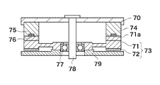
図7は、本実施の形態に係る振動波駆動装置としての回転型超音波モータの構成を示す断面図である。 FIG. 7 is a cross-sectional view showing a configuration of a rotary ultrasonic motor as a vibration wave driving device according to the present embodiment.
図7において、回転型超音波モータは、回転力伝達部材70、弾性体71と圧電素子72から構成される振動子73、ロータ74、弾性部材75、摩擦部材76、軸受77、回転軸78、ベース板79を備えている。
In FIG. 7, the rotary ultrasonic motor includes a rotational
振動子73において、弾性体71は、鉄等の軟磁性材料により円盤状に形成されている。弾性体71の軸方向一方の端部(上面部)には、振動変位拡大のための複数の突起部71aが周方向に沿って配設されている。圧電素子72は、電圧の印加により電気量(電圧)を機械量(振動)に変換する電気−機械エネルギ変換素子であり、円環状に形成されている。弾性体71と圧電素子72を接合することで振動子73を構成している。
In the
ロータ74は、永久磁石により一体化されて構成されると共に円環状に形成されており、振動子73を構成する弾性体71の上部に配置されると共に、回転軸78の周りに回転可能に構成されている。ロータ74の軸方向一方の端部(下面部)には、摩擦接触部としての弾性部材75及び摩擦部材76が周方向に沿って配設されている。摩擦接触部(弾性部材75及び摩擦部材76)は、ロータ74の一部を構成している。
The
ロータ74の一部である摩擦接触部(弾性部材75及び摩擦部材76)は、振動子73を構成する弾性体71の複数の突起部71aと接触している。また、ロータ74の一部である摩擦接触部(弾性部材75及び摩擦部材76)の内周側及び外周側の下面と弾性体71の突起部71aの上面との間(隙間)の距離は、小さく設定されている。
The friction contact portions (the
ロータ24の軸方向他方の端部(上面部)には、円盤状の回転力伝達部材70が係合されている。回転力伝達部材70の中央部には、回転軸78が固定されている。回転軸78の外周側と弾性体71の内周側との間には、軸受77が配設されている。回転軸78は、超音波モータの駆動に伴い軸受77によりガイドされて回転し、超音波モータ外部に出力を伝達する。
A disk-shaped rotational
上記のように、本実施の形態では、ロータ74における振動子73側との対向面の一部に摩擦接触部(弾性部材75及び摩擦部材76)を設けている。また、本実施の形態では、ロータ74の摩擦接触部の内周側及び外周側の下面と弾性体71の突起部71aの上面との間(隙間)の距離は、小さく設定しており、この部分で吸引力を発生する構造となっている。即ち、振動子73とロータ74との間に大きな圧接力(吸引力)を発生させることができる。
As described above, in the present embodiment, the friction contact portion (the
以上説明したように、本実施の形態によれば、モータの小型化及び薄型化を実現しながら、振動子73とロータ74との間の圧接力を十分に確保することが可能となる。また、振動子73とロータ74とを接触させる接触バネ部の設計の自由度を増すことが可能となる。
As described above, according to the present embodiment, it is possible to ensure a sufficient pressure contact force between the
[第5の実施の形態]
本発明の第5の実施の形態は、上記第1の実施の形態に対して図8に示す点において相違する。本実施の形態では、上記第1の実施の形態との相違点を中心に説明し、上記第1の実施の形態と同様(または類似)の部分については説明を省略または簡略化する。
[Fifth Embodiment]
The fifth embodiment of the present invention is different from the first embodiment in the points shown in FIG. In the present embodiment, differences from the first embodiment will be mainly described, and description of the same (or similar) portions as those of the first embodiment will be omitted or simplified.
図8は、本実施の形態に係る振動波駆動装置としてのリニア型超音波モータの構成を示す断面図である。 FIG. 8 is a cross-sectional view showing a configuration of a linear ultrasonic motor as a vibration wave driving device according to the present embodiment.
図8において、リニア型超音波モータは、振動子83、振動子83に励起される振動により摩擦駆動される移動体(被駆動体)87、ヨーク88を備えている。振動子83は、弾性体81、圧電素子82から構成されている。移動体87は、振動子83を構成する弾性体81に対し部分的な隙間を有して接触状態に配置されると共に、永久磁石84、弾性部材85、摩擦部材86から構成されている。移動体87から振動子83に対し前記隙間を介して圧接力を作用させる。
In FIG. 8, the linear ultrasonic motor includes a
振動子83において、弾性体81は、鉄等の軟磁性材料により板状に形成されている。圧電素子82は、電圧の印加により電気量(電圧)を機械量(振動)に変換する電気−機械エネルギ変換素子であり、板状に形成されている。
In the
移動体87において、永久磁石84は、直方体の幅方向角部を含む両側部分を長手方向に沿って切り欠いた駆動方向(移動方向)に細長い形状を有し、直方体部84aと凸部84bとから構成されている。弾性部材85と摩擦部材86は、永久磁石84の凸部84bの両側に積層状態で配置可能な板状に形成されている。
In the moving
尚、移動体87を構成する永久磁石84における振動子対向側とは反対側の磁気損失を低減するため、永久磁石84における振動子対向側とは反対側に直方体形状のヨーク88を接合している。
In order to reduce magnetic loss of the
本実施の形態では、上記第1の実施の形態で示した移動体を構成する永久磁石の着磁パターンを変えることで、振動子と移動体との間で閉磁路を構成する例を示している。 In the present embodiment, an example is shown in which a closed magnetic circuit is configured between the vibrator and the moving body by changing the magnetization pattern of the permanent magnets that constitute the moving body shown in the first embodiment. Yes.
移動体87を構成する永久磁石84の極性は、永久磁石84における振動体83との対向側の全面がS極またはN極に着磁されている(上記第1実施の形態では図示を省略した)。そのため、磁力線は永久磁石84のN極側の面から出て空中を経由して永久磁石84のS極側に戻るようになっている。
As for the polarity of the
以上説明したように、本実施の形態によれば、図示のように、永久磁石84の凸部84bをN極とし、凸部84bの両側の段差部(摩擦部)をS極とするように着磁している。永久磁石84を前記のように着磁することで、磁力線がN極→振動子83→摩擦部→S極という経路を通り超音波モータ内で閉じた磁路を形成することができる。これにより、超音波モータの漏れ磁束等が他の構成要素に影響を及ぼすことなく、効率良く磁力を利用することが可能となる。
As described above, according to the present embodiment, as shown in the figure, the
21、51、61、71、81 弾性体
22、52、62、72、82 圧電素子
23、53、63、73、83 振動子
24、54、64 永久磁石
25、55、65、75、85 弾性部材
26、56、66、76、86 摩擦部材
27、57、67、87 移動体
74 ロータ
21, 51, 61, 71, 81
Claims (5)
前記振動子を構成する前記弾性体に対し部分的な隙間を有して接触され、前記振動子に励起される振動により発生する摩擦駆動力によって駆動される被駆動体と、
前記振動子と前記被駆動体との間に圧接力を発生させる加圧手段とを備え、
前記電気−機械エネルギ変換素子と前記弾性体は、板状に形成され、
前記被駆動体は、駆動方向に長い形状に形成され、
前記加圧手段を前記圧接力としての磁力を発生させる永久磁石から構成すると共に、前記永久磁石を前記被駆動体と一体的に形成し、
前記振動子と前記被駆動体とが対向する部分に、前記振動子と前記被駆動体とを接触させる摩擦接触部と前記永久磁石による圧接力発生部とを分離して配置し、
前記摩擦接触部は、前記被駆動体側又は前記振動子側のいずれかに配置され、
前記摩擦接触部は、バネ性を有する弾性部材と耐磨耗性を有する摩擦部材とから構成され、
前記振動子の前記弾性体と前記被駆動体との間に設ける前記隙間の距離を、前記振動子と前記被駆動体との間に配置される前記摩擦接触部の厚さより小さく構成したことを特徴とする振動波駆動装置。 A vibrator configured by joining an electro-mechanical energy conversion element that converts an electrical quantity into a vibration as a mechanical quantity and an elastic body made of a soft magnetic material;
A driven body that is brought into contact with the elastic body constituting the vibrator with a partial gap and is driven by a frictional driving force generated by vibration excited by the vibrator;
Pressurizing means for generating a pressing force between the vibrator and the driven body,
The electro-mechanical energy conversion element and the elastic body are formed in a plate shape,
The driven body is formed in a long shape in the driving direction,
The pressurizing means is composed of a permanent magnet that generates a magnetic force as the pressure contact force, and the permanent magnet is formed integrally with the driven body,
A friction contact portion for bringing the vibrator and the driven body into contact with each other and a portion where the vibrator and the driven body are opposed to each other and a pressure contact force generating portion by the permanent magnet are separately disposed,
The friction contact portion is disposed on either the driven body side or the vibrator side,
The friction contact portion is composed of an elastic member having spring properties and a friction member having wear resistance,
The distance of the gap provided between the elastic body of the vibrator and the driven body is configured to be smaller than the thickness of the friction contact portion disposed between the vibrator and the driven body. A characteristic vibration wave drive device.
前記弾性体と前記永久磁石との間の前記隙間を前記凸部の高さ方向の寸法に比較して小さく設定すると共に、前記隙間を介して前記圧接力を作用させることを特徴とする請求項1記載の振動波駆動装置。 A section perpendicular to the drive direction of the driven body in the permanent magnet is formed in a convex shape, and the friction contact portions are disposed on both sides of the convex portion formed in the convex section.
The gap between the elastic body and the permanent magnet is set to be smaller than the dimension in the height direction of the convex portion, and the pressure contact force is applied through the gap. The vibration wave drive device according to 1.
前記弾性体と前記永久磁石との間の前記隙間を前記凹部の深さ方向の寸法に比較して小さく設定すると共に、前記隙間を介して前記圧接力を作用させることを特徴とする請求項1記載の振動波駆動装置。 A section perpendicular to the driving direction of the driven body in the permanent magnet is formed in a concave shape, and the friction contact portion is disposed inside a concave portion formed in the concave section.
2. The clearance between the elastic body and the permanent magnet is set to be smaller than the dimension in the depth direction of the recess, and the pressing force is applied through the clearance. The vibration wave driving device described.
Priority Applications (1)
| Application Number | Priority Date | Filing Date | Title |
|---|---|---|---|
| JP2007169142A JP5349768B2 (en) | 2007-06-27 | 2007-06-27 | Vibration wave drive |
Applications Claiming Priority (1)
| Application Number | Priority Date | Filing Date | Title |
|---|---|---|---|
| JP2007169142A JP5349768B2 (en) | 2007-06-27 | 2007-06-27 | Vibration wave drive |
Publications (3)
| Publication Number | Publication Date |
|---|---|
| JP2009011058A JP2009011058A (en) | 2009-01-15 |
| JP2009011058A5 JP2009011058A5 (en) | 2010-07-01 |
| JP5349768B2 true JP5349768B2 (en) | 2013-11-20 |
Family
ID=40325567
Family Applications (1)
| Application Number | Title | Priority Date | Filing Date |
|---|---|---|---|
| JP2007169142A Active JP5349768B2 (en) | 2007-06-27 | 2007-06-27 | Vibration wave drive |
Country Status (1)
| Country | Link |
|---|---|
| JP (1) | JP5349768B2 (en) |
Cited By (1)
| Publication number | Priority date | Publication date | Assignee | Title |
|---|---|---|---|---|
| US10498261B2 (en) | 2016-01-14 | 2019-12-03 | Canon Kabushiki Kaisha | Vibration-type actuator that moves vibrating body and driven body relatively to each other, and electronic apparatus |
Families Citing this family (1)
| Publication number | Priority date | Publication date | Assignee | Title |
|---|---|---|---|---|
| JP6576214B2 (en) | 2015-11-06 | 2019-09-18 | キヤノン株式会社 | Vibration type actuator, lens barrel, imaging device and stage device |
Family Cites Families (5)
| Publication number | Priority date | Publication date | Assignee | Title |
|---|---|---|---|---|
| JPS6356176A (en) * | 1986-08-22 | 1988-03-10 | Nippon Denso Co Ltd | Ultrasonic motor |
| JPS63277478A (en) * | 1987-04-10 | 1988-11-15 | Matsushita Electric Ind Co Ltd | Ultrasonic motor |
| JPH0222094U (en) * | 1988-07-26 | 1990-02-14 | ||
| JPH0866061A (en) * | 1994-08-19 | 1996-03-08 | Mitsui Petrochem Ind Ltd | Ultrasonic motor |
| JP4072518B2 (en) * | 2004-06-09 | 2008-04-09 | キヤノン株式会社 | Vibration wave drive |
-
2007
- 2007-06-27 JP JP2007169142A patent/JP5349768B2/en active Active
Cited By (1)
| Publication number | Priority date | Publication date | Assignee | Title |
|---|---|---|---|---|
| US10498261B2 (en) | 2016-01-14 | 2019-12-03 | Canon Kabushiki Kaisha | Vibration-type actuator that moves vibrating body and driven body relatively to each other, and electronic apparatus |
Also Published As
| Publication number | Publication date |
|---|---|
| JP2009011058A (en) | 2009-01-15 |
Similar Documents
| Publication | Publication Date | Title |
|---|---|---|
| KR101201261B1 (en) | Vibration wave driving device | |
| JP4756916B2 (en) | Vibration wave motor | |
| JP5641800B2 (en) | Vibration type driving device | |
| JP2012016107A (en) | Vibration-type drive unit | |
| JP5656429B2 (en) | Vibration wave drive | |
| JP5349768B2 (en) | Vibration wave drive | |
| JP4881064B2 (en) | Vibration type driving device | |
| JP3566711B2 (en) | Vibration wave drive | |
| JP2008048557A (en) | Piezoelectric actuator | |
| JP3444502B2 (en) | Ultrasonic linear motor | |
| JP4612798B2 (en) | Power transmission mechanism | |
| KR100661311B1 (en) | Piezoelectric ultrasonic motor | |
| JP4979017B2 (en) | Ultrasonic motor and ultrasonic vibrator used therefor | |
| JPH02311184A (en) | Ultrasonic motor | |
| JP4316350B2 (en) | Ultrasonic motor and electronic device with ultrasonic motor | |
| JP2004297872A (en) | Vibration actuator and its manufacturing method | |
| JPH07178370A (en) | Vibrator and vibrating actuator | |
| KR20030013927A (en) | Half-bimorph vibrator of linear ultrasonic motor | |
| JPS61173683A (en) | Supersonic drive motor | |
| JPH08223947A (en) | Ultrasonic motor | |
| JP2000245175A (en) | Vibration actuator | |
| JPS62107688A (en) | Small-sized actuator | |
| JP2011259557A (en) | Drive mechanism of mobile by vibration type drive unit | |
| JP2009033791A (en) | Ultrasonic motor | |
| JP2005020839A (en) | Micro motor |
Legal Events
| Date | Code | Title | Description |
|---|---|---|---|
| A521 | Written amendment |
Free format text: JAPANESE INTERMEDIATE CODE: A523 Effective date: 20100519 |
|
| A621 | Written request for application examination |
Free format text: JAPANESE INTERMEDIATE CODE: A621 Effective date: 20100519 |
|
| A977 | Report on retrieval |
Free format text: JAPANESE INTERMEDIATE CODE: A971007 Effective date: 20120425 |
|
| A131 | Notification of reasons for refusal |
Free format text: JAPANESE INTERMEDIATE CODE: A131 Effective date: 20120508 |
|
| A521 | Written amendment |
Free format text: JAPANESE INTERMEDIATE CODE: A523 Effective date: 20120703 |
|
| A131 | Notification of reasons for refusal |
Free format text: JAPANESE INTERMEDIATE CODE: A131 Effective date: 20121225 |
|
| A521 | Written amendment |
Free format text: JAPANESE INTERMEDIATE CODE: A523 Effective date: 20130221 |
|
| TRDD | Decision of grant or rejection written | ||
| A01 | Written decision to grant a patent or to grant a registration (utility model) |
Free format text: JAPANESE INTERMEDIATE CODE: A01 Effective date: 20130723 |
|
| A61 | First payment of annual fees (during grant procedure) |
Free format text: JAPANESE INTERMEDIATE CODE: A61 Effective date: 20130821 |
|
| R151 | Written notification of patent or utility model registration |
Ref document number: 5349768 Country of ref document: JP Free format text: JAPANESE INTERMEDIATE CODE: R151 |