JP4612798B2 - Power transmission mechanism - Google Patents
Power transmission mechanism Download PDFInfo
- Publication number
- JP4612798B2 JP4612798B2 JP2004076393A JP2004076393A JP4612798B2 JP 4612798 B2 JP4612798 B2 JP 4612798B2 JP 2004076393 A JP2004076393 A JP 2004076393A JP 2004076393 A JP2004076393 A JP 2004076393A JP 4612798 B2 JP4612798 B2 JP 4612798B2
- Authority
- JP
- Japan
- Prior art keywords
- power transmission
- voltage
- transmission mechanism
- vibrator
- power
- Prior art date
- Legal status (The legal status is an assumption and is not a legal conclusion. Google has not performed a legal analysis and makes no representation as to the accuracy of the status listed.)
- Expired - Fee Related
Links
Images


Classifications
-
- F—MECHANICAL ENGINEERING; LIGHTING; HEATING; WEAPONS; BLASTING
- F16—ENGINEERING ELEMENTS AND UNITS; GENERAL MEASURES FOR PRODUCING AND MAINTAINING EFFECTIVE FUNCTIONING OF MACHINES OR INSTALLATIONS; THERMAL INSULATION IN GENERAL
- F16D—COUPLINGS FOR TRANSMITTING ROTATION; CLUTCHES; BRAKES
- F16D28/00—Electrically-actuated clutches
Landscapes
- Engineering & Computer Science (AREA)
- General Engineering & Computer Science (AREA)
- Physics & Mathematics (AREA)
- Electromagnetism (AREA)
- Mechanical Engineering (AREA)
- General Electrical Machinery Utilizing Piezoelectricity, Electrostriction Or Magnetostriction (AREA)
Description
駆動側から被駆動側への動力の伝達状態を切り換える動力伝達機構に関する。 Concerning the driving side power transmission mechanism for switching the transmitting state of the power to the driven side.
モータ等の動力発生源による動力を被駆動体へ伝達するクラッチ等の動力伝達機構がある。 There is a power transmission mechanism such as a clutch that transmits power from a power generation source such as a motor to a driven body.
例えば、特許文献1には、動力発生源の回転軸にフライホイールが固定されるとともに、被駆動体の回転軸には摩擦ディスクを嵌合したセンターハブが固定され、周状に配置されたスプリングによって摩擦ディスクをフライホイールに圧接させることによって、フライホイールと摩擦ディスクとの間の摩擦力を用いて動力発生源による回転動力を被駆動体に伝達するものが開示されている。スプリングはカバーに支持され、支持部よりも外周側でプレッシャープレートを介して摩擦ディスクを加圧している。スプリングの支持部よりも内周側をフライホイール側に移動させると、スプリングの支持部よりも外周側がフライホイールから離れ、摩擦ディスクとフライホイールとの圧接が解除されて回転動力の伝達を中断する。
For example, in
また、回転動力の伝達、非伝達の切り換えを電磁力によって行う電磁クラッチがある。例えば、特許文献2には、動力発生源の出力部とロータがベルトを介して連結されるとともに、被駆動体の回転軸にはアーマチュアと一体に回転するハブが固定され、断面がコ字形のロータの内部に配置されたステータを励磁することによってアーマチュアとロータを吸着させ、動力発生源による回転動力を被駆動体に伝達するものが開示されている。ステータの励磁を解除させると、電磁力が消滅して板バネ部材のバネ力によりアーマチュアとロータが離れ、回転動力の伝達を中断する。
しかしながら上記の動力伝達機構は部品点数が多く、構成も複雑で小型化には限界がある。 However, the power transmission mechanism described above has a large number of parts, a complicated structure, and there is a limit to downsizing.
特に、特許文献1のような動力伝達機構はクラッチを切るためにスプリングの内周側をフライホイール側に移動させるための機械的構成が必要となり、より複雑、大型化となる問題がある。
In particular, the power transmission mechanism as disclosed in
また、特許文献2のような動力伝達機構はステータの内部に収納された電磁コイルに通電することで容易にステータを励磁してクラッチを繋ぐことができるが、電磁コイルの励磁による吸引では応答性が悪い、動力伝達時に負荷に負けない吸着力が必要とされるため電力の消費量が大きいなどの問題がある。 In addition, the power transmission mechanism as in Patent Document 2 can easily excite the stator and connect the clutch by energizing the electromagnetic coil housed in the stator. However, there is a problem that power consumption is large because an attractive force that is not defeated by the load is required during power transmission.
本発明は上記の課題を鑑みてなされたものであり、動力の伝達状態の切り換えを電気的に制御できる動力伝達機構および動力伝達方法であって、小型化、応答性の向上を目的とするものである。 The present invention has been made in view of the above problems, and is a power transmission mechanism and a power transmission method capable of electrically controlling switching of a power transmission state, and aims to reduce the size and improve responsiveness. It is.
上記課題を解決するために本発明は、第一の部材と、第二の部材と、を有し、前記第一の部材と、前記第二の部材と、が加圧されて接触し、前記第一の部材または前記第二の部材のいずれか一方の部材が動力発生源から受けた回転トルクを他方の部材に伝達する動力伝達機構であって、
前記第一の部材と前記第二の部材とを圧接させるための加圧手段と、
前記第一の部材に設けられた電気機械エネルギー変換素子に交流電圧を供給する制御手段と、を備え、
前記電気機械エネルギー変換素子に交流電圧を供給していないときには前記動力発生源から受けた回転トルクにより前記第1の部材と第2の部材とが一体に回転し、
前記制御手段は、前記交流電圧の電圧値または周波数を制御することで、前記第一の部材に生じる面外振動の振動振幅を制御し、前記加圧手段の加圧力に抗して前記第一の部材と前記第二の部材の間に超音波浮揚現象による浮揚力を発生させるものであって、前記交流電圧の電圧値または周波数を変化させることで、前記第一の部材と前記第二の部材の間で伝達される回転トルクを変化させることを特徴とするものである。
また本発明は、第一の部材と、第二の部材と、を有し、前記第一の部材と、前記第二の部材と、が加圧されて接触し、前記第一の部材または前記第二の部材のいずれか一方の部材が動力発生源から受けた動力を他方の部材に伝達する動力伝達機構であって、
前記第一の部材と前記第二の部材とを圧接させるための加圧手段と、
前記第一の部材に設けられた電気機械エネルギー変換素子に交流電圧を供給する制御手段と、を備え、前記制御手段は、前記交流電圧の電圧値または周波数を制御することで、前記第一の部材に生じる面外振動の振動振幅を制御し、前記加圧手段の加圧力に抗して前記第一の部材と前記第二の部材の間に超音波浮揚現象による浮揚力を発生させるものであって、前記交流電圧の電圧値または周波数を変化させることで、前記第一の部材と前記第二の部材の間で伝達される動力を変化させ、前記第1の部材または前記第2の部材の一方は片面に長手方向に延び、かつ、根元がくびれた凸部を有し、他方の部材は前記凸部と嵌合する凹部を有することを特徴とする動力伝達機構。
また本発明は、第一の部材と、第二の部材と、を有し、前記第一の部材と、前記第二の部材と、が加圧されて接触し、前記第一の部材または前記第二の部材のいずれか一方の部材が動力発生源から受けた動力を他方の部材に伝達する動力伝達機構であって、
前記第一の部材と前記第二の部材とを圧接させるための加圧手段と、
前記第一の部材に設けられた電気機械エネルギー変換素子に交流電圧を供給する制御手段と、を備え、
前記第一の部材または前記第二の部材のいずれか一方の部材が支持板を介してハウジングに固定され、
他方の部材が回転軸と一体に回転可能に構成されており、
前記制御手段は、前記交流電圧の電圧値または周波数を制御することで、前記第一の部材に生じる面外振動の振動振幅を制御し、前記加圧手段の加圧力に抗して前記第一の部材と前記第二の部材の間に超音波浮揚現象による浮揚力を発生させるものであって、前記交流電圧の電圧値または周波数を変化させることで、前記第一の部材と前記第二の部材の間で伝達される動力を変化させることを特徴とするものである。
The present invention in order to solve the above problems, a first member, a second member having a said a first member, said second member, but in contact with pressurized, the A power transmission mechanism for transmitting rotational torque received from a power generation source by either one of the first member or the second member to the other member;
And pressurizing means for pressing the said second member and said first member,
And control means for supplying an AC voltage to the electro-mechanical energy conversion element provided on said first member,
When the AC voltage is not supplied to the electromechanical energy conversion element, the first member and the second member are integrally rotated by the rotational torque received from the power generation source,
The control means controls a vibration amplitude of out-of-plane vibration generated in the first member by controlling a voltage value or a frequency of the AC voltage, and resists the pressurizing force of the pressurizing means. It is one that generates the levitation force by ultrasonic levitation between the member and the second member, by varying the voltage value or frequency of the AC voltage, wherein the pre-Symbol first member first it is characterized in that to change the rotational torque transmitted between the second member.
Moreover, this invention has a 1st member and a 2nd member, and said 1st member and said 2nd member are pressurized and contacted, said 1st member or said A power transmission mechanism for transmitting power received from a power generation source by any one of the second members to the other member;
Pressurizing means for press-contacting the first member and the second member;
Control means for supplying an AC voltage to the electromechanical energy conversion element provided in the first member, and the control means controls the voltage value or frequency of the AC voltage, thereby controlling the first voltage. Controls the vibration amplitude of out-of-plane vibration generated in the member, and generates a levitation force due to an ultrasonic levitation phenomenon between the first member and the second member against the pressing force of the pressurizing means. The power transmitted between the first member and the second member is changed by changing the voltage value or frequency of the AC voltage, and the first member or the second member is changed. One of the power transmission mechanisms has a convex portion extending in the longitudinal direction on one side and having a constricted base, and the other member has a concave portion that fits into the convex portion .
Moreover, this invention has a 1st member and a 2nd member, and said 1st member and said 2nd member are pressurized and contacted, said 1st member or said A power transmission mechanism for transmitting power received from a power generation source by any one of the second members to the other member;
Pressurizing means for press-contacting the first member and the second member;
Control means for supplying an alternating voltage to the electromechanical energy conversion element provided in the first member,
Either one of the first member and the second member is fixed to the housing via a support plate,
The other member is configured to be rotatable integrally with the rotation shaft,
The control means controls a vibration amplitude of out-of-plane vibration generated in the first member by controlling a voltage value or a frequency of the AC voltage, and resists the pressurizing force of the pressurizing means. Generating a levitation force due to an ultrasonic levitation phenomenon between the first member and the second member, and changing the voltage value or frequency of the AC voltage to change the first member and the second member. The power transmitted between the members is changed.
本発明によれば、振動子と移動体を加圧して接触させ、振動子に振動を励起して移動体に加圧力に抗する浮揚力を発生させることで、振動子と移動体の間の動力伝達効率を容易に制御できるとともに、小型化、応答性に優れた動力伝達機構を提供することができる。 According to the present invention, the vibrator and the moving body are pressurized and brought into contact, and the vibrator is excited to generate a levitation force that resists the applied pressure. It is possible to provide a power transmission mechanism that can easily control power transmission efficiency and that is excellent in downsizing and responsiveness.
以下、添付図面を参照して本発明を実施するための最良の形態を詳細に説明する。 The best mode for carrying out the present invention will be described below in detail with reference to the accompanying drawings.
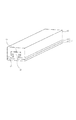
図1(a)に本発明の実施例1に係る動力伝達機構の断面図、図1(b)に斜視図を示す。
FIG. 1A is a cross-sectional view of a power transmission mechanism according to
10は動力伝達機構である。1はモータやエンジン等の動力発生源の回転トルクを受ける振動子、2は被駆動体に接続され、自らが振動子1から回転トルクを受けることで被駆動体を回転させる移動体であり、両部材間の摩擦力を得るためにコイルバネ9等の弾性部材の弾性力によって移動体2に均等な垂直荷重を与え、振動子1と移動体2を圧接させている。振動子1が被駆動体に接続され、移動体2が動力発生源に接続されていても構わない。振動子1は片面の中央に凸部5を有する円板形状の黄銅である振動体4と、円板形状の電気機械エネルギー変換素子である圧電素子3とで構成され、圧電素子3は振動体4の凸部5が設けられた面の反対側となる面にエポキシ樹脂等によって固着されている。移動体2は中心部に振動体4の凸部5と嵌合する凹部6を設けた円板形状の鉄鋼材料で構成されている。振動体4と移動体2の接触面の一方あるいは両方は、摩耗防止のためのメッキ処理、窒化処理、ラップ加工、ポリッシュ加工のいずれか、もしくは複数が施されている。
移動体2の凹部6の径は振動体4の凸部5の径よりも僅かに大きく構成され、コイルバネ9の加圧力によって振動体4の凸部5と移動体2の凹部6は常に嵌合されているため、振動子1と移動体2は回転方向への相対的な移動は許容されるが、径方向への相対的な移動はわずかに許容されるのみである。
The diameter of the
振動子1の圧電素子3にはフレキシブル基板8が固着され、不図示の駆動制御回路より圧電素子3の分極領域へ交流電圧が供給される。実施例1では圧電素子3に交流電圧を供給すると、振動子1には、振動子1と同心円の節を1つ有する面外曲げ振動が発生する。図2は振動子1を中心を通る面で分割した断面図であり、ある瞬間での面外曲げ振動を模式的に示している。図2の白抜き四角が圧電素子3に交流電圧を供給していない状態での振動子1を示しており、径の中間付近を節として振動子1が面外曲げ振動を発生しているのがわかる。実施例1の振動子1の図2に示す面外曲げ振動における固有振動数はおおよそ20.35kHzであり、この面外曲げ振動は定在波である。
A flexible substrate 8 is fixed to the piezoelectric element 3 of the
ここで本発明の動力伝達機構10の動作原理を説明する。
Here, the operation principle of the
本発明の動力伝達機構は、超音波の放射圧による超音波浮揚現象を利用したものである。放射圧とは、音場の中に置かれた物体に作用する一種の時間平均的な圧力であり、変動圧力の直流分といえる。この放射圧は物体に吸収され音波の経路に沿って放射圧の減少が起こり、微小区間の直流圧力差によって流体中に流れが生じる。これらの現象を利用すると音場の中に置かれた物体に浮揚力を発生させ、この物体を非接触で空間の一定の位置に浮揚したまま保持することができる。この現象を超音波浮揚現象と呼ぶ。 The power transmission mechanism of the present invention utilizes an ultrasonic levitation phenomenon caused by ultrasonic radiation pressure. Radiation pressure is a kind of time-averaged pressure acting on an object placed in a sound field, and can be said to be a direct current component of fluctuating pressure. This radiation pressure is absorbed by the object, and the radiation pressure decreases along the sound wave path, and a flow is generated in the fluid due to the direct-current pressure difference in the minute section. By utilizing these phenomena, a levitation force is generated on an object placed in the sound field, and this object can be held in a fixed position in space without contact. This phenomenon is called an ultrasonic levitation phenomenon.
超音波浮揚現象によって得られる浮揚力は、振動振幅の2乗に比例することが知られている。圧電素子3に振動子1の固有振動数の近傍となる周波数の交流電圧を供給し、振動子1の振動状態を共振に近づけ振動子1の移動体2との接触面7に振動変位を励起する。このとき接触面7には強力な超音波の放射圧が発生し、コイルバネ9によって生じる振動子1と移動体2の加圧力に抗して、移動体2に浮揚力が生じ、振動子1と移動体2との間の摩擦力は減少する。
It is known that the levitation force obtained by the ultrasonic levitation phenomenon is proportional to the square of the vibration amplitude. An AC voltage having a frequency close to the natural frequency of the
振動子1の圧電素子3に交流電圧を供給していないときは、振動子1に発生駆動源から回転トルクを与えると、振動子1と移動体2の間の摩擦力によって振動子1と移動体2が一体に回転し、回転トルクが振動子1から移動体2に伝達されて被駆動体を回転させる。
When an AC voltage is not supplied to the piezoelectric element 3 of the
一方、振動子1の圧電素子3に上記の固有振動数よりも高い周波数の交流電圧を供給し、交流電圧の周波数を徐々に下げて固有振動数に近づけていくと、徐々に振動子1の接触面7に生じる振動振幅が大きくなり、先に述べた超音波浮揚が生じる。交流電圧の周波数を更に固有振動数に近づけて振動子1の振動振幅を大きくし、移動体2に生じる浮揚力が不図示のコイルバネによる加圧力よりも大きくなると、振動子1の接触面と移動体2は非接触状態となり(振動子1の凸部5と移動体2の凹部6は嵌合している)、振動子1の接触面7と移動体2との間の静摩擦力および動摩擦力はゼロとなる。この状態では振動子1を回転させても振動子1の回転トルクは移動体2に伝達しなくなる。
On the other hand, when an alternating voltage having a frequency higher than the natural frequency is supplied to the piezoelectric element 3 of the
このように実施例1に係る動力伝達機構10は、トルク伝達の有無の切り換えを行う機能を有するクラッチを構成している。この動力伝達機構10は圧電素子3と弾性体4からなる振動子1、移動体2、および、これらを圧接させるコイルバネ9等の弾性部材で構成できるため、部品点数の削減及び形状の簡素化が可能となり、小型化に適している。また、振動子1と移動体2の接触面を大きく取ることができるため、トルクを伝達する際に係る負荷に耐え得るだけの十分な摩擦力も得られる。
As described above, the
移動体2に生じる浮揚力がコイルバネ9による加圧力より小さい場合であっても、この浮揚力によって振動子1が移動体2から受ける荷重は減少し、振動体1と移動体2との間の摩擦力は減少する。したがって、圧電素子3に供給する交流電圧の電圧値または周波数を変化させて振動子1の接触面7に生じる振動振幅を変化させ移動体2に生じる浮揚力を変化させることで、振動子1と移動体2との間の摩擦力を連続的に制御することも可能である。振動子1に発生させる振動は、従来の電磁コイルを用いた場合と比較して、圧電素子に供給される交流電圧に対する応答性が格段に優れている。
Even when the levitation force generated in the moving body 2 is smaller than the pressure applied by the
なお、振動子1に供給される振動の周波数は20kHz以上であることが好ましい。可聴域外となり、静粛な動力伝達機構とすることができるからである。振動子1が板状に形成されているのは、面外曲げ振動に対する振動子1の動剛性を低くして共振周波数を下げ、振動振幅を大きくするためである。なお、振動子1に励起された振動の周波数が固有振動数と一致したときに振動子1の振動振幅が最も大きくなり、超音波浮揚現象によって得られる浮揚力も最も大きくなる。この得られる浮揚力の大きさに応じて振動子1と移動体2との間の加圧力を設定すればよい。なお、加圧力が大きいほど圧電素子3に交流電圧を供給しないときの振動子1と移動体2の間の摩擦力が大きくなることは言うまでもないであろう。
Note that the frequency of vibration supplied to the
振動子1を円形としたのは、振動子1と移動体2が相対的に回転しても振動子1と移動体2の接触部の面積が変化しないようにさせるためであり、超音波浮揚現象による浮揚力を一定に保って挙動の安定したクラッチを構成することが可能となる。
The reason why the
また、図2に示すように振動子1に円状に節を有する振動を励起することで、振動子1に励起される振動形態が周方向で均一となり、超音波浮揚現象による浮揚力も周方向で均一とすることが可能となる。これもクラッチの挙動を安定させるために効果的である。
Further, as shown in FIG. 2, by exciting vibration having a circular node in the
このように交番信号(交流電圧)が供給されることで表面に振動を励起する振動子と、移動体とを有し、振動が励起される振動子の面に移動体を加圧して接触させ、これら振動子と移動体とが接触が解除される方向、例えば、振動が励起される面に対して垂直な方向に加圧力に反して相対的に移動可能となるように構成することで、従来よりも非常に小型なクラッチ等の動力伝達機構を構成することができる。 By supplying an alternating signal (alternating voltage) in this way, a vibrator that excites vibration on the surface and a moving body are provided, and the moving body is pressed and brought into contact with the surface of the vibrator that is excited by vibration. By configuring the vibrator and the moving body so as to be relatively movable against the applied pressure in the direction in which the contact is released, for example, in the direction perpendicular to the surface where the vibration is excited, A power transmission mechanism such as a clutch that is much smaller than conventional ones can be configured.
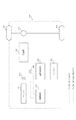
次にこの動力伝達機構10を用いた装置を、例をあげて説明する。図7に実施例1に係る動力伝達機構を用いたハイブリッド車を示す。
Next, an apparatus using the
ハイブリッド車には、エンジンで発電機を駆動し、発電機した電力によって駆動されるモータが駆動輪を駆動するタイプのもの、モータの駆動力とエンジンの駆動力を切換えて駆動輪を駆動するタイプのもの、あるいは、エンジンの動力を分割し、一方で直接駆動輪を駆動して他方で発電を起こしてモータを駆動させるものなど、様々なタイプが提案されている。この中のモータの駆動力とエンジンの駆動力を切換えて駆動輪を駆動するパラレルタイプのハイブリッド車を例にあげて説明する。 Hybrid vehicles have a type in which a generator is driven by an engine, and a motor driven by the power generated by the generator drives a drive wheel. A type in which a drive wheel is driven by switching between the motor driving force and the engine driving force. Various types have been proposed, such as those that divide the motive power of the engine, and that directly drive the driving wheel and generate electric power on the other side to drive the motor. A parallel type hybrid vehicle that drives the driving wheels by switching the driving force of the motor and the driving force of the engine will be described as an example.
100はハイブリッド車の本体である。101はエンジンであり、エンジンの出力軸には第1のクラッチ10Aが連結されている。このクラッチ10Aからの入力軸が変速機102に連結され、変速機102の出力軸がディファレンシャルギヤ103に接続される。このディファレンシャルギヤ103の出力は車軸を介して駆動輪104に伝達される。変速機102の入力側には第2のクラッチ10Bを介して、変速機102から見てエンジンと並列になるように電動発電機105が連結されている。この電動発電機105はバッテリーの電力を消費して電動機として作動したり、バッテリーへ電力を蓄積する発電機として作動したりする。ここで、クラッチ10A、10Bは上述の動力伝達機構10と同じ構成となっており、制御回路107がクラッチ10A、10Bに交流電圧を供給することによって、これらの入力側と出力側の連結を選択的に切断することができる。
制御回路107は、エンジン効率の低い発進時には第1のクラッチ10A、第2のクラッチ10Bを接続状態として、所定の速度に達したら第2のクラッチ10Bに交流電圧を供給して超音波浮揚状態を発生させて切断状態とし、エンジン101の駆動力のみを変速機102に伝達させる。また、制御回路107は停止時には第1のクラッチ10Aに交流電圧を供給してこれを切断状態とし、変速機の入力軸の回転を入力エネルギーとして電動発電機105がバッテリーへの蓄電を行う。
The
この構成によれば、上記の動力伝達機構を用いてエンジンの出力と、電動発電機の入出力の選択的な切断状態を制御することが可能なハイブリッド車を構成することができる。 According to this configuration, it is possible to configure a hybrid vehicle capable of controlling the engine output and the selective disconnection state of the input / output of the motor generator using the power transmission mechanism.
続いて図8に実施例1に係る動力伝達機構を用いたロボットアームを示す。201は人間の腕にあたる支持部、202〜207は指部であり、それぞれの指部は一方の端部あるいは両方の端部に動力伝達機構10C〜10Fのいずれかが結合されている。動力伝達機構10C〜10Fはそのステータが隣接する一方の指部に結合され、移動体が隣接する他方の指部に結合されている。また、動力伝達機構10C〜10Fのステータには同一の駆動源208が連結されており、駆動源208を駆動することで動力伝達機構10C〜10Fのステータには指を開く方向、あるいは閉じる方向のいずれかの動力が伝達される。209は動力伝達機構10C〜10Fの制御装置であり、動力伝達機構10C〜10Fのそれぞれに独立して交流電圧を供給するものである。
Next, FIG. 8 shows a robot arm using the power transmission mechanism according to the first embodiment.
指を開く際、あるいは、閉じる際に、動力伝達機構10C〜10Fに互いに異なる周波数や振幅の交流電圧を供給することで、これら動力伝達機構10C〜10Fの動力の伝達効率に差が生じ、それぞれの動力伝達機構に異なる動作をさせることが可能となる。したがって、同一の駆動源を用いるにもかかわらず、掴もうとする物体の形状に沿って指を曲げたり、握力を調整したりすることが可能となる。 When the fingers are opened or closed, by supplying alternating voltages having different frequencies and amplitudes to the power transmission mechanisms 10C to 10F, a difference occurs in the power transmission efficiency of these power transmission mechanisms 10C to 10F. It is possible to cause the power transmission mechanism to perform different operations. Therefore, it is possible to bend the finger along the shape of the object to be grasped or to adjust the gripping force despite using the same drive source.
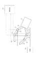
図3に本発明の実施例2に係る動力伝達機構の斜視図を示す。 FIG. 3 is a perspective view of a power transmission mechanism according to the second embodiment of the present invention.
11は振動子、12は移動体であり、両部材間の摩擦力を得るために不図示の渦巻きバネ等の弾性部材によって移動体12に垂直荷重を与え振動子11と圧接させている。振動子11は片面の中央に長手方向に延び、かつ、根元がくびれた凸部15を有するステンレス矩形板形状のステンレスである振動体14と、矩形板形状の圧電素子13とで構成され、圧電素子13は振動体14の凸部15が設けられた面の反対側となる面にろう付けにより固着されている。移動体12は中央に振動体14の凸部15と嵌合する長手方向に延びた凹部16を設けた樹脂で構成されている。移動体14はその先端部が、振動体14の凸部15を除いた平板で構成された面(この面を接触面17とする)と接触している。振動子11の圧電素子13に実施例1と同様にフレキシブル基板を介して不図示の駆動制御回路から交流電圧を供給すると、振動子11の接触面17には面外曲げ振動が励起される。
この凹部16の先端は幅が狭くなっており、この先端が振動体14の凸部15の根元のくびれに入り込むよう形成されている。凹部16の根元(底)の幅は凸部15の先端の幅よりも僅かに大きく構成され、振動子11と移動体12は長手方向に相対的にスライドすることは許容されているが、これに垂直な方向に相対的にスライドすることはわずかに許容されているのみである。もし振動子11と移動体12が外部から接触面17に垂直な方向の大きな力を受けたとしても、移動体12の凹部16の先端部の幅は振動体14の凸部15の先端部15の幅よりも狭いため外れてしまうことがない。また、振動体14の凸部15を設けることで、凸部15の質量効果により振動子11の固有振動数を下げ、接触面17に励起する面外振動の振幅を大きくすることができ、伝達可能な駆動力の範囲を広くすることが可能となる。
The tip of the
また、振動体14の凸部15の幅広の先端部と、移動体16の凹部の幅狭の先端部との間には隙間が設けられ、振動子11と移動体16とは互いに離れる方向に移動することが許容されている。当然に、この移動が許容される量とは振動子11に励起される振動振幅よりも十分に大きく構成される。
In addition, a gap is provided between the wide tip portion of the
振動子11の接触面17に面外振動を励起させて移動体12に浮揚力を与えることで、振動子11と移動体12が非接触状態となりこの間の摩擦力はゼロとなる。この状態では振動子11に長手方向へ移動する駆動力を与えたとしても、移動体12にはその駆動力が伝達されない。このように実施例2では直動型のクラッチ機構を構成することができる。
Exciting out-of-plane vibration to the
図4に本発明の実施例3に係る動力伝達機構の斜視図を示す。 FIG. 4 is a perspective view of a power transmission mechanism according to Embodiment 3 of the present invention.
21は振動子、22は移動体、23は圧電素子、24は圧電素子23が固定された振動体であり、圧電素子23と振動体24により振動子21を構成している。25は振動体24の片面に設けられた凸部、26は移動体21に設けられ、振動体24の凸部25と嵌合する凹部である。
21 is a vibrator, 22 is a moving body, 23 is a piezoelectric element, 24 is a vibrating body to which the piezoelectric element 23 is fixed, and the piezoelectric element 23 and the vibrating body 24 constitute the
図4に示す動力伝達機構は、移動体24と接触するための振動体24の接触面27の位置のみが図3の動力伝達機構と異なっている。この動力伝達機構では、振動体24の凸部25の先端部を接触面27としている。振動子21に振動を励起したとき、凸部25の先端部自体の変形はほとんど生じないため、凸部25の先端部の変位分布は均一となり、接触面27から均一な浮揚力が得られ、挙動の安定した動力伝達機構を構成することができる。
The power transmission mechanism shown in FIG. 4 is different from the power transmission mechanism of FIG. 3 only in the position of the contact surface 27 of the vibrating body 24 for contacting the moving body 24. In this power transmission mechanism, the tip of the
図5に本発明の実施例4に係る動力伝達機構を用いた作動装置の断面図を示す。 FIG. 5 shows a cross-sectional view of an operating device using a power transmission mechanism according to Embodiment 4 of the present invention.
31はベルトを介して動力発生源の回転トルクを受ける出力部材40にビス39で固定された振動子、32は被駆動体41にビス39で固定された移動体である。振動子31は中央に軸部35が設けられた円板形状の弾性体34、弾性体34の下面に紫外線硬化性接着剤で接着された圧電素子33、圧電素子33とは反対側の面で弾性体34に固着されたネオジ磁石38、および、ネオジ磁石38に固着された摩擦部材37とで構成されている。圧電素子33、摩擦部材37、ネオジ磁石38は軸部35と接触しておらず、振動子31は軸部35の周りに弾性体34を挟んでリング状の凹部を形成している。移動体32は中心部に振動体34の軸部35と嵌合する凹部36を設けた円板形状の磁性材料で構成されている。図1に示す駆動伝達機構と同様に、軸部35と凹部36によって、振動子31と移動体32は回転方向への相対的な移動は許容されるが径方向への相対的な移動はほとんど許容されない。また、振動子31には図1に示す振動子と同様に同心円となる節を1つ有する面外曲げ振動が励起される。
Reference numeral 31 denotes a vibrator fixed to the output member 40 that receives the rotational torque of the power generation source via a belt with a
磁性材料からなる移動体32とこれに固定された被駆動体41は、ネオジ磁石38の吸引力によって振動子31に加圧されて接触している。磁石の吸引力(反発力を利用してもよい)を用いることで、コイルバネ等の弾性部材およびこれらを支持するためのケースが不要となり、より小型な動力伝達機構を構成することができる。
The moving body 32 made of a magnetic material and the driven body 41 fixed to the moving body 32 are pressed against and contacted with the vibrator 31 by the attractive force of the
なお、振動子31の軸部35周りに凹部を設けたのは、振動子31を出力部材に固定する軸35の周りに剛性の低い部位を設け、軸部35の振動振幅を摩擦部材37の振動振幅と比較して十分に小さくするためである。これにより軸部35を出力部材40に固定しても摩擦部材37を十分に振動させることが可能となり、振動子31の減衰量が小さくなり消費電力を抑えることができる。
The concave portion provided around the
実施例4に係る動力伝達機構は図1に示す動力伝達機構と同様に、圧電素子33に交流電圧を供給すると摩擦部材37に面外曲げ振動が励起され、移動体32に浮揚力が生じ、振動振幅を変化させることで振動子31から移動体32へ伝達される回転トルクを変化させることができる。
As in the power transmission mechanism shown in FIG. 1, in the power transmission mechanism according to the fourth embodiment, when an AC voltage is supplied to the piezoelectric element 33, out-of-plane bending vibration is excited in the
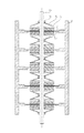
図6に本発明の実施例5に係る動力伝達機構を用いた作動装置の断面図を示す。
FIG. 6 shows a cross-sectional view of an operating device using a power transmission mechanism according to
中央に貫通孔を設けた図1A、図1Bの動力伝達機構を複数用いた構成となっており、中央の貫通孔には軸54が配置されている。圧電素子3を駆動制御回路からの交流電圧を供給するための配線がプリントされた支持板53に固着し、10個の振動子を5個の支持板53を介してハウジング55に固定している。 1A and 1B in which a through-hole is provided in the center, and a plurality of power transmission mechanisms are used, and a shaft 54 is disposed in the central through-hole. The piezoelectric element 3 is fixed to the support plate 53 on which wiring for supplying an AC voltage from the drive control circuit is printed, and ten vibrators are fixed to the housing 55 via the five support plates 53. .
軸54には板バネ51が接着されたナット52が固定され、この板バネ51によって移動体2が振動子1に加圧されて接触している。移動体2、板バネ51、ナット52、および、軸54は一体となって回転するが、移動体2と軸54の間ではスラスト方向の移動が許容されている。振動子1と軸54は接触していないか、あるいは、間に不図示のベアリングを設けることにより、互いに自由に回転することができる。
A nut 52 to which a leaf spring 51 is bonded is fixed to the shaft 54, and the movable body 2 is pressed against and contacts the
振動子1を交互に向きを逆にして対向させることで、支持板53およびナット52の数を減らし、空間を効率良く使用している。
By making the
すべての圧電素子3への交流電圧の供給を行わないときはすべての移動体2が振動子1に圧設され、動力発生源に接続された軸54が回転すると、ナット52、板バネ51、移動体2、振動子1、支持板53を順に介してハウジング55に回転トルクが伝達される。
When the AC voltage is not supplied to all the piezoelectric elements 3, all the moving bodies 2 are pressed against the
すべての圧電素子3へ交流電圧を供給し、すべての移動体2に生じた浮揚力が板バネ52の加圧力よりも大きくなると、すべての移動体2と振動子とが非接触状態となるため軸54による回転トルクはハウジング55に伝達されない。 When AC voltage is supplied to all the piezoelectric elements 3 and the levitation force generated in all the moving bodies 2 becomes larger than the pressure force of the leaf springs 52, all the moving bodies 2 and the vibrators are in a non-contact state. The rotational torque from the shaft 54 is not transmitted to the housing 55.
実施例5では圧電素子3に供給する交流電圧の周波数、電圧を制御するだけでなく、交流電圧を供給する圧電素子3の数を変化させることでも伝達される回転トルクの効率を制御することが可能になる。 In the fifth embodiment, not only is the frequency and voltage of the AC voltage supplied to the piezoelectric element 3 controlled, but also the efficiency of the transmitted rotational torque can be controlled by changing the number of piezoelectric elements 3 that supply the AC voltage. It becomes possible.
なお、上記実施例において例示される構成部品の寸法、形状、それらの相対配置などは、本発明が適用される装置の構成や各種条件により適宜変更されるべきものであり、本発明がそれらの例示に限定されるものではない。 It should be noted that the dimensions, shapes, relative arrangements, and the like of the components exemplified in the above embodiments should be appropriately changed according to the configuration of the apparatus to which the present invention is applied and various conditions. It is not limited to the illustration.
1,11,21,31 振動子
2,12,22,32 移動体
3,13,23,33 電気機械エネルギー変換素子(圧電素子)
4,14,24,34 振動体
5,15,25 振動体に設けられた凸部
6,16,26,36 移動体に設けられた凹部
7,17,27 振動子の移動体との接触面
35 軸部
37 摩擦部材
38 ネオジ磁石
39 ビス
40 出力部材
41 被駆動体
51 板バネ
52 ナット
53 支持板
54 軸
55 ハウジング
1,11,21,31 vibrator 2,12,22,32 moving
4, 14, 24, 34 Vibrating
Claims (6)
前記第一の部材と前記第二の部材とを圧接させるための加圧手段と、
前記第一の部材に設けられた電気機械エネルギー変換素子に交流電圧を供給する制御手段と、を備え、
前記電気機械エネルギー変換素子に交流電圧を供給していないときには前記動力発生源から受けた回転トルクにより前記第1の部材と第2の部材とが一体に回転し、
前記制御手段は、前記交流電圧の電圧値または周波数を制御することで、前記第一の部材に生じる面外振動の振動振幅を制御し、前記加圧手段の加圧力に抗して前記第一の部材と前記第二の部材の間に超音波浮揚現象による浮揚力を発生させるものであって、前記交流電圧の電圧値または周波数を変化させることで、前記第一の部材と前記第二の部材の間で伝達される回転トルクを変化させることを特徴とする動力伝達機構。 A first member, a second member having a said a first member, said a second member, but pressurized contact, of said first member or said second member A power transmission mechanism that transmits rotational torque received by one of the members from a power generation source to the other member,
And pressurizing means for pressing the said second member and said first member,
And control means for supplying an AC voltage to the electro-mechanical energy conversion element provided on said first member,
When the AC voltage is not supplied to the electromechanical energy conversion element, the first member and the second member are integrally rotated by the rotational torque received from the power generation source,
The control means controls a vibration amplitude of out-of-plane vibration generated in the first member by controlling a voltage value or a frequency of the AC voltage, and resists the pressurizing force of the pressurizing means. It is one that generates the levitation force by ultrasonic levitation between the member and the second member, by varying the voltage value or frequency of the AC voltage, wherein the pre-Symbol first member first a power transmission mechanism, characterized in that to change the rotational torque transmitted between the second member.
前記第一の部材と前記第二の部材とを圧接させるための加圧手段と、
前記第一の部材に設けられた電気機械エネルギー変換素子に交流電圧を供給する制御手段と、を備え、
前記制御手段は、前記交流電圧の電圧値または周波数を制御することで、前記第一の部材に生じる面外振動の振動振幅を制御し、前記加圧手段の加圧力に抗して前記第一の部材と前記第二の部材の間に超音波浮揚現象による浮揚力を発生させるものであって、前記交流電圧の電圧値または周波数を変化させることで、前記第一の部材と前記第二の部材の間で伝達される動力を変化させ、
前記第1の部材または前記第2の部材の一方は片面に長手方向に延び、かつ、根元がくびれた凸部を有し、他方の部材は前記凸部と嵌合する凹部を有することを特徴とする動力伝達機構。 A first member and a second member, wherein the first member and the second member are pressed and contacted, and the first member or the second member A power transmission mechanism for transmitting power received from a power generation source to one of the members to the other member,
Pressurizing means for press-contacting the first member and the second member;
Control means for supplying an alternating voltage to the electromechanical energy conversion element provided in the first member,
The control means controls a vibration amplitude of out-of-plane vibration generated in the first member by controlling a voltage value or a frequency of the AC voltage, and resists the pressurizing force of the pressurizing means. Generating a levitation force due to an ultrasonic levitation phenomenon between the first member and the second member, and changing the voltage value or frequency of the AC voltage to change the first member and the second member. Change the power transmitted between the members,
One of the first member or the second member has a convex portion extending in the longitudinal direction on one side and having a constricted root, and the other member has a concave portion that fits the convex portion. Power transmission mechanism.
前記第一の部材と前記第二の部材とを圧接させるための加圧手段と、
前記第一の部材に設けられた電気機械エネルギー変換素子に交流電圧を供給する制御手段と、を備え、
前記第一の部材または前記第二の部材のいずれか一方の部材が支持板を介してハウジングに固定され、
他方の部材が回転軸と一体に回転可能に構成されており、
前記制御手段は、前記交流電圧の電圧値または周波数を制御することで、前記第一の部材に生じる面外振動の振動振幅を制御し、前記加圧手段の加圧力に抗して前記第一の部材と前記第二の部材の間に超音波浮揚現象による浮揚力を発生させるものであって、前記交流電圧の電圧値または周波数を変化させることで、前記第一の部材と前記第二の部材の間で伝達される動力を変化させることを特徴とする動力伝達機構。 A first member and a second member, wherein the first member and the second member are pressed and contacted, and the first member or the second member A power transmission mechanism for transmitting power received from a power generation source to one of the members to the other member,
Pressurizing means for press-contacting the first member and the second member;
Control means for supplying an alternating voltage to the electromechanical energy conversion element provided in the first member,
Either one of the first member and the second member is fixed to the housing via a support plate,
The other member is configured to be rotatable integrally with the rotation shaft,
The control means controls a vibration amplitude of out-of-plane vibration generated in the first member by controlling a voltage value or a frequency of the AC voltage, and resists the pressurizing force of the pressurizing means. Generating a levitation force due to an ultrasonic levitation phenomenon between the first member and the second member, and changing the voltage value or frequency of the AC voltage to change the first member and the second member. A power transmission mechanism characterized by changing power transmitted between members.
Priority Applications (2)
| Application Number | Priority Date | Filing Date | Title |
|---|---|---|---|
| JP2004076393A JP4612798B2 (en) | 2003-04-18 | 2004-03-17 | Power transmission mechanism |
| US10/822,097 US7124870B2 (en) | 2003-04-18 | 2004-04-09 | Power transmitting mechanism and power transmitting method |
Applications Claiming Priority (2)
| Application Number | Priority Date | Filing Date | Title |
|---|---|---|---|
| JP2003114296 | 2003-04-18 | ||
| JP2004076393A JP4612798B2 (en) | 2003-04-18 | 2004-03-17 | Power transmission mechanism |
Publications (3)
| Publication Number | Publication Date |
|---|---|
| JP2004332923A JP2004332923A (en) | 2004-11-25 |
| JP2004332923A5 JP2004332923A5 (en) | 2007-05-10 |
| JP4612798B2 true JP4612798B2 (en) | 2011-01-12 |
Family
ID=33161567
Family Applications (1)
| Application Number | Title | Priority Date | Filing Date |
|---|---|---|---|
| JP2004076393A Expired - Fee Related JP4612798B2 (en) | 2003-04-18 | 2004-03-17 | Power transmission mechanism |
Country Status (2)
| Country | Link |
|---|---|
| US (1) | US7124870B2 (en) |
| JP (1) | JP4612798B2 (en) |
Families Citing this family (7)
| Publication number | Priority date | Publication date | Assignee | Title |
|---|---|---|---|---|
| US7443083B2 (en) | 2005-04-27 | 2008-10-28 | Drexel University | Piezoelectric powered vehicles and motors |
| WO2009084304A1 (en) * | 2007-12-27 | 2009-07-09 | Murata Manufacturing Co., Ltd. | Actuator system and method for controlling the same |
| KR101044216B1 (en) * | 2010-01-04 | 2011-06-29 | 삼성전기주식회사 | Piezoelectric actuator module |
| KR101044130B1 (en) * | 2010-01-04 | 2011-06-24 | 삼성전기주식회사 | Piezoelectric actuator module |
| DE102010024504B4 (en) | 2010-06-21 | 2012-07-26 | Technische Universität Braunschweig | Positioning machine |
| JP5880541B2 (en) * | 2011-03-09 | 2016-03-09 | 株式会社ニコン | Vibration actuator |
| JP6452359B2 (en) * | 2014-09-09 | 2019-01-16 | 国立大学法人信州大学 | Clutch mechanism using gel actuator |
Citations (6)
| Publication number | Priority date | Publication date | Assignee | Title |
|---|---|---|---|---|
| JPH03139180A (en) * | 1989-10-23 | 1991-06-13 | Brother Ind Ltd | Ultrasonic levitating unit |
| JPH05328750A (en) * | 1992-05-25 | 1993-12-10 | Sumitomo Heavy Ind Ltd | Electrostatic actuator |
| JPH06113564A (en) * | 1992-09-29 | 1994-04-22 | Ricoh Co Ltd | Actuator |
| JPH08277033A (en) * | 1995-04-05 | 1996-10-22 | Kaijo Corp | Object conveyance device provided with object floating device |
| JPH10312659A (en) * | 1997-05-14 | 1998-11-24 | Nippon Hoso Kyokai <Nhk> | Magnetic disk driving device |
| JP2000092870A (en) * | 1998-09-16 | 2000-03-31 | Nikon Corp | Vibrating motor |
Family Cites Families (5)
| Publication number | Priority date | Publication date | Assignee | Title |
|---|---|---|---|---|
| DE4443454C2 (en) * | 1994-12-07 | 1997-02-13 | Fichtel & Sachs Ag | Torque transmission device |
| US5942838A (en) * | 1997-08-19 | 1999-08-24 | The Hong Kong University Of Science & Technology | Rotary motor driven by a piezoelectric composite laminate |
| JP4556304B2 (en) | 2000-08-01 | 2010-10-06 | 株式会社デンソー | Electromagnetic clutch |
| JP2002181072A (en) | 2000-12-11 | 2002-06-26 | Akurosu:Kk | Friction single disc clutch |
| US6964327B2 (en) * | 2002-12-11 | 2005-11-15 | Kuo-Tsi Chang | Ultrasonic clutch |
-
2004
- 2004-03-17 JP JP2004076393A patent/JP4612798B2/en not_active Expired - Fee Related
- 2004-04-09 US US10/822,097 patent/US7124870B2/en not_active Expired - Fee Related
Patent Citations (6)
| Publication number | Priority date | Publication date | Assignee | Title |
|---|---|---|---|---|
| JPH03139180A (en) * | 1989-10-23 | 1991-06-13 | Brother Ind Ltd | Ultrasonic levitating unit |
| JPH05328750A (en) * | 1992-05-25 | 1993-12-10 | Sumitomo Heavy Ind Ltd | Electrostatic actuator |
| JPH06113564A (en) * | 1992-09-29 | 1994-04-22 | Ricoh Co Ltd | Actuator |
| JPH08277033A (en) * | 1995-04-05 | 1996-10-22 | Kaijo Corp | Object conveyance device provided with object floating device |
| JPH10312659A (en) * | 1997-05-14 | 1998-11-24 | Nippon Hoso Kyokai <Nhk> | Magnetic disk driving device |
| JP2000092870A (en) * | 1998-09-16 | 2000-03-31 | Nikon Corp | Vibrating motor |
Also Published As
| Publication number | Publication date |
|---|---|
| US7124870B2 (en) | 2006-10-24 |
| JP2004332923A (en) | 2004-11-25 |
| US20040206596A1 (en) | 2004-10-21 |
Similar Documents
| Publication | Publication Date | Title |
|---|---|---|
| EP2242123B1 (en) | Vibration wave driving device | |
| JPH0117353B2 (en) | ||
| JP5641800B2 (en) | Vibration type driving device | |
| US6242850B1 (en) | Piezoelectric motor and a disk drive using same | |
| JPH0241677A (en) | Ultrasonic motor | |
| JP4669222B2 (en) | Piezoelectric drive | |
| JP4612798B2 (en) | Power transmission mechanism | |
| JP3566711B2 (en) | Vibration wave drive | |
| US5440192A (en) | Ultrasonic motor | |
| JPH11346487A (en) | Oscillation wave unit and oscillation wave driver | |
| KR100661311B1 (en) | Piezoelectric ultrasonic motor | |
| JP5349768B2 (en) | Vibration wave drive | |
| JP4979017B2 (en) | Ultrasonic motor and ultrasonic vibrator used therefor | |
| JPH02311184A (en) | Ultrasonic motor | |
| JP2769151B2 (en) | Ultrasonic motor | |
| JPH09327185A (en) | Oscillating actuator | |
| JPH01177878A (en) | Oscillatory wave motor | |
| JP5610707B2 (en) | Vibration wave drive | |
| JPS60162487A (en) | Piezoelectric driving device | |
| JPS62107688A (en) | Small-sized actuator | |
| JPH1094274A (en) | Apparatus with vibration driver | |
| JPH07178370A (en) | Vibrator and vibrating actuator | |
| JP2003209983A (en) | Oscillator and oscillation wave driver | |
| JPS62196080A (en) | Ultrasonic motor | |
| JPH06276767A (en) | Ultrasonic motor |
Legal Events
| Date | Code | Title | Description |
|---|---|---|---|
| A521 | Request for written amendment filed |
Free format text: JAPANESE INTERMEDIATE CODE: A523 Effective date: 20070316 |
|
| A621 | Written request for application examination |
Free format text: JAPANESE INTERMEDIATE CODE: A621 Effective date: 20070316 |
|
| RD04 | Notification of resignation of power of attorney |
Free format text: JAPANESE INTERMEDIATE CODE: A7424 Effective date: 20100201 |
|
| A977 | Report on retrieval |
Free format text: JAPANESE INTERMEDIATE CODE: A971007 Effective date: 20100531 |
|
| A131 | Notification of reasons for refusal |
Free format text: JAPANESE INTERMEDIATE CODE: A131 Effective date: 20100601 |
|
| RD01 | Notification of change of attorney |
Free format text: JAPANESE INTERMEDIATE CODE: A7421 Effective date: 20100630 |
|
| A521 | Request for written amendment filed |
Free format text: JAPANESE INTERMEDIATE CODE: A523 Effective date: 20100730 |
|
| TRDD | Decision of grant or rejection written | ||
| A01 | Written decision to grant a patent or to grant a registration (utility model) |
Free format text: JAPANESE INTERMEDIATE CODE: A01 Effective date: 20101005 |
|
| A01 | Written decision to grant a patent or to grant a registration (utility model) |
Free format text: JAPANESE INTERMEDIATE CODE: A01 |
|
| A61 | First payment of annual fees (during grant procedure) |
Free format text: JAPANESE INTERMEDIATE CODE: A61 Effective date: 20101016 |
|
| FPAY | Renewal fee payment (event date is renewal date of database) |
Free format text: PAYMENT UNTIL: 20131022 Year of fee payment: 3 |
|
| R150 | Certificate of patent or registration of utility model |
Free format text: JAPANESE INTERMEDIATE CODE: R150 |
|
| LAPS | Cancellation because of no payment of annual fees |