JP5347491B2 - Thin film forming equipment - Google Patents
Thin film forming equipment Download PDFInfo
- Publication number
- JP5347491B2 JP5347491B2 JP2008329624A JP2008329624A JP5347491B2 JP 5347491 B2 JP5347491 B2 JP 5347491B2 JP 2008329624 A JP2008329624 A JP 2008329624A JP 2008329624 A JP2008329624 A JP 2008329624A JP 5347491 B2 JP5347491 B2 JP 5347491B2
- Authority
- JP
- Japan
- Prior art keywords
- winding core
- vertical direction
- substrate
- winding
- flexible substrate
- Prior art date
- Legal status (The legal status is an assumption and is not a legal conclusion. Google has not performed a legal analysis and makes no representation as to the accuracy of the status listed.)
- Expired - Fee Related
Links
Images


Classifications
-
- Y—GENERAL TAGGING OF NEW TECHNOLOGICAL DEVELOPMENTS; GENERAL TAGGING OF CROSS-SECTIONAL TECHNOLOGIES SPANNING OVER SEVERAL SECTIONS OF THE IPC; TECHNICAL SUBJECTS COVERED BY FORMER USPC CROSS-REFERENCE ART COLLECTIONS [XRACs] AND DIGESTS
- Y02—TECHNOLOGIES OR APPLICATIONS FOR MITIGATION OR ADAPTATION AGAINST CLIMATE CHANGE
- Y02E—REDUCTION OF GREENHOUSE GAS [GHG] EMISSIONS, RELATED TO ENERGY GENERATION, TRANSMISSION OR DISTRIBUTION
- Y02E10/00—Energy generation through renewable energy sources
- Y02E10/50—Photovoltaic [PV] energy
Abstract
Description
本発明は、可撓性基板を巻き取るための巻取りコアを備える薄膜形成装置に関する。 The present invention relates to a thin film forming apparatus including a winding core for winding a flexible substrate.
薄膜形成装置は、可撓性基板(以下、「基板」という)の表面上に、a−Si系の材料から主に構成される薄膜光電変換素子を含む光電変換層などを成膜するために用いられている。基板を成膜する工程は、薄膜形成装置内に設けられた成膜室内で行なわれる。このような薄膜形成装置の内部で基板を搬送する代表的な方式として、ロールツーロール方式およびステッピングロール方式がある。ロールツーロール方式は、巻出しコアに巻き取られた基板を成膜室に向けて送り出し、成膜室内で基板を移動させながら基板表面上への成膜を行なった後、この基板を巻取りコアによって巻き取る方式である。これに対して、ステッピングロール方式は、成膜室内で基板表面上への成膜を行なう際に、基板の移動を一旦停止する方式となっている。 The thin film forming apparatus forms a photoelectric conversion layer including a thin film photoelectric conversion element mainly composed of an a-Si material on the surface of a flexible substrate (hereinafter referred to as “substrate”). It is used. The step of depositing the substrate is performed in a deposition chamber provided in the thin film forming apparatus. As a typical system for transporting a substrate inside such a thin film forming apparatus, there are a roll-to-roll system and a stepping roll system. In the roll-to-roll method, the substrate wound on the unwinding core is sent out toward the film formation chamber, the film is formed on the substrate surface while moving the substrate in the film formation chamber, and then the substrate is wound up. This is a method of winding with a core. On the other hand, the stepping roll method is a method in which the movement of the substrate is temporarily stopped when the film is formed on the substrate surface in the film forming chamber.
このようなロールツーロール方式およびステッピングロール方式においては、基板の搬送中に発生する基板の位置ズレによって、巻取りコアで基板を巻き取る際に巻きズレが発生することがある。この巻きズレによって基板にはシワが発生し、その結果、基板表面に成膜された薄膜光電変換素子の特性が著しく低下するおそれがある。そこで、このような巻きズレを修正するために、特許文献1の薄膜形成装置は、基板の搬送に用いられるロールを傾けることによって、基板の搬送方向を斜めにしながら基板の位置を修正している。
しかしながら、特許文献1では、基板が、傾けられたロールを通過する際に、ロールの傾斜に対応して急に方向を変えられてロールに向かって斜めに引き込まれることとなる。そのため、基板に強制的な曲げが加えられることとなり、基板には大きな剪断力が発生することとなる。このような剪断力によって基板の搬送方向に対して垂直な方向に延びるシワが発生して、このシワが薄膜光電変換素子の特性を低下させるおそれがある。
However, in
また、特許文献1のように、基板を斜めに傾けて基板の位置を少しずつ修正するという構成では、基板の巻きズレを迅速に修正するという点と、巻きズレを高い精度で修正するという点とで、依然として問題がある。このような問題によって、巻きズレによるシワが発生し、薄膜光電変換素子の特性が低下するおそれがある。
In addition, as in
本発明は、このような実情に鑑みてなされたものであって、その目的は、基板の巻きズレを確実に修正することによって基板のシワの発生を防止可能な薄膜形成装置を提供することである。 The present invention has been made in view of such circumstances, and an object of the present invention is to provide a thin film forming apparatus capable of preventing the generation of wrinkles on a substrate by reliably correcting the winding deviation of the substrate. is there.
課題を解決するために本発明の薄膜形成装置は、フィルム形状の表面を垂直方向に沿わせた状態で搬送される可撓性基板を成膜するための薄膜形成装置であって、垂直方向に沿った回転軸を中心に回転することによって前記可撓性基板を巻取り可能に構成される巻取りコアと、垂直方向に沿った回転軸を中心に回転可能に構成され、かつ前記可撓性基板を前記巻取りコアに向けてガイドするように前記巻取りコアより前記可撓性基板の搬送方向上流側に配置されるガイドロールと、前記可撓性基板の縁部分を検出するように構成され、かつ前記ガイドロールより前記可撓性基板の搬送方向上流側に配置されるセンサとを備え、前記センサが、前記可撓性基板の搬送時に発生する位置変化を検出し、前記巻取りコア、前記ガイドロールおよび前記センサが、共に、前記センサにより検出された前記可撓性基板の縁部分の位置変化に対応して前記可撓性基板に相対して垂直方向に移動可能に構成されている。 In order to solve the problems, a thin film forming apparatus of the present invention is a thin film forming apparatus for forming a flexible substrate that is transported in a state in which a film-shaped surface is aligned in a vertical direction. A winding core configured to be capable of winding the flexible substrate by rotating about a rotating axis along the axis, and configured to be rotatable about a rotating axis along a vertical direction, and the flexible A guide roll disposed upstream of the winding core in the transport direction of the flexible substrate so as to guide the substrate toward the winding core, and an edge portion of the flexible substrate are detected. And a sensor arranged upstream of the guide roll in the conveyance direction of the flexible substrate, and the sensor detects a positional change that occurs during conveyance of the flexible substrate, and the winding core The guide roll and the front Sensors, both are configured to be movable in the vertical direction relative to the flexible substrate corresponding to the position change of the detected edge portion of the flexible substrate by the sensor.
また、本発明において薄膜形成装置は、次のように構成することが好ましい。
前記巻取りコアの垂直方向の下端部から前記巻取りコアの回転軸に沿って延設される下側シャフトが、前記巻取りコアの回転軸に沿って回転するように駆動し、かつ垂直方向に移動可能に構成されており、前記巻取りコアが、前記可撓性基板を巻き取るように前記下側シャフトとともに回転するように構成され、前記巻取りコア、前記ガイドロール、前記センサおよび前記下側シャフトが共に垂直方向に移動可能に構成されている。
この場合、前記巻取りコアの垂直方向の上端部から前記巻取りコアの回転軸に沿って延設される上側シャフトが、前記下側シャフトとは別体に構成されており、前記下側シャフトと協働して前記巻取りコアに圧力を加えながら前記巻取りコアを挟持し、かつ前記下側シャフトおよび前記巻取りコアとともに回転するように構成されており、前記巻取りコア、前記ガイドロール、前記センサ、前記下側シャフトおよび前記上側シャフトが共に垂直方向に移動可能に構成されることが好ましい。
In the present invention, the thin film forming apparatus is preferably configured as follows.
A lower shaft extending from the lower end portion of the winding core in the vertical direction along the rotation axis of the winding core is driven to rotate along the rotation axis of the winding core, and the vertical direction The winding core is configured to rotate with the lower shaft so as to wind up the flexible substrate, and the winding core, the guide roll , the sensor, and the Both lower shafts are configured to be movable in the vertical direction.
In this case, the upper shaft extending along the rotation axis of the winding core from the upper end in the vertical direction of the winding core is configured separately from the lower shaft, and the lower shaft and cooperatively sandwiching the winding core while applying a pressure to the winding core, and is configured to rotate together with said lower shaft and the winding core, the winding core, the guide roll Preferably, the sensor, the lower shaft, and the upper shaft are all configured to be movable in the vertical direction.
さらに、本発明において薄膜形成装置は、次のように構成することが好ましい。
前記巻取りコアの垂直方向の下端部から前記巻取りコアの回転軸に沿って延設される下側シャフトが、前記巻取りコアの回転軸に沿って回転するように駆動し、かつ垂直方向に移動可能に構成されており、前記巻取りコアの垂直方向の上端部から前記巻取りコアの回転軸に沿って延設される上側シャフトが、前記下側シャフトと一体に形成されており、前記巻取りコアが、前記下側シャフトおよび前記上側シャフトによって圧力を加えながら挟持されて前記下側シャフトおよび前記上側シャフトとともに回転するように構成され、前記巻取りコア、前記ガイドロール、前記センサ、前記下側シャフトおよび前記上側シャフトが共に垂直方向に移動可能に構成されている。
Furthermore, in the present invention, the thin film forming apparatus is preferably configured as follows.
A lower shaft extending from the lower end portion of the winding core in the vertical direction along the rotation axis of the winding core is driven to rotate along the rotation axis of the winding core, and the vertical direction The upper shaft extending along the rotation axis of the winding core from the upper end in the vertical direction of the winding core is formed integrally with the lower shaft, The winding core is configured to be sandwiched while applying pressure by the lower shaft and the upper shaft and rotate together with the lower shaft and the upper shaft, and the winding core, the guide roll, the sensor, Both the lower shaft and the upper shaft are configured to be movable in the vertical direction.
本発明の薄膜形成装置によれば、以下の効果を得ることができる。本発明の薄膜形成装置は、フィルム形状の表面を垂直方向に沿わせた状態で搬送される可撓性基板を成膜するための薄膜形成装置であって、垂直方向に沿った回転軸を中心に回転することによって前記可撓性基板を巻取り可能に構成される巻取りコアと、垂直方向に沿った回転軸を中心に回転可能に構成され、かつ前記可撓性基板を前記巻取りコアに向けてガイドするように前記巻取りコアより前記可撓性基板の搬送方向上流側に配置されるガイドロールと、前記可撓性基板の縁部分を検出するように構成され、かつ前記ガイドロールより前記可撓性基板の搬送方向上流側に配置されるセンサとを備え、前記センサが、前記可撓性基板の搬送時に発生する位置変化を検出し、前記巻取りコア、前記ガイドロールおよび前記センサが、共に、前記センサにより検出された前記可撓性基板の縁部分の位置変化に対応して前記可撓性基板に相対して垂直方向に移動可能に構成されている。そのため、前記巻取りコアおよび前記ガイドロールが、前記可撓性基板の位置変化に迅速に対応して、前記可撓性基板に相対して垂直方向にスライドし、前記可撓性基板の巻きズレを迅速かつ正確に修正できる。特に前記ガイドロールのスライド移動による修正においては、前記ガイドロールの引き込みによって発生する大きな曲げが前記可撓性基板に加えられないため、前記可撓性基板に剪断力が発生し難くなっている。よって、この剪断力によるシワの発生を確実に防止しながら、前記可撓性基板の巻きズレを正確に修正できる。 According to the thin film forming apparatus of the present invention, the following effects can be obtained. The thin film forming apparatus of the present invention is a thin film forming apparatus for forming a flexible substrate that is transported in a state in which the surface of the film shape is aligned along the vertical direction, and the rotation axis along the vertical direction is the center. A take-up core configured to be able to take up the flexible substrate by rotating in the direction of rotation, and to be configured to be rotatable about a rotation axis along a vertical direction. A guide roll disposed upstream of the winding core in the transport direction of the flexible substrate so as to be guided toward the winding core, and an edge portion of the flexible substrate, and the guide roll A sensor disposed on the upstream side in the transport direction of the flexible substrate, the sensor detects a change in position that occurs during transport of the flexible substrate, and the winding core, the guide roll, and the Both sensors are in front And it is movable in the vertical direction relative to the flexible substrate corresponding to the position change of the detected edge portion of the flexible substrate by a sensor. Therefore, the winding core and the guide roll slide in a vertical direction relative to the flexible substrate in response to a change in the position of the flexible substrate, so that the winding displacement of the flexible substrate is reduced. Can be corrected quickly and accurately. In particular, in the correction by sliding movement of the guide roll, since a large bending generated by the pulling of the guide roll is not applied to the flexible substrate, a shearing force is hardly generated on the flexible substrate. Therefore, the winding deviation of the flexible substrate can be accurately corrected while reliably preventing the generation of wrinkles due to the shearing force.
また、本発明において、前記巻取りコアの垂直方向の下端部から前記巻取りコアの回転軸に沿って延設される下側シャフトが、前記巻取りコアの回転軸に沿って回転するように駆動し、かつ垂直方向に移動可能に構成されており、前記巻取りコアが、前記可撓性基板を巻き取るように前記下側シャフトとともに回転するように構成され、前記巻取りコア、前記ガイドロール、前記センサおよび前記下側シャフトが共に垂直方向に移動可能に構成されており、前記巻取りコアを回転させながら垂直方向に移動させる機能が、前記下側シャフトのようなシンプルな構成によって取扱い易くなっている。このような取扱い易い構成によって、正確な前記可撓性基板の巻きズレの修正がより容易に実現できる。 Further, in the present invention, a lower shaft extending along a rotation axis of the winding core from a lower end portion in a vertical direction of the winding core is rotated along the rotation axis of the winding core. The winding core is configured to be driven and movable in the vertical direction, and the winding core is configured to rotate with the lower shaft so as to wind up the flexible substrate, and the winding core, the guide The roll , the sensor, and the lower shaft are all configured to be movable in the vertical direction, and the function of moving the winding core in the vertical direction while rotating is handled by a simple configuration like the lower shaft. It is easy. With such an easy-to-handle configuration, accurate correction of the winding deviation of the flexible substrate can be realized more easily.
さらに、前記巻取りコアの垂直方向の上端部から前記巻取りコアの回転軸に沿って延設される上側シャフトが、前記下側シャフトとは別体に構成されており、前記下側シャフトと協働して前記巻取りコアに圧力を加えながら前記巻取りコアを挟持し、かつ前記下側シャフトおよび前記巻取りコアとともに、回転するように構成されており、前記巻取りコア、前記ガイドロール、前記センサ、前記下側シャフトおよび前記上側シャフトが共に垂直方向に移動可能に構成されており、前記巻取りコアに加えられる前記上側シャフトの圧力によって、前記上側シャフトおよび前記下側シャフトが前記巻取りコアを確実に挟持することができる。そのため、前記巻取りコアを回転させながら、垂直方向に移動させる機能が、前記下側シャフト、および前記下側シャフトとは別体の前記上側シャフトのようなシンプルな構成によって、取扱い易くなっている。このような取扱い易い構成によって、正確な前記可撓性基板の巻きズレの修正がより容易に実現できる。 Furthermore, the upper shaft extending along the rotation axis of the winding core from the vertical upper end of the winding core is configured separately from the lower shaft, and the lower shaft The winding core is configured to sandwich the winding core while applying pressure to the winding core and rotate together with the lower shaft and the winding core, and the winding core and the guide roll. The sensor, the lower shaft, and the upper shaft are all configured to be movable in the vertical direction, and the upper shaft and the lower shaft are wound by the pressure of the upper shaft applied to the winding core. The take-up core can be securely held. Therefore, the function of moving the winding core in the vertical direction while rotating the winding core is easy to handle by a simple configuration such as the lower shaft and the upper shaft that is separate from the lower shaft. . With such an easy-to-handle configuration, accurate correction of the winding deviation of the flexible substrate can be realized more easily.
また、本発明において、前記巻取りコアの垂直方向の下端部から前記巻取りコアの回転軸に沿って延設される下側シャフトが、前記巻取りコアの回転軸に沿って回転するように駆動し、かつ垂直方向に移動可能に構成されており、前記巻取りコアの垂直方向の上端部から前記巻取りコアの回転軸に沿って延設される上側シャフトが、前記下側シャフトと一体に形成されており、前記巻取りコアが、前記下側シャフトおよび前記上側シャフトによって圧力を加えながら挟持されて前記下側シャフトおよび前記上側シャフトとともに回転するように構成され、前記巻取りコア、前記ガイドロール、前記センサ、前記下側シャフトおよび前記上側シャフトが共に垂直方向に移動可能に構成されており、一体に構成された前記下側シャフトおよび前記上側シャフトが、前記巻取りコアを垂直方向上下から確実に挟持されることとなる。そのため、前記下側シャフトおよび前記上側シャフトを一体にしたシンプルな構成によって、前記巻取りコアを回転させながら垂直方向に移動させる機能が、取扱い易くなっている。このような取扱い易い構成によって、正確な前記可撓性基板の巻きズレの修正がより容易に実現できる。 Further, in the present invention, a lower shaft extending along a rotation axis of the winding core from a lower end portion in a vertical direction of the winding core is rotated along the rotation axis of the winding core. An upper shaft that is driven and movable in the vertical direction and that extends from the vertical upper end of the winding core along the rotation axis of the winding core is integrated with the lower shaft. The winding core is sandwiched while applying pressure by the lower shaft and the upper shaft and rotates together with the lower shaft and the upper shaft, and the winding core, The guide roll, the sensor, the lower shaft, and the upper shaft are both configured to be movable in the vertical direction, and the lower shaft and the integrally configured Side shaft, and is surely held between the winding core from the vertical direction above and below. Therefore, the function of moving the winding core in the vertical direction while rotating the winding core is easy to handle with a simple configuration in which the lower shaft and the upper shaft are integrated. With such an easy-to-handle configuration, accurate correction of the winding deviation of the flexible substrate can be realized more easily.
[第1実施形態]
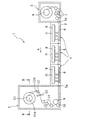
本発明の第1実施形態における薄膜形成装置(以下、「装置」という)について以下に説明する。図1は、本発明の実施形態における装置1の内部構造を概略的に表す平面図である。装置1は、フィルム形状に形成される可撓性基板(以下、「基板」という)2の表面を成膜する構成となっている。装置1には、巻出室3と、成膜室4と、巻取室5とが設けられており、基板2を、巻出室3、成膜室4、巻取室5の順に、矢印Aで示す搬送方向に沿って搬送する構成となっている。また、巻出室3、成膜室4および巻取室5の内部は、成膜時に真空状態とすることが可能なように構成されている。
[First Embodiment]
A thin film forming apparatus (hereinafter referred to as “apparatus”) in the first embodiment of the present invention will be described below. FIG. 1 is a plan view schematically showing the internal structure of a
巻出室3の内部には、基板2を巻いた状態の巻出しコア6が、垂直方向に沿った回転軸を中心に回転可能に設けられており、さらに、基板2を巻出しコア6から巻出室3の搬出口3aまで搬送するための搬送ロール7が設けられている。
Inside the
成膜室4には、巻出室3から送り出された基板2が通過するように構成されている。成膜室4の内部には、基板2を成膜するために用いられる一対の電極8が設けられている。基板2は、一対の電極8間を通過するとともに、この一対の電極8間に電極を印加することによって成膜されることとなる。
The film forming chamber 4 is configured such that the
巻取室5には、成膜された後の基板2を搬入するための搬入口5aが設けられている。巻取室5の内部には、基板2を搬送するために駆動可能なドライブロール9と、このドライブロール9と協働して基板2を挟むためのプレスロール10とが設けられている。さらに、巻取室5の内部には、基板2を巻き取るための巻取りコア11が設けられ、巻取りコア11の搬送方向上流側の近傍にガイドロール12が設けられている。これらの巻取りコア11およびガイドロール12は、垂直方向に沿ったそれぞれの回転軸11a,12aを中心に回転可能に構成されている。
The take-
さらに、ガイドロール12の搬送方向上流の近傍には、センサ13が設けられている。このセンサ13は、垂直方向における基板2の縁部分の位置を検出可能に構成されている。センサ13は、特に非接触式センサであると好ましく、このような非接触式センサの一例として、透過型のレーザーセンサ、および反射型のフォトセンサなどが挙げられる。このセンサ13とドライブロール9およびプレスロール10との間の搬送区間には、テンションロール14が設けられている。
Further, a
図2は、第1実施形態の場合における図1のB−B断面図である。巻取りコア11の下端部には、下側シャフト15が配置されている。下側シャフト15の上端部には、下側テーパコーン部15aが設けられており、下側テーパコーン部15aは、上方から下方に向かって広がる略円錐形状に形成されている。また、巻取りコア11の回転軸11aに沿って、テーパコーン部15aの下部から下方に向かって延びる下側シャフト部15bが設けられている。
2 is a cross-sectional view taken along the line BB of FIG. 1 in the case of the first embodiment. A
一方で、巻取りコア11の上端部には、下側シャフト15とは別体で構成される上側シャフト16が配置されている。上側シャフト16の下端部には、上側テーパコーン部16aが設けられており、上側テーパコーン部16aは、下方から上方に向かって広がる略円錐形状に形成されている。また、巻取りコア11の回転軸11aに沿って、上側テーパコーン部16aの上部から上方に向かって延びる上側シャフト部16bが設けられている。上側テーパコーン部16aは、上側シャフト部16bに対して、巻取りコア11の回転軸11aを中心に回転可能に取り付けられている。
On the other hand, an
巻取りコア11は、垂直方向に沿って延びる円筒形状に形成されており、このような巻取りコア11の下端部で下側テーパコーン15aが嵌合し、巻取りコア11の上端部で上側テーパコーン16aが嵌合している。このような構成により、巻取りコア11と、下側シャフト15と、上側シャフト16とは、同一の回転軸11aを中心に回転することとなる。
The winding
下側シャフト部15bは、巻取室5の下部から巻取室5の外部に向かって延びており、下側シャフト部15bの外周には軸受17が、下側シャフト15を回転可能とするように取付けられている。さらに、軸受17と巻取室5との間には、軸受17を垂直方向にスライド可能に支持するための下側直線ガイド18が設けられている。軸受17と下側直線ガイド18とは、巻取室5を真空に保つための真空シール構造を備えている。
The
また、軸受17の下部は、巻取室5の外部で下側可動部材19に取付けられている。この下側可動部材19は、下側直線ガイド18と垂直方向に間隔を空けて配置されており、この下側可動部材19と下側直線ガイド18との間には、垂直方向に伸縮可能な弾性部材の一例として、ベローズ20が挟まれて配置されている。さらに、ベローズ20は、軸受17の外周表面を囲むように配置されている。下側シャフト部15bの下端部には、モータ21が取付けられている。このモータ21の回転駆動によって、下側シャフト15aが回転し、この回転に伴って巻取りコア11および上側テーパコーン部16aが回転することとなる。
The lower part of the
また、下側可動部材19は、巻取室5の下部に設けられた外部直線ガイド22に対して垂直方向にスライド可能に取付けられるスライド部19aを備えている。また、下側可動部材19には、垂直方向に上下動可能とするためにアクチュエータ23の可動部分23aが取付けられている。このアクチュエータ23の固定部分23bは巻取室5の外部、例えば製造ラインの床面に設置されている。
Further, the lower
さらに、アクチュエータ23が作動しない状態でも、下側可動部材19が、上下方向の可動範囲の中間に位置するように、下側可動部材19を上方に持ち上げるための重り24が取付けられている。その結果、巻取りロール11およびガイドロール12もまた、アクチュエータ23が作動しない状態で、上下方向の可動範囲の中間に位置することができる。
Further, a
一方で、上側シャフト部16bは、巻取室5の上部から外部に向かって延びており、上側シャフト部16bと巻取室5との間には、上側シャフト部16bを垂直方向にスライド可能とするための第1上側直線ガイド25が設けられている。この第1上側直線ガイド25は、巻取室5の内部を真空に保つための真空シール構造を有している。また、上側シャフト部16bの上端部には、ピストン部16cが設けられている。このピストン部16cは、下方に向かって開口するシリンダ26内に収納されている。そのため、ピストン部16cの上側部分とシリンダ26とに囲まれた空間27が形成されることとなる。
On the other hand, the
シリンダ26には、空間27内を加圧または減圧するために流体を供給または排出可能に構成される圧力管28が接続され、圧力管28には空間27内の圧力を制御するための圧力レギュレータ29が設けられている。この空間27内の圧力が上げられた場合、ピストン部16cが押下げられて、上側シャフト16の上側テーパコーン部16aが、巻取りコア11の上端部に押付けられることとなる。このような状態で、巻取りコア11は、下側テーパコーン部15aと上側テーパコーン部16aとによって、圧力を加えられながら挟持されることとなる。一方で、この空間27内の圧力が下げられた場合、ピストン部16cが上方に向かって移動可能となり、上側シャフト16が上方に向かって移動可能となる。
The
軸受17にはガイドロール12に向かって延びる支持部材30が取り付けられており、この支持部材30には、ガイドロール12の下端部が回転軸12aを中心に回転可能に取付けられている。一方で、ガイドロール12の上端部は、巻取室5の上部に設けられた第2上側直線ガイド31に、回転軸12aを中心に回転可能に、かつ垂直方向にスライド可能に取付けられている。
A
さらに、図2では図示しないが、センサ13が、巻取りコア11、ガイドロール12、下側シャフト15および上側シャフト16と共に、垂直方向に移動可能に取付けられている。
Further, although not shown in FIG. 2, the
ここで基板2の搬送動作について説明する。
巻出室3内で巻出しコア6に巻き取られた状態にある基板2は、巻出しコア6から送り出されて、搬送ロール7により巻出室3の搬出口3aまで案内されて、搬出口3aから搬出される。その後、基板2は成膜室4を通過し、この通過中に一対の電極8間で電圧を印加することによって基板2が成膜されることとなる。この成膜時に、基板2は、ロールツーロール方式で移動しながら成膜されてもよく、ステッピングロール方式で一旦停止した状態で成膜されてもよい。成膜された後の基板2は、巻取室5の搬入口5aから巻取室5の内部に入り、ドライブロール9とプレスロール10との間に挟まれて通過した後、テンションロール14によって張力を加えられながら、ガイドロール12に向かって案内される。ここで、テンションロール14とガイドロール12との間の搬送区間では、センサ13によって基板2の縁部分の位置が検出される。さらに、ガイドロール12を通過した基板2は、巻取りコア11によって巻き取られる。
Here, the conveyance operation of the
The
さらに、基板2の巻取り動作について説明する。
基板2は、ガイドロール12の位置まで搬送された後に、ガイドロール12に巻きつき、巻取りコア11に向かって搬送されるようにガイドされて、巻取りコア11によって巻き取られる。このとき、基板2は、巻取りコア11をモータ21の駆動により回転させることによって、巻取りコア11に巻き取られながら搬送されている。
Further, the winding operation of the
After the
このような基板2の巻き取り過程において、基板2がガイドロール12を通過する前に、基板2の垂直方向の位置ズレが発生した場合、この位置ズレをガイドロール12の搬送方向上流に配置したセンサ13により検出する。このように検出された位置ズレに合わせて、アクチュエータ23を垂直方向に移動させるように制御する。このアクチュエータ23の作動によって、下側シャフト15が上下動するとともに、巻取りコア11、ガイドロール12およびセンサ13が、基板2に相対して上下動し、基板2の巻き取り位置が修正されることとなる。このとき、巻取りコア11の上下動に追従して上側シャフト16が移動することとなる。この上側シャフト16の移動に際して、圧力レギュレータ29は、空間27の圧力を制御することによって、上側シャフト16を巻取りコア11の上端部に押付ける力を制御する。そのため、下側シャフト15と上側シャフト16とによって巻取りコア11を挟持する圧力は、下側シャフト15の回転を巻取りコア11に伝え、かつ下側テーパコーン15aと上側テーパコーン16aとによって巻取りコア11を確実に挟持可能な大きさに維持されることとなる。
In such a winding process of the
以上のように本発明の第1実施形態によれば、巻取りコア11およびガイドロール12が、基板2の位置変化に迅速に対応して、基板2に相対して垂直方向にスライドし、基板2の巻きズレを迅速かつ正確に修正できる。特にガイドロール12のスライド移動による修正においては、ガイドロール12の引き込みによって発生する大きな曲げが基板2に加えられないため、基板2に剪断力が発生し難くなっている。よって、この剪断力によるシワの発生が確実に防止しながら、基板2の巻きズレを正確に修正できる。
As described above, according to the first embodiment of the present invention, the winding
さらに、巻取りコア11を回転させながら垂直方向に移動させる機能が、下側シャフト15のようなシンプルな構成によって、取扱い易くなっている。このような取扱い易い構成によって、正確な基板2の巻きズレの修正がより容易に実現できる。
Furthermore, the function of moving the winding
加えて、巻取りコア11に加えられる上側シャフト16の圧力によって、下側シャフト15および上側シャフト16が巻取りコア11を確実に挟持することができる。そのため、巻取りコア11を回転させながら、垂直方向に移動させる機能が、下側シャフト15、および下側シャフト15とは別体の上側シャフト16のようなシンプルな構成によって、取扱い易くなっている。このような取扱い易い構成によって、正確な基板2の巻きズレの修正がより容易に実現できる。
In addition, the
[第2実施形態]
本発明の第2実施形態における装置41について説明する。第2実施形態の装置41は、基本的な構成を第1実施形態の装置1と同様とする。第1実施形態と同様な要素は、第1実施形態と同様の符号および名称を用いて説明する。ここでは、第1実施形態と異なる構成について説明する。
[Second Embodiment]
An
図3は、第2実施形態の場合における図1のB−B断面図である。巻取室42の外部で把持機構43によって把持されている。この把持機構43は、上側可動部材44に取付けられている。この上側可動部材44は、第1上側直線ガイド25と垂直方向に間隔を空けて配置されており、この第1上側直線ガイド25と上側可動部材44との間に垂直方向に伸縮可能な弾性部材の一例として、ベローズ45が挟まれて配置されている。さらに、ベローズ45は、上側シャフト部16bの外周表面を囲むように形成されている。上側可動部材44は、巻取室42の上部に設けられた外部直線ガイド46に対して垂直方向にスライド可能に取付けられるスライド部44aを備えている。
FIG. 3 is a cross-sectional view taken along the line BB in FIG. 1 in the case of the second embodiment. It is gripped by the gripping
さらに、下側可動部材19と上側可動部材44とは、上下方向に延びる連結部材47によって連結されている。このとき、巻取りコア11は、下側テーパコーン15aと上側テーパコーン16aとによって、下側シャフト15の回転を巻取りコア11に伝えるために十分な圧力を加えられた状態で挟持されている。このように一体に形成された下側可動部材19と、上側可動部材44と、連結部材47とは、アクチュエータ48によって垂直方向に上下動させられるように構成されている。このアクチュエータ48の可動部分48aは、連結部材47に取付けられており、アクチュエータ48の固定部分48bは、巻取室42の外側の側部に取付けられている。
Further, the lower
さらに、アクチュエータ48が作動しない状態でも、一体に構成された下側可動部材19、上側可動部材44および連結部材47が、上下方向の可動範囲の中間に位置するように、一体に構成された下側可動部材19、上側可動部材44および連結部材47を上方に持ち上げるための重り49が取付けられている。その結果、巻取りロール11およびガイドロール12もまた、アクチュエータ48が作動しない状態で、上下方向の可動範囲の中間に位置することができる。なお、図3では図示しないが、センサ13が、巻取りコア11、ガイドロール12、下側シャフト15および上側シャフト16と共に、垂直方向に移動可能に取付けられている。
Further, even when the actuator 48 is not operated, the lower
基板2の搬送動作については、第1実施形態と同様となっているが、基板2の巻取り動作については、巻取りコア11およびガイドロール12の上下動が第1実施形態と異なっている。基板2の巻き取り動作に際して、基板2がガイドロール12を通過する前に、基板2の垂直方向の位置ズレが発生した場合、この位置ズレをガイドロール12の搬送方向上流に配置したセンサ13により検出する。このように検出された位置ズレに合わせて、アクチュエータ48を垂直方向に移動させるように制御する。このアクチュエータ48の作動によって、下側シャフト15および上側シャフト16が共に上下動するとともに、巻取りコア11、ガイドロール12およびセンサ13が、基板2に相対して上下動して、基板2の巻き取り位置が修正されることとなる。このとき、下側シャフト15と上側シャフト16とによって巻取りコア11を挟持する圧力は、下側シャフト15の回転を巻取りコア11に伝え、かつ下側テーパコーン15aと上側テーパコーン16aとによって巻取りコア11を確実に挟持可能な大きさに維持されている。
The transporting operation of the
以上のように本発明の第2実施形態によれば、第1実施形態と同様の構成によって、基板2におけるシワの発生を確実に防止しながら、基板2の巻きズレを正確に修正できる。
As described above, according to the second embodiment of the present invention, the winding deviation of the
また、一体に構成された下側シャフト15および上側シャフト16が、巻取りコア11を垂直方向上下から確実に挟持されることとなる。そのため、下側シャフト15および上側シャフト16のようなシンプルな構成によって、巻取りコア11を回転させながら垂直方向に移動させる機能が、取扱い易くなっている。このような取扱い易い構成によって、正確な基板2の巻きズレの修正がより容易に実現できる。
In addition, the
ここまで本発明の実施形態について述べたが、本発明は既述の実施形態に限定されるものではなく、本発明の技術的思想に基づいて各種の変形および変更が可能である。 Although the embodiments of the present invention have been described so far, the present invention is not limited to the above-described embodiments, and various modifications and changes can be made based on the technical idea of the present invention.
1,41 薄膜形成装置(装置)
2 可撓性基板(基板)
3 巻出室
4 成膜室
5,42 巻取室
6 巻出しコア
7 搬送ロール
8 電極
9 ドライブロール
10 プレスロール
11 巻取りコア
11a,12a 回転軸
12 ガイドロール
13 センサ
14 テンションロール
15 下側シャフト
15a 下側テーパコーン部
15b 下側シャフト部
16 上側シャフト
16a 上側テーパコーン部
16b 上側シャフト部
16c ピストン部
17 軸受
18 下側直線ガイド
19 下側可動部材
19a スライド部
20,45 ベローズ
21 モータ
22,46 外部直線ガイド
23,48 アクチュエータ
23a,48a 可動部分
23b,48b 固定部分
24,49 重り
25 第1上側直線ガイド
26 シリンダ
27 空間
28 圧力管
29 圧力レギュレータ
30 支持部材
31 第2上側直線ガイド
43 把持機構
44 上側可動部材
44a スライド部
47 連結部材
A 矢印
1,41 Thin film forming equipment
2 Flexible substrate (substrate)
3 Unwinding chamber 4
Claims (4)
垂直方向に沿った回転軸を中心に回転することによって前記可撓性基板を巻取り可能に構成される巻取りコアと、
垂直方向に沿った回転軸を中心に回転可能に構成され、かつ前記可撓性基板を前記巻取りコアに向けてガイドするように前記巻取りコアより前記可撓性基板の搬送方向上流側に配置されるガイドロールと、
前記可撓性基板の縁部分を検出するように構成され、かつ前記ガイドロールより前記可撓性基板の搬送方向上流側に配置されるセンサと
を備え、
前記センサが、前記可撓性基板の搬送時に発生する位置変化を検出し、
前記巻取りコア、前記ガイドロールおよび前記センサが、共に、前記センサにより検出された前記可撓性基板の縁部分の位置変化に対応して前記可撓性基板に相対して垂直方向に移動可能に構成されている、薄膜形成装置。 A thin film forming apparatus for forming a flexible substrate that is transported in a state in which a film-shaped surface is aligned in a vertical direction,
A winding core configured to be capable of winding the flexible substrate by rotating around a rotation axis along a vertical direction;
It is configured to be rotatable about a rotation axis along the vertical direction, and is upstream of the winding core in the conveyance direction of the flexible substrate so as to guide the flexible substrate toward the winding core. A guide roll to be arranged;
A sensor configured to detect an edge portion of the flexible substrate and disposed upstream of the guide roll in the transport direction of the flexible substrate, and
The sensor detects a change in position that occurs during conveyance of the flexible substrate,
The winding core, the guide roll, and the sensor can all move in the vertical direction relative to the flexible substrate in response to a change in the position of the edge of the flexible substrate detected by the sensor. A thin film forming apparatus configured as described above.
Priority Applications (1)
| Application Number | Priority Date | Filing Date | Title |
|---|---|---|---|
| JP2008329624A JP5347491B2 (en) | 2008-12-25 | 2008-12-25 | Thin film forming equipment |
Applications Claiming Priority (1)
| Application Number | Priority Date | Filing Date | Title |
|---|---|---|---|
| JP2008329624A JP5347491B2 (en) | 2008-12-25 | 2008-12-25 | Thin film forming equipment |
Publications (2)
| Publication Number | Publication Date |
|---|---|
| JP2010150599A JP2010150599A (en) | 2010-07-08 |
| JP5347491B2 true JP5347491B2 (en) | 2013-11-20 |
Family
ID=42569993
Family Applications (1)
| Application Number | Title | Priority Date | Filing Date |
|---|---|---|---|
| JP2008329624A Expired - Fee Related JP5347491B2 (en) | 2008-12-25 | 2008-12-25 | Thin film forming equipment |
Country Status (1)
| Country | Link |
|---|---|
| JP (1) | JP5347491B2 (en) |
Families Citing this family (2)
| Publication number | Priority date | Publication date | Assignee | Title |
|---|---|---|---|---|
| JP6472592B2 (en) | 2012-04-18 | 2019-02-20 | キヤノンメディカルシステムズ株式会社 | Magnetic resonance imaging apparatus and magnetic resonance imaging method |
| CN115466923A (en) * | 2022-09-21 | 2022-12-13 | 深圳市和胜金属技术有限公司 | PVD (physical vapor deposition) film coating method |
Family Cites Families (4)
| Publication number | Priority date | Publication date | Assignee | Title |
|---|---|---|---|---|
| JP2902944B2 (en) * | 1994-06-02 | 1999-06-07 | 株式会社富士電機総合研究所 | Manufacturing equipment for thin-film photoelectric conversion elements |
| JP3208639B2 (en) * | 1995-03-10 | 2001-09-17 | ヒラノ光音株式会社 | Surface treatment method and surface treatment apparatus for continuous sheet material |
| JP2001303249A (en) * | 2000-04-19 | 2001-10-31 | Hirano Koon Kk | Surface treatment apparatus for strip-like sheet |
| JP5109301B2 (en) * | 2006-07-27 | 2012-12-26 | 富士電機株式会社 | Film forming apparatus and film forming method |
-
2008
- 2008-12-25 JP JP2008329624A patent/JP5347491B2/en not_active Expired - Fee Related
Also Published As
| Publication number | Publication date |
|---|---|
| JP2010150599A (en) | 2010-07-08 |
Similar Documents
| Publication | Publication Date | Title |
|---|---|---|
| US8870480B2 (en) | Roll-to-roll printing system | |
| KR102192738B1 (en) | Apparatus for Stacking Machine for Secondary Battery Electrode Having Improved Edge Position Control Function for Seperator | |
| CN205662113U (en) | Permanent tension intelligence is rectified and is receive and release a roll system | |
| JPWO2010087218A1 (en) | Position control device for flexible substrate | |
| US8528725B2 (en) | Flexible substrate conveying device | |
| EP2514852A1 (en) | Conveyance device for film substrate | |
| TW200948699A (en) | Roller alignment | |
| JP2019218203A (en) | Glass roll manufacturing method | |
| JP2008031505A (en) | Film deposition apparatus and film deposition method | |
| JP5347491B2 (en) | Thin film forming equipment | |
| JP2012166896A (en) | Web winder | |
| JP2012236676A (en) | Device of correcting winding deviation of film and method of correcting winding deviation | |
| US20160272453A1 (en) | Tension control device and continuous web processing method using same | |
| JP2012236675A (en) | Device of correcting winding deviation of glass film and method of correcting winding deviation | |
| WO2011016471A1 (en) | Apparatus for producing a thin-film lamination | |
| JP2009038277A (en) | Apparatus for manufacturing thin-film laminated member | |
| KR101438584B1 (en) | Tension guide system for controlling transferred position of sheet typed material in roller to roller system | |
| CN107444955A (en) | A kind of wrinkle resistant winding correction truss robot | |
| CN108290191B (en) | Coiled material feeding device and coiled material feeding method | |
| JP6610582B2 (en) | Bonding device | |
| JP2014237534A (en) | Thin film sheet winding device | |
| JP5787216B2 (en) | Thin film laminate manufacturing apparatus and operation method thereof | |
| JP7095650B2 (en) | Grease supply method for meandering correction device | |
| KR200480795Y1 (en) | Adhesive tape cutting and winding apparatus | |
| WO2012169386A1 (en) | Method and apparatus for transferring sheet member |
Legal Events
| Date | Code | Title | Description |
|---|---|---|---|
| A711 | Notification of change in applicant |
Free format text: JAPANESE INTERMEDIATE CODE: A712 Effective date: 20110422 |
|
| A621 | Written request for application examination |
Free format text: JAPANESE INTERMEDIATE CODE: A621 Effective date: 20111111 |
|
| A977 | Report on retrieval |
Free format text: JAPANESE INTERMEDIATE CODE: A971007 Effective date: 20130419 |
|
| A131 | Notification of reasons for refusal |
Free format text: JAPANESE INTERMEDIATE CODE: A131 Effective date: 20130514 |
|
| A521 | Request for written amendment filed |
Free format text: JAPANESE INTERMEDIATE CODE: A523 Effective date: 20130621 |
|
| TRDD | Decision of grant or rejection written | ||
| A01 | Written decision to grant a patent or to grant a registration (utility model) |
Free format text: JAPANESE INTERMEDIATE CODE: A01 Effective date: 20130723 |
|
| A61 | First payment of annual fees (during grant procedure) |
Free format text: JAPANESE INTERMEDIATE CODE: A61 Effective date: 20130805 |
|
| R150 | Certificate of patent or registration of utility model |
Free format text: JAPANESE INTERMEDIATE CODE: R150 |
|
| LAPS | Cancellation because of no payment of annual fees |