JP5347472B2 - Remote control device and remote control system - Google Patents
Remote control device and remote control system Download PDFInfo
- Publication number
- JP5347472B2 JP5347472B2 JP2008317724A JP2008317724A JP5347472B2 JP 5347472 B2 JP5347472 B2 JP 5347472B2 JP 2008317724 A JP2008317724 A JP 2008317724A JP 2008317724 A JP2008317724 A JP 2008317724A JP 5347472 B2 JP5347472 B2 JP 5347472B2
- Authority
- JP
- Japan
- Prior art keywords
- display
- command
- menu
- tag
- function
- Prior art date
- Legal status (The legal status is an assumption and is not a legal conclusion. Google has not performed a legal analysis and makes no representation as to the accuracy of the status listed.)
- Expired - Fee Related
Links
- 230000006870 function Effects 0.000 claims abstract description 101
- 230000008571 general function Effects 0.000 claims abstract description 4
- 238000000034 method Methods 0.000 claims description 11
- 238000010586 diagram Methods 0.000 description 11
- 230000005236 sound signal Effects 0.000 description 7
- 230000004044 response Effects 0.000 description 2
- XUIMIQQOPSSXEZ-UHFFFAOYSA-N Silicon Chemical compound [Si] XUIMIQQOPSSXEZ-UHFFFAOYSA-N 0.000 description 1
- 230000003247 decreasing effect Effects 0.000 description 1
- 238000009434 installation Methods 0.000 description 1
- 239000004973 liquid crystal related substance Substances 0.000 description 1
- 239000013307 optical fiber Substances 0.000 description 1
- 229910052710 silicon Inorganic materials 0.000 description 1
- 239000010703 silicon Substances 0.000 description 1
Images


Landscapes
- Circuit For Audible Band Transducer (AREA)
- Selective Calling Equipment (AREA)
Abstract
Description
この発明は、複数の被制御機器を制御できる遠隔制御装置、および、この遠隔制御装置と被制御機器からなる遠隔制御システムに関する。 The present invention relates to a remote control device capable of controlling a plurality of controlled devices, and a remote control system including the remote control device and controlled devices.
近年、赤外線等のコマンド信号によりリモートコントロールが可能な電気機器が増加している。このため、複数の電気機器(被制御機器)のコマンド信号を記憶し、1台で多くの機器を制御できるようにされた学習リモコンシステムが提案されている(たとえば特許文献1)。特許文献1の学習リモコンシステムでは、被制御機器に一覧表示されたコマンドのなかから必要なものを選択すると、選択されたコマンドがまとめて学習リモコン装置に記憶されるようになっている。これにより、複数のコマンド信号を1つ1つ学習させる面倒を省いている。 In recent years, electrical devices that can be remotely controlled by command signals such as infrared rays have been increasing. For this reason, a learning remote control system has been proposed in which command signals of a plurality of electric devices (controlled devices) are stored so that a single device can control many devices (for example, Patent Document 1). In the learning remote control system of Patent Document 1, when necessary commands are selected from the commands displayed in a list on the controlled device, the selected commands are stored together in the learning remote control device. This eliminates the trouble of learning a plurality of command signals one by one.
このように、特許文献1の学習リモコンシステムでは、被制御装置からリモコン装置に対して複数のコマンド信号を一括して学習することができ学習が容易になってはいるが、学習リモコン装置で制御できる機能は、その学習リモコン装置が備えるキースイッチに割り当て可能な機能に限定され、多くの機能を制御しようとすれば多くのキースイッチが必要になり、リモコン装置が大型化・煩雑化するという問題点があった。また、リモコン装置が新たな被制御機器を制御可能にするためにはやはり学習操作が必要であった。 As described above, in the learning remote control system of Patent Document 1, a plurality of command signals can be learned from the controlled device to the remote control device in a lump and learning is facilitated, but control is performed by the learning remote control device. The functions that can be assigned are limited to the functions that can be assigned to the key switches of the learning remote control device. If you want to control many functions, you will need many key switches, and the remote control device will be large and complicated. There was a point. In addition, a learning operation is still necessary for the remote control device to be able to control a new controlled device.
この発明は、大型化・煩雑化することなく多くの機能を制御可能であるとともに、新規な機能を備えた被制御機器を制御可能であり、且つ汎用的な機能制御は簡略に操作可能な遠隔操作装置および遠隔操作システムを提供することを目的とする。 The present invention can control many functions without increasing the size and complexity, can control a controlled device having a new function, and can perform general-purpose function control in a simple manner. An object is to provide an operation device and a remote operation system.
第1の発明である遠隔制御装置は、ディスプレイと、前記ディスプレイ上の所定位置の指定操作を受け付けるポインティング操作部と、ハードウェアのコマンドキーと、複数の被制御機器から複数の機能制御コマンドを受信して機器毎に階層化し、前記複数の機能制御コマンドが対応づけられた画像または文字を、前記機器毎に階層化された複数ページで前記ディスプレイに表示するとともに、上層の機器のページに下層の機器のページへの移動処理が対応づけられた画像または文字を表示し、さらに、前記複数の機能制御コマンドのうち、最上層の機器の一部の機能制御コマンドを前記コマンドキーに対応づけ、前記ディスプレイの表示階層を移動させても、該コマンドキーに割り当てられた機能制御コマンドは変化させない制御部であって、前記コマンドキーが操作されたとき、そのコマンドキーに対応づけられている機能制御コマンドを発行し、前記ポインティング操作部により前記ディスプレイに表示された画像または文字が指定されたとき、その画像または文字に対応づけられている機能制御コマンドを発行する制御部と、を備えたことを特徴とする。 A first invention remote control device receives a display, a pointing operation unit for accepting an operation of designating a predetermined position on said display, and hardware command keys, a plurality of function control commands from a plurality of controlled devices and layered for each equipment, the lower the plurality of function control command image or text associated, and displays on the display in layered plurality of pages for each of the device, the upper layer of the device of the page moving the process to display the correspondence obtained images or characters to the device pages, furthermore, among the function control command of the multiple, associating a portion of the top layer of the device of the function control command to the command key The control unit does not change the function control command assigned to the command key even if the display layer of the display is moved. When the command key is operated, a function control command associated with the command key is issued, and when the image or character displayed on the display is designated by the pointing operation unit, the image or character is specified. And a control unit that issues a function control command associated with.
上記発明において、機能毎に階層化された複数のページのうち特定のページへの移動処理が対応づけられたハードウェアのページキーをさらに備えてもよい。 In the above invention, a hardware page key may be further provided, which is associated with a process of moving to a specific page among a plurality of pages hierarchized for each function .
上記発明において、制御部が、機能制御コマンドのうち電源オン/オフを含む一般的または汎用的な機能である既知の機能をコマンドキーに割り当て、この既知の機能はディスプレイに表示される画像または文字に割り当てず、それ以外の未知の機能をディスプレイに表示される画像または文字に割り当てるようにしてもよい。 In the above invention, the control unit assigns a known function, which is a general or general function including power on / off, among the function control commands to the command key, and the known function is an image or a character displayed on the display. Other unknown functions may be assigned to images or characters displayed on the display .
請求項4の発明は、請求項1〜3の発明において、前記被制御機器の自己記述ファイルは、通信により当該被制御機器から取得されることを特徴とする。
この出願の請求項5の発明である遠隔制御システムは、請求項4の遠隔制御装置と、少なくとも、前記遠隔制御装置と通信する通信手段、および、前記自己記述ファイルを記憶する記憶手段を備えた1または複数の被制御機器と、を有することを特徴とする。
According to a fourth aspect of the present invention, in the first to third aspects of the invention, the self-describing file of the controlled device is acquired from the controlled device by communication.
The remote control system according to claim 5 of the present application includes the remote control device according to claim 4, at least communication means for communicating with the remote control device, and storage means for storing the self-describing file. And one or a plurality of controlled devices.
この発明によれば、ディスプレイとコマンドキーを備えたことにより、汎用的な(パワーオン/オフなど)の機能はコマンドキーに対応づけて操作性を良くすることができるとともに、他の機能はディスプレイに表示するアイコンなどの画像またはメニューリストなどの文字に対応づけてキースイッチの数を増やすことなく、多くの機能や旧来にない新規な機能を制御することができる。 According to the present invention, since the display and the command key are provided, general-purpose (power on / off, etc.) functions can be associated with the command key to improve operability, and other functions can be displayed. It is possible to control many functions and new functions that are not traditional without increasing the number of key switches in association with images such as icons displayed on the screen or characters such as menu lists.
また、自己記述ファイルを自動的に取得するようにすれば、利用者が学習の操作を行わなくても被制御装置を操作する遠隔制御装置(コマンダ)をセットアップすることが可能になる。 If the self-describing file is automatically acquired, it is possible to set up a remote control device (commander) that operates the controlled device without the user performing a learning operation.
≪オーディオネットワークとこの発明の概要説明≫
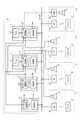
図1は、この発明が適用されるオーディオシステムの構成を示す図である。この種のオーディオネットワークシステムは、カスタムインストレーションと呼ばれ大型の戸建て住宅に施工されるものである。
<< Overview of Audio Network and Invention >>
FIG. 1 is a diagram showing the configuration of an audio system to which the present invention is applied. This type of audio network system is called a custom installation and is installed in a large detached house.
複数のオーディオ機器で構成されるオーディオ機器群10は、たとえばリビングルームの壁に設けられたラックに収納される。オーディオ機器群10として、AVレシーバ(AV receiver)11、12や、AVレシーバ11、12にオーディオソースを供給するDVDプレイヤ(DVD player)13、パーソナルコンピュータ(PC)14等のソース機器がある。AVレシーバ11、12DVDプレイヤ13等のオーディオ機器は、オーディオ信号を再生、増幅等処理するオーディオ回路部11A、12A、13A、機器の動作を制御する制御部11B、12B、13Bを備えている。また、AVレシーバ11、12は、ソース機器としてFM/AM放送を受信するチューナ(Tuner)11C、12Cを内蔵している。なお、PC14は、ハードディスクにオーディオファイルを記憶しこれをCPUが再生するため、ハードウェア的には制御部と区別がないが、PC14のオーディオ再生機能部をオーディオ回路部14A、制御機能部を制御部14Bと呼ぶ。
このように、オーディオ機器群10を構成するオーディオ機器の構成は任意であり、上記に限定されない。図示以外のソース機器としては、マイクロHDDドライブを内蔵したオーディオ再生装置やPC等がある。
The
As described above, the configuration of the audio devices constituting the
AVレシーバ11は、入力側に上記のDVDプレイヤ13、PC14等のソース機器を接続し、複数のソース機器のいずれかから入力したオーディオ信号を3つのゾーン(部屋)に供給する。各ゾーンに独立してオーディオ信号を供給するために、AVレシーバ11は3系統のオーディオアンプを有している。また、AVレシーバ12は、入力側に上記のDVDプレイヤ13、PC14等のソース機器を接続し、複数のソース機器のいずれかから入力したオーディオ信号を1つのゾーン(部屋)に供給する。このAVレシーバ12は、パワーアンプを備えておらず、オーディオ信号を光ファイバ等を介して担当ゾーンのアンプ23に送信する。
The
4つのゾーンZ1〜4は、それぞれ家屋内の部屋であり、たとえばゾーン1(Z1)が居間(Livng)、ゾーン2(Z2)が寝室(Bed Room)、ゾーン3(Z3)が子供部屋(Kids Room)、ゾーン4(Z4)が台所(Kitchen)である。ゾーン1〜4には、スピーカ21と無線LANのアクセスポイント22が設置されている。また、ゾーン4には、さらにアンプ23が設置されている。ゾーン1〜3のスピーカ21には、AVレシーバ11によって電力増幅されたオーディオ信号が印加される。また、ゾーン4においては、アンプ23がAVレシーバ12の赤外線オーディオ信号を受信して、この信号を電力増幅しスピーカ21に印加する。
Each of the four zones Z1 to 4 is a room in the house. For example, zone 1 (Z1) is a living room (Living), zone 2 (Z2) is a bedroom (Bed Room), and zone 3 (Z3) is a children's room (Kids). Room), Zone 4 (Z4) is the kitchen. In zones 1 to 4, a
各オーディオ機器の制御部11B,12B,13B,14Bおよびアクセスポイント22はLAN15で相互に接続されている。LAN15は、図示しないルータによってインターネットに接続されているが、各機器(制御11B,12B,13B、14Bおよびアクセスポイント22、コマンダ16)は、LAN15に接続されたとき、ローカルIPアドレスが付与され、各機器はそのローカルIPアドレスを用いて相互にアクセス可能である。制御機器であるコマンダ16は、LAN15上を検索して被制御機器であるオーディオ機器を検出し、そのIPアドレスを取得する。以後、このIPアドレスを用いて各オーディオ機器と交信する。LAN15は有線LAN、無線LAN、有線LANと無線LANの複合のいずれの形態であってもよい。
The
この発明の実施形態であるコマンダ(リモコン)16は、無線LANによりアクセスポイント22を介して各オーディオ機器の制御部11B,12B,13B,14Bと通信する。なお、この図では、コマンダ16は1台あり、この1台のコマンダ16が4つのゾーンで移動させて使用される形態を示しているが、コマンダ16がそれぞれのゾーンにあるような形態であってもよい。
The commander (remote controller) 16 according to the embodiment of the present invention communicates with the
以上の構成のオーディオシステムにおいて、利用者はコマンダ16を用いて自分が居るゾーンでオーディオ機器を制御して所望の音楽を聴くことができる。コマンダ16は、LAN15を介して被制御機器であるオーディオ機器11〜14からコマンドリストを含む自己記述ファイルを受信し、各コマンドをハードスイッチであるキースイッチ41〜56(図2参照)やディスプレイ36(図2参照)に表示されるメニューに割り当て、キースイッチ41〜56のオン操作またはメニューの選択に応じてオーディオ機器11〜14に対してコマンドを発行(送信)する。したがって、1台のコマンダ16で全てのオーディオ機器11〜14を制御することができる。
In the audio system configured as described above, the user can listen to desired music by using the
≪コマンダおよびオーディオ機器の説明≫
図2はコマンダ16の外観図である。また、図3はコマンダ16のブロック図である。
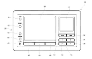
コマンダ16は略ハガキ大の平面形状を有する薄い直方体形状を成しており、その上面が操作面である。図2は、その操作面を示す平面図である。中央部やや左に液晶のディスプレイ36が設けられている。このディスプレイ36の右側上部にタッチパッド37が設けられている。タッチパッド37は、ディスプレイ36上のカーソルを移動させたり、カーソルが指しているオブジェクトを選択したりするためのデバイスである。利用者が指先で触れ、その指先を移動させることによりカーソルが移動する。また、使用者が指先が軽く叩くことにより、カーソルが指しているオブジェクトが選択される。
≪Description of commander and audio equipment≫
FIG. 2 is an external view of the
The
また、操作面の左辺から下辺にかけてキースイッチ群35が設けられている。キースイッチ群35は、16のキースイッチ41〜56からなっている。操作面の左辺沿いには、ゾーン選択キー41、入力選択キー42、音量アップ/ダウンキー43、44、およびミュートスイッチ45が設けられている。ゾーン選択キー41は、図1に示した4つのゾーンZ1〜Z4の選択画面を表示させるためのキースイッチである。入力選択キー42は、選択されているゾーンで再生するソース機器の選択画面を表示させるためのキースイッチである。音量アップ/ダウンキー43、44およびミュートスイッチ45は、選択されているソース機器で現在再生されているコンテンツ(たとえばオーディオ)の再生音量を上下させたり一時的に消音させるためのキースイッチである。
A
ディスプレイ36の下辺に沿って3つのファンクションキー47、48、49が設けられている。ファンクションキー47、48、49は、操作段階に応じて種々の機能が割り当てられる。
Three
タッチパッド37の下方には、バックキー51、ホームキー52および種々の再生制御キー53〜56が設けられている。バックキー51は、ディスプレイ36に表示させる画面を直前のものに戻すためのキースイッチである。また、ホームキー52は、ディスプレイ36に表示させる画面を初期画面に切り換えるキースイッチである。再生制御キー53〜56は、スタートキー53、ストップキー54、巻き戻しキー55、早送り(スキップ)キー56からなっている。
Below the
図3において、コマンダ16は、CPU31、ROM32、RAM33を有するとともに、無線LANコントローラ34、キースイッチ群35、ディスプレイ36、タッチパッド37を有しており、これらはバスを介して相互に接続されている。ROM32にはこのコマンダ16を制御するためのプログラム等が記憶されている。無線LAN制御部34は、アクセスポイント22を介して被制御機器であるオーディオ機器11〜14と通信し、自己記述ファイルや演奏情報等を受信する。RAM33には、無線LANコントローラ34が受信したオーディオ機器11〜14の自己記述ファイル、演奏情報が記憶される。
In FIG. 3, the
CPU31は、RAM33に記憶された被制御機器の自己記述ファイルに基づき、自装置をその被制御機器を制御するコマンダとしてセットアップする。自己記述ファイル中の「既知の機能」を各機能が割り当てられているキースイッチ群35の各キースイッチ41〜56に対応づけ、それ以外のキースイッチの割り当てがない機能(未知の機能)は、ディスプレイ36に階層化メニューとして表示し、最下層のメニュー項目にコマンドを対応づける。
Based on the self-describing file of the controlled device stored in the RAM 33, the CPU 31 sets up the own device as a commander for controlling the controlled device. The “known functions” in the self-describing file are associated with the
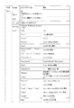
図4は、オーディオ機器11〜14のブロック図である。オーディオ機器11〜14は、オーディオ回路部69(11A,12A,13A,14Aに対応)に独自の構成を有するが、制御部60(11B,12B,13B,14Bに対応)の構成はほぼ同様である。制御部60は、CPU61、不揮発性メモリ62、RAM63、LANコントローラ64、操作部65、インタフェース66が相互にバスで接続された構成をしている。不揮発性メモリ62には自己記述ファイルが記憶されている。RAM63には、演奏中のアーティスト名、アルバム名、曲名等の演奏情報が記憶される。LANコントローラ64は、LAN15を介する他の機器(たとえばコマンダ16)と通信する。CPU61は、操作部65の操作やLANコントローラ64が受信した制御コマンドに基づいてオーディオ回路部69の動作を制御する。また、インタフェース66を介してオーディオ回路部69から演奏情報を受け取りRAM63に書き込む。さらに、CPU61は、制御部60をhttpサーバとして機能させ、コマンダ16がhttpのGETメソッドで不揮発性メモリ62上の自己記述ファイルやRAM63上の演奏情報を取得できるようにしている。
FIG. 4 is a block diagram of the
≪自己記述ファイルの説明≫
自己記述ファイルは、コマンダ16が、被制御機器であるオーディオ機器11〜14を制御可能にするために、オーディオ機器11〜14からコマンダ16に送信されるファイルである。コマンダ16は、自己記述ファイルを受信することにより、少なくとも、そのオーディオ機器の電源(オン/オフ、スリープ設定)、音量(音量レベル、ミュートのオン/オフ)、入力切換(接続されている各種ソース機器の選択)、再生制御(プレイ、ポーズ、ストップなど)、再生情報表示(アーチスト、アルバム名、曲名)、コンテンツブラウズ(コンテンツリスト表示、カーソル操作など)などの制御が可能になる。なお、ここに掲げた機能を「既知の機能」と呼ぶ。
≪Description of self-description file≫
The self-describing file is a file transmitted from the
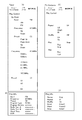
図5は自己記述ファイルの例を示す図である。自己記述ファイルは、被制御機器であるオーディオ機器11〜14の不揮発性メモリ(ハードディスクやフラッシュメモリ)に記憶され、LAN15上に公開されている。コマンダ16は、そのディレクトリにアクセスすることによって、自由に自己記述ファイルを取り出すことができる。
FIG. 5 shows an example of a self-describing file. The self-describing file is stored in a non-volatile memory (hard disk or flash memory) of the
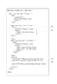
図5に自己記述ファイルの記述例を示す。同図に示すように自己記述ファイル(Unit Description)は、構造化言語(XML言語)で記述されている。メニュー構造の記述にはMenuタグ<Menu>が用いられる。このMenuタグをネスト(入れ子)させることにより、階層化メニューが表現される。 FIG. 5 shows a description example of the self-describing file. As shown in the figure, the self-description file (Unit Description) is described in a structured language (XML language). A Menu tag <Menu> is used to describe the menu structure. A nested menu is expressed by nesting the Menu tags.
Menuタグ<Menu>は、上記のように自己記述ファイルにおける階層化メニュー記述の基本となるタグであり、タグ内部に複数の属性が記述される。すなわち、Menuタグでメニューの階層構造を構築しながら、属性によりメニューの制御対象や表示形態等の種々の補足情報が付与される。Menuタグ内に記述される属性としては、Title_x属性、Icon属性、List_Type属性、YNC_Tag属性、Func属性などがある。 The Menu tag <Menu> is a tag that is the basis of the hierarchical menu description in the self-describing file as described above, and a plurality of attributes are described inside the tag. That is, various supplementary information such as a menu control target and a display form are given by an attribute while constructing a menu hierarchical structure with a Menu tag. Attributes described in the Menu tag include a Title_x attribute, an Icon attribute, a List_Type attribute, a YNC_Tag attribute, and a Func attribute.
たとえば、図5のMenuタグ101には、属性およびその値として、Func=”Subunit”、Title_1=”Main Zone”およびYNC_Tag=”Main_Zone”が記述され、Menuタグ102には、属性およびその値として、Func=”Vol”、Title_1=”Volume”"およびIcon=”xxxx/yyyy.png”が記述されている。
For example, Func = “Subunit”, Title_1 = “Main Zone”, and YNC_Tag = “Main_Zone” are described in the
Title_x属性は、このMenuタグの制御対象機器/機能の名称を表す属性である。1つのMenuタグが複数の言語の表記を想定して複数の名称の属性を持つことがあるため、Title_xのxには1から順の数値が設定される。 The Title_x attribute is an attribute representing the name of the control target device / function of this Menu tag. Since one Menu tag may have a plurality of name attributes assuming a notation in a plurality of languages, a numerical value starting from 1 is set in x of Title_x.
Icon属性は、このMenuタグの制御対象機器/機能のアイコンを指定する属性である。Icon属性は、このメニュー項目のディスプレイ36への表示形態としてアイコンが用いられるとき記述される属性である。アイコンの指定は、ファイル名とそのファイルのパス名によって記載される。たとえば、「Icon="icon/listen.png"」等である。記述されるパスは被制御機器に搭載されるhttpサーバのルートからのパスなので、ここに、その被制御機器のIPアドレスを付加し、httpのGETメソッドでアクセスすることでアイコンの画像ファイルを取得する。上記の「Icon="icon/listen.png"」の例の場合、「GET http://192.168.0.1/icon/listen.png」でアイコンの画像ファイルが取得される。なお、このURL、ファイル名等は一例でありこれに限定されない。
The Icon attribute is an attribute that specifies an icon of a control target device / function of this Menu tag. The Icon attribute is an attribute described when an icon is used as a display form of the menu item on the
List_Type属性は、このMenuタグの1つ下の階層のメニューを表示するときに推奨されるリスト形式を記述する属性である。属性値(リスト形式)には、Menu、Icon、Slider、10Keyなどがある。属性値がMenuのとき、通常のリスト表示によるメニュー形式が推奨される。なおこのMenu形式はデフォルトであるため省略可である。属性値がIconのとき、アイコンを用いたメニュー形式が推奨される。このIconが推奨される場合、1つ下の階層のメニュー項目には必ずIcon属性によりアイコンのパスが記述される。属性値がSliderのとき、下層のメニュー項目は数値のメニュー項目であり、スライダによる入力を前提としたメニュー構築が推奨される。また、属性値が10Keyのとき、下層のメニュー項目は数値のメニュー項目であり、テンキー入力によるメニュー構築が推奨される。なお、都合により(ハードウェア・ソフトウェア等の事情で)推奨形式でのメニュー構築・表示が不可能な場合、デフォルトのMenu形式のメニュー表示が行われる。 The List_Type attribute is an attribute that describes a list format recommended when displaying a menu in a hierarchy one level below this Menu tag. The attribute value (list format) includes Menu, Icon, Slider, 10Key, and the like. When the attribute value is Menu, a normal list display menu format is recommended. The Menu format is a default and can be omitted. When the attribute value is Icon, a menu format using icons is recommended. When this Icon is recommended, the icon path is always described by the Icon attribute in the menu item one level below. When the attribute value is Slider, the menu item in the lower layer is a numerical menu item, and it is recommended to construct a menu that assumes input by a slider. When the attribute value is 10 Key, the lower-level menu items are numerical menu items, and it is recommended to construct a menu by numeric keypad input. If it is not possible to construct and display a menu in the recommended format for convenience (due to hardware, software, etc.), a default menu format menu is displayed.
YNC_Tag属性は、制御対象ゾーンまたは制御対象機器の名称が記述される属性である。この属性が記述されたMenuタグ以下の記述は、この属性の名称を有するゾーンまたはソース機器に関する記述である事を示す。Func属性は、制御対象機能を表す属性である。Func属性の値は、他種類にわたり階層化されている。図6にMenuタグのFunc属性の値の例を示しておく。 The YNC_Tag attribute is an attribute in which the name of the control target zone or the control target device is described. The description below the Menu tag in which this attribute is described indicates that the description is related to the zone or source device having the name of this attribute. The Func attribute is an attribute that represents a control target function. The value of the Func attribute is hierarchized over other types. FIG. 6 shows an example of the value of the Func attribute of the Menu tag.
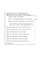
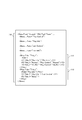
図7は、自己記述ファイルの記述のうち、最下層メニューの記述の一部を示す図である。また、図8は、この自己記述ファイルのMenuタグ中のTitle_x属性を書き出して構成したメニューの例を示す図である。この最下層メニューは、たとえば図5のMenuタグ102の最下層として記述されるものである。最下層メニューでは、利用者の操作に応じたコマンドを発行するためにMenuタグのほか、Cmdタグ<Cmd>、Cmd_List<Cmd_List>タグ、Param_xタグ<Param_x>等のタグを用いた記述が行われている。
FIG. 7 is a diagram showing a part of the description of the lowest menu among the descriptions of the self-description file. FIG. 8 is a diagram showing an example of a menu configured by writing the Title_x attribute in the Menu tag of the self-describing file. This bottom layer menu is described as the bottom layer of the
Cmdタグは、コマンド発行を指示するタグであり、発行されるコマンド(この例ではPUTコマンド)のIDが記述される。
図7に示すように、Cmdタグ要素105には必ず“Param_x”という文字列が記述され、これと同名のタグであるParam_xタグがCmdタグに引き続いて記述される。このParam_xタグ要素106にメニューの最下位項目として選択可能なパラメータが記述される。なお、Param_xタグは、複数記述されることがあるため識別のためxには1から順の数字を設定される。Param_xタグの下層には以下のタグが少なくとも1つ配置される。
The Cmd tag is a tag for instructing command issuance, and describes the ID of the issued command (PUT command in this example).
As shown in FIG. 7, a character string “Param_x” is always described in the
Directタグ<Direct>は、パラメータを直接記述する場合に用いられるタグであり、開始タグに続いてパラメータの文字列が記述される。Directタグは、Param_xタグの領域内に必要数記述される。図7のMute制御では、Directタグで「On」、「Off」の2つのパラメータが記述されている。また、Drectタグには、Title_x属性やIcon属性を伴う場合がある。Title_x属性は、そのパラメータの名称を表す属性であり、Iconタグは、そのパラメータ(制御内容)をメニュー項目としてディスプレイ36に表示するときアイコンとして表示する場合のアイコン画像を指定する属性である。
The Direct tag <Direct> is a tag used when a parameter is directly described, and a parameter character string is described following the start tag. The required number of Direct tags is described in the Param_x tag area. In the mute control in FIG. 7, two parameters “On” and “Off” are described in the Direct tag. In addition, the Direct tag may be accompanied by a Title_x attribute or an Icon attribute. The Title_x attribute is an attribute that represents the name of the parameter, and the Icon tag is an attribute that specifies an icon image when the parameter (control content) is displayed as an icon when the parameter is displayed on the
Rangeタグ<Range>は、パラメータの範囲とステップを記述するとき用いられるタグであり、「<開始値>,<終了値>,<ステップ>」の形式で記述される。メニューには、開始値から終了値までの間のステップ刻みの数値リストが表示される。図7の音量Level制御では、開始値=−80.5dB、終了値=16.5dB、ステップ=0.5dBとなっており、メニューには、−80.5dB〜16.5dBまでの間の0.5dB刻みのゲイン値がメニュー項目としてリスト表示される。
また、これ以外にも、Textタグ<Text>(パラメータの文字数範囲と文字タイプを記述するためのタグ)、Indirectタグ<Indirect>(パラメータをGETコマンドで取得する場合のタグ)がある。
The Range tag <Range> is a tag used when describing a parameter range and step, and is described in the format of “<start value>, <end value>, <step>”. The menu displays a list of numerical values in steps from the start value to the end value. In the volume level control in FIG. 7, the start value = −80.5 dB, the end value = 16.5 dB, and the step = 0.5 dB, and the menu includes 0 to −80.5 dB to 16.5 dB. Gain values in increments of .5 dB are listed as menu items.
In addition, there are a Text tag <Text> (a tag for describing the character number range and character type of the parameter) and an Indirect tag <Indirect> (a tag for acquiring a parameter with the GET command).
コマンダ16においては、ミュートのオン/オフをキースイッチ(ミュートキー)45に割り当て、−80.5dB〜16.5dBの音量制御をキースイッチ(音量アップ/ダウンキー)43,44に割り当てている。
ミュートキー45はトグル動作であるため、ミュートオン/オフの機能をミュートキー45に割り当てるときGETコマンドで被制御機器(メインゾーン)のミュートオン/オフの状態を取得する。その後ミュートキー45がオンされると、そのときの状態と反対の状態を設定するためのコマンドを発行する。
ミュートオンのコマンドは、たとえば「Main_Zone,Vol_Control,Mute,On」の文字列をXML形式に変換したものである。
また、音量アップ/ダウンキー43,44は現在値から1ステップ増加/減少を指示するキースイッチであるため、音量制御の機能を音量アップ/ダウンキー43,44に割り当てるときGETコマンドで被制御機器の音量レベル値を取得する。その後音量アップ/ダウンキー43,44がオンされると、そのときの音量値から1ステップ増加/減少させた音量レベル値をパラメータとするコマンドを発行する。
音量レベル制御のコマンドは、たとえば「Main_Zone,Vol_Control,Level,-25.0」の文字列をXML形式に変換したものである。
In the
Since the
The mute-on command is obtained, for example, by converting a character string “Main_Zone, Vol_Control, Mute, On” into an XML format.
Further, the volume up / down
The volume level control command is obtained by converting, for example, a character string “Main_Zone, Vol_Control, Level, −25.0” into an XML format.
ここで、GETコマンドとは、GETタグによって発行されるコマンドであり、被制御機器から何らかの情報を得るときに発行される。 Here, the GET command is a command issued by a GET tag, and is issued when obtaining some information from the controlled device.
図7に示しているCmd_Listタグ<Cmd_List>には、実際に発行されるコマンドが記述される。Cmd_Listタグは、Menuタグのうち、Func=”Subunit”またはFunc=”Source_Device”属性毎に1つだけ記述される。記述位置は、そのタグの1階層下の末尾となり、影響範囲はそのタグ以下全体となる。 The Cmd_List tag <Cmd_List> shown in FIG. 7 describes commands that are actually issued. Of the Menu tags, only one Cmd_List tag is described for each Func = “Subunit” or Func = “Source_Device” attribute. The description position is the end of the tag one layer below, and the affected range is the entire tag and below.
Cmd_Listタグ要素107内の下の階層には必ずDefineタグ<Define>が1または複数配置される。Defineタグ108は、必ずID属性を伴い、このID属性によって、以下に記述されるコマンドが特定される。上述したように、Cmdタグ側では、このIDを指定する事で発行するコマンドが指定される。
One or more Define tags <Define> are always arranged in the lower hierarchy in the
図7に示すように、Defineタグは、Cmd_Listタグ要素107に少なくとも1個、通常は複数記述され、それぞれIDで識別されるコマンド(コマンド本体)が記述される。なお、コマンドはコンマ区切りで記述され、発行時はXML形式に変換される。
As shown in FIG. 7, at least one Define tag is normally described in the
このように、階層化されたメニューの最下層にはコマンドを発行するための記述があり、実際に発行されるコマンドはCmd_Listの領域内に記載され、Cmdタグの属性で指定されたコマンド本体とCmdタグの領域内に記載されるパラメータの組み合わせからなっている。一般的に1つのコマンド本体には複数の(場合によっては多数の)パラメータが付属するため、1つのコマンド本体で多種類のコマンドの発行が可能になる。 As described above, there is a description for issuing a command at the lowest layer of the hierarchical menu, and the actually issued command is described in the Cmd_List area, and the command body specified by the attribute of the Cmd tag and It consists of a combination of parameters described in the Cmd tag area. In general, since one command body is accompanied by a plurality of parameters (in some cases, a large number), a single command body can issue various types of commands.
また、図9は、自己記述ファイルの他の一部であり、FKeyタグ<FKey>が記述されている箇所の示す図である。 FIG. 9 shows another part of the self-describing file and a part where the FKey tag <FKey> is described.
FKeyタグは、特定の機能をファンクションキー47、48、49に割り当てる際に用いられるタグである。FKeyタグは、Func="Subunit"またはFunc="Source_Device"属性を有するMenuタグ毎に記述される。記述位置は、同属性を有するMenuタグの1階層下の末尾となり、影響範囲はそのMenuタグ以下全体となる。
The FKey tag is a tag used when assigning a specific function to the
FKeyタグの下の階層には以下のタグが配置される。
Pathタグ<Path>は、FKeyタグによるファンクションキー47、48、49への機能割り当ての有効範囲(パス)を記述するためのタグである。パスは、Fkeyタグの階層からの相対パスで表現される。なお、このPathタグが空タグならば、Pathタグが属するMenuタグの範囲全体を示している。
The following tags are arranged in the hierarchy below the FKey tag.
The Path tag <Path> is a tag for describing an effective range (path) of function assignment to the
F1タグ<F1>は、ファンクションキー47(F1キー)に割り当てる機能すなわちメニュー項目のショートカットパスを記述するためのタグである。F2タグ<F2>は、ファンクションキー48(F2キー)に割り当てる機能すなわちメニュー項目のショートカットパスを記述するためのタグである。F3タグ<F3>は、ファンクションキー49(F3キー)に割り当てる機能すなわちメニュー項目のショートカットパスを記述するためのタグである。パスは、Fkeyタグの階層からの相対パスで表現され、その記述形式は、ダブルクォート「"」で囲まれ、コンマで区切られている。F1,F2またはF3タグが、空F1,F2またはF3タグが、記述されなかった場合、そのタグに対応するファンクションキーに機能(パス)を割り当てないこと表すものとする。 The F1 tag <F1> is a tag for describing a function assigned to the function key 47 (F1 key), that is, a shortcut path of a menu item. The F2 tag <F2> is a tag for describing a function assigned to the function key 48 (F2 key), that is, a shortcut path of a menu item. The F3 tag <F3> is a tag for describing a function assigned to the function key 49 (F3 key), that is, a shortcut path of a menu item. The path is expressed as a relative path from the hierarchy of the Fkey tag, and the description format is surrounded by double quotes ““ ”and separated by commas. When the F1, F2 or F3 tag is not described, and the empty F1, F2 or F3 tag is not described, it is assumed that the function (path) is not assigned to the function key corresponding to the tag.
また、FKeyタグは、Func="Subunit"またはFunc="Source_Device"属性を有するMenuタグ毎に複数記述することができる。各FKeyタグは、Pathタグに記述された範囲で有効であり、複数のFKeyタグの範囲が重なっている領域は、後に記述されているFKeyタグが有効となる。 A plurality of FKey tags can be described for each Menu tag having the Func = "Subunit" or Func = "Source_Device" attribute. Each FKey tag is effective in the range described in the Path tag, and the FKey tag described later is effective in an area where the ranges of a plurality of FKey tags overlap.
図9の場合、FKeyタグの記述111は、Pathタグが空タグであるため、Menuタグの記述110全体を有効範囲としているが、その後に記述されているFKeyタグの記述112は、Pathタグで"Play Info"を有効範囲としているため、後の記述111のPathタグの記述が有効となり、記述111は"Play Info"に適用され、記述110は、"Play Info"以外のMenuタグ領域に適用される。
In the case of FIG. 9, the
記述110によれば、F1キー(ファンクションキー47)には、ディスプレイ36に演奏情報"Play Info"を表示させる機能が割り当てられ、F2キー(ファンクションキー48)には、演奏を繰り返させる"Repeat"機能が割り当てられ、F3キー(ファンクションキー49)には、曲順をランダムに演奏させる"Shuffle"機能が割り当てられる。
According to the
また、記述111によれば、"Play Info"の表示中に、F1キー(ファンクションキー47)には、ディスプレイ36にプレイリスト表示して演奏曲を調整する"List Control"機能が割り当てられ、F2キー(ファンクションキー48)には、ルートパスであるメニューをディスプレイ36に表示させる機能が割り当てられ、F3キー(ファンクションキー49)には機能が割り当てられない。
Further, according to the
≪階層化メニューの説明≫
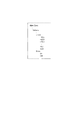
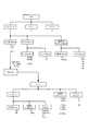
上に説明した自己記述ファイルで表現される階層化メニューの一部を図示すると図10のようになる。メインゾーン(Main Zone)の下位に入力選択(Input)、音量制御(Volume)、電源制御(Power Control)のメニューがツリー状に配置されている。音量制御の下位には、音量レベル制御(Level)、ミュート制御(Mute)メニューがツリー状に配置されている。また、電源制御の下位には、電源オン/オフ制御(Power)、スリープ設定(Sleep)のメニューがツリー状に配置されている。各ツリーの最下位のメニュー項目には複数のパラメータが準備されており、利用者の操作内容およびそのときの被制御機器の状態に応じたパラメータが選択される。そして、その最下位のメニュー項目のコマンド本体と選択されたパラメータが組み合わされてコマンドが構成され、被制御機器であるオーディオ機器に向けて発行(送信)される。
≪Explanation of hierarchical menu≫
A part of the hierarchical menu expressed by the self-description file described above is shown in FIG. Below the main zone (Main Zone), menus for input selection (Input), volume control (Volume), and power supply control (Power Control) are arranged in a tree shape. Below the volume control, volume level control (Level) and mute control (Mute) menus are arranged in a tree shape. In addition, under the power control, a menu of power on / off control (Power) and sleep setting (Sleep) is arranged in a tree shape. A plurality of parameters are prepared for the menu item at the lowest level of each tree, and a parameter corresponding to the user's operation content and the state of the controlled device at that time is selected. Then, the command body of the lowest menu item and the selected parameter are combined to form a command, which is issued (transmitted) to the audio device that is the controlled device.
各メニュー項目に対して以下のようなパラメータが準備されている。メニュー項目の入力選択(Input)に対しては、Tuner、DVD、・・、VCRの値が準備されている。各パラメータは、このAVレシーバに接続されているソース機器に対応している。メニュー項目の音量レベル制御(Level)には、−80.5dBから16.5dBまで0.5dB刻みの値が準備されている。メニュー項目のミュート制御(Mute)に対してはOn、Offの値が準備されている。メニュー項目の電源オン/オフ制御(Power)に対してはOn、Standbyの値が準備されている。また、メニュー項目のスリープ設定(Sleep)に対してはLast、120、90、60、30、Offの値が準備されている。各パラメータは、電源がオフされるまでの時間(分)に対応しており、Offはスリープ機能をオフして電源オンを継続させる設定、Lastは前回のスリープ設定をそのまま用いる設定に対応している。なお、上記パラメータのうち入力選択に関してはコマンドで取得してXMLに動的にマージ(間接マージ)することもできる。 The following parameters are prepared for each menu item. For menu item input selection (Input), Tuner, DVD,..., VCR values are prepared. Each parameter corresponds to a source device connected to the AV receiver. For the volume level control (Level) of the menu item, values in increments of 0.5 dB from -80.5 dB to 16.5 dB are prepared. On and Off values are prepared for the menu item mute control (Mute). On and standby values are prepared for the power on / off control (Power) of the menu item. For the menu item sleep setting (Sleep), the values of Last, 120, 90, 60, 30, and Off are prepared. Each parameter corresponds to the time (minutes) until the power is turned off, Off is a setting for turning off the sleep function and continuing the power on, and Last is a setting for using the previous sleep setting as it is. Yes. Of the above parameters, regarding input selection, it can be acquired by a command and dynamically merged into XML (indirect merging).
上記構造の階層化メニューを、階層ごとにディスプレイ36に表示すれば、メニューツリーを辿っていく操作で被制御機器の全ての機能を制御することができる。ただし、上述した「既知の機能」の制御は、キースイッチ41〜56に割り当てられ、階層化メニューを辿らなくてもキースイッチ41〜56のいずれかを操作することにより、即座に直接的に制御できるようになっている。そして、キースイッチ41〜56に割り当てられた「既知の機能」は、ディスプレイ36に表示される階層化メニューから削除され、階層化メニューの簡素化を実現している。
If the hierarchical menu having the above structure is displayed on the
ここで、「既知の機能」とは「自己記述ファイルの説明」の冒頭に示した機能群であり、電源オン/オフやプレイスタート/ストップ等のどの機器にも適用されるような一般的・汎用的な機能のことである。既知の機能のコマンドを発行するMenuタグには、どの被制御機器の自己記述ファイルにおいても同一の統一されたTitle_x属性が与えられている。一方、コマンダ16のROM32には各キースイッチ41〜56に割り当てる機能の名称(Title)が記憶されている。CPU31はROM32に記憶しているTille_xとMenuタグのTitle_x属性とを対比し、対応する機能のコマンドを各キースイッチ41〜56に割り当てる。
Here, “known functions” is a group of functions shown at the beginning of “Explanation of self-description file”, and is generally applied to any devices such as power on / off and play start / stop. It is a general-purpose function. The Menu tag that issues a command of a known function is given the same unified Title_x attribute in the self-description file of any controlled device. On the other hand, the ROM 32 of the
図10はオーディオ機器の一つであるAVレシーバ11の自己記述ファイルの最上位の一部を示したものであるが、AVレシーバ11以外のオーディオ機器の階層化メニューの一例を図11に示しておく。なお、この図でPlayInfoは、階層化メニューではなく、GET機能で取得することができる被制御機器の動作状態データである。
FIG. 10 shows a part of the highest level of the self-describing file of the
図10の階層化メニューでは、メニュー項目Inputが最下層であり、ソース機器が選択されたときコマンドを発行してメニューツリーが終了する。ただし、本実施形態のコマンダ16は、メニュー項目Inputでソース機器が選択されると、その選択されたソース機器から自己記述ファイルを受信して、そのソース機器のメニュー項目に制御をジャンプさせる。
In the hierarchical menu of FIG. 10, the menu item Input is the lowest layer, and when a source device is selected, a command is issued and the menu tree is terminated. However, when a source device is selected by the menu item Input, the
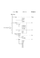
図12は、AVレシーバ(メインゾーン)の階層化メニューとソース機器(tuner)の階層化メニューとのリンク形態を示す図である。メインゾーンのメニュー項目Inputでチューナ13が選択された場合、コマンダ16はAVレシーバ11の制御部11Bから取得した自己記述ファイルを解析して内蔵のチューナ11Cの演奏情報(図11(B)参照))を取得し、この演奏情報をディスプレイ36に表示する。こののち、メニュー表示(制御対象)をチューナ11Cにジャンプさせる(図11(A)参照)。
FIG. 12 is a diagram showing a link form between the hierarchical menu of the AV receiver (main zone) and the hierarchical menu of the source device (tuner). When the
一方、メニュー項目Inputで外部のソース機器、たとえばPC14が選択された場合、コマンダ16はPC14の制御部14Bにアクセスして、演奏情報(図11(D)参照)を取得し、このソース機器の現在の動作状態をディスプレイ36に表示する。こののち、PC14の制御部14Bから自己記述ファイルを取得してPC14の音楽再生機能を制御するメニューを表示して(図11(C)参照)、PC14用のコマンダとして自己をセットアップする。
On the other hand, when an external source device such as the
このように、複数の被制御機器で、階層化メニューをリンクさせていることにより、複数の機器間で関連するメニュー項目を操作する場合に利用者の操作性を向上させることができる。 Thus, by linking the hierarchical menu with a plurality of controlled devices, it is possible to improve the operability of the user when operating related menu items between the plurality of devices.
≪コマンダの動作の説明≫
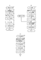
図13のフローチャート、図14のディスプレイ36の表示例を参照して、コマンダ16の動作を説明する。
まず、図13(A)はゾーン選択キー41がオンされたときの動作を示すフローチャートである。利用者がいずれかのゾーン(部屋)内でコマンダ16を操作するとき、最初にゾーン選択キー41をオンする。ゾーン選択キー41がオンされると(S1)、アクセスポイント22を経由してLAN15にアクセスし、通信可能なオーディオ機器を検索する(S2)。発見したオーディオ機器のなかから、AVレシーバを全て選択し、選択されたAVレシーバの自己記述ファイルおよび演奏情報を取得する(S3)。取得した自己記述ファイルおよび演奏情報に基づき、ゾーン構成および各ゾーンで演奏中の曲を割り出す(S4)。各ゾーンのアイコンをそのゾーンを担当するAVレシーバから取得してメニュー画面を編集する(S5)。そしてこの画面をゾーン選択画面(図14(A))として表示する(S6)。
≪Description of commander operation≫
The operation of the
First, FIG. 13A is a flowchart showing an operation when the
なお、自己記述ファイルの取得はhttpのGETメソッドで取得すればよい。たとえば「GET http://192.168.0.1/RemoteControl/UnitDesc.xml」などである。なおこのIPアドレスは例であり、実際には、各オーディオ機器のアドレスが指定される。また、アイコンの取得もhttpのGETメソッドで取得すればよい。たとえば「GET http://192.168.0.1/icon/listen.png」などである。なおこのIPアドレスは例であり、実際には、各オーディオ機器のアドレスが指定される。 The self-describing file may be acquired using the GET method of http. For example, “GET http://192.168.0.1/RemoteControl/UnitDesc.xml”. Note that this IP address is an example, and the address of each audio device is actually specified. In addition, the icon may be acquired using the GET method of http. For example, “GET http://192.168.0.1/icon/listen.png”. Note that this IP address is an example, and the address of each audio device is actually specified.
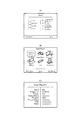
上記S6で表示されるゾーン選択画面の表示例を図14(A)に示す。この図では、左側に4つのゾーン(Living,Bed Room,Kids Room,Kitchen)が表示され、その右側に各ゾーンで演奏中の曲情報(曲名、歌手名)が表示されている。利用者は、タッチパッド37でカーソルを操作し、所望のゾーンの位置でクリックすることにより、そのゾーンを選択することができる。通常、利用者は自分が居るゾーン(部屋)を選択する。
A display example of the zone selection screen displayed in S6 is shown in FIG. In this figure, four zones (Living, Bed Room, Kids Room, and Kitchen) are displayed on the left side, and music information (song name and singer name) being played in each zone is displayed on the right side. The user can select the zone by operating the cursor with the
上記ゾーンの選択が行われると、コマンダ16は、図13(B)の処理を実行する。
図13(B)において、ゾーンの選択が行われると(S10)、選択されたゾーンを担当するAVレシーバと通信して自己記述ファイルを受信する(S11)。なお、S3で受信した自己記述ファイルを保存していれば、S11の再度自己記述ファイル取得処理は不要である。受信した自己記述ファイルに含まれるメニュー項目のうち、上述の「既知の機能」を制御するメニュー項目をキースイッチ41〜46、50〜56に割り当てるとともに、FKeyタグにより指定されたメニュー項目(ショートカット)をファンクションキー47〜49に割り当てる(S12)。次に上記キースイッチ41〜46、50〜56に割り当てられた「既知の機能」を除いて(未知の機能のみで)メニューツリーを再構築する(S13)。このとき、被制御機器であるAVレシーバから音量レベル値やミュートのオン/オフなどの動作状態を取得し、メニュー項目が選択されたとき、または、キースイッチ41〜56が操作されたときどのパラメータを用いてコマンドを発行するかを設定する(S14)。たとえば現在値がミュートOnであれば、ミュートキー45がオンされたときミュートOffのコマンドを発行するように設定する。そして、選択されたゾーンの最上位のメニューである入力選択画面を編集する(S15)。なお、このとき、入力選択画面はアイコンによるリスト表示形式が推奨されているため、選択されたゾーンを担当するAVレシーバにアクセスして各入力のソース機器のアイコンを取得する。取得したアイコンを用いた入力選択画面(図14(B))をディスプレイ36に表示する(S16)。
When the zone is selected, the
In FIG. 13B, when a zone is selected (S10), the self-description file is received by communicating with the AV receiver in charge of the selected zone (S11). If the self-describing file received in S3 is stored, the self-describing file acquisition process in S11 is unnecessary. Among the menu items included in the received self-describing file, the menu item for controlling the above-mentioned “known function” is assigned to the
なお、利用者によって入力選択キー(MUSICキー)が押下された場合には、既に自己記述ファイルの取得等の処理が終了しているため、S15の処理から実行される。 If the input selection key (MUSIC key) is pressed by the user, the process such as acquisition of the self-describing file has already been completed.
上記S15で表示される入力選択画面の例を図14(B)に示す。この図では、6個のソース機器(Net MusicService,Internet Radio,PC Contents,Bluetooth,USB,Silicon Audio)が選択可能になっている。利用者は、タッチパッド37でカーソルを操作し、所望のソース機器の位置でクリックすることにより、そのソース機器を選択することができる。
An example of the input selection screen displayed in S15 is shown in FIG. In this figure, six source devices (Net Music Service, Internet Radio, PC Contents, Bluetooth, USB, and Silicon Audio) can be selected. The user can select the source device by operating the cursor with the
利用者が、ディスプレイ36に表示されているソース機器のいずれかを選択すると、コマンダ16は、制御対象のオーディオ機器をその選択されたソース機器に切り換えて図13(C)の動作を実行する。なお、制御対象のオーディオ機器が自己記述ファイルを持たないものである場合、コマンダ16は、AVレシーバからそのオーディオ機器に関する記述ファイルを受信してもよく、また、AVレシーバ経由でそのオーディオ機器を制御するようにしてもよい。
When the user selects one of the source devices displayed on the
図14(B)に示した入力選択画面でソース機器が選択されると(S20)、選択されたソース機器と通信し、自己記述ファイルを受信するとともに演奏情報(Play Info)を取得する(S21)。そしてディスプレイ36に、図14(C)に示すようなPlay Info画面を表示するとともに(S22)、受信した自己記述ファイルに含まれるメニュー項目のうち既知の機能」を制御するメニュー項目をキースイッチ41〜46、50〜56に割り当てるとともに、FKeyタグにより指定されたメニュー項目(ショートカット)をファンクションキー47〜49に割り当てる(S23)。次に上記キースイッチ41〜46、50〜56に割り当てられた「既知の機能」を除いて(未知の機能のみで)メニューツリーを再構築する(S24)。同時に、被制御機器であるソース機器から動作状態を取得し、メニュー項目の選択やキースイッチのオンに対応してどのパラメータを用いてコマンドを発行するかを設定する(S25)。こののち、バンドや周波数のコントロールを可能にする。
なお、選択されたソース機器が、AVレシーバに内蔵のチューナであった場合、S21では新たに自己記述ファイル、演奏情報を取得する必要はなく、既に取得しているAVレシーバの自己記述ファイルからチューナに関する記述を解析して取り出せばよい。
When a source device is selected on the input selection screen shown in FIG. 14B (S20), it communicates with the selected source device, receives a self-describing file, and acquires performance information (Play Info) (S21). ). Then, a Play Info screen as shown in FIG. 14C is displayed on the display 36 (S22), and a menu item for controlling a “known function” among the menu items included in the received self-description file is displayed on the
When the selected source device is a tuner built in the AV receiver, it is not necessary to newly acquire a self-describing file and performance information in S21, and the tuner is already acquired from the self-describing file of the AV receiver. Analyze the description about and retrieve it.
このように上記実施形態では、−80.5dB〜16.5dBのパラメータを音量アップ/ダウンキー43,44に対応づけ、音量アップキー43がオンされた場合には、現在の音量値から1ステップ大きいパラメータでコマンドを生成するようにし、音量ダウンキー44がオンされた場合には、現在の音量値から1ステップ小さいパラメータでコマンドを発行するようにしている。これにより、コマンド本体に多数のパラメータが付属している場合でも、キースイッチまたはメニュー項目を簡略化することができる。
As described above, in the above embodiment, the parameter of −80.5 dB to 16.5 dB is associated with the volume up / down
なお、この逆も可能である。すなわち、コマンド本体に付属するパラメータがUP/DOWNであった場合に、コマンドで制御可能な範囲の全ての値(たとえば、1,2,…,9,10)をメニュー項目としてリスト表示し、目的の数値を選択することによるダイレクトな制御を可能にしてもよい。メニュー項目の表示形態は、たとえばプルダウンメニューのような形態を採用すればよい。 The reverse is also possible. That is, when the parameter attached to the command body is UP / DOWN, all values in the range controllable by the command (for example, 1, 2,. Direct control may be made possible by selecting these numerical values. For example, the menu item display form may be a pull-down menu.
以上の実施形態では、「既知の機能」をハードウェアであるキースイッチに対応づけて、階層化メニュー(メニューツリー)から削除しているが、必ずしも削除する必要はなく、「既知の機能」をキースイッチ、階層化メニューの両方で操作可能にしてもよい。 In the above embodiment, the “known function” is associated with the key switch that is hardware and deleted from the hierarchical menu (menu tree). However, the “known function” is not necessarily deleted. Operation may be performed using both the key switch and the hierarchical menu.
以上の実施形態では、コマンダ16は無線LANでネットワークに接続する構成になっているが、有線LANでネットワークに接続する構成であっても構わない。
また、この実施形態では各被制御機器とコマンダがネットワークを介して接続されるような形態になっているが、図15に示すように、各被制御機器とコマンダとがそれぞれ個別に通信する形態であっても本発明は適用可能である。
In the above embodiment, the
In this embodiment, each controlled device and the commander are connected via a network. However, as shown in FIG. 15, each controlled device and the commander individually communicate with each other. Even so, the present invention is applicable.
また、この実施形態では、本発明をオーディオシステムに適用し、被制御機器がオーディオ機器であるが、本発明はオーディオシステムに限らずあらゆる制御システムに適用することができ、被制御機器はオーディオ機器に限定されない。 In this embodiment, the present invention is applied to an audio system, and the controlled device is an audio device. However, the present invention can be applied not only to the audio system but also to any control system, and the controlled device is an audio device. It is not limited to.
10…オーディオ機器群(被制御機器群)
11,12…AVレシーバ
13…チューナ
14…DVDプレイヤ
16…コマンダ
36…ディスプレイ
37…タッチパッド
41〜56…キースイッチ
10 ... Audio device group (controlled device group)
DESCRIPTION OF
Claims (5)
複数の被制御機器から複数の機能制御コマンドを受信して機器毎に階層化し、
前記複数の機能制御コマンドが対応づけられた画像または文字を、前記機器毎に階層化された複数ページで前記ディスプレイに表示するとともに、上層の機器のページに下層の機器のページへの移動処理が対応づけられた画像または文字を表示し、
さらに、前記複数の機能制御コマンドのうち、最上層の機器の一部の機能制御コマンドを前記コマンドキーに対応づけ、前記ディスプレイの表示階層を移動させても、該コマンドキーに割り当てられた機能制御コマンドは変化させない制御部であって、
前記コマンドキーが操作されたとき、そのコマンドキーに対応づけられている機能制御コマンドを発行し、前記ポインティング操作部により前記ディスプレイに表示された画像または文字が指定されたとき、その画像または文字に対応づけられている機能制御コマンドを発行する制御部と、
を備えた遠隔制御装置。 A display, a pointing operation unit for accepting an operation for designating a predetermined position on the display, a hardware command key,
Stratified to each device receives a plurality of function control commands from a plurality of controlled devices,
The images or characters associated with the plurality of function control commands are displayed on the display in a plurality of pages hierarchized for each device, and a process of moving to the page of the lower device is performed on the upper device page. Display the associated image or text,
Furthermore, among the function control command of the multiple, associating a part of the function control command of the uppermost device to said command keys, by moving the display layer of the display, assigned to the command key function The control command is a control unit that does not change,
When the command key is operated, a function control command associated with the command key is issued, and when the image or character displayed on the display is designated by the pointing operation unit, the image or character is displayed. A control unit that issues the associated function control command; and
Remote control device with.
前記機能制御コマンドのうち、電源オン/オフを含む一般的または汎用的な機能である既知の機能を、前記コマンドキーに割り当て、
該既知の機能は、前記ディスプレイに表示される画像または文字に割り当てず、それ以外の未知の機能を、前記ディスプレイに表示される画像または文字に割り当てる
請求項1または請求項2に記載の遠隔制御装置。 The controller is
Of the function control commands, a known function that is a general or general function including power on / off is assigned to the command key,
The known functions are not assigned to images or characters displayed on the display, and other unknown functions are assigned to images or characters displayed on the display.
The remote control device according to claim 1 or 2.
少なくとも、前記遠隔制御装置と通信する通信手段、および、前記自己記述ファイルを記憶する記憶手段を備えた1または複数の被制御機器と、
で構成される遠隔制御システム。 A remote control device according to claim 4;
At least one communication device that communicates with the remote control device, and one or a plurality of controlled devices including a storage device that stores the self-describing file;
Remote control system consisting of.
Priority Applications (1)
| Application Number | Priority Date | Filing Date | Title |
|---|---|---|---|
| JP2008317724A JP5347472B2 (en) | 2008-12-12 | 2008-12-12 | Remote control device and remote control system |
Applications Claiming Priority (1)
| Application Number | Priority Date | Filing Date | Title |
|---|---|---|---|
| JP2008317724A JP5347472B2 (en) | 2008-12-12 | 2008-12-12 | Remote control device and remote control system |
Publications (2)
| Publication Number | Publication Date |
|---|---|
| JP2010141748A JP2010141748A (en) | 2010-06-24 |
| JP5347472B2 true JP5347472B2 (en) | 2013-11-20 |
Family
ID=42351446
Family Applications (1)
| Application Number | Title | Priority Date | Filing Date |
|---|---|---|---|
| JP2008317724A Expired - Fee Related JP5347472B2 (en) | 2008-12-12 | 2008-12-12 | Remote control device and remote control system |
Country Status (1)
| Country | Link |
|---|---|
| JP (1) | JP5347472B2 (en) |
Families Citing this family (81)
| Publication number | Priority date | Publication date | Assignee | Title |
|---|---|---|---|---|
| US9510055B2 (en) | 2013-01-23 | 2016-11-29 | Sonos, Inc. | System and method for a media experience social interface |
| US20150220498A1 (en) | 2014-02-05 | 2015-08-06 | Sonos, Inc. | Remote Creation of a Playback Queue for a Future Event |
| US9679054B2 (en) | 2014-03-05 | 2017-06-13 | Sonos, Inc. | Webpage media playback |
| US20150324552A1 (en) | 2014-05-12 | 2015-11-12 | Sonos, Inc. | Share Restriction for Media Items |
| US20150356084A1 (en) | 2014-06-05 | 2015-12-10 | Sonos, Inc. | Social Queue |
| US9874997B2 (en) | 2014-08-08 | 2018-01-23 | Sonos, Inc. | Social playback queues |
| WO2016049329A1 (en) | 2014-09-24 | 2016-03-31 | Sonos, Inc. | Social media queue |
| US10645130B2 (en) | 2014-09-24 | 2020-05-05 | Sonos, Inc. | Playback updates |
| US9690540B2 (en) | 2014-09-24 | 2017-06-27 | Sonos, Inc. | Social media queue |
| WO2016049342A1 (en) | 2014-09-24 | 2016-03-31 | Sonos, Inc. | Social media connection recommendations based on playback information |
| US9959087B2 (en) | 2014-09-24 | 2018-05-01 | Sonos, Inc. | Media item context from social media |
| US9667679B2 (en) | 2014-09-24 | 2017-05-30 | Sonos, Inc. | Indicating an association between a social-media account and a media playback system |
| US10095470B2 (en) | 2016-02-22 | 2018-10-09 | Sonos, Inc. | Audio response playback |
| US10142754B2 (en) | 2016-02-22 | 2018-11-27 | Sonos, Inc. | Sensor on moving component of transducer |
| US9772817B2 (en) | 2016-02-22 | 2017-09-26 | Sonos, Inc. | Room-corrected voice detection |
| US9811314B2 (en) | 2016-02-22 | 2017-11-07 | Sonos, Inc. | Metadata exchange involving a networked playback system and a networked microphone system |
| US9947316B2 (en) | 2016-02-22 | 2018-04-17 | Sonos, Inc. | Voice control of a media playback system |
| US10264030B2 (en) | 2016-02-22 | 2019-04-16 | Sonos, Inc. | Networked microphone device control |
| US9965247B2 (en) | 2016-02-22 | 2018-05-08 | Sonos, Inc. | Voice controlled media playback system based on user profile |
| US9978390B2 (en) | 2016-06-09 | 2018-05-22 | Sonos, Inc. | Dynamic player selection for audio signal processing |
| US10152969B2 (en) | 2016-07-15 | 2018-12-11 | Sonos, Inc. | Voice detection by multiple devices |
| US10134399B2 (en) | 2016-07-15 | 2018-11-20 | Sonos, Inc. | Contextualization of voice inputs |
| US9693164B1 (en) | 2016-08-05 | 2017-06-27 | Sonos, Inc. | Determining direction of networked microphone device relative to audio playback device |
| US10115400B2 (en) | 2016-08-05 | 2018-10-30 | Sonos, Inc. | Multiple voice services |
| US9794720B1 (en) | 2016-09-22 | 2017-10-17 | Sonos, Inc. | Acoustic position measurement |
| US9942678B1 (en) | 2016-09-27 | 2018-04-10 | Sonos, Inc. | Audio playback settings for voice interaction |
| US9743204B1 (en) | 2016-09-30 | 2017-08-22 | Sonos, Inc. | Multi-orientation playback device microphones |
| US10181323B2 (en) | 2016-10-19 | 2019-01-15 | Sonos, Inc. | Arbitration-based voice recognition |
| EP3340536B1 (en) | 2016-12-20 | 2019-05-22 | Axis AB | Controlling different states of operation of an electronic device over a communication network using a control device |
| US11183181B2 (en) | 2017-03-27 | 2021-11-23 | Sonos, Inc. | Systems and methods of multiple voice services |
| US10475449B2 (en) | 2017-08-07 | 2019-11-12 | Sonos, Inc. | Wake-word detection suppression |
| US10048930B1 (en) | 2017-09-08 | 2018-08-14 | Sonos, Inc. | Dynamic computation of system response volume |
| US10446165B2 (en) | 2017-09-27 | 2019-10-15 | Sonos, Inc. | Robust short-time fourier transform acoustic echo cancellation during audio playback |
| US10482868B2 (en) | 2017-09-28 | 2019-11-19 | Sonos, Inc. | Multi-channel acoustic echo cancellation |
| US10621981B2 (en) | 2017-09-28 | 2020-04-14 | Sonos, Inc. | Tone interference cancellation |
| US10051366B1 (en) | 2017-09-28 | 2018-08-14 | Sonos, Inc. | Three-dimensional beam forming with a microphone array |
| US10466962B2 (en) | 2017-09-29 | 2019-11-05 | Sonos, Inc. | Media playback system with voice assistance |
| US10880650B2 (en) | 2017-12-10 | 2020-12-29 | Sonos, Inc. | Network microphone devices with automatic do not disturb actuation capabilities |
| US10818290B2 (en) | 2017-12-11 | 2020-10-27 | Sonos, Inc. | Home graph |
| US11343614B2 (en) | 2018-01-31 | 2022-05-24 | Sonos, Inc. | Device designation of playback and network microphone device arrangements |
| US11175880B2 (en) | 2018-05-10 | 2021-11-16 | Sonos, Inc. | Systems and methods for voice-assisted media content selection |
| US10847178B2 (en) | 2018-05-18 | 2020-11-24 | Sonos, Inc. | Linear filtering for noise-suppressed speech detection |
| US10959029B2 (en) | 2018-05-25 | 2021-03-23 | Sonos, Inc. | Determining and adapting to changes in microphone performance of playback devices |
| US10681460B2 (en) | 2018-06-28 | 2020-06-09 | Sonos, Inc. | Systems and methods for associating playback devices with voice assistant services |
| US10461710B1 (en) | 2018-08-28 | 2019-10-29 | Sonos, Inc. | Media playback system with maximum volume setting |
| US11076035B2 (en) | 2018-08-28 | 2021-07-27 | Sonos, Inc. | Do not disturb feature for audio notifications |
| US10587430B1 (en) | 2018-09-14 | 2020-03-10 | Sonos, Inc. | Networked devices, systems, and methods for associating playback devices based on sound codes |
| US10878811B2 (en) | 2018-09-14 | 2020-12-29 | Sonos, Inc. | Networked devices, systems, and methods for intelligently deactivating wake-word engines |
| US11024331B2 (en) | 2018-09-21 | 2021-06-01 | Sonos, Inc. | Voice detection optimization using sound metadata |
| US10811015B2 (en) | 2018-09-25 | 2020-10-20 | Sonos, Inc. | Voice detection optimization based on selected voice assistant service |
| US11100923B2 (en) | 2018-09-28 | 2021-08-24 | Sonos, Inc. | Systems and methods for selective wake word detection using neural network models |
| US10692518B2 (en) | 2018-09-29 | 2020-06-23 | Sonos, Inc. | Linear filtering for noise-suppressed speech detection via multiple network microphone devices |
| US11899519B2 (en) | 2018-10-23 | 2024-02-13 | Sonos, Inc. | Multiple stage network microphone device with reduced power consumption and processing load |
| EP3654249A1 (en) | 2018-11-15 | 2020-05-20 | Snips | Dilated convolutions and gating for efficient keyword spotting |
| US11183183B2 (en) | 2018-12-07 | 2021-11-23 | Sonos, Inc. | Systems and methods of operating media playback systems having multiple voice assistant services |
| US11132989B2 (en) | 2018-12-13 | 2021-09-28 | Sonos, Inc. | Networked microphone devices, systems, and methods of localized arbitration |
| US10602268B1 (en) | 2018-12-20 | 2020-03-24 | Sonos, Inc. | Optimization of network microphone devices using noise classification |
| US10867604B2 (en) | 2019-02-08 | 2020-12-15 | Sonos, Inc. | Devices, systems, and methods for distributed voice processing |
| US11315556B2 (en) | 2019-02-08 | 2022-04-26 | Sonos, Inc. | Devices, systems, and methods for distributed voice processing by transmitting sound data associated with a wake word to an appropriate device for identification |
| US11120794B2 (en) | 2019-05-03 | 2021-09-14 | Sonos, Inc. | Voice assistant persistence across multiple network microphone devices |
| US11200894B2 (en) | 2019-06-12 | 2021-12-14 | Sonos, Inc. | Network microphone device with command keyword eventing |
| US11361756B2 (en) | 2019-06-12 | 2022-06-14 | Sonos, Inc. | Conditional wake word eventing based on environment |
| US10586540B1 (en) | 2019-06-12 | 2020-03-10 | Sonos, Inc. | Network microphone device with command keyword conditioning |
| US11138975B2 (en) | 2019-07-31 | 2021-10-05 | Sonos, Inc. | Locally distributed keyword detection |
| US10871943B1 (en) | 2019-07-31 | 2020-12-22 | Sonos, Inc. | Noise classification for event detection |
| US11138969B2 (en) | 2019-07-31 | 2021-10-05 | Sonos, Inc. | Locally distributed keyword detection |
| US11189286B2 (en) | 2019-10-22 | 2021-11-30 | Sonos, Inc. | VAS toggle based on device orientation |
| US11200900B2 (en) | 2019-12-20 | 2021-12-14 | Sonos, Inc. | Offline voice control |
| US11562740B2 (en) | 2020-01-07 | 2023-01-24 | Sonos, Inc. | Voice verification for media playback |
| US11556307B2 (en) | 2020-01-31 | 2023-01-17 | Sonos, Inc. | Local voice data processing |
| US11308958B2 (en) | 2020-02-07 | 2022-04-19 | Sonos, Inc. | Localized wakeword verification |
| US11727919B2 (en) | 2020-05-20 | 2023-08-15 | Sonos, Inc. | Memory allocation for keyword spotting engines |
| US11482224B2 (en) | 2020-05-20 | 2022-10-25 | Sonos, Inc. | Command keywords with input detection windowing |
| US11308962B2 (en) | 2020-05-20 | 2022-04-19 | Sonos, Inc. | Input detection windowing |
| US12387716B2 (en) | 2020-06-08 | 2025-08-12 | Sonos, Inc. | Wakewordless voice quickstarts |
| US11698771B2 (en) | 2020-08-25 | 2023-07-11 | Sonos, Inc. | Vocal guidance engines for playback devices |
| US12283269B2 (en) | 2020-10-16 | 2025-04-22 | Sonos, Inc. | Intent inference in audiovisual communication sessions |
| US11984123B2 (en) | 2020-11-12 | 2024-05-14 | Sonos, Inc. | Network device interaction by range |
| US11551700B2 (en) | 2021-01-25 | 2023-01-10 | Sonos, Inc. | Systems and methods for power-efficient keyword detection |
| US12327556B2 (en) | 2021-09-30 | 2025-06-10 | Sonos, Inc. | Enabling and disabling microphones and voice assistants |
| US12327549B2 (en) | 2022-02-09 | 2025-06-10 | Sonos, Inc. | Gatekeeping for voice intent processing |
Family Cites Families (8)
| Publication number | Priority date | Publication date | Assignee | Title |
|---|---|---|---|---|
| JP2001112073A (en) * | 1999-10-06 | 2001-04-20 | Hitachi Ltd | Remote controller, electronic equipment, and electronic equipment control method |
| JP2001245371A (en) * | 1999-12-24 | 2001-09-07 | Hitachi Ltd | Remote controller |
| JP4686915B2 (en) * | 2001-06-22 | 2011-05-25 | ソニー株式会社 | Appliance control method and appliance control apparatus |
| JP2005101887A (en) * | 2003-09-25 | 2005-04-14 | Oki Electric Ind Co Ltd | Remote control system |
| JP2005269438A (en) * | 2004-03-19 | 2005-09-29 | Pioneer Electronic Corp | Remote control unit and remote control system for electronic equipment |
| JP2005323236A (en) * | 2004-05-11 | 2005-11-17 | Matsushita Electric Ind Co Ltd | Remote control device |
| JP2006279213A (en) * | 2005-03-28 | 2006-10-12 | Sharp Corp | Remote control device |
| JP2008153732A (en) * | 2006-12-14 | 2008-07-03 | Sharp Corp | Remote control device, remote control system and program |
-
2008
- 2008-12-12 JP JP2008317724A patent/JP5347472B2/en not_active Expired - Fee Related
Also Published As
| Publication number | Publication date |
|---|---|
| JP2010141748A (en) | 2010-06-24 |
Similar Documents
| Publication | Publication Date | Title |
|---|---|---|
| JP5347472B2 (en) | Remote control device and remote control system | |
| JP4788411B2 (en) | Search keyword input device, search keyword input method, and search keyword input program | |
| US9703471B2 (en) | Selectively coordinated audio player system | |
| JP5069207B2 (en) | User interface for remote control applications | |
| JP5749435B2 (en) | Information processing apparatus, information processing method, program, control target device, and information processing system | |
| US20070229465A1 (en) | Remote control system | |
| KR20130048794A (en) | Dynamic adjustment of master and individual volume controls | |
| KR20120078071A (en) | Control device and method for control of broadcast reciever | |
| KR20070115623A (en) | Task-oriented universal remote control user interface method | |
| JP4487622B2 (en) | Peripheral equipment control device | |
| US20180356946A1 (en) | Scene-mode switching system and state conflict displaying method | |
| JP2005204251A (en) | User input control device, user input control method, program, and recording medium | |
| US20060294567A1 (en) | Method of controlling remote-controlled electronic device using universal remote controller and universal remote controller thereof | |
| JP5347471B2 (en) | Remote control device and remote control system | |
| JP5251476B2 (en) | Remote control device and remote control system | |
| JP5251477B2 (en) | Remote control device and remote control system | |
| JP2013225901A (en) | Remote control device and remote control system | |
| JP2010141744A (en) | Remote control apparatus and system | |
| KR100797030B1 (en) | Remote control with the ability to link macro functions to control buttons | |
| KR101474302B1 (en) | Method and apparatus for displaying contents list | |
| US20170060979A1 (en) | Action Group Loading and Operation | |
| WO2005062465A1 (en) | Activity page display for remote controller | |
| JP2008116993A (en) | Electronic device system and program | |
| JP5061634B2 (en) | Portable display device, display method and program | |
| JP2005223931A (en) | User operation support device and user operation support method |
Legal Events
| Date | Code | Title | Description |
|---|---|---|---|
| A621 | Written request for application examination |
Free format text: JAPANESE INTERMEDIATE CODE: A621 Effective date: 20111020 |
|
| A977 | Report on retrieval |
Free format text: JAPANESE INTERMEDIATE CODE: A971007 Effective date: 20121019 |
|
| A131 | Notification of reasons for refusal |
Free format text: JAPANESE INTERMEDIATE CODE: A131 Effective date: 20121030 |
|
| A521 | Written amendment |
Free format text: JAPANESE INTERMEDIATE CODE: A523 Effective date: 20130104 |
|
| A131 | Notification of reasons for refusal |
Free format text: JAPANESE INTERMEDIATE CODE: A131 Effective date: 20130319 |
|
| A521 | Written amendment |
Free format text: JAPANESE INTERMEDIATE CODE: A523 Effective date: 20130520 |
|
| TRDD | Decision of grant or rejection written | ||
| A01 | Written decision to grant a patent or to grant a registration (utility model) |
Free format text: JAPANESE INTERMEDIATE CODE: A01 Effective date: 20130723 |
|
| A61 | First payment of annual fees (during grant procedure) |
Free format text: JAPANESE INTERMEDIATE CODE: A61 Effective date: 20130805 |
|
| R150 | Certificate of patent or registration of utility model |
Free format text: JAPANESE INTERMEDIATE CODE: R150 |
|
| LAPS | Cancellation because of no payment of annual fees |