JP5347364B2 - Car seat equipment - Google Patents
Car seat equipment Download PDFInfo
- Publication number
- JP5347364B2 JP5347364B2 JP2008197720A JP2008197720A JP5347364B2 JP 5347364 B2 JP5347364 B2 JP 5347364B2 JP 2008197720 A JP2008197720 A JP 2008197720A JP 2008197720 A JP2008197720 A JP 2008197720A JP 5347364 B2 JP5347364 B2 JP 5347364B2
- Authority
- JP
- Japan
- Prior art keywords
- seat
- seat cushion
- slide
- cushion
- seat back
- Prior art date
- Legal status (The legal status is an assumption and is not a legal conclusion. Google has not performed a legal analysis and makes no representation as to the accuracy of the status listed.)
- Expired - Fee Related
Links
Images


Landscapes
- Seats For Vehicles (AREA)
Abstract
Description
この発明は、自動車のフロアにシートクッションとシートバックとを備えた自動車のシート装置に関する。 The present invention relates to a seat device for an automobile provided with a seat cushion and a seat back on the floor of the automobile.
従来より、自動車のシート装置においては、シートバックを前傾させることを可能にする所謂リクライニング機構を備えたものが知られている。このリクライニング機構を備えることにより、シートバックをシートクッション上に折り畳むことが可能になり、シートバックを折り畳んだ時には、その背面を荷室床面として利用することができるようになっている。 2. Description of the Related Art Conventionally, there has been known an automobile seat device that includes a so-called reclining mechanism that enables a seat back to tilt forward. By providing this reclining mechanism, the seat back can be folded on the seat cushion, and when the seat back is folded, the back surface can be used as a cargo floor.
また、近年では、シートバックを折り畳んだ時にシートクッションを正規の上方着座位置から前方かつ下方の折り畳み位置に移動できるようにしたものが提案されている。これにより、シートバックを折り畳んだ時には、その背面を略水平にすることが可能になり、荷物をより安定的に載置できる。 In recent years, it has been proposed that when the seat back is folded, the seat cushion can be moved from the normal upper seating position to the front and lower folding positions. As a result, when the seat back is folded, the back surface thereof can be made substantially horizontal, and the luggage can be placed more stably.
このうち、下記特許文献1では、シートバックとシートクッションとを適宜のリンク機構で連結することにより、シートバックの前傾動作に連動してシートクッションを上記折り畳み位置に移動させることを可能にしている。下記特許文献1によれば、シートバックの前傾と同時にシートクッションを移動させることで、車両のシート折り畳み操作を簡便にすることができるとしている。
ところで、自動車のシート装置においては、一般的にシートバックが、シートクッション(シート基部)から上方に延びた起立姿勢に保持されることにより、比較的振動し易い部分となっていることが分かっている。 By the way, in an automobile seat device, it is generally known that the seat back is a portion that is relatively easily vibrated by being held in a standing posture extending upward from the seat cushion (seat base). Yes.
ここで、上記特許文献1に開示されているように、シートバックとシートクッションとをリンク機構等で連結した場合を考えると、この場合、シートバックで発生した振動がシートクッションに伝達され易くなり、座面が振動する等の不都合が生じて乗員に不快感を与える虞がある。
Here, as disclosed in
また、近年では、例えば、ミニバンやワゴン車等の車種において、上述したリクライニング機構とともに、シートクッションを車体フロアに対して前後スライド移動可能にするシートスライド機構を備えたものが知られている。この場合、シートバックを若干前傾させた退避状態とするとともに、シートクッションを前方にスライド移動させることで、後列シートでは、車体側部の乗降口を利用してシートへ乗り込んだり(ウォークインともいう)、下車したりする(乗降する)ことができる。 In recent years, for example, in a vehicle type such as a minivan or a wagon car, there is known a vehicle equipped with a seat slide mechanism that enables the seat cushion to slide back and forth with respect to the vehicle body floor in addition to the reclining mechanism described above. In this case, the seat back is placed in a retracted state with a slight forward tilt, and the seat cushion is slid forward to enter the seat using the entrance on the side of the vehicle body in the rear row seat (also called walk-in). You can get off and get on and off.
ここで、シートスライド機構をさらに備えたものにおいて、上記特許文献1に開示されているように、シートバックとシートクッションとをリンク機構等で連結することが考えられる。しかしながら、この場合、乗員の乗降を目的としてシートバックを前傾させる時であっても、上記リンク機構により、シートバックの前傾動作に伴ってシートクッションは不用意に前方へ移動してしまう。
Here, in the case of further including a seat slide mechanism, as disclosed in
従って、シートクッションが前方移動した分、シートクッション前端部と前列シート(スライドするシートが前列シートである場合は、その前方のインストルメントパネル)との距離が狭められることとなり、シートクッションを前方にスライドさせる際には、十分なスライド量を確保することができなくなってしまう。この場合、結果的にシート装置が乗員の乗降の妨げとなり、乗降性を損ねてしまう虞がある。 Therefore, the distance between the front end of the seat cushion and the front row seat (or the instrument panel in front of the front seat when the seat that slides) is reduced by the amount of forward movement of the seat cushion. When sliding, it becomes impossible to secure a sufficient amount of sliding. In this case, as a result, the seat device hinders passengers from getting on and off, and there is a possibility that the boarding / alighting performance may be impaired.
この発明は、シートバック前傾時にシートクッションを折り畳み位置に確実に移動させることを可能にしつつ、シートバックの振動がシートクッションへ伝達されることを防止して、乗員の不快感を解消することができる自動車のシート装置を提供することを目的とする。 The present invention eliminates the discomfort of the occupant by preventing the vibration of the seat back from being transmitted to the seat cushion while allowing the seat cushion to be reliably moved to the folded position when the seat back is tilted forward. An object of the present invention is to provide an automobile seat device capable of performing the above.
また、この発明は、シートクッションを前方にスライド可能とするとともに、シートバックを前傾可能に設けたものにおいて、乗員の乗降性向上を図ることを可能にする自動車のシート装置を提供することを目的とする。 In addition, the present invention provides an automobile seat device that enables a seat cushion to be slid forward and a seat back to be tilted forward so that passengers can get on and off easily. Objective.
この発明の自動車のシート装置は、自動車のフロアにシートクッションとシートバックとを備え、該シートバックを前傾させた折り畳み時に、上記シートクッションを正規の上方着座位置から下斜め前方に移動させて折り畳み位置に移動可能である自動車のシート装置であって、上記シートクッションを、車体のフロアに対して前後スライド可能とするとともに、前後スライド位置での位置決めを可能とするシートスライド手段と、上記シートクッションを正規の上方着座位置と下斜め前方に移動させた折り畳み位置とに移動可能に支持する支持手段と、操作手段の作動により上記シートバックを前傾させるリクライニング手段と、上方着座位置で上記シートクッションの動きを規制するシートロック手段と、上記シートロック手段の規制を解除するシートロック解除手段とを備え、上記シートスライド手段は、上記操作手段の作動により上記リクライニング手段を作動させて上記シートバックを前傾させた時、上記シートスライド手段によるスライド位置決めを解除するとともに、上記支持手段は、上記シートクッションの上方着座位置を維持し、上記シートロック解除手段は、上記シートバックの所定角度の前傾時に、この前傾に連動して上記シートロック手段の規制を解除し、上記シートロック解除手段により上記シートロック手段の規制が解除されたときは、上記シートクッションは上記折り畳み位置への移動が可能となるように構成されたものである。 The vehicle seat device of the present invention includes a seat cushion and a seat back on the floor of the vehicle, and when the seat back is folded forward, the seat cushion is moved forward and obliquely downward from a normal upper seating position. A seat device for an automobile that is movable to a folding position, wherein the seat cushion is slidable back and forth with respect to a floor of a vehicle body, and is positioned at the front and back slide position, and the seat Support means for movably supporting the cushion in a normal upper seating position and a folding position moved diagonally forward and downward, reclining means for tilting the seat back forward by operation of the operating means, and the seat in the upper seating position Seat locking means for restricting the movement of the cushion, and restriction of the seat locking means And a seat unlocking means for dividing, the seat slide means, when tilted forward the seat back by actuating the reclining means by operation of said operating means, thereby releasing the slide positioning by the seat sliding means The support means maintains the upper seating position of the seat cushion, and the seat lock release means releases the regulation of the seat lock means in conjunction with the forward tilt when the seat back is tilted forward by a predetermined angle. When the restriction of the seat lock means is released by the seat lock release means, the seat cushion is configured to be movable to the folded position .
この構成によれば、シートクッションとシートバックとがリンク機構等を介して連結されず、かつ操作手段が作動した時には、シートバックの前傾動作に関わらずシートクッションが上方着座位置に維持されるような構成となっているため、シートクッションが折り畳み位置への移動によって前方に移動することがない分、シートクッションを前方へ大きくスライドさせることができ、その結果、乗降性を向上させることができる。 According to this configuration, when the seat cushion and the seat back are not connected via the link mechanism or the like and the operation means is operated, the seat cushion is maintained at the upper seating position regardless of the forward tilting operation of the seat back. Since the seat cushion is not moved forward by the movement to the folding position, the seat cushion can be largely slid forward, and as a result, the boarding / exiting performance can be improved. .
また、上記シートロック解除手段が、上記シートバックの所定角度の前傾時に、この前傾に連動して上記シートロック手段の規制を解除するように構成されたものであるから、操作手段の作動でシートバックが前傾動作した時には、シートクッションを確実に折り畳み位置に移動させることができる。Further, the seat lock releasing means is configured to release the restriction of the seat lock means in conjunction with the forward tilt when the seat back is tilted forward by a predetermined angle. When the seat back is tilted forward, the seat cushion can be reliably moved to the folded position.
この発明の一実施態様においては、上記リクライニング手段は、上記シートバックをその背面が略水平状態もしくは略水平状態に近い緩傾斜状態となる折り畳み位置までシートバックを前傾可能とするとともに、上記シートロック解除手段は、上記シートバックの前傾状態で上記シートロック手段の規制解除を行うことで、上記シートクッションを上記シートバックで押圧しながら折り畳み位置に移動可能に構成したものである。 According to another embodiment of the present invention, the upper Symbol reclining means, the seat back to the seat back the rear a substantially horizontal state also folded properly becomes substantially gently slant state close to the horizontal state position while enabling Mae傾The seat lock release means is configured to be movable to a folding position while pressing the seat cushion with the seat back by releasing the restriction of the seat lock means in the forward tilt state of the seat back. .
この構成によれば、上記シートロック解除手段が、シートロック手段によるシートクッションの移動規制状態を解除した後、前傾動作時のシートバックの押圧力を利用することで、シートクッションを折り畳み位置に確実に移動させることができる。 According to this configuration, the seat lock releasing means, after releasing the movement restriction state of the seat cushion by the seat locking means, by utilizing the pressing force of the seat back anteversion during operation, the position folded seat cushion It can be moved reliably.
この発明の一実施態様においては、上記支持手段が、上記シートクッションのフレーム部材の前側と後側とを、前側リンクと後側リンクとを介して上記シートスライド手段のアッパレール上に支持するものである。 In one embodiment of the present invention, the support means supports the front side and the rear side of the frame member of the seat cushion on the upper rail of the seat slide means via the front link and the rear link. is there.
この構成によれば、シートクッションを前側、後側のリンクを介して支持することにより、シートクッションを前後で安定的に支持することができ、これを下斜め前方の折り畳み位置に確実に移動させることができる。 According to this configuration, by supporting the seat cushion via the front and rear links, the seat cushion can be stably supported in the front-rear direction, and the seat cushion is reliably moved to the folding position on the lower front side. be able to.
この発明の一実施態様においては、上記シートクッションを折り畳み位置から上方着座位置に復帰させる所定の付勢力を与えるバネを備えるものである。 In one embodiment of the present invention, a spring for applying a predetermined urging force for returning the seat cushion from the folded position to the upper seating position is provided.
この構成によれば、バネの付勢力を利用する簡素な構成でありながら、シートクッションの復帰動作のための操作性を向上させることができる。 According to this configuration, the operability for the returning operation of the seat cushion can be improved while being a simple configuration using the biasing force of the spring.
この発明の一実施態様においては、上記シートスライド手段が、上記操作手段の作動により上記リクライニング手段を作動させてシートバックを前傾させた時、上記シートスライド手段によるスライド位置決めを解除するスライドロック解除手段を備えるものである。 In one embodiment of the present invention, when the seat slide means operates the reclining means by operating the operation means to tilt the seat back forward, the slide lock release for releasing the slide positioning by the seat slide means is released. Means are provided.
この構成によれば、シートバックの前傾時、シートクッションを確実にスライド可能な状態とすることができる。 According to this configuration, the seat back before傾時, Ru can be reliably slidable state seat cushion.
この発明の一実施態様においては、上記スライドロック解除手段が、上記シートバックの上記所定角度より小さい第2角度の前傾時にスライド位置決めを解除するものである。 In one embodiment of the present invention, the slide lock releasing means releases the slide positioning when the seat back is tilted forward by a second angle smaller than the predetermined angle.
この構成によれば、シートクッションの前方へのスライドが可能になる前にシートクッションが折り畳み位置(下斜め前方)に移動するといった不具合を確実に防止できる。 According to this configuration, it is possible to reliably prevent a problem that the seat cushion moves to the folding position (downwardly diagonally forward) before the seat cushion can slide forward.
この発明によれば、シートクッションとシートバックとがリンク機構等を介して連結されず、かつ操作手段が作動した時には、シートバックの前傾動作に関わらずシートクッションが上方着座位置に維持されるような構成となっているため、シートクッションが折り畳み位置への移動によって前方に移動することがない分、シートクッションを前方へ大きくスライドさせることができ、その結果、乗降性を向上させることができる。 According to the present invention, when the seat cushion and the seat back are not connected via the link mechanism or the like and the operation means is operated, the seat cushion is maintained at the upper seating position regardless of the forward tilting operation of the seat back. Since the seat cushion is not moved forward by the movement to the folding position, the seat cushion can be largely slid forward, and as a result, the boarding / exiting performance can be improved. .
また、この発明によれば、シートクッションとシートバックとをリンク機構等を介して連結しない構成とすることで、車両走行時のシートバックの振動がシートクッション側に伝達されることを抑制でき、乗員着座時の不快感を解消することができる。
さらに、シートロック解除手段が、シートロック手段によるシートクッションの移動規制状態を解除した後、前傾動作時のシートバックの押圧力を利用することで、シートクッションを折り畳み位置に確実に移動させることができる。
In addition, according to the present invention, by configuring the seat cushion and the seat back not to be connected via a link mechanism or the like, it is possible to suppress the vibration of the seat back during vehicle travel from being transmitted to the seat cushion side, The uncomfortable feeling when seated on the occupant can be eliminated.
Furthermore, after the seat lock release means releases the seat cushion movement restriction state by the seat lock means, the seat cushion is reliably moved to the folding position by using the pressing force of the seat back during the forward tilting operation. Can do.
以下、図面に基づいて本発明の実施形態を詳述する。
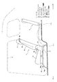
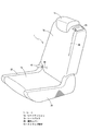
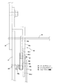
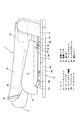
図1は、この発明の実施形態に係る自動車のシート装置を備えた車両を示す側面図であり、図2は、2列目シートを示す斜視図である。なお、図中において、矢印(Fr)は車両前方、矢印(R)は車両後方を示す。図1、図2に示すシート1は、例えば、ミニバンやワゴン車等の3列シートタイプの車両において、運転席や助手席となる前列シート(不図示)後方に設置される2列目シートであり、
フロアパネル2上に設置されている。ここで、図1において、シート1後方のフロアパネル2上に設置されたシート3は、3列目シートである。
Hereinafter, embodiments of the present invention will be described in detail with reference to the drawings.
FIG. 1 is a side view showing a vehicle equipped with an automobile seat device according to an embodiment of the present invention, and FIG. 2 is a perspective view showing a second row seat. In the figure, the arrow (Fr) indicates the front of the vehicle, and the arrow (R) indicates the rear of the vehicle. The
It is installed on the floor panel 2. Here, in FIG. 1, the seat 3 installed on the floor panel 2 behind the
また、図1にて一点鎖線で示す部位4は、車体側部においてシート1近傍の略左右両側に形成された乗降口であり、乗員は、この乗降口4を利用してシート1および3列目シート3へ乗り込んだり、下車したりすることができるようになっている。
Also, site 4 shown by a chain line in FIG. 1 is a door opening formed in a substantially right and left sides of the
また、シート1は、フロアパネル2上に座面を形成するシートクッション1aが、図1に示すシートスライド機構10を介してフロアパネル2に対し車両前後方向にスライド可能とされるとともに、前後スライド位置で位置決め可能に支持されている。
Further, the
シートスライド機構10は、フロアパネル2に設けられたロアレール10aと、該ロアレール10aに対して車両前後方向にスライド可能とされるアッパレール10bとを有している。
The
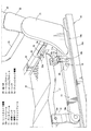
図1、図2に示すシート1は、シートクッション1aと、このシートクッション1aの後端部に枢支されて上方に起立するシートバック1bと、シートバック1bの上部にて乗員の頭部を保持するヘッドレスト1cとを有するとともに、シート1は、図3に示すように、その基部をなすベースフレーム11が、アッパレール10bの上面に固定されている。なお、図3は、図1、図2に示すシートのシートバック支持部周辺一方側を前方かつ外側から見た斜視図である。
The
ベースフレーム11は、上下方向に延びる前側および後側リンク12、13の下部を支軸14a、14bを介して回動可能に支持している。
The
そして、前側リンク12および後側リンク13は、その上端部が、シートクッション1aのクッションパン16を取付けたクッションフレーム17の前部側部、後部側部に支軸15a、15bを介して連結されている。これにより、ベースフレーム11は、リンク12、13を介してシートクッション1aをアッパレール10b上に支持している。
The upper end of the
ここで、前側、後側リンク12、13が図3に示すように起立姿勢となっている時には、シートクッション1aは、適度な高さ位置に座面が位置する正規の上方着座位置に保持される一方、両リンク12、13の上端部が支軸14a、14bを中心とした回動によって前方移動した時には、上記上方着座位置に対して下斜め前方の折り畳み位置に移動するようになっている。
Here, when the front and
また、ベースフレーム11および後側リンク13には、それぞれシート幅方向内側に突出する係止ピン18、19が取付けられており、両係止ピン18、19には、後述する板バネ20の両端が係止されている。
The
板バネ20は、その長手方向中央部が側面視で略円弧状をなして弾性変形可能とされるとともに、両端部は、係止ピン18、19へ係止させるべく側面視で円弧状に折り返されている。後側リンク13には、板バネ20によって、シートクッション1aを上方着座位置に移動させるための付勢力が付与されている。
The
また、ベースフレーム11には、後側リンク13の後部に当接するストッパ部11aが形成されており、このストッパ部11aにより、後側リンク13が板バネ20の付勢力で必要以上に回動することを規制している。
Further, the
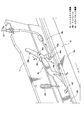
図4は、図1、図2に示すシートのシートバック支持部周辺を前方かつシート幅方向内側から見た斜視図であり、シート幅方向一方側を示している。ベースフレーム11の後部には、図3、図4に示すようなベースブラケット21が取付けられており、シート1では、このベースフレーム11およびベースブラケット21が、図1、図2に示すような、シートクッション1aの左右の側辺部等を覆う保護カバー22により隠蔽されている。
FIG. 4 is a perspective view of the seat back support portion periphery of the seat shown in FIGS. 1 and 2 as viewed from the front and from the inside in the seat width direction, and shows one side in the seat width direction. A
ベースブラケット21は、シートバック1bのシートバックフレーム23に連結ブラケット24を介して取付けられたナックルブラケット25を回動可能に支持している。ナックルブラケット25は、その上部が平板状をなして連結ブラケット24に接合される一方、下部が略円筒状をなして回動中心部25aを構成しており、この回動中心部25aが、ベースブラケット21に回動可能に支持されている。
The
ナックルブラケット25の回動中心部25aには、その中心において、シート幅方向に延びるシャフト26の一端側が貫通配置されている。このシャフト26は、リンク27を介してケーブル28に接続され、図1、図2に示すように、シートバック1b上面のヘッドレスト1c側方に配設された操作レバー29に接続されている。
One end side of the
また、回動中心部25aには、その内面側に円弧状のスリット孔25bが形成されており、このスリット孔25bに沿ってスライド移動可能にスライダピン30が配設されている。そして、このスライダピン30は、上下に延びるケーブル31を介してリンク32の一端側に接続されている。
In addition, an
リンク32は、シート幅方向に延びる板状の部材とされ、その長手方向の略中央部が、シート幅方向に延びるアンカーバー33前面に支軸34を介して枢支されている。
The
さらに、リンク32の長手方向他端側には、下方に突出する押込みヘッド部32aが形成されており、後述するクッションロック機構35を構成するロック爪35aの後部上方に位置している。
Further, a
クッションロック機構35は、図5に示すように、ロック爪35aの他、アンカーバー33に接合されたブラケット35bと、該ブラケット35bに対してロック爪35aを回動可能に枢支する支軸35cと、ロック爪35aに形成された係止端35d側を下方に付勢するバネ部35eとから構成されている。
As shown in FIG. 5, the
ロック爪35aの係止端35dは、クッションフレーム17の後部に取付けられた略ハット状をなす被係止部36の上方に位置してこれと係合可能に構成されており、支軸35cを中心としたロック爪35aの回動により、被係止部36に対する係合、離反を切り替えることが可能になっている。
A locking
ここで、クッションロック機構35では、係止端35dと被係止部36との係合状態がバネ部35eの付勢力によって保持できるようになっている。このため、被係止部36との係合を解除しない限り、ロック爪35aは被係止部36との係合状態を保持して上方着座位置でシートクッション1aの下斜め前方への移動を規制する。
Here, in the
なお、ブラケット35bに凸状に形成された部位35fは、バネ部35eの付勢力によって係止端35dが必要以上に下方へ変位することを防止するためのストッパ部である。
A
図6は、図1、図2に示すシートのシートバック支持部周辺を前方かつシート幅方向内側から見た時の斜視図であり、シート幅方向他方側を示している。シート1には、ベースフレーム11がシート幅方向の両側に配設されており、ベースブラケット21(図4参照)が配設される側を一方側とした場合、それと異なる他方側のベースフレーム11の後部にも、図6に示すように、ベースブラケット21(図4参照)に対応するベースブラケット37が取付けられている。
6 is a perspective view when the periphery of the seat back support portion of the seat shown in FIGS. 1 and 2 is viewed from the front and the inner side in the seat width direction, and shows the other side in the seat width direction. In the
ここで、ベースブラケット21および37には、アンカーバー33の端部が接合され、ベースブラケット21、37同士がアンカーバー33によって橋渡されるような構造となっている。シート1では、このアンカーバー33により剛性の向上が図られている。
Here, the end portions of the
また、ベースブラケット37は、ベースブラケット21と同様、ナックルブラケット25(図4参照)に対応するナックルブラケット38を回動可能に支持している。ナックルブラケット38は、その上端部が連結ブラケット39に接合されており、この連結ブラケット39を介してシートバックフレーム23に連結されている。
Moreover, the
このように、シート1では、シートバック1bのシートバックフレーム23に取付けられたナックルブラケット25、38、および、ベースブラケット21、37により、リクライニング機構を構成しており、ナックルブラケット25、38がベースブラケット21、37により回動可能に支持されることで、シートバック1bは、その下部を中心に回動しながら前傾動作することが可能になっている。
Thus, in the
ところで、図4に示すシャフト26は、その他端側が、図6に示すベースブラケット37およびナックルブラケット38に貫通配置されており、ベースブラケット37の内側に配設されたウォークイン機構40を構成する第1リンク40aの支軸を構成している。
Incidentally, the other end side of the
ウォークイン機構40は、図6、図7に示すように、側面視で略く字状をなす第1リンク40aと、第1リンク40aの下端と当接する第2リンク40bと、側面視で略Y字状をなし、第2リンク40bと支軸40dを介して連結される第3リンク40cと、ナックルブラケット38の内面側に締結されたキックプレート40eとにより構成されている。
As shown in FIGS. 6 and 7, the walk-in
また、ウォークイン機構40には、第2リンク40bと第3リンク40cとを連結する支軸40dに、図1、図2、および図6に示すようなストラップ部材41がケーブル42を介して接続されている。
Moreover, the walk-in
第1リンク40aは、第2リンク40bと当接可能とされることで、該第2リンク40bの変位によりシャフト26を中心に回動可能とされている。また、第2リンク40bは、その一端部が支軸40fに枢支されるとともに、ベースブラケット37に一端が固定されたバネ40gにより、他端部を後方へ移動させるための付勢力が付与されている。また、第3リンク40cは、支軸40dから放射状に3箇所延出部40c1、40c2、40c3が形成されており、そのうち、上方、下方に延びる延出部40c1、40c2は、先端部がそれぞれキックプレート40eの下部、アンカーバー33に近接するように配置され、延出部40c3は、下方に延びるケーブル43を介して、図8に示すスライドロック解除機構44に接続されている。
Since the
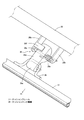
図8は、スライドロック解除機構44を示す斜視図である。スライドロック解除機構44は、ロアレール10aに対するアッパレール10bの車両前後方向の位置決め状態を解除し、シートクッション1aの前後スライドを許容するための機構である。このスライドロック解除機構44は、主に、ケーブル43に連結された第1リンク44aと、該第1リンク44aの前方に配設された第2リンク44bとにより構成される。
FIG. 8 is a perspective view showing the slide
第1リンク44aは、支軸44cを介してベースフレーム11に回動可能に支持されるとともに、その下端部には孔部44dが穿設されており、この孔部44dにケーブル43先端の差込具43aが差し込まれることで、ケーブル43と第1リンク44aとが連結されている。さらに、第1リンク44aは、その前端部において、内側に折曲された押込み突片44eを有しており、この押込み突片44eが第2リンク44b後端部上方を覆う位置に配置されている。
The
第2リンク44bは、支軸44fを介してベースフレーム11に回動可能に支持されるとともに、その後端部と支軸44fとの間には、下方延出部44gが形成されている。この下方延出部44gの下端部には、前後方向に一定間隔で下方に延びる突起を有する櫛歯部(不図示)が形成されており、この櫛歯部は、公知のように、ロアレール10aの上面部において上記櫛歯部の突起の前後間隔と等間隔で形成された孔部(不図示)と係合可能とされている。
The
ここで、第2リンク44bは、支軸44fに枢支されていることで、後部側が上下動可能とされている。シートスライド機構10では、第2リンク44bの後部側が上方に位置した時、第2リンク44b側の上記櫛歯部の突起とロアレール10a側の孔部とが係合する。そして、シートクッション1aの前後方向のスライド移動が規制されて位置決めがなされる。一方、上記後端部が下方に位置した時には、上記櫛歯部の突起と孔部との係合が解除された状態となり、シートクッション1aが、前後方向に移動可能となる。
Here, the
また、支軸44fと下方延出部44g(櫛歯部)との間の部分は、一端部がベースフレーム11に固定されたバネ44hと連結されており、このバネ44hにより、第2リンク44bの支軸44fよりも後側の部分は常時上方に付勢され、通常時にはシートクッション1aの位置決め状態が保持されている。
A portion between the
(シートバック折り畳み操作時)
ここで、図9〜図12をさらに参照して、シートバック1bをシートクッション1a上に折り畳む時の動作について説明する。本実施形態では、上述したように、シートバック1bのシートバックフレーム23に取付けられたナックルブラケット25、38がベースブラケット21、37に対して回動可能に支持されることで、背面が略水平状態もしくは略水平状態に近い緩傾斜状態となる折り畳み位置までシートバック1bを前傾させることができるようになっている。
(When folding the seat back)
Here, with reference to FIG. 9 to FIG. 12, the operation when the seat back 1b is folded on the
この場合、先ず乗員は、図9に示す矢印Aの方向に操作レバー29を引っ張ることにより、ケーブル28を引っ張り、図4に示すように、リンク27を介してシャフト26を矢印Bで示す方向に回転させる。
In this case, the occupant first pulls the
なお、このように、操作レバー29の作動によってシャフト26が回転した時には、ウォークイン機構40(図6参照)では、第1リンク40aが第2リンク40bから離間する方向に回動するため、リンク40b、40cが動作することはない。
As described above, when the
ところで、ベースブラケット21とナックルブラケット25の回動中心部25aとの間には、公知のリクライニングロック解除機構(不図示)が内蔵されている。本実施形態では、上述したようにシャフト26が回転すると、上記解除機構を構成するカムが回動し、シートバック1bの起立姿勢保持状態が解除されるようになっている。
Incidentally, a known reclining lock releasing mechanism (not shown) is built in between the
このように、シートバック1bの起立姿勢保持状態が解除されると、ナックルブラケット25、38が回動可能な状態となり、シートバック1bは、図9に示すように、不図示の付勢手段の付勢力によって前傾する方向に回動する。
In this way, when the standing posture holding state of the seat back 1b is released, the
この時、ナックルブラケット25が図4および図10に示す矢印Cの方向に回動することとなるが、ナックルブラケット25が図10で示す所定角度θ1だけ回動すると、スリット孔25bの一端部とスライダピン30とが当接するようになっており、これに伴ってケーブル31が図10にて矢印Dで示すように上方に引っ張られるようになっている。
At this time, the
これにより、リンク32は、図11(a)にて矢印Eで示すように反時計方向に回動し、クッションロック機構35のロック爪35aの後部を、バネ35eの付勢力に抗して矢印Fで示すように下方に移動させる。この時、ロック爪35aは、支軸35cを中心に図11(b)にて矢印Gで示すように時計方向に回動して、係止端35dと被係止部36との係合を解除し、シートクッション1aの上方着座位置での移動規制状態を解除する。
As a result, the
本実施形態では、シートバック1bの前傾動作時、その前面下部がシートクッション1aの後部に当接するようになっており、上述したように上方着座位置での移動規制状態が解除された時には、シートバック1bの前傾動作時の押圧力によってシートクッション1aを折り畳み位置に移動させることが可能になっている。
In the present embodiment, when the seat back 1b is tilted forward, the lower part of the front surface comes into contact with the rear portion of the
この時、板バネ20は、弾性変形を伴いながら、図12(a)に示す状態から同図(b)で示す状態に変化し、その結果、シートクッション1aは前後のリンク12、13の回動により下斜め前方の折り畳み位置に移動(ダイブダウン)する。
At this time, the
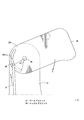
このため、シートバック1bをシートクッション1a上に折り畳んだ時には、シートクッション1aのダイブダウンによって、図13に示すようにシートバック1bの背面を略水平状態にすることができ、上記背面の荷物を安定的に載置することが可能になる。
For this reason, when the seat back 1b is folded onto the
このように、本実施形態では、シートクッション1aとシートバック1bとをリンク機構等を介して連結しなくとも、操作レバー29の作動に伴いシートバック1bが前傾動作し、リンク32がクッションロック機構35の上記規制状態を解除した時には、シートクッション1aをシートバック1bで押圧しながら折り畳み位置に移動させることを可能にしている。
As described above, in the present embodiment, the seat back 1b moves forward in accordance with the operation of the
この場合、シートクッション1aとシートバック1bとを連結しない構成とすることで、車両走行時のシートバック1bの振動がシートクッション1a側に伝達されることを抑制でき、乗員着座時の不快感を解消することができる。
In this case, by not connecting the
特に、ミニバンやワゴン車等の車種においてシートクッション1aがシートスライド機構10により移動可能に構成されている場合には、シートクッション1aがシートスライド機構10によってフロアパネル2から上方に離間して配置されているため、シートバック1bの振動がシートクッション1aに伝達され易い構造となっている。
In particular, when the
また、車両の駆動方式をフロントエンジン・フロントドライブの所謂FFタイプとした場合には、車両前部に重心が位置するために、後列側のシート1がより振動し易くなることが分かっている。
Further, when the vehicle driving system is a so-called FF type of a front engine / front drive, it has been found that the rear
従って、本実施形態のように、シートクッション1aとシートバック1bとをリンク機構等を介して連結しない構成は、上述したようにシートクッション1aがシートスライド機構10によって移動可能に構成されているものや、車両の駆動方式がFFタイプとされているものにおいて、より好適となる。
Therefore, the configuration in which the
さらに、本実施形態では、リンク32がクッションロック機構35によるシートクッション1aの移動規制状態を解除した後、前傾動作時のシートバック1bの押圧力を利用することで、シートクッション1aを折り畳み位置に確実に移動させることができる。
Furthermore, in this embodiment, after the
また、ベースフレーム11が、シートクッション1aを前側、後側のリンク12、13を介してシートスライド機構10のアッパレール10b上に支持していることにより、シートクッション1aを前後で安定的に支持することができ、これを下斜め前方の折り畳み位置に確実に移動させることができる。
The
また、シートバック1bを所定角度θ1だけ前傾させた時、この前傾に連動してリンク32がシートロック機構35によるシートクッション1aの移動規制状態を解除するようにしたため、操作レバー29の作動でシートバック1bが前傾動作した時には、シートクッション1aを確実に折り畳み位置に移動させることができる。
Further, when the seat back 1b is tilted forward by a predetermined angle θ1, the
ところで、図13に示す状態から、シートバック1bを起立姿勢の状態に復帰させると、板バネ20の付勢力の作用でクッション1aが上方着座位置に向かって後方かつ上方に押動されるようになっている。そして、バネ35eの付勢力によって初期位置に戻されたロック爪35aの係止端35dに、クッションフレーム17に取付けられた被係止部36を当接させることができるようになっている。
By the way, when the seat back 1b is returned to the standing posture from the state shown in FIG. 13, the
この時、ロック爪35aには被係止部36の押圧力が作用し、ロック爪35aは、バネ35eの付勢力に抗して矢印G(図11(b)参照)の方向に回動する。そして、ロック爪35aの係止端35dが、被係止部36の押圧力によって上方に押し上げられ、被係止部36がさらに後方に進出して係止端35dを乗り越えた時、ロック爪35aがバネ35eの付勢力の作用により矢印Gと逆方向に回動し、両者は再び係合することになる。このように、ロック爪35aと被係止部36とが再度係合することで、シートバック1bの上記復帰操作のみによってシートクッション1aは、上方着座位置に保持される状態に復帰することができる。
At this time, the pressing force of the locked
本実施形態では、板バネ20を備えて、折り畳み位置にあるシートクッション1aを上方着座位置に復帰させるようにしたため、板バネ20の付勢力を利用する簡素な構成でありながら、シートクッション1aの復帰動作のための操作性を向上させることができる。
In the present embodiment, since the
(3列目シート乗降操作時)
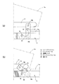
次に、図14〜図16をさらに参照して、3列目シート3(図2、図16参照)の乗員を乗降させるべく所定の操作を行った時の動作について説明する。本実施形態では、上述したように、シートクッション1aが、シートスライド機構10によってスライド可能に支持されつつ、シートバック1bのシートバックフレーム23が、ベースブラケット21、37に対して回動可能に支持されることで、シートバック1bを若干前傾させた退避状態としつつ、シート1を前方にスライド移動させた時、3列目シート3の乗員は、乗降口4から乗降できるようになっている。
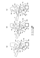
(During the third row seat entry / exit operation)
Next, with reference to FIGS. 14 to 16, the operation when a predetermined operation is performed to get on and off the passenger in the third row seat 3 (see FIGS. 2 and 16) will be described. In this embodiment, as described above, the
この場合、先ず乗員は、図14(a)に示す初期状態において、同図(b)にて矢印Hで示す方向にストラップ部材41を引っ張る。この時、第2、第3リンク40b、40cはバネ40gの付勢力に抗して支軸40fを中心に矢印Iで示す反時計方向に回動する。
In this case, first, the occupant pulls the
また、この時、第2リンク40bの上記回動に伴い、これに当接する第1リンク40aは矢印Jで示すように時計方向に回動し、これによってシャフト26が矢印Bの方向に回転する。
At this time, as the
このようにシャフト26が回転すると、上述したシートバック1bの折り畳みの場合と同様、上記リクライニングロック解除機構においてシートバック1bの起立姿勢保持状態が解除され、シートバック1bが前傾方向に回動させられる。
When the
そして、シートバック1bが前傾し始めると、ナックルブラケット38(図6参照)の回動に伴ってこれに締結固定されたキックプレート40eが、図14(c)に示すように、矢印Kで示す反時計方向に回動する。
When the seat back 1b starts to tilt forward, the
このようにキックプレート40eが回動すると、ストラップ部材41が操作された時点で既に第3リンク40cが前方に移動していることにより、キックプレート40eの下部と第3リンク40の延出部40c1とが当接し、キックプレート40eのさらなる回動によって第3リンク40cが矢印Lで示す時計方向に回動するようになっている。
When the
この時、第3リンク40cの上記回動に伴って、延出部40c3が上方に変位することになるが、この延出部40c3の変位により、これに接続されたケーブル43が矢印Mで示すように上方に引っ張られることになる。
At this time, along with the rotation of the
そして、このようにケーブル43が引っ張られると、図8に示すスライドロック機構44の第1リンク44aが、支軸44cを中心にして矢印Nで示す方向に回動し、押込み突片44eを下方に変位させる。この時、第2リンク44bの後端部が下方に押圧され、バネ44hの付勢力に抗して矢印Pで示す方向に回動する。
When the
そして、この第2リンク44bの回動により、下方延出部44gは矢印Qで示すように下方に移動して、その下端部に形成された櫛歯部の突起とロアレール10a側の孔部との係合が解除される。これにより、アッパレール10bより上方のシートクッション1aの位置決め状態は解除され、シート1は前方にスライド可能な状態となる。
Then, by the rotation of the
ところで、第3リンク40cが図14(c)に示すように回動してスライドロック機構44を作動させた後、さらに回動が進むと、延出部40c2が下方のアンカーバー33に当接し、それ以上の回動が規制されるようになっている。
By the way, after the
従って、キックプレート40eの回動が規制され、ひいてはシートバック1bのさらなる回動が規制される。このような一連の動作により、図15、図16に示すように、シートバック1b(ナックルブラケット25)を若干前方に傾動させた退避状態としつつ、シート1を前方にスライドさせることができ、これによって、3列目シート3では、乗降口4からスムーズに乗降することができる。
Therefore, the rotation of the
本実施形態では、ストラップ部材41を操作した時、上述したようにシートバック1bの回動が途中で規制されるように構成したことで、図15に示すように、ナックルブラケット25のスリット孔25bの一端部とスライダピン30とが当接する角度θ1より小さい角度θ2で,ナックルブラケット25の回動を停止させることができるようになっている。
In the present embodiment, as described above, when the
これにより、ストラップ部材41の操作時には、リンク32は作動せず、シートクッション1aは、クッションロック機構35によって上方着座位置に維持されたままの状態となる。
Accordingly, when the
このように、本実施形態では、シートクッション1aとシートバック1bとがリンク機構等を介して連結されず、かつストラップ部材41が作動した時には、シートバック1bの前傾動作に関わらずシートクッション1aが上方着座位置に維持されるような構成となっている。この場合、シートクッション1aがダイブダウンによって前方に移動することがない分、前列シートとの距離を大きく確保できるため、シート1を前方へ大きくスライドさせることができ、その結果、乗降口4から3列目シート3の乗員が乗降する際の乗降性を向上させることができる。
Thus, in the present embodiment, when the
また、ストラップ部材41の作動でシートバック1bを前傾させた時、シートスライド機構10では、ウォークイン機構40によってスライドロック機構44の位置決め状態を解除できるようにしているため、シートバック1bの前傾時には、シートクッション1aを確実にスライド可能な状態とすることができる。
Further, when the seat back 1b is tilted forward by the operation of the
また、本実施形態では、ストラップ部材41が作動した時、ウォークイン機構40は、シートバック1b前傾時の角度が上記所定角度θ1より小さい第2角度θ2となったところでスライドロック機構44によるスライド位置決め状態を解除するように構成されている。これにより、シートクッション1aの前方へのスライドが可能になる前にシートクッション1aがダイブダウンするといった不具合を確実に防止できる。
In this embodiment, when the
なお、上述した実施形態では、3列目シート3の乗員がシート1側方の乗降口4から乗降できるように、2列目シート1をスライド可能にした場合について説明したが、本発明は必ずしもこれに限定されるものではない。例えば、2列目シートの乗員が1列目(前列)シート側方の乗降口から乗降できるように、前列シートをスライド可能にしたものに本発明を適用してもよい。
In the above-described embodiment, the case where the
この場合、前列シートのスライド時に、そのシートクッションが下斜め前方にダイブダウンすることを規制できるため、前列シートと、その前方に位置するインストルメントパネルとの距離を大きく確保でき、上記前列シートを前方へ大きくスライドさせることが可能になる。その結果、乗降口から2列目シートの乗員が乗降する際の乗降性を向上させることができる。 In this case, when the front row seat is slid, the seat cushion can be restricted from dive-down obliquely forward, so that a large distance between the front row seat and the instrument panel located in front of the front row seat can be secured. It is possible to slide forward greatly. As a result, it is possible to improve the boarding / exiting performance when the passengers in the second row seats get on / off from the entrance / exit.
この発明の構成と、上述の実施形態との対応において、
この発明のシートスライド手段は、シートスライド機構10、ウォークイン機構40、およびスライドロック機構44に対応し、
以下同様に、
支持手段は、ベースフレーム11に対応し、
リクライニング手段は、ベースブラケット21、37、及びナックルブラケット25、38に対応し、
シートロック手段は、クッションロック機構35に対応し、
シートロック解除手段は、リンク32に対応し、
スライドロック解除手段は、ウォークイン機構40に対応し、
操作手段は、操作レバー29およびストラップ部材41に対応するも、
この発明は、上述の実施形態の構成のみに限定されるものではなく、多くの実施の形態を得ることができる。
In correspondence between the configuration of the present invention and the above-described embodiment,
The seat slide means of the present invention corresponds to the
Similarly,
The support means corresponds to the
The reclining means corresponds to the
The seat lock means corresponds to the
The seat lock releasing means corresponds to the
The slide unlocking means corresponds to the walk-in
The operation means corresponds to the
The present invention is not limited only to the configuration of the above-described embodiment, and many embodiments can be obtained.
1…シート
1a…シートクッション
1b…シートバック
2…フロアパネル(フロア)
10…シートスライド機構
10b…アッパレール
11…ベースフレーム(支持手段)
12…前側リンク
13…後側リンク
17…クッションフレーム
20…板バネ
21、37…ベースブラケット
25、38…ナックルブラケット
29…操作レバー(操作手段)
32…リンク(シートロック解除手段)
35…クッションロック機構(シートロック手段)
40…ウォークイン機構(スライドロック解除手段)
41…ストラップ部材(操作手段)
44…スライドロック機構
DESCRIPTION OF
DESCRIPTION OF
DESCRIPTION OF
32 ... Link (seat lock release means)
35. Cushion lock mechanism (seat lock means)
40. Walk-in mechanism (slide lock release means)
41. Strap member (operating means)
44. Slide lock mechanism
Claims (6)
該シートバックを前傾させた折り畳み時に、上記シートクッションを正規の上方着座位置から下斜め前方に移動させて折り畳み位置に移動可能である自動車のシート装置であって、
上記シートクッションを、車体のフロアに対して前後スライド可能とするとともに、前後スライド位置での位置決めを可能とするシートスライド手段と、
上記シートクッションを正規の上方着座位置と下斜め前方に移動させた折り畳み位置とに移動可能に支持する支持手段と、
操作手段の作動により上記シートバックを前傾させるリクライニング手段と、
上方着座位置で上記シートクッションの動きを規制するシートロック手段と、
上記シートロック手段の規制を解除するシートロック解除手段とを備え、
上記シートスライド手段は、上記操作手段の作動により上記リクライニング手段を作動させて上記シートバックを前傾させた時、上記シートスライド手段によるスライド位置決めを解除するとともに、
上記支持手段は、上記シートクッションの上方着座位置を維持し、
上記シートロック解除手段は、上記シートバックの所定角度の前傾時に、この前傾に連動して上記シートロック手段の規制を解除し、
上記シートロック解除手段により上記シートロック手段の規制が解除されたときは、
上記シートクッションは上記折り畳み位置への移動が可能となるように構成された
自動車のシート装置。 The car floor has a seat cushion and a seat back,
When the seat back is tilted forward, the seat cushion can be moved to a folding position by moving the seat cushion downward and obliquely forward from a normal upper seating position,
A seat slide means that enables the seat cushion to slide back and forth with respect to the floor of the vehicle body, and enables positioning at the front and rear slide position;
A support means for movably supporting the seat cushion between a normal upper seating position and a folding position where the seat cushion is moved obliquely forward and downward;
Reclining means for tilting the seat back forward by operation of the operating means ;
Seat locking means for restricting movement of the seat cushion at the upper sitting position;
A seat lock release means for releasing the restriction of the seat lock means,
The seat slide means releases the slide positioning by the seat slide means when the reclining means is actuated by operating the operation means to tilt the seat back forward,
The support means maintains an upper seating position of the seat cushion ;
The seat lock release means releases the restriction of the seat lock means in conjunction with the forward tilt when the seat back is tilted forward by a predetermined angle,
When the restriction of the seat lock means is released by the seat lock release means,
The vehicle seat device configured such that the seat cushion is movable to the folding position .
上記シートロック解除手段は、上記シートバックの前傾状態で上記シートロック手段の規制解除を行うことで、上記シートクッションを上記シートバックで押圧しながら折り畳み位置に移動可能に構成した
請求項1記載の自動車のシート装置。 The reclining means enables the seat back to be tilted forward to a folding position where the back of the seat back is in a substantially horizontal state or a gently inclined state close to a substantially horizontal state,
The seat lock releasing means is configured to be able to move to a folding position while pressing the seat cushion with the seat back by releasing the restriction of the seat lock means in a forward tilt state of the seat back. Car seat equipment.
請求項1または2記載の自動車のシート装置。 The vehicle seat device according to claim 1 or 2, wherein the support means supports the front side and the rear side of the frame member of the seat cushion on the upper rail of the seat slide means via a front side link and a rear side link. .
請求項3記載の自動車のシート装置。 The automobile seat device according to claim 3, further comprising a spring for applying a predetermined urging force for returning the seat cushion from the folded position to the upper seating position.
請求項1または2記載の自動車のシート装置。 The seat slide means includes a slide lock release means for releasing the slide positioning by the seat slide means when the reclining means is actuated by operating the operation means to tilt the seat back forward. Car seat equipment.
請求項1記載の自動車のシート装置。 The slide lock releasing means, the sheet equipment automobile <br/> claim 1, wherein to release the slide positioned in front傾時the predetermined angle smaller than the first angle of the seat back.
Priority Applications (1)
| Application Number | Priority Date | Filing Date | Title |
|---|---|---|---|
| JP2008197720A JP5347364B2 (en) | 2008-07-31 | 2008-07-31 | Car seat equipment |
Applications Claiming Priority (1)
| Application Number | Priority Date | Filing Date | Title |
|---|---|---|---|
| JP2008197720A JP5347364B2 (en) | 2008-07-31 | 2008-07-31 | Car seat equipment |
Publications (3)
| Publication Number | Publication Date |
|---|---|
| JP2010030559A JP2010030559A (en) | 2010-02-12 |
| JP2010030559A5 JP2010030559A5 (en) | 2012-07-26 |
| JP5347364B2 true JP5347364B2 (en) | 2013-11-20 |
Family
ID=41735579
Family Applications (1)
| Application Number | Title | Priority Date | Filing Date |
|---|---|---|---|
| JP2008197720A Expired - Fee Related JP5347364B2 (en) | 2008-07-31 | 2008-07-31 | Car seat equipment |
Country Status (1)
| Country | Link |
|---|---|
| JP (1) | JP5347364B2 (en) |
Families Citing this family (1)
| Publication number | Priority date | Publication date | Assignee | Title |
|---|---|---|---|---|
| JP5174875B2 (en) | 2010-09-17 | 2013-04-03 | 日立建機株式会社 | Hybrid wheel loader |
Family Cites Families (5)
| Publication number | Priority date | Publication date | Assignee | Title |
|---|---|---|---|---|
| JPH0173429U (en) * | 1987-11-05 | 1989-05-17 | ||
| JP4582474B2 (en) * | 2003-09-03 | 2010-11-17 | テイ・エス テック株式会社 | Folding seat for automobile |
| EP1790522B1 (en) * | 2004-09-17 | 2013-07-31 | Aisin Seiki Kabushiki Kaisha | Walk-in device |
| JP2007223499A (en) * | 2006-02-24 | 2007-09-06 | Mazda Motor Corp | Vehicle seat structure |
| JP2009089871A (en) * | 2007-10-09 | 2009-04-30 | Hino Motors Ltd | Seat device for vehicle |
-
2008
- 2008-07-31 JP JP2008197720A patent/JP5347364B2/en not_active Expired - Fee Related
Also Published As
| Publication number | Publication date |
|---|---|
| JP2010030559A (en) | 2010-02-12 |
Similar Documents
| Publication | Publication Date | Title |
|---|---|---|
| JP4176118B2 (en) | Vehicle seat device | |
| EP2261078B1 (en) | Erroneous operation preventing device and stowable seat for vehicle | |
| JP6882140B2 (en) | Seat slide mechanism | |
| JP2008087691A (en) | Vehicle seat device | |
| EP2269864A1 (en) | Stowable vehicle seat | |
| WO2017110438A1 (en) | Automobile seat | |
| JP5845949B2 (en) | Vehicle seat slide device | |
| JP4918980B2 (en) | Vehicle seat device | |
| JP2005041274A (en) | Seat device | |
| JP4712036B2 (en) | Car seat | |
| JP2009029272A (en) | Walk-in seat slide device | |
| JP5910816B2 (en) | Sheet device | |
| JP5347364B2 (en) | Car seat equipment | |
| KR20060010948A (en) | Walk-in device for second seat of vehicle | |
| JP6562005B2 (en) | Entry / exit support structure for vehicle seats | |
| JP2010030559A5 (en) | ||
| JP5690369B2 (en) | Sheet device | |
| KR102706253B1 (en) | Walkin apparatus of seat for vehicle | |
| JP7310634B2 (en) | Vehicle slide rail device | |
| WO2017208573A1 (en) | Vehicular seat slide device | |
| JP7381854B2 (en) | vehicle seat | |
| JP2009035197A (en) | Vehicular seat | |
| JP2009073312A (en) | Operation structure of vehicular seat | |
| JP2005029104A (en) | Vehicular seat device | |
| JP3517125B2 (en) | Variable position and attitude device for automotive seats |
Legal Events
| Date | Code | Title | Description |
|---|---|---|---|
| A621 | Written request for application examination |
Free format text: JAPANESE INTERMEDIATE CODE: A621 Effective date: 20110523 |
|
| A521 | Written amendment |
Free format text: JAPANESE INTERMEDIATE CODE: A523 Effective date: 20120522 |
|
| A521 | Written amendment |
Free format text: JAPANESE INTERMEDIATE CODE: A523 Effective date: 20120607 |
|
| A977 | Report on retrieval |
Free format text: JAPANESE INTERMEDIATE CODE: A971007 Effective date: 20130208 |
|
| A131 | Notification of reasons for refusal |
Free format text: JAPANESE INTERMEDIATE CODE: A131 Effective date: 20130219 |
|
| A521 | Written amendment |
Free format text: JAPANESE INTERMEDIATE CODE: A523 Effective date: 20130403 |
|
| A131 | Notification of reasons for refusal |
Free format text: JAPANESE INTERMEDIATE CODE: A131 Effective date: 20130430 |
|
| A521 | Written amendment |
Free format text: JAPANESE INTERMEDIATE CODE: A523 Effective date: 20130625 |
|
| TRDD | Decision of grant or rejection written | ||
| A01 | Written decision to grant a patent or to grant a registration (utility model) |
Free format text: JAPANESE INTERMEDIATE CODE: A01 Effective date: 20130723 |
|
| A61 | First payment of annual fees (during grant procedure) |
Free format text: JAPANESE INTERMEDIATE CODE: A61 Effective date: 20130805 |
|
| R150 | Certificate of patent or registration of utility model |
Ref document number: 5347364 Country of ref document: JP Free format text: JAPANESE INTERMEDIATE CODE: R150 Free format text: JAPANESE INTERMEDIATE CODE: R150 |
|
| LAPS | Cancellation because of no payment of annual fees |