JP5342386B2 - Method for removing fluorine compound deposited on source housing of ion generator and ion generator - Google Patents
Method for removing fluorine compound deposited on source housing of ion generator and ion generator Download PDFInfo
- Publication number
- JP5342386B2 JP5342386B2 JP2009216241A JP2009216241A JP5342386B2 JP 5342386 B2 JP5342386 B2 JP 5342386B2 JP 2009216241 A JP2009216241 A JP 2009216241A JP 2009216241 A JP2009216241 A JP 2009216241A JP 5342386 B2 JP5342386 B2 JP 5342386B2
- Authority
- JP
- Japan
- Prior art keywords
- chamber
- filament
- gas
- power source
- fluorine
- Prior art date
- Legal status (The legal status is an assumption and is not a legal conclusion. Google has not performed a legal analysis and makes no representation as to the accuracy of the status listed.)
- Expired - Fee Related
Links
Images


Classifications
-
- H—ELECTRICITY
- H01—ELECTRIC ELEMENTS
- H01J—ELECTRIC DISCHARGE TUBES OR DISCHARGE LAMPS
- H01J37/00—Discharge tubes with provision for introducing objects or material to be exposed to the discharge, e.g. for the purpose of examination or processing thereof
- H01J37/30—Electron-beam or ion-beam tubes for localised treatment of objects
- H01J37/317—Electron-beam or ion-beam tubes for localised treatment of objects for changing properties of the objects or for applying thin layers thereon, e.g. for ion implantation
- H01J37/3171—Electron-beam or ion-beam tubes for localised treatment of objects for changing properties of the objects or for applying thin layers thereon, e.g. for ion implantation for ion implantation
-
- H—ELECTRICITY
- H01—ELECTRIC ELEMENTS
- H01J—ELECTRIC DISCHARGE TUBES OR DISCHARGE LAMPS
- H01J37/00—Discharge tubes with provision for introducing objects or material to be exposed to the discharge, e.g. for the purpose of examination or processing thereof
- H01J37/02—Details
- H01J37/04—Arrangements of electrodes and associated parts for generating or controlling the discharge, e.g. electron-optical arrangement, ion-optical arrangement
- H01J37/08—Ion sources; Ion guns
-
- H—ELECTRICITY
- H01—ELECTRIC ELEMENTS
- H01J—ELECTRIC DISCHARGE TUBES OR DISCHARGE LAMPS
- H01J2237/00—Discharge tubes exposing object to beam, e.g. for analysis treatment, etching, imaging
- H01J2237/02—Details
- H01J2237/022—Avoiding or removing foreign or contaminating particles, debris or deposits on sample or tube
Abstract
Description
本発明は、イオン注入装置を構成するイオン発生装置に関する。 The present invention relates to an ion generator that constitutes an ion implantation apparatus.
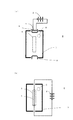
図3は、従来のイオン発生装置の形態を示す概念図である。図3(a)に示すように、イオン発生装置9は、チャンバー7と、チャンバー内に熱電子を発生するためのカソード8と、チャンバー7の外側であってカソード8の近傍に配置されたフィラメント1と、フィラメント1に直列接続されている直流電源2と、チャンバー7にガスを導入するガス導入口5と、チャンバー7内で発生したイオンを外部へ引き出すイオンビーム取り出し口6などから構成されている。図3(b)ではフィラメント1がチャンバー7の内側に配置される構成となっている。
FIG. 3 is a conceptual diagram showing a form of a conventional ion generator. As shown in FIG. 3A, the
イオン注入装置において、BF3などのフッ素化合物ガスをイオンソースガスとしてイオン注入作業を行うと、上記イオン発生装置やソースハウジング等にフッ素化合物ガスから生成されるフッ素を含有する析出物が堆積してしまう。イオン発生装置やソースハウジングをクリーニングするためには、大気開放をする必要があるが、フッ素を含有する析出物と大気中の水分が反応しHFが生成されるため、HFを含む蒸気がクリーンルーム内に拡散してしまうという懸念がある。 In an ion implantation apparatus, when an ion implantation operation is performed using a fluorine compound gas such as BF3 as an ion source gas, a precipitate containing fluorine generated from the fluorine compound gas is deposited on the ion generation apparatus or the source housing. . In order to clean the ion generator and the source housing, it is necessary to open the atmosphere. However, since the precipitate containing fluorine reacts with moisture in the atmosphere to generate HF, the vapor containing HF is in the clean room. There is concern that it will spread.
クリーンルーム内へのHF蒸気の拡散を防止するために、ソースハウジング内を大気パージし、その後、真空ポンプで真空引きを行い、また、大気パージをする工程を繰り返して、フッ素を含有する析出物の量を減らす、あるいは、HF蒸気を含む大気が排出される経路に、除害装置を有する排気経路と吸引排気ポンプを設ける、などの方策を施している。(例えば、特許文献1参照)
一方、BF3などのフッ素化合物ガスのイオン注入作業の後に、PH3などの水素化合物ガスを用いてイオン注入作業を行うと、水素化合物ガスをイオン化することにより発生する水素イオンとフッ素を含有する析出物との還元反応により、HF蒸気となり、真空ポンプで排気されるので、フッ素を含有する析出物が減ることが、経験的にわかっている。従って、大気開放前には、水素化合物ガスをイオン化して水素イオンを発生させソースハウジング内に導入した後に、水素化合物ガスの導入を止めて、Arガスなどの不活性ガスに切り替えて導入することにより、水素化合物ガスの濃度を薄めた後に、大気パージする方法も有効である。
In order to prevent diffusion of HF vapor into the clean room, the inside of the source housing is purged to the atmosphere, and then the vacuum pump is evacuated and the process of purging to the atmosphere is repeated to remove the fluorine-containing precipitate. Measures are taken such as reducing the amount or providing an exhaust passage having a detoxifying device and a suction exhaust pump in a route through which the atmosphere containing HF vapor is discharged. (For example, see Patent Document 1)
On the other hand, when an ion implantation operation is performed using a hydrogen compound gas such as PH 3 after an ion implantation operation of a fluorine compound gas such as BF 3 , hydrogen ions and fluorine generated by ionizing the hydrogen compound gas are contained. It has been empirically known that, due to the reduction reaction with the precipitate, HF vapor is generated and exhausted by the vacuum pump, so that the precipitate containing fluorine is reduced. Therefore, before opening to the atmosphere, after hydrogen compound gas is ionized to generate hydrogen ions and introduced into the source housing, the introduction of hydrogen compound gas is stopped and switched to an inert gas such as Ar gas. Thus, a method of purging the atmosphere after reducing the concentration of the hydrogen compound gas is also effective.
BF3などのフッ素化合物ガスおよび、AsH3、PH3などの水素化合物ガスをイオンソースとして導入するイオン注入装置において、大気開放前に、水素化合物ガスをイオン化してソースハウジング等に堆積しているフッ素を含有する析出物と反応させて析出物を除去することが有効である。ところで、大気開放をする場合の一つとして、カソードフィラメントが切れてしまった場合に、カソードフィラメントを交換するために、ソースハウジングを大気開放する場合がある。カソードフィラメントが切れる場合として、水素化合物ガスを用いてイオン注入中にカソードフィラメントが切れてしまう場合と、フッ素化合物ガスを用いてイオン注入中にカソードフィラメントが切れてしまう場合とがある。水素化合物ガスを用いてイオン注入中にカソードフィラメントが切れてしまった場合には、水素化合物ガスの導入を止め、不活性ガスや大気と置換して大気開放を行うが、フッ素化合物ガスを用いてイオン注入中にカソードフィラメントが切れてしまった場合には、フッ素化合物ガスから水素化合物ガスに切り替えて、水素化合物ガスをイオン化することができない。そこで、本発明は、カソードフィラメントが切れた後に、カソードフィラメントが切れた状態で水素化合物ガスをイオン化し、ソースハウジング等に堆積したフッ素化合物を除去する方法を提供するものである。 In an ion implantation apparatus that introduces a fluorine compound gas such as BF 3 and a hydrogen compound gas such as AsH 3 or PH 3 as an ion source, the hydrogen compound gas is ionized and deposited on the source housing or the like before being opened to the atmosphere. It is effective to remove the precipitate by reacting with a precipitate containing fluorine. By the way, as one of the cases where the atmosphere is opened to the atmosphere, there is a case where the source housing is opened to the atmosphere in order to replace the cathode filament when the cathode filament is cut. As a case where the cathode filament is broken, there are a case where the cathode filament is broken during ion implantation using the hydrogen compound gas and a case where the cathode filament is broken during ion implantation using the fluorine compound gas. If the cathode filament breaks during ion implantation using hydride gas, the introduction of hydride gas is stopped and the atmosphere is released by replacing it with inert gas or the atmosphere. If the cathode filament breaks during ion implantation, the hydrogen compound gas cannot be ionized by switching from the fluorine compound gas to the hydride gas. Therefore, the present invention provides a method for removing a fluorine compound deposited on a source housing or the like by ionizing a hydrogen compound gas in a state where the cathode filament is cut after the cathode filament is cut.
上記課題を解決するために、以下のような手段をとった。 In order to solve the above problems, the following measures were taken.
まず、チャンバーと、チャンバー内に熱電子を発生するためのカソードと、チャンバーの外側に配置されカソードの近傍に配置されたフィラメントと、フィラメントに直列接続されている直流電源と、チャンバー内にガスを導入するガス導入口と、チャンバー内で発生したイオンを外部へ引き出すイオンビーム取り出し口と、チャンバー内に向い合わせに配置された1対の対向電極と、チャンバー外にあって前記対向電極に接続されている高周波電源とにより構成されていることを特徴とするイオン発生装置とする。 First, a chamber, a cathode for generating thermoelectrons in the chamber, a filament disposed outside the chamber and in the vicinity of the cathode, a direct current power source connected in series to the filament, and a gas in the chamber A gas introduction port to be introduced, an ion beam extraction port through which ions generated in the chamber are extracted to the outside, a pair of counter electrodes disposed facing each other in the chamber, and connected to the counter electrode outside the chamber The ion generator is characterized by comprising a high-frequency power source.
また、チャンバーと、チャンバーの中に配置され熱電子を発生するためのフィラメントと、フィラメントに直列接続されている直流電源と、チャンバー内にガスを導入するガス導入口と、チャンバー内で発生したイオンを外部へ引き出すイオンビーム取り出し口と、フィラメントの両端であって、直流電源と前記フィラメントとの間に1枚ずつ配置された対向電極と、直流電源と並列して配置される高周波電源とにより構成され、直流電源と高周波電源はスイッチにより対向電極との接続を選択できるようになっていることを特徴とするイオン発生装置とする。 Also, a chamber, a filament disposed in the chamber for generating thermoelectrons, a direct current power source connected in series to the filament, a gas inlet for introducing gas into the chamber, and ions generated in the chamber An ion beam extraction port for drawing out the outside, opposite ends of the filament, each disposed between the DC power source and the filament, and a high frequency power source arranged in parallel with the DC power source The ion generator is characterized in that the direct current power source and the high frequency power source can be connected to the counter electrode by a switch.
本発明によれば、カソードフィラメントが切れた場合でも、水素化合物ガスをイオン化するために設けた対向電極に高周波電源を印加することで水素化合物ガスをイオン化し、水素イオンを発生させることにより、真空中でソースハウジング内に堆積したフッ素化合物を還元し、その反応で発生したフッ素を含むガスを真空ポンプで排気し、安全に除害装置施設に排出できる。また、大気開放時に発生するHFガスも低減されるので、大気中に放出されるHFガスも低減される。 According to the present invention, even when the cathode filament breaks, a vacuum is generated by ionizing the hydride gas by applying a high-frequency power source to the counter electrode provided for ionizing the hydride gas and generating hydrogen ions. The fluorine compound deposited in the source housing can be reduced, and the gas containing fluorine generated by the reaction can be exhausted with a vacuum pump and safely discharged to the abatement facility. Moreover, since the HF gas generated when the atmosphere is released is reduced, the HF gas released into the atmosphere is also reduced.
以下、本発明のイオン発生装置の実施形態を図に基づいて説明する。
(第1の実施形態)
図1(a)は、本発明のイオン発生装置の第1の実施形態を示す概念図である。
Hereinafter, embodiments of an ion generator of the present invention will be described with reference to the drawings.
(First embodiment)
Fig.1 (a) is a conceptual diagram which shows 1st Embodiment of the ion generator of this invention.
図1(a)に示すように、イオン発生装置10は、チャンバー7と、チャンバー内に配置され熱電子を発生するためのカソード8と、チャンバー7の外側に配置されカソード8の近傍に配置されたフィラメント1と、フィラメント1に直列接続されている直流電源2と、チャンバー7内にガスを導入するガス導入口5と、チャンバー7内で発生したイオンを外部へ引き出すイオンビーム取り出し口6と、チャンバー7内に向い合わせに配置された1対の対向電極3と、チャンバー7外にあって1対の対向電極3に接続されている高周波電源4、などから構成されている。なお、図示するようにカソード8はチャンバー7の下端にもあり、このカソード8の近傍にフィラメント1(図示していない)があって直流電源2に接続されている。
As shown in FIG. 1 (a), an
ウェハにイオン注入をする時には、フィラメント1に直流電源2を接続し電流を流し、フィラメント1から発生する熱電子を利用して、ガス導入口5から導入されたガスをイオン化し、イオンをイオンビーム取り出し口6より取り出す。取り出されたイオンはイオンビームとなってビームライン部を介してディスク上に並べられたウェハにイオン注入される。ところが、図1(b)に示すように、フィラメント1が切れてしまうと、フィラメント1によるイオン化ができなくなってしまう。そこで、この場合には、対向電極3に接続する高周波電源4の系を用いてガスをイオン化する。ガス導入口5より水素化合物ガスを導入し、対抗電極3に高周波を印加し、水素化合物ガスをイオン化させ水素イオンを発生させる。水素イオンは、イオンビーム取り出し口6からソースハウジング内に排出され、ソースハウジング内に堆積したフッ素化合物を還元し、発生したフッ素を含むガスが真空ポンプで排気されることにより、ソースハウジング等に堆積したフッ素を含む析出物を除去することができる。
(第2の実施形態)
図2(a)に示すように、イオン発生装置10は、チャンバー7の中に配置され熱電子を発生するためのフィラメント1と、フィラメント1に直列接続されている直流電源2と、チャンバー7内にガスを導入するガス導入口5と、チャンバー7内で発生したイオンを外部へ引き出すイオンビーム取り出し口6と、チャンバー7内のフィラメント1の両端であって、直流電源2とフィラメント1との間に1枚ずつ配置された対向電極3と、直流電源2と並列して配置される高周波電源4などから構成されている。なお、直流電源2と高周波電源4はスイッチにより対向電極3との接続を選択できるようになっている。
When ion implantation is performed on the wafer, a direct
(Second Embodiment)
As shown in FIG. 2A, an
ウェハにイオン注入をする時には、フィラメント1に直流電源2を接続し電流を流し、フィラメント1から発生する熱電子を利用して、ガス導入口5から導入されたガスをイオン化し、イオンをイオンビーム取り出し口6より取り出す。ところが、図2(b)に示すように、フィラメント1が切れてしまうと、フィラメント1によるイオン化ができなくなってしまう。この場合には、直流電源2の接続を切り離し、対向電極3と高周波電源4を接続する。次いで、ガス導入口5より水素化合物ガスを導入し、対抗電極3に高周波を印加し、水素化合物ガスをイオン化させ水素イオンを発生させる。水素イオンは、イオンビーム取り出し口6からソースハウジング内に排出され、ソースハウジング内に堆積したフッ素化合物を還元し、発生したフッ素を含むガスが真空ポンプで排気されることにより、ソースハウジング等に堆積したフッ素を含む析出物を除去することができる。
When ion implantation is performed on the wafer, a direct
1 フィラメント
2 直流電源
3 対向電極
4 高周波電源
5 ガス導入口
6 イオンビーム取り出し口
7 チャンバー
8 カソード
9 イオン発生装置
10 イオン発生装置
DESCRIPTION OF
Claims (4)
フッ素化合物ガスを用いてイオン注入中に前記フィラメントが切れてしまった場合に、前記フィラメントが切れている状態で水素化合物ガスをイオン化して、ソースハウジングに堆積したフッ素化合物を除去する方法であって、
前記直流電源の接続を切り離し、前記対向電極と前記高周波電源とを接続する工程と、
次いで、前記ガス導入口より水素化合物ガスを導入する工程と、
前記対向電極に高周波を印加し、前記水素化合物ガスをイオン化させ水素イオンを発生させる工程と、
前記水素イオンを前記イオンビーム取り出し口から前記ソースハウジング内に排出し、前記ソースハウジング内に堆積したフッ素化合物を還元し、発生したフッ素を含むガスを真空ポンプで排気する工程と、
からなるイオン発生装置のソースハウジングに堆積したフッ素化合物を除去する方法。 A chamber, a filament disposed in the chamber for generating thermoelectrons, a direct current power source connected in series to the filament, a gas inlet for introducing gas into the chamber, and generated in the chamber An ion beam extraction port for drawing out the generated ions to the outside, opposite electrodes disposed at both ends of the filament, one by one between the direct current power source and the filament, and disposed in parallel with the direct current power source In an ion generator configured with a high frequency power source, the DC power source and the high frequency power source can be selected for connection with the counter electrode by a switch,
A method of removing a fluorine compound deposited on a source housing by ionizing a hydrogen compound gas while the filament is broken when the filament is broken during ion implantation using a fluorine compound gas. ,
Disconnecting the DC power supply and connecting the counter electrode and the high-frequency power supply;
Next, a step of introducing a hydrogen compound gas from the gas inlet,
The high frequency is applied to the pair counter electrode, a step of generating hydrogen ions ionize the hydrogen compound gas,
Discharging the hydrogen ions from the ion beam outlet into the source housing, reducing the fluorine compound deposited in the source housing, and exhausting the generated fluorine-containing gas with a vacuum pump;
The fluorine compound deposited on the source housing of the ion generator comprising:
フッ素化合物ガスを用いてイオン注入中に前記フィラメントが切れてしまった場合に、前記フィラメントが切れている状態で水素化合物ガスをイオン化して、ソースハウジングに堆積したフッ素化合物を除去する方法であって、
前記ガス導入口より水素化合物ガスを導入する工程と、
前記対向電極に高周波を印加し、前記水素化合物ガスをイオン化させ水素イオンを発生させる工程と、
前記水素イオンを前記イオンビーム取り出し口から前記ソースハウジング内に排出し、前記ソースハウジング内に堆積したフッ素化合物を還元し、発生したフッ素を含むガスを真空ポンプで排気する工程と、
からなるイオン発生装置のソースハウジングに堆積したフッ素化合物を除去する方法。 A chamber, a cathode for generating thermoelectrons in the chamber, a filament disposed outside the chamber and in the vicinity of the cathode, a direct current power source connected in series to the filament, and the chamber A gas introduction port for introducing a gas into the chamber, an ion beam extraction port for extracting ions generated in the chamber to the outside, a pair of counter electrodes arranged facing the inside of the chamber, and an outside of the chamber In the ion generator characterized by comprising a high-frequency power source connected to the counter electrode,
A method of removing a fluorine compound deposited on a source housing by ionizing a hydrogen compound gas while the filament is broken when the filament is broken during ion implantation using a fluorine compound gas. ,
Introducing a hydrogen compound gas from the gas inlet;
The high frequency is applied to the pair counter electrode, a step of generating hydrogen ions ionize the hydrogen compound gas,
Discharging the hydrogen ions from the ion beam outlet into the source housing, reducing the fluorine compound deposited in the source housing, and exhausting the generated fluorine-containing gas with a vacuum pump;
The fluorine compound deposited on the source housing of the ion generator comprising:
Priority Applications (2)
| Application Number | Priority Date | Filing Date | Title |
|---|---|---|---|
| JP2009216241A JP5342386B2 (en) | 2009-09-17 | 2009-09-17 | Method for removing fluorine compound deposited on source housing of ion generator and ion generator |
| US12/807,852 US9384943B2 (en) | 2009-09-17 | 2010-09-15 | Ion generating apparatus and method of removing a fluorine compound deposited in a source housing thereof |
Applications Claiming Priority (1)
| Application Number | Priority Date | Filing Date | Title |
|---|---|---|---|
| JP2009216241A JP5342386B2 (en) | 2009-09-17 | 2009-09-17 | Method for removing fluorine compound deposited on source housing of ion generator and ion generator |
Publications (3)
| Publication Number | Publication Date |
|---|---|
| JP2011065898A JP2011065898A (en) | 2011-03-31 |
| JP2011065898A5 JP2011065898A5 (en) | 2012-08-30 |
| JP5342386B2 true JP5342386B2 (en) | 2013-11-13 |
Family
ID=43729575
Family Applications (1)
| Application Number | Title | Priority Date | Filing Date |
|---|---|---|---|
| JP2009216241A Expired - Fee Related JP5342386B2 (en) | 2009-09-17 | 2009-09-17 | Method for removing fluorine compound deposited on source housing of ion generator and ion generator |
Country Status (2)
| Country | Link |
|---|---|
| US (1) | US9384943B2 (en) |
| JP (1) | JP5342386B2 (en) |
Families Citing this family (5)
| Publication number | Priority date | Publication date | Assignee | Title |
|---|---|---|---|---|
| JP5950855B2 (en) * | 2013-03-19 | 2016-07-13 | 住友重機械イオンテクノロジー株式会社 | Ion implantation apparatus and cleaning method of ion implantation apparatus |
| CN106611690A (en) * | 2015-10-22 | 2017-05-03 | 中芯国际集成电路制造(北京)有限公司 | Method of reducing and preventing formation of sediments in ion source of ion implanter |
| CN107293469B (en) * | 2017-06-26 | 2019-03-01 | 武汉华星光电半导体显示技术有限公司 | Ionisation chamber, ion implantation equipment and ion implantation method |
| CN111069188B (en) * | 2018-10-18 | 2021-09-14 | 汉辰科技股份有限公司 | Cleaning fluorinated surfaces inside ion implanters |
| KR20220008420A (en) * | 2020-07-13 | 2022-01-21 | 삼성전자주식회사 | Apparatus for suppling gas |
Family Cites Families (7)
| Publication number | Priority date | Publication date | Assignee | Title |
|---|---|---|---|---|
| JPH06290723A (en) * | 1993-03-30 | 1994-10-18 | Canon Inc | Ion beam device |
| JP3487002B2 (en) * | 1995-02-06 | 2004-01-13 | 石川島播磨重工業株式会社 | Ion source |
| JP4182535B2 (en) * | 1999-05-27 | 2008-11-19 | 株式会社Ihi | Self-cleaning ion doping apparatus and method |
| JP3732697B2 (en) * | 1999-12-09 | 2006-01-05 | 住友イートンノバ株式会社 | Ion implantation apparatus and ion beam line cleaning method |
| JP3516262B2 (en) * | 1999-12-09 | 2004-04-05 | 住友イートンノバ株式会社 | Ion source |
| JP5652582B2 (en) * | 2007-07-31 | 2015-01-14 | アクセリス テクノロジーズ インコーポレーテッド | Hybrid ion source |
| US7812321B2 (en) * | 2008-06-11 | 2010-10-12 | Varian Semiconductor Equipment Associates, Inc. | Techniques for providing a multimode ion source |
-
2009
- 2009-09-17 JP JP2009216241A patent/JP5342386B2/en not_active Expired - Fee Related
-
2010
- 2010-09-15 US US12/807,852 patent/US9384943B2/en not_active Expired - Fee Related
Also Published As
| Publication number | Publication date |
|---|---|
| JP2011065898A (en) | 2011-03-31 |
| US9384943B2 (en) | 2016-07-05 |
| US20110062346A1 (en) | 2011-03-17 |
Similar Documents
| Publication | Publication Date | Title |
|---|---|---|
| JP5856565B2 (en) | Method for cleaning ion source components | |
| JP5342386B2 (en) | Method for removing fluorine compound deposited on source housing of ion generator and ion generator | |
| US9984855B2 (en) | Implementation of co-gases for germanium and boron ion implants | |
| JP5500486B2 (en) | Ion source cleaning method and apparatus | |
| JP5141732B2 (en) | Ion source electrode cleaning method | |
| JP5458173B2 (en) | Ion source cleaning end point detection | |
| JP3088721B1 (en) | Impurity processing apparatus and cleaning method for impurity processing apparatus | |
| JP6501891B2 (en) | Ion beam apparatus and method of cleaning gas field ionization ion source | |
| US10676370B2 (en) | Hydrogen co-gas when using aluminum iodide as an ion source material | |
| TW201709287A (en) | Method and apparatus to abate pyrophoric byproducts from ion implant process | |
| JP2011065898A5 (en) | ||
| JP2956412B2 (en) | How to clean the ion source | |
| JP5672297B2 (en) | Ion beam irradiation apparatus and operation method of ion beam irradiation apparatus | |
| TW201414672A (en) | Compositions for extending ion source life and improving ion source performance during carbon implantation | |
| JP5030484B2 (en) | Method for manufacturing semiconductor device | |
| JPH11202099A (en) | Method for cleaning electron beam accelerator | |
| JP5370556B2 (en) | Ion source electrode cleaning method | |
| JP3087176B1 (en) | Ion source | |
| JP2001216930A (en) | Ion injection apparatus and its operation method | |
| JP2000323051A (en) | Ion source device | |
| CN113964059A (en) | Nitride semiconductor device, and surface treatment system and method thereof | |
| JPH03211280A (en) | Method for degassing cvd device | |
| JP2006032229A (en) | Ion implanting device | |
| JPH06349430A (en) | Ion source | |
| JP2001035401A (en) | Ion source |
Legal Events
| Date | Code | Title | Description |
|---|---|---|---|
| A521 | Written amendment |
Free format text: JAPANESE INTERMEDIATE CODE: A523 Effective date: 20120711 |
|
| A621 | Written request for application examination |
Free format text: JAPANESE INTERMEDIATE CODE: A621 Effective date: 20120711 |
|
| A977 | Report on retrieval |
Free format text: JAPANESE INTERMEDIATE CODE: A971007 Effective date: 20130417 |
|
| A131 | Notification of reasons for refusal |
Free format text: JAPANESE INTERMEDIATE CODE: A131 Effective date: 20130514 |
|
| A521 | Written amendment |
Free format text: JAPANESE INTERMEDIATE CODE: A523 Effective date: 20130710 |
|
| TRDD | Decision of grant or rejection written | ||
| A01 | Written decision to grant a patent or to grant a registration (utility model) |
Free format text: JAPANESE INTERMEDIATE CODE: A01 Effective date: 20130730 |
|
| A61 | First payment of annual fees (during grant procedure) |
Free format text: JAPANESE INTERMEDIATE CODE: A61 Effective date: 20130809 |
|
| R150 | Certificate of patent or registration of utility model |
Ref document number: 5342386 Country of ref document: JP Free format text: JAPANESE INTERMEDIATE CODE: R150 Free format text: JAPANESE INTERMEDIATE CODE: R150 |
|
| S111 | Request for change of ownership or part of ownership |
Free format text: JAPANESE INTERMEDIATE CODE: R313113 |
|
| R350 | Written notification of registration of transfer |
Free format text: JAPANESE INTERMEDIATE CODE: R350 |
|
| R250 | Receipt of annual fees |
Free format text: JAPANESE INTERMEDIATE CODE: R250 |
|
| R250 | Receipt of annual fees |
Free format text: JAPANESE INTERMEDIATE CODE: R250 |
|
| S533 | Written request for registration of change of name |
Free format text: JAPANESE INTERMEDIATE CODE: R313533 |
|
| R350 | Written notification of registration of transfer |
Free format text: JAPANESE INTERMEDIATE CODE: R350 |
|
| R250 | Receipt of annual fees |
Free format text: JAPANESE INTERMEDIATE CODE: R250 |
|
| R250 | Receipt of annual fees |
Free format text: JAPANESE INTERMEDIATE CODE: R250 |
|
| LAPS | Cancellation because of no payment of annual fees |