JP5338564B2 - Heat dissipation panel - Google Patents

Heat dissipation panel Download PDF

Info

Publication number
JP5338564B2
JP5338564B2 JP2009192705A JP2009192705A JP5338564B2 JP 5338564 B2 JP5338564 B2 JP 5338564B2 JP 2009192705 A JP2009192705 A JP 2009192705A JP 2009192705 A JP2009192705 A JP 2009192705A JP 5338564 B2 JP5338564 B2 JP 5338564B2
Authority
JP
Japan
Prior art keywords
panel
plate
frame member
base material
design
Prior art date
Legal status (The legal status is an assumption and is not a legal conclusion. Google has not performed a legal analysis and makes no representation as to the accuracy of the status listed.)
Expired - Fee Related
Application number
JP2009192705A
Other languages
Japanese (ja)
Other versions
JP2011043303A (en
Inventor
毅 久家
Current Assignee (The listed assignees may be inaccurate. Google has not performed a legal analysis and makes no representation or warranty as to the accuracy of the list.)
Mitsubishi Plastics Inc
Original Assignee
Mitsubishi Plastics Inc
Priority date (The priority date is an assumption and is not a legal conclusion. Google has not performed a legal analysis and makes no representation as to the accuracy of the date listed.)
Filing date
Publication date
Application filed by Mitsubishi Plastics Inc filed Critical Mitsubishi Plastics Inc
Priority to JP2009192705A priority Critical patent/JP5338564B2/en
Publication of JP2011043303A publication Critical patent/JP2011043303A/en
Application granted granted Critical
Publication of JP5338564B2 publication Critical patent/JP5338564B2/en
Expired - Fee Related legal-status Critical Current
Anticipated expiration legal-status Critical

Links

Images

Landscapes

  • Steam Or Hot-Water Central Heating Systems (AREA)
  • Domestic Hot-Water Supply Systems And Details Of Heating Systems (AREA)

Description

本発明は、放熱パネルに関するものであり、詳しくは、居室の温度調節のために壁や天井に敷設して温水や冷水を循環させる放熱パネルに関するものである。   The present invention relates to a heat radiating panel, and more particularly, to a heat radiating panel that is laid on a wall or a ceiling to circulate hot water or cold water for temperature control of a living room.

居室の暖房手段としては、フローリングの下地として温水マットを敷設し、給湯装置から温水マット内の水循環路に温水を供給することにより、フローリングからの輻射熱により室内を暖房する床暖房が普及している。また、上記の温水マットと同様の構造のパネルを居室の壁に設置し、パネルからの輻射熱によって暖房を行う「壁暖房パネル」も検討されている。そして、上記の様なパネルは、暖房に限らず、冷水を循環させることにより、冷房用のパネルとしても利用できる。すなわち、温熱や冷熱を放出する放熱パネルとして利用できる。特に、冷房用の放熱パネルとして使用する場合には天井への設置も有効である。   As a heating means for living rooms, floor heating is widely used in which a hot water mat is laid as a flooring floor and hot water is supplied from a water heater to a water circulation path in the hot water mat so that the room is heated by radiant heat from the flooring. . In addition, a “wall heating panel” in which a panel having the same structure as that of the hot water mat is installed on the wall of a living room and heated by radiant heat from the panel has been studied. The panel as described above can be used not only for heating but also as a cooling panel by circulating cold water. That is, it can be used as a heat radiating panel that emits hot and cold heat. In particular, when used as a heat dissipation panel for cooling, installation on the ceiling is also effective.

特開2006−234341号公報JP 2006-234341 A

上記の放熱パネルは、意匠的観点から、額縁状の枠に収容され且つ表側に意匠パネルが配置されているが、室内の模様替えやメンテナンスの際には、意匠パネルを交換したり、一時的に意匠パネルを取り外す必要がある。しかしながら、放熱パネルは、板状基材、放熱シート及び意匠パネルが積層されたパネル本体に対し、更に上記の枠を取り付けて構成されているため、意匠パネルだけを着脱するのに全体的に分解しなければならない言う問題がある。   From the viewpoint of design, the heat dissipation panel is housed in a frame-like frame and the design panel is arranged on the front side. It is necessary to remove the design panel. However, since the heat dissipation panel is constructed by further attaching the above frame to the panel body on which the plate-like base material, the heat dissipation sheet and the design panel are laminated, it is totally disassembled to attach and detach only the design panel. There is a problem to say.

本発明は、上記の様な実情に鑑みてなされたものであり、その目的は、居室の温度調節のために壁、天井などの内装面に敷設される放熱パネルであって、室内の模様替えやメンテナンスにおいて意匠パネルの着脱が容易な放熱パネルを提供することにある。   The present invention has been made in view of the above-described circumstances, and an object thereof is a heat dissipation panel laid on an interior surface such as a wall or a ceiling for temperature control of a living room, An object of the present invention is to provide a heat radiating panel in which a design panel can be easily attached and detached during maintenance.

上記の課題を解決するため、本発明においては、パネル本体のうち、水循環路が設けられた板状基材側から意匠パネルを独立させ、かつ、パネル本体の四辺部に縦横の枠部材を付設して額縁状の枠を構成すると共に、枠部材として、パネル本体の外周部に回り縁をあてがう構造の部材を採用し、板状基材の背面を枠部材に固定することにより、1箇所の枠部材を取り外すだけで、意匠パネルだけをスライドさせて着脱できる様にした。   In order to solve the above-described problems, in the present invention, the design panel is made independent from the plate-like base material side provided with the water circulation path in the panel body, and vertical and horizontal frame members are attached to the four sides of the panel body. Thus, a frame having a frame shape is adopted, and a member having a structure in which a peripheral edge is applied to the outer peripheral portion of the panel main body is adopted as the frame member, and the back surface of the plate-like substrate is fixed to the frame member, thereby providing one frame. By simply removing the members, only the design panel can be slid and attached.

すなわち、本発明の要旨は、居室の内装面に敷設され且つ温水または冷水の循環によって居室の温度調節を行う放熱パネルであって、平面形状を四角形に形成され且つ内部に水循環路が設けられたパネル本体と、当該パネル本体の四辺部に付設された縦横の枠部材とを備え、かつ、パネル本体は、断熱材としての板状基材と、当該板状基材の表側の溝に配置された水循環路としての通水管と、板状基材の表面に貼着された放熱シートと、当該放熱シートの表側に配置された意匠パネルとから構成されており、縦横の枠部材は、柱構造の剛体部の表面に沿ってパネル本体側に張出された回り縁を備え、パネル本体は、板状基材の背面が枠部材に固定されていることを特徴とする放熱パネルに存する。   That is, the gist of the present invention is a heat dissipating panel that is laid on the interior surface of a room and adjusts the temperature of the room by circulating hot water or cold water, and has a planar shape formed into a quadrangle and a water circulation path provided therein. A panel body and vertical and horizontal frame members attached to the four sides of the panel body, and the panel body is disposed in a plate-like substrate as a heat insulating material and a groove on the front side of the plate-like substrate. It is composed of a water pipe as a water circulation path, a heat radiating sheet adhered to the surface of the plate-like base material, and a design panel arranged on the front side of the heat radiating sheet. The panel body has a peripheral edge that is projected to the panel body side along the surface of the rigid body portion, and the panel body is a heat dissipation panel in which the back surface of the plate-like substrate is fixed to the frame member.

本発明の放熱パネルによれば、板状基材側から意匠パネルが独立しており、しかも、パネル本体の板状基材の背面が枠部材に固定されているため、1箇所の枠部材を取り外すだけで、意匠パネルだけをスライドさせて着脱でき、室内の模様替えやメンテナンスが極めて容易である。   According to the heat dissipation panel of the present invention, the design panel is independent from the plate-like substrate side, and the back surface of the plate-like substrate of the panel body is fixed to the frame member. By simply removing it, only the design panel can be slid to attach and detach, making indoor redesign and maintenance extremely easy.

本発明に係る放熱パネルにおけるパネル本体、枠部材およびこれらの固定構造を示す断面図であり、図2のI−I線に沿って破断した図である。It is sectional drawing which shows the panel main body, frame member, and these fixation structure in the thermal radiation panel which concerns on this invention, and is the figure fractured | ruptured along the II line | wire of FIG. 本発明に係る放熱パネルの全体形状の一例を示す正面図である。It is a front view which shows an example of the whole shape of the thermal radiation panel which concerns on this invention. 本発明に係る放熱パネルの全体形状の一例を示す背面図である。It is a rear view which shows an example of the whole shape of the thermal radiation panel which concerns on this invention.

本発明に係る放熱パネル(以下、「パネル」と略記する。)の一実施形態を図面に基づいて説明する。なお、本発明においては、居室の壁や天井あるいは居室内のパネル設置可能な平面部分を内装面と称する。また、形状説明において、平面形状とは、部材を床上に置いて上面視した場合の形状を言い、例えば、パネルの平面形状とは、パネルを壁に適用した場合の当該パネルの正面形状、あるいは、パネルを天井に適用した場合の当該パネルの下面形状を指す。   An embodiment of a heat dissipation panel (hereinafter abbreviated as “panel”) according to the present invention will be described with reference to the drawings. In the present invention, a plane portion where a wall or ceiling of a living room or a panel in the living room can be installed is referred to as an interior surface. Further, in the shape description, the planar shape means a shape when the member is placed on the floor and viewed from above, for example, the planar shape of the panel is the front shape of the panel when the panel is applied to the wall, or The lower surface shape of the panel when the panel is applied to the ceiling.

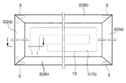
本発明のパネルは、居室の内装面に敷設され且つ温水または冷水の循環によって居室の温度調節を行うパネルであり、図2に示す様に、平面形状を四角形に形成され且つ内部に水循環路(通水管13)が設けられたパネル本体1と、パネル本体1の四辺部に付設された縦横の枠部材2とから主に構成されている。   The panel of the present invention is a panel that is laid on the interior surface of the room and adjusts the temperature of the room by circulating hot water or cold water. As shown in FIG. The main body is mainly composed of a panel main body 1 provided with a water flow pipe 13) and vertical and horizontal frame members 2 attached to four sides of the panel main body 1.

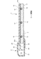
パネル本体1の平面形状は、通常、1辺が200〜3000mm程度の長方形または正方形に形成されている。図1に示す様に、パネル本体1は、発泡樹脂成形体から成る断熱材としての板状基材11と、当該板状基材の表側の溝12に配置された水循環路としての通水管13と、板状基材11の表側表面に貼着された放熱シート14と、当該放熱シートの表側に配置された意匠パネル15とから主として構成されている。そして、暖房用として使用する場合には、給湯装置(図示省略)から供給した温水を通水管13に循環させることにより、温水の熱を放熱シート14によって拡散し且つ意匠パネル15に伝達する様になされている。また、冷房用として使用する場合には、冷水製造装置(図示省略)から供給した冷水を通水管13に循環させることにより、冷水の冷熱を放熱シート14によって拡散し且つ室内に放出する様になされている。すなわち、室内側の温熱を放熱シート14によって吸収する様になされている。   The planar shape of the panel main body 1 is usually formed in a rectangle or a square having a side of about 200 to 3000 mm. As shown in FIG. 1, the panel body 1 includes a plate-like base material 11 as a heat insulating material made of a foamed resin molded body, and a water pipe 13 as a water circulation path arranged in a groove 12 on the front side of the plate-like base material. And a heat radiation sheet 14 attached to the front surface of the plate-like substrate 11 and a design panel 15 disposed on the front side of the heat radiation sheet. And when using for heating, circulating the hot water supplied from the hot water supply device (not shown) through the water pipe 13 so that the heat of the hot water is diffused by the heat radiating sheet 14 and transmitted to the design panel 15. Has been made. When used for cooling, the cold water supplied from a cold water production apparatus (not shown) is circulated through the water pipe 13 so that the cold heat of the cold water is diffused by the heat radiating sheet 14 and released into the room. ing. That is, the indoor heat is absorbed by the heat dissipation sheet 14.

板状基材11は、平面形状を例えば細長の長方形に形成された厚さ7〜20mm程度の薄板状の発泡樹脂成形体の小片を多数配列して構成されている。発泡樹脂成形体としては、硬質ポリウレタン発泡体、硬質ポリエチレン発泡体、硬質ポリプロピレン発泡体、ポリスチレン発泡体、ポリスチレンとポリエチレン混合物の発泡体などが使用されている。なお、図示しないが、板状基材11には、外部からの加圧力(意匠パネル15への衝撃)に対する強度を高めるため、木材または硬質発泡樹脂から成る幅40〜50mm程度の小割り状の根太状部材が所定の間隔で平行に挿入されていてもよい。   The plate-like base material 11 is configured by arranging a large number of small pieces of a thin plate-like foamed resin molded body having a thickness of about 7 to 20 mm and having a planar shape formed into, for example, an elongated rectangle. As the foamed resin molding, a hard polyurethane foam, a hard polyethylene foam, a hard polypropylene foam, a polystyrene foam, a foam of a mixture of polystyrene and polyethylene, and the like are used. Although not shown in the drawings, the plate-like base material 11 has a small shape with a width of about 40 to 50 mm made of wood or hard foamed resin in order to increase the strength against external pressure (impact on the design panel 15). The joist members may be inserted in parallel at predetermined intervals.

通水管13は、放熱シート14に接触する状態で溝12に配置されている。通水管13としては、外径4〜10mm、内径4〜7mmの架橋ポリエチレン管、ポリブテン管、ポリプロピレン管、ポリエチレン管などの樹脂管が使用されている。また、パネル上面側への出力を高め且つ放熱効率を高めるため、通水管13の少なくとも一部分、例えば直線部は、その長さ方向に直交する断面がU字状に形成された樋状の金属製伝熱部材(図示省略)に収容されて上記の溝12に配置されていてもよい。   The water conduit 13 is disposed in the groove 12 so as to be in contact with the heat dissipation sheet 14. As the water flow pipe 13, a resin pipe such as a cross-linked polyethylene pipe, a polybutene pipe, a polypropylene pipe, or a polyethylene pipe having an outer diameter of 4 to 10 mm and an inner diameter of 4 to 7 mm is used. Further, in order to increase the output to the panel upper surface side and increase the heat dissipation efficiency, at least a part of the water conduit 13, for example, the straight portion, is made of a bowl-shaped metal having a U-shaped cross section perpendicular to the length direction. It may be accommodated in a heat transfer member (not shown) and disposed in the groove 12.

図2においては、構造説明を簡単にするために、水循環路が1系統のパネルを例示しているが、通常、水循環路は、板状基材11の両端部で通水管13を多数回折り返すパターンで4〜12系統設けられている。その場合、板状基材11の例えば1つ端部近傍には、切込み構造のヘッダー取付部が設けられ、各通水管13は、当該ヘッダー取付部に配置された水分配回収用のヘッダー(図示省略)に繋ぎ込まれている。そして、各通水管13は、10〜50mm程度の配列ピッチで配列されている。上記の様に、ヘッダーを使用して水循環路を複数系統設けることにより、更に、通水管13を所定ピッチで配列することにより、各系統における温水または冷水の温度変化を少なくしてパネル全体で均一に放熱し且つ出力を高めることが出来る。   In FIG. 2, in order to simplify the structure description, a panel with a single water circulation path is illustrated. However, the water circulation path is usually diffracted by a large number of water pipes 13 at both ends of the plate-like substrate 11. 4 to 12 systems are provided in a pattern. In that case, for example, in the vicinity of one end of the plate-like base material 11, a header mounting portion having a cut structure is provided, and each water pipe 13 is a water distribution / recovery header (illustrated) disposed in the header mounting portion. (Omitted). And each water pipe 13 is arranged with the arrangement pitch of about 10-50 mm. As described above, by providing a plurality of water circulation paths using headers, and by arranging the water pipes 13 at a predetermined pitch, the temperature change in the hot water or cold water in each system is reduced and the entire panel is uniform. The heat can be dissipated and the output can be increased.

図1では誇張して示されているが、放熱シート14は、厚さが通常は10〜200μm、好ましくは30〜100μmの熱伝導性に優れた可撓性のフィルム又はシート、例えば、アルミニウム箔、錫箔、銅箔、ステンレス鋼箔などの金属箔や金属製の織布や不織布で構成されている。放熱シート14は、板状基材11の表面に粘着剤や接着剤フィルム等によって貼着されている。   Although exaggerated in FIG. 1, the heat-dissipating sheet 14 is a flexible film or sheet having a thickness of usually 10 to 200 μm, preferably 30 to 100 μm and excellent in thermal conductivity, such as an aluminum foil. It is made of metal foil such as tin foil, copper foil, stainless steel foil, or metal woven or non-woven fabric. The heat dissipation sheet 14 is adhered to the surface of the plate-like substrate 11 with an adhesive, an adhesive film, or the like.

意匠パネル15は、板状基材11や放熱シート14を保護し且つ意匠性を高めるため、放熱シート14の表側に配置されている。意匠パネル15は、放熱シート14から効率よく熱を伝達するために放熱シート14に接触した状態に配置されるが、当該意匠パネルだけを独立して着脱できる様に、放熱シート14から切り離された状態、すなわち、放熱シート14に貼着されていない状態で設けられている。なお、図1は、構造を明確に示すために、放熱シート14と意匠パネル15を離した状態で記載したものである。   The design panel 15 is arranged on the front side of the heat dissipation sheet 14 in order to protect the plate-like substrate 11 and the heat dissipation sheet 14 and to improve the design. The design panel 15 is disposed in contact with the heat dissipation sheet 14 in order to efficiently transfer heat from the heat dissipation sheet 14, but is separated from the heat dissipation sheet 14 so that only the design panel can be attached and detached independently. It is provided in a state that is not attached to the heat dissipation sheet 14. Note that FIG. 1 is shown in a state where the heat radiation sheet 14 and the design panel 15 are separated in order to clearly show the structure.

また、意匠パネル15は、後述する枠部材2の回り縁22と支え縁23の隙間にパネル本体1を挟持し、かつ、板状基材11や放熱シート14の損傷を防止するため、前述の放熱シート14及び板状基材11よりも広面積に形成されている。すなわち、意匠パネル15は、板状基材11から外側に幾分はみ出す大きさに形成されている。   The design panel 15 holds the panel body 1 in a gap between a peripheral edge 22 and a support edge 23 of the frame member 2 to be described later, and prevents the plate-like substrate 11 and the heat dissipation sheet 14 from being damaged. It is formed in a larger area than the sheet 14 and the plate-like substrate 11. That is, the design panel 15 is formed in a size that protrudes somewhat outward from the plate-like substrate 11.

意匠パネル15は、金属や樹脂の薄板で構成されていてもよいが、例えば、厚さ0.8〜1.5mm程度の複合板で構成されている。斯かる複合板としては、金属シート/樹脂シート/金属シートの層構成を備えた複合板が挙げられる。上記の金属シートには、アルミニウム、ステンレス、鉄、銅、チタン、錫、ニッケル等の金属または各種の合金から成る厚さ0.1〜0.2mm程度のシートが使用され、芯材の樹脂シートには、ポリエチレン、ポリプロピレン等のポリオレフィン、ポリ塩化ビニル、ポリアミド、ポリカーボネート、ポリスチレン、ポリヒドロキシルエーテル、酢酸ビニル等の熱可塑性樹脂から成る厚さ0.7〜1.0mm程度のシートが使用される。   The design panel 15 may be made of a thin plate of metal or resin, but is made of a composite plate having a thickness of about 0.8 to 1.5 mm, for example. Examples of such a composite plate include a composite plate having a layer structure of metal sheet / resin sheet / metal sheet. As the metal sheet, a sheet having a thickness of about 0.1 to 0.2 mm made of a metal such as aluminum, stainless steel, iron, copper, titanium, tin, nickel, or various alloys is used. A sheet having a thickness of about 0.7 to 1.0 mm made of a thermoplastic resin such as polyolefin such as polyethylene or polypropylene, polyvinyl chloride, polyamide, polycarbonate, polystyrene, polyhydroxyl ether, or vinyl acetate is used.

上記の様な複合板としては、例えば、ポリエチレン製芯材シートの両面にアルミニウムシートを積層して成る三菱樹脂社製の「アルポリック」(商品名)が好適であり、斯かる複合板によって意匠パネル15を構成した場合には、意匠パネル15を一層薄くして軽量化を図ることが出来かつ十分か熱伝導率を確保できる。また、意匠パネル15の表面は、印刷を含む塗装、フィルムコーティング、研磨仕上などによって意匠面として構成され、斯かる意匠面には、写真画像、絵柄、幾何学模様などが描かれていてもよい。更に、上記の意匠面は、幾何学的な凹凸模様、植物や自然を模った凹凸模様などの立体的意匠面に構成されていてもよい。   As such a composite plate, for example, “Alpolic” (trade name) manufactured by Mitsubishi Plastics, in which aluminum sheets are laminated on both sides of a polyethylene core material sheet, is suitable. 15 is configured, the design panel 15 can be further thinned to reduce the weight, and sufficient or sufficient thermal conductivity can be secured. Further, the surface of the design panel 15 is configured as a design surface by painting including coating, film coating, polishing finish, or the like, and a photographic image, a pattern, a geometric pattern, or the like may be drawn on the design surface. . Further, the design surface may be configured as a three-dimensional design surface such as a geometric uneven pattern, an uneven pattern imitating plants or nature.

図2に示す様に、パネル本体1の外周部は、縦横の枠部材2で囲まれており、縦横の枠部材2は、パネル本体1の角部に配置されたコーナー部材3で連結されている。図2中、符号2aが縦の枠部材を示し、符号2bが横の枠部材を示しており、これら縦横の枠部材2は、通常、アルミニウムの押出し型材で構成されている。枠部材2の幅は20〜30mm程度、パネル本体1の厚さに対応する枠部材2の厚さは10〜22mm程度に設計されている。枠部材2の表面は、塗装、フィルムコーティング、研磨仕上などによって意匠面として構成されている。   As shown in FIG. 2, the outer peripheral portion of the panel main body 1 is surrounded by vertical and horizontal frame members 2, and the vertical and horizontal frame members 2 are connected by corner members 3 arranged at corners of the panel main body 1. Yes. In FIG. 2, reference numeral 2 a indicates a vertical frame member, and reference numeral 2 b indicates a horizontal frame member. These vertical and horizontal frame members 2 are usually made of an extruded mold member of aluminum. The width of the frame member 2 is designed to be about 20 to 30 mm, and the thickness of the frame member 2 corresponding to the thickness of the panel body 1 is designed to be about 10 to 22 mm. The surface of the frame member 2 is configured as a design surface by painting, film coating, polishing finish, or the like.

図1に示す様に、縦横の枠部材2は、柱構造の剛体部21の表面に沿ってパネル本体1側に張出されて意匠パネル15の表面にあてがわれる回り縁22を備えている。具体的には、枠部材2は、柱構造、例えば略角パイプ状の中空柱構造の剛体部21と、当該剛体部の表面(図1における上面)及び背面(図1における下面)に沿ってパネル本体1側に回り縁22、24を各張出して構成されている。図に例示した剛体部21は、長手方向に直交する断面が略方形の管状に形成され、その表面(図1における上面)の一部は、意匠上の観点から、外側(パネル本体1と反対側)に向かうに従い漸次低くなる傾斜面に形成されている。符号2pは、枠部材2の両端部において開口する剛体部21の中空部を示している。   As shown in FIG. 1, the vertical and horizontal frame members 2 are provided with a peripheral edge 22 that is projected to the panel body 1 side along the surface of the columnar rigid portion 21 and applied to the surface of the design panel 15. Specifically, the frame member 2 has a columnar structure, for example, a rigid body portion 21 of a hollow columnar structure having a substantially square pipe shape, and a surface (upper surface in FIG. 1) and a rear surface (lower surface in FIG. 1) of the rigid body portion. Each of the peripheral edges 22 and 24 is extended to the panel body 1 side. The rigid body portion 21 illustrated in the figure is formed in a tubular shape having a substantially rectangular cross section perpendicular to the longitudinal direction, and a part of the surface (upper surface in FIG. 1) is the outer side (opposite of the panel body 1) from the viewpoint of design. It is formed in the inclined surface which becomes gradually low as it goes to the side. Reference numeral 2 p indicates a hollow portion of the rigid portion 21 that opens at both ends of the frame member 2.

また、表面側の回り縁22の先端縁には、意匠パネル15の表面と見切りをつけて意匠性を高め且つ安全性を確保するため、屈曲部22cが設けられている。表面側の回り縁22の張出し長さは、背面側の回り縁24の張出し長さの60〜85%に相当する長さに設定されている。そして、設置、メンテナンス、模様替え等の際に意匠パネル15の着脱を容易にするため、パネル本体1は、その外周部を枠部材2の2つの回り縁22、24によって挟持されている。   In addition, a bent portion 22c is provided at the front end edge of the peripheral edge 22 on the front surface side in order to cut off the surface of the design panel 15 to enhance design properties and ensure safety. The overhang length of the peripheral edge 22 on the front surface side is set to a length corresponding to 60 to 85% of the overhang length of the peripheral edge 24 on the back surface side. The panel body 1 is sandwiched between the two peripheral edges 22 and 24 of the frame member 2 in order to facilitate the attachment and detachment of the design panel 15 during installation, maintenance, pattern change, and the like.

更に、各枠部材2には、剛体部21から張出された2つの回り縁22、24の間に更にパネル本体1の意匠パネル15を裏面から支持する支え縁23が張出されている。支え縁23の張出し長さは、上記の様なメンテナンス等における施工性を考慮し、表面側の回り縁22よりも更に短い長さに設計されている。しかも、支え縁23は、パネル本体1における板状基材11から放熱シート14までの厚さ相当する距離だけ背面側の回り縁24から離間した位置に設けられている。   Furthermore, a support edge 23 is further extended from each frame member 2 between the two peripheral edges 22 and 24 extended from the rigid portion 21 to support the design panel 15 of the panel body 1 from the back surface. The overhang length of the support edge 23 is designed to be shorter than the peripheral edge 22 on the surface side in consideration of the workability in the maintenance as described above. In addition, the support edge 23 is provided at a position separated from the peripheral edge 24 on the back side by a distance corresponding to the thickness from the plate-like base material 11 to the heat dissipation sheet 14 in the panel body 1.

すなわち、パネル本体1の意匠パネル15以外の部位、換言すれば、通水管13や放熱シート14を含む板状基材11は、背面側の回り縁24と支え縁23との間に収められ、意匠パネル15は、その周縁を回り縁22と支え縁23の隙間に収められている。上記の様に、意匠パネル15の周縁が回り縁22と支え縁23の隙間に収められた構造にいては、意匠パネル15に外側から力が加えられた場合でも、これを支え縁23で支持できるため、パネル本体1の板状基材11、通水管13および放熱シート14を一層確実に保護することが出来る。   That is, the part other than the design panel 15 of the panel body 1, in other words, the plate-like base material 11 including the water pipe 13 and the heat radiating sheet 14 is stored between the peripheral edge 24 and the support edge 23 on the back side. The panel 15 is housed in a gap between the peripheral edge 22 and the support edge 23 around the periphery. As described above, in the structure in which the peripheral edge of the design panel 15 is accommodated in the gap between the rotating edge 22 and the support edge 23, even when a force is applied to the design panel 15 from the outside, it can be supported by the support edge 23. Therefore, the plate-like base material 11, the water pipe 13 and the heat radiating sheet 14 of the panel body 1 can be more reliably protected.

また、枠部材2は、回り縁22及び支え縁23の張出し長さの設定により、図1に示す様に、回り縁22と支え縁23で意匠パネル15を挟持した状態において、意匠パネル15の端部の外周側に隙間20が形成される様に構成されている。隙間20の大きさ、すなわち、回り縁22と支え縁23の間隙の奥探から意匠パネル15の端部までの距離(図1において隙間20の左右方向の長さ)は、当該距離方向に沿った意匠パネル15の長さ1mに対して1〜3mm程度の割合で設定されている。枠部材2の内部に上記の様な隙間20を設けることにより、例えば暖房時にパネル本体1に80℃の温水を循環させた場合でも、意匠パネル15の伸縮に対応することが出来る。   Further, the frame member 2 has an end portion of the design panel 15 in a state in which the design panel 15 is sandwiched between the peripheral edge 22 and the support edge 23 as shown in FIG. It is comprised so that the clearance gap 20 may be formed in the outer peripheral side. The size of the gap 20, that is, the distance from the back of the gap between the peripheral edge 22 and the support edge 23 to the end of the design panel 15 (the length in the horizontal direction of the gap 20 in FIG. 1) is along the distance direction. It is set at a ratio of about 1 to 3 mm with respect to the length 1 m of the design panel 15. By providing the gap 20 as described above inside the frame member 2, for example, even when warm water of 80 ° C. is circulated through the panel body 1 during heating, the design panel 15 can be expanded and contracted.

上記の様な縦横の枠部材2は、平面形状をL字状に形成されたコーナー部材3で連結されている。コーナー部材3は、枠部材2の剛体部21の端部開口に対応して、長さ方向に直交する断面が略方形に形成されたバーをL字状に屈曲させた形状を備えており、隣接する枠部材2a、2bの各中空部2pに挿入する様になされている。なお、コーナー部材3は、枠部材2aと枠部材2bを連結し得る限り、各種の形状に設計できる。例えば、長さ方向に直交して切断された形状の両端部を備えた縦横の枠部材に適用するため、コーナー部材3は、縦横の枠部材の交差部分の空隙をうめる構造を備えていてもよく、また、コーナー部材自体を利用して内装面にパネルを取り付けるため、内装面固定用のねじ装着穴を有していてもよい。   The vertical and horizontal frame members 2 as described above are connected by a corner member 3 having a planar shape formed in an L shape. The corner member 3 has a shape in which a bar having a substantially square cross section perpendicular to the length direction is bent in an L shape corresponding to the end opening of the rigid body portion 21 of the frame member 2. It is made to insert in each hollow part 2p of adjacent frame member 2a, 2b. The corner member 3 can be designed in various shapes as long as the frame member 2a and the frame member 2b can be connected. For example, in order to apply to a vertical and horizontal frame member having both ends of a shape cut perpendicular to the length direction, the corner member 3 may have a structure that fills the gap at the intersection of the vertical and horizontal frame members. Moreover, in order to attach the panel to the interior surface using the corner member itself, it may have a screw mounting hole for fixing the interior surface.

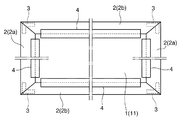
本発明においては、模様替えやメンテナンスの際、意匠パネル15だけを簡単に着脱するため、パネル本体1は、板状基材11の背面が枠部材2に固定されている。好ましくは、パネル本体1は、板状基材11の背面が枠部材2の背面側の回り縁24に固定されている。枠部材2の回り縁24に対する板状基材11の固定方法としては、回り縁24内面または板状基材11の周縁部背面側に接着剤や粘着材を添付する方法、回り縁24から板状基材11の背面にピン状の部材を突き刺す方法などが挙げられるが、組立時の施工性、模様替え等における取扱性を高める観点からは、図3に示す様に、テープ4による固定方法が好ましい。   In the present invention, the panel body 1 has the back surface of the plate-like base material 11 fixed to the frame member 2 so that only the design panel 15 can be easily attached and detached during pattern change or maintenance. Preferably, in the panel body 1, the back surface of the plate-like substrate 11 is fixed to the peripheral edge 24 on the back surface side of the frame member 2. As a method for fixing the plate-like base material 11 to the peripheral edge 24 of the frame member 2, a method of attaching an adhesive or a pressure-sensitive adhesive to the inner surface of the peripheral edge 24 or the peripheral portion back side of the plate-like base material 11, 11 is a method of piercing a pin-like member on the back surface, but from the viewpoint of improving workability during assembly and handling in pattern change, a fixing method using a tape 4 is preferable as shown in FIG.

具体的には、図1に示す様に、板状基材11の背面は、枠部材2の背面側の回り縁24から当該板状基材の背面に架け渡して貼着されたテープ4により固定されている。テープ4としては、基材フィルム又は基材シートの一面に粘着剤層が設けられたテープが使用される。テープ4の基材のフィルム又はシートとしては、ポリエチレンやポリエチレンテレフタレート等が挙げられる。また、粘着剤としては、アクリル樹脂やブチルゴム等が挙げられる。   Specifically, as shown in FIG. 1, the back surface of the plate-like base material 11 is fixed by a tape 4 that is pasted from the peripheral edge 24 on the back side of the frame member 2 to the back surface of the plate-like base material. Has been. As the tape 4, a tape in which an adhesive layer is provided on one surface of a base film or a base sheet is used. Examples of the base film or sheet of the tape 4 include polyethylene and polyethylene terephthalate. Examples of the adhesive include acrylic resin and butyl rubber.

本発明のパネルにおいては、上記の様なテープ4を使用することにより、板状基材11と枠部材2とを簡単に固定でき、また、簡単に分離できるため、板状基材11と枠部材2を固定する態様として、幾つかの態様を採用できる。例えば、図3に示す様に、パネル本体1の板状基材11は、上記のテープ4により、縦横の各枠部材2に固定されている。図3に示す様に板状基材11の4辺部を枠部材2に固定した場合には、パネルの全体形状が確実に保持されるため、パネルの設置や設置までの取扱いが容易である。   In the panel of the present invention, the plate-like base material 11 and the frame member 2 can be easily fixed and easily separated by using the tape 4 as described above. Several modes can be adopted as modes for fixing the member 2. For example, as shown in FIG. 3, the plate-like substrate 11 of the panel main body 1 is fixed to the vertical and horizontal frame members 2 by the tape 4. As shown in FIG. 3, when the four sides of the plate-like substrate 11 are fixed to the frame member 2, the entire shape of the panel is securely held, so that the panel can be easily installed and handled. .

また、パネル本体1の板状基材11は、上記のテープ4により、一対の縦の枠部材2aまたは一対の横の枠部材2bに固定されていてもよい。換言すれば、パネル本体1の縦または横の1組の平行な2辺部においては、テープ4により板状基材11と枠部材2とが締結されており、パネル本体1の他の1組の平行な2辺部においては、板状基材11と枠部材2が締結されていない状態、すなわち、パネル本体1の縁部が枠部材2で挟持されただけの状態になされている。板状基材11の2辺部を枠部材2に固定した場合には、板状基材11に締結されていない何れか1つの枠部材2をそのまま外せるため、意匠パネル15の着脱が一層容易である。   Further, the plate-like substrate 11 of the panel body 1 may be fixed to the pair of vertical frame members 2a or the pair of horizontal frame members 2b by the tape 4 described above. In other words, the plate-like base material 11 and the frame member 2 are fastened by the tape 4 at one set of two parallel sides of the panel main body 1 in the vertical or horizontal direction. In the two parallel sides, the plate-like base material 11 and the frame member 2 are not fastened, that is, the edge of the panel body 1 is simply held between the frame members 2. When the two side portions of the plate-like base material 11 are fixed to the frame member 2, any one frame member 2 that is not fastened to the plate-like base material 11 can be removed as it is, so that the design panel 15 can be easily attached and detached. It is.

本発明のパネルは、以下の様にして取り扱われる。すなわち、本発明のパネルを設置する場合には、例えば、温水供給・回収用の1組の連絡配管を給湯装置から壁面の所定位置まで引き回した後、パネルの通水管13基端のヘッダーに連絡配管を接続し、次いで、コーナー部材または支持金物を利用し、ねじによって壁面にパネルを固定する。   The panel of the present invention is handled as follows. That is, when the panel of the present invention is installed, for example, a set of connecting pipes for supplying and collecting hot water is routed from the hot water supply device to a predetermined position on the wall surface, and then connected to the header at the base end of the water pipe 13 of the panel. Pipes are connected, and then the panel is fixed to the wall surface with screws using corner members or support hardware.

一方、模様替えやメンテナンスのために意匠パネル15を取り外すには、先ず、固定用のねじを一部外してパネルを壁面から幾分浮かせるか、あるいは、固定用のねじを全て外してパネルを壁面から取り外し、次いで、所定の枠部材2を取り外す。   On the other hand, in order to remove the design panel 15 for pattern change or maintenance, first remove some fixing screws and lift the panel somewhat from the wall surface, or remove all fixing screws and remove the panel from the wall surface. Next, the predetermined frame member 2 is removed.

具体的には、パネル本体1の板状基材11の背面が4辺部において枠部材2の回り縁24に固定されている場合には、意匠パネル15を引き出し易い側のテープ4を剥し、剥した部分の1つの枠部材2を取り外す。また、板状基材11の背面が2辺部において回り縁24に固定されている場合には、固定されていない側で且つ意匠パネル15を引き出し易い側の1つの枠部材2を取り外す。これにより、意匠パネル15をスライドさせて当該意匠パネルだけを取り外し、新たな意匠パネル15を逆の手順で差し込むことが出来る。   Specifically, when the back surface of the plate-like substrate 11 of the panel body 1 is fixed to the peripheral edge 24 of the frame member 2 at the four sides, the tape 4 on the side on which the design panel 15 is easily pulled out is peeled off. One frame member 2 of the part made is removed. Moreover, when the back surface of the plate-like base material 11 is fixed to the peripheral edge 24 at the two sides, one frame member 2 on the side that is not fixed and on which the design panel 15 can be easily pulled out is removed. Thereby, the design panel 15 can be slid, only the said design panel is removed, and the new design panel 15 can be inserted in a reverse procedure.

上記の様に、本発明においては、板状基材11側から意匠パネル15が独立しており、そして、枠部材2の回り縁22、24によってパネル本体1の外周部が挟持され且つパネル本体1の板状基材11の背面が枠部材2の背面側の回り縁24に固定されているため、1箇所の枠部材2を取り外すだけで、意匠パネル15だけをスライドさせて着脱することが出来る。従って、室内の模様替えやメンテナンスを極めて容易に行うことが出来る。   As described above, in the present invention, the design panel 15 is independent from the plate-like base material 11 side, and the outer peripheral portion of the panel body 1 is sandwiched between the peripheral edges 22 and 24 of the frame member 2 and the panel body 1 Since the back surface of the plate-like base material 11 is fixed to the peripheral edge 24 on the back surface side of the frame member 2, only the design panel 15 can be slid and attached by simply removing the frame member 2 at one location. Therefore, it is very easy to change the interior and maintain the room.

1 :パネル本体
11:板状基材(断熱材)
12:溝
13:通水管(水循環路)
14:放熱シート
15:意匠パネル
2 :枠部材
2a:枠部材(縦)
2b:枠部材(横)
2p:中空部
20:隙間
21:剛体部
22:回り縁(表面側)
23:支え縁
24:回り縁(背面側)
3 :コーナー部材
4 :テープ
1: Panel body 11: Plate base material (heat insulating material)
12: Groove 13: Water pipe (water circulation path)
14: Heat dissipation sheet 15: Design panel 2: Frame member 2a: Frame member (vertical)
2b: Frame member (horizontal)
2p: hollow part 20: gap 21: rigid part 22: peripheral edge (surface side)
23: Support edge 24: Circumference edge (back side)
3: Corner member 4: Tape

Claims (6)

居室の内装面に敷設され且つ温水または冷水の循環によって居室の温度調節を行う放熱パネルであって、平面形状を四角形に形成され且つ内部に水循環路が設けられたパネル本体と、当該パネル本体の四辺部に付設された縦横の枠部材とを備え、かつ、パネル本体は、断熱材としての板状基材と、当該板状基材の表側の溝に配置された水循環路としての通水管と、板状基材の表面に貼着された放熱シートと、当該放熱シートの表側に配置された意匠パネルとから構成されており、縦横の枠部材は、柱構造の剛体部の表面に沿ってパネル本体側に張出された回り縁を備え、パネル本体は、板状基材の背面が枠部材に固定されていることを特徴とする放熱パネル。   A heat dissipating panel that is laid on the interior surface of a room and adjusts the temperature of the room by circulation of hot water or cold water, the panel body having a square shape and a water circulation path inside, and a panel body The panel body includes a plate-like base material as a heat insulating material, and a water pipe as a water circulation path disposed in a groove on the front side of the plate-like base material. The heat-dissipating sheet is attached to the surface of the plate-like base material, and the design panel is arranged on the front side of the heat-dissipating sheet. The vertical and horizontal frame members extend along the surface of the rigid part of the column structure. A heat dissipating panel comprising a peripheral edge extending to the panel body side, wherein the panel body has a back surface of a plate-like substrate fixed to a frame member. 縦横の枠部材は、柱構造の剛体部の表面および背面に沿ってパネル本体側に回り縁を各張出して構成され、パネル本体は、その外周部を枠部材の2つの回り縁によって挟持され、かつ、板状基材の背面が枠部材の背面側の回り縁に固定されている請求項1に記載の放熱パネル。   The vertical and horizontal frame members are each configured to project a peripheral edge toward the panel main body along the front and back surfaces of the rigid portion of the column structure, and the panel main body is sandwiched by two peripheral edges of the frame member, and The heat dissipation panel according to claim 1, wherein the back surface of the plate-like base material is fixed to the peripheral edge on the back surface side of the frame member. 板状基材の背面が、枠部材の背面側の回り縁から当該板状基材の背面に架け渡して貼着されたテープにより固定されている請求項2に記載の放熱パネル。   The heat dissipation panel according to claim 2, wherein the back surface of the plate-like base material is fixed by a tape that is pasted from the peripheral edge on the back side of the frame member to the back surface of the plate-like base material. パネル本体の板状基材は、一対の縦または横の枠部材に固定されている請求項1〜3の何れかに記載の放熱パネル。   The heat dissipation panel according to any one of claims 1 to 3, wherein the plate-like substrate of the panel body is fixed to a pair of vertical or horizontal frame members. 各枠部材には、剛体部から張出された2つの回り縁の間に更に意匠パネルを裏面から支持する支え縁が張出され、意匠パネルは、その周縁を表面側の回り縁と支え縁との隙間に収められている請求項2〜4の何れかに記載の放熱パネル。   In each frame member, a support edge for supporting the design panel from the back surface is further extended between two peripheral edges extending from the rigid body portion. The design panel has a peripheral edge formed between the peripheral edge and the support edge on the front side. The heat dissipation panel according to any one of claims 2 to 4, which is housed in a gap. 意匠パネルの表面は、写真画像、絵柄、幾何学模様または凹凸模様が描かれた意匠面として構成されている請求項1〜5の何れかに記載の放熱パネル。   The heat dissipation panel according to any one of claims 1 to 5, wherein the surface of the design panel is configured as a design surface on which a photographic image, a picture, a geometric pattern, or an uneven pattern is drawn.
JP2009192705A 2009-08-24 2009-08-24 Heat dissipation panel Expired - Fee Related JP5338564B2 (en)

Priority Applications (1)

Application Number Priority Date Filing Date Title
JP2009192705A JP5338564B2 (en) 2009-08-24 2009-08-24 Heat dissipation panel

Applications Claiming Priority (1)

Application Number Priority Date Filing Date Title
JP2009192705A JP5338564B2 (en) 2009-08-24 2009-08-24 Heat dissipation panel

Publications (2)

Publication Number Publication Date
JP2011043303A JP2011043303A (en) 2011-03-03
JP5338564B2 true JP5338564B2 (en) 2013-11-13

Family

ID=43830857

Family Applications (1)

Application Number Title Priority Date Filing Date
JP2009192705A Expired - Fee Related JP5338564B2 (en) 2009-08-24 2009-08-24 Heat dissipation panel

Country Status (1)

Country Link
JP (1) JP5338564B2 (en)

Families Citing this family (4)

* Cited by examiner, † Cited by third party
Publication number Priority date Publication date Assignee Title
CN103822318B (en) * 2012-11-19 2017-04-12 珠海格力电器股份有限公司 Radiant heat exchange plate component
JP6208456B2 (en) * 2013-04-09 2017-10-04 株式会社ササクラ Radiant panel and manufacturing method thereof
CN106016425B (en) * 2016-05-15 2021-06-25 夏维月 Electric heater
CN107289501B (en) * 2017-08-08 2023-03-14 合肥恒暖暖通设备有限公司 Wall radiator

Family Cites Families (4)

* Cited by examiner, † Cited by third party
Publication number Priority date Publication date Assignee Title
JPS59225228A (en) * 1983-06-03 1984-12-18 Showa Alum Corp Manufacturing of floor heating panel having connection groove
JPH0440492U (en) * 1990-08-02 1992-04-06
JP3973314B2 (en) * 1999-02-24 2007-09-12 株式会社サン美術工芸 Panel heater
JP4379659B2 (en) * 2000-08-28 2009-12-09 株式会社ノーリツ Heating mat

Also Published As

Publication number Publication date
JP2011043303A (en) 2011-03-03

Similar Documents

Publication Publication Date Title
JP5338564B2 (en) Heat dissipation panel
US11595001B2 (en) Cooling element for upgrading a photovoltaic module and method for upgrading the same
JP2008309395A (en) Radiation panel for heating/cooling
JP5338563B2 (en) Heat dissipation panel
JP2010243128A (en) Radiation panel device
JP4963731B2 (en) Concealed heating / cooling system in the partition
JP2014062672A (en) Radiation panel for cooling/heating operation
JP2017026271A (en) Baseboard heating device
EP2444746A1 (en) Heating system with improved heat transfer between tubing and plates
JP2010043810A (en) Cooling/heating panel
JP2009222279A (en) Heating device
JP2002333148A (en) Floor panel
JP5609746B2 (en) Temperature control mat and temperature control structure
JP2009127984A (en) Floor heating panel and manufacturing method of the floor heating panel
JP2010112566A (en) Supporting member set and heating/cooling system
JP2008185314A (en) Operating method of floor heating system
JP6213017B2 (en) Heat-dissipating panel for non-living room
JP6340763B2 (en) Dining kitchen floor heating panel
JP6160420B2 (en) Heating and cooling panel
JP2014067152A (en) Cover and electronic device
JP2008032377A (en) Heat radiation panel for cooling and heating
JP5181577B2 (en) Groove structure for water pipe arrangement in hot water mat for floor heating
KR100585274B1 (en) a heating apparatus for bed
CN216048190U (en) Floor heating fresh air system utilizing floor heating to preheat
JPH06193914A (en) Construction of ceiling radiation type temperature regulator

Legal Events

Date Code Title Description
A621 Written request for application examination

Free format text: JAPANESE INTERMEDIATE CODE: A621

Effective date: 20120518

TRDD Decision of grant or rejection written
A01 Written decision to grant a patent or to grant a registration (utility model)

Free format text: JAPANESE INTERMEDIATE CODE: A01

Effective date: 20130709

A61 First payment of annual fees (during grant procedure)

Free format text: JAPANESE INTERMEDIATE CODE: A61

Effective date: 20130722

R150 Certificate of patent or registration of utility model

Ref document number: 5338564

Country of ref document: JP

Free format text: JAPANESE INTERMEDIATE CODE: R150

Free format text: JAPANESE INTERMEDIATE CODE: R150

S111 Request for change of ownership or part of ownership

Free format text: JAPANESE INTERMEDIATE CODE: R313111

R350 Written notification of registration of transfer

Free format text: JAPANESE INTERMEDIATE CODE: R350

LAPS Cancellation because of no payment of annual fees