JP5336512B2 - Window film attachment - Google Patents
Window film attachment Download PDFInfo
- Publication number
- JP5336512B2 JP5336512B2 JP2010539611A JP2010539611A JP5336512B2 JP 5336512 B2 JP5336512 B2 JP 5336512B2 JP 2010539611 A JP2010539611 A JP 2010539611A JP 2010539611 A JP2010539611 A JP 2010539611A JP 5336512 B2 JP5336512 B2 JP 5336512B2
- Authority
- JP
- Japan
- Prior art keywords
- window
- article
- window frame
- window film
- edge
- Prior art date
- Legal status (The legal status is an assumption and is not a legal conclusion. Google has not performed a legal analysis and makes no representation as to the accuracy of the status listed.)
- Active
Links
Images


Classifications
-
- E—FIXED CONSTRUCTIONS
- E06—DOORS, WINDOWS, SHUTTERS, OR ROLLER BLINDS IN GENERAL; LADDERS
- E06B—FIXED OR MOVABLE CLOSURES FOR OPENINGS IN BUILDINGS, VEHICLES, FENCES OR LIKE ENCLOSURES IN GENERAL, e.g. DOORS, WINDOWS, BLINDS, GATES
- E06B5/00—Doors, windows, or like closures for special purposes; Border constructions therefor
- E06B5/10—Doors, windows, or like closures for special purposes; Border constructions therefor for protection against air-raid or other war-like action; for other protective purposes
- E06B5/11—Doors, windows, or like closures for special purposes; Border constructions therefor for protection against air-raid or other war-like action; for other protective purposes against burglary
-
- B—PERFORMING OPERATIONS; TRANSPORTING
- B29—WORKING OF PLASTICS; WORKING OF SUBSTANCES IN A PLASTIC STATE IN GENERAL
- B29C—SHAPING OR JOINING OF PLASTICS; SHAPING OF MATERIAL IN A PLASTIC STATE, NOT OTHERWISE PROVIDED FOR; AFTER-TREATMENT OF THE SHAPED PRODUCTS, e.g. REPAIRING
- B29C65/00—Joining or sealing of preformed parts, e.g. welding of plastics materials; Apparatus therefor
- B29C65/48—Joining or sealing of preformed parts, e.g. welding of plastics materials; Apparatus therefor using adhesives, i.e. using supplementary joining material; solvent bonding
- B29C65/4805—Joining or sealing of preformed parts, e.g. welding of plastics materials; Apparatus therefor using adhesives, i.e. using supplementary joining material; solvent bonding characterised by the type of adhesives
- B29C65/481—Non-reactive adhesives, e.g. physically hardening adhesives
- B29C65/4815—Hot melt adhesives, e.g. thermoplastic adhesives
-
- B—PERFORMING OPERATIONS; TRANSPORTING
- B29—WORKING OF PLASTICS; WORKING OF SUBSTANCES IN A PLASTIC STATE IN GENERAL
- B29C—SHAPING OR JOINING OF PLASTICS; SHAPING OF MATERIAL IN A PLASTIC STATE, NOT OTHERWISE PROVIDED FOR; AFTER-TREATMENT OF THE SHAPED PRODUCTS, e.g. REPAIRING
- B29C65/00—Joining or sealing of preformed parts, e.g. welding of plastics materials; Apparatus therefor
- B29C65/48—Joining or sealing of preformed parts, e.g. welding of plastics materials; Apparatus therefor using adhesives, i.e. using supplementary joining material; solvent bonding
- B29C65/4805—Joining or sealing of preformed parts, e.g. welding of plastics materials; Apparatus therefor using adhesives, i.e. using supplementary joining material; solvent bonding characterised by the type of adhesives
- B29C65/481—Non-reactive adhesives, e.g. physically hardening adhesives
- B29C65/4825—Pressure sensitive adhesives
-
- B—PERFORMING OPERATIONS; TRANSPORTING
- B29—WORKING OF PLASTICS; WORKING OF SUBSTANCES IN A PLASTIC STATE IN GENERAL
- B29C—SHAPING OR JOINING OF PLASTICS; SHAPING OF MATERIAL IN A PLASTIC STATE, NOT OTHERWISE PROVIDED FOR; AFTER-TREATMENT OF THE SHAPED PRODUCTS, e.g. REPAIRING
- B29C65/00—Joining or sealing of preformed parts, e.g. welding of plastics materials; Apparatus therefor
- B29C65/48—Joining or sealing of preformed parts, e.g. welding of plastics materials; Apparatus therefor using adhesives, i.e. using supplementary joining material; solvent bonding
- B29C65/4805—Joining or sealing of preformed parts, e.g. welding of plastics materials; Apparatus therefor using adhesives, i.e. using supplementary joining material; solvent bonding characterised by the type of adhesives
- B29C65/483—Reactive adhesives, e.g. chemically curing adhesives
- B29C65/4835—Heat curing adhesives
-
- B—PERFORMING OPERATIONS; TRANSPORTING
- B29—WORKING OF PLASTICS; WORKING OF SUBSTANCES IN A PLASTIC STATE IN GENERAL
- B29C—SHAPING OR JOINING OF PLASTICS; SHAPING OF MATERIAL IN A PLASTIC STATE, NOT OTHERWISE PROVIDED FOR; AFTER-TREATMENT OF THE SHAPED PRODUCTS, e.g. REPAIRING
- B29C65/00—Joining or sealing of preformed parts, e.g. welding of plastics materials; Apparatus therefor
- B29C65/48—Joining or sealing of preformed parts, e.g. welding of plastics materials; Apparatus therefor using adhesives, i.e. using supplementary joining material; solvent bonding
- B29C65/50—Joining or sealing of preformed parts, e.g. welding of plastics materials; Apparatus therefor using adhesives, i.e. using supplementary joining material; solvent bonding using adhesive tape, e.g. thermoplastic tape; using threads or the like
- B29C65/5057—Joining or sealing of preformed parts, e.g. welding of plastics materials; Apparatus therefor using adhesives, i.e. using supplementary joining material; solvent bonding using adhesive tape, e.g. thermoplastic tape; using threads or the like positioned between the surfaces to be joined
-
- B—PERFORMING OPERATIONS; TRANSPORTING
- B29—WORKING OF PLASTICS; WORKING OF SUBSTANCES IN A PLASTIC STATE IN GENERAL
- B29C—SHAPING OR JOINING OF PLASTICS; SHAPING OF MATERIAL IN A PLASTIC STATE, NOT OTHERWISE PROVIDED FOR; AFTER-TREATMENT OF THE SHAPED PRODUCTS, e.g. REPAIRING
- B29C66/00—General aspects of processes or apparatus for joining preformed parts
- B29C66/40—General aspects of joining substantially flat articles, e.g. plates, sheets or web-like materials; Making flat seams in tubular or hollow articles; Joining single elements to substantially flat surfaces
- B29C66/41—Joining substantially flat articles ; Making flat seams in tubular or hollow articles
- B29C66/43—Joining a relatively small portion of the surface of said articles
- B29C66/434—Joining substantially flat articles for forming corner connections, fork connections or cross connections
- B29C66/4342—Joining substantially flat articles for forming corner connections, e.g. for making V-shaped pieces
- B29C66/43421—Joining substantially flat articles for forming corner connections, e.g. for making V-shaped pieces with a right angle, e.g. for making L-shaped pieces
-
- B—PERFORMING OPERATIONS; TRANSPORTING
- B29—WORKING OF PLASTICS; WORKING OF SUBSTANCES IN A PLASTIC STATE IN GENERAL
- B29C—SHAPING OR JOINING OF PLASTICS; SHAPING OF MATERIAL IN A PLASTIC STATE, NOT OTHERWISE PROVIDED FOR; AFTER-TREATMENT OF THE SHAPED PRODUCTS, e.g. REPAIRING
- B29C66/00—General aspects of processes or apparatus for joining preformed parts
- B29C66/40—General aspects of joining substantially flat articles, e.g. plates, sheets or web-like materials; Making flat seams in tubular or hollow articles; Joining single elements to substantially flat surfaces
- B29C66/41—Joining substantially flat articles ; Making flat seams in tubular or hollow articles
- B29C66/43—Joining a relatively small portion of the surface of said articles
- B29C66/434—Joining substantially flat articles for forming corner connections, fork connections or cross connections
- B29C66/4344—Joining substantially flat articles for forming fork connections, e.g. for making Y-shaped pieces
- B29C66/43441—Joining substantially flat articles for forming fork connections, e.g. for making Y-shaped pieces with two right angles, e.g. for making T-shaped pieces, H-shaped pieces
-
- B—PERFORMING OPERATIONS; TRANSPORTING
- B29—WORKING OF PLASTICS; WORKING OF SUBSTANCES IN A PLASTIC STATE IN GENERAL
- B29C—SHAPING OR JOINING OF PLASTICS; SHAPING OF MATERIAL IN A PLASTIC STATE, NOT OTHERWISE PROVIDED FOR; AFTER-TREATMENT OF THE SHAPED PRODUCTS, e.g. REPAIRING
- B29C66/00—General aspects of processes or apparatus for joining preformed parts
- B29C66/40—General aspects of joining substantially flat articles, e.g. plates, sheets or web-like materials; Making flat seams in tubular or hollow articles; Joining single elements to substantially flat surfaces
- B29C66/47—Joining single elements to sheets, plates or other substantially flat surfaces
-
- B—PERFORMING OPERATIONS; TRANSPORTING
- B29—WORKING OF PLASTICS; WORKING OF SUBSTANCES IN A PLASTIC STATE IN GENERAL
- B29L—INDEXING SCHEME ASSOCIATED WITH SUBCLASS B29C, RELATING TO PARTICULAR ARTICLES
- B29L2031/00—Other particular articles
- B29L2031/778—Windows
Abstract
Description
本発明は、全体として、窓に関し、より詳細には、窓ガラスに貼り付けられた窓用フィルムを利用する耐衝撃性窓組立体に関する。 The present invention relates generally to windows, and more particularly to an impact resistant window assembly that utilizes a film for windows attached to a window glass.
窓用フィルムは、窓の耐衝撃性及び他の性質を向上させるため、一般に、通常の窓ガラスに、例えば商業建築物又は住居の既存の窓などに貼り付けられる。このような窓用フィルムは、3M社(3M Company)(ミネソタ州セントポール(St. Paul))から、商品名3Mスコッチシールド ウルトラ・セーフティ・アンド・セキュリティ・ウィンドウ・フィルム(3M SCOTCHSHIELD Ultra Safety and Security window film)として市販されている。このような窓用フィルムは、例えば、ハリケーン及び地震などの自然現象並びに爆発及び「窓破り(smash-and-grab)」窃盗などの人為的事象に対する保護をもたらす。 Window films are generally affixed to conventional window glass, such as existing windows in commercial buildings or residences, to improve the impact resistance and other properties of the window. Such window films are available from 3M Company (St. Paul, MN) under the trade name 3M SCOTCHSHIELD Ultra Safety and Security. window film). Such window films provide protection against natural phenomena such as, for example, hurricanes and earthquakes, as well as man-made events such as explosions and “smash-and-grab” theft.
窓用フィルムは窓ガラスに接着剤で固着され、窓用フィルムの縁部は、シリコーンシーラントを使用して窓枠に固定される。シリコーンシーラントは、窓用フィルムの縁部に沿って、又は窓枠の隣接した縁部分に沿って塗布される。窓ガラスに衝撃が加えられた場合、窓用フィルムは粉々になったガラスを所定の位置に保持する。即ち、ガラスの粉々になった破片は、一般に、衝撃の後、窓用フィルムに接着したままである。シリコーンシーラントは、同様に、窓用フィルム及び接着した粉々になったガラスを窓枠に保持する働きをする。窓の開口部内に粉々になったガラスを保持することによって、窓用フィルムは、飛散したガラスが建物の中に居る人々を負傷させる可能性を低減し、また、風や雨が構造物の内部に入り込み、損害を与えるのを防いでいる。 The window film is fixed to the window glass with an adhesive, and the edge of the window film is fixed to the window frame using a silicone sealant. The silicone sealant is applied along the edge of the window film or along the adjacent edge portion of the window frame. When an impact is applied to the window glass, the window film holds the shattered glass in place. That is, broken glass pieces generally remain adhered to the window film after impact. The silicone sealant also serves to hold the window film and adhered shattered glass to the window frame. By holding shattered glass in the window openings, the window film reduces the possibility of splashed glass injuring people in the building, and wind and rain are inside the structure. It prevents it from getting in and damaging it.
窓用フィルムを窓枠に固定するための物品は、従来技術において既知である。例えば、米国特許第5,992,107号(ポワリエ(Poirier))は、窓枠内で縁部にはめ込む安全窓用フィルムの方法及び装置を開示している。米国特許第6,931,799号(ウェッブ(Webb))は、枠内にはめ込まれ、窓用フィルムによって衝撃に対して保護された窓ガラスを固定する定着プロファイルを開示している。 Articles for fixing window films to window frames are known in the prior art. For example, U.S. Pat. No. 5,992,107 (Poirier) discloses a method and apparatus for a safety window film that fits into an edge within a window frame. U.S. Pat. No. 6,931,799 (Webb) discloses a fixing profile that secures a window glass that is fitted into a frame and protected against impact by a window film.
当該業界は、改善された耐衝撃性の窓構造物、並びに窓用フィルムを窓枠によりしっかりと取り付けるための改善された物品及び方法を常に模索している。衝撃に対する改善された保護を提供し、コスト効率が良く、より迅速又は簡単に設置することができる、窓ガラスに貼り付けられた窓用フィルムを利用する改善された耐衝撃性の窓構造物が、継続的に必要とされている。本発明は、窓用フィルムを窓枠に固定するための改善された物品、並びに改善された衝撃性能(impact performance)を発揮する改善された耐衝撃性窓用フィルム組立体を提供する。 The industry is constantly looking for improved impact resistant window structures, and improved articles and methods for attaching window films more securely to window frames. An improved impact resistant window structure utilizing a window film affixed to a glazing that provides improved protection against impact, is cost effective, and can be installed more quickly or easily. Continually needed. The present invention provides an improved article for securing a window film to a window frame as well as an improved impact resistant window film assembly that exhibits improved impact performance.
一実施形態では、本発明は、窓用フィルムを窓枠に固定するための取付け物品を提供する。取付け物品は、第1の取付け面を含む第1の部分と、第2の取付け面を含む第2の部分と、第1の部分と第2の部分との間に配置された接続部分とを有する本体を備えてもよい。第1の部分は、第2の部分に向かって延在するヒール部分を含んでもよく、かつこのヒール部分は、第2の部分及び接続部分に対して間隔を空けて配置されてもよい。加えて、ヒール部分は、第1の取付け面の少なくとも一部分を含んでもよい。 In one embodiment, the present invention provides an attachment article for securing a window film to a window frame. The attachment article includes a first portion including a first attachment surface, a second portion including a second attachment surface, and a connection portion disposed between the first portion and the second portion. You may provide the main body which has. The first portion may include a heel portion that extends toward the second portion, and the heel portion may be spaced apart from the second portion and the connecting portion. In addition, the heel portion may include at least a portion of the first mounting surface.
別の態様では、第1の部分は、第1及び第2の縁部と、第1及び第2の末端部とを含んでもよく、かつ第1の取付け面は、第1と第2の縁部との間で第1の末端部から第2の末端部まで延在してもよい。 In another aspect, the first portion may include first and second edges and first and second end portions, and the first mounting surface is the first and second edges. It may extend from the first end to the second end with the part.
別の態様では、第1の部分は、接続部分と連続している中央領域を含んでもよく、かつヒール部分は、中央領域から第1の部分の第2の縁部まで延在してもよい。別の態様では、第1の部分は、中央領域から第1の縁部まで延在するトゥ部分を含んでもよい。より具体的な態様では、ヒール部分は、接続部分から第1の部分の第2の縁部まで延在する、第1の取付け面とは反対側の裏面を含んでもよい。 In another aspect, the first portion may include a central region that is continuous with the connecting portion, and the heel portion may extend from the central region to the second edge of the first portion. . In another aspect, the first portion may include a toe portion that extends from the central region to the first edge. In a more specific aspect, the heel portion may include a back surface opposite the first mounting surface that extends from the connection portion to the second edge of the first portion.
一実施形態では、第1の取付け面は第1の接着面を備えてもよい。第1の接着面は、例えば、両面接着テープ、感圧性接着剤、コーキング剤、接着シーラントなどによって提供されてもよい。 In one embodiment, the first mounting surface may comprise a first adhesive surface. The first adhesive surface may be provided by, for example, a double-sided adhesive tape, a pressure sensitive adhesive, a caulking agent, an adhesive sealant, and the like.
別の実施形態では、第2の部分は、第1及び第2の縁部と、第1及び第2の末端部とを含んでもよく、かつ第2の取付け面は、第1と第2の縁部との間で第1の末端部から第2の末端部まで延在してもよい。第2の取付け面は、第2の接着面を備えてもよい。第2の接着面は、例えば、両面接着テープ、感圧性接着剤、コーキング剤、接着シーラントなどによって提供されてもよい。 In another embodiment, the second portion may include first and second edges and first and second end portions, and the second mounting surface includes the first and second edges. It may extend from the first end to the second end between the edges. The second attachment surface may comprise a second adhesive surface. The second adhesive surface may be provided by, for example, a double-sided adhesive tape, a pressure sensitive adhesive, a caulking agent, an adhesive sealant, and the like.
より具体的な実施形態では、第2の部分は、第1の縁部に隣接したトゥ部分と、接続部分と連続したトゥ部分から延在する中央領域と、中央領域から第2の縁部まで延在するヒール部分とを含んでもよい。 In a more specific embodiment, the second portion includes a toe portion adjacent to the first edge, a central region extending from the toe portion continuous with the connecting portion, and from the central region to the second edge. And an extending heel portion.
一実施形態では、第1及び第2の取付け面は概ね平行な面内に位置してもよい。別の実施形態では、第1及び第2の取付け面は概ね垂直な面内に位置してもよい。 In one embodiment, the first and second mounting surfaces may be located in generally parallel planes. In another embodiment, the first and second mounting surfaces may be located in a generally vertical plane.
様々な態様において、本体が細長く、均一な断面を有し、対称であり、一体即ち単一構造を有し、及び/又は可撓性であって、エチレン−プロピレン−ジエンモノマー(EPDM)などのゴム材料で形成されてもよい。 In various embodiments, the body is elongated, has a uniform cross-section, is symmetric, has a unitary or unitary structure, and / or is flexible, such as ethylene-propylene-diene monomer (EPDM) It may be formed of a rubber material.
別の態様では、本発明は、窓枠と、窓枠内に配置された、相対する主表面を有するグレージングと、グレージングの相対する主表面の少なくとも一つの上に配置された窓用フィルムと、窓用フィルムの周辺の少なくとも一部分を窓枠に固定するための物品とを備える、耐衝撃性窓組立体を提供する。物品は、第1の末端部及び第2の末端部と、窓枠及び窓用フィルムの少なくとも一方に接着剤で固着される第1の取付け面を有する第1の部分と、第1の取付け面とは反対側で第1の部分から外向きに延在する接続部分と、第1の部分とは反対側で接続部分の末端部と接合され、窓枠及び窓用フィルムの他方に接着剤で固着される第2の取付け面を有する第2の部分と、を有する細長い本体を備えてもよい。 In another aspect, the invention provides a window frame, a glazing having an opposing major surface disposed within the window frame, and a window film disposed on at least one of the opposing major surfaces of the glazing. And an article for securing at least a portion of the periphery of the window film to the window frame. An article includes a first end portion and a second end portion, a first portion having a first attachment surface secured to at least one of the window frame and the window film with an adhesive, and a first attachment surface. A connecting portion extending outward from the first portion on the opposite side, and a terminal portion of the connecting portion on the opposite side of the first portion, and being bonded to the other of the window frame and the window film with an adhesive And an elongate body having a second portion having a second mounting surface to be secured.
更に別の態様では、本発明は、第1の取付け面を有する第1の部分と、第1の取付け面とは反対側で第1の部分の領域から外向きに延在する接続部分と、第1の部分とは反対側で接続部分の末端部に接合される第2の部分と、を有する細長い本体を備える、窓用フィルムを窓枠に固定するための物品を提供する。 In yet another aspect, the present invention provides a first portion having a first mounting surface and a connecting portion extending outwardly from the region of the first portion on the opposite side of the first mounting surface; An article is provided for securing a window film to a window frame, comprising an elongated body having a second portion joined to the distal end of the connecting portion on the opposite side of the first portion.
本発明の特定の実施形態の利点としては、改善された耐衝撃性を有し、窓用フィルム及び窓枠にしっかりと固着し、簡単に製造でき、簡単に設置できるとともに不適当に設置しづらく、又は魅力的な外観を有する、窓用フィルムを窓枠に固定するための取付け物品を提供することが挙げられる。 Advantages of certain embodiments of the present invention include improved impact resistance, tightly attached to window films and window frames, easy to manufacture, easy to install and difficult to install inappropriately Or providing an attachment article for securing a window film to a window frame having an attractive appearance.
本発明は、以下の添付図面を参照することで更に説明される。
ここで図面を参照すると(類似の参照数字は全体にわたって類似の又は対応する部分を指す)、図1及び2は、窓枠4と、窓枠4内に配置された1枚の窓ガラス若しくはグレージング6と、グレージング6の内側表面10に貼り付けられた窓用フィルム8と、窓用フィルム8の周辺及び窓枠4の隣接した縁部に貼り付けられ、それによって窓用フィルム8を窓枠4に固定する取付け物品12と、を一般に含む、耐衝撃性窓組立体2を示す。
Referring now to the drawings (in which like reference numerals refer to similar or corresponding parts throughout), FIGS. 1 and 2 illustrate a
内側ガスケット14及び外側ガスケット16(図2)はそれぞれ、グレージング6との密封を作り出すとともに、グレージング6を窓枠4内で固定するため、グレージング6の縁部と窓枠4との間に設けられる。図1及び2は、例えば、商業オフィスビルにおいて見られるような、商用窓組立体を表すものとする。
Each of the
窓枠4は、木材、合成プラスチック材料、複合材料、又はアルミニウムなどの金属など、従来の材料から構築されてもよい。加えて、このような材料は、例えば、アクリル、ラテックス、若しくは油性の塗料で塗装されてもよく、又は、ウレタン、エポキシ、若しくはラッカーなどの他のコーティングを含んでもよい。グレージング6は、総称的に単一の1枚ガラスとして示されているが、グレージング6は、断熱ガラスユニット(insulated glass units)(IGU)、積層ガラス、網入りガラス、又は他の窓ガラス構造物を含んでもよい。
The
グレージング6に貼り付けられた特定の窓用フィルム8は、所望の程度の耐衝撃性を窓組立体2にもたらす限り、本明細書に記載する発明にとって重要なものではない。好適な窓用フィルムとしては、例えば、ポリエステルなど、強靭な耐久性材料の1つ以上の層で形成された、耐パンク性又は耐引裂き性のフィルムが挙げられる。好適な窓用フィルムは、任意に、アクリル系耐磨耗性コーティング、紫外線を遮断するための紫外線吸収体、及び/又は日射熱取得率(solar heat gain)を低減するためのコーティングを含んでもよい。
The particular window film 8 affixed to the glazing 6 is not critical to the invention described herein so long as it provides the
好適な窓用フィルムは、例えば、米国特許第5,427,842号(ブランド(Bland)ら)、同第6,040,061号(ブランドら)、及び同第4,540,623号(イム(Im)ら)に記載されており、これらの内容全体を本明細書に組み込む。好適な窓用フィルムは、3M社(3M Company)(ミネソタ州セントポール(St. Paul))から、商品名スコッチシールド ウルトラ・セーフティ・アンド・セキュリティ・ウィンドウ・フィルム(SCOTCHSHIELD Ultra Safety and Security Window Films)として市販されている。具体的なスコッチシールド ウルトラ・セーフティ・アンド・セキュリティ・ウィンドウ・フィルム(SCOTCHSHIELD Ultra Safety and Security Window Films)は、SH14CLARL窓用フィルムである。この窓用フィルムは、日射熱取得率(solar heat gain)を低減するため、日射制御機能を更に備えてもよい。 Suitable window films include, for example, U.S. Pat. Nos. 5,427,842 (Bland et al.), 6,040,061 (Brand et al.), And 4,540,623 (Immun). (Im) et al.), The entire contents of which are incorporated herein. Suitable window films are from 3M Company (St. Paul, Minnesota) and are traded under the trade name SCOTCHSHIELD Ultra Safety and Security Window Films. Is commercially available. A specific SCOTCHSHIELD Ultra Safety and Security Window Films is a SH14CLAR window film. This window film may further include a solar control function in order to reduce solar heat gain.
窓用フィルム8は、当業者には既知の方法で、グレージング6の内側表面に接着可能に固着される。窓用フィルム8はグレージング6に接着可能に固着されるので、グレージング6が割れた場合、粉々になったガラスは、一般に、窓用フィルム8に接着したままである。 The window film 8 is adhesively fixed to the inner surface of the glazing 6 in a manner known to those skilled in the art. Since the window film 8 is fixed to the glazing 6 in an adhesive manner, when the glazing 6 is broken, the shattered glass generally remains adhered to the window film 8.
図1に示されるように、取付け物品12は、窓用フィルム8の周辺の少なくとも一部分に沿って窓用フィルム8の縁部部分に、又は窓枠4の隣接した縁部部分に貼り付けられてもよい。取付け部品12は、窓用フィルム8及び窓枠4の両方に固着し、それによって窓用フィルム8を窓枠4に固着するようにして貼り付けられる。このようにして取付け物品12を取り付けることによって、衝撃があった場合に、取付け物品12が、窓用フィルム8を窓枠4に定着する働きをする強力な固着を形成するので、窓用フィルム8に付着した粉々になった窓ガラスを貼り付けた窓用フィルム8が、窓の開口部内の所定の位置に留まる。
As shown in FIG. 1, the
窓枠4と窓用フィルム8との間で好適なしっかりとした固着を形成するため、取付け物品12がそれぞれ、窓枠4及び窓用フィルム8の両方とのしっかりとした固着を形成できることが望ましい。加えて、取付け部品12は、一般に、それを目的として設計された衝撃に伴う力に耐えるように、適切な粘着力を有するようになる。
In order to form a suitable firm bond between the
また、取付け物品12は、熱劣化及び紫外線分解に対する耐性、洗浄溶媒及び洗浄液に対する耐性、並びにグレージングガスケット若しくはフレームの材料中に存在することがある可塑剤又は他の添加剤に対する耐性を包含する、好適な環境耐久性を有することが望ましい。取付け物品12の他の望ましい性質としては、光沢、白亜化しないこと、及び全体の外観など、所望の美観的性質が挙げられる。
Also, the
図3a及び3bに示されるように、取付け物品12は、第1の末端部20aと、第2の末端部20bとを有する細長い本体20を含む。細長い本体20は、第1の末端部20aから第2の末端部20bまでそれぞれ延在する、第1の部分22と、接続部分24と、第2の部分26と、を含む。図示される実施形態では、取付け物品12は一体即ち単一構造を有するが、組み立てられた2つ又はそれ以上の個片で構築されてもよく、あるいは、機能性を付加するため、共押出し成形されてもよい。
As shown in FIGS. 3a and 3b, the
細長い本体20は可撓性であってもよい。細長い本体20に適した材料としては、エラストマー、熱可塑性及び熱硬化性ポリマー、発泡体、例えば充填剤又は強化繊維を更に含むような材料の複合材料、並びにそれらの積層体及び組み合わせなどの、エネルギー散逸材料(energy dissipating materials)が挙げられる。特に適した材料は、例えば、エチレン−プロピレン−ジエンモノマー(EPDM)などのゴムである。細長い本体20はまた、非可撓性であって、合成プラスチック材料、木材、又は金属などの材料で形成されてもよい。
The
図示される実施形態では、細長い本体20は均一な断面を有する。即ち、細長い本体20の断面は、その縦軸の長さに沿って変化しない。細長い本体20は、所定の長さを有する別個のセグメントの形態で、又は所望の長さを有する取付け物品12をそこから切り出すことができる連続した長さの形態(例えば、ロールの形態)で提供されてもよい。別個のセグメントは、例えば、2.54cm(1インチ)〜15.2cm(6インチ)又はそれ以上に及ぶ長手方向寸法を有してもよい。そのような別個のセグメントは、窓組立体2の選択された場所に配置され、それによって窓用フィルム8の周辺を窓枠4に固定してもよい。あるいは、図1に示されるように、細長い本体20は、連続した長さから、取付け物品12を窓枠4に隣接した窓用フィルム8の周辺全体に沿って貼り付けることができる適当な長さに切断されてもよい。
In the illustrated embodiment, the
細長い本体20の第1の部分22は、第1の縁部22aと、第2の縁部22bと、第1の末端部22cと、第2の末端部22dと、第1の縁部22aと第2の縁部22bとの間で第1の末端部22cから第2の末端部22dまで延在する第1の取付け面22eと、を含む。
The
次に、第1の部分22について詳細に説明する。図示される実施形態における第2の部分26は、第1の部分22と同一なので、第2の部分26についての説明は繰り返さず、以下の説明は、第1の部分22及び第2の部分26の両方に言及するものと理解されるものとする。
Next, the
図3bを参照すると、第1の部分22は、第1の縁部22aに隣接した任意のトゥ部分22fと、接続部分24と連続してトゥ部分22fから延在する中央領域22gと、中央領域22gから第2の縁部22bまで延在するヒール部分22hと、を含んでもよい。接続部分24は、第1の部分22から外向きに、第1の取付け面22eとは反対側の方向で第2の部分26に向かって延在する。第2の部分26は、第1の部分22とは反対側で接続部分24の末端部と接合される。
Referring to FIG. 3b, the
図示される実施形態では、トゥ部分22fは、第1の部分22の第1の縁部22aから接続部分24まで延在する、第1の取付け面22eとは反対側の裏面22f’を含む。ヒール部分22hは、接続部分24から第1の部分22の第2の縁部22bまで延在する、第1の取付け面22eとは反対側の裏面22h’を含む。このようにして、接続部分24は、第1の縁部22aと第2の縁部22bの中間の領域で、又はトゥ部分の裏面22f’とヒール部分の裏面22h’との間で第1の部分22に接している。即ち、接続部分24は、第1の部分22の中央領域22gに接しており、中央領域22gから反対方向で外向きに延在するトゥ部分22f及びヒール部分22hは、中央領域22gには接していない。別の実施形態では、トゥ部分22fが省略され、それによって第1の部分22がヒール部分22hのみを含んでもよい。
In the illustrated embodiment, the toe portion 22f includes a back surface 22f 'opposite the first mounting
理論によって束縛されることを望まないが、接続部分24を、第1の部分22のヒール部分22hではなく第1の部分22の中央領域22gに接するようにすることによって、グレージング6に衝撃が加わった場合に取付け物品12の第1の部分22にかかる力は、剪断力及び/又は張力の形態であり、剥離力の形態ではないと考えられる。接着剤による固着は、一般に、剥離力よりも剪断力及び/又は張力に良好に耐えることができるので、取付け物品12は、一般に、グレージング6に対するより大きな衝撃力に耐えることができる。即ち、取付け物品12の形状により、また、その形状が細長い本体20の第1の部分22に剪断力及び/又は張力を付与できることにより、取付け物品12は、グレージング6/窓用フィルム8ユニットを窓枠4に対してよりしっかりと取り付けることができる。
While not wishing to be bound by theory, the glazing 6 is impacted by having the connecting
換言すると、取付け物品12は、窓枠4に隣接した前縁と、前縁から離れた後縁とを有する表面を含む。この表面はボンドライン(bond line)を有する取付け面22eを含む。取付け物品12の幾何学形状により、ボンドライン(bond line)の前縁においては生じない、窓枠4に対する荷重接続点(load bearing connection point)が作られる。即ち、荷重接続点(load bearing connection point)は、後縁の方向で取付け面の前縁からずれているので、力は、前縁と後縁との間の領域で取付け面に向けられる。このようにして、取付け物品12が負荷を受けたとき、取付け面22eに掛かる力は取付け面の前縁では生じない。結果として、取付け面22eに掛かる力は剥離力ではなく張力である。
In other words, the
図示される実施形態では、第1の部分22は、第1の縁部22aに隣接した側板部分22iを含む。側板部分22iは、取付け面22eの面を越えて延在し、それによって、これがなければ露出するであろう接着面28の縁部を隠す働きをする。このようにして、側板22iは、隣接した表面とのより洗練され美観上魅力的な取付け境界面を作り出す。
In the illustrated embodiment, the
図示される実施形態では、取付け物品12は対称的なプロファイルを有する。即ち、図3bに示される断面図は対称的であり、第1の部分22及び第2の部分26は同一である。対称的なプロファイルの利点は、取付け物品12が上下逆又は表裏逆に設置される可能性がないことである。即ち、エンドユーザーがどのようにして取付け物品12を窓組立体2に貼り付けるかに関わらず、取付け物品12は正しい向きになる。
In the illustrated embodiment, the
図示される実施形態では、取付け物品12の第1の部分22及び第2の部分26は両方とも、それぞれヒール部分22h、26hを含む。即ち、図3a及び3bを参照すると、第2の部分26は、第2の部分26が接続部分24と接合される領域を越えて延在する、ヒール部分22hに類似したヒール部分26hを含んでもよい。
In the illustrated embodiment, both the
第1の部分22及び第2の部分26の両方にヒール部分22h、26hを設けることによって、取付け物品12の全体的な性能が改善されてもよい。加えて、第1の部分22及び第2の部分26にヒール部分22h、26hを設けることによって、第1の部分22が窓枠4に付着され、第2の部分26が窓用フィルム8に付着されるか、あるいはその逆であるかに関わらず、ヒール部分によってもたらされる性能の効果(即ち、上述したように、剥離の形ではなく剪断及び/又は張力の形で、グレージング6に対する衝撃によって発生する力に耐えるという取付け物品12の能力)が達成される。
By providing
こうして、取付け物品12を対称的にすることによって、又は少なくとも第1の部分22及び第2の部分26の両方にヒール部分22h、26hを設けることによって、エンドユーザーが取付け物品12を不適当に設置する可能性が低減されてもよい。
Thus, the end user improperly installs the mounting
図示される実施形態では、第1の部分22及び第2の部分26は、接着面28を備える取付け面22e、26eを含む。接着面28は、例えば、第1の取付け面22e及び/又は第2の取付け面26e上に直接コーティングされた、両面接着テープ、感圧性接着剤、ホットメルト、あるいは加熱活性化接着剤によって提供されてもよい。
In the illustrated embodiment, the
好適な両面接着テープは、3M社(3M Company)(ミネソタ州セントポール(St. Paul))から商品名3M VHBアクリル発泡体テープとして入手可能なアクリル発泡体テープなどの、アクリル発泡体テープである。両面接着テープは、第1の取付け面22e及び/又は第2の取付け面26eに予め取り付けられてもよく、あるいは、両面接着テープは、別個に提供され、窓用フィルム8を窓枠4に固定するのに取付け物品12が使用されるときに、第1の取付け面22e及び/又は第2の取付け面26eに貼り付けられてもよい。
A suitable double-sided adhesive tape is an acrylic foam tape, such as an acrylic foam tape available under the trade name 3M VHB acrylic foam tape from 3M Company (St. Paul, Minn.). . The double-sided adhesive tape may be pre-attached to the
第1の取付け面22e及び/又は第2の取付け面26eはまた、例えば、グルー、接着コーキング剤、及びシーラントなどを使用して、又は熱接合によって、窓用フィルム8及び窓枠4に接着剤で固着されてもよい。好適なシーラントとしては、例えば、ダウ・コーニング995シリコーン構造用シーラント(Dow Corning 995 Silicone Structural Sealant)などのシリコーンベースのシーラント、3M船舶用接着シーラント・ファスト・キュア4000 UV(3M Marine Adhesive Sealant Fast Cure 4000 UV)(品番06580、3M#60−9800−4288−5)などのポリエーテルベースのシーラント、又は、3M自動車ガラス用ウレタン風防ガラス接着剤(中粘度)(3M Auto Glass Urethane Windshield Adhesive - Medium Viscosity)(品番08693、3M#60−9800−2405−7)などのウレタン系シーラントが挙げられる。
The
図2に示されるように、取付け物品12と窓枠4及び窓用フィルム8のそれぞれの表面との間の固着を更に向上させ、それによって窓組立体2の耐衝撃性を更に向上させるため、取付け物品12と窓用フィルム8との間の間隙30は当該シーラントで所望により充填されてもよい。
As shown in FIG. 2, in order to further improve the adhesion between the mounting
特定の実施形態では、接着面28は、少なくとも約0.32cm(1/8インチ)又は少なくとも約0.64cm(1/4インチ)から、約2.54cm(1インチ)以下又は約1.91cm(3/4インチ)以下までの縁部間寸法(即ち、第1の縁部22aから第2の縁部22bまで、及び第1の縁部26aから第2の縁部26bまで)を有してもよい。
In certain embodiments, the
図1〜3に示される実施形態では、第1の部分22及び第2の部分26は90°の角度を形成するように配置されるので、第1の取付け面22e及び第2の取付け面26eは概ね垂直な面内に位置する。この構成は、窓枠4が、取付け物品12を固着してもよい窓用フィルム8に対して90°の角度で配置された平坦なレッジを含む、図2に示されるような構成などの用途に有用である。この構成は商業建築物において一般的である。
In the embodiment shown in FIGS. 1-3, the
次に、図4及び5を参照すると、図1〜3に示されるものと機能的に類似した特徴は、同様の参照数字に100を足したもので示されており、窓枠104と、窓枠104内に配置された1枚の窓ガラス若しくはグレージング106と、グレージング106の内側表面110に貼り付けられた窓用フィルム108と、窓用フィルム108を窓枠104に固定するための取付け物品112の代替実施形態とを一般に包含する、耐衝撃性窓組立体102が示される。図4及び5は、例えば家庭において見られるような、住居用窓組立体を表すものとする。取付け物品112を以下により詳細に説明するが、1つの態様では、図4及び5に示される取付け物品112は、接着面128が同じ方向に向き、概ね平行な面内に配置されているという点で、図1〜3に示される取付け物品12と異なる。
4 and 5, features that are functionally similar to those shown in FIGS. 1-3 are shown with the same reference numerals plus 100, and the
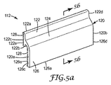
図5a及び5bに示されるように、取付け物品112は、第1の末端部120aと、第2の末端部120bと、第1の末端部120aから第2の末端部120bまでそれぞれ延在する、第1の部分122と、接続部分124と、第2の部分126と、を有する細長い本体120を含む。
As shown in FIGS. 5a and 5b, the
第1の部分122は、図1〜3に示される第1の部分22と類似しており、第1の縁部122aと、第2の縁部122bと、第1の末端部122cと、第2の末端部122dと、第1の縁部122aと第2の縁部122bとの間で第1の末端部122cから第2の末端部122dまで延在する第1の取付け面122eと、を含む。
The
図5bを参照すると、第1の部分122は、第1の縁部122aに隣接した任意のトゥ部分122fと、接続部分124と連続してトゥ部分122fから延在する中央領域122gと、中央領域122gから第2の縁部122bまで延在するヒール部分122hと、を含む。接続部分124は、第1の取付け面122eとは概ね反対側で第1の部分122から外向きに延在し、第2の部分126は、第1の部分122とは反対側で接続部分124の末端部と接合される。
Referring to FIG. 5b, the
図示される実施形態では、トゥ部分122fは、第1の部分122の第1の縁部122aから接続部分124まで延在する、第1の取付け面122eとは反対側の裏面122f’を含む。ヒール部分122hは、接続部分124から第1の部分122の第2の縁部122bまで延在する、第1の取付け面122eとは反対側の裏面122h’を含む。このようにして、接続部分124は、第1の縁部122aと第2の縁部122bとの中間の領域で、又はトゥ部分の裏面122f’とヒール部分の裏面122h’との間で第1の部分122に接している。即ち、接続部分124は、第1の部分122の中央領域122gに接しており、中央領域122gから反対方向で外向きに延在するトゥ部分122f及びヒール部分122hは、中央領域122gに接していない。別の実施形態では、トゥ部分122fが省略され、それによって第1の部分122がヒール部分122fのみを含んでもよい。
In the illustrated embodiment, the
取付け物品112に、トゥ部分122fと、中央領域122gと、ヒール部分122hとを備えた第1の部分122を設けることによって、取付け物品112は、グレージング106に対する衝撃力により良好に耐えることができ、またそれによって、グレージング106/窓用フィルム108ユニットが窓枠104に対してよりしっかりと取り付けられることが見出されている。
By providing the mounting
図5aに示されるように、第2の部分126は、接続部分124から、第1の部分122からずれた位置まで延在し、第1の縁部126aと、第1の末端部126cと、第2の末端部126dと、第1の縁部126aと接続部分124との間で第1の末端部126cから第2の末端部126dまで延在する第2の取付け面126eと、を含む。
As shown in FIG. 5a, the
第1の取付け面122e及び第2の取付け面126eは、図1〜3を参照して上述したものと類似のものであってもよい接着面128を備える。図4及び5に示される実施形態では、接着面128は同じ方向に向き、ずれた概ね平行な面内に位置する。この構成は、窓枠104の幅が狭く、窓枠104の側面がグレージング106に概ね平行な取付け面となり、それによって、窓用フィルム108が、図2に示されるように窓枠のレッジに固定するよりも、窓枠104の側面により簡単に固定される、図4に示される構成などの用途に有用である。
The
この構成は、住居用の窓構造物において一般的である。この構成では、取付け物品112の第1の部分122は窓用フィルム108に固着され、取付け物品112の第2の部分126は窓枠104の側面に固着される。そのような構成は、(剥離の形ではなく)剪断又は張力の形で窓に対する衝撃によって発生する力に耐えることができ、それによって、窓組立体の耐衝撃性を増加させる、また、目立たない薄いプロファイルを有し、したがってより美観上魅力的な、住居用窓組立体のための取付けメカニズムを提供する。
This configuration is common in residential window structures. In this configuration, the
取付け物品112と窓枠104及び窓用フィルム108のそれぞれの表面との間の固着を更に向上させ、それによって窓組立体102の耐衝撃性を更に向上させるため、取付け物品112と窓用フィルム108との間の間隙130は、図2を参照して上述したようなシーラントで所望により充填されてもよい。
In order to further improve the adhesion between the mounting
当業者であれば、本発明の概念から逸脱することなく、上述した本発明を様々に変更及び修正できることを理解されよう。例えば、取付け物品は、本明細書にて上述したものとは異なる窓組立体の角度に一致する取付け面を有するように修正されてもよい。それに加えて、窓組立体の角部における取付け物品の設置を容易にするため、取付け物品は、例えば、90°の角用の個片の形態で製作されてもよい。このように、本発明の範囲は、本出願に記載の構造に限定すべきではなく、特許請求の範囲の文言によって説明される構造物及びそれらの同等物によってのみ限定されるものである。 Those skilled in the art will appreciate that various changes and modifications can be made to the invention described above without departing from the inventive concept. For example, the mounting article may be modified to have a mounting surface that matches a different angle of the window assembly than that described hereinabove. In addition, to facilitate installation of the mounting article at the corners of the window assembly, the mounting article may be fabricated, for example, in the form of 90 ° corner pieces. Thus, the scope of the present invention should not be limited to the structures described in this application, but only by the structures described by the language of the claims and their equivalents.
Claims (4)
第2の取付け面を含む第2の部分と、
前記第1の部分と前記第2の部分との間に配置された接続部分とを有する本体を具備する窓用フィルムを窓枠に固定するための取付け物品であって、
前記第1の部分が、前記第2の部分に向かって延在するとともに、前記第2の部分及び前記接続部分に対して間隔を空けて配置されたヒール部分を有し、更に、前記ヒール部分が、前記第1の取付け面の少なくとも一部分を有する物品。 A first portion including a first mounting surface;
A second portion including a second mounting surface;
A mounting article for fixing a window film to a window frame comprising a main body having a connection portion disposed between the first portion and the second portion,
The first portion includes a heel portion extending toward the second portion and spaced from the second portion and the connecting portion, and further comprising the heel portion. An article having at least a portion of the first attachment surface.
(b)該窓枠内に配置された、相対する主表面を有するグレージングと、
(c)前記グレージングの相対する主表面の少なくとも一つの上に配置された窓用フィルムと、
(d)前記窓用フィルムの周辺の少なくとも一部分を前記窓枠に固定するための物品であって、第1の末端部及び第2の末端部と、前記窓枠及び前記窓用フィルムの少なくとも一方に接着剤で固着される第1の取付け面を有する第1の部分と、前記第1の取付け面とは反対側で前記第1の部分から外向きに延在する接続部分と、前記第1の部分とは反対側で前記接続部分の末端部と接合され且つ前記窓枠及び前記窓用フィルムの他方に接着剤で固着される第2の取付け面を有する第2の部分と、を備えた細長い本体を有する物品と、
を具備する耐衝撃性窓組立体。 (A) a window frame;
(B) a glazing having an opposing main surface disposed within the window frame;
(C) a window film disposed on at least one of the opposing major surfaces of the glazing;
(D) An article for fixing at least a part of the periphery of the window film to the window frame, the first end portion and the second end portion, and at least one of the window frame and the window film. A first portion having a first mounting surface secured to the first mounting surface with an adhesive; a connection portion extending outwardly from the first portion on the opposite side of the first mounting surface; and the first portion A second portion having a second mounting surface that is bonded to the other end of the connecting portion on the opposite side of the connecting portion and is fixed to the other of the window frame and the window film with an adhesive. An article having an elongated body;
An impact resistant window assembly.
Applications Claiming Priority (3)
| Application Number | Priority Date | Filing Date | Title |
|---|---|---|---|
| US11/959,072 | 2007-12-18 | ||
| US11/959,072 US9222299B2 (en) | 2007-12-18 | 2007-12-18 | Window film attachment article |
| PCT/US2008/085795 WO2009082611A1 (en) | 2007-12-18 | 2008-12-08 | Window film attachment article |
Publications (3)
| Publication Number | Publication Date |
|---|---|
| JP2011506807A JP2011506807A (en) | 2011-03-03 |
| JP2011506807A5 JP2011506807A5 (en) | 2012-01-26 |
| JP5336512B2 true JP5336512B2 (en) | 2013-11-06 |
Family
ID=40751407
Family Applications (1)
| Application Number | Title | Priority Date | Filing Date |
|---|---|---|---|
| JP2010539611A Active JP5336512B2 (en) | 2007-12-18 | 2008-12-08 | Window film attachment |
Country Status (6)
| Country | Link |
|---|---|
| US (1) | US9222299B2 (en) |
| EP (1) | EP2231982A4 (en) |
| JP (1) | JP5336512B2 (en) |
| CN (2) | CN101903610A (en) |
| TW (1) | TWI557307B (en) |
| WO (1) | WO2009082611A1 (en) |
Families Citing this family (17)
| Publication number | Priority date | Publication date | Assignee | Title |
|---|---|---|---|---|
| US7958682B2 (en) * | 2009-02-11 | 2011-06-14 | Innovative Security Concepts | Window film anchoring device |
| CA2674768A1 (en) * | 2009-08-03 | 2011-02-03 | Prelco Inc. | Rigid glazing system using extrusion adherence |
| WO2011062946A1 (en) * | 2009-11-17 | 2011-05-26 | Madico, Inc. | Blast mitigation safety glass system |
| SG10201504964YA (en) * | 2010-03-23 | 2015-07-30 | Clear Wall Corp | Energy-efficient fenestration assemblies |
| FR2983264B1 (en) * | 2011-11-29 | 2016-04-01 | Mecano I D | ASSEMBLY PIECE |
| US20150159422A1 (en) * | 2011-12-09 | 2015-06-11 | 3M Innovative Properties Company | Window frame wrapping system |
| DE102012103757B3 (en) * | 2012-04-27 | 2013-05-23 | Webasto Ag | Arrangement for closing opening of vehicle, has disk and splinter shield film that is attached to disk, where disk and splinter shield film are provided with foam casing in boundary area of disk |
| CN202954459U (en) * | 2012-11-23 | 2013-05-29 | 3M中国有限公司 | Hidden-frame glass curtain wall connection part matched with safe film to be used |
| USD735009S1 (en) | 2013-07-08 | 2015-07-28 | 3M Innovative Properties Company | Cutting plate for a window film attachment applicator tool |
| USD735010S1 (en) | 2013-07-08 | 2015-07-28 | 3M Innovative Properties Company | Window film attachment applicator tool |
| USD762438S1 (en) | 2013-07-08 | 2016-08-02 | 3M Innovative Properties Company | Window film attachment applicator tool |
| US20150040492A1 (en) * | 2013-10-25 | 2015-02-12 | Thomas Rafter | Window Reinforcing Assembly |
| US10480243B2 (en) * | 2013-10-25 | 2019-11-19 | Rcrew, Inc. | Two piece window edge corner system and method for installation |
| SG11201608997XA (en) * | 2014-04-28 | 2016-12-29 | Jan Franck | Fixed glazing |
| US9938763B2 (en) | 2015-11-05 | 2018-04-10 | Tim Miller | System and method for a security film |
| US11008800B2 (en) * | 2018-05-29 | 2021-05-18 | Alpen High Performance Products, Inc. | Secondary window |
| GB2597899A (en) * | 2020-06-10 | 2022-02-16 | Pfs Holdings Ltd | Anchoring apparatus |
Family Cites Families (42)
| Publication number | Priority date | Publication date | Assignee | Title |
|---|---|---|---|---|
| US2541768A (en) * | 1948-07-03 | 1951-02-13 | Kenneth M Keller | Flexible molding strip |
| JPS4861626U (en) * | 1971-11-11 | 1973-08-06 | ||
| US4075803A (en) | 1976-06-24 | 1978-02-28 | Formex Manufacturing, Inc. | Split duct terminator |
| JPS5450042A (en) | 1977-09-27 | 1979-04-19 | Sumitomo Chem Co Ltd | Coated article and its production |
| US4184297A (en) | 1978-06-05 | 1980-01-22 | Plaskolite, Inc. | Extruded plastic panel holding and jointing strips and window assemblies therewith |
| FR2428729A1 (en) | 1978-06-13 | 1980-01-11 | Luther Rodney | FLEXIBLE STRIP FOR GLAZING |
| JPS55121885U (en) * | 1979-02-21 | 1980-08-29 | ||
| JPS5829785U (en) * | 1981-08-24 | 1983-02-26 | 株式会社川口技研 | Insulation device for windows and glass doors |
| US4561223A (en) * | 1983-02-03 | 1985-12-31 | Defender Energy Of Connecticut, Inc. | Panel fastener system and retaining member |
| US4540623A (en) | 1983-10-14 | 1985-09-10 | The Dow Chemical Company | Coextruded multi-layered articles |
| GB2163803B (en) * | 1984-08-31 | 1988-02-24 | Sterwin Ag | Glazing system |
| GB2184475A (en) | 1985-12-16 | 1987-06-24 | Robert Mcdonald Richie | Glazing window frames |
| JPH03108712U (en) * | 1990-02-26 | 1991-11-08 | ||
| DE9003486U1 (en) * | 1990-03-24 | 1990-05-31 | Alfred Schellenberg Gmbh, 5900 Siegen, De | |
| JPH0733745B2 (en) * | 1991-05-09 | 1995-04-12 | 株式会社ニフコ | Structure for attaching decorative members to window frames |
| JPH0587140A (en) | 1991-05-27 | 1993-04-06 | Ebara Corp | Magnetic bearing device |
| JPH0587140U (en) * | 1991-05-28 | 1993-11-22 | 多摩防水技研有限会社 | Temporary fixing material such as glass |
| US6040061A (en) | 1992-10-01 | 2000-03-21 | 3M Innovative Properties Company | Tear resistant multilayer films based on sebacic acid copolyesters and articles incorporating such films |
| CA2106262C (en) | 1992-10-01 | 2003-11-18 | Ralph H. Bland | Tear resistant multilayer films and articles incorporating such films |
| JP2963387B2 (en) * | 1993-07-07 | 1999-10-18 | 旭硝子株式会社 | Double glazing with attachment |
| US5426897A (en) | 1994-01-03 | 1995-06-27 | Gazaway; Vaden S. | Glass restraint system and windows |
| JP3069276B2 (en) * | 1995-08-28 | 2000-07-24 | ワイケイケイアーキテクチュラルプロダクツ株式会社 | Bead for double glazing and double glazing body incorporating the same |
| US5937611A (en) | 1995-09-28 | 1999-08-17 | Howes; Stephen E. | Method of making an impact resistant window |
| US6101783A (en) | 1995-09-28 | 2000-08-15 | Howes; Stephen E. | Impact resistant window |
| US5778629A (en) | 1995-09-28 | 1998-07-14 | Howes; Stephen E. | Impact resistant window |
| US6108999A (en) | 1997-02-10 | 2000-08-29 | General Electric Co. | Window and glazing for a window |
| USD393083S (en) * | 1997-05-17 | 1998-03-31 | M & G Manufacturing Co. Inc. | Window pour mold |
| CA2205669C (en) | 1997-06-19 | 2000-05-16 | Paul W. Poirier | Method and apparatus for edge mounting security window film in a window frame |
| PT1000218E (en) * | 1997-07-30 | 2006-07-31 | Framegard Anchoring Systems Lt | EQUIPMENT AND METHOD FOR PROTECTING A PANEL AGAINST IMPACT |
| US6082062A (en) | 1997-08-28 | 2000-07-04 | Alflen; Michael J. | Security attachment system |
| US6912817B1 (en) * | 1998-12-10 | 2005-07-05 | Steven R. Sabac | Restraint channel system for retaining impact panel |
| JP2001152635A (en) * | 1999-11-26 | 2001-06-05 | Etsuo Kanazawa | Recessed corner member for stairs |
| US7775003B2 (en) * | 1999-12-08 | 2010-08-17 | Sabac Steven R | Apparatus for securing an impact resistant window to a window frame |
| JP2002138763A (en) * | 2000-10-27 | 2002-05-17 | Asahi Glass Co Ltd | Attachment and bead for double glazing |
| GB2374893B (en) | 2001-04-25 | 2004-08-04 | Framegard Anchoring Systems Lt | An anchoring profile, a frame assembly and a method for securing a pane against impact |
| US6832457B2 (en) * | 2001-09-27 | 2004-12-21 | Hehr International, Inc. | Window assembly |
| US6715245B2 (en) * | 2002-04-03 | 2004-04-06 | Signature Door Co., Inc. | Impact resistant pane and mounting |
| US7204901B2 (en) | 2003-02-03 | 2007-04-17 | Zicron Corporation | Low cost process for manufacture of hurricane resistant, glass, impact resistant units |
| CN1867749B (en) * | 2003-06-23 | 2011-10-05 | Ppg工业俄亥俄公司 | Integrated window sash and methods of making an integrated window sash |
| JP2005207226A (en) | 2005-01-26 | 2005-08-04 | Nippon Sheet Glass Co Ltd | Assembling structure of fireproof glass, fireproof glass door, and fireproof glass window |
| EP1724429A1 (en) * | 2005-05-13 | 2006-11-22 | Matthias Stoll | Cover for windows and doors |
| CN200989131Y (en) * | 2006-12-15 | 2007-12-12 | 郑州引航实业有限公司 | Single-piece glass combined vehicle window |
-
2007
- 2007-12-18 US US11/959,072 patent/US9222299B2/en active Active
-
2008
- 2008-12-08 EP EP08865437.1A patent/EP2231982A4/en not_active Withdrawn
- 2008-12-08 CN CN2008801214566A patent/CN101903610A/en active Pending
- 2008-12-08 WO PCT/US2008/085795 patent/WO2009082611A1/en active Application Filing
- 2008-12-08 JP JP2010539611A patent/JP5336512B2/en active Active
- 2008-12-08 CN CN201510434351.8A patent/CN105386691B/en not_active Expired - Fee Related
- 2008-12-17 TW TW097149182A patent/TWI557307B/en not_active IP Right Cessation
Also Published As
| Publication number | Publication date |
|---|---|
| TW200946763A (en) | 2009-11-16 |
| CN105386691A (en) | 2016-03-09 |
| EP2231982A4 (en) | 2015-09-09 |
| WO2009082611A1 (en) | 2009-07-02 |
| US9222299B2 (en) | 2015-12-29 |
| TWI557307B (en) | 2016-11-11 |
| US20090151255A1 (en) | 2009-06-18 |
| CN105386691B (en) | 2018-04-06 |
| CN101903610A (en) | 2010-12-01 |
| JP2011506807A (en) | 2011-03-03 |
| EP2231982A1 (en) | 2010-09-29 |
Similar Documents
| Publication | Publication Date | Title |
|---|---|---|
| JP5336512B2 (en) | Window film attachment | |
| US11174667B2 (en) | Laminated glass retention system | |
| US8272178B2 (en) | Press-fit storm window | |
| EP0014141B1 (en) | Laminated glass with a high impact resistance | |
| CA2205669C (en) | Method and apparatus for edge mounting security window film in a window frame | |
| US20070193140A1 (en) | Impact resistant door light | |
| US20100107497A1 (en) | Full view storm door | |
| US7775003B2 (en) | Apparatus for securing an impact resistant window to a window frame | |
| CA2443205A1 (en) | An anchoring profile, a frame assembly and a method for securing a pane against impact | |
| US20160145934A1 (en) | Protective Additional Glazing Systems, Apparatus, and Methods For Structural Openings | |
| WO2006052385A2 (en) | Maintenance free jamb | |
| US20180038156A1 (en) | Protective glazing systems, apparatus and methods for structural openings | |
| EP3344839B1 (en) | Superinsulating window unit | |
| EP2584135A2 (en) | Insulated glass unit | |
| CN111743354A (en) | Door for a refrigeration cabinet | |
| US10837223B2 (en) | System and method for a security film | |
| US20080104904A1 (en) | Window | |
| WO2010032747A1 (en) | Heat-insulation layer installation method and heat-insulation layer installation structure | |
| ATE317488T1 (en) | GLASS BEAD FASTENING | |
| EP1589179A3 (en) | Frame section member to be fixed on a support and corresponding door or window | |
| KR20090008915U (en) | The draft interception pannel for openung and shutting wood door |
Legal Events
| Date | Code | Title | Description |
|---|---|---|---|
| A521 | Request for written amendment filed |
Free format text: JAPANESE INTERMEDIATE CODE: A523 Effective date: 20111129 |
|
| A621 | Written request for application examination |
Free format text: JAPANESE INTERMEDIATE CODE: A621 Effective date: 20111129 |
|
| A977 | Report on retrieval |
Free format text: JAPANESE INTERMEDIATE CODE: A971007 Effective date: 20130430 |
|
| TRDD | Decision of grant or rejection written | ||
| A01 | Written decision to grant a patent or to grant a registration (utility model) |
Free format text: JAPANESE INTERMEDIATE CODE: A01 Effective date: 20130702 |
|
| A61 | First payment of annual fees (during grant procedure) |
Free format text: JAPANESE INTERMEDIATE CODE: A61 Effective date: 20130801 |
|
| R150 | Certificate of patent or registration of utility model |
Ref document number: 5336512 Country of ref document: JP Free format text: JAPANESE INTERMEDIATE CODE: R150 Free format text: JAPANESE INTERMEDIATE CODE: R150 |
|
| R250 | Receipt of annual fees |
Free format text: JAPANESE INTERMEDIATE CODE: R250 |
|
| R250 | Receipt of annual fees |
Free format text: JAPANESE INTERMEDIATE CODE: R250 |
|
| R250 | Receipt of annual fees |
Free format text: JAPANESE INTERMEDIATE CODE: R250 |
|
| R250 | Receipt of annual fees |
Free format text: JAPANESE INTERMEDIATE CODE: R250 |
|
| R250 | Receipt of annual fees |
Free format text: JAPANESE INTERMEDIATE CODE: R250 |
|
| R250 | Receipt of annual fees |
Free format text: JAPANESE INTERMEDIATE CODE: R250 |
|
| R250 | Receipt of annual fees |
Free format text: JAPANESE INTERMEDIATE CODE: R250 |