JP5335111B2 - Carbonated water discharge unit, carbonated water discharge device - Google Patents
Carbonated water discharge unit, carbonated water discharge device Download PDFInfo
- Publication number
- JP5335111B2 JP5335111B2 JP2012056480A JP2012056480A JP5335111B2 JP 5335111 B2 JP5335111 B2 JP 5335111B2 JP 2012056480 A JP2012056480 A JP 2012056480A JP 2012056480 A JP2012056480 A JP 2012056480A JP 5335111 B2 JP5335111 B2 JP 5335111B2
- Authority
- JP
- Japan
- Prior art keywords
- carbon dioxide
- water
- water supply
- dioxide gas
- gas
- Prior art date
- Legal status (The legal status is an assumption and is not a legal conclusion. Google has not performed a legal analysis and makes no representation as to the accuracy of the status listed.)
- Active
Links
- XLYOFNOQVPJJNP-UHFFFAOYSA-N water Substances O XLYOFNOQVPJJNP-UHFFFAOYSA-N 0.000 title claims description 260
- CURLTUGMZLYLDI-UHFFFAOYSA-N Carbon dioxide Chemical compound O=C=O CURLTUGMZLYLDI-UHFFFAOYSA-N 0.000 claims description 300
- 229910002092 carbon dioxide Inorganic materials 0.000 claims description 150
- 239000001569 carbon dioxide Substances 0.000 claims description 150
- 238000003756 stirring Methods 0.000 claims description 32
- 230000002093 peripheral effect Effects 0.000 claims description 13
- BVKZGUZCCUSVTD-UHFFFAOYSA-L Carbonate Chemical compound [O-]C([O-])=O BVKZGUZCCUSVTD-UHFFFAOYSA-L 0.000 description 8
- 238000004090 dissolution Methods 0.000 description 7
- 238000010586 diagram Methods 0.000 description 5
- 230000000694 effects Effects 0.000 description 4
- 238000013019 agitation Methods 0.000 description 3
- 230000003796 beauty Effects 0.000 description 3
- 238000000034 method Methods 0.000 description 3
- 230000017531 blood circulation Effects 0.000 description 2
- BVKZGUZCCUSVTD-UHFFFAOYSA-N carbonic acid Chemical compound OC(O)=O BVKZGUZCCUSVTD-UHFFFAOYSA-N 0.000 description 2
- 210000004761 scalp Anatomy 0.000 description 2
- OKTJSMMVPCPJKN-UHFFFAOYSA-N Carbon Chemical compound [C] OKTJSMMVPCPJKN-UHFFFAOYSA-N 0.000 description 1
- 230000002378 acidificating effect Effects 0.000 description 1
- 230000004888 barrier function Effects 0.000 description 1
- 229910052799 carbon Inorganic materials 0.000 description 1
- 238000011978 dissolution method Methods 0.000 description 1
- 238000005187 foaming Methods 0.000 description 1
- 230000008014 freezing Effects 0.000 description 1
- 238000007710 freezing Methods 0.000 description 1
- 230000003779 hair growth Effects 0.000 description 1
- 210000003128 head Anatomy 0.000 description 1
- 230000002452 interceptive effect Effects 0.000 description 1
- 239000007788 liquid Substances 0.000 description 1
- 238000004519 manufacturing process Methods 0.000 description 1
- 239000000463 material Substances 0.000 description 1
- 239000002184 metal Substances 0.000 description 1
- 239000011148 porous material Substances 0.000 description 1
- 230000001737 promoting effect Effects 0.000 description 1
- 239000002453 shampoo Substances 0.000 description 1
- 230000005514 two-phase flow Effects 0.000 description 1
- 238000005406 washing Methods 0.000 description 1
Images

Landscapes
- Domestic Plumbing Installations (AREA)
- Bathtubs, Showers, And Their Attachments (AREA)
- Devices For Medical Bathing And Washing (AREA)
- Accessories For Mixers (AREA)
Description
本発明は、給水に炭酸ガスを混合して炭酸水を生成し、該炭酸水を放出する炭酸水放出ユニットと、それを備えた炭酸水放出装置に関する。 The present invention relates to a carbonated water discharge unit that mixes carbon dioxide gas with feed water to generate carbonated water and discharges the carbonated water, and a carbonated water discharge apparatus including the carbonated water discharge unit.
美容室や理容室などで使用するシャンプー剤やパーマ液などによりアルカリ性になった髪を、健康な状態である弱酸性に戻すため、炭酸水による洗髪が有効であることが知られている。また、炭酸水に含まれる炭酸(CO2)の発泡により、頭皮の毛穴に詰まった脂肪などが除去され、頭皮の血行が促進され、髪の育毛効果も期待できることも知られている。さらに、身体の血行促進や保温効果などに、炭酸泉浴が有効であることも知られている。 It is known that washing with carbonated water is effective for returning hair that has been made alkaline by a shampoo or a permanent solution used in a beauty salon or barbershop to a weakly acidic state that is healthy. In addition, it is also known that by the foaming of carbonic acid (CO 2 ) contained in carbonated water, fat clogged in the scalp pores are removed, blood circulation of the scalp is promoted, and hair growth effect can be expected. Furthermore, it is also known that carbonated springs are effective for promoting blood circulation and keeping the body warm.
そこで、たとえば、特許文献1〜3に開示されているような、給水(湯水)に炭酸ガスを混合して炭酸水を生成し、該炭酸水を放出する炭酸水放出装置が種々開発されている。
Thus, for example, various carbonated water discharge devices that generate carbonated water by mixing carbon dioxide with feed water (hot water) and discharge the carbonated water as disclosed in
特許文献1では、ホースの基端を混合栓に導結し、ホースの先端にシャワーヘッドを取り付け、ホース内に細管を挿入している。細管の基端には、炭酸ガス供給装置から炭酸ガスが供給され、細管の先端には、操作弁を介してノズルが取り付けられている。ホース内に給水し、細管内に炭酸ガスを供給して、操作弁を開く。これにより、炭酸ガスがノズルからホース内の給水中に噴出して、給水と炭酸ガスとが混合した炭酸水となり、シャワーヘッドの放水口から放出される。
In
特許文献2では、シャワーヘッドとホースの間に混合器を取り付けている。混合器は、給水を一方向に流す直管状の本管部と、一端が本管部の側部に接続された分岐管部とを備えている。分岐管部の他端には、開閉弁やカールホースなどを介して、ボンベから炭酸ガスが供給される。ホース内に給水し、カールホース内に炭酸ガスを供給して、開閉弁を開く。これにより、炭酸ガスが混合器の分岐管部から本管部内の給水中に混入されて、給水と炭酸ガスとが混合した炭酸水となり、シャワーヘッドの放水口から放出される。
In
特許文献3では、湯水供給路の基端を混合栓に接続し、湯水供給路の先端にシャワーヘッドを取り付けている。また、湯水供給路の中途部に、第1および第2の炭酸ガス溶解器を設けている。第1の炭酸ガス溶解器は、中空の容器から成り、炭酸ガス導入口と水導入口と炭酸泉排出口とを備えている。炭酸ガス導入口には、炭酸ガスボンベから炭酸ガスが供給される。第2の炭酸ガス溶解器は、内側に撹拌用障壁を有する中空円筒から成る第1の炭酸ガス溶解部と、管材をコイル状に巻回した外側流路および内側流路から成る第2の炭酸ガス溶解部とを備えている。
In
第1の炭酸ガス溶解器の水導入口に湯水を供給し、炭酸ガス導入口に炭酸ガスを供給して、炭酸ガスを溶解させた湯水を炭酸泉排出口から排出させる。そして、その湯水を第2の炭酸ガス溶解器の第1および第2の炭酸ガス溶解部を通して、さらに炭酸ガスを湯水に溶解させた後、湯水供給路を介してシャワーヘッドの放水口から放出させる。 Hot water is supplied to the water inlet of the first carbon dioxide dissolver, carbon dioxide is supplied to the carbon dioxide inlet, and hot water in which the carbon dioxide is dissolved is discharged from the carbonated spring outlet. Then, the hot and cold water is further passed through the first and second carbon dioxide gas dissolving portions of the second carbon dioxide gas dissolver, and further carbon dioxide gas is dissolved in the hot water and then discharged from the water outlet of the shower head through the hot water supply path. .
ところで、炭酸ガスには、5℃ぐらいの冷水に最も溶解し易く、水温が上がるに連れて溶解し難くなるという性質がある。このため、特許文献1および特許文献2のように、給水中に炭酸ガスを混入させるだけでは、給水に炭酸ガスが溶解し難い。特に、給水がお湯である場合には、お湯と炭酸ガスとが分離して、シャワーヘッドからお湯が脈動状態で放出されてしまい、シャワーヘッドやホースが振れることもある。
By the way, carbon dioxide gas has the property that it is most easily dissolved in cold water at about 5 ° C. and becomes difficult to dissolve as the water temperature rises. For this reason, as in
また、炭酸ガスには、湯水に溶けても、揮発し易いという性質がある。このため、特許文献3のように、炭酸ガス溶解器からシャワーヘッドまでの水路(ホースなど)が長いと、湯水に溶解した炭酸ガスが、シャワーヘッドへ至るまでに揮発して、シャワーヘッドから炭酸ガスを殆ど含まない湯水が放出されてしまう。
In addition, carbon dioxide gas has the property of being easily volatilized even when dissolved in hot water. For this reason, as in
さらに、シャワーヘッドから放出された湯水の炭酸溶解濃度が低くて、該湯水の酸性度がph6以上になった場合、前述した炭酸の効能や効果が期待できなくなる。 Further, when the carbonate concentration of the hot water discharged from the shower head is low and the hot water has an acidity of ph6 or more, the above-mentioned effects and effects of carbonic acid cannot be expected.
本発明の課題は、炭酸溶解濃度の高い炭酸水を放出することができる炭酸水放出ユニットおよび炭酸水放出装置を提供することである。 The subject of this invention is providing the carbonated water discharge | release unit and carbonated water discharge | release apparatus which can discharge | release carbonated water with high carbonate melt | dissolution density | concentration.
本発明に係る炭酸水放出ユニットは、基端から給水される給水管と、給水管内に挿入され、基端から炭酸ガスが供給されるガス管と、給水管の先端に設けられた放水口と、給水管内のガス管の先端に設けられ、放水口の近傍に位置するノズルとを備え、ガス管内に供給された炭酸ガスをノズルから給水管内の給水中に噴出することにより、該給水に炭酸ガスを混合して炭酸水を生成し、該炭酸水を放水口から放出する炭酸水放出ユニットであって、ノズルは、給水管内の水流方向に対して前方側および後方側が先細り形状であり、中間部にガス管の外径より大きい大径部が設けられ、大径部の外周面が給水管の内周面と平行であって給水の流路を部分的に狭くするように内周面と対向している、アスピレータノズルからなり、大径部の外周面に、炭酸ガスを給水管内の水流方向に対して側方へ噴出する複数の噴出口が異方向を向いて設けられている。また、ノズルと放水口の間に、給水管内の給水と炭酸ガスとを撹拌する撹拌手段が設けられる。撹拌手段は、給水と炭酸ガスとを旋回させて撹拌する第1の撹拌手段と、第1の撹拌手段で攪拌された給水と炭酸ガスを旋回させて撹拌しつつ、給水中の炭酸ガスを微細気泡化する第2の撹拌手段とから構成される。 A carbonated water discharge unit according to the present invention includes a water supply pipe supplied from the base end, a gas pipe inserted into the water supply pipe and supplied with carbon dioxide gas from the base end, and a water outlet provided at the tip of the water supply pipe. A nozzle provided at the tip of the gas pipe in the water supply pipe and located in the vicinity of the water outlet, and carbon dioxide gas supplied into the gas pipe is ejected from the nozzle into the water supply in the water supply pipe. A carbonated water discharge unit that generates carbonated water by mixing gas and discharges the carbonated water from a water discharge port. The nozzle has a tapered shape on the front side and the rear side with respect to the water flow direction in the water supply pipe. A large diameter portion larger than the outer diameter of the gas pipe is provided in the portion, and the outer peripheral surface of the large diameter portion is parallel to the inner peripheral surface of the water supply pipe, and the inner peripheral surface is partially narrowed. Consists of aspirator nozzles facing each other, outer peripheral surface of large diameter part , A plurality of ejection ports for ejecting laterally the carbon dioxide with respect to the water flow direction of the water supply pipe is provided facing different directions. Moreover, the stirring means which stirs the water supply and carbon dioxide gas in a water supply pipe is provided between a nozzle and a water discharge port. The stirring means is a first stirring means that swirls and stirs the water supply and the carbon dioxide gas, and the water supply gas and the carbon dioxide gas stirred by the first stirring means are swirled and stirred while the carbon dioxide gas in the feed water is finely mixed. And a second agitation means for forming bubbles.
上記によると、放水口の近傍までガス管により炭酸ガスを供給し、ガス管の先端に設けたノズルの複数の噴出口から炭酸ガスを、給水管内の給水中に噴出させるので、放水直前で炭酸ガスを給水に溶解させることができる。さらに、それでも溶けきらない炭酸ガスを2つの撹拌手段により給水と撹拌させるので、炭酸ガスを給水に確実に溶解させて、炭酸溶解濃度の高い炭酸水を生成することができる。そして、撹拌手段を経た炭酸水を、溶解している炭酸ガスが揮発する前に、近傍の放水口から放出させることができる。よって、給水の温度にかかわらず、炭酸溶解濃度の高い炭酸水を放出することが可能となる。 According to the above, carbon dioxide gas is supplied to the vicinity of the water discharge port by the gas pipe, and carbon dioxide gas is ejected from the plurality of nozzle outlets provided at the tip of the gas pipe into the feed water in the water supply pipe. Gas can be dissolved in feed water. Furthermore, since the carbon dioxide gas that still cannot be dissolved is agitated with the feed water by the two agitation means, the carbonate gas can be surely dissolved in the feed water to produce carbonated water having a high carbonate dissolution concentration. And the carbonated water which passed through the stirring means can be discharged from the nearby outlet before the dissolved carbon dioxide volatilizes. Therefore, it is possible to discharge carbonated water having a high carbonate dissolution concentration regardless of the temperature of the water supply.
さらに、ノズルの大径部の付近で、給水管内の給水の流路が部分的に狭くなるので、給水の流速が上がって、減圧状態になり、炭酸ガスを各噴出口から給水中に勢いよく噴出させることができる。このため、炭酸ガスの気泡が小さくなって、炭酸ガスを給水に溶解させ易くすることができる。また、炭酸ガスを給水管内の水流方向に対して前方に噴出すると、炭酸ガスが給水に溶解せずに撹拌手段へ到達するおそれがある。また、炭酸ガスを給水管内の水流方向に対して後方に噴出すると、給水の流れを妨げて、放水口からの放水圧の低下を招くおそれがある。然るに、炭酸ガスがノズルの各噴出口から水流方向に対して側方の多方向へ噴出されるので、給水の流れを妨げることなく、炭酸ガスを撹拌手段に到達するまでに給水に溶解させて、放水口からの放水圧の低下を防止することができる。 Furthermore , since the flow path of the water supply in the water supply pipe is partially narrowed near the large diameter portion of the nozzle, the flow rate of the water supply is increased, the pressure is reduced, and the carbon dioxide gas is vigorously fed from each outlet into the water supply. Can be ejected. For this reason, the bubble of a carbon dioxide gas becomes small, and it can make it easy to dissolve a carbon dioxide gas in feed water. Moreover, if carbon dioxide gas is jetted forward with respect to the water flow direction in the water supply pipe, the carbon dioxide gas may reach the stirring means without being dissolved in the water supply. Moreover, if carbon dioxide gas is ejected rearward with respect to the water flow direction in the water supply pipe, the flow of the water supply may be hindered, leading to a decrease in the water discharge pressure from the water discharge port. However, since carbon dioxide gas is ejected from each nozzle outlet in multiple directions lateral to the water flow direction, the carbon dioxide gas is dissolved in the water supply before reaching the stirring means without interfering with the flow of the water supply. Moreover, the fall of the water discharge pressure from a water discharge port can be prevented.
本発明では、上記炭酸水放出ユニットにおいて、第1の撹拌手段が、給水と炭酸ガスを螺旋状に攪拌する複数のコイルスプリングから構成されていてもよい。 In the present invention, in the carbonated water discharge unit, the first stirring means may be composed of a plurality of coil springs that spirally stir the water supply and carbon dioxide gas .
これにより、複数のコイルスプリングという簡単で安価な構成で、給水や炭酸ガスの流れを妨げることなく、給水と炭酸ガスを螺旋状に撹拌して、炭酸ガスを効率良く給水に溶解させることができる。 Thus, with a simple and inexpensive configuration of a plurality of coil springs, the water supply and the carbon dioxide gas can be stirred in a spiral manner without disturbing the flow of the water supply and the carbon dioxide gas, and the carbon dioxide gas can be efficiently dissolved in the water supply. .
本発明では、上記炭酸水放出ユニットにおいて、第2の撹拌手段が、旋回流発生部材を内部に有する微細気泡発生器から構成されていてもよい。 In the present invention, in the carbonated water discharge unit, the second stirring means may be constituted by a fine bubble generator having a swirl flow generating member therein .
これにより、給水と炭酸ガスとを旋回させて撹拌しつつ、給水中の炭酸ガスを微細気泡発生器で細かく分割して、微細気泡とし、給水に確実に溶解させることができる。 As a result, while the water supply and the carbon dioxide gas are swirled and stirred , the carbon dioxide gas in the water supply can be finely divided by the fine bubble generator to form fine bubbles, which can be reliably dissolved in the water supply.
次に、本発明に係る炭酸水放出装置は、上述した炭酸水放出ユニットと、炭酸ガスを所定の圧力でガス管内へ供給する炭酸ガス供給装置とを備えている。 Next, a carbonated water discharge device according to the present invention includes the carbonated water discharge unit described above and a carbon dioxide supply device that supplies carbon dioxide into a gas pipe at a predetermined pressure.
本発明では、上記炭酸水放出装置において、炭酸ガス供給装置からガス管内へ供給する炭酸ガスの流量を調整する流量計を設けるのが好ましい。 In the present invention, in the carbonated water discharge device, it is preferable to provide a flow meter for adjusting the flow rate of carbon dioxide supplied from the carbon dioxide supply device into the gas pipe.
これにより、給水圧や給水量に応じて、流量計により炭酸ガスの供給流量を最適に調整して、給水に炭酸ガスを溶解させることができる。 Thereby, according to the feed water pressure or the feed water amount, the supply flow rate of carbon dioxide can be optimally adjusted by the flow meter, and the carbon dioxide can be dissolved in the feed water.
本発明によれば、炭酸溶解濃度の高い炭酸水を放出することができる炭酸水放出ユニットおよび炭酸水放出装置を提供することが可能となる。 ADVANTAGE OF THE INVENTION According to this invention, it becomes possible to provide the carbonated water discharge | release unit and carbonated water discharge | release apparatus which can discharge | release carbonated water with a high carbonate melt | dissolution density | concentration.
以下、本発明の実施形態につき、図面を参照しながら説明する。各図において、同一の部分または対応する部分には、同一符号を付してある。 Hereinafter, embodiments of the present invention will be described with reference to the drawings. In the drawings, the same or corresponding parts are denoted by the same reference numerals.
まず、本発明の一実施形態による炭酸水放出装置100の構成を説明する。
First, the structure of the carbonated
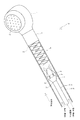
図1は、炭酸水放出装置100の構成図である。炭酸水放出装置100には、炭酸水シャワーユニット10と炭酸ガス供給装置20とが備わっている。炭酸水シャワーユニット(以下、単に「シャワーユニット」という。)10は、たとえばシャワー台30に設けられている。炭酸ガス供給装置20は、たとえばシャワー台30の傍に設置されている。シャワーユニット10は、本発明の「炭酸水放出ユニット」の一例である。
FIG. 1 is a configuration diagram of a carbonated
炭酸ガス供給装置20内には、炭酸ガスボンベ21とヒータ付圧力調整器22が収容されている。炭酸ガスボンベ21は、炭酸ガス(CO2)が充填された、たとえば5kgのボンベである。炭酸ガスボンベ21のガス送出口(図示省略)には、耐圧ホース23の一端が接続されている。耐圧ホース23の他端は、ヒータ付圧力調整器22のガス受入口(図示省略)に接続されている。
In the carbon
ヒータ付圧力調整器22の複数のガス送出口(図示省略)には、それぞれ耐圧ホース24の一端が接続されている。各耐圧ホース24の他端は、それぞれワンタッチカプラ25の一端に接続されている。各ワンタッチカプラ25の他端は、炭酸ガス供給装置20の側部から突出している。各ワンタッチカプラ25の他端には、それぞれホースが着脱自在に接続される。
One end of a
炭酸ガスボンベ21の栓(図示省略)を開くと、炭酸ガスが炭酸ガスボンベ21から耐圧ホース23内を通って、ヒータ付圧力調整器22へ供給される。ヒータ付圧力調整器22は、炭酸ガスの供給圧力を調整し、炭酸ガスを所定の圧力で耐圧ホース24内へ送り込む。また、ヒータ付圧力調整器22は、炭酸ガスを温めて、凍結を防止する。
When the stopper (not shown) of the
図2は、シャワーユニット10の要部構造図である。シャワーユニット10には、シャワーヘッド1、シャワーホース2、ガスホース3、アスピレータノズル4、撹拌スプリング5、および微細気泡発生器6が備わっている。
FIG. 2 is a structural diagram of a main part of the
シャワーヘッド1は、たとえば、美容室や理容室などで使用されるような、手のひらに収まる小型のシャワーヘッドである。シャワーヘッド1は、微細気泡発生器6を介して、シャワーホース2の先端2sに設けられている。シャワーヘッド1のじょうろ状の給水口1aは、シャワーホース2の管軸方向に対して側方を向いている。
The
シャワーホース2は、図1に示すように、複数の大径のホース2a、2b、2cから構成されている。ホース2aの基端2kは、たとえば給湯器のような、給水源40に接続されている。ホース2aの先端とホース2bの基端とは、給水栓31を介して連結されている。ホース2bの先端とホース2cの基端とは、三方接続管32を介して連結されている。
The
給水源40から湯水を供給して、給水栓31を開くことにより、給水がシャワーホース2の各ホース2a、2b、2c内と微細気泡発生器6内とを通って、シャワーヘッド1の放水口1aから放出する。すなわち、シャワーホース2は、基端2kから給水される。シャワーヘッド1は、放水口1aから放水する。シャワーホース2は、本発明の「給水管」の一例である。
By supplying hot water from the
ガスホース3は、図1および図2に示すように、複数の小径のホース3a、3b、3cから構成されている。図1に示すように、ホース3aの基端3kは、ワンタッチカプラ25の他端に接続されている。ホース3aの先端とホース3bの基端とは、流量計7を介して連結されている。図2に示すように、ホース3cは、シャワーホース2のホース2c内に挿入されている。ホース3cの先端3sには、アスピレータノズル4が設けられている。ホース3cの基端とホース3bの先端とは、図1に示すように、逆止弁33と三方接続管32を介して連結されている。
As shown in FIGS. 1 and 2, the
炭酸ガス供給装置20から炭酸ガスを所定の圧力で供給して、流量計7のハンドル7aを開操作する。すると、炭酸ガスが、炭酸ガス供給装置20から、ワンタッチカプラ25、ホース3a、流量計7、ホース3b、逆止弁33、三方接続管32、およびホース3cを通って、アスピレータノズル4の噴出口4cからシャワーホース2のホース2c内に噴出される。すなわち、炭酸ガス供給装置20は、炭酸ガスを所定の圧力でガスホース3内へ供給する。ガスホース3は、基端3kから炭酸ガスが供給される。ガスホース3は、本発明の「ガス管」の一例である。
Carbon dioxide gas is supplied from the carbon
流量計7の目盛を見ながらハンドル7aを操作することで、ガスホース3のホース3b、3cを通して先端3s側へ供給する炭酸ガスの流量を調整できる。
By operating the handle 7a while looking at the scale of the
図1では、シャワーユニット10を1つだけ炭酸ガス供給装置20に接続しているが、各ワンタッチカプラ25を介して複数のシャワーユニット10を炭酸ガス供給装置20に接続することもできる。その場合、炭酸ガス供給装置20から各シャワーユニット10に炭酸ガスを供給することができる。また、シャワーユニット10以外の、たとえば噴霧器や放水器なども、ホースとワンタッチカプラ25を介して炭酸ガス供給装置20に接続して、炭酸ガスを受容することができる。
In FIG. 1, only one
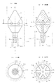
図3は、アスピレータノズル4の構造図である。詳しくは、図3の(a)は、アスピレータノズル4の正面図であり、(b)は、(a)におけるX−X断面図であり、(c)は、(a)におけるY矢視図であり、(d)は、(a)におけるZ−Z断面図である。
FIG. 3 is a structural diagram of the
アスピレータノズル4の接続部4aには、ガスホース3のホース3cの先端3sが圧入により接続される。これにより、アスピレータノズル4は、図2に示すように、シャワーヘッド1の近傍にあるシャワーホース2のホース2c内に位置する。また、アスピレータノズル4の長手方向は、ホース2c、3cの管軸方向と平行になり、アスピレータノズル4の短手方向は、ホース2c、3cの管径方向と平行になる。
The
アスピレータノズル4は、ホース2c内の水流方向(図2)に対して前方側および後方側が先細り形状となっていて、中間部にホース3cの外径より大きい大径部4kを有している。大径部4kの外周面は、ホース2cの内周面と平行であって、給水の流路を部分的に狭くするようにホース2cの内周面と対向している。大径部4kの外周面には、図3に示すように、6つの噴出口4cが、円周方向に等角度間隔で異方向を向いて設けられている。すなわち、各噴出口4cは、ホース2c内の水流方向(図2)に対して側方を向いている。
The
アスピレータノズル4内には、炭酸ガスの流路4bが設けられている。流路4bは、入り口4dからアスピレータノズル4の長手方向へ1本で延びて、アスピレータノズル4の中心付近で6本に分岐し、アスピレータノズル4の短手方向へ放射状に延びて、各噴出口4cに至っている。また、流路4bは、ホース2c、3c内の流路より狭くなっている。各噴出口4cは、連通する流路4bと同等の大きさになっている。
In the
アスピレータノズル4は、炭酸ガス供給装置20からガスホース3内に供給された炭酸ガスを、流路4bを通して噴出口4cから、シャワーホース2内の給水中に多方向に噴出する。アスピレータノズル4は、本発明の「ノズル」の一例である。
The
図2に示すように、アスピレータノズル4とシャワーヘッド1の間には、撹拌用のコイルスプリング5と微細気泡発生器6とが設けられている。コイルスプリング5と微細気泡発生器6は、本発明の「撹拌手段」の一例である。
As shown in FIG. 2, a coil spring 5 for stirring and a
コイルスプリング5は、不規則に絡み合った複数のコイルスプリングから成る。コイルスプリング5は、シャワーホース2のホース2c内に圧入されており、ホース2cの管軸方向へ移動しないようになっている。このコイルスプリング5は、通過する給水と炭酸ガスとを螺旋状に撹拌する。
The coil spring 5 includes a plurality of coil springs that are irregularly intertwined. The coil spring 5 is press-fitted into the
微細気泡発生器6としては、例えば、株式会社田中金属製作所製の商品名「μ−Jet」(登録商標)が用いられる。この微細気泡発生器6は、電源なしで、給水路に設けるだけで、水中の溶存空気を細かく分割して、直径が10μm〜数10μmの微細気泡を発生させる。
As the
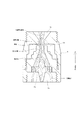
図4は、微細気泡発生器6の断面図である(平成23年9月7日付「管材新聞」第6面記事より引用)。微細気泡発生器6の受入口6bには、シャワーホース2のホース2cの先端2sが接続される。送出口6cには、シャワーヘッド1の受入口が接続される。微細気泡発生器6の内部には、旋回流発生部材6aが設けられている。
FIG. 4 is a cross-sectional view of the fine bubble generator 6 (quoted from the 6th article of “Tube Newspaper” dated September 7, 2011). A
微細気泡発生器6では、給水が受入口6bから旋回流発生部材6aの傾斜面に沿って流れることで、旋回流が発生し、最大流速を得ながら、中心に空気の軸が発生する。そして、負圧空間6dを経由することで、旋回流が局所的に減速し、空気の軸が旋断されて、微細気泡を発生させる(前掲記事より引用)。このため、微細気泡発生器6は、通過する給水と炭酸ガスとを旋回させて撹拌しつつ、炭酸ガスを微細気泡化する。
In the
次に、炭酸水放出装置100による炭酸水生成作用を説明する。
Next, the carbonated water production | generation effect | action by the carbonated
図1の給水源40より所望の温度と量の湯水をシャワーホース2のホース2c内まで給水し、かつ、炭酸ガス供給装置20より炭酸ガスをガスホース3のホース3c内まで供給する。このとき、流量計7により炭酸ガスの供給流量を調整する。
Hot water of a desired temperature and quantity is supplied from the
すると、炭酸ガスが、図2のホース3cの先端3sからアスピレータノズル4の流路4b(図3(b)参照)を通って、複数の噴出口4cから多方向に、ホース2c内を流れる給水中に噴出される。このとき、アスピレータノズル4の大径部4kの付近で、ホース2c内の給水の流路が部分的に狭くなるので、給水の流速が上がって、減圧状態になり、炭酸ガスが各噴出口4cから給水中に勢いよく噴出される。そして、ホース2c内で炭酸ガスと給水とが混合されて、炭酸ガスが給水に溶解して行く。
Then, carbon dioxide gas flows through the
また、アスピレータノズル4の先にあるコイルスプリング5により、炭酸ガスと給水の流れが乱されて、炭酸ガスと給水が螺旋状に撹拌されるので、より多くの炭酸ガスが給水に溶解して行く。
In addition, the flow of the carbon dioxide gas and the water supply is disturbed by the coil spring 5 at the tip of the
さらに、撹拌スプリング5の先にある微細気泡発生器6により、給水中の炭酸ガスが細かく分割されて、微細気泡となり、給水と撹拌されるので、より一層多くの炭酸ガスが給水に溶解して行く。
Further, the
その結果、炭酸ガスが給水に確実に溶解した炭酸溶解濃度の高い炭酸水が生成されて、すぐさま、微細気泡発生器6の先にあるシャワーヘッド1の放水口1aから放出される。
As a result, carbonated water having a high carbon dioxide dissolution concentration in which carbon dioxide gas is reliably dissolved in the feed water is generated and immediately discharged from the water outlet 1a of the
上記実施形態によると、シャワーヘッド1の放水口1aの近傍までガスホース3により炭酸ガスを供給し、ガスホース3の先端に設けたアスピレータノズル4の複数の噴出口4cから炭酸ガスをシャワーホース2内の給水中に噴出させている。このため、放水直前で炭酸ガスを給水に溶解させることができる。
According to the above embodiment, carbon dioxide gas is supplied to the vicinity of the water outlet 1 a of the
さらに、それでも溶けきらない炭酸ガスを、コイルスプリング5と微細気泡発生器6の2つの撹拌手段により給水と撹拌させている。このため、炭酸ガスを給水に確実に溶解させて、炭酸溶解濃度の高い炭酸水を生成することができる。
Further, the carbon dioxide gas that still cannot be dissolved is supplied and stirred by the two stirring means of the coil spring 5 and the
そして、微細気泡発生器6を経た炭酸水を、溶解している炭酸ガスが揮発する前に、近傍にあるシャワーヘッド1の放水口1aから放出させることができる。
And the carbonated water which passed through the
よって、給水の温度にかかわらず、炭酸溶解濃度の高い炭酸水を放出することが可能となる。またこれにより、たとえば温度の高い炭酸水(40℃前後)がシャワーヘッド1から脈動状態で放水されることや、シャワーヘッドやホースが振れることを無くすことができる。
Therefore, it is possible to discharge carbonated water having a high carbonate dissolution concentration regardless of the temperature of the water supply. Thereby, for example, it is possible to prevent the carbonated water having a high temperature (around 40 ° C.) from being discharged from the
また、上記実施形態では、アスピレータノズル4の外周面に、ガスホース3の外径より大きい大径部4kが設けられている。このため、大径部4kの付近でシャワーホース2内の給水の流路が部分的に狭くなり、給水の流速が上がって、減圧状態となり、炭酸ガスを各噴出口4cから給水中に勢いよく噴出させることができる。そして、炭酸ガスの気泡を小さくして、炭酸ガスを給水に溶解させ易くすることができる。
Moreover, in the said embodiment, the
また、炭酸ガスをシャワーホース2内の水流方向に対して前方に噴出すると、炭酸ガスが給水に溶解せずにコイルスプリング5へ到達するおそれがある。また、炭酸ガスをシャワーホース2内の水流方向に対して後方に噴出すると、給水の流れを妨げて、シャワーヘッド1の放水口1aからのシャワー圧の低下を招くおそれがある。
Moreover, if carbon dioxide gas is jetted forward with respect to the water flow direction in the
然るに、上記実施形態では、アスピレータノズル4の大径部4kに複数の噴出口4cを異方向へ向けて設けているので、炭酸ガスが各噴出口4cからシャワーホース2内の水流方向に対して側方の多方向へ噴出される。このため、給水の流れを妨げることなく、炭酸ガスをコイルスプリング5に到達するまでに、給水に溶解させて、シャワーヘッド1の放水口1aからのシャワー圧の低下を防止することができる。
However, in the above-described embodiment, since the plurality of
また、上記実施形態では、アスピレータノズル4の先に、第1の撹拌手段としてコイルスプリング5を設けている。このため、簡単で安価な構成で、給水や炭酸ガスの流れを妨げることなく、給水と炭酸ガスを螺旋状に撹拌して、炭酸ガスを給水に溶解させることができる。
Moreover, in the said embodiment, the coil spring 5 is provided in the front of the
また、上記実施形態では、コイルスプリング5の先に、さらに第2の撹拌手段として微細気泡発生器6を設けている。このため、給水中の炭酸ガスを微細気泡発生器6で細かく分割して、微細気泡とし、給水に確実に溶解させて、万全を期すことができる。
Moreover, in the said embodiment, the
また、上記実施形態では、ガスホース3の中途に流量計7を設けている。このため、給水圧や給水量に応じて、流量計7により炭酸ガスの供給流量を最適に調整して、給水に炭酸ガスを溶解させることができる。
In the above embodiment, the
本発明は、上述した以外にも種々の実施形態を採用することができる。たとえば、上記実施形態では、アスピレータノズル4に6つの噴出口4cを設けた例を示したが、本発明はこれのみに限定するものではない。これ以外に、たとえば、5つ以下または7つ以上の複数の噴出口4cをノズル4に設けるようにしてもよい。また、各噴出口4cの向きは、給水の水流方向に対して垂直な方向や、該垂直方向から所定角度傾いた方向にしてもよい。
The present invention can employ various embodiments other than those described above. For example, in the above-described embodiment, an example in which the six aspirating
また、上記実施形態では、撹拌手段として、コイルスプリング5と微細気泡発生器6を例に示したが、本発明はこれのみに限定するものではない。これ以外に、たとえば、プロペラやナットやねじなどのような螺旋状体、網状体、または渦巻状体などを用いてもよい。また、キャビテーション方式、加圧溶解方式、または気液2相流旋回方式などのような公知の方式により、微細気泡を発生させる微細気泡発生器を用いてもよい。つまり、撹拌手段としては、旋回流を発生させて、給水と炭酸ガスとを撹拌できる手段を用いればよい。ただし、水流に対する抵抗が大きいと、シャワーヘッド1から放水するシャワー圧の低下を招くので、撹拌手段としては水流に対する抵抗の小さいものが好ましい。
Moreover, in the said embodiment, although the coil spring 5 and the
また、上記実施形態では、美容室や理容室などで使用される業務用の小型のシャワーヘッド1から炭酸水を放出させる例を示したが、本発明はこれのみに限定するものではない。これ以外に、たとえば、把持部が長い一般家庭用のシャワーヘッドをシャワーホース2の先端2sに取り付けて、該シャワーヘッドの放水口から炭酸水を放出させるようにしてもよい。この場合、シャワーヘッドの把持部や頭部にノズル4や撹拌手段5、6を内蔵するようにしてもよい。また、炭酸水を放出させる放水口は、シャワーヘッドのじょうろ状の放水口に限らず、蛇口やホースのような筒状の放水口でもよい。
Moreover, in the said embodiment, although the example which discharges carbonated water from the
さらに、上記実施形態では、シャワー台30で炭酸水を放出する炭酸水放出装置100に、本発明を適用した例を挙げたが、シャワー台30を備えない炭酸水放出装置においても、本発明を適用することは可能である。
Furthermore, in the said embodiment, although the example which applied this invention to the carbonated water discharge |
1 シャワーヘッド
1a 放水口
2 シャワーホース
2a、2b、2c ホース
2k 基端
2s 先端
3 ガスホース
3a、3b、3c ホース
3k 基端
3s 先端
4 アスピレータノズル
4c 噴出口
4k 大径部
5 コイルスプリング
6 微細気泡発生器
7 流量計
10 炭酸水シャワーユニット
20 炭酸ガス供給装置
100 炭酸水放出装置
DESCRIPTION OF
4
Claims (5)
前記給水管内に挿入され、炭酸ガス供給装置に接続される基端から炭酸ガスが供給されるガス管と、
前記給水管の先端に設けられた放水口と、
前記給水管内の前記ガス管の先端に設けられ、前記放水口の近傍に位置するノズルと、を備え、
前記ガス管内に供給された炭酸ガスを前記ノズルから前記給水管内の給水中に噴出することにより、該給水に炭酸ガスを混合して炭酸水を生成し、該炭酸水を前記放水口から放出する炭酸水放出ユニットにおいて、
前記ノズルは、前記給水管内の水流方向に対して前方側および後方側が先細り形状であり、中間部に前記ガス管の外径より大きい大径部が設けられ、前記大径部の外周面が前記給水管の内周面と平行であって給水の流路を部分的に狭くするように前記内周面と対向している、アスピレータノズルからなり、前記大径部の外周面に、前記炭酸ガスを前記給水管内の水流方向に対して側方へ噴出する複数の噴出口が異方向を向いて設けられており、
前記ノズルと前記放水口の間に、前記給水管内の前記給水と前記炭酸ガスとを撹拌する撹拌手段を設け、
前記撹拌手段は、給水と炭酸ガスとを旋回させて撹拌する第1の撹拌手段と、前記第1の撹拌手段で攪拌された給水と炭酸ガスを旋回させて撹拌しつつ、給水中の炭酸ガスを微細気泡化する第2の撹拌手段と、から構成される、ことを特徴とする炭酸水放出ユニット。 A water supply pipe supplied from a proximal end connected to a water supply source;
A gas pipe inserted into the water supply pipe and supplied with carbon dioxide gas from a base end connected to a carbon dioxide supply apparatus;
A water outlet provided at the tip of the water supply pipe;
A nozzle provided at the tip of the gas pipe in the water supply pipe and located in the vicinity of the water outlet ,
Carbon dioxide gas supplied into the gas pipe is jetted from the nozzle into the water supply in the water supply pipe, so that carbon dioxide is mixed with the water supply to generate carbonated water, and the carbonated water is discharged from the water outlet. In the carbonated water discharge unit,
The nozzle has a tapered shape on the front side and the rear side with respect to the direction of water flow in the water supply pipe, a large diameter part larger than the outer diameter of the gas pipe is provided in an intermediate part, and an outer peripheral surface of the large diameter part is An aspirator nozzle that is parallel to the inner peripheral surface of the water supply pipe and faces the inner peripheral surface so as to partially narrow the flow path of the water supply, and the carbon dioxide gas on the outer peripheral surface of the large diameter portion A plurality of outlets for jetting sideways with respect to the direction of water flow in the water supply pipe are provided in different directions,
Between the nozzle and the water outlet, there is provided a stirring means for stirring the water supply and the carbon dioxide gas in the water supply pipe,
The agitating means is a first agitating means for agitating the feed water and carbon dioxide gas, and a carbon dioxide gas in the feed water while agitating the agitated feed water and carbon dioxide gas by the first agitating means. A carbonated water discharge unit comprising: a second agitating means for making the gas bubbles into fine bubbles.
前記第1の撹拌手段が、前記給水と前記炭酸ガスを螺旋状に攪拌する複数のコイルスプリングからなる、ことを特徴とする炭酸水放出ユニット。 The carbonated water discharge unit according to claim 1 ,
The carbonated water discharge unit, wherein the first stirring means comprises a plurality of coil springs that spirally stir the water supply and the carbon dioxide gas.
前記第2の撹拌手段が、旋回流発生部材を内部に有する微細気泡発生器からなる、ことを特徴とする炭酸水放出ユニット。 The carbonated water discharge unit according to claim 1 or 2 ,
The carbonated water discharge unit, wherein the second stirring means comprises a fine bubble generator having a swirl flow generating member therein.
前記炭酸ガスを所定の圧力で前記ガス管内へ供給する炭酸ガス供給装置と、
を備えたことを特徴とする炭酸水放出装置。 A carbonated water discharge unit according to any one of claims 1 to 3 ,
A carbon dioxide supply device for supplying the carbon dioxide at a predetermined pressure into the gas pipe;
A carbonated water discharge device characterized by comprising:
前記炭酸ガス供給装置から前記ガス管内へ供給する前記炭酸ガスの流量を調整する流量計を設けた、ことを特徴とする炭酸水放出装置。 The carbonated water discharge device according to claim 4 ,
A carbonated water discharge device comprising a flow meter for adjusting a flow rate of the carbon dioxide gas supplied from the carbon dioxide supply device into the gas pipe.
Priority Applications (1)
| Application Number | Priority Date | Filing Date | Title |
|---|---|---|---|
| JP2012056480A JP5335111B2 (en) | 2012-03-13 | 2012-03-13 | Carbonated water discharge unit, carbonated water discharge device |
Applications Claiming Priority (1)
| Application Number | Priority Date | Filing Date | Title |
|---|---|---|---|
| JP2012056480A JP5335111B2 (en) | 2012-03-13 | 2012-03-13 | Carbonated water discharge unit, carbonated water discharge device |
Publications (2)
| Publication Number | Publication Date |
|---|---|
| JP2013188681A JP2013188681A (en) | 2013-09-26 |
| JP5335111B2 true JP5335111B2 (en) | 2013-11-06 |
Family
ID=49389527
Family Applications (1)
| Application Number | Title | Priority Date | Filing Date |
|---|---|---|---|
| JP2012056480A Active JP5335111B2 (en) | 2012-03-13 | 2012-03-13 | Carbonated water discharge unit, carbonated water discharge device |
Country Status (1)
| Country | Link |
|---|---|
| JP (1) | JP5335111B2 (en) |
Cited By (1)
| Publication number | Priority date | Publication date | Assignee | Title |
|---|---|---|---|---|
| JP2020151390A (en) * | 2019-03-22 | 2020-09-24 | 日東精工株式会社 | shower head |
Families Citing this family (4)
| Publication number | Priority date | Publication date | Assignee | Title |
|---|---|---|---|---|
| JP2014133037A (en) * | 2013-01-11 | 2014-07-24 | Imai:Kk | Carbonate spring production machine |
| WO2016117548A1 (en) * | 2015-01-23 | 2016-07-28 | 聡 安斎 | Ultrafine-bubble-generating device for bath |
| JP6624672B2 (en) * | 2015-01-23 | 2019-12-25 | 聡 安斎 | Ultra-fine bubble generator for bathroom |
| CN111111491B (en) * | 2020-01-02 | 2022-12-20 | 科勒(中国)投资有限公司 | Carbonated water redissolving device and carbonated water generating equipment |
Family Cites Families (7)
| Publication number | Priority date | Publication date | Assignee | Title |
|---|---|---|---|---|
| JPH0445832A (en) * | 1990-06-12 | 1992-02-14 | Mitsuo Hoshi | Device for preventing water hammer in jet mixer |
| JP2569623Y2 (en) * | 1991-11-22 | 1998-04-28 | 祥司 豊田 | Ozone mixing device |
| JP4764625B2 (en) * | 2004-12-07 | 2011-09-07 | 有限会社倉敷システムデザイン | Mixing nozzle and hand washing device using the same |
| JP3133980U (en) * | 2007-03-29 | 2007-08-02 | 弘 横山 | Compound scourer |
| JP2010075838A (en) * | 2008-09-25 | 2010-04-08 | Itaken:Kk | Bubble generation nozzle |
| JP5894355B2 (en) * | 2009-05-13 | 2016-03-30 | アムズ株式会社 | Gas mixed water generator |
| JP2012020273A (en) * | 2010-07-15 | 2012-02-02 | Tetsuhiko Fujisato | Air diffusing pipe |
-
2012
- 2012-03-13 JP JP2012056480A patent/JP5335111B2/en active Active
Cited By (4)
| Publication number | Priority date | Publication date | Assignee | Title |
|---|---|---|---|---|
| JP2020151390A (en) * | 2019-03-22 | 2020-09-24 | 日東精工株式会社 | shower head |
| CN111715426A (en) * | 2019-03-22 | 2020-09-29 | 日东精工株式会社 | Spray head |
| CN111715426B (en) * | 2019-03-22 | 2022-02-15 | 日东精工株式会社 | Spray head |
| JP7295669B2 (en) | 2019-03-22 | 2023-06-21 | 日東精工株式会社 | shower head |
Also Published As
| Publication number | Publication date |
|---|---|
| JP2013188681A (en) | 2013-09-26 |
Similar Documents
| Publication | Publication Date | Title |
|---|---|---|
| JP5335111B2 (en) | Carbonated water discharge unit, carbonated water discharge device | |
| ES2788743T3 (en) | Atomizing nozzle | |
| KR101650028B1 (en) | Vortex Generating Nozzle and Non Stagnation water tank including the same | |
| JP2010075838A (en) | Bubble generation nozzle | |
| JPS62168526A (en) | Gas-liquid mixer | |
| JP2008136931A (en) | Liquid discharge apparatus | |
| JP2008023435A (en) | Microbubble generator | |
| JP6843423B2 (en) | Nozzle device for oral cleaning device | |
| KR102313214B1 (en) | Ultra fine bubble generating system with coil-shaped nozzle | |
| CN111715426B (en) | Spray head | |
| JP2014217803A (en) | Device for and method of generating fine bubble | |
| JP2014057915A (en) | Micro-bubble generating nozzle | |
| JP2019166493A (en) | Fine bubble generation nozzle | |
| JP2009291699A (en) | Nozzle device for fire extinguishing | |
| JP2008161829A (en) | Bubble generator | |
| JP2008178780A (en) | Microbubble generating apparatus | |
| JP4778212B2 (en) | Three fluid nozzle | |
| JP2009178661A (en) | Apparatus for discharging liquid | |
| JP6624672B2 (en) | Ultra-fine bubble generator for bathroom | |
| JP5722059B2 (en) | Water jet cutting equipment | |
| SE0400618L (en) | Device for stirring beverage, procedure for stirring and use of device | |
| KR100680133B1 (en) | A micro oxygen bubble generator | |
| EP3266407B1 (en) | Powder mixed gas generator | |
| JP5650046B2 (en) | Multipurpose gas dissolver | |
| US20190143351A1 (en) | Shower and bath nozzles |
Legal Events
| Date | Code | Title | Description |
|---|---|---|---|
| A02 | Decision of refusal |
Free format text: JAPANESE INTERMEDIATE CODE: A02 Effective date: 20130312 |
|
| A521 | Request for written amendment filed |
Free format text: JAPANESE INTERMEDIATE CODE: A523 Effective date: 20130701 |
|
| TRDD | Decision of grant or rejection written | ||
| A01 | Written decision to grant a patent or to grant a registration (utility model) |
Free format text: JAPANESE INTERMEDIATE CODE: A01 Effective date: 20130730 |
|
| A61 | First payment of annual fees (during grant procedure) |
Free format text: JAPANESE INTERMEDIATE CODE: A61 Effective date: 20130730 |
|
| R150 | Certificate of patent or registration of utility model |
Ref document number: 5335111 Country of ref document: JP Free format text: JAPANESE INTERMEDIATE CODE: R150 Free format text: JAPANESE INTERMEDIATE CODE: R150 |
|
| S533 | Written request for registration of change of name |
Free format text: JAPANESE INTERMEDIATE CODE: R313533 |
|
| R350 | Written notification of registration of transfer |
Free format text: JAPANESE INTERMEDIATE CODE: R350 |
|
| R250 | Receipt of annual fees |
Free format text: JAPANESE INTERMEDIATE CODE: R250 |
|
| R250 | Receipt of annual fees |
Free format text: JAPANESE INTERMEDIATE CODE: R250 |
|
| S531 | Written request for registration of change of domicile |
Free format text: JAPANESE INTERMEDIATE CODE: R313531 |
|
| R350 | Written notification of registration of transfer |
Free format text: JAPANESE INTERMEDIATE CODE: R350 |
|
| R250 | Receipt of annual fees |
Free format text: JAPANESE INTERMEDIATE CODE: R250 |
|
| R250 | Receipt of annual fees |
Free format text: JAPANESE INTERMEDIATE CODE: R250 |
|
| R250 | Receipt of annual fees |
Free format text: JAPANESE INTERMEDIATE CODE: R250 |
|
| S531 | Written request for registration of change of domicile |
Free format text: JAPANESE INTERMEDIATE CODE: R313531 |
|
| R250 | Receipt of annual fees |
Free format text: JAPANESE INTERMEDIATE CODE: R250 |
|
| R350 | Written notification of registration of transfer |
Free format text: JAPANESE INTERMEDIATE CODE: R350 |
|
| R250 | Receipt of annual fees |
Free format text: JAPANESE INTERMEDIATE CODE: R250 |
|
| R250 | Receipt of annual fees |
Free format text: JAPANESE INTERMEDIATE CODE: R250 |
|
| S111 | Request for change of ownership or part of ownership |
Free format text: JAPANESE INTERMEDIATE CODE: R313117 |
|
| R360 | Written notification for declining of transfer of rights |
Free format text: JAPANESE INTERMEDIATE CODE: R360 |
|
| R360 | Written notification for declining of transfer of rights |
Free format text: JAPANESE INTERMEDIATE CODE: R360 |
|
| R371 | Transfer withdrawn |
Free format text: JAPANESE INTERMEDIATE CODE: R371 |
|
| S111 | Request for change of ownership or part of ownership |
Free format text: JAPANESE INTERMEDIATE CODE: R313117 |
|
| S531 | Written request for registration of change of domicile |
Free format text: JAPANESE INTERMEDIATE CODE: R313531 |
|
| R350 | Written notification of registration of transfer |
Free format text: JAPANESE INTERMEDIATE CODE: R350 |