JP5332129B2 - Frame structure at the front of the vehicle - Google Patents
Frame structure at the front of the vehicle Download PDFInfo
- Publication number
- JP5332129B2 JP5332129B2 JP2007094603A JP2007094603A JP5332129B2 JP 5332129 B2 JP5332129 B2 JP 5332129B2 JP 2007094603 A JP2007094603 A JP 2007094603A JP 2007094603 A JP2007094603 A JP 2007094603A JP 5332129 B2 JP5332129 B2 JP 5332129B2
- Authority
- JP
- Japan
- Prior art keywords
- vehicle
- side member
- front side
- frame structure
- pillar
- Prior art date
- Legal status (The legal status is an assumption and is not a legal conclusion. Google has not performed a legal analysis and makes no representation as to the accuracy of the status listed.)
- Active
Links
Images


Landscapes
- Body Structure For Vehicles (AREA)
Description
本発明は、車両前部の左右側方に設けられる、フロントサイドメンバの構造に関する。 The present invention relates to a structure of a front side member provided on the left and right sides of a front portion of a vehicle.
自動車の車体前部のフレーム構造として、左右の前輪の頭頂部とほぼ同じ高さに位置する左右のアッパフレームと、フロア部分とほぼ同じ高さに位置する左右のシャシメンバに加え、前輪の中心軸とほぼ同じ高さにおいて車体前後方向へ延びる左右のフロントサイドメンバが配置されたものが知られている(例えば特許文献1参照)。エンジン及びトランスミッションは、この左右のフロントサイドメンバの車幅方向内側に配置される。 As the frame structure of the front part of the car body, in addition to the left and right upper frames located at the same height as the tops of the left and right front wheels, the left and right chassis members located at the same height as the floor part, the center axis of the front wheels Is known in which left and right front side members extending in the longitudinal direction of the vehicle body are arranged at substantially the same height (see, for example, Patent Document 1). The engine and the transmission are arranged inside the left and right front side members in the vehicle width direction.
このようなフレーム構造では最大操舵時に前輪がフロントサイドメンバと干渉する場合があるため、衝突エネルギー吸収性能の向上と操舵角を考慮して、前輪がフロントメンバ部よりも車幅方向内側へ進入できる空間を形成し、フロントメンバ部が中心領域とエンジン及びトランスミッションとの間を通らないようなレイアウトにする技術が提供されている(例えば特許文献2参照)。この車体フレーム構造は、前輪の中心軸より上方に位置し、フロントピラより車両前方に延びるアッパメンバ部と、前記前輪の中心軸より下方に位置し、フロアの前端部より車両前方に延びるロアメンバ部と、前記前輪より前方で結合するアッパメンバ部とロアメンバ部を結合する結合部と、前記結合部より車両前方に延びるフロントメンバ部とを備えている。このような車体フレーム構造において、衝突等の際に車体前方から入力される力は、左右のフロントメンバ部からアッパメンバ部及びロアメンバ部に分散される。 In such a frame structure, the front wheel may interfere with the front side member at the time of maximum steering, so that the front wheel can enter the vehicle width direction inner side than the front member portion in consideration of the improvement of the collision energy absorption performance and the steering angle. There has been provided a technique for forming a space so that a front member portion does not pass between a central region and an engine and a transmission (see, for example, Patent Document 2). The vehicle body frame structure is located above the center axis of the front wheel, and extends from the front pillar to the front of the vehicle. The lower member part is positioned below the center axis of the front wheel and extends from the front end of the floor to the front of the vehicle. And an upper member portion coupled in front of the front wheel, a coupling portion coupling the lower member portion, and a front member portion extending forward of the vehicle from the coupling portion. In such a vehicle body frame structure, the force input from the front of the vehicle body in the event of a collision or the like is distributed from the left and right front member portions to the upper member portion and the lower member portion.
更に車両を軽量化させる上において、車両のフレーム構造を、アルミニウム合金等からなる構成部材で形成することが考えられる。仮にアッパメンバ部やフロントピラを、例えばアルミニウム合金ダイカストで成形しようとすると、それら部材の全体の形状や、補強用リブの配置関係などから、車両の内外方向に沿って型抜き方向を設定することが考えられる。
しかしながら、アッパメンバ部にはストラットが組み付けられるストラットハウス部が設けられる。このストラットハウス部は、周囲を壁体で囲み、頂部にストラットを取り付ける頂板を有する有頂筒体状に形成し剛性を確保するため、車両の内外方向を成形時の型抜き方向に設定した場合、型抜き方向に壁体が二面設けられることとなり、アッパメンバ部は一度の型抜きでは成形できないこととなる。そこで、型抜き方向に重なった壁体のうちの一面を除いた状態でアッパメンバ部を成形し、アッパメンバ部を成形した後に、壁体を除いた部分に別途形成した壁体を溶接などで取り付けることが必要となる。したがってアッパメンバ部を成形する場合において、部品点数が多く、かつ手間がかかる工程となっていた。 However, the upper member portion is provided with a strut house portion to which the strut is assembled. This strut house part is surrounded by a wall body and is formed into a cylindrical shape with a top plate with a top plate to which the strut is attached to the top part to ensure rigidity. The wall body is provided with two surfaces in the die-cutting direction, and the upper member portion cannot be molded by one die-cutting. Therefore, after molding the upper member part with one side of the wall body overlapping in the die-cutting direction being removed, and molding the upper member part, a separately formed wall body is attached to the part other than the wall body by welding or the like. Is required. Therefore, when the upper member portion is molded, the number of parts is large and laborious.
本発明は上記課題を解決し、部品点数が少なく、製造工程を簡易とした車両前部のフレーム構造を提供することを目的とする。 An object of the present invention is to solve the above-mentioned problems and to provide a vehicle front frame structure that has a small number of parts and a simplified manufacturing process.
本発明は、上記課題を解決するため車両の前部フレーム構造を次のように構成した。 In order to solve the above-described problems, the present invention has a front frame structure of a vehicle configured as follows.
1、車両の室内空間より前方で、車幅方向の左右に一対設けられ、上部がフロントピラーアッパーの下端に接続され、下部がサイドシルの前端に接続されるフロントピラと、
前記フロントピラの車両前方側に取り付けられ、前端が、フロントサイドメンバロアに接続されるフロントサイドメンバアッパと、からなる車両前部のフレーム構造において、
前記フロントピラ及び前記フロントサイドメンバアッパは、前記車両の内外方向を型抜き方向としたダイカスト部材であり、かつ、前記フロントサイドメンバアッパは、ストラットハウス部を備え、前記ストラットハウス部は、前記ストラットハウス部の周囲を構成する4方の面のうちの3方の面を壁体とし、該4方の面のうちの他の1方の面であって、前記型抜き方向に互いに対向する2つの面のいずれか一方の面を前記ストラットハウス部における型抜きを可能とする切り欠き部分とし、前記フロントピラは、前記フロントサイドメンバアッパを該フロントピラに組み付けたとき、前記切り欠き部分を塞ぐ覆い板を備え、少なくとも、前記切り欠き部分に前記覆い板を接合して、前記3方の壁体と前記覆い板による4方の壁体により閉断面のストラットハウス部を形成し、前記フロントピラと前記フロントサイドメンバアッパとを連結させ車両前部のフレーム構造を構成した。
1. A front pillar that is provided in front of the vehicle interior space and is provided in a pair on the left and right in the vehicle width direction, with an upper portion connected to the lower end of the front pillar upper and a lower portion connected to the front end of the side sill;
In the frame structure of the vehicle front portion , which is attached to the vehicle front side of the front pillar, and the front end includes a front side member upper connected to the front side member lower,
The front Pila and the front side member upper is a die cast member has inner and outer direction and demolding direction of the vehicle, and the front side member up path is provided with a strut house part, the strut house part, the Three of the four surfaces constituting the periphery of the strut house portion are wall bodies, and the other one of the four surfaces is opposed to each other in the die cutting direction. either side of the two faces to the notch portion to allow demolding of the struts house part, the Furontopi la, when the front side member upper is assembled to the front Pila, the notch portion comprising a cover plate for closing the at least by bonding the cover plate to the notch portion, the wall of the 4-way by the wall member and the cover plate of the 3-way closed Strut house part to the formation of, and constitutes a frame structure of the vehicle front by connecting the said front Pila said front side member upper.
2、1に記載の車両前部のフレーム構造において、前記フロントサイドメンバアッパは、前記車両の前輪の上部を越えて前端が前記フロントサイドメンバロアに連結される構造とした。 2 and 1, the front side member upper has a structure in which a front end is connected to the front side member lower beyond an upper part of a front wheel of the vehicle.
3、1または2に記載の車両前部のフレーム構造において、前記切り欠き部分は、車両の外側に面していることとした。
4、3に記載の車両前部のフレーム構造において、前記切り欠き部分は、前記型抜き方向に抜き勾配をもって形成された前記ストラットハウス部の内面に連続していることとした。
In the vehicle front portion of the frame structure according to 3, 1 or 2, wherein the notch portion is set to be facing the outside of the vehicle.
In the vehicle front portion of the frame structure according to 4,3, the cutout portion, was a continuous Tei Rukoto the inner surface of the mold is formed with a pull direction to draft the struts house part.
本発明にかかる車両の前部フレーム構造は、次の効果を有している。
フロントサイドメンバアッパは、型抜き方向に重なる壁体の一方が除かれ、ダイカストで一体に形成できる。また覆い板を有するフロントピラも、ダイカストで一体に形成できる。
The vehicle front frame structure according to the present invention has the following effects.
The front side member upper can be integrally formed by die casting, with one of the wall bodies overlapping in the mold release direction being removed. Also, the front pillar having the cover plate can be integrally formed by die casting.
更に、フロントサイドメンバアッパとフロントピラを溶接等により組み付ける際切り欠き部分に覆い板の周縁が溶接されるので、閉断面構造を有するストラットハウス部が壁体と覆い板によりフロントサイドメンバアッパに形成される。したがって、ストラットハウス部の壁体を別途製造すること、及び壁体を別途フロントサイドメンバアッパに接合で組み付ける工程を行う必要がなく、閉断面構造のストラットハウス部を含む車両前部のフレーム構造の製造工程を簡易に、かつ安価することができる。 Furthermore, since the periphery of the cover plate is welded to the notch when the front side member upper and the front pillar are assembled by welding or the like, a strut house portion having a closed cross-sectional structure is formed on the front side member upper by the wall body and the cover plate Is done. Therefore, it is not necessary to separately manufacture the wall body of the strut house part and to separately assemble the wall body by joining to the front side member upper, and the frame structure of the front part of the vehicle including the strut house part of the closed cross-section structure. The manufacturing process can be simplified and inexpensive.
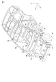
本発明に係る車両前部のフレーム構造の第一の実施形態について、図を参照して説明する。図1に、フロントサイドメンバアッパ10及びフロントピラ12を含む自動車(車両)ほぼ全体のフレーム構造を示す。以下、自動車の進行方向を前方(前側)とし、これを基準に後方(後側)、左右幅方向を定義し、自動車の幅方向の中心に向かう方向を内方向(内側)、自動車の中心から幅方向に広がる方向を外方向(外側)とする。また重力の作用する方向を下方向(下側)、重力に逆らう方向を上方向(上側)とする。図中矢印X、Y及びZは直交する3方向を示し、矢印Xは車両前方、矢印Yは車幅方向左側、矢印Zは車両上方向を指す。尚、左右で同様な構成については適宜説明を省略することがある。
A first embodiment of a vehicle front frame structure according to the present invention will be described with reference to the drawings. FIG. 1 shows a substantially entire frame structure of an automobile (vehicle) including a front side member upper 10 and a
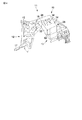
フロントサイドメンバアッパ10とフロントピラ12は、車両の室内空間の前方で、車両の幅方向左右両側にそれぞれ配置されている。図2に車両前部のフレーム構造の一方、つまり車両前部の左方に設けられるフロントサイドメンバアッパ10及びフロントピラ12からなる前左フレーム11を示す。尚、前右フレームは、前左フレームと左右を反転したほぼ同一の構造を有しており、その説明は省略する。
The front side member upper 10 and the
前左フレーム11は、上端が、(左)フロントピラーアッパー14に接続し、下端が、(左)サイドシル16に接続し、前端が前方に延び、フロントサイドメンバロア20に連結している。
The front
図3に、前左フレーム11の分解図を示し、図中の右側に、フロントピラ12を示す。フロントピラ12は、主に縦方向に延設された部材であり、上端に接続部15を有し、下部に接続部17を有している。接続部15には、前述したようにフロントピラーアッパー14の下端が、また接続部17には、サイドシル16の前端がそれぞれ溶接等により一体に接続される。またフロントピラ12の上部前方には、接続部18が形成してある。接続部18は、平坦に形成された端面であり、接続部18の左側、すなわち車両外側には、前方に延びる覆い板22が設けられている。覆い板22は、板状の部材で、フロントピラ12にフロントサイドメンバアッパ10を組み付けると、後述するフロントサイドメンバアッパ10の切り欠き部分24に対応するように形成してある。
FIG. 3 shows an exploded view of the front
またフロントピラ12は、車両の内外方向、すなわち図中Aで示す方向をダイカストの型抜き方向とした、アルミダイキャスト材などの軽合金鋳物からなる構造部材であり、覆い板22を含めて一体に成形されている。
Further, the
図3の左側に、フロントサイドメンバアッパ10を示す。フロントサイドメンバアッパ10は、図の右方、つまり車両の後方側に基端部26を有し、基端部26から車両前方に向けて延びている。基端部26は、フロントピラ12の接続部18に対応し、接続部18に溶接等で固定させるように形成されている。
The front side member upper 10 is shown on the left side of FIG. The front side member upper 10 has a
フロントサイドメンバアッパ10は、基端部26から前方に延びるにつれ、車両の内側に向かい、かつ下方に向かって湾曲し、フロントサイドメンバロア20に前端が連結するように形成してある。(図1参照。)。フロントサイドメンバロア20は、フロントサイドメンバアッパ10の下方にあって、左右のサイドシル16の前端に接続し、サイドシル16とほぼ同一の高さをもって前方に延びている、平面視がほぼH型の部材である。
As the front side member upper 10 extends forward from the
具体的には、フロントサイドメンバアッパ10を接続部18に組み付けると、フロントサイドメンバアッパ10は、車輪Wの上方を越えて車輪Wの内側に入り、車体前方下部においてフロントサイドメンバロア20に接続される。更にフロントサイドメンバアッパ10とフロントサイドメンバロア20が接続された先端部には、フロントバンパービーム30が設けられている。
Specifically, when the front side member upper 10 is assembled to the connecting
基端部26の近傍には、ストラットハウス部28が設けてある。ストラットハウス部28は、3方に設けられた壁体32と、頂板34からなり、一方の面(車両の外側面)が前述した切り欠き部分24となっている。壁体32は、図4にも示すように車両の前方と後方と内側のそれぞれの面に設けてあり、ストラットハウス部28の3方を囲い、頂板34は、それら壁体32の3箇所の頂縁に連結している。図4は、前左フレーム11を車両内側から示した図である。
A
フロントサイドメンバアッパ10は、フロントピラ12と同様、車両の内外方向、すなわち矢印Aの方向を型抜き方向とした、アルミダイキャスト材などの軽合金鋳物からなる構造部材であり、切り欠き部分24は、型抜き方向に若干の抜き勾配をもって形成されたストラットハウス部28の内面に連続して形成されている。すなわち、切り欠き部分24を通って、ストラットハウス部28の内側面を形成する型面(凸状)が、型締めに際してストラットハウス部28の外側面を形成する型面(凹状)内に進入し、また型を開く際に抜き出されるようになっている。頂板34には、取付孔36が形成してある。取付孔36は、前輪Wのショックアブソーバの取付部(図示せず。)に対応しており、取付孔36を介してストラットハウス部28の内側にショックアブソーバが固定される。
Similar to the
次に、前左フレーム11の形成方法について説明する。
上述したように、フロントサイドメンバアッパ10とフロントピラ12を図3に示すようにダイカストでそれぞれ形成する。ダイカストは、前述したようにそれぞれ車両の内外方向を型抜き方向として行われる。
Next, a method for forming the front
As described above, the front side member upper 10 and the
そしてフロントサイドメンバアッパ10の基端部26をフロントピラ12の接続部18に組み付け、接続部18と基端部26の周縁を溶接するとともに、覆い板22と切り欠き部分24の突き合わせ部分を溶接する。これにより、前左フレーム11が一体に形成され、かつ覆い板22と切り欠き部分24が溶接されることによりストラットハウス部28が3方の壁体32と覆い板22により4方が囲まれてた閉断面に形成される。尚、前右フレームも同様にして形成することができる。
And the
したがって、閉断面のストラットハウス部28を有する車両前部のフレーム構造を、ダイカストにより、簡易な工程で、かつフロントサイドメンバアッパ10とフロントピラ12以外の部品を用いることなく、これら部材を接続させて確実に剛性を確保し、かつ安価に構成することができる。
Therefore, the frame structure of the front portion of the vehicle having the
また、覆い板22を切り欠き部分24に合わせることにより、接続部18と基端部26における位置合わせが容易となり、フロントサイドメンバアッパ10とフロントピラ12を正確に、かつ容易に溶接固定できる。
Further, by aligning the
尚、覆い板22と切り欠き部分24は溶接により固定するが、他の部分は、ねじ固定等でもよい。また本発明のフレーム構造の素材は、アルミニウム、あるいはアルミニウム合金等に限定するものではない。更に、切り欠き部分は、車両外側でなく、他の面、例えば車両内側面等に形成してもよい。
The
10…フロントサイドメンバアッパ
11…前左フレーム
12…フロントピラ
15、17、18…接続部
22…覆い板
24…切り欠き部分
28…ストラットハウス部分
32…壁体
DESCRIPTION OF
Claims (4)
前記フロントピラの車両前方側に取り付けられ、前端が、フロントサイドメンバロアに接続されるフロントサイドメンバアッパと、からなる車両前部のフレーム構造において、
前記フロントピラ及び前記フロントサイドメンバアッパは、前記車両の内外方向を型抜き方向としたダイカスト部材であり、
かつ、前記フロントサイドメンバアッパは、ストラットハウス部を備え、
前記ストラットハウス部は、前記ストラットハウス部の周囲を構成する4方の面のうちの3方の面を壁体とし、該4方の面のうちの他の1方の面であって、前記型抜き方向に互いに対向する2つの面のいずれか一方の面を前記ストラットハウス部における型抜きを可能とする切り欠き部分とし、
前記フロントピラは、前記フロントサイドメンバアッパを該フロントピラに組み付けたとき、前記切り欠き部分を塞ぐ覆い板を備え、
少なくとも、前記切り欠き部分に前記覆い板を接合して、前記3方の壁体と前記覆い板による4方の壁体により閉断面のストラットハウス部を形成し、前記フロントピラと前記フロントサイドメンバアッパとを連結させたことを特徴とする車両前部のフレーム構造。 A front pillar that is provided in front of the interior space of the vehicle and is provided in a pair on the left and right in the vehicle width direction, with the upper part connected to the lower end of the front pillar upper and the lower part connected to the front end of the side sill
In the frame structure of the vehicle front portion , which is attached to the vehicle front side of the front pillar, and the front end includes a front side member upper connected to the front side member lower,
The front pillar and the front side member upper are die-cast members whose inside / outside direction of the vehicle is a die cutting direction,
And said front side member up path is provided with a strut house part,
The strut house part is a wall of three faces of four faces constituting the periphery of the strut house part , and is the other one face of the four faces, either side of the two surfaces facing each other in the die cutting direction is a cutout portion to enable demolding of the struts house part,
The Furontopi la, when the front side member upper is assembled to the front Pila, comprising a cover plate for closing the notch portion,
At least the cover plate is joined to the notch, and a strut house portion having a closed cross section is formed by the three walls and the four walls formed by the cover plate, and the front pillar and the front side member are formed. A frame structure of a front portion of a vehicle, characterized in that an upper is connected.
Priority Applications (1)
| Application Number | Priority Date | Filing Date | Title |
|---|---|---|---|
| JP2007094603A JP5332129B2 (en) | 2007-03-30 | 2007-03-30 | Frame structure at the front of the vehicle |
Applications Claiming Priority (1)
| Application Number | Priority Date | Filing Date | Title |
|---|---|---|---|
| JP2007094603A JP5332129B2 (en) | 2007-03-30 | 2007-03-30 | Frame structure at the front of the vehicle |
Publications (2)
| Publication Number | Publication Date |
|---|---|
| JP2008247349A JP2008247349A (en) | 2008-10-16 |
| JP5332129B2 true JP5332129B2 (en) | 2013-11-06 |
Family
ID=39972785
Family Applications (1)
| Application Number | Title | Priority Date | Filing Date |
|---|---|---|---|
| JP2007094603A Active JP5332129B2 (en) | 2007-03-30 | 2007-03-30 | Frame structure at the front of the vehicle |
Country Status (1)
| Country | Link |
|---|---|
| JP (1) | JP5332129B2 (en) |
Cited By (1)
| Publication number | Priority date | Publication date | Assignee | Title |
|---|---|---|---|---|
| US10086881B2 (en) | 2015-12-14 | 2018-10-02 | Hyundai Motor Company | Front vehicle body structure |
Family Cites Families (4)
| Publication number | Priority date | Publication date | Assignee | Title |
|---|---|---|---|---|
| JP3436201B2 (en) * | 1999-09-17 | 2003-08-11 | 日産自動車株式会社 | Structure around the body air box |
| JP3446712B2 (en) * | 2000-03-10 | 2003-09-16 | 日産自動車株式会社 | Car front body structure |
| JP4244666B2 (en) * | 2003-03-14 | 2009-03-25 | マツダ株式会社 | Front body structure of the vehicle |
| JP2006143178A (en) * | 2004-10-19 | 2006-06-08 | Mitsubishi Motors Corp | Front side member structure |
-
2007
- 2007-03-30 JP JP2007094603A patent/JP5332129B2/en active Active
Cited By (1)
| Publication number | Priority date | Publication date | Assignee | Title |
|---|---|---|---|---|
| US10086881B2 (en) | 2015-12-14 | 2018-10-02 | Hyundai Motor Company | Front vehicle body structure |
Also Published As
| Publication number | Publication date |
|---|---|
| JP2008247349A (en) | 2008-10-16 |
Similar Documents
| Publication | Publication Date | Title |
|---|---|---|
| JP4550673B2 (en) | Vehicle subframe | |
| US9517798B2 (en) | Vehicle body structure | |
| KR101703596B1 (en) | Front vehicle body structure | |
| JP5922471B2 (en) | Auto body front structure | |
| JP2009137374A (en) | Vehicle body structure | |
| WO2014125723A1 (en) | Vehicle damper housing structure | |
| JP5639936B2 (en) | Body side structure | |
| JP2006062561A (en) | Impact absorbing structure of vehicle | |
| JP5140093B2 (en) | Bumper structure | |
| JP2009083529A (en) | Bumper device for vehicle | |
| JP7087973B2 (en) | Body structure | |
| JP2005162049A (en) | Shock absorbing member for vehicle | |
| JP5332129B2 (en) | Frame structure at the front of the vehicle | |
| JP4026522B2 (en) | Body front structure | |
| JP4639976B2 (en) | Rear structure of the car body | |
| JP5688394B2 (en) | Body front structure | |
| JP2020082859A (en) | Vehicle front part structure | |
| JP5668583B2 (en) | Lower body structure | |
| JP2017001515A (en) | Front body structure of automobile | |
| JP7085517B2 (en) | Body front structure | |
| JP5026136B2 (en) | Body frame structure | |
| JP2018016284A (en) | Vehicle rear part structure | |
| JP2020090255A (en) | Vehicle body structure | |
| JP5548741B2 (en) | Body front structure | |
| JP5951459B2 (en) | Car cowl structure |
Legal Events
| Date | Code | Title | Description |
|---|---|---|---|
| A621 | Written request for application examination |
Free format text: JAPANESE INTERMEDIATE CODE: A621 Effective date: 20100330 |
|
| A711 | Notification of change in applicant |
Free format text: JAPANESE INTERMEDIATE CODE: A711 Effective date: 20100330 |
|
| A521 | Written amendment |
Free format text: JAPANESE INTERMEDIATE CODE: A821 Effective date: 20100331 |
|
| A977 | Report on retrieval |
Free format text: JAPANESE INTERMEDIATE CODE: A971007 Effective date: 20111219 |
|
| A131 | Notification of reasons for refusal |
Free format text: JAPANESE INTERMEDIATE CODE: A131 Effective date: 20120110 |
|
| A521 | Written amendment |
Free format text: JAPANESE INTERMEDIATE CODE: A523 Effective date: 20120312 |
|
| A521 | Written amendment |
Free format text: JAPANESE INTERMEDIATE CODE: A523 Effective date: 20120409 |
|
| RD03 | Notification of appointment of power of attorney |
Free format text: JAPANESE INTERMEDIATE CODE: A7423 Effective date: 20120912 |
|
| A131 | Notification of reasons for refusal |
Free format text: JAPANESE INTERMEDIATE CODE: A131 Effective date: 20121030 |
|
| A521 | Written amendment |
Free format text: JAPANESE INTERMEDIATE CODE: A523 Effective date: 20121221 |
|
| TRDD | Decision of grant or rejection written | ||
| A01 | Written decision to grant a patent or to grant a registration (utility model) |
Free format text: JAPANESE INTERMEDIATE CODE: A01 Effective date: 20130702 |
|
| A61 | First payment of annual fees (during grant procedure) |
Free format text: JAPANESE INTERMEDIATE CODE: A61 Effective date: 20130715 |
|
| R151 | Written notification of patent or utility model registration |
Ref document number: 5332129 Country of ref document: JP Free format text: JAPANESE INTERMEDIATE CODE: R151 |
|
| S531 | Written request for registration of change of domicile |
Free format text: JAPANESE INTERMEDIATE CODE: R313531 |
|
| R350 | Written notification of registration of transfer |
Free format text: JAPANESE INTERMEDIATE CODE: R350 |