JP5331068B2 - Numerical controller - Google Patents
Numerical controller Download PDFInfo
- Publication number
- JP5331068B2 JP5331068B2 JP2010171050A JP2010171050A JP5331068B2 JP 5331068 B2 JP5331068 B2 JP 5331068B2 JP 2010171050 A JP2010171050 A JP 2010171050A JP 2010171050 A JP2010171050 A JP 2010171050A JP 5331068 B2 JP5331068 B2 JP 5331068B2
- Authority
- JP
- Japan
- Prior art keywords
- command
- unit time
- deceleration
- acceleration
- movement
- Prior art date
- Legal status (The legal status is an assumption and is not a legal conclusion. Google has not performed a legal analysis and makes no representation as to the accuracy of the status listed.)
- Expired - Fee Related
Links
- 230000033001 locomotion Effects 0.000 claims abstract description 300
- 230000008859 change Effects 0.000 claims abstract description 141
- 238000012546 transfer Methods 0.000 claims abstract description 90
- 238000012545 processing Methods 0.000 claims abstract description 20
- 230000004044 response Effects 0.000 claims abstract description 15
- 238000003860 storage Methods 0.000 claims abstract description 10
- 230000001133 acceleration Effects 0.000 claims description 240
- 238000004364 calculation method Methods 0.000 claims description 140
- 238000003754 machining Methods 0.000 claims description 88
- 230000007423 decrease Effects 0.000 claims description 14
- 238000000034 method Methods 0.000 abstract description 70
- 230000008569 process Effects 0.000 abstract description 58
- 230000006870 function Effects 0.000 description 105
- 238000012544 monitoring process Methods 0.000 description 50
- 230000004043 responsiveness Effects 0.000 description 12
- 238000012508 change request Methods 0.000 description 11
- 230000001788 irregular Effects 0.000 description 11
- 230000008054 signal transmission Effects 0.000 description 9
- 230000036461 convulsion Effects 0.000 description 7
- 230000035939 shock Effects 0.000 description 7
- 238000009434 installation Methods 0.000 description 3
- 238000003825 pressing Methods 0.000 description 3
- 238000005520 cutting process Methods 0.000 description 2
- 230000003247 decreasing effect Effects 0.000 description 2
- 238000010586 diagram Methods 0.000 description 2
- 230000004069 differentiation Effects 0.000 description 2
- 238000005516 engineering process Methods 0.000 description 2
- 230000008901 benefit Effects 0.000 description 1
- 238000009795 derivation Methods 0.000 description 1
- 230000000116 mitigating effect Effects 0.000 description 1
- 238000012986 modification Methods 0.000 description 1
- 230000004048 modification Effects 0.000 description 1
Images


Classifications
-
- G—PHYSICS
- G05—CONTROLLING; REGULATING
- G05B—CONTROL OR REGULATING SYSTEMS IN GENERAL; FUNCTIONAL ELEMENTS OF SUCH SYSTEMS; MONITORING OR TESTING ARRANGEMENTS FOR SUCH SYSTEMS OR ELEMENTS
- G05B19/00—Programme-control systems
- G05B19/02—Programme-control systems electric
- G05B19/18—Numerical control [NC], i.e. automatically operating machines, in particular machine tools, e.g. in a manufacturing environment, so as to execute positioning, movement or co-ordinated operations by means of programme data in numerical form
- G05B19/402—Numerical control [NC], i.e. automatically operating machines, in particular machine tools, e.g. in a manufacturing environment, so as to execute positioning, movement or co-ordinated operations by means of programme data in numerical form characterised by control arrangements for positioning, e.g. centring a tool relative to a hole in the workpiece, additional detection means to correct position
-
- G—PHYSICS
- G05—CONTROLLING; REGULATING
- G05B—CONTROL OR REGULATING SYSTEMS IN GENERAL; FUNCTIONAL ELEMENTS OF SUCH SYSTEMS; MONITORING OR TESTING ARRANGEMENTS FOR SUCH SYSTEMS OR ELEMENTS
- G05B19/00—Programme-control systems
- G05B19/02—Programme-control systems electric
- G05B19/18—Numerical control [NC], i.e. automatically operating machines, in particular machine tools, e.g. in a manufacturing environment, so as to execute positioning, movement or co-ordinated operations by means of programme data in numerical form
- G05B19/416—Numerical control [NC], i.e. automatically operating machines, in particular machine tools, e.g. in a manufacturing environment, so as to execute positioning, movement or co-ordinated operations by means of programme data in numerical form characterised by control of velocity, acceleration or deceleration
-
- G—PHYSICS
- G05—CONTROLLING; REGULATING
- G05B—CONTROL OR REGULATING SYSTEMS IN GENERAL; FUNCTIONAL ELEMENTS OF SUCH SYSTEMS; MONITORING OR TESTING ARRANGEMENTS FOR SUCH SYSTEMS OR ELEMENTS
- G05B2219/00—Program-control systems
- G05B2219/30—Nc systems
- G05B2219/43—Speed, acceleration, deceleration control ADC
- G05B2219/43062—Maximum acceleration, limit
-
- G—PHYSICS
- G05—CONTROLLING; REGULATING
- G05B—CONTROL OR REGULATING SYSTEMS IN GENERAL; FUNCTIONAL ELEMENTS OF SUCH SYSTEMS; MONITORING OR TESTING ARRANGEMENTS FOR SUCH SYSTEMS OR ELEMENTS
- G05B2219/00—Program-control systems
- G05B2219/30—Nc systems
- G05B2219/43—Speed, acceleration, deceleration control ADC
- G05B2219/43065—Limitation of jerk
-
- G—PHYSICS
- G05—CONTROLLING; REGULATING
- G05B—CONTROL OR REGULATING SYSTEMS IN GENERAL; FUNCTIONAL ELEMENTS OF SUCH SYSTEMS; MONITORING OR TESTING ARRANGEMENTS FOR SUCH SYSTEMS OR ELEMENTS
- G05B2219/00—Program-control systems
- G05B2219/30—Nc systems
- G05B2219/43—Speed, acceleration, deceleration control ADC
- G05B2219/43102—Time constant acceleration, deceleration as function of machining conditions
-
- G—PHYSICS
- G05—CONTROLLING; REGULATING
- G05B—CONTROL OR REGULATING SYSTEMS IN GENERAL; FUNCTIONAL ELEMENTS OF SUCH SYSTEMS; MONITORING OR TESTING ARRANGEMENTS FOR SUCH SYSTEMS OR ELEMENTS
- G05B2219/00—Program-control systems
- G05B2219/30—Nc systems
- G05B2219/43—Speed, acceleration, deceleration control ADC
- G05B2219/43158—Feedrate override
-
- G—PHYSICS
- G05—CONTROLLING; REGULATING
- G05B—CONTROL OR REGULATING SYSTEMS IN GENERAL; FUNCTIONAL ELEMENTS OF SUCH SYSTEMS; MONITORING OR TESTING ARRANGEMENTS FOR SUCH SYSTEMS OR ELEMENTS
- G05B2219/00—Program-control systems
- G05B2219/30—Nc systems
- G05B2219/43—Speed, acceleration, deceleration control ADC
- G05B2219/43172—Change velocities on the fly during a motion
-
- G—PHYSICS
- G05—CONTROLLING; REGULATING
- G05B—CONTROL OR REGULATING SYSTEMS IN GENERAL; FUNCTIONAL ELEMENTS OF SUCH SYSTEMS; MONITORING OR TESTING ARRANGEMENTS FOR SUCH SYSTEMS OR ELEMENTS
- G05B2219/00—Program-control systems
- G05B2219/30—Nc systems
- G05B2219/50—Machine tool, machine tool null till machine tool work handling
- G05B2219/50103—Restart, reverse, return along machined path, stop
-
- G—PHYSICS
- G05—CONTROLLING; REGULATING
- G05B—CONTROL OR REGULATING SYSTEMS IN GENERAL; FUNCTIONAL ELEMENTS OF SUCH SYSTEMS; MONITORING OR TESTING ARRANGEMENTS FOR SUCH SYSTEMS OR ELEMENTS
- G05B2219/00—Program-control systems
- G05B2219/30—Nc systems
- G05B2219/50—Machine tool, machine tool null till machine tool work handling
- G05B2219/50198—Emergency stop
Abstract
Description
本発明は、数値制御装置に関するものである。 The present invention relates to a numerical control device.
従来の各種工作機械では、ワークやそのワークを加工する工具を移送する移送装置を加工指令プログラム(NCプログラム)に従って数値制御することによりワークの加工が行われている。そして、このような工作機械では、一般的に手動操作によりワークや工具の加減速を伴う動作を指示可能な指示装置が設けられており、オペレータ等がこの指示装置により指示を行うことで前記加工指令プログラムに従ったワークや工具の通常の移動とは別にワークや工具の加減速を伴う動作を実施可能である。 In various conventional machine tools, a workpiece is machined by numerically controlling a transfer device that transfers a workpiece and a tool for machining the workpiece according to a machining command program (NC program). Such a machine tool is generally provided with an instruction device capable of instructing an operation accompanied by acceleration / deceleration of a workpiece or a tool by a manual operation. In addition to the normal movement of the workpiece or tool according to the command program, it is possible to perform an operation involving acceleration / deceleration of the workpiece or tool.
具体的には、工作機械には、前記指示装置として緊急停止装置、再始動装置、オーバーライド装置等が設けられている。緊急停止装置は、ワーク又は工具を移動対象物としてその移動対象物が移送装置によって移送されている時にその移動対象物の移送の緊急停止を指示するためのものである。この緊急停止装置は、緊急停止ボタンを備えており、その緊急停止ボタンが押されることによって、移送装置に移動対象物の移送を緊急に停止するように指示を行う。また、再始動装置は、緊急停止後の移動対象物の再始動を指示するためのものである。この再始動装置は、再始動ボタンを備えており、その再始動ボタンが押されることによって、移送装置に移動対象物の移送の再開を指示する。また、オーバーライド装置は、オーバーライドダイヤルを備えており、そのオーバーライドダイヤルが操作されることによってその操作量に応じて移送装置に移動対象物の移送速度の加減速を指示する。上記緊急停止の場合には、移動対象物の急激な減速を伴い、上記再始動の場合には、移動対象物の急激な加速を伴い、また、上記オーバーライド装置により加減速が指示されると、通常の移動対象物の移動時に比べて急激な加減速が行われる。 Specifically, the machine tool is provided with an emergency stop device, a restart device, an override device, and the like as the instruction device. The emergency stop device is for instructing an emergency stop of the transfer of the moving object when the moving object is transferred by the transfer device with the workpiece or tool as the moving object. This emergency stop device includes an emergency stop button, and when the emergency stop button is pressed, instructs the transfer device to urgently stop the transfer of the moving object. The restart device is for instructing restart of the moving object after the emergency stop. The restart device includes a restart button. When the restart button is pressed, the restart device instructs the transfer device to resume transfer of the moving object. The override device also includes an override dial. When the override dial is operated, the override device instructs the transfer device to accelerate or decelerate the transfer speed of the moving object according to the operation amount. In the case of the emergency stop, accompanied by a rapid deceleration of the moving object, in the case of the restart, accompanied by a rapid acceleration of the moving object, and when the acceleration / deceleration is instructed by the override device, The acceleration / deceleration is performed more rapidly than when a normal moving object is moving.
ところで、工作機械において上記のような移動対象物の加減速を伴う動作が行われるときには、工作機械に機械ショックが与えられる。移動対象物の急激な加減速に起因する機械ショックを低減するための技術は、従来提案されている。その技術の一例としては、加減速フィルタによる補間後加減速がある。この補間後加減速は、加工指令プログラムから補間演算によって得られた移動指令を加減速フィルタにより所定の指令時定数に応じた時間の分遅らせることによって、加工指令プログラムが指示する急激な加減速及び指示装置によって指示される急激な加減速を緩和する技術である。 By the way, when an operation involving acceleration / deceleration of the moving object as described above is performed in the machine tool, a machine shock is applied to the machine tool. Techniques for reducing mechanical shock caused by sudden acceleration / deceleration of a moving object have been proposed. An example of the technique is post-interpolation acceleration / deceleration using an acceleration / deceleration filter. This post-interpolation acceleration / deceleration is a rapid acceleration / deceleration commanded by the machining command program by delaying the movement command obtained by the interpolation calculation from the machining command program by a time corresponding to a predetermined command time constant by an acceleration / deceleration filter. This is a technique for mitigating rapid acceleration / deceleration instructed by an instruction device.
しかし、この補間後加減速では、移動対象物の急激な加減速に起因する機械ショックを緩和できるという利点がある反面、ワークの加工形状の誤差が発生するという欠点がある。具体的には、この補間後加減速は、加工指令プログラムが指示する急激な加減速の緩和と前記指示装置によって指示される急激な加減速の緩和の両方に有効である反面、加工指令プログラムが指示する急激な加減速の緩和に適用されれば、加工指令プログラムが指示する加工形状(加工パス)に対して誤差が発生し、指示装置によって指示される急激な加減速の緩和に適用されれば、加工指令プログラムが指示する急激な加減速を前記補間後加減速で緩和した後の加工パスに対して更なる誤差が発生するため、ワークに思わぬ傷がつく原因になる。 However, this post-interpolation acceleration / deceleration has the advantage that mechanical shocks caused by sudden acceleration / deceleration of the moving object can be mitigated, but has the disadvantage that an error in the workpiece machining shape occurs. Specifically, the post-interpolation acceleration / deceleration is effective for both the rapid acceleration / deceleration instructed by the machining command program and the rapid acceleration / deceleration instructed by the indicating device. If applied to alleviating rapid acceleration / deceleration instructed, an error occurs in the machining shape (machining path) instructed by the machining command program and applied to alleviating rapid acceleration / deceleration instructed by the pointing device. For example, since a further error occurs in the machining path after the rapid acceleration / deceleration instructed by the machining command program is alleviated by the post-interpolation acceleration / deceleration, the workpiece may be damaged unexpectedly.
この問題点に対して、下記特許文献1には、補間後加減速によって発生する加工形状の誤差を補正するために移動対象物の各移動軸間に生じる位相誤差を抹消するための演算を行う技術が提案されている。
In order to solve this problem,
また、下記特許文献2には、補間後加減速を全く用いない加減速技術が提案されている。この加減速技術では、加工指令プログラムから移動対象物の各移動軸毎の移動パルスを算出する前に行う補間前加減速演算により、加工指令プログラムが指示する急激な加減速を緩和した加工パスが予め計算され、その結果、機械ショックを起こさない加工パスで移動対象物を移動させることが可能となる。このため、この加減速技術によれば、上記のような補間後加減速に起因する誤差を生じることなく、移動対象物の急激な加減速に起因する機械ショックを低減可能である。
しかし、上記特許文献1及び特許文献2のいずれの技術においても、前記指示装置による急激な加減速の緩和を行うには、その要求に応じて再計算する演算が複雑となり、前記指示装置により移動対象物の加減速を伴う動作が指示されてから実際にその移動対象物の動作が行われるまでの応答性が悪化するという問題点がある。
However, in any of the techniques of
具体的には、工作機械において上記のような緊急停止、再始動に伴う加速、オーバーライド装置による加減速等の加減速を伴う動作が行われるときには、その加減速の動作の指示(緊急停止ボタンや再始動ボタンのオン、オーバーライドダイヤルの操作)が行われてから迅速に、かつ、予定されている加工パスからずれることなくその加減速動作が実行されることが要求されるが、上記特許文献1及び上記特許文献2のいずれの技術においても、移動指令の演算が複雑であることからその演算に時間が掛かり、その結果、加減速動作の指示が行われてから実際にその加減速動作が実施されるまでの応答性が悪化する。
Specifically, when an operation involving acceleration / deceleration, such as acceleration as described above, acceleration due to restart, acceleration / deceleration by an override device, is performed on a machine tool, an instruction for the acceleration / deceleration operation (such as an emergency stop button or The acceleration / deceleration operation is required to be executed promptly after the restart button is turned on and the override dial is operated, and without deviating from the scheduled machining path. In any of the techniques of
本発明は、上記の課題を解決するためになされたものであり、その目的は、工作機械においてワークの加工時における移動対象物の通常の移送とは別にその移動対象物の速度変化を伴う動作を実施する場合に、移動対象物が加工指令プログラムによって指示される加工パスからずれるのを防ぎつつ、その速度変化を伴う動作が指示されてからその動作が実行されるまでの応答性を向上することが可能な数値制御装置を提供することである。 The present invention has been made to solve the above-described problems, and its object is to perform an operation accompanied by a speed change of the moving object in addition to the normal transfer of the moving object when machining a workpiece in a machine tool. When the operation is performed, the moving object is prevented from deviating from the machining path instructed by the machining command program, and the responsiveness until the operation is executed after the operation with the speed change is instructed is improved. It is to provide a numerical control device that can be used.
上記目的を達成するために、本発明による数値制御装置は、ワーク又はそのワークを加工する工具を移動対象物として前記ワークの加工時に前記移動対象物を移送する複数の移送装置と、前記ワークの加工時における前記移動対象物の通常の移送とは別に当該移動対象物の速度変化を伴う動作を指示するための特別指令を外部から入力するための特別指令入力装置とを備え、前記各移送装置は、前記移動対象物を支持する支持体と、その支持体を特定の移動軸方向に移送することにより前記移動対象物を移送する駆動装置とをそれぞれ有する工作機械に設けられ、前記各移送装置の数値制御を行う数値制御装置であって、前記ワークの加工時に前記移動対象物が基準時刻の経過に伴って移動すべき経路を表す加工パスが規定された加工指令プログラムを記憶する記憶部と、前記加工パスに基づいてある設定単位時間当たりの前記各支持体の対応する前記移動軸方向への移動量をそれぞれ算出する演算部と、前記各駆動装置の駆動の基準となる基準単位時間毎にその各駆動装置を駆動してその各駆動装置に前記基準単位時間当たりに前記演算部によって算出された前記移動量の分、対応する前記支持体を対応する前記移動軸方向へ移送させる駆動制御部とを備え、前記特別指令入力装置は、前記特別指令として前記移動対象物の移動を緊急に減速させて停止させるための緊急停止指令を入力するための停止指令入力装置を含み、前記演算部は、前記設定単位時間を前記基準単位時間とは別の単位時間として設定し、前記停止指令入力装置に前記緊急停止指令が入力されたことに応じて、前記設定単位時間の長さが所定の減速停止期間に前記停止指令入力装置への前記緊急停止指令の入力直前の状態における長さから0まで減少するような停止時単位時間変動関数に基づいて前記減速停止期間における前記設定単位時間を算出するとともにその算出した設定単位時間当たりの前記各支持体の対応する前記移動軸方向への移動量を前記加工パスから算出する。
In order to achieve the above object, a numerical control apparatus according to the present invention includes a plurality of transfer devices that transfer a moving object at the time of processing the workpiece, using a workpiece or a tool for processing the workpiece as a moving object, In addition to the normal transfer of the moving object during processing, a special command input device for inputting a special command for instructing an operation accompanied by a speed change of the moving object from the outside. Are provided in machine tools each having a support for supporting the moving object, and a drive device for transferring the moving object by transferring the support in a specific movement axis direction. A numerical control device for performing numerical control of a machining command program that defines a machining path that represents a path that the moving object should move with the lapse of a reference time when machining the workpiece. A storage unit for storing a gram, and said processing said per set unit time is based on a path calculation unit configured to calculate the amount of movement of the corresponding said moving axis direction of each support, the drive of each drive unit Each of the driving devices is driven every reference unit time serving as a reference, and the corresponding support is moved to the driving device corresponding to the amount of movement calculated by the calculation unit per reference unit time. A drive control unit for moving the moving object in the axial direction, and the special command input device inputs a stop command for inputting an emergency stop command for urgently decelerating and stopping the movement of the moving object as the special command. includes a device, the computing unit, depending on the fact that the set unit time is set as a separate unit time and the reference unit time, the emergency stop command to the stop command input device is inputted The length of the set unit time based on the stop time of the unit time variation function that decreases from said length in the state of the input immediately before the
この数値制御装置では、特別指令入力装置に特別指令を入力して工作機械に移動対象物の速度変化を伴うイレギュラーな動作を実施させる際、各移動軸方向に共通の設定単位時間の長さが前記特別指令の入力直前の状態における長さからその特別指令が指示する速度変化に応じた長さに変化させられるとともに、加工パスから算出されたその変化後の設定単位時間当たりの各支持体の対応する移動軸方向への移動量に応じて各支持体が移送される。このため、ワークの加工時における移動対象物の通常の移送とは別にその移動対象物のイレギュラーな速度変化を伴う動作を実行させる場合に、移動対象物が加工パスからずれるのを防ぐことができる。 In this numerical control device, when a special command is input to the special command input device to cause the machine tool to perform an irregular operation accompanied by a change in the speed of the moving object, the length of the set unit time common to each moving axis direction Is changed from the length in the state immediately before the input of the special command to the length corresponding to the speed change instructed by the special command, and each support body per set unit time after the change calculated from the machining path Each support is transferred according to the amount of movement in the corresponding movement axis direction. For this reason, it is possible to prevent the moving object from deviating from the machining path when an operation involving irregular speed change of the moving object is executed separately from the normal transfer of the moving object during workpiece processing. it can.
具体的には、この数値制御装置のように前記特別指令に応じて各移動軸方向に共通の設定単位時間の長さを変化させる場合には、加工パスからその設定単位時間当たりに算出される各移動軸方向への支持体の移動量が加工パスによって規定される各移動軸間の相対的な位置関係が維持された状態で算出される。このため、その算出された設定単位時間当たりの各移動軸方向への移動量に応じて対応する支持体が駆動装置によって移送されると、加工パスによって規定される各移動軸間の相対的な位置関係が維持された状態で移動対象物の速度変化を伴う動作が実施される。その結果、上記のようなイレギュラーな移動対象物の速度変化を伴う動作が実施されたとしても、移動対象物が前記加工パスからずれるのを防ぐことができる。 Specifically, when the common set unit time length is changed in the direction of each moving axis in accordance with the special command as in this numerical control device, it is calculated per set unit time from the machining path. The amount of movement of the support in the direction of each movement axis is calculated in a state where the relative positional relationship between the movement axes defined by the machining path is maintained. For this reason, when the corresponding support is transferred by the driving device in accordance with the calculated movement amount in the direction of each movement axis per set unit time, the relative movement between the movement axes defined by the machining path is determined. An operation involving a change in the speed of the moving object is performed in a state where the positional relationship is maintained. As a result, even if the operation accompanied by the irregular speed change of the moving object as described above is performed, the moving object can be prevented from deviating from the processing path.
また、この数値制御装置では、前記補間後加減速によって生じる誤差を抹消するための演算を別途行う上記特許文献1の技術や前記補間前加減速演算を行う上記特許文献2の技術のように複雑な処理を特別指令入力装置に特別指令が入力された際に行わなくても、各移動軸方向に共通の設定単位時間の長さを変化させるという単純な処理で移動対象物が加工パスからずれるのを防ぎつつその移動対象物のイレギュラーな速度変化を伴う動作を実施することができるため、特別指令入力装置に特別指令が入力されることによって移動対象物の速度変化を伴う動作が指示されてから移送装置が実際にその移動対象物の速度変化を伴う動作を実行するまでの応答性を向上することができる。また、この数値制御装置では、駆動装置の駆動の基準となる基準単位時間に影響を与えずに、移動対象物のイレギュラーな速度変化を伴う動作を実施するための各駆動装置による対応する支持体の基準単位時間当たりの移送量(移動量)を算出して、その移送量に応じた各支持体の対応する移動軸方向への移送を行うことができるため、各駆動装置の駆動に影響を与えることなく、移動対象物のイレギュラーな速度変化を伴う動作を実施することができる。また、この数値制御装置では、停止指令入力装置に緊急停止指令を入力することにより、前記減速停止期間に各支持体の対応する移動軸方向への設定単位時間当たりの移動量を0まで減少させて移動対象物を停止させることができる。そして、この構成では、各移動軸方向に共通の設定単位時間の長さを0まで減少させることによって各支持体の対応する移動軸方向への設定単位時間当たりの移動量を0まで減少させるので、移動対象物を緊急停止させる際にその移動対象物が加工パスからずれるのを防ぎつつ、緊急停止指令が停止指令入力装置に入力されてから移動対象物の緊急停止が実際に実行されるまでの応答性を向上することができる。
In addition, in this numerical control device, such a technique as that of the above-described
上記数値制御装置において、前記特別指令入力装置は、前記特別指令として移動停止した前記移動対象物の移動を再開させて加速させるための再始動指令を入力するための再始動指令入力装置を含み、前記演算部は、前記停止指令入力装置に前記緊急停止指令が入力された後に前記再始動指令入力装置に前記再始動指令が入力されたことに応じて、前記設定単位時間の長さが所定の再始動加速期間に0から特定の長さまで増加するような再始動時単位時間変動関数に基づいて前記再始動加速期間における前記設定単位時間を算出し、その算出した設定単位時間当たりの前記各支持体の対応する前記移動軸方向への移動量を前記加工パスから算出することが好ましい。 In the numerical control device , the special command input device includes a restart command input device for inputting a restart command for resuming and accelerating the movement of the moving object that has stopped moving as the special command, The calculation unit has a predetermined length of the set unit time in response to the restart command being input to the restart command input device after the emergency stop command is input to the stop command input device. The set unit time in the restart acceleration period is calculated based on a restart unit time variation function that increases from 0 to a specific length during the restart acceleration period, and each support per calculated set unit time is calculated. It is preferable to calculate the movement amount of the body in the corresponding movement axis direction from the machining path.
この構成によれば、前記緊急停止指令により移動対象物が停止している状態で再始動指令入力装置に再始動指令を入力することにより、前記再始動加速期間に各支持体の対応する移動軸方向への設定単位時間当たりの移動量を0からその設定単位時間の増加に応じた特定の移動量まで増加させて移動対象物の加速を伴う再始動を実施することができる。そして、この構成では、各移動軸方向に共通の設定単位時間の長さを0から特定の長さまで増加させることによって各支持体の対応する移動軸方向への設定単位時間当たりの移動量を特定の移動量まで増加させるので、移動停止した移動対象物を再始動させる際にその移動対象物が加工パスからずれるのを防ぎつつ、再始動指令が再始動指令入力装置に入力されてから移動対象物の再始動及び加速が実際に実行されるまでの応答性を向上することができる。 According to this configuration, by inputting a restart command to the restart command input device in a state where the moving object is stopped by the emergency stop command, the corresponding moving shaft of each support body during the restart acceleration period. The moving amount per set unit time in the direction can be increased from 0 to a specific moving amount corresponding to the increase in the set unit time, and restarting with acceleration of the moving object can be performed. In this configuration, the amount of movement per set unit time in the corresponding movement axis direction of each support is specified by increasing the length of the set unit time common to each movement axis direction from 0 to a specific length. Therefore, when restarting a moving object that has stopped moving, the moving object is prevented from deviating from the machining path, while the restart command is input to the restart command input device. Responsiveness until the actual restart and acceleration of the object is actually performed can be improved.
上記数値制御装置において、前記特別指令入力装置は、前記特別指令として前記移動対象物の移動速度を上昇させる指示とその移動速度の上昇率である加速率の情報を含む加速指令又は前記移動対象物の移動速度を低下させる指示とその移動速度の低下率である減速率の情報を含む減速指令を入力することが可能な速度変更指令入力装置を含み、前記演算部は、前記速度変更指令入力装置に前記加速指令が入力されたことに応じて、前記設定単位時間の長さが所定の加速期間に前記速度変更指令入力装置への前記加速指令の入力直前の状態における長さから前記加速指令に含まれる前記加速率に応じた長さまで増加するような加速時単位時間変動関数に基づいて前記加速期間における前記設定単位時間を算出し、その算出した設定単位時間当たりの前記各支持体の対応する前記移動軸方向への移動量を前記加工パスから算出する一方、前記速度変更指令入力装置に前記減速指令が入力されたことに応じて、前記設定単位時間の長さが所定の減速期間に前記速度変更指令入力装置への前記減速指令の入力直前の状態における長さから前記減速指令に含まれる前記減速率に応じた長さまで減少するような減速時単位時間変動関数に基づいて前記減速期間における前記設定単位時間を算出し、その算出した設定単位時間当たりの前記各支持体の対応する前記移動軸方向への移動量を前記加工パスから算出することが好ましい。 In the numerical control device, the special command input device includes an instruction to increase the moving speed of the moving object as the special command and an acceleration command including information on an acceleration rate that is an increase rate of the moving speed or the moving object. A speed change command input device capable of inputting a deceleration command including an instruction to reduce the moving speed of the vehicle and a deceleration rate information that is a rate of decrease in the moving speed, and the calculation unit includes the speed change command input device. In response to the input of the acceleration command, the length of the set unit time is changed from the length in the state immediately before the input of the acceleration command to the speed change command input device during the predetermined acceleration period. The set unit time in the acceleration period is calculated based on an acceleration time unit variation function that increases to a length corresponding to the included acceleration rate, and the calculated set unit time The amount of movement of each support in the direction of the corresponding movement axis is calculated from the machining path, while the set unit time of the set unit time is calculated in response to the input of the deceleration command to the speed change command input device. Unit time during deceleration such that the length decreases from the length immediately before the input of the deceleration command to the speed change command input device to a length corresponding to the deceleration rate included in the deceleration command during a predetermined deceleration period Preferably, the set unit time in the deceleration period is calculated based on a variation function, and the movement amount of the support in the moving axis direction corresponding to the calculated set unit time is calculated from the machining path. .
この構成によれば、速度変更指令入力装置に加速指令を入力することにより、前記加速期間に各支持体の対応する移動軸方向への設定単位時間当たりの移動量を速度変更指令入力装置への加速指令の入力直前の移動量から加速指令に含まれる加速率に応じた移動量まで増加させて移動対象物の加速を実施することができる一方、速度変更指令入力装置に減速指令を入力することにより、前記減速期間に各支持体の対応する移動軸方向への設定単位時間当たりの移動量を速度変更指令入力装置への減速指令の入力直前の移動量から減速指令に含まれる減速率に応じた移動量まで減少させて移動対象物の減速を実施することができる。そして、この構成では、各移動軸方向に共通の設定単位時間を増加させることによって各支持体の対応する移動軸方向への設定単位時間当たりの移動量を増加させ、また、各移動軸方向に共通の設定単位時間を減少させることによって各支持体の対応する移動軸方向への設定単位時間当たりの移動量を減少させるので、ワークの加工時に移動対象物の移動速度を速度変更指令入力装置への加速指令又は減速指令の入力により変動させる際にその移動対象物が加工パスからずれるのを防ぎつつ、加速指令又は減速指令が速度変更指令入力装置に入力されてから移動対象物の加速又は減速が実際に実行されるまでの応答性を向上することができる。 According to this configuration, by inputting an acceleration command to the speed change command input device, the amount of movement per set unit time in the direction of the corresponding movement axis of each support during the acceleration period is input to the speed change command input device. The moving object can be accelerated by increasing the moving amount just before the input of the acceleration command to the moving amount corresponding to the acceleration rate included in the acceleration command, and the deceleration command is input to the speed change command input device. The amount of movement per set unit time in the corresponding movement axis direction of each support during the deceleration period is determined according to the deceleration rate included in the deceleration command from the amount of movement immediately before the input of the deceleration command to the speed change command input device. The moving object can be decelerated by reducing the amount of movement. In this configuration, the amount of movement per set unit time in the corresponding movement axis direction of each support is increased by increasing the common setting unit time in each movement axis direction, and in each movement axis direction. By reducing the common set unit time, the amount of movement per set unit time in the direction of the corresponding movement axis of each support is reduced, so the moving speed of the moving object can be transferred to the speed change command input device when machining the workpiece. Acceleration or deceleration of the moving object after the acceleration command or deceleration command is input to the speed change command input device while preventing the moving object from deviating from the machining path when fluctuating due to the input of the acceleration command or deceleration command. It is possible to improve the responsiveness until the process is actually executed.
また、本発明による数値制御装置は、ワーク又はそのワークを加工する工具を移動対象物として前記ワークの加工時に前記移動対象物を移送する複数の移送装置と、前記ワークの加工時における前記移動対象物の通常の移送とは別に当該移動対象物の速度変化を伴う動作を指示するための特別指令を外部から入力するための特別指令入力装置とを備え、前記各移送装置は、前記移動対象物を支持する支持体と、その支持体を特定の移動軸方向に移送することにより前記移動対象物を移送する駆動装置とをそれぞれ有する工作機械に設けられ、前記各移送装置の数値制御を行う数値制御装置であって、前記ワークの加工時に前記移動対象物が基準時刻の経過に伴って移動すべき経路を表す加工パスが規定された加工指令プログラムを記憶する記憶部と、前記加工パスに基づいてある設定単位時間当たりの前記各支持体の対応する前記移動軸方向への移動量をそれぞれ算出する演算部と、前記各駆動装置の駆動の基準となる基準単位時間毎にその各駆動装置を駆動してその各駆動装置に前記基準単位時間当たりに前記演算部によって算出された前記移動量の分、対応する前記支持体を対応する前記移動軸方向へ移送させる駆動制御部とを備え、前記特別指令入力装置は、前記特別指令として前記移動対象物の移動速度を上昇させる指示とその移動速度の上昇率である加速率の情報を含む加速指令又は前記移動対象物の移動速度を低下させる指示とその移動速度の低下率である減速率の情報を含む減速指令を入力することが可能な速度変更指令入力装置を含み、前記演算部は、前記設定単位時間を前記基準単位時間とは別の単位時間として設定し、前記速度変更指令入力装置に前記加速指令が入力されたことに応じて、前記設定単位時間の長さが所定の加速期間に前記速度変更指令入力装置への前記加速指令の入力直前の状態における長さから前記加速指令に含まれる前記加速率に応じた長さまで増加するような加速時単位時間変動関数に基づいて前記加速期間における前記設定単位時間を算出するとともにその算出した設定単位時間当たりの前記各支持体の対応する前記移動軸方向への移動量を前記加工パスから算出する一方、前記速度変更指令入力装置に前記減速指令が入力されたことに応じて、前記設定単位時間の長さが所定の減速期間に前記速度変更指令入力装置への前記減速指令の入力直前の状態における長さから前記減速指令に含まれる前記減速率に応じた長さまで減少するような減速時単位時間変動関数に基づいて前記減速期間における前記設定単位時間を算出するとともにその算出した設定単位時間当たりの前記各支持体の対応する前記移動軸方向への移動量を前記加工パスから算出する。Further, the numerical control device according to the present invention includes a plurality of transfer devices that transfer a moving object when the workpiece or a tool that processes the workpiece is a moving object, and the moving object when the workpiece is processed. A special command input device for inputting from the outside a special command for instructing an operation accompanied by a speed change of the moving object separately from the normal transfer of the object, and each of the transfer devices includes the moving object Are provided in a machine tool each having a support for supporting the moving object and a driving device for transferring the moving object by transferring the support in a specific movement axis direction, and performing numerical control of each of the transfer devices. A control device that stores a machining command program that defines a machining path that represents a path that the moving object should move with the passage of a reference time when machining the workpiece. A calculation unit for calculating the amount of movement of each support in the corresponding movement axis direction per set unit time based on the machining path, and a reference unit serving as a reference for driving each driving device Each drive device is driven every time, and the corresponding support body is moved in the direction of the corresponding movement axis by the amount of movement calculated by the calculation unit per reference unit time. The special command input device includes an instruction to increase the moving speed of the moving object as the special command and an acceleration command including information on an acceleration rate that is an increase rate of the moving speed or the moving target. A speed change command input device capable of inputting an instruction to reduce the moving speed of an object and a deceleration command including information on a deceleration rate that is a rate of decrease in the moving speed, and the calculation unit includes the setting unit. The time is set as a unit time different from the reference unit time, and when the acceleration command is input to the speed change command input device, the length of the set unit time is set to the speed within a predetermined acceleration period. Based on the unit time variation function at the time of acceleration that increases from the length in the state immediately before the input of the acceleration command to the change command input device to the length according to the acceleration rate included in the acceleration command, in the acceleration period While calculating the set unit time and calculating the corresponding movement amount of each support in the moving axis direction per set unit time from the machining path, the deceleration change command is input to the speed change command input device. Is input from the length in the state immediately before the input of the deceleration command to the speed change command input device during a predetermined deceleration period. The set unit time in the deceleration period is calculated based on a unit time variation function during deceleration that decreases to a length corresponding to the deceleration rate included in the deceleration command, and each of the supports per calculated set unit time The amount of movement in the direction of the corresponding movement axis is calculated from the machining path.
以上説明したように、本発明によれば、工作機械においてワークの加工時における移動対象物の通常の移送とは別にその移動対象物の速度変化を伴う動作を実施する場合に、移動対象物が加工指令プログラムによって指示される加工パスからずれるのを防ぎつつ、その速度変化を伴う動作が指示されてからその動作が実行されるまでの応答性を向上することができる。 As described above, according to the present invention, when performing an operation accompanied by a speed change of the moving object in addition to the normal transfer of the moving object at the time of machining the workpiece in the machine tool, the moving object is While preventing deviation from the machining path instructed by the machining command program, it is possible to improve the responsiveness from when the operation accompanied by the speed change is instructed until the operation is executed.
以下、本発明の実施形態を図面を参照して説明する。 Hereinafter, embodiments of the present invention will be described with reference to the drawings.
まず、図1及び図2を参照して、本発明の一実施形態による数値制御装置2が適用される工作機械の構成について説明する。
First, with reference to FIG.1 and FIG.2, the structure of the machine tool to which the
本実施形態による数値制御装置2(図2参照)が設けられている工作機械は、被加工物であるワーク100を切削加工するためのものであり、ワーク移送装置102と、コラム104と、工具105と、工具鉛直移送装置106と、工具第1水平移送装置108と、工具第2水平移送装置110と、主軸ヘッド112と、制御盤114とを備えている。なお、ワーク移送装置102、工具鉛直移送装置106、工具第1水平移送装置108及び工具第2水平移送装置110は、それぞれ本発明の移送装置の概念に含まれるものである。
A machine tool provided with a numerical control device 2 (see FIG. 2) according to the present embodiment is for cutting a
ワーク移送装置102は、ワーク100を図1の紙面に垂直な方向であるX軸方向に移送するための装置である。このワーク移送装置102は、所定の設置場所上に固設されるベース102aと、そのベース102a上にX軸方向に移動可能に設けられるワーク支持体102bと、そのワーク支持体102bをX軸方向に移送するワーク駆動装置102c(図2参照)とを有する。ワーク支持体102bは、ワーク100を支持するものである。ワーク100は、このワーク支持体102b上に垂直に立った状態で設置される。ワーク駆動装置102cは、駆動源としてのサーボモータを有する。なお、前記X軸は、本発明の移動軸の概念に含まれるものであり、ワーク支持体102bは、本発明の支持体の概念に含まれるものであり、ワーク駆動装置102cは、本発明の駆動装置の概念に含まれるものである。
The
コラム104は、前記ベース102aの設置場所から水平方向でかつ前記X軸と直交する方向に離間した設置場所に立設されており、鉛直方向に延びている。
The
工具鉛直移送装置106は、コラム104に設けられており、ワーク100を切削加工するための工具105を鉛直方向に延びるY軸方向に移送するための装置である。この工具鉛直移送装置106は、Y軸方向に移動可能にコラム104に取り付けられる鉛直支持体106aと、コラム104に設けられ、鉛直支持体106aをコラム104に沿ってY軸方向に移送する鉛直駆動装置106b(図2参照)とを有する。鉛直支持体106aは、工具第1水平移送装置108を支持しており、この工具第1水平移送装置108は、後述するように工具第2水平移送装置110及び主軸ヘッド112を介して工具105を支持するため、鉛直支持体106aは間接的に工具105を支持する。鉛直駆動装置106bは、駆動源としてのサーボモータを有する。なお、前記Y軸方向は、本発明の移動軸の概念に含まれるものであり、鉛直支持体106aは、本発明の支持体の概念に含まれるものであり、鉛直駆動装置106bは、本発明の駆動装置の概念に含まれるものである。
The tool
工具第1水平移送装置108は、鉛直支持体106aに設けられており、工具105を前記X軸と前記Y軸の両方に対して垂直に延びるW軸方向に移送するための装置である。この工具第1水平移送装置108は、W軸方向に移動可能に鉛直支持体106aに設けられる第1水平支持体108aと、鉛直支持体106aに設けられ、第1水平支持体108aをW軸方向に進退するように移送する第1水平駆動装置108b(図2参照)とを有する。第1水平支持体108aは、工具第2水平移送装置110を支持しており、この工具第2水平移送装置110は、後述するように主軸ヘッド112を介して工具105を支持するため、第1水平支持体108a間接的に工具105を支持する。第1水平駆動装置108bは、駆動源としてのサーボモータを有する。なお、前記W軸は、本発明の移動軸の概念に含まれるものであり、第1水平支持体108aは、本発明の支持体の概念に含まれるものであり、第1水平駆動装置108bは、本発明の駆動装置の概念に含まれるものである。
The tool first
工具第2水平移送装置110は、第1水平支持体108aに設けられており、工具105を前記W軸と平行なZ軸方向に移送するための装置である。この工具第2水平移送装置110は、Z軸方向に移動可能に第1水平支持体108aに設けられる第2水平支持体110aと、第1水平支持体108aに設けられ、第2水平支持体110aをZ軸方向に進退するように移送する第2水平駆動装置110bとを有する。第2水平支持体110aは、主軸ヘッド112を支持しており、その主軸ヘッド112を介して工具105を支持する。第2水平駆動装置110bは、駆動源としてのサーボモータを有する。なお、前記Z軸は、本発明の移動軸の概念に含まれるものであり、第2水平支持体110aは、本発明の支持体の概念に含まれるものであり、第2水平駆動装置110bは、本発明の駆動装置の概念に含まれるものである。
The tool second
主軸ヘッド112は、その回転軸が前記W軸及び前記Z軸と平行となるように第2水平支持体110aに設けられている。この主軸ヘッド112は、工具105を保持してその軸回りに工具105を回転させる。工具105は、主軸ヘッド112によって回転させられることによりその先端部でワーク100を切削加工する。
The
制御盤114は、前記各移送装置102,106,108,110の駆動制御や、主軸ヘッド112の駆動制御、その他、工作機械の各部の制御を行うための機能を有する。この制御盤114は、前記各駆動装置102c,106b,108b,110b及び主軸ヘッド112の駆動源と電気的に接続されている。
The
また、制御盤114は、特別指令入力装置122(図2参照)を備えている。この特別指令入力装置122は、ワーク100の加工時におけるワーク100及び工具105の通常の移送とは別の加速又は減速を伴う動作を指示するための特別指令を外部から入力するための装置である。なお、以下、移送装置102,106,108,110が移送する対象物であるワーク100又は工具105を移動対象物という。
In addition, the
特別指令入力装置122は、停止指令入力装置124と、再始動指令入力装置126と、オーバーライド装置128とを含む。
Special
停止指令入力装置124は、移動対象物の移動を緊急に減速させて停止させるための緊急停止指令を入力するための装置である。前記緊急停止指令は、本発明の特別指令の概念に含まれる。この停止指令入力装置124は、制御盤114の外面に設けられた緊急停止ボタン124aと、その緊急停止ボタン124aが押されることに応じて緊急停止信号を後述の加減速要求監視部10へ発信する停止信号発信部124bとを有する。なお、本実施形態では、緊急停止ボタン124aを押すことが緊急停止指令の入力に相当する。
The stop
再始動指令入力装置126は、移動停止した移動対象物の移動を再開させて加速させるための再始動指令を入力するための装置である。前記再始動指令は、本発明の特別指令の概念に含まれる。この再始動指令入力装置126は、制御盤114の外面に設けられた再始動ボタン126aと、その再始動ボタン126aが押されることに応じて再始動信号を後述の加減速要求監視部10へ発信する再始動信号発信部126bとを有する。なお、本実施形態では、再始動ボタン126aを押すことが再始動指令の入力に相当する。
The restart
オーバーライド装置128は、移動対象物の移動速度を上昇させる指示とその移動速度の上昇率である加速率の情報を含む加速指令又は移動対象物の移動速度を低下させる指示とその移動速度の低下率である減速率の情報を含む減速指令を入力するための装置である。このオーバーライド装置128は、本発明の速度変更指令入力装置の概念に含まれる。また、前記加速指令及び前記減速指令は、本発明の特別指令の概念に含まれる。
The
このオーバーライド装置128は、制御盤114の外面に設けられたオーバーライドダイヤル128aと、そのオーバーライドダイヤル128aの操作方向及び操作量に応じた速度変更信号を後述の加減速要求監視部10へ発信する速度変更信号発信部128bとを有する。
The
オーバーライドダイヤル128aは、オペレータ等が加速指令又は減速指令を入力するときに操作する操作部である。このオーバーライドダイヤル128aは、その軸回りに回動可能に制御盤114に設けられている。このオーバーライドダイヤル128aをいずれかの方向に回動させることによって、オーバーライド装置128に加速指令又は減速指令を入力することが可能である。本実施形態では、オーバーライドダイヤル128aを一方側へ回動させる操作が加速指令の入力に相当し、オーバーライドダイヤル128aを前記一方側に対して反対側である他方側へ回動させる操作が減速指令の入力に相当する。また、オーバーライドダイヤル128aの前記一方側への回動量が移動対象物の加速率と対応しており、オーバーライドダイヤル128aの前記他方側への回動量が移動対象物の減速率に対応している。
The
速度変更信号発信部128bは、オーバーライドダイヤル128aが前記一方側(加速側)へ回動されたことに応じて、その一方側へのオーバーライドダイヤル128aの回動量に対応するオーバーライド係数の情報を含む速度変更信号を加減速要求監視部10へ発信し、オーバーライドダイヤル128aが前記他方側(減速側)へ回動されたことに応じて、その他方側へのオーバーライドダイヤル128aの回動量に対応するオーバーライド係数の情報を含む速度変更信号を加減速要求監視部10へ発信する。前記一方側へのオーバーライドダイヤル128aの回動量に対応するオーバーライド係数が本発明の加速率の概念に含まれるものであり、前記他方側へのオーバーライドダイヤル128aの回動量に対応するオーバーライド係数が本発明の減速率の概念に含まれるものである。オーバーライド係数は、1を基準としてオーバーライドダイヤル128aが加速側へ回動されることに応じて1から増加し、オーバーライドダイヤル128aが減速側へ回動されることに応じて1から減少する。
The speed change
そして、本実施形態の数値制御装置2は、制御盤114の中に組み込まれており、前記各移送装置102,106,108,110の数値制御を行う。次に、図1〜図3を参照して本実施形態の数値制御装置2の構成について詳細に説明する。
The
数値制御装置2は、図2に示すように、記憶部4と、メモリ5と、演算処理装置6とを有する。
As illustrated in FIG. 2, the
記憶部4は、加工指令プログラムとしてのNCプログラムを記憶している。このNCプログラムは、ワーク100の加工時に移動対象物が基準時刻の経過に伴って移動すべき経路を表す加工パスを規定している。
The
メモリ5は、特別指令入力装置122に特別指令が入力される直前の時点でのオーバーライド係数や、前記速度変更信号に含まれるオーバーライド係数等の情報を記憶する。
The
演算処理装置6は、記憶部4に記憶されたNCプログラムに含まれる加工パスに基づく設定単位時間当たりの各支持体102b,106a,108a,110aの移動量の演算や、各駆動装置102c,106b,108b,110bの駆動制御、特別指令入力装置122への特別指令の入力の監視等の各種処理を行う。この演算処理装置6は、加減速要求監視部10と、演算部12と、駆動制御部14とを有する。
The arithmetic processing unit 6 calculates the amount of movement of each of the
加減速要求監視部10は、特別指令入力装置122に前記特別指令が入力されたか否かを監視する。
The acceleration / deceleration
具体的には、加減速要求監視部10は、停止指令入力装置124に減速停止指令が入力されたか否か、すなわち停止指令入力装置124の緊急停止ボタン124aが押されたか否かを停止信号発信部124bから発信される緊急停止信号を検出することによって監視している。詳しくは、加減速要求監視部10は、停止信号発信部124bから緊急停止信号が発信された場合には、緊急停止ボタン124aが押されたと判断し、停止信号発信部124bから緊急停止信号が発信されていない場合には、緊急停止ボタン124aが押されていないと判断する。そして、加減速要求監視部10は、停止指令入力装置124に減速停止指令が入力されたこと、すなわち停止信号発信部124bから緊急停止信号が発信されたことに応じて緊急停止要求を演算部12の後述する移動量算出部22へ出力する。
Specifically, the acceleration / deceleration
また、加減速要求監視部10は、再始動指令入力装置126に再始動指令が入力されたか否か、すなわち再始動指令入力装置126の再始動ボタン126aが押されたか否かを再始動信号発信部126bから発信される再始動信号を検出することによって監視している。詳しくは、加減速要求監視部10は、再始動信号発信部126bから再始動信号が発信された場合には、再始動ボタン126aが押されたと判断し、再始動信号発信部126bから再始動信号が発信されていない場合には、再始動ボタン126aが押されていないと判断する。そして、加減速要求監視部10は、停止指令入力装置124に緊急停止指令が入力された後に再始動指令入力装置126に再始動指令が入力されたこと、すなわち停止信号発信部124bから緊急停止信号が発信された後に再始動信号発信部126bから再始動信号が発信されたことに応じて再始動要求を後述する移動量算出部22へ出力する。
Further, the acceleration / deceleration
また、加減速要求監視部10は、オーバーライド装置128に加速指令又は減速指令が入力されたか否か、すなわちオーバーライドダイヤル128aが回動されたか否かを速度変更信号発信部128bから発信される速度変更信号を検出することによって監視している。詳しくは、加減速要求監視部10は、速度変更信号発信部128bから速度変更信号が発信された場合には、オーバーライドダイヤル128aが回動されたと判断し、速度変更信号発信部128bから速度変更信号が発信されていない場合には、オーバーライドダイヤル128aが回動されていないと判断する。そして、加減速要求監視部10は、速度変更信号発信部128bから発信される速度変更信号を受けてその速度変更信号に含まれるオーバーライド係数の情報を含む速度変更要求を後述する移動量算出部22へ出力する。
Further, the acceleration / deceleration
演算部12は、記憶部4に記憶されたNCプログラムの加工パスに基づいて、前記特別指令入力装置122への特別指令の入力の有無及びその特別指令の種類に応じた設定単位時間当たりの前記各支持体102b,106a,108a,110aの対応する移動軸方向(X軸方向、Y軸方向、W軸方向、Z軸方向)への移動量をそれぞれ算出する。
Based on the machining path of the NC program stored in the
具体的には、演算部12は、特別指令入力装置122に特別指令の入力がない場合には、前記加工パスに基づいてある設定単位時間当たりの各支持体102b,106a,108a,110aの対応する移動軸方向への移動量をそれぞれ算出する。また、演算部12は、特別指令入力装置122に特別指令が入力された場合には、それに応じて、設定単位時間の長さをその特別指令入力装置122への特別指令の入力直前の状態における長さからその特別指令が指示する移動対象物の速度変化に応じた長さに変化させ、その変化させた後の設定単位時間当たりの各支持体102b,106a,108a,110aの対応する移動軸方向への移動量を前記加工パスから算出する。
Specifically, when there is no special command input to the special
詳しくは、演算部12は、停止指令入力装置124に緊急停止指令が入力された場合には、それに応じて、停止時単位時間変動関数に基づいて減速停止期間における設定単位時間を算出し、その算出した設定単位時間当たりの各支持体102b,106a,108a,110aの対応する移動軸方向への移動量を前記加工パスから算出する。なお、前記減速停止期間は、移動対象物の緊急停止のための減速動作を開始してから移動対象物が実際に停止するまでに要する時間のことである。また、前記停止時単位時間変動関数は、設定単位時間(減速時設定単位時間)の長さが前記減速停止期間に停止指令入力装置124への緊急停止指令の入力直前の状態における長さから0まで減少するような関数である。
Specifically, when an emergency stop command is input to the stop
また、演算部12は、停止指令入力装置124に緊急停止指令が入力された後に再始動指令入力装置126に再始動指令が入力された場合には、それに応じて、再始動時単位時間変動関数に基づいて再始動期間における設定単位時間を算出し、その算出した設定単位時間当たりの各支持体102b,106a,108a,110aの対応する移動軸方向への移動量を前記加工パスから算出する。なお、前記再始動加速期間は、移動停止している移動対象物の再始動が開始してから移動対象物がその時点でのオーバーライド係数に応じた移動速度まで加速するのに要する時間のことである。また、前記再始動時単位時間変動関数は、設定単位時間(加速時設定単位時間)の長さが前記再始動加速期間に0からその再始動時点でのオーバーライド係数に応じた長さまで増加するような関数である。
In addition, when the restart command is input to the restart
また、演算部12は、オーバーライド装置128に加速指令が入力された場合には、それに応じて、設定単位時間の長さが所定の加速期間にオーバーライド装置128への加速指令の入力直前の状態における長さから加速指令に含まれる加速率に応じた長さまで増加するような加速時単位時間変動関数に基づいて加速期間における設定単位時間を算出し、その算出した設定単位時間当たりの各支持体102b,106a,108a,110aの対応する移動軸方向への移動量を前記加工パスから算出する。なお、前記加速期間は、前記加速指令に応じた移動対象物の加速が開始してから移動対象物が前記加速指令に含まれる前記加速率(オーバーライド係数)に応じた移動速度まで加速するのに要する時間のことである。また、前記加速時単位時間変動関数は、設定時間(加速時設定単位時間)の長さが前記加速期間においてオーバーライド装置128への加速指令の入力直前の状態における長さから前記加速指令に含まれる前記加速率に応じた長さまで増加するような関数である。
Further, when an acceleration command is input to the
また、演算部12は、オーバーライド装置128に減速指令が入力された場合には、それに応じて、設定単位時間の長さが所定の減速期間にオーバーライド装置128への減速指令の入力直前の状態における長さから減速指令に含まれる減速率に応じた長さまで減少するような減速時単位時間変動関数に基づいて減速期間における設定単位時間を算出し、その算出した設定単位時間当たりの各支持体102b,106a,108a,110aの対応する移動軸方向への移動量を前記加工パスから算出する。なお、前記減速期間は、前記減速指令に応じた移動対象物の減速が開始してから移動対象物が前記減速指令に含まれる前記減速率(オーバーライド係数)に応じた移動速度まで減速するのに要する時間のことである。また、前記減速時単位時間変動関数は、設定時間(減速時設定単位時間)の長さが前記減速期間においてオーバーライド装置128への減速指令の入力直前の状態における長さから前記減速指令に含まれる前記減速率に応じた長さまで減少するような関数である。
Further, when a deceleration command is input to the
なお、演算部12は、前記各設定時間を各駆動装置102c,106b,108b,110bの駆動の基準となる基準単位時間とは別の単位時間として設定し、その設定単位時間当たりの前記各支持体102b,106a,108a,110aの移動量を算出する。
The
そして、この演算部12は、移動指令パス導出部20と、移動量算出部22とを有する。
The
移動指令パス導出部20は、前記加工パスに基づいて各移動軸毎の移動指令パスpath(T)を求める。この移動指令パスpath(T)は、前記基準時刻とは別に設定される設定時刻Tの経過に伴って各支持体102b,106a,108a,110aが対応する移動軸方向に移動すべき位置を表す。
The movement command
移動指令パス導出部20は、図3に示すように、プログラム読取部24と、曲面補間部26と、移動指令パス演算部28と、加減速演算部30と、局部加減速フィルタ32とを有する。
As shown in FIG. 3, the movement command
プログラム読取部24は、記憶部4に記憶されたNCプログラムから加工パス(ツールパス)を読み取る。このプログラム読取部24によって読み取られた加工パスは、メモリ5に記憶される。
The
曲面補間部26は、加工パスを必要に応じて滑らかなパスとなるように補間演算を行う。この曲面補間部26によって加工パスの補間演算が行われた場合には、その補間演算後の加工パスがメモリ5に記憶される。
The curved
移動指令パス演算部28は、メモリ5に記憶された加工パスから各移動軸方向への移動成分である移動指令パスを算出する。この算出された各移動軸方向毎の移動指令パスは、メモリ5に記憶される。
The movement command
加減速演算部30は、メモリ5に記憶された各移動軸毎の移動指令パスについて各移動軸毎の加減速条件、すなわち各移動軸毎の許容加速度や許容ジャークに従って加減速計算を行い、前記設定時刻Tの関数として各移動軸毎の移動指令パスpath(T)を算出する。この算出された移動指令パスpath(T)は、メモリ5に記憶される。
The acceleration /
局部加減速フィルタ32は、移動指令パスpath(T)のうち工作機械に機械ショックが発生し得る急激な加減速を指示する部分のみを局部的に滑らかに補間する。この局部加減速フィルタ32によって補間された後の移動指令パスpath(T)のうち元々速度変化が滑らかで機械ショックを発生させない部分については補間されていないため、その部分については加工指令からの誤差が生じない。
The local acceleration /
移動量算出部22は、移動指令パス導出部20によって求められた移動指令パスpath(T)から特別指令入力装置122への特別指令の入力の有無及びその特別指令の種類に応じて設定単位時間当たりの各支持体各102b,106a,108a,110aの対応する移動軸方向への移動量を算出する。
The movement
具体的には、移動量算出部22は、停止指令入力装置124に緊急停止指令が入力されると、それに応じて、移動対象物の各移動軸方向の合成移動方向における許容加速度及び許容ジャークと緊急停止指令の入力直前の状態における設定単位時間とに基づいて前記減速停止期間及び前記停止時単位時間変動関数を算出するとともに、その算出した減速停止期間及び停止時単位時間変動関数に基づいて当該減速停止期間における減速時設定単位時間を算出し、その算出した減速時設定単位時間当たりの各支持体102b,106a,108a,110aの対応する移動軸方向への移動量を前記移動指令パスpath(T)からそれぞれ算出する。
Specifically, when an emergency stop command is input to the stop
また、移動量算出部22は、停止指令入力装置124に緊急停止指令が入力された後に再始動指令入力装置126に再始動指令が入力されると、それに応じて、移動対象物の前記許容加速度及び前記許容ジャークと再始動指令の入力時点におけるオーバーライド係数とに基づいて前記再始動加速期間及び前記再始動時単位時間変動関数を算出するとともに、その算出した再始動加速期間及び再始動時単位時間変動関数に基づいて当該再始動加速期間における加速時設定単位時間を算出し、その算出した加速時設定単位時間当たりの各支持体102b,106a,108a,110aの対応する移動軸方向への移動量を前記指令パスpath(T)からそれぞれ算出する。
When the restart command is input to the restart
また、移動量算出部22は、オーバーライド装置128に加速指令が入力されると、それに応じて、移動対象物の前記許容加速度及び前記許容ジャークと、加速指令の入力時点における設定単位時間と、加速指令に含まれる加速率(オーバーライド係数)とに基づいて前記加速期間及び前記加速時単位時間変動関数を算出するとともに、その算出した加速期間及び加速時単位時間変動関数に基づいて当該加速期間における加速時設定単位時間を算出し、その算出した加速時設定単位時間当たりの各支持体102b,106a,108a,110aの対応する移動軸方向への移動量を前記指令パスpath(T)からそれぞれ算出する。
Further, when an acceleration command is input to the
また、移動量算出部22は、オーバーライド装置128に減速指令が入力されると、それに応じて、移動対象物の前記許容加速度及び前記許容ジャークと、減速指令の入力時点における設定単位時間と、減速指令に含まれる減速率(オーバーライド係数)とに基づいて前記減速期間及び前記減速時単位時間変動関数を算出するとともに、その算出した減速期間及び減速時単位時間変動関数に基づいて当該減速期間における減速時設定単位時間を算出し、その算出した減速時設定単位時間当たりの各支持体102b,106a,108a,110aの対応する移動軸方向への移動量を前記指令パスpath(T)からそれぞれ算出する。
In addition, when a deceleration command is input to the
駆動制御部14は、演算部12の移動量算出部22によって算出された各支持体102b,106a,108a,110aの移動量に応じて各駆動装置102c,106b,108b,110bに対応する支持体102b,106a,108a,110aを対応する移動軸方向へ移送させる。具体的には、駆動制御部14は、前記基準単位時間毎に各駆動装置102c,106b,108b,110bを駆動してその各駆動装置102c,106b,108b,110bに前記基準単位時間当たりに、演算部12の移動量算出部22によって算出された設定単位時間当たりの移動量の分、対応する支持体102b,106a,108a,110aを対応する移動軸方向へ移送させる制御を行う。駆動制御部14は、この制御を各駆動装置102c,106b,108b,110bへサーボ指令パルスを送ることによって実行する。
The
次に、本実施形態の数値制御装置2による数値制御のプロセスについて説明する。
Next, a numerical control process performed by the
まず、演算部12の移動指令パス導出部20が、加工パスに基づいて、各移動軸毎の前記移動指令パスpath(T)を導出する(図4のステップS2)。この導出された移動指令パスpath(T)のデータは、メモリ5に蓄積される。
First, the movement command
次に、移動量算出部22が、メモリ5に蓄積された移動指令パスのデータが有るかないかを判断する(ステップS4)。この際、移動量算出部22は、メモリ5に蓄積された移動指令パスのデータがないと判断した場合には、当該ステップS4の判断を再度行う。一方、移動量算出部22は、メモリ5に蓄積された移動指令パスのデータがあると判断した場合には、設定時刻Tを0に初期セットするとともに、設定単位時間ΔTを1に初期セットする(ステップS6)。
Next, the movement
次に、移動量算出部22は、設定時刻Tを基準時刻tに対する関数として表した設定時刻関数T(t)を基準時刻tで微分して得られる値g(t)をさらに基準時刻tで微分した値dgを0に初期セットする(ステップS8)。
Next, the movement
次に、移動量算出部22は、前記移動指令パスpath(T)のデータに基づいて、設定単位時間ΔT当たりの各移動軸毎の単位時間移動量dP[axis]を次式(1)によってそれぞれ算出する(ステップS10)。
Next, the movement
dP[axis]=path(T+ΔT)[axis]−path(T)[axis]・・・(1) dP [axis] = path (T + ΔT) [axis] −path (T) [axis] (1)
次に、移動量算出部22は、上記のように算出した各移動軸毎の単位時間移動量dP[axis]から各移動軸方向を合成した方向である合成移動方向における移動対象物の現在の移動速度V(以下、合成移動速度Vという)を次式(2)によって算出する(ステップS11)。
Next, the movement
V=|dP[ ]|/ΔT・・・(2) V = | dP [] | / ΔT (2)
なお、この式(2)においてdP[ ]は合成移動方向における移動対象物の移動量であり、移動量算出部22が前記各移動軸毎の単位時間移動量dP[axis]を合成することによって求める。
In this equation (2), dP [] is the moving amount of the moving object in the combined moving direction, and the moving
次に、駆動制御部14が、移動量算出部22によって算出された単位時間移動量dP[axis]に応じて各駆動装置102c,106b,108b,110bを駆動する(ステップS12)。この際、駆動制御部14は、基準単位時間(本実施形態では1msec)当たりに各支持体102b,106a,108a,110aを前記単位時間移動量dP[axis]だけ移送することを指示するためのサーボ指令パルスを各移動軸毎に作成し、その作成した各移動軸毎のサーボ指令パルスを各駆動装置102c,106b,108b,110bのうち対応するものへそれぞれ出力する。これにより、各駆動装置102c,106b,108b,110bのサーボモータは、駆動制御部14からのサーボ指令パルスに従って1つの基準単位時間当たりに前記単位時間移動量dP[axis]だけ支持体102b,106a,108a,110aのうち対応するものを対応する移動軸方向へ移送する。
Next, the
次に、移動量算出部22は、メモリ5に蓄積された移動指令パスpath(T)の全期間の処理が終了したか否かを判断する(ステップS14)。具体的には、メモリ5に蓄積された移動指令パスpath(T)のデータは、上記のように設定単位時間ΔT毎に順番に演算処理されて前記単位時間移動量dP[axis]が求められていくため、当該ステップS14では、その演算処理がメモリ5に蓄積された移動指令パスpath(T)の全期間について終了したかが判断される。ここで、移動量算出部22がメモリ5に蓄積された移動指令パスの全期間の処理が終了したと判断した場合には、数値制御装置2による数値制御のプロセスが終了する。
Next, the movement
なお、上記のような演算部12での演算処理と並行して、加減速要求監視部10は、図5に示すようなプロセスで特別指令入力装置122に特別指令が入力されたか否かの監視を行っている。
In parallel with the calculation process in the
具体的には、加減速要求監視部10は、まず、工作機械が連続運転中であるか否かを判断する(ステップS102)。ここで、加減速要求監視部10は、工作機械が連続運転中であると判断した場合には、次に、緊急停止ボタン124aが押されたか否かを判断する(ステップS104)。
Specifically, the acceleration / deceleration
そして、加減速要求監視部10は、停止信号発信部124bから発信される緊急停止信号を検知して緊急停止ボタン124aが押されたと判断した場合には、緊急停止要求を発行し(ステップS106)、その後、前記ステップS102の処理を再度行う。一方、加減速要求監視部10は、緊急停止ボタン124aが押されていないと判断した場合には、次に、オーバーライドダイヤル128aが回動されたか否かを判断する(ステップS108)。
If the acceleration / deceleration
ここで、加減速要求監視部10は、速度変更信号発信部128bから発信される速度変更信号を検知してオーバーライドダイヤル128aが回動されたと判断した場合には、そのオーバーライドダイヤル128aの回動方向及び回動量に応じたオーバーライド係数kの情報を含む速度変更要求を発行し(ステップS110)、その後、前記ステップS102の処理を再度行う。また、加減速要求監視部10は、オーバーライドダイヤル128aが回動されていないと判断した場合には、速度変更要求を発行することなく、前記ステップS102の処理を再度行う。
Here, when the acceleration / deceleration
また、加減速要求監視部10は、前記ステップS102の判断において工作機械が連続運転中ではないと判断した場合には、前記緊急停止要求により各駆動装置102c,106b,108b,110bによる各支持体102b,106a,108a,110aの移送が停止中であるか否かを判断する(ステップS112)。
Further, when the acceleration / deceleration
加減速要求監視部10は、各支持体102b,106a,108a,110aの移送が停止中であると判断した場合には、次に、再始動ボタン126aが押されたか否かを判断する(ステップS114)。この際、加減速要求監視部10は、再始動信号発信部126bから発信される再始動信号を検知して再始動ボタン126aが押されたと判断した場合には、再始動要求を発行し(ステップS116)、その後、前記ステップS102の処理を再度行う。また、加減速要求監視部10は、再始動ボタン126aが押されていないと判断した場合には、再始動要求を発行することなく、前記ステップS102の処理を再度行う。
If the acceleration / deceleration
一方、移動量算出部22は、前記ステップS14の判断において、メモリ5に蓄積された移動指令パスpath(T)の全期間の処理が終了していないと判断した場合には、次に、緊急停止要求が加減速要求監視部10から出されているか否かを判断する(図4のステップS16)。ここで、移動量算出部22は、緊急停止要求が出されていると判断した場合には、図6に示す緊急停止プロセスを実行する。
On the other hand, if the movement
具体的には、移動量算出部22は、まず、現時点での移動対象物の合成移動速度Vの値を一時的にメモリ5に記憶させ(ステップS22)、その後、減速停止期間timeと停止時単位時間変動関数g(t)を算出する(ステップS24)。ここで、移動量算出部22は、減速停止期間timeの始期における停止時単位時間変動関数g(t)の値gsが設定単位時間ΔTに等しく、減速停止期間timeの終期における停止時単位時間変動関数g(t)の値geが0であり、減速停止期間timeの始期における合成移動速度が前記Vであるという条件を満たすような減速停止期間time及び停止時単位時間変動関数g(t)を算出する。この減速停止期間time及び停止時単位時間変動関数g(t)の算出プロセスは、図9に示されている。なお、この図9は、後述する再始動プロセスにおける再始動加速期間time及び再始動時単位時間変動関数g(t)の算出と速度変更プロセスにおける速度変更期間time及び速度変更時単位時間変動関数g(t)の算出にも共通して適用可能なプロセスを示している。すなわち、移動量算出部22は、特別指令入力装置122への特別指令の入力に伴って実施される移動対象物の速度変化を伴う速動作において共通の算出プロセスでその速度変動を伴う動作に要する期間timeとその期間time内での単位時間の変動を表す単位時間変動関数g(t)を算出する。
Specifically, the movement
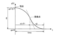
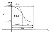
停止時単位時間変動関数g(t)は、減速停止期間timeの始期(移動量算出部22が緊急停止要求を受けた時点)において移動対象物が一定速度で移動している場合には、例えば図10に示すような曲線で表され、減速停止期間timeの始期において移動対象物が加速中である場合には、例えば図11に示すような曲線で表され、減速停止期間timeの始期において移動対象物が減速中である場合には、例えば図12に示すような曲線で表される。
The unit time variation function g (t) at the time of stop is, for example, when the moving object is moving at a constant speed at the beginning of the deceleration stop period time (when the movement
移動量算出部22は、減速停止期間time及び停止時単位時間変動関数g(t)の算出にあたって、まず、停止時単位時間変動関数g(t)の二次微分値jと、停止時単位時間変動関数g(t)の一次微分の傾きaを求める(ステップS42)。この際、前記二次微分値jは、次式(3)で求められ、前記一次微分の傾きaは、次式(4)で求められる。
In calculating the deceleration stop period time and the stop time unit variation function g (t), the movement
j=J/V・・・(3)
a=A/V・・・(4)
j = J / V (3)
a = A / V (4)
なお、Jは移動対象物の合成移動方向における許容ジャークであり、Aは移動対象物の合成移動方向における許容加速度である。これらJ及びAの値は、本実施形態のtime及びg(t)の算出プロセスのために設定されるパラメータであり、工作機械の機械特性から規定される加減速条件としての許容ジャーク及び許容加速度の半分程度の値に設定される。 J is an allowable jerk in the combined movement direction of the moving object, and A is an allowable acceleration in the combined movement direction of the moving object. These values of J and A are parameters set for the calculation process of time and g (t) of the present embodiment, and allowable jerk and allowable acceleration as acceleration / deceleration conditions defined from the machine characteristics of the machine tool. Is set to about half of the value.
次に、移動量算出部22は、停止時単位時間変動関数g(t)の基準時刻tによる一次微分値dgのt=0の点での値が0以上であるか否かを判断する(ステップS44)。ここで、移動量算出部22は、このdgの値が0以上であると判断した場合には、停止時単位時間変動関数g(t)で表される二次曲線の前半部の二次微分値j1を−jに設定する(ステップS46)一方、このdgの値が0よりも小さいと判断した場合には、前記二次微分値j1をjに設定する(ステップS48)。
Next, the movement
次に、移動量算出部22は、減速停止期間timeにおける停止時単位時間変動関数g(t)の始点に対する当該停止時単位時間変動関数g(t)の二次曲線の前半部の頂点の相対位置(t0,E0)を以下の式(5)及び(6)によって仮算出するとともに、その二次曲線の前半部の頂点から当該二次曲線の後半部の終点までの範囲における停止時単位時間変動関数g(t)の値の変化量Eを以下の式(7)によって仮算出する(ステップS50)。
Next, the movement
t0=−dg/j1・・・(5)
E0=(dg/2)×t0・・・(6)
E=ge−gs−E0・・・(7)
t0 = −dg / j1 (5)
E0 = (dg / 2) × t0 (6)
E = ge-gs-E0 (7)
次に、移動量算出部22は、前記停止時単位時間変動関数g(t)の値の変化量Eが0以上であるか否かを判断する(ステップS52)。ここで、移動量算出部22は、前記変化量Eが0以上であると判断した場合には、停止時単位時間変動関数g(t)の二次曲線の前半部の二次微分値j1をjに設定するとともに、停止時単位時間変動関数g(t)の二次曲線の後半部の二次微分値j2を−jに設定する(ステップS54)。一方、移動量算出部22は、前記変化量Eが0よりも小さいと判断した場合には、前記二次曲線の前半部の二次微分値j1を−jに設定するとともに、前記二次曲線の後半部の二次微分値j2をjに設定し、さらに、前記g(t)の一次微分の傾きaを正負逆に設定する(ステップS56)。
Next, the movement
次に、移動量算出部22は、停止時単位時間変動関数g(t)の二次曲線の始点に対する当該二次曲線の前半部の頂点の相対位置(t0,E0)を上記式(5),(6)によって再算出するとともに、その二次曲線の前半部の頂点から後半部の終点までのg(t)の変化量Eを上記式(7)によって再算出する(ステップS58)。
Next, the movement
次に、移動量算出部22は、停止時単位時間変動関数g(t)の二次曲線の前半部の頂点のg(t)の値guと、当該二次曲線の始点から変曲点までにかかる時間t1と、当該二次曲線の変曲点から終点までにかかる時間t2と、当該二次曲線の始点から変曲点までの範囲におけるg(t)の変化量G1と、当該二次曲線の変曲点から終点までの範囲におけるg(t)の変化量G2と、当該二次曲線の始点から終点までの範囲におけるg(t)の変化量Gとをそれぞれ算出する(ステップS60)。この際、移動量算出部22は、前記guを以下の式(8)によって算出し、前記t1を以下の式(9)によって算出し、前記t2を以下の式(10)によって算出する。また、移動量算出部22は、前記G1を以下の式(11)によって算出し、前記G2を以下の式(12)によって算出し、前記Gを以下の式(13)によって算出する。
Next, the movement
gu=gs+E0・・・(8)
t1=a/j1・・・(9)
t2=−a/j2・・・(10)
G1=(a/2)×t1・・・(11)
G2=(a/2)×t2・・・(12)
G=G1+G2・・・(13)
gu = gs + E0 (8)
t1 = a / j1 (9)
t2 = −a / j2 (10)
G1 = (a / 2) × t1 (11)
G2 = (a / 2) × t2 (12)
G = G1 + G2 (13)
次に、移動量算出部22は、前記二次曲線の前半部の頂点から後半部の終点までの範囲におけるg(t)の変化量の絶対値|E|が前記二次曲線の始点から終点までの範囲におけるg(t)の変化量の絶対値|G|以上であるか否かを判断する(ステップS62)。ここで、前記|E|が前記|G|以上である場合は、図13に示すように前記二次曲線の前半の曲線部と後半の曲線部との間に直線部が介在している場合に対応するため、移動量算出部22は、その前半の曲線部の区間0≦t≦T1、直線部の区間T1<t<T2及び後半の曲線部の区間T2≦t≦timeの3つの区間のそれぞれにおける停止時単位時間変動関数g(t)を個別に求める(ステップS64)。
Next, the movement
具体的には、移動量算出部22は、0≦t≦T1の区間の停止時単位時間変動関数g(t)を次式(14)で求める。
Specifically, the movement
g(t)=gu+(j1/2)×(t−t0)2・・・(14) g (t) = gu + (j1 / 2) × (t−t0) 2 (14)
また、移動量算出部22は、T1<t<T2の区間の停止時単位時間変動関数g(t)を次式(15)で求める。
Further, the movement
g(t)=gu+G1+a×(t−T1)・・・(15) g (t) = gu + G1 + a × (t−T1) (15)
また、移動量算出部22は、T2≦t≦timeの区間の停止時単位時間変動関数g(t)を次式(16)で求める。
Further, the movement
g(t)=ge+(j2/2)×(t−time)2・・・(16) g (t) = ge + (j2 / 2) × (t-time) 2 (16)
なお、この場合において、前記T1は、前記二次曲線の始点から第1の変曲点(前半の曲線部の終点)までにかかる時間であり、以下の式(17)によって求められ、前記T2は、前記二次曲線の始点から第2の変曲点(直線部の終点)までにかかる時間であり、以下の式(18)によって求められる。また、減速停止期間timeは、前記二次曲線の始点から終点までにかかる時間であるため、以下の式(19)によって求められる。 In this case, T1 is the time taken from the start point of the quadratic curve to the first inflection point (the end point of the first half of the curve), and is obtained by the following equation (17), and the T2 Is the time taken from the start point of the quadratic curve to the second inflection point (end point of the straight line portion), and is obtained by the following equation (18). In addition, the deceleration stop period time is the time taken from the start point to the end point of the quadratic curve, and is obtained by the following equation (19).
T1=t0+t1・・・(17)
T2=T1+(E−G)/a・・・(18)
time=T2+t2・・・(19)
T1 = t0 + t1 (17)
T2 = T1 + (EG) / a (18)
time = T2 + t2 (19)
一方、前記|E|が前記|G|よりも小さい場合は、前記二次曲線の前半の曲線部と後半の曲線部との間に直線部が介在せず、それら両曲線部が連続している場合に対応するため、移動量算出部22は、その前半の曲線部の区間0≦t≦T1及び後半の曲線部の区間T1<t≦timeの2つの区間のそれぞれにおける停止時単位時間変動関数g(t)を個別に求める(ステップS65)。
On the other hand, when the | E | is smaller than the | G |, there is no straight line portion between the first half curve portion and the second half curve portion of the quadratic curve, and these two curve portions are continuous. In order to cope with the case, the movement
具体的には、移動量算出部22は、0≦t≦T1の区間の停止時単位時間変動関数g(t)を次式(20)で求める。
Specifically, the movement
g(t)=gu+(j1/2)×(t−t0)2・・・(20) g (t) = gu + (j1 / 2) × (t−t0) 2 (20)
また、移動量算出部22は、T1<t≦timeの区間の停止時単位時間変動関数g(t)を次式(21)で求める。
Further, the movement
g(t)=ge+(j2/2)×(t−time)2・・・(21) g (t) = ge + (j2 / 2) × (t-time) 2 (21)
なお、この場合において、減速停止期間timeは、次式(22)によって求められる。 In this case, the deceleration stop period time is obtained by the following equation (22).
time=T1+t2・・・(22) time = T1 + t2 (22)
ここで、T1は、前記二次曲線の始点から変曲点(前半の曲線部の終点)までにかかる時間であり、次式(23)によって求められる。 Here, T1 is the time taken from the start point of the quadratic curve to the inflection point (end point of the first half curve portion), and is obtained by the following equation (23).
T1=t0+t1・・・(23) T1 = t0 + t1 (23)
また、t1は、以下の式(24)によって求められ、t2は、以下の式(25)によって求められる。 Moreover, t1 is calculated | required by the following formula | equation (24), and t2 is calculated | required by the following formula | equation (25).
t1=[2×E×j2/{j1×(j2−j1)}]1/2・・・(24)
t2=−j1/j2×t1・・・(25)
t1 = [2 × E × j2 / {j1 × (j2−j1)}] 1/2 (24)
t2 = −j1 / j2 × t1 (25)
以上のようにして、停止時単位時間変動関数g(t)と減速停止期間timeが求められる。 As described above, the stop unit time variation function g (t) and the deceleration stop period time are obtained.
次に、移動量算出部22は、基準時刻tを0に初期セットする(図6のステップS26)。
Next, the movement
その後、移動量算出部22は、基準時刻tを1だけカウントアップし(ステップS28)、続いて、この緊急停止プロセス(減速停止期間time)における設定時刻Tの単位時間である減速時設定単位時間dT2を上記のように求めた停止時単位時間変動関数g(t)に基づいて算出する(ステップS30)。この際、算出される減速時設定単位時間dT2の長さは、緊急停止要求が加減速要求監視部10から出される直前の状態、すなわち停止指令入力装置124の緊急停止ボタン124aが押される直前の状態における設定単位時間ΔTの長さから減少した長さとなる。移動量算出部22は、前記ステップS28でカウントアップした基準時刻tを停止時単位時間変動関数g(t)に代入することによって減速時設定単位時間dT2を算出する。
Thereafter, the movement
次に、移動量算出部22は、減速時設定単位時間dT2当たりの各移動軸毎の移動量dP[axis]、すなわち設定時刻TからT+dT2までの各移動軸毎の移動量dP[axis]を次式(27)によって算出する(ステップS32)。
Next, the movement
dP[axis]=path(T+dT2)[axis]−path(T)[axis]・・・(27) dP [axis] = path (T + dT2) [axis] −path (T) [axis] (27)
このように求められた減速時設定単位時間dT2当たりの各移動軸毎の移動量dP[axis]は、緊急停止要求が加減速要求監視部10から出される直前の状態における設定単位時間ΔT当たりの各移動軸毎の移動量よりも小さくなる。
The movement amount dP [axis] for each moving axis per set unit time dT2 during deceleration obtained in this way is the set amount per set unit time ΔT in the state immediately before the emergency stop request is issued from the acceleration / deceleration
その後、前記ステップS12と同様に、駆動制御部14が、移動量算出部22によって算出された減速時設定単位時間dT2当たりの各移動軸毎の移動量dP[axis]に応じて各駆動装置102c,106b,108b,110bを駆動してそれら駆動装置102c,106b,108b,110bに対応する支持体102b,106a,108a,110aを基準単位時間当たりに対応する各移動軸毎の移動量dP[axis]だけ移送させる(ステップS34)。
After that, as in step S12, the
次に、移動量算出部22は、設定時刻Tに前記ステップS30で算出した減速時設定単位時間dT2を加算して設定時刻Tを更新する(ステップS36)。
Next, the movement
その後、移動量算出部22は、基準時刻tが減速停止期間time以上になったか否かを判断する(ステップS38)。ここで、移動量算出部22が基準時刻tが減速停止期間time以上であると判断した場合には、移動対象物の移動が停止していることになり、移動量算出部22は、次に、メモリ5に記憶されている合成移動速度Vの値を読み込む(ステップS40)。この後、再始動指令入力装置126に再始動指令が入力された場合には、移動対象物の移動を再開させる再始動プロセス(図7参照)が行われる。一方、移動量算出部22は、前記ステップS38において、基準時刻tが減速停止期間timeを経過していないと判断した場合には、前記ステップS28以降の処理を再度行う。
Thereafter, the movement
次に、移動対象物の再始動プロセスについて説明する。この再始動プロセスでは、移動量算出部22が加減速要求監視部10から再始動要求が出力されているか否かを判断する(ステップS68)。ここで、移動量算出部22は、加減速要求監視部10から再始動要求が出されていないと判断した場合には、当該ステップS68の判断を繰り返し行う。一方、移動量算出部22は、加減速要求監視部10から再始動要求が出されていると判断した場合には、次に、再始動加速期間timeと再始動時単位時間変動関数g(t)を算出する(ステップS70)。この際、移動量算出部22は、再始動加速期間timeの始期における再始動時単位時間変動関数g(t)の値gsが0であり、再始動加速期間timeの終期における再始動時単位時間変動関数g(t)の値geが現時点でのオーバーライド係数kに等しくなり、再始動加速期間timeの終期における合成移動速度が前記Vとなるという条件を満たす再始動加速期間time及び再始動時単位時間変動関数g(t)を算出する。この再始動加速期間time及び再始動時単位時間変動関数g(t)の算出プロセスは、上記した減速停止期間time及び停止時単位時間変動関数g(t)の算出プロセス(図9のステップS42〜S65)と同様である。また、この算出プロセスでは、前記t0及び前記E0は共に0となり、前記dgは0である。
Next, the restart process of the moving object will be described. In this restart process, the movement
再始動時単位時間変動関数g(t)は、その関数によって表される前半の二次曲線の頂点から後半の二次曲線の終点までの区間におけるg(t)の変化量の絶対値|E|が再始動加速期間timeにおけるg(t)の変化量の絶対値|G|以上である場合には、図14に示すような前半の曲線部と後半の曲線部との間に直線部が介在するような曲線で表され、前記|E|が前記|G|よりも小さい場合には、図15に示すような前半の曲線部と後半の曲線部とが直線部を介することなく連続している曲線で表される。 The unit time variation function g (t) at the time of restart is the absolute value of the change amount of g (t) in the section from the vertex of the first-order quadratic curve to the end point of the second-order quadratic curve represented by the function | E Is equal to or greater than the absolute value | G | of the amount of change in g (t) during the restart acceleration period time, a straight line portion is present between the first half curve portion and the second half curve portion as shown in FIG. If the | E | is smaller than the | G |, the first-half curve portion and the second-half curve portion shown in FIG. 15 are continuous without passing through the straight-line portion. It is represented by a curved line.
そして、移動量算出部22は、再始動加速期間time及び再始動時単位時間変動関数g(t)を算出した後、図7のステップS72〜S84のプロセスを上記図6のステップS26〜S38のプロセスと同様に行う。この際、移動量算出部22は、ステップS76において、ステップS70で算出した再始動時単位時間変動関数g(t)に基づいて加速時設定単位時間dT2を算出し、ステップS78において、その算出した加速時設定単位時間dT2当たりの各移動軸毎の移動量dP[axis]を算出する。以上のような再始動プロセスが行われることによって、移動停止していた移動対象物は、移動を再開し、現時点でのオーバーライド係数kに応じた速度まで加速する。
Then, after calculating the restart acceleration period time and the restart time unit variation function g (t), the movement
そして、移動量算出部22がステップS84の判断において基準時刻tが再始動加速期間time以上であると判断した場合には、移動量算出部22は、図4のステップS8以降の処理を再度行う。
When the movement
ところで、移動量算出部22が前記ステップS16において加減速要求監視部10から緊急停止要求が出されていないと判断した場合には、その後、加減速要求監視部10から速度変更要求が出されているか否かを判断する(ステップS18)。
By the way, when the movement
ここで、移動量算出部22は、加減速要求監視部10から速度変更要求が出されていると判断した場合には、図8に示す移動対象物の速度変更プロセスを実施する。
Here, when it is determined that the speed change request is issued from the acceleration / deceleration
具体的には、移動量算出部22は、まず、速度変更期間timeと速度変更時単位時間変動関数g(t)を算出する(ステップS86)。この際、移動量算出部22は、速度変更期間timeの始期における速度変更時単位時間変動関数g(t)の値gsが設定単位時間ΔTに等しくなり、速度変更期間timeの終期における速度変更時単位時間変動関数g(t)の値geが速度変更後のオーバーライド係数kに等しくなり、速度変更期間timeの始期における合成移動速度が前記Vとなるという条件を満たす速度変更期間time及び速度変更時単位時間変動関数g(t)を算出する。
Specifically, the movement
なお、速度変更期間timeは、オーバーライド装置128に加速指令が入力された場合には、本発明の加速期間の概念に含まれるものであり、オーバーライド装置128に減速指令が入力された場合には、本発明の減速期間の概念に含まれるものである。また、速度変更時単位時間変動関数g(t)は、オーバーライド装置128に加速指令が入力された場合には、本発明の加速時単位時間変動関数の概念に含まれるものであり、オーバーライド装置128に減速指令が入力された場合には、本発明の減速時単位時間変動関数の概念に含まれるものである。
The speed change period time is included in the concept of the acceleration period of the present invention when the acceleration command is input to the
移動対象物の加速動作を行う場合の速度変更時単位時間変動関数g(t)は、速度変更期間timeの始期(移動量算出部22が速度変更要求を受けた時点)において移動対象物が一定速度で移動している場合には、例えば図16に示すような曲線で表される。一方、速度変更期間timeの始期において移動対象物が加速中である場合に、さらにその移動対象物の加速動作が実行される場合の速度変更時単位時間変動関数g(t)は、図17に示すような曲線で表され、速度変更期間timeの始期において移動対象物が減速中である場合にその移動対象物の加速動作が実行される場合の速度変更時単位時間変動関数g(t)は、図18に示すような曲線で表される。
The speed change unit time variation function g (t) when the moving object is accelerated is constant at the start of the speed change period time (when the movement
また、移動対象物の減速動作を行う場合の速度変更時単位時間変動関数g(t)は、速度変更期間timeの始期(移動量算出部22が速度変更要求を受けた時点)において移動対象物が一定速度で移動している場合には、例えば図19に示すような曲線で表される。一方、速度変更期間timeの始期において移動対象物が加速中である場合にその移動対象物の減速動作が実行される場合の速度変更時単位時間変動関数g(t)は、図20に示すような曲線で表され、速度変更期間timeの始期において移動対象物が減速中である場合にさらにその移動対象物の減速動作が実行される場合の速度変更時単位時間変動関数g(t)は、図21に示すような曲線で表される。
The speed change unit time variation function g (t) when the moving object is decelerating is the moving object at the beginning of the speed change period time (when the movement
なお、前記図16〜図21は、いずれも、速度変更時単位時間変動関数g(t)によって表される前半の二次曲線の頂点から後半の二次曲線の終点までの区間におけるg(t)の変化量の絶対値|E|が速度変更期間timeにおけるg(t)の変化量の絶対値|G|よりも小さい場合に対応しており、これらの場合には、速度変更時単位時間変動関数g(t)は、前半の曲線部と後半の曲線部とが直線部を介することなく連続した形状の曲線によって表される。一方、前記|E|が前記|G|以上である場合には、これら各図の前半の曲線部と後半の曲線部とが直線部を介して繋げられた形状の曲線によって速度変更時単位時間変動関数g(t)が表される。 16 to 21 are all g (t) in the section from the vertex of the first-order quadratic curve to the end point of the second-order quadratic curve represented by the unit time variation function g (t) at the time of speed change. ) In the speed change period time is smaller than the absolute value | G | in the speed change period time. In these cases, the speed change unit time The variation function g (t) is represented by a curve having a shape in which the first-half curve portion and the second-half curve portion are continuous without a straight line portion. On the other hand, when | E | is greater than or equal to | G |, the unit time at the time of speed change is determined by a curve having a shape in which the first-half curve portion and the latter-half curve portion of each figure are connected via a straight line portion. A variation function g (t) is represented.
そして、移動量算出部22は、速度変更期間time及び速度変更時単位時間変動関数g(t)を算出した後、基準時刻tを0にセットし(ステップS88)、その後、基準時刻tを1だけカウントアップする(ステップS89)。
Then, after calculating the speed change period time and the speed change unit time variation function g (t), the movement
次に、移動量算出部22は、ステップS86で算出した速度変更時単位時間変動関数g(t)に基づいて設定単位時間ΔTを算出する(ステップS90)。この設定単位時間ΔTは、前記ステップS89でカウントアップした基準時刻tを速度変更時単位時間変動関数g(t)に代入することによって求められる。
Next, the movement
次に、移動量算出部22は、この算出した設定単位時間ΔT当たりの各移動軸毎の単位時間移動量dP[axis]を前記ステップS10と同様にして算出する(ステップS91)。
Next, the movement
次に、移動量算出部22は、前記ステップS91で算出した各移動軸毎の単位時間移動量dP[axis]から現時点での移動対象物の合成移動速度Vを算出する(ステップS92)。この合成移動速度Vの算出方法は、前記ステップS11における合成移動速度Vの算出方法と同様である。
Next, the movement
その後、駆動制御部14が、前記ステップS91で算出した移動量dP[axis]に応じて前記ステップS12と同様に各駆動装置102c,106b,108b,110bを駆動する(ステップS93)。その後、移動量算出部22は、設定時刻Tに前記ステップS90で算出した設定単位時間ΔTを加算してその設定時刻Tを更新する(ステップS94)。
Thereafter, the
次に、移動量算出部22は、前記ステップS86で求めた速度変更時単位時間変動関数g(t)を基準時刻tで微分することにより前記dgを算出する(ステップS95)。
Next, the movement
その後、移動量算出部22は、基準時刻tが速度変更期間time以上であるか否かを判断し、基準時刻tが速度変更期間time以上であると判断した場合には、前記ステップS8以降の処理を再度行う一方、基準時刻tが速度変更期間timeを経過していないと判断した場合には、次に、加減速要求監視部10から緊急停止要求が出されているか否かを前記ステップS16と同様に判断する(ステップS97)。
Thereafter, the movement
ここで、移動量算出部22が加減速要求監視部10から緊急停止要求が出されていると判断した場合には、前記ステップS22〜S38の緊急停止プロセスが実施され、加減速要求監視部10から緊急停止要求が出されていないと判断した場合には、移動量算出部22は、次に、加減速要求監視部10から速度変更要求が出されているか否かを前記ステップS18と同様に判断する(ステップS98)。移動量算出部22が加減速要求監視部10から速度変更要求が出されていると判断した場合には、前記ステップS86以降の速度変更プロセスが再度実施される。一方、移動量算出部22が加減速要求監視部10から速度変更要求が出されていないと判断した場合には、前記ステップS89以降のプロセスが再度行われる。
Here, when the movement
ところで、移動量算出部22が上記ステップS18の判断において加減速要求監視部10から速度変更要求が出されていないと判断した場合には、次に、移動量算出部22は、設定時刻Tに設定単位時間ΔTを加算して設定時刻Tを更新する(ステップS20)。その後、前記ステップS10以降のプロセスが再度行われる。
By the way, when the movement
以上のようにして、本実施形態の数値制御装置2による数値制御プロセスが実施される。
As described above, the numerical control process by the
以上説明したように、本実施形態では、移送装置102,106,108,110に移動対象物の速度変化を伴うイレギュラーな動作(緊急停止、加速を伴う再始動及び移動中の移動対象物の加減速)を実施させる際、各移動軸方向に共通の設定単位時間の長さが特別指令入力装置122への特別指令の入力直前の状態における長さからその特別指令が指示する速度変化に応じた長さに変化させられるとともに、加工パスから算出されたその変化後の設定単位時間当たりの各支持体102b,106a,108a,110aの対応する移動軸方向への移動量に応じて各支持体102b,106a,108a,110aが移送される。このため、加工パスから算出された前記変化後の設定単位時間当たりの各移動軸方向への支持体102b,106a,108a,110aの移動量は、加工パスによって規定される各移動軸間の相対的な位置関係が維持された移動量となり、その移動量に応じた各支持体102b,106a,108a,110aの移送は、加工パスによって規定される各移動軸間の相対的な位置関係が維持された状態での移送となる。その結果、移送装置102,106,108,110にワーク100の加工時における移動対象物の通常の移送とは別にその移動対象物のイレギュラーな速度変化を伴う動作(緊急停止、再始動からの加速、移動中の移動対象物の加減速)を実行させる場合に、移動対象物が加工パスからずれるのを防ぐことができる。
As described above, in this embodiment, the
また、本実施形態では、前記補間後加減速によって生じる誤差を抹消するための演算を別途行う上記特許文献1の技術や前記補間前加減速演算を行う上記特許文献2の技術のように複雑な処理を特別指令入力装置122に特別指令が入力された際に行わなくても、各移動軸方向に共通の設定単位時間の長さを変化させるという単純な処理で移動対象物が加工パスからずれるのを防ぎつつその移動対象物のイレギュラーな速度変化を伴う動作を実施することができるため、特別指令入力装置122に特別指令が入力されることによって移動対象物の速度変化を伴う動作が指示されてから移送装置102,106,108,110が実際にその移動対象物の動作を実行するまでの応答性を向上することができる。具体的には、停止指令入力装置に緊急停止指令が入力されてから移送装置102,106,108,110が実際に移動対象物の移動を緊急停止させるまでの応答性を向上することができる。また、再始動指令入力装置126に再始動指令が入力されてから移送装置102,106,108,110が実際に移動対象物の移動を再開させるまでの応答性を向上することができる。また、オーバーライド装置128に速度変更指令が入力されてから移送装置102,106,108,110が実際に移動対象物の移動を加速又は減速させるまでの応答性を向上することができる。
Further, in the present embodiment, complicated techniques such as the technique of
また、本実施形態では、移送装置102,106,108,110に移動対象物の速度変化を伴うイレギュラーな動作を実施させる場合に、駆動装置102c,106b,108b,110bの駆動の基準となる基準時刻及び基準単位時間とは異なる設定時刻及び設定単位時間が設定されてその設定単位時間当たりの各支持体102b,106a,108a,110aの対応する移動軸方向への移動量が加工パスから算出されることにより、各支持体102b,106a,108a,110aを基準単位時間当たりに移動させるべき移動量が算出される。すなわち、本実施形態では、駆動装置102c,106b,108b,110bの駆動の基準となる基準時刻及び基準単位時間に影響を与えずに、移動対象物の速度変化を伴うイレギュラーな動作を実施するための各支持体102b,106a,108a,110aの基準単位時間当たりの移動量が算出される。このため、各駆動装置102c,106b,108b,110bの通常の駆動に影響を与えることなく、移動対象物のイレギュラーな速度変化を伴う動作を実施することができる。
Further, in the present embodiment, when the
なお、今回開示された実施形態は、すべての点で例示であって制限的なものではないと考えられるべきである。本発明の範囲は、上記した実施形態の説明ではなく特許請求の範囲によって示され、さらに特許請求の範囲と均等の意味及び範囲内でのすべての変更が含まれる。 The embodiment disclosed this time should be considered as illustrative in all points and not restrictive. The scope of the present invention is shown not by the above description of the embodiments but by the scope of claims for patent, and further includes meanings equivalent to the scope of claims for patent and all modifications within the scope.
例えば、本発明による数値制御装置は、上記実施形態で示したような工作機械以外の工作機械に適用してもよい。 For example, the numerical control device according to the present invention may be applied to a machine tool other than the machine tool as shown in the above embodiment.
また、移動指令パス導出部は、必ずしも補間演算部や加減速フィルタを備えてなくてもよい。すなわち、移動指令パス導出部が加工指令プログラムの加工パスから補間演算を行うことなく導出した各移動軸毎の移動指令パスに基づいて、移動量算出部が設定単位時間当たりの各支持体の対応する移動軸方向への移動量を算出してもよい。 Further, the movement command path deriving unit does not necessarily include an interpolation calculation unit and an acceleration / deceleration filter. That is, based on the movement command path for each movement axis derived by the movement command path deriving unit without performing interpolation calculation from the machining path of the machining command program, the movement amount calculation unit can handle each support per set unit time. The amount of movement in the direction of the movement axis may be calculated.
また、本発明の数値制御装置による移送装置の制御は、必ずしも、移動対象物の緊急停止時の減速、再始動時の加速及びオーバーライド装置による加減速の全てに適用されなくてもよい。例えば、移動対象物の緊急停止時の減速にのみ本発明の数値制御装置による移送装置の制御が適用されてもよく、移動対象物の再始動時の加速にのみ本発明の数値制御装置による移送装置の制御が適用されてもよく、オーバーライド装置による移動対象物の加減速にのみ本発明の数値制御装置による移送装置の制御が適用されてもよい。また、移動対象物の緊急停止時の減速、再始動時の加速及びオーバーライド装置による加減速のうちいずれか2つに対して本発明の数値制御装置による移送装置の制御が適用されてもよい。これらの場合には、停止信号入力装置、再始動信号入力装置及びオーバーライド装置のうち本発明の数値制御装置による制御が適用される移動対象物の速度変化を伴う動作を指示するための装置が、本発明の特別指令入力装置に含まれる。 Further, the control of the transfer device by the numerical control device of the present invention may not necessarily be applied to all of the deceleration at the time of emergency stop of the moving object, the acceleration at the restart, and the acceleration / deceleration by the override device. For example, the control of the transfer device by the numerical control device of the present invention may be applied only to the deceleration at the time of emergency stop of the moving object, and the transfer by the numerical control device of the present invention only to the acceleration at the restart of the moving object. The control of the device may be applied, and the control of the transfer device by the numerical control device of the present invention may be applied only to the acceleration / deceleration of the moving object by the override device. Further, the control of the transfer device by the numerical control device of the present invention may be applied to any two of the deceleration at the emergency stop of the moving object, the acceleration at the restart, and the acceleration / deceleration by the override device. In these cases, among the stop signal input device, restart signal input device and override device, a device for instructing an operation accompanied by a speed change of the moving object to which the control by the numerical control device of the present invention is applied, It is included in the special command input device of the present invention.
2 数値制御装置
4 記憶部
12 演算部
14 駆動制御部
20 移動指令パス導出部
22 移動量算出部
102 ワーク移送装置(移送装置)
102b ワーク支持体(支持体)
102c ワーク駆動装置(駆動装置)
105 工具
106 鉛直移送装置(移送装置)
106a 鉛直支持体(支持体)
106b 鉛直駆動装置(駆動装置)
108 工具第1水平移送装置(移送装置)
108a 第1水平支持体(支持体)
108b 第1水平駆動装置(駆動装置)
110 工具第2水平移送装置(移送装置)
110a 第2水平支持体(支持体)
110b 第2水平駆動装置(駆動装置)
122 特別指令入力装置
124 停止指令入力装置
126 再始動指令入力装置
128 オーバーライド装置(速度変更指令入力装置)
W ワーク
2
102b Work support (support)
102c Work drive device (drive device)
105
106a Vertical support (support)
106b Vertical drive device (drive device)
108 Tool first horizontal transfer device (transfer device)
108a First horizontal support (support)
108b First horizontal drive device (drive device)
110 Tool second horizontal transfer device (transfer device)
110a Second horizontal support (support)
110b Second horizontal drive device (drive device)
122 Special
W Work
Claims (4)
前記ワークの加工時に前記移動対象物が基準時刻の経過に伴って移動すべき経路を表す加工パスが規定された加工指令プログラムを記憶する記憶部と、
前記加工パスに基づいてある設定単位時間当たりの前記各支持体の対応する前記移動軸方向への移動量をそれぞれ算出する演算部と、
前記各駆動装置の駆動の基準となる基準単位時間毎にその各駆動装置を駆動してその各駆動装置に前記基準単位時間当たりに前記演算部によって算出された前記移動量の分、対応する前記支持体を対応する前記移動軸方向へ移送させる駆動制御部とを備え、
前記特別指令入力装置は、前記特別指令として前記移動対象物の移動を緊急に減速させて停止させるための緊急停止指令を入力するための停止指令入力装置を含み、
前記演算部は、前記設定単位時間を前記基準単位時間とは別の単位時間として設定し、前記停止指令入力装置に前記緊急停止指令が入力されたことに応じて、前記設定単位時間の長さが所定の減速停止期間に前記停止指令入力装置への前記緊急停止指令の入力直前の状態における長さから0まで減少するような停止時単位時間変動関数に基づいて前記減速停止期間における前記設定単位時間を算出するとともにその算出した設定単位時間当たりの前記各支持体の対応する前記移動軸方向への移動量を前記加工パスから算出する、数値制御装置。 A plurality of transfer devices for transferring the moving object when the workpiece or a tool for processing the workpiece is the moving object, and the normal movement of the moving object when the workpiece is processed. A special command input device for inputting a special command for instructing an operation accompanied by a speed change of the object from the outside, and each of the transfer devices supports the moving object, and the support. A numerical control device for performing numerical control of each of the transfer devices, provided in a machine tool each having a drive device for transferring the moving object by transferring the moving object in a specific movement axis direction,
A storage unit that stores a machining command program in which a machining path representing a path that the moving object should move with the passage of a reference time when machining the workpiece;
An arithmetic unit that calculates a movement amount in the moving axis direction corresponding to each support body per set unit time based on the machining path, and
The drive unit is driven for each reference unit time serving as a reference for driving the drive units, and the drive unit corresponding to the amount of movement calculated by the arithmetic unit per reference unit time corresponds to the drive unit. A drive control unit that moves the support in the direction of the corresponding movement axis ,
The special command input device includes a stop command input device for inputting an emergency stop command for urgently decelerating and stopping the movement of the moving object as the special command,
The calculation unit sets the set unit time as a unit time different from the reference unit time, and the length of the set unit time in response to the emergency stop command being input to the stop command input device. The set unit in the deceleration stop period is based on a unit time variation function at the time of stop so that is reduced from the length in the state immediately before the emergency stop command to the stop command input device to 0 during a predetermined deceleration stop period A numerical control apparatus that calculates time and calculates a movement amount of the support in the moving axis direction corresponding to the calculated set unit time from the machining path.
前記演算部は、前記停止指令入力装置に前記緊急停止指令が入力された後に前記再始動指令入力装置に前記再始動指令が入力されたことに応じて、前記設定単位時間の長さが所定の再始動加速期間に0から特定の長さまで増加するような再始動時単位時間変動関数に基づいて前記再始動加速期間における前記設定単位時間を算出し、その算出した設定単位時間当たりの前記各支持体の対応する前記移動軸方向への移動量を前記加工パスから算出する、請求項1に記載の数値制御装置。 The special command input device includes a restart command input device for inputting a restart command for resuming and accelerating the movement of the moving object that has stopped moving as the special command,
The calculation unit has a predetermined length of the set unit time in response to the restart command being input to the restart command input device after the emergency stop command is input to the stop command input device. The set unit time in the restart acceleration period is calculated based on a restart unit time variation function that increases from 0 to a specific length during the restart acceleration period, and each support per calculated set unit time is calculated. The numerical control device according to claim 1 , wherein a movement amount of the body in the corresponding movement axis direction is calculated from the machining path.
前記演算部は、前記速度変更指令入力装置に前記加速指令が入力されたことに応じて、前記設定単位時間の長さが所定の加速期間に前記速度変更指令入力装置への前記加速指令の入力直前の状態における長さから前記加速指令に含まれる前記加速率に応じた長さまで増加するような加速時単位時間変動関数に基づいて前記加速期間における前記設定単位時間を算出し、その算出した設定単位時間当たりの前記各支持体の対応する前記移動軸方向への移動量を前記加工パスから算出する一方、前記速度変更指令入力装置に前記減速指令が入力されたことに応じて、前記設定単位時間の長さが所定の減速期間に前記速度変更指令入力装置への前記減速指令の入力直前の状態における長さから前記減速指令に含まれる前記減速率に応じた長さまで減少するような減速時単位時間変動関数に基づいて前記減速期間における前記設定単位時間を算出し、その算出した設定単位時間当たりの前記各支持体の対応する前記移動軸方向への移動量を前記加工パスから算出する、請求項1又は2に記載の数値制御装置。 The special command input device decreases an acceleration command including an instruction to increase the moving speed of the moving object and information on an acceleration rate, which is an increase rate of the moving speed, or the moving speed of the moving object as the special command. Including a speed change command input device capable of inputting a deceleration command including an instruction and information on a deceleration rate that is a decrease rate of the moving speed;
In response to the acceleration command being input to the speed change command input device, the calculation unit is configured to input the acceleration command to the speed change command input device with a length of the set unit time within a predetermined acceleration period. The set unit time in the acceleration period is calculated based on the acceleration unit time variation function that increases from the length in the previous state to the length corresponding to the acceleration rate included in the acceleration command, and the calculated setting While calculating the movement amount in the direction of the corresponding movement axis of each of the supports per unit time from the machining path, the set unit according to the input of the deceleration command to the speed change command input device The length of time is reduced from a length in a state immediately before the input of the deceleration command to the speed change command input device in a predetermined deceleration period to a length corresponding to the deceleration rate included in the deceleration command. The set unit time in the deceleration period is calculated on the basis of the deceleration time unit time variation function, and the movement amount of the support in the corresponding movement axis direction per the set unit time is calculated. calculated from the path, the numerical control apparatus according to claim 1 or 2.
前記ワークの加工時に前記移動対象物が基準時刻の経過に伴って移動すべき経路を表す加工パスが規定された加工指令プログラムを記憶する記憶部と、 A storage unit that stores a machining command program in which a machining path representing a path that the moving object should move with the passage of a reference time when machining the workpiece;
前記加工パスに基づいてある設定単位時間当たりの前記各支持体の対応する前記移動軸方向への移動量をそれぞれ算出する演算部と、 An arithmetic unit that calculates a movement amount in the moving axis direction corresponding to each support body per set unit time based on the machining path, and
前記各駆動装置の駆動の基準となる基準単位時間毎にその各駆動装置を駆動してその各駆動装置に前記基準単位時間当たりに前記演算部によって算出された前記移動量の分、対応する前記支持体を対応する前記移動軸方向へ移送させる駆動制御部とを備え、 The drive unit is driven for each reference unit time serving as a reference for driving the drive units, and the drive unit corresponding to the amount of movement calculated by the arithmetic unit per reference unit time corresponds to the drive unit. A drive control unit that moves the support in the direction of the corresponding movement axis,
前記特別指令入力装置は、前記特別指令として前記移動対象物の移動速度を上昇させる指示とその移動速度の上昇率である加速率の情報を含む加速指令又は前記移動対象物の移動速度を低下させる指示とその移動速度の低下率である減速率の情報を含む減速指令を入力することが可能な速度変更指令入力装置を含み、 The special command input device decreases an acceleration command including an instruction to increase the moving speed of the moving object and information on an acceleration rate, which is an increase rate of the moving speed, or the moving speed of the moving object as the special command. Including a speed change command input device capable of inputting a deceleration command including an instruction and information on a deceleration rate that is a decrease rate of the moving speed;
前記演算部は、前記設定単位時間を前記基準単位時間とは別の単位時間として設定し、前記速度変更指令入力装置に前記加速指令が入力されたことに応じて、前記設定単位時間の長さが所定の加速期間に前記速度変更指令入力装置への前記加速指令の入力直前の状態における長さから前記加速指令に含まれる前記加速率に応じた長さまで増加するような加速時単位時間変動関数に基づいて前記加速期間における前記設定単位時間を算出するとともにその算出した設定単位時間当たりの前記各支持体の対応する前記移動軸方向への移動量を前記加工パスから算出する一方、前記速度変更指令入力装置に前記減速指令が入力されたことに応じて、前記設定単位時間の長さが所定の減速期間に前記速度変更指令入力装置への前記減速指令の入力直前の状態における長さから前記減速指令に含まれる前記減速率に応じた長さまで減少するような減速時単位時間変動関数に基づいて前記減速期間における前記設定単位時間を算出するとともにその算出した設定単位時間当たりの前記各支持体の対応する前記移動軸方向への移動量を前記加工パスから算出する、数値制御装置。 The calculation unit sets the set unit time as a unit time different from the reference unit time, and the length of the set unit time in response to the acceleration command being input to the speed change command input device. Acceleration unit time variation function such that increases from a length in a state immediately before the acceleration command is input to the speed change command input device to a length corresponding to the acceleration rate included in the acceleration command during a predetermined acceleration period The set unit time in the acceleration period is calculated based on the calculation unit, and the amount of movement of the support in the moving axis direction corresponding to the calculated set unit time is calculated from the machining path while the speed is calculated. In response to the input of the deceleration command to the change command input device, the length of the set unit time is just before the input of the deceleration command to the speed change command input device during a predetermined deceleration period. And calculating the set unit time in the deceleration period based on a unit time variation function at the time of deceleration that decreases from the length in the state to the length corresponding to the deceleration rate included in the deceleration command. A numerical control device that calculates the amount of movement of each support in the direction of the corresponding movement axis from the machining path.
Priority Applications (5)
| Application Number | Priority Date | Filing Date | Title |
|---|---|---|---|
| JP2010171050A JP5331068B2 (en) | 2010-07-29 | 2010-07-29 | Numerical controller |
| CN2011800368997A CN103140817A (en) | 2010-07-29 | 2011-07-28 | Numerical control apparatus |
| EP11812081.5A EP2600217A1 (en) | 2010-07-29 | 2011-07-28 | Numerical control apparatus |
| PCT/JP2011/004277 WO2012014479A1 (en) | 2010-07-29 | 2011-07-28 | Numerical control apparatus |
| US13/812,645 US20130123968A1 (en) | 2010-07-29 | 2011-07-28 | Numerical control apparatus |
Applications Claiming Priority (1)
| Application Number | Priority Date | Filing Date | Title |
|---|---|---|---|
| JP2010171050A JP5331068B2 (en) | 2010-07-29 | 2010-07-29 | Numerical controller |
Publications (3)
| Publication Number | Publication Date |
|---|---|
| JP2012032960A JP2012032960A (en) | 2012-02-16 |
| JP2012032960A5 JP2012032960A5 (en) | 2013-04-11 |
| JP5331068B2 true JP5331068B2 (en) | 2013-10-30 |
Family
ID=45529710
Family Applications (1)
| Application Number | Title | Priority Date | Filing Date |
|---|---|---|---|
| JP2010171050A Expired - Fee Related JP5331068B2 (en) | 2010-07-29 | 2010-07-29 | Numerical controller |
Country Status (5)
| Country | Link |
|---|---|
| US (1) | US20130123968A1 (en) |
| EP (1) | EP2600217A1 (en) |
| JP (1) | JP5331068B2 (en) |
| CN (1) | CN103140817A (en) |
| WO (1) | WO2012014479A1 (en) |
Families Citing this family (8)
| Publication number | Priority date | Publication date | Assignee | Title |
|---|---|---|---|---|
| JP5417392B2 (en) * | 2011-07-29 | 2014-02-12 | 新日本工機株式会社 | Numerical controller |
| JP5715189B2 (en) * | 2013-06-12 | 2015-05-07 | ファナック株式会社 | Numerical control device with a function to smoothly change the feed rate when the override changes |
| JP6034835B2 (en) * | 2014-08-26 | 2016-11-30 | ファナック株式会社 | Numerical control device for presenting information for shortening cycle time |
| JP6121972B2 (en) * | 2014-10-22 | 2017-04-26 | ファナック株式会社 | Numerical control device that shortens motor stop distance |
| JP6769219B2 (en) * | 2016-09-30 | 2020-10-14 | ブラザー工業株式会社 | Numerical control device |
| JP6396389B2 (en) * | 2016-10-27 | 2018-09-26 | ファナック株式会社 | Servo control device |
| JP6502976B2 (en) | 2017-02-15 | 2019-04-17 | ファナック株式会社 | Numerical control device |
| JP7135407B2 (en) * | 2018-04-26 | 2022-09-13 | セイコーエプソン株式会社 | electronic clock |
Family Cites Families (11)
| Publication number | Priority date | Publication date | Assignee | Title |
|---|---|---|---|---|
| US3557461A (en) * | 1967-04-18 | 1971-01-26 | Disk Pack Corp | Mechanical disc pack tester and method |
| JPS63273108A (en) * | 1987-04-30 | 1988-11-10 | Fanuc Ltd | Speed controller |
| JP2897333B2 (en) * | 1990-04-11 | 1999-05-31 | ブラザー工業株式会社 | Servo control device |
| JPH06110532A (en) * | 1992-09-29 | 1994-04-22 | Intetsuku:Kk | Method for controlling position and device thereof |
| JPH11202915A (en) * | 1998-01-16 | 1999-07-30 | Fanuc Ltd | Controller for automatic machine |
| JP3508677B2 (en) * | 2000-02-04 | 2004-03-22 | 三菱電機株式会社 | Robot controller |
| CN100394336C (en) * | 2002-10-30 | 2008-06-11 | 三菱电机株式会社 | Numerical control device |
| JP2006004275A (en) * | 2004-06-18 | 2006-01-05 | Fanuc Ltd | Numerical control device |
| JP4796936B2 (en) * | 2006-11-01 | 2011-10-19 | 株式会社ソディック | Processing control device |
| JP5009010B2 (en) | 2007-03-13 | 2012-08-22 | 新日本工機株式会社 | Numerical controller |
| JP5129064B2 (en) | 2008-08-26 | 2013-01-23 | 新日本工機株式会社 | Numerical control device for machine tools |
-
2010
- 2010-07-29 JP JP2010171050A patent/JP5331068B2/en not_active Expired - Fee Related
-
2011
- 2011-07-28 EP EP11812081.5A patent/EP2600217A1/en not_active Withdrawn
- 2011-07-28 CN CN2011800368997A patent/CN103140817A/en active Pending
- 2011-07-28 WO PCT/JP2011/004277 patent/WO2012014479A1/en active Application Filing
- 2011-07-28 US US13/812,645 patent/US20130123968A1/en not_active Abandoned
Also Published As
| Publication number | Publication date |
|---|---|
| CN103140817A (en) | 2013-06-05 |
| WO2012014479A1 (en) | 2012-02-02 |
| EP2600217A1 (en) | 2013-06-05 |
| US20130123968A1 (en) | 2013-05-16 |
| JP2012032960A (en) | 2012-02-16 |
Similar Documents
| Publication | Publication Date | Title |
|---|---|---|
| JP5331068B2 (en) | Numerical controller | |
| JP5417392B2 (en) | Numerical controller | |
| JP5146512B2 (en) | Control device, control system, and control method | |
| JP5506945B2 (en) | Numerical control method and numerical control device for machine tool | |
| JP5208325B1 (en) | Numerical control apparatus, machining system, and numerical control method | |
| WO2012057235A1 (en) | Numerical control method | |
| WO2011077791A1 (en) | Control parameter adjustment method and adjustment device | |
| JP5111589B2 (en) | Correction method when reversing the feed axis | |
| JP4261470B2 (en) | Control device | |
| CN102331744A (en) | Numerical controller for machine tool with function of controlling speed of arc operation | |
| JP5850996B1 (en) | Numerical control device with corner path generation function considering acceleration / deceleration after interpolation | |
| JPH10254526A (en) | Numerical controller | |
| JP4796936B2 (en) | Processing control device | |
| JP4709588B2 (en) | Thread cutting control method and apparatus | |
| JP3558508B2 (en) | Control device for NC machine tool | |
| JP5399537B2 (en) | Numerical controller | |
| JPH1039915A (en) | Numerical controller | |
| JP2021002092A (en) | Numerical controller | |
| JP4940266B2 (en) | Numerical control device and control program thereof | |
| JP2020170365A (en) | Numerical control device | |
| JP6464135B2 (en) | Numerical controller | |
| JP2004202594A (en) | Numerical control device | |
| JP4982170B2 (en) | Machining control device and machining control program | |
| JPH07210225A (en) | Numerical controller | |
| JPH09190211A (en) | System for controlling route of numerically controlled device |
Legal Events
| Date | Code | Title | Description |
|---|---|---|---|
| A521 | Request for written amendment filed |
Free format text: JAPANESE INTERMEDIATE CODE: A523 Effective date: 20130225 |
|
| A621 | Written request for application examination |
Free format text: JAPANESE INTERMEDIATE CODE: A621 Effective date: 20130225 |
|
| A871 | Explanation of circumstances concerning accelerated examination |
Free format text: JAPANESE INTERMEDIATE CODE: A871 Effective date: 20130225 |
|
| A975 | Report on accelerated examination |
Free format text: JAPANESE INTERMEDIATE CODE: A971005 Effective date: 20130418 |
|
| A131 | Notification of reasons for refusal |
Free format text: JAPANESE INTERMEDIATE CODE: A131 Effective date: 20130423 |
|
| A521 | Request for written amendment filed |
Free format text: JAPANESE INTERMEDIATE CODE: A523 Effective date: 20130621 |
|
| TRDD | Decision of grant or rejection written | ||
| A01 | Written decision to grant a patent or to grant a registration (utility model) |
Free format text: JAPANESE INTERMEDIATE CODE: A01 Effective date: 20130709 |
|
| A61 | First payment of annual fees (during grant procedure) |
Free format text: JAPANESE INTERMEDIATE CODE: A61 Effective date: 20130726 |
|
| R150 | Certificate of patent or registration of utility model |
Ref document number: 5331068 Country of ref document: JP Free format text: JAPANESE INTERMEDIATE CODE: R150 Free format text: JAPANESE INTERMEDIATE CODE: R150 |
|
| R250 | Receipt of annual fees |
Free format text: JAPANESE INTERMEDIATE CODE: R250 |
|
| R250 | Receipt of annual fees |
Free format text: JAPANESE INTERMEDIATE CODE: R250 |
|
| R250 | Receipt of annual fees |
Free format text: JAPANESE INTERMEDIATE CODE: R250 |
|
| R250 | Receipt of annual fees |
Free format text: JAPANESE INTERMEDIATE CODE: R250 |
|
| LAPS | Cancellation because of no payment of annual fees |