CN103140817A - Numerical control apparatus - Google Patents
Numerical control apparatus Download PDFInfo
- Publication number
- CN103140817A CN103140817A CN2011800368997A CN201180036899A CN103140817A CN 103140817 A CN103140817 A CN 103140817A CN 2011800368997 A CN2011800368997 A CN 2011800368997A CN 201180036899 A CN201180036899 A CN 201180036899A CN 103140817 A CN103140817 A CN 103140817A
- Authority
- CN
- China
- Prior art keywords
- unit interval
- instruction
- deceleration
- mobile object
- movement
- Prior art date
- Legal status (The legal status is an assumption and is not a legal conclusion. Google has not performed a legal analysis and makes no representation as to the accuracy of the status listed.)
- Pending
Links
- 230000033001 locomotion Effects 0.000 claims abstract description 198
- 230000008859 change Effects 0.000 claims abstract description 156
- 230000004044 response Effects 0.000 claims abstract description 29
- 238000004364 calculation method Methods 0.000 claims abstract description 26
- 230000001133 acceleration Effects 0.000 claims description 146
- 238000003754 machining Methods 0.000 claims description 76
- 238000000034 method Methods 0.000 claims description 55
- 230000009471 action Effects 0.000 claims description 47
- 230000008569 process Effects 0.000 claims description 45
- 230000004075 alteration Effects 0.000 claims description 22
- 230000033228 biological regulation Effects 0.000 claims description 12
- 238000003860 storage Methods 0.000 claims description 10
- 238000012544 monitoring process Methods 0.000 description 45
- 238000005516 engineering process Methods 0.000 description 20
- 238000006243 chemical reaction Methods 0.000 description 19
- 230000008054 signal transmission Effects 0.000 description 13
- 230000001788 irregular Effects 0.000 description 12
- 238000012508 change request Methods 0.000 description 11
- 238000010586 diagram Methods 0.000 description 8
- 230000035939 shock Effects 0.000 description 7
- NJPPVKZQTLUDBO-UHFFFAOYSA-N novaluron Chemical compound C1=C(Cl)C(OC(F)(F)C(OC(F)(F)F)F)=CC=C1NC(=O)NC(=O)C1=C(F)C=CC=C1F NJPPVKZQTLUDBO-UHFFFAOYSA-N 0.000 description 3
- 230000005540 biological transmission Effects 0.000 description 2
- 238000003825 pressing Methods 0.000 description 2
- 238000006467 substitution reaction Methods 0.000 description 2
- NAWXUBYGYWOOIX-SFHVURJKSA-N (2s)-2-[[4-[2-(2,4-diaminoquinazolin-6-yl)ethyl]benzoyl]amino]-4-methylidenepentanedioic acid Chemical compound C1=CC2=NC(N)=NC(N)=C2C=C1CCC1=CC=C(C(=O)N[C@@H](CC(=C)C(O)=O)C(O)=O)C=C1 NAWXUBYGYWOOIX-SFHVURJKSA-N 0.000 description 1
- 230000036461 convulsion Effects 0.000 description 1
- 230000007423 decrease Effects 0.000 description 1
- 230000002950 deficient Effects 0.000 description 1
- 230000014759 maintenance of location Effects 0.000 description 1
- 230000002040 relaxant effect Effects 0.000 description 1
- 230000000630 rising effect Effects 0.000 description 1
- 230000001052 transient effect Effects 0.000 description 1
Images


Classifications
-
- G—PHYSICS
- G05—CONTROLLING; REGULATING
- G05B—CONTROL OR REGULATING SYSTEMS IN GENERAL; FUNCTIONAL ELEMENTS OF SUCH SYSTEMS; MONITORING OR TESTING ARRANGEMENTS FOR SUCH SYSTEMS OR ELEMENTS
- G05B19/00—Programme-control systems
- G05B19/02—Programme-control systems electric
- G05B19/18—Numerical control [NC], i.e. automatically operating machines, in particular machine tools, e.g. in a manufacturing environment, so as to execute positioning, movement or co-ordinated operations by means of programme data in numerical form
- G05B19/402—Numerical control [NC], i.e. automatically operating machines, in particular machine tools, e.g. in a manufacturing environment, so as to execute positioning, movement or co-ordinated operations by means of programme data in numerical form characterised by control arrangements for positioning, e.g. centring a tool relative to a hole in the workpiece, additional detection means to correct position
-
- G—PHYSICS
- G05—CONTROLLING; REGULATING
- G05B—CONTROL OR REGULATING SYSTEMS IN GENERAL; FUNCTIONAL ELEMENTS OF SUCH SYSTEMS; MONITORING OR TESTING ARRANGEMENTS FOR SUCH SYSTEMS OR ELEMENTS
- G05B19/00—Programme-control systems
- G05B19/02—Programme-control systems electric
- G05B19/18—Numerical control [NC], i.e. automatically operating machines, in particular machine tools, e.g. in a manufacturing environment, so as to execute positioning, movement or co-ordinated operations by means of programme data in numerical form
- G05B19/416—Numerical control [NC], i.e. automatically operating machines, in particular machine tools, e.g. in a manufacturing environment, so as to execute positioning, movement or co-ordinated operations by means of programme data in numerical form characterised by control of velocity, acceleration or deceleration
-
- G—PHYSICS
- G05—CONTROLLING; REGULATING
- G05B—CONTROL OR REGULATING SYSTEMS IN GENERAL; FUNCTIONAL ELEMENTS OF SUCH SYSTEMS; MONITORING OR TESTING ARRANGEMENTS FOR SUCH SYSTEMS OR ELEMENTS
- G05B2219/00—Program-control systems
- G05B2219/30—Nc systems
- G05B2219/43—Speed, acceleration, deceleration control ADC
- G05B2219/43062—Maximum acceleration, limit
-
- G—PHYSICS
- G05—CONTROLLING; REGULATING
- G05B—CONTROL OR REGULATING SYSTEMS IN GENERAL; FUNCTIONAL ELEMENTS OF SUCH SYSTEMS; MONITORING OR TESTING ARRANGEMENTS FOR SUCH SYSTEMS OR ELEMENTS
- G05B2219/00—Program-control systems
- G05B2219/30—Nc systems
- G05B2219/43—Speed, acceleration, deceleration control ADC
- G05B2219/43065—Limitation of jerk
-
- G—PHYSICS
- G05—CONTROLLING; REGULATING
- G05B—CONTROL OR REGULATING SYSTEMS IN GENERAL; FUNCTIONAL ELEMENTS OF SUCH SYSTEMS; MONITORING OR TESTING ARRANGEMENTS FOR SUCH SYSTEMS OR ELEMENTS
- G05B2219/00—Program-control systems
- G05B2219/30—Nc systems
- G05B2219/43—Speed, acceleration, deceleration control ADC
- G05B2219/43102—Time constant acceleration, deceleration as function of machining conditions
-
- G—PHYSICS
- G05—CONTROLLING; REGULATING
- G05B—CONTROL OR REGULATING SYSTEMS IN GENERAL; FUNCTIONAL ELEMENTS OF SUCH SYSTEMS; MONITORING OR TESTING ARRANGEMENTS FOR SUCH SYSTEMS OR ELEMENTS
- G05B2219/00—Program-control systems
- G05B2219/30—Nc systems
- G05B2219/43—Speed, acceleration, deceleration control ADC
- G05B2219/43158—Feedrate override
-
- G—PHYSICS
- G05—CONTROLLING; REGULATING
- G05B—CONTROL OR REGULATING SYSTEMS IN GENERAL; FUNCTIONAL ELEMENTS OF SUCH SYSTEMS; MONITORING OR TESTING ARRANGEMENTS FOR SUCH SYSTEMS OR ELEMENTS
- G05B2219/00—Program-control systems
- G05B2219/30—Nc systems
- G05B2219/43—Speed, acceleration, deceleration control ADC
- G05B2219/43172—Change velocities on the fly during a motion
-
- G—PHYSICS
- G05—CONTROLLING; REGULATING
- G05B—CONTROL OR REGULATING SYSTEMS IN GENERAL; FUNCTIONAL ELEMENTS OF SUCH SYSTEMS; MONITORING OR TESTING ARRANGEMENTS FOR SUCH SYSTEMS OR ELEMENTS
- G05B2219/00—Program-control systems
- G05B2219/30—Nc systems
- G05B2219/50—Machine tool, machine tool null till machine tool work handling
- G05B2219/50103—Restart, reverse, return along machined path, stop
-
- G—PHYSICS
- G05—CONTROLLING; REGULATING
- G05B—CONTROL OR REGULATING SYSTEMS IN GENERAL; FUNCTIONAL ELEMENTS OF SUCH SYSTEMS; MONITORING OR TESTING ARRANGEMENTS FOR SUCH SYSTEMS OR ELEMENTS
- G05B2219/00—Program-control systems
- G05B2219/30—Nc systems
- G05B2219/50—Machine tool, machine tool null till machine tool work handling
- G05B2219/50198—Emergency stop
Abstract
Disclosed is a numerical control apparatus which comprises: a special command input device for inputting, from outside, a special command for instructing an operation involving a velocity change of a moving target object separate from normal transfer of the moving target object during processing of a workpiece; a calculation unit for calculating, on the basis of a processing path, the amount of movement in the movement axis direction of supports per set unit time; and a driving control unit for transferring corresponding supports to drive devices in accordance with the amount of movement of the supports calculated by the calculation unit. In response to the special command being input in the special command input device, the calculation unit changes the length of the set unit time from the length immediately prior to the input of the special command to a length corresponding to the velocity change of the moving target object instructed by the special command, and calculates from the processing path the amount of movement in the movement axis direction of the supports per set unit time after the length has been changed.
Description
Technical field
The present invention relates to a kind of numerical control device.
Background technology
In various lathes in the past, according to processing instruction repertorie (NC program), conveying workpieces or the conveying device of processing the cutter of this workpiece are carried out Numerical Control, carry out thus workpiece processing.In this lathe, operated by rotary motion has can indicate by manual operation the indicating device of the action of the acceleration and deceleration of following workpiece, cutter.Waited by operator and indicate by this indicating device, can implement according to outside the common movement of the workpiece of described processing instruction repertorie or cutter, action that follow the acceleration and deceleration of workpiece or cutter.
Specifically, in lathe, as described indicating device be provided with emergency braking device, restart device, actuation means (override device) etc.Emergency braking device is used for workpiece or cutter when this mobile object thing is transferred by conveying device, indicating the emergent stopping of the conveying of this mobile object thing as the mobile object thing.This emergency braking device possesses emergency stop push button, by pressing this emergency stop push button, indicates the conveying that makes its emergent stopping mobile object thing to conveying device.In addition, restart device and be used to indicate restarting of mobile object thing after emergent stopping.This restarts device and possesses the button of restarting, and restarts button by pressing this, restarts the conveying of mobile object thing to the conveying device indication.In addition, actuation means possesses the index dial of controlling, and controls index dial by operating this, indicates the acceleration and deceleration of the transporting velocity of the mobile object thing corresponding with the operational ton of controlling index dial to conveying device.In the situation that described emergent stopping, can follow the abrupt deceleration of mobile object thing, in the situation that described restarting, can follow the sharply acceleration of mobile object thing, in addition, when by described actuation means indication acceleration and deceleration, compare during with common mobile object thing mobile, carry out acceleration and deceleration sharply.
When carrying out the action of the acceleration and deceleration of following the mobile object thing as above in lathe, can apply physical shock to lathe.Just proposed for reducing resulting from the technology of physical shock of sharply acceleration and deceleration of mobile object thing in the past.As an example of this technology, the technology of utilizing the interpolation speed controlling after interpolating that the acceleration and deceleration wave filter carries out is arranged.This interpolation speed controlling after interpolating is following technology: utilize the acceleration and deceleration wave filter, make by interpolation arithmetic to postpone the time corresponding with the instruction time constant of regulation from processing the resulting move of instruction repertorie, relax thus the indicated acceleration and deceleration sharply of processing instruction repertorie and pass through the indicated acceleration and deceleration sharply of indicating device.
But, in this interpolation speed controlling after interpolating technology, although have advantages of to relax and result from the physical shock of sharply acceleration and deceleration of mobile object thing to have but then the shortcoming of the error of the machining shape that produces workpiece.Specifically, this is effective aspect two relaxing the indicated acceleration and deceleration sharply of the indicated acceleration and deceleration sharply of processing instruction repertorie and described indicating device for this interpolation speed controlling after interpolating technology, but in the situation that this interpolation speed controlling after interpolating technology is applicable to relax the indicated acceleration and deceleration sharply of processing instruction repertorie, the actual machining shape machining shape (machining path) indicated with respect to the processing instruction repertorie produces error.In addition, in the situation that this interpolation speed controlling after interpolating technology is applicable to relax the acceleration and deceleration sharply of indicating device indication, because the machining path that relaxes by described interpolation speed controlling after interpolating technology after the indicated acceleration and deceleration sharply of processing instruction repertorie produces further error with respect to original machining path, therefore become workpiece with the reason of unexpected defective.
For problem points as above, following technology has been proposed in following patent documentation 1: in order to proofread and correct the error of the machining shape that produces by the interpolation speed controlling after interpolating, carry out for the computing of eliminating the phase error that produces between each shifting axle of mobile object thing.
In addition, proposed not use fully the acceleration and deceleration technology of interpolation speed controlling after interpolating in following patent documentation 2.In this acceleration and deceleration technology, carry out interpolation before the mobile pulse on each shifting axle that calculates the mobile object thing according to the processing instruction repertorie before the acceleration and deceleration computing, calculate in advance thus the machining path that has relaxed the indicated acceleration and deceleration sharply of processing instruction repertorie.Therefore, can obtain in advance the machining path that does not produce physical shock, can the mobile object thing be moved according to this machining path.Therefore, according to this acceleration and deceleration technology, can not produce the error that results from the interpolation speed controlling after interpolating as above, can reduce resulting from the physical shock of acceleration and deceleration sharply of mobile object thing.
But, in any technology put down in writing in described patent documentation 1 and patent documentation 2, want to relax the acceleration and deceleration sharply by described indicating device indication, become complicated according to the computing of recomputating from the indication of this indicating device.Therefore, there are the following problems: follow the action of the acceleration and deceleration of mobile object thing to play bad response till the actual action of carrying out this indicated mobile object thing by the indication of described indicating device.
specifically, carry out emergent stopping as above in lathe, follow the acceleration of restarting, when following the action of the acceleration and deceleration that utilize acceleration and deceleration that actuation means carries out etc., requirement is from carrying out the indication (emergency stop push button of this action of following acceleration and deceleration, restart the connection of button or control the operation of index dial) rise promptly, and the motion track of actual mobile object thing does not depart to be carried out this in the situation of predetermined machining path and follows the action of acceleration and deceleration, but in any technology that described patent documentation 1 and described patent documentation 2 are put down in writing, because the computing of move is all complicated, so its computing spended time, its result, implement the bad response till these acceleration and deceleration are moved to reality from the indication of carrying out the acceleration and deceleration action.
Patent documentation 1: No. 2010-55161, Japanese Patent Publication communique JP
Patent documentation 2: No. 2008-225825, Japanese Patent Publication communique JP.
Summary of the invention
The object of the invention is to address the above problem.
Namely, the object of the present invention is to provide a kind of numerical control device, in the situation that action outside the common conveying of the mobile object thing when implementing processing work in lathe, that follow the velocity variations of this mobile object thing, the motion track that can prevent the mobile object thing departs from the machining path of processing instruction repertorie indication, and can improve indication and follow the action of the velocity variations of mobile object thing to play response till this action executing.
the numerical control device that an aspect of of the present present invention is related is arranged at lathe, and described lathe possesses: a plurality of conveying devices, workpiece or the cutter of processing this workpiece as the mobile object thing, are carried described mobile object thing when the described workpiece of processing, and special instruction input media, be used for from outside input special instruction, this special instruction is used to indicate the action of the velocity variations of following this mobile object thing of the common conveying that is different from described mobile object thing when the described workpiece of processing, wherein, described each conveying device has respectively: the supporting mass that supports described mobile object thing, and by thereby this supporting mass is carried the drive unit of described mobile object thing along specific shifting axle direction, described numerical control device carries out the Numerical Control to described each conveying device, comprise: storage part, store predetermined the processing instruction repertorie of machining path, this machining path be illustrated in processing during described workpiece described mobile object thing follow benchmark constantly process and the path that should move, operational part based on described machining path, calculates respectively the amount of movement of described each supporting mass on the described shifting axle direction of correspondence in each a certain setting unit interval, and drive control part, amount of movement according to described each supporting mass that is calculated by described operational part, make described each drive unit carry the described supporting mass corresponding with this drive unit, wherein, described operational part, response is input to the described special instruction of described special instruction input media, the length that makes the described setting unit interval is the length corresponding with the velocity variations of the indicated described mobile object thing of this special instruction from the length variations of inputting under the state before this special instruction, and the amount of movement of described each supporting mass on the described shifting axle direction of correspondence in the setting unit interval after calculating each and change its length based on described machining path.
Description of drawings
Fig. 1 is the summary side elevation of lathe of the numerical control device of applicable one embodiment of the present invention.
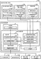
Fig. 2 is the functional block diagram of the numerical control device of one embodiment of the present invention.
Fig. 3 is the functional block diagram of move path leading-out portion and storer.
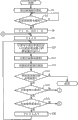
Fig. 4 means the process flow diagram of the Numerical Control process that the numerical control device of one embodiment of the present invention carries out.
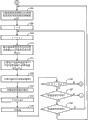
Fig. 5 means the process flow diagram of the monitoring process of the special instruction that acceleration and deceleration request monitoring unit is carried out.
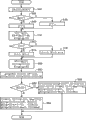
Fig. 6 means the process flow diagram of the emergent stopping process of mobile object thing.
Fig. 7 means the process flow diagram of the restart procedure of mobile object thing.
Fig. 8 means the process flow diagram of the speed change process of mobile object thing.
Fig. 9 be illustrate expression follow the action of acceleration and deceleration required during unit interval of time and the change of the unit interval in during this period change the process flow diagram of the computation process of function g (t).
The figure of unit interval change function when Figure 10 means stopping when carrying out the emergent stopping process of the mobile object thing that moves with constant speed.
The figure of unit interval change function when Figure 11 means in the acceleration of mobile object thing stopping when carrying out the emergent stopping process.
The figure of unit interval change function when Figure 12 means in the deceleration of mobile object thing stopping when carrying out the emergent stopping process.
Figure 13 be for explanation by Three regions consist of stop the time unit interval change function figure.
Figure 14 mean when carrying out the restart procedure of mobile object thing by Three regions consist of restart the time unit interval change function figure.
Figure 15 mean when carrying out the restart procedure of mobile object thing by two intervals consist of restart the time unit interval change function figure.
Figure 16 means the figure of unit interval change function when the speed when carrying out the accelerator of the mobile object thing that moves with constant speed changes.
The figure of unit interval change function when the speed when Figure 17 means the accelerator of further carrying out this mobile object thing in the acceleration of mobile object thing changes.
Figure 18 means the figure of unit interval change function when the speed when carrying out accelerator in the deceleration of mobile object thing changes.
Figure 19 means the figure of unit interval change function when the speed when carrying out the moderating process of the mobile object thing that moves with constant speed changes.
Figure 20 means the figure of unit interval change function when the speed when carrying out moderating process in the acceleration of mobile object thing changes.
The figure of unit interval change function when the speed when Figure 21 means the moderating process of further carrying out this mobile object thing in the deceleration of mobile object thing changes.
Embodiment
Below, illustrate referring to the drawings embodiments of the present invention.
At first, the see figures.1.and.2 structure of lathe of numerical control device 2 of the applicable one embodiment of the present invention of explanation.
The lathe that is provided with the numerical control device 2 (with reference to Fig. 2) of present embodiment is used for the workpiece 100 as machined object is carried out cut.This lathe possesses Work transfer device 102, column 104, cutter 105, cutter vertical conveying device 106, cutter the first horizontal feed device 108, cutter the second horizontal feed device 110, main spindle box (spindle head) 112 and console panel 114.In addition, Work transfer device 102, cutter vertical conveying device 106, cutter the first horizontal feed device 108 and cutter the second horizontal feed device 110 are included in respectively in the concept of conveying device of the present invention.
Cutter vertical conveying device 106 is arranged at column 104.This cutter vertical conveying device 106 is for the device that will carry along the Y direction of extending in vertical direction for the cutter 105 that workpiece 100 is carried out cut.This cutter vertical conveying device 106 has: can be installed on along the mode that Y direction moves the vertical support body 106a of column 104; And be arranged at column 104, and carry the vertical drive 106b (with reference to Fig. 2) of vertical support body 106a along column 104 on Y direction.Vertical support body 106a supporting cutter the first horizontal feed device 108.This cutter first horizontal feed device 108 is as described later by cutter the second horizontal feed device 110 and main spindle box 112 supporting cutters 105, so vertical support body 106a supports cutter 105 indirectly.Vertical drive 106b has the servo motor as drive source.In addition, described Y direction is included in the concept of shifting axle of the present invention.In addition, vertical support body 106a is included in the concept of supporting mass of the present invention.In addition, vertical drive 106b is included in the concept of drive unit of the present invention.
Cutter the first horizontal feed device 108 is arranged at vertical support body 106a.This cutter first horizontal feed device 108 be for cutter 105 along the device of carrying with respect to described X-axis and the two W direction of principal axis that vertically extends of described Y-axis.This cutter first horizontal feed device 108 has: can be arranged at movably along the W direction of principal axis the first horizontal supporting body 108a of vertical support body 106a; And be arranged at vertical support body 106a, with the first horizontal drive apparatus 108b (with reference to Fig. 2) of the first horizontal supporting body 108a along the ground conveying of W direction of principal axis advance and retreat.First horizontal supporting body 108a supporting cutter the second horizontal feed device 110.By main spindle box 112 supporting cutters 105, therefore the first horizontal supporting body 108a supports cutter 105 to this cutter second horizontal feed device 110 indirectly as described later.The first horizontal drive apparatus 108b has the servo motor as drive source.In addition, described W axle is included in the concept of shifting axle of the present invention.In addition, the first horizontal supporting body 108a is included in the concept of supporting mass of the present invention.In addition, the first horizontal drive apparatus 108b is included in the concept of drive unit of the present invention.
Cutter the second horizontal feed device 110 is arranged at the first horizontal supporting body 108a.This cutter second horizontal feed device 110 is devices of carrying along the Z-direction parallel with described W axle for cutter 105.This cutter second horizontal feed device 110 has: can be arranged at movably along Z-direction the second horizontal supporting body 110a of the first horizontal supporting body 108a; And be arranged at the first horizontal supporting body 108a, with the second horizontal drive apparatus 110b of the second horizontal supporting body 110a along the ground conveying of Z-direction advance and retreat.The second horizontal supporting body 110a supporting spindle case 112.This second horizontal supporting body 110a is by main spindle box 112 supporting cutters 105.The second horizontal drive apparatus 110b has the servo motor as drive source.In addition, described Z axis is included in the concept of shifting axle of the present invention.In addition, the second horizontal supporting body 110a is included in the concept of supporting mass of the present invention.In addition, the second horizontal drive apparatus 110b is included in the concept of drive unit of the present invention.
In addition, console panel 114 possesses special instruction input media 122 (with reference to Fig. 2).This special instruction input media 122 is for the device from outside input special instruction, workpiece 100 outside the workpiece 100 when this special instruction is used to indicate processing work 100 and the common conveying of cutter 105, that follow acceleration or deceleration and the action of cutter 105.In addition, the object of below, conveying device 102,106,108,110 being carried, be that workpiece 100 or cutter 105 are called the mobile object thing.
Special instruction input media 122 comprises halt instruction input media 124, restart indication input media 126 and actuation means (override device) 128.
Halt instruction input media 124 is for the device of inputting the emergent stopping instruction that is used for making urgent deceleration of movement of mobile object thing and stops.Described emergent stopping instruction is included in the concept of special instruction of the present invention.This halt instruction input media 124 has: the emergency stop push button 124a that is arranged at the outside surface of console panel 114; And respond this emergency stop push button 124a and be pressed, send the stop signal sending part 124b of washouts to acceleration and deceleration request monitoring unit 10 described later.In addition, in the present embodiment, press the input that emergency stop push button 124a is equivalent to the emergent stopping instruction.
Restart indication input media 126 is for the device of inputting the restart indication that is used for the movement of moving the mobile object thing that stops is restarted and accelerates.Described restart indication is included in the concept of special instruction of the present invention.This restart indication input media 126 has: be arranged at console panel 114 outside surface restart button 126a; And respond this and restart button 126a and be pressed, to acceleration and deceleration request monitoring unit 10 described later send restart signal restart signal transmission unit 126b.In addition, in the present embodiment, press and restart the input that button 126a is equivalent to restart indication.
Actuation means 128 is the devices for input assisted instruction or deceleration instruction.This assisted instruction comprises indication that the translational speed that makes the mobile object thing rises and as the information of the rate of acceleration of the escalating rate of this translational speed.In addition, deceleration instruction comprises indication that the translational speed that makes the mobile object thing descends and as the information of the rate of deceleration of the rate of descent of this translational speed.This actuation means 128 is included in the concept of speed alteration command input media of the present invention.In addition, described assisted instruction and described deceleration instruction are included in the concept of special instruction of the present invention.
Actuation means 128 has: be arranged at console panel 114 outside surface control index dial (override dial) 128a; And send with this speed of controlling the direction of operating of index dial 128a and the corresponding speed change signal of operational ton to acceleration and deceleration request monitoring unit described later 10 and change signal transmission unit 128b.
The operating portion that operates when controlling index dial 128a and being the input assisted instructions such as operator or deceleration instruction.Control index dial 128a being arranged at console panel 114 around the mode that its axle rotates.Control index dial 128a around a direction rotation of its axle by making, can be to actuation means 128 input assisted instruction or deceleration instructions.In the present embodiment, make control index dial 128a wherein the side operation of rotating be equivalent to the input of assisted instruction, making and controlling index dial 128a is the input that operation that opposite side rotates is equivalent to deceleration instruction to a side opposite with a described wherein side.In addition, control index dial 128a corresponding with the rate of acceleration of mobile object thing to the amount of spin of a described wherein side, control index dial 128a corresponding with the rate of deceleration of mobile object thing to the amount of spin of described opposite side.
Speed change signal transmission unit 128b response is controlled index dial 128a and is rotated to a described wherein side (acceleration side), send to acceleration and deceleration request monitoring unit 10 and comprise and control index dial 128a to this speed change signal of the corresponding information of controlling coefficient of the amount of spin of a side wherein, and, response is controlled index dial 128a and is rotated to described opposite side (deceleration side), sends to acceleration and deceleration request monitoring unit 10 comprise and control the speed change signal of index dial 128a to the corresponding information of controlling coefficient of the amount of spin of this opposite side.With control index dial 128a to corresponding the controlling in the concept that coefficient is included in rate of acceleration of the present invention of the amount of spin of a described wherein side, and control index dial 128a to corresponding the controlling in the concept that coefficient is included in the rate of deceleration of the present invention of the amount of spin of described opposite side.Control coefficient take 1 as benchmark.And, according to controlling the situation of index dial 128a to the acceleration side rotation, control coefficient from 1 increase, according to controlling the situation of index dial 128a to the deceleration side rotation, control coefficient and reduce from 1.
The numerical control device 2 of present embodiment is assembled in console panel 114, carries out described each conveying device 102,106,108,110 Numerical Control.Then, describe the structure of the numerical control device 2 of present embodiment in detail with reference to Fig. 1~Fig. 3.
As shown in Figure 2, numerical control device 2 has storage part 4, storer 5 and arithmetic processing apparatus 6.
Storage part 4 storages are as the NC program of processing instruction repertorie.This NC procedure stipulation machining path, when this machining path is illustrated in processing work 100, the mobile object thing follow benchmark constantly process and the path that should move.Correlationship between benchmark moment when machining path represents processing work 100 and the position of mobile object thing.
Each driving of setting computing, each drive unit 102c, 106b, 108b, the 110b of the amount of movement of each supporting mass 102b in unit interval, 106a, 108a, 110a that arithmetic processing apparatus 6 carries out the machining path that comprises based on the NC program that is stored in storage part 4 controls, to the various processing of the supervision of the input of the special instruction of special instruction input media 122 etc.This arithmetic processing apparatus 6 has acceleration and deceleration request monitoring unit 10, operational part 12 and drive control part 14.
Acceleration and deceleration request monitoring unit 10 monitors whether inputted described special instruction to special instruction input media 122.
Specifically, whether acceleration and deceleration request monitoring unit 10 is by detecting the washout that sends from stop signal sending part 124b, monitor to halt instruction input media 124 to have inputted deceleration stop command, be whether the emergency stop push button 124a of halt instruction input media 124 is pressed.In detail, acceleration and deceleration request monitoring unit 10 is in the situation that sent washout from stop signal sending part 124b, being judged as emergency stop push button 124a is pressed, in the situation that do not send washout from stop signal sending part 124b, be judged as emergency stop push button 124a and be not pressed.Then, 10 responses of acceleration and deceleration request monitoring unit are input to the deceleration stop command of halt instruction input media 124, namely respond the washout that sends from stop signal sending part 124b, to the amount of movement calculating part described later 22 output emergency stop request of operational part 12.
In addition, whether acceleration and deceleration request monitoring unit 10 is by detecting from restarting the signal that restarts that signal transmission unit 126b sends, monitor to restart indication input media 126 to have inputted restart indication, be restarting button 126a and whether being pressed of restart indication input media 126.In detail, acceleration and deceleration request monitoring unit 10 is in the situation that sent and restarted signal from restarting signal transmission unit 126b, be judged as and restart button 126a and be pressed, in the situation that send and not restart signal from restarting signal transmission unit 126b, be judged as and restart button 126a and be not pressed.Then, acceleration and deceleration request monitoring unit 10 response exports to amount of movement calculating part 22 described later the request of restarting being input to the restart indication of restart indication input media 126 after the 124 input emergent stopping instructions of halt instruction input media, namely responding after stop signal sending part 124b sends washout from restarting the signal that restarts of signal transmission unit 126b transmission.
Whether whether in addition, acceleration and deceleration request monitoring unit 10 is by detecting the speed change signal that sends from speed change signal transmission unit 128b, monitor to actuation means 128 to have inputted assisted instruction or deceleration instruction, namely controlled index dial 128a and be rotated.In detail, acceleration and deceleration request monitoring unit 10 is in the situation that sent speed change signal from speed change signal transmission unit 128b, be judged as and control index dial 128a and be rotated, in the situation that from speed change signal transmission unit 128b transmission speed change signal, be judged as and control index dial 128a and be not rotated.Then, the speed change signal that 10 responses of acceleration and deceleration request monitoring unit send from speed change signal transmission unit 128b comprises the speed change request of controlling coefficient information contained in this speed change signal to amount of movement calculating part 22 outputs described later.
Operational part 12 is based on the machining path that is stored in the NC program in storage part 4, calculate respectively with to the input of the special instruction of described special instruction input media 122 have or not and the kind of special instruction is corresponding, described each supporting mass 102b, 106a, 108a, the amount of movement of 110a on corresponding shifting axle direction (X-direction, Y direction, W direction of principal axis, Z-direction) in each setting unit interval.
Specifically, in the situation that not to special instruction input media 122 input special instructions, operational part 12 calculates respectively each supporting mass 102b, 106a, 108a, the amount of movement of 110a on the shifting axle direction of correspondence in each a certain setting unit interval based on described machining path.In addition, in the situation that inputted special instruction to special instruction input media 122, operational part 12 correspondingly make therewith the length of setting the unit interval from the length variations under the state before these special instruction input media 122 input special instructions for the corresponding length of velocity variations of the indicated mobile object thing of this special instruction, and each supporting mass 102b, 106a, 108a, the amount of movement of 110a on the shifting axle direction of correspondence in the setting unit interval after calculating each and change its length based on described machining path.
In detail, in the situation that inputted the emergent stopping instruction to halt instruction input media 124, operational part 12 therewith correspondingly when stopping unit interval change function calculation go out to slow down setting unit interval in stopping period, and calculate each supporting mass 102b, 106a, 108a, the amount of movement of 110a on the shifting axle direction of correspondence in each this setting unit interval that calculates based on described machining path.In addition, described deceleration stopping period be speed-down action for the emergent stopping of mobile object thing begun to the mobile object thing is actual stop till the required time.In addition, during described stopping unit interval change function mean as the length of setting the unit interval (setting the unit interval during deceleration) as described in be reduced to the function of the length change of setting unit interval of 0 in the deceleration stopping period from the length under the state before the 124 input emergent stopping instructions of halt instruction input media.
In addition, in the situation that inputted restart indication to restart indication input media 126 after the 124 input emergent stopping instructions of halt instruction input media, the setting unit interval of operational part 12 in during correspondingly unit interval change function calculation goes out to restart when restarting therewith, and calculate each supporting mass 102b, 106a, 108a, the amount of movement of 110a on the shifting axle direction of correspondence in each this setting unit interval that calculates based on described machining path.It is in addition, described that to restart the accelerating period be to stop mobile restarting of mobile object thing to have begun to accelerate to and the required time of the corresponding translational speed of coefficient of controlling that is set at this time point to the mobile object thing.In addition, during described restarting unit interval change function mean as the length of setting the unit interval (setting the unit interval during acceleration) as described in restart in the accelerating period from 0 and increase to the function of length change that restarts the setting unit interval of controlling the corresponding length of coefficient of time point with this.
In addition, in the situation that inputted assisted instruction to actuation means 128, operational part 12 therewith correspondingly when accelerating unit interval change function calculation go out setting unit interval in the accelerating period, and calculate each supporting mass 102b, 106a, 108a, the amount of movement of 110a on the shifting axle direction of correspondence in each this setting unit interval that calculates based on described machining path.In addition, the described accelerating period is that acceleration with the corresponding mobile object thing of described assisted instruction has begun to accelerate to the corresponding required time of translational speed of the described rate of acceleration (controlling coefficient) that comprises with described assisted instruction to the mobile object thing.In addition, during described accelerate unit interval change function mean as the length of setting the unit interval (setting the unit interval during acceleration) as described in the accelerating period from the length under the state before actuation means 128 input assisted instructions increase to as described in assisted instruction comprise as described in the function of length change of setting unit interval of the corresponding length of rate of acceleration.
In addition, in the situation that inputted deceleration instruction to actuation means 128, the setting unit interval of operational part 12 in correspondingly unit interval change function calculation goes out between deceleration period when slowing down therewith, and calculate each supporting mass 102b, 106a, 108a, the amount of movement of 110a on the shifting axle direction of correspondence in each this setting unit interval that calculates based on described machining path.In addition, be that deceleration with the corresponding mobile object thing of described deceleration instruction has begun to be decelerated to the corresponding required time of translational speed of the described rate of deceleration (controlling coefficient) that comprises with described deceleration instruction to the mobile object thing between described deceleration period.In addition, during described slow down unit interval change function mean as the length of setting the unit interval (setting the unit interval during deceleration) as described between deceleration period in from the length under the state before actuation means 128 input deceleration instructions be reduced to as described in deceleration instruction comprise as described in the function that changes of the length of setting unit interval of the corresponding length of the rate of deceleration.
In addition, operational part 12 is set as with described each setting-up time the unit interval that is different from as base's time of the benchmark of the driving of each drive unit 102c, 106b, 108b, 110b, and calculates the amount of movement of described each supporting mass 102b in each this setting unit interval, 106a, 108a, 110a.
And this operational part 12 has move path leading-out portion 20 and amount of movement calculating part 22.
Move path leading-out portion 20 is obtained move path path (T) on each shifting axle based on described machining path.This move path path (T) expression position that each supporting mass 102b, 106a, 108a, 110a should move on the shifting axle direction of correspondence along with the process of setting moment T.In addition, setting constantly, T is different from described benchmark constantly and the moment of setting.
As shown in Figure 3, move path leading-out portion 20 has program reading part 24, surface interpolation section 26, move path operational part 28, acceleration and deceleration operational part 30 and local acceleration and deceleration wave filter 32.
The NC program of program reading part 24 from be stored in storage part 4 reads machining path (cutter path).The machining path that is read by this program reading part 24 is stored in storer 5.
The move path that move path operational part 28 calculates the mobile composition of conduct on each shifting axle direction based on the machining path that is stored in storer 5.Move path on each shifting axle direction of this that calculates is stored in storer 5.
Acceleration and deceleration operational part 30 is for the move path on each shifting axle that is stored in storer 5, carry out according to the acceleration and deceleration condition on each shifting axle, be on each shifting axle allowable acceleration, allow that suddenly the acceleration and deceleration of moving (jerk) calculate, and the move path path (T) that calculates on each shifting axle is used as the described function of T constantly of setting.This move path path (T) that calculates is stored in storer 5.
Local acceleration and deceleration wave filter 32 only in move path path (T), indication might carry out interpolation partly smoothly to the part that lathe produces the acceleration and deceleration sharply of physical shock.In the move path path (T) after these part acceleration and deceleration wave filter 32 interpolation, the part that the script velocity variations smoothly and is not produced physical shock is not carried out interpolation, therefore, this part can not produce the error with respect to path indicated in the processing instruction.
Amount of movement calculating part 22 is based on the move path path (T) that is obtained by move path leading-out portion 20, calculate with to the input of the special instruction of special instruction input media 122 have or not and the kind of special instruction is corresponding, each supporting mass 102b, 106a, 108a, the amount of movement of 110a on corresponding shifting axle direction in each setting unit interval.
specifically, if to the 124 input emergent stopping instructions of halt instruction input media, amount of movement calculating part 22 responds it, each of movement-based object moves the allowable acceleration on axial synthetic moving direction and allows a moving and setting unit interval under the state before the instruction of input emergent stopping suddenly, unit interval change function when calculating described deceleration stopping period and described stopping, and set the unit interval during deceleration of unit interval change function calculation in should the deceleration stopping period based on this deceleration stopping period that calculates with when stopping, and set each supporting mass 102b in the unit interval when calculating respectively based on described move path path (T) this deceleration that each calculates, 106a, 108a, the amount of movement of 110a on the shifting axle direction of correspondence.
in addition, if input restart indications to restart indication input media 126 after the 124 input emergent stopping instructions of halt instruction input media, amount of movement calculating part 22 responds it, the described allowable acceleration of movement-based object and described allow suddenly a moving and restart indication input time point control coefficient, calculate described unit interval change function when restarting accelerating period and described restarting, and based on this that calculates restart the accelerating period and when restarting unit interval change function calculation this set the unit interval when restarting acceleration in the accelerating period, and set each supporting mass 102b in the unit interval when calculating respectively based on described command path path (T) this acceleration that each calculates, 106a, 108a, the amount of movement of 110a on the shifting axle direction of correspondence.
in addition, if to actuation means 128 input assisted instructions, amount of movement calculating part 22 responds it, the described allowable acceleration of movement-based object and describedly allow that suddenly one is moving, the setting unit interval that put the input time of assisted instruction, and the rate of acceleration (controlling coefficient) that comprises of assisted instruction, unit interval change function when calculating described accelerating period and described acceleration, and set the unit interval during acceleration that unit interval change function calculation should be in the accelerating period based on this accelerating period that calculates and when accelerating, and set each supporting mass 102b in the unit interval when calculating respectively based on described command path path (T) this acceleration that each calculates, 106a, 108a, the amount of movement of 110a on the shifting axle direction of correspondence.
in addition, if to actuation means 128 input deceleration instructions, amount of movement calculating part 22 responds it, the described allowable acceleration of movement-based object and describedly allow that suddenly one is moving, the setting unit interval that put the input time of deceleration instruction, and the rate of deceleration (controlling coefficient) that comprises of deceleration instruction, calculate between described deceleration period and the unit interval change function during described decelerations, and set the unit interval during deceleration based on unit interval change function calculation between this deceleration period that calculates and when slowing down in should be between deceleration period, and set each supporting mass 102b in the unit interval when calculating respectively based on described command path path (T) this deceleration that each calculates, 106a, 108a, the amount of movement of 110a on the shifting axle direction of correspondence.
The amount of movement of each supporting mass 102b that drive control part 14 calculates according to the amount of movement calculating part 22 by operational part 12,106a, 108a, 110a makes each drive unit 102c, 106b, 108b, 110b that supporting mass 102b, 106a, 108a, the 110a of correspondence are carried on the shifting axle direction of correspondence.Specifically, drive control part 14 carries out following control: by each described base time, each drive unit 102c, 106b, 108b, 110b are driven, each that makes this each drive unit 102c, 106b, 108b, 110b carry in the time in each described base that the amount of movement calculating part 22 by operational part 12 calculates on supporting mass 102b, the 106a of correspondence, 108a, the 110a shifting axle direction in correspondence set the amount of movement of unit interval.Drive control part 14 is carried out this control by sending the servo instruction pulse to each drive unit 102c, 106b, 108b, 110b.
Then, the Numerical Control process that the numerical control device 2 of present embodiment carries out is described.
At first, the move path leading-out portion 20 of operational part 12 is derived described move path path (T) (the step S2 of Fig. 4) on each shifting axle based on machining path.The data of this move path path (T) that derives are accumulated in storer 5.
Then, whether the amount of movement calculating part 22 judgement data that are accumulated in the move path in storer 5 exist (step S4).At this moment, when amount of movement calculating part 22 does not have the accumulating of data in move path in being judged as storer 5, again carry out the judgement of this step S4.On the other hand, when there be the accumulating of data in move path in amount of movement calculating part 22 in being judged as storer 5, will set constantly that T is initially set to 0, and will set unit interval Δ T and be initially set to 1 (step S6).
Then, amount of movement calculating part 22 is initially set to 0 with dg, this dg be to benchmark constantly t carry out that the resulting value g of differential (t) further carries out differential with benchmark moment t and the value (step S8) that obtains to setting function T (t) constantly.In addition, set the benchmark of function T (t) expression constantly constantly t with set the correlationship between T constantly, with benchmark constantly the function of t illustrate and set moment T.
Then, amount of movement calculating part 22 is based on the data of described move path path (T), calculates respectively each by following formula (1) and sets unit interval amount of movement dP[axis on each shifting axle in unit interval Δ T] (step S10).
dP[axis]=path(T+ΔT)[axis]-path(T)[axis] ……(1)
Then, amount of movement calculating part 22 is according to the unit interval amount of movement dP[axis on each shifting axle that calculates as described above], calculate the current translational speed V (hereinafter referred to as synthetic translational speed V) (step S11) that synthesizes the mobile object thing on moving direction by following formula (2).In addition, synthetic moving direction is with the synthetic direction that obtains of each shifting axle direction.
V=|dP[]|/ΔT ……(2)
In addition, in formula (2), dP[] be the amount of movement of the mobile object thing on synthetic moving direction.This dP[] value be by by the unit interval amount of movement dP[axis on synthetic described each shifting axle of amount of movement calculating part 22] obtain.
Then, drive control part 14 is according to the unit interval amount of movement dP[axis that is calculated by amount of movement calculating part 22] each drive unit 102c, 106b, 108b, 110b are driven (step S12).At this moment, drive control part 14 generates for each shifting axle and is used to indicate the described unit interval amount of movement dP[axis of conveying within each base's time (being in the present embodiment 1mmsec) with each supporting mass 102b, 106a, 108a, 110ad] the servo instruction pulse, and the servo instruction pulse of each shifting axle that will generate outputs to respectively the device of the correspondence in each drive unit 102c, 106b, 108b, 110b.Thus, the servo motor of each drive unit 102c, 106b, 108b, 110b is according to the servo instruction pulse from drive control part 14, carries described unit interval amount of movement dP[axis on the shifting axle direction of supporting mass in correspondence of the correspondence in supporting mass 102b, 106a, 108a, 110a in a base in the time].
Then, whether the processing that is accumulated in during move path path (T) in storer 5 whole of amount of movement calculating part 22 judgement finishes (step S14).Specifically, the data that are accumulated in the move path path (T) in storer 5 are sequentially carried out calculation process by every setting unit interval Δ T as described above, progressively obtain thus described unit interval amount of movement dP[axis], therefore at this step S14, whether this calculation process that judgement is accumulated in during move path path (T) in storer 5 whole finishes.At this, when amount of movement calculating part 22 is judged as when finishing for the processing during being accumulated in move path in storer 5 whole, the Numerical Control process of numerical control device 2 finishes.
In addition, parallel with calculation process in operational part 12 as above, acceleration and deceleration request monitoring unit 10 carries out whether having inputted to special instruction input media 122 supervision of special instruction with process as shown in Figure 5.
Specifically, at first acceleration and deceleration request monitoring unit 10 judges whether lathe is in (step S102) in continuous operation.At this, acceleration and deceleration request monitoring unit 10 be judged as lathe be in continuous operation in the time, then judge emergency stop push button 124a whether be pressed (step S104).
Then, when acceleration and deceleration request monitoring unit 10 is judged as emergency stop push button 124a the washout that sends from stop signal sending part 124b being detected and is pressed, send emergency stop request (step S106), again carry out afterwards the processing of described step S52.On the other hand, acceleration and deceleration request monitoring unit 10 is when being judged as emergency stop push button 124a and not being pressed, and then judgement is controlled index dial 128a and whether is rotated (step S108).
At this, when acceleration and deceleration request monitoring unit 10 is judged as the speed change signal that sends from speed change signal transmission unit 128b being detected and controls index dial 128a and be rotated, send to comprise with this and control the rotation direction of index dial 128a and control accordingly the speed change request (step S110) of the information of coefficient k with amount of spin, again carry out afterwards the processing of described step S102.In addition, acceleration and deceleration request monitoring unit 10 is not sent speed change request and again carries out the processing of described step S102 being judged as when controlling index dial 128a and not being rotated.
In addition, acceleration and deceleration request monitoring unit 10 be judged as in the judgement of described step S102 lathe be not in continuous operation in the time, the conveying that judges each supporting mass 102b that each drive unit 102c, 106b, 108b, 110b carry out, 106a, 108a, 110ad whether according to described emergency stop request be in stop in (step S112).
Acceleration and deceleration request monitoring unit 10 is in the conveying that is judged as each supporting mass 102b, 106a, 108a, 110ad and stops when middle, and then button 126a whether be pressed (step S114) is restarted in judgement.At this moment, acceleration and deceleration request monitoring unit 10 restarting signal and is judged as when restarting button 126a and being pressed detecting from what restart that signal transmission unit 126b sends, send the request of restarting (step S116), again carry out afterwards the processing of described step S102.In addition, acceleration and deceleration request monitoring unit 10 is being judged as when restarting button 126a and not being pressed, and does not send the request of restarting and again carries out the processing of described step S102.
On the other hand, amount of movement calculating part 22 is judged as in the judgement of described step S14 when being accumulated in processing during move path path (T) in storer 5 whole and not yet finishing, and then judges whether to have exported emergency stop request (the step S16 of Fig. 4) from acceleration and deceleration request monitoring unit 10.At this, amount of movement calculating part 22 is carried out emergent stopping process shown in Figure 6 being judged as when having exported emergency stop request.
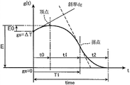
Specifically, at first amount of movement calculating part 22 makes the value (step S22) of the synthetic translational speed V of the current mobile object thing of the temporary transient storage of storer 5, unit interval change function g (t) (step S24) when calculating afterwards deceleration stopping period time and stopping.At this, amount of movement calculating part 22 calculates as the deceleration stopping period time that meets the following conditions and unit interval change function g (t) when stopping: during the stopping of beginning period of deceleration stopping period time, the value gs of unit interval change function g (t) equates with setting unit interval Δ T, during the stopping of the tail end of deceleration stopping period time, the value ge of unit interval change function g (t) is 0, and the synthetic translational speed in beginning period of deceleration stopping period time equates with described synthetic translational speed V.This deceleration stopping period time and when stopping unit interval change function g (t) computation process as shown in Figure 9.In addition, this Fig. 9 shows and restart accelerating period time and the calculating of unit interval change function g (t) and the speed in speed change process also can be suitable in the calculating of unit interval change function g (t) when time and speed change between conversion period jointly when restarting process in restart procedure described later.Namely, amount of movement calculating part 22 in the action along with the velocity variations of following the mobile object thing of implementing to special instruction input media 122 input special instructions, by common computation process calculate this action of following speed fluctuation required during time and be illustrated in the unit interval change function g (t) of the change of the unit interval in time during this period.
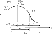
in the beginning period of deceleration stopping period time (amount of movement calculating part 22 receives the time point of emergency stop request) when the mobile object thing moves with constant speed, when stopping, unit interval change function g (t) for example represents with as shown in figure 10 curve, in the time of in beginning mobile object in the period thing of deceleration stopping period time is in acceleration, when stopping, unit interval change function g (t) for example represents with as shown in figure 11 curve, in the time of in beginning mobile object in the period thing of deceleration stopping period time is in deceleration, when stopping, unit interval change function g (t) for example represents with as shown in figure 12 curve.
At first amount of movement calculating part 22 obtains the second differential value j of unit interval change function g (t) when stopping and the slope a (step S42) of the subdifferential of unit interval change function g (t) when stopping when calculating deceleration stopping period time and stopping during unit interval change function g (t).At this moment, described second differential value j obtains by following formula (3), and the slope a of a described subdifferential obtains by following formula (4).
j=J/V ……(3)
a=A/V ……(4)
Wherein, J allows that suddenly one is moving on the synthetic moving direction of mobile object thing, and A is the allowable acceleration on the synthetic moving direction of mobile object thing.The value of these J and A is the parameter of setting for the computation process of the time of present embodiment and g (t).The value of J is set to the value of half left and right of moving suddenly of allowing based on the acceleration and deceleration condition of the mechanical property regulation of lathe, and the value of A is set to the value based on half left and right of the allowable acceleration of the acceleration and deceleration condition of the mechanical property regulation of lathe.
When then, 22 judgements of amount of movement calculating part stop, whether the differential value dg based on benchmark moment t of unit interval change function g (t) is (step S44) more than 0 in the value of the point of t=0.At this, amount of movement calculating part 22 is 0 when above in the value that is judged as this dg, to be set as-j (step S46) by the second differential value j1 of the first half of the quafric curve of unit interval change function g (t) expression when stopping, on the other hand, less than 0 o'clock, described second differential value j1 is set as j (step S48) in the value that is judged as this dg.
then, relative position (the t0 of the starting point of unit interval change function g (t) when when amount of movement calculating part 22 calculates stopping in deceleration stopping period time by following formula (5) and (6) temporarily, the summit of the first half of the quafric curve of unit interval change function g (t) stops with respect to this, E0), and the variable quantity E (step S50) of the value of unit interval change function g (t) during stopping in calculating from the summit of the first half of this quafric curve to the scope of the latter half of terminal point of this quafric curve by following formula (7) is interim.
t0=-dg/j1 ……(5)
E0=(dg/2)×t0 ……(6)
E=ge-gs-E0 ……(7)
When then, amount of movement calculating part 22 judges described stopping, whether the variable quantity E of the value of unit interval change function g (t) is (step S52) more than 0.At this, amount of movement calculating part 22 is 0 when above being judged as described variable quantity E, in the time of stopping, the second differential value j1 of the first half of the quafric curve of unit interval change function g (t) is set as j, and the latter half of second differential value j2 of the quafric curve of unit interval change function g (t) is set as-j (step S54) will stop the time.On the other hand, amount of movement calculating part 22 was judged as described variable quantity E less than 0 o'clock, the second differential value j1 of the first half of described quafric curve is set as-j, and the latter half of second differential value j2 of described quafric curve is set as j, further with positive and negative set conversely (the step S56) of the slope a of the subdifferential of described g (t).
Then, amount of movement calculating part 22 by described formula (5), when (6) are recomputated and are stopped the summit of the first half of the quafric curve of unit interval change function g (t) with respect to the relative position (t0 of the starting point of this quafric curve, E0), and by described formula (7) recomputate from the summit of the first half of this quafric curve to the variable quantity E (step S58) of the g (t) of the scope of latter half of terminal point.
then, amount of movement calculating part 22 calculates respectively the value gu of the g (t) on the summit of the first half of the quafric curve of unit interval change function g (t) when stopping, arrive from the starting point of this quafric curve the time t1 that flex point spends, the time t2 that reaches home and spend from the flex point of this quafric curve, variable quantity G1 from the starting point of this quafric curve to the g (t) of the scope of flex point, from the variable quantity G2 of the g (t) of the flex point scope to terminal of this quafric curve and from the variable quantity G (step S60) of the g (t) of the starting point scope to terminal of this quafric curve.At this moment, amount of movement calculating part 22 calculates described gu by following formula (8), calculates described t1 by following formula (9), calculates described t2 by following formula (10).In addition, amount of movement calculating part 22 calculates described G1 by following formula (11), calculates described G2 by following formula (12), calculates described G by following formula (13).
gu=gs+E0 ……(8)
t1=a/j1 ……(9)
t2=-a/j2 ……(10)
G1=(a/2)×t1 ……(11)
G2=(a/2)×t2 ……(12)
G=G1+G2 ……(13)
Then, amount of movement calculating part 22 judgement is from the summit of the first half of described quafric curve to the absolute value of the variable quantity of the g (t) of the scope of latter half of terminal point | and whether E| is the absolute value from the variable quantity of the g (t) of the starting point scope to terminal of described quafric curve | more than G| (step S62).At this, at described absolute value | E| is described absolute value | when G| is above, as shown in figure 13, and there is the situation of line part corresponding being situated between between the first half curve part of described quafric curve and later half curve part.Therefore, amount of movement calculating part 22 is being judged as described absolute value | and E| is described absolute value | when G| is above, unit interval change function g (t) (step S64) when obtaining respectively the interval T2≤t of the interval T1<t of the interval 0≤t of the first half curve part of described quafric curve≤T1, line part<T2 and later half curve part≤this Three regions of time stopping separately.
Unit interval change function g (t) when specifically, amount of movement calculating part 22 calculates the stopping of interval of 0≤t≤T1 by following formula (14).
g(t)=gu+(j1/2)×(t-t0)
2 ……(14)
Unit interval change function g (t) when in addition, amount of movement calculating part 22 is obtained the stopping of interval of T1<t<T2 by following formula (15).
g(t)=gu+G1+a×(t-T1) ……(15)
Unit interval change function g (t) when in addition, amount of movement calculating part 22 is obtained the stopping of interval of T2≤t≤time by following formula (16).
g(t)=ge+(j2/2)×(t-time)
2 ……(16)
In addition, in this case, described T1 arrives from the starting point of described quafric curve the time that the first flex point (terminal point of first half curve part) spends, and is to obtain by following formula (17).In addition, described T2 arrives from the starting point of described quafric curve the time that Second Inflexion Point (terminal point of line part) spends, and is to obtain by following formula (18).In addition, deceleration stopping period time is the time of reaching home and spending from the starting point of described quafric curve, therefore obtains by following formula (19).
T1=t0+t1 ……(17)
T2=T1+(E-G)/a ……(18)
time=T2+t2 ……(19)
On the other hand, in the situation that described absolute value | E| is less than described absolute value | G|, and corresponding to do not have line part and these two situations that curve part is continuous between the first half curve part of described quafric curve and later half curve part.Therefore, amount of movement calculating part 22 is in the situation that be judged as described absolute value | and E| is less than described absolute value | G|, unit interval change function g (t) (step S65) when obtaining respectively the interval T1<t of the interval 0≤t of the first half curve part of described quafric curve≤T1 and later half curve part≤time these two intervals stopping separately.
Unit interval change function g (t) when specifically, amount of movement calculating part 22 is obtained the stopping of interval of 0≤t≤T1 by following formula (20).
g(t)=gu+(j1/2)×(t-t0)
2 ……(20)
Unit interval change function g (t) when in addition, amount of movement calculating part 22 is obtained the stopping of interval of T1<t≤time by following formula (21).
g(t)=ge+(j2/2)×(t-time)
2 ……(21)
In addition, in this case, deceleration stopping period time obtains by following formula (22).
time=T1+t2 ……(22)
At this, T1 arrives from the starting point of described quafric curve the time that flex point (terminal point of first half curve part) spends, and obtains by following formula (23).
T1=t0+t1 ……(23)
In addition, t1 obtains by following formula (24), and t2 obtains by following formula (25).
t1=[2×E×j2/{j1×(j2-j1)}]
1/2 ……(24)
t2=-j1/j2×t1 ……(25)
Obtain unit interval change function g (t) and deceleration stopping period time when stopping by above method.
Then, amount of movement calculating part 22 is initially set to 0 (the step S26 of Fig. 6) with benchmark moment t.
Afterwards, amount of movement calculating part 22 makes benchmark t increase constantly 1 (step S28), then, based on obtain as described above stop the time unit interval change function g (t) calculate setting in this emergent stopping process (deceleration stopping period time) unit interval, when deceleration of T set unit interval dT2 (step S30) constantly.The length of the length of setting unit interval dT2 during the deceleration that calculates at this moment, for reducing from the length by the setting unit interval Δ T under the state before acceleration and deceleration request monitoring unit 10 output emergency stop request, state before the emergency stop push button 124a of halt instruction input media 124 is pressed.Amount of movement calculating part 22 calculates by unit interval change function g (t) when increasing benchmark after 1 at described step S28 the t substitution stops constantly and sets unit interval dT2 when slowing down.
Set the amount of movement dP[axis on each shifting axle in unit interval dT2 when then, amount of movement calculating part 22 calculates each and slows down by following formula (27)], from set T to T+dT2 constantly during each shifting axle on amount of movement dP[axis] (step S32).
dP[axis]=path(T+dT2)[axis]path(T)[axis] ……(27)
Set the amount of movement dP[axis on each shifting axle in unit interval dT2 when each that as above obtain slowed down] less than the amount of movement on each shifting axle in each the setting unit interval Δ T under the state before exporting emergency stop request by acceleration and deceleration request monitoring unit 10.
Afterwards, same with described step S12, set the amount of movement dP[axis on each shifting axle in unit interval dT2 when drive control part 14 slows down according to each that is calculated by amount of movement calculating part 22] each drive unit 102c, 106b, 108b, 110b are driven, make these drive units 102c, 106b, 108b, 110b in the time, supporting mass 102b, 106a, 108a, the 110a of correspondence be carried the amount of movement dP[axis on corresponding each shifting axle in each base] (step S34).
Setting unit interval dT2 when then, amount of movement calculating part 22 will be set T constantly with the deceleration that calculates at described step S30 upgrades and sets T (step S36) constantly in the Calais mutually.
Afterwards, amount of movement calculating part 22 judgment standards constantly t whether reach deceleration stopping period time above (step S38).At this, in the situation that benchmark moment t is that more than deceleration stopping period time, the movement of mobile object thing stops.Amount of movement calculating part 22 in the situation that be judged as benchmark constantly t be more than deceleration stopping period time, then, read in the value (step S40) that is stored in the synthetic translational speed V in storer 5.Afterwards, in the situation that inputted restart indication to restart indication input media 126, the restart procedure (with reference to Fig. 7) that the movement of mobile object thing is restarted.On the other hand, amount of movement calculating part 22 does not pass through deceleration stopping period time in the situation that described step S38 is judged as benchmark moment t, again carries out the later processing of described step S28.
The restart procedure of mobile object thing then, is described.In this restart procedure, amount of movement calculating part 22 judges whether to have exported the request of restarting (step S68) from acceleration and deceleration request monitoring unit 10.At this, amount of movement calculating part 22 carries out the judgement of this step S68 repeatedly in the situation that be not judged as from 10 outputs of acceleration and deceleration request monitoring unit and restart request.On the other hand, amount of movement calculating part 22 is in the situation that be judged as from acceleration and deceleration request monitoring unit 10 and exported the request of restarting, then, calculate unit interval change function g (t) (step S70) when restarting accelerating period time and restarting.At this moment, amount of movement calculating part 22 calculate meet the following conditions restart accelerating period time and unit interval change function g (t) when restarting: during the restarting of beginning period of restarting accelerating period time, the value gs of unit interval change function g (t) is 0, during the restarting of tail end of restarting accelerating period time, the value ge of unit interval change function g (t) equates with the current coefficient k of controlling, and the synthetic translational speed that restarts the tail end of accelerating period time is described synthetic translational speed V.This restart accelerating period time and when restarting the computation process of unit interval change function g (t) with described deceleration stopping period time and when stopping the unit interval changing computation process (the step S42 of Fig. 9~S65) identical of function g (t).In addition, in this computation process, described t0 and described E0 are 0, and described dg is 0.
unit interval change function g (t) when restarting is in the situation that from the absolute value of the variable quantity of the g (t) to the terminal point of later half quafric curve interval with the vertex of a conic of the first half of its function representation | and E| is again the absolute value of the variable quantity of the g (t) of time during Acceleration of starting | more than G|, there is the curve of line part to represent with being situated between between first half curve part and later half curve part as shown in figure 14, in the situation that described absolute value | E| is less than described absolute value | G|, there is not line part and continuous curve represents with as shown in figure 15 first half curve part and later half curve part.
Then, amount of movement calculating part 22 calculate restart accelerating period time and when restarting unit interval change function g (t) afterwards, similarly carry out the process of the step S72 of Fig. 7~S84 with the step S26 of described Fig. 6~process of S38.At this moment, amount of movement calculating part 22 step S76 based on calculate at step S70 restart the time unit interval change function g (t) calculate and set unit interval dT2 when accelerating, and at step S78, set the amount of movement dP[axis on each shifting axle in unit interval dT2 when calculating this acceleration that each calculates].By carrying out restart procedure as above, the mobile mobile object thing that stops restarts mobile, and accelerates to and the current corresponding speed of coefficient k of controlling.
Then, amount of movement calculating part 22 in the situation that be judged as in the judgement of step S84 benchmark constantly t for during Acceleration of starting again more than time, again carry out the later processing of step S8 of Fig. 4.
In addition, amount of movement calculating part 22 afterwards, judges whether to have exported speed change request (step S18) from acceleration and deceleration request monitoring unit 10 in the situation that described step S16 is judged as not from acceleration and deceleration request monitoring unit 10 output emergency stop request.
At this, amount of movement calculating part 22 is in the situation that be judged as from acceleration and deceleration request monitoring unit 10 and exported speed change request, and the speed of implementing mobile object thing shown in Figure 8 changes process.
Specifically, amount of movement calculating part 22 computing velocity unit interval change function g (t) (step S86) during the change of time and speed between conversion period at first.At this moment, amount of movement calculating part 22 calculates the speed that meets the following conditions unit interval change function g (t) when time and speed change between conversion period: during the speed change in speed beginning period of time between conversion period, the value gs of unit interval change function g (t) equates with setting unit interval Δ T, during the change of the speed of speed tail end of time between conversion period, the value ge of unit interval change function g (t) equates with the speed coefficient k of controlling after changing, and the synthetic translational speed in speed beginning period of time between conversion period equates with described synthetic translational speed V.
In addition, in the situation that assisted instruction is imported into actuation means 128, speed between conversion period time be included in the concept in accelerating period of the present invention, in the situation that deceleration instruction is imported into actuation means 128, speed between conversion period time be included in concept between deceleration period of the present invention.In addition, in the situation that assisted instruction is imported into actuation means 128, when during the speed change, unit interval change function g (t) is included in of the present invention the acceleration, the unit interval changes in the concept of function, in the situation that deceleration instruction is input to actuation means 128, when during the speed change, unit interval change function g (t) is included in of the present invention the deceleration, the unit interval changes in the concept of function.
(amount of movement calculating part 22 receives the time point of speed change request) mobile object thing moves with constant speed in the situation that the beginning period of speed time between conversion period, and when carrying out the speed change in the situation of accelerated motion of mobile object thing, unit interval change function g (t) for example represents with as shown in figure 16 curve.On the other hand, in the situation that speed when during between conversion period, beginning mobile object in the period thing of time is in acceleration, further carrying out speed change in the situation of accelerated motion of this mobile object thing unit interval change function g (t) represent with as shown in figure 17 curve.In addition, in the situation that speed when during between conversion period, beginning mobile object in the period thing of time is in deceleration, carrying out speed change in the situation of speed-down action of this mobile object thing unit interval change function g (t) represent with as shown in figure 18 curve.
In addition, (amount of movement calculating part 22 receives the time point of speed change request) mobile object thing moves with constant speed in the situation that the beginning period of speed time between conversion period, and when carrying out the speed change in the situation of speed-down action of mobile object thing, unit interval change function g (t) for example represents with as shown in figure 19 curve.On the other hand, in the situation that speed when during between conversion period, beginning mobile object in the period thing of time is in acceleration, carrying out speed change in the situation of speed-down action of this mobile object thing unit interval change function g (t) represent with as shown in figure 20 curve.In addition, in the situation that speed when during between conversion period, beginning mobile object in the period thing of time is in deceleration, further carrying out speed change in the situation of speed-down action of this mobile object thing unit interval change function g (t) represent with as shown in figure 21 curve.
In addition, described Figure 16~Figure 21 all with the vertex of a conic of the first half of the change function g of unit interval when changing with speed (t) the expression absolute value to the variable quantity of the g (t) in the interval of the terminal point of later half quafric curve | E| is less than the absolute value of the variable quantity of the g (t) of speed time between conversion period | the situation of G| is corresponding, when in these cases, speed changes, the curve of unit interval change function g (t) continuous shape by not having line part between first half curve part and later half curve part represents.On the other hand, in the situation that described absolute value | E| is described absolute value | G| is above, and first half curve part and the later half curve part by these each figure is situated between and the unit interval changes function g (t) when the curve of the shape that is connected by line part comes the change of expression speed.
Then, amount of movement calculating part 22 computing velocity between conversion period during the change of time and speed unit interval change function g (t) afterwards, benchmark t constantly is set to 0 (step S88), afterwards, make benchmark constantly t increase by 1 (step S89).
When then, amount of movement calculating part 22 changes based on the speed that calculates at step S86, unit interval change function g (t) calculates and sets unit interval Δ T (step S90).This setting unit interval Δ T is that unit interval change function g (t) obtains by with the benchmark t substitution speed change constantly that increases at described step S89 after 1 time.
Then, amount of movement calculating part 22 and described step S10 similarly calculate the unit interval amount of movement dP[axis on each interior shifting axle of each this setting unit interval Δ T that calculates] (step S91).
Then, amount of movement calculating part 22 is based on the unit interval amount of movement dP[axis on each shifting axle that calculates at described step S91], calculate the synthetic translational speed V (step S92) of current mobile object thing.The computing method that should synthesize translational speed V are identical with the computing method of the synthetic translational speed V of described step S11.
Afterwards, drive control part 14 is according to the amount of movement dP[axis that calculates at described step S91], similarly each drive unit 102c, 106b, 108b, 110b are driven (step S93) with described step S12.Afterwards, amount of movement calculating part 22 will be set T constantly and upgrade this setting moment T (step S94) with the setting unit interval Δ T phase Calais that calculates at described step S90.
Then, amount of movement calculating part 22 unit interval change function g (t) when constantly t is to the speed change obtained at described step S86 with benchmark carries out differential and calculates described dg (step S95).
Afterwards, amount of movement calculating part 22 judgment standards constantly t be whether that speed is between conversion period more than time.Amount of movement calculating part 22 in the situation that be judged as benchmark constantly t be speed between conversion period more than time, again carry out the later processing of described step S8.On the other hand, amount of movement calculating part 22 in the situation that be judged as benchmark constantly t without the speed of mistake time between conversion period, then, similarly judge whether to have exported emergency stop request (step S97) from acceleration and deceleration request monitoring unit 10 with described step S16.
At this, amount of movement calculating part 22 is implemented the emergent stopping process of described step S22~S38 in the situation that be judged as from acceleration and deceleration request monitoring unit 10 and exported emergency stop request.In addition, amount of movement calculating part 22 is in the situation that be judged as not from acceleration and deceleration request monitoring unit 10 output emergency stop request, then, similarly judge whether to have exported speed change request (step S98) from acceleration and deceleration request monitoring unit 10 with described step S18.At this, amount of movement calculating part 22 is implemented the later speed change process of described step S86 again in the situation that be judged as from acceleration and deceleration request monitoring unit 10 and exported speed change request.On the other hand, amount of movement calculating part 22 carries out the later process of described step S89 again in the situation that be not judged as from the 10 output speeds change requests of acceleration and deceleration request monitoring unit.
In addition, amount of movement calculating part 22 is not in the situation that be judged as in the judgement of described step S18 from the 10 output speeds change requests of acceleration and deceleration request monitoring unit, will set constantly T and set unit interval Δ T phase Calais and upgrade setting moment T (step S20).Afterwards, again carry out the later process of described step S10.
Implement as described above the Numerical Control process of the numerical control device 2 of present embodiment.
as discussed above, in the present embodiment, make conveying device 102, 106, 108, irregular action (the emergent stopping of the velocity variations of mobile object thing is followed in 110 enforcements, follow acceleration restart and mobile in the acceleration and deceleration of mobile object thing) time, length in the setting unit interval common on each shifting axle direction is the velocity variations corresponding length indicated with this special instruction from the length variations under the state before special instruction input media 122 input special instructions, and according to each supporting mass 102b in the setting unit interval after each this variation that calculates based on machining path, 106a, 108a, the amount of movement of 110a on the shifting axle direction of correspondence, carry each supporting mass 102b, 106a, 108a, 110a.Therefore, supporting mass 102b, 106a on each shifting axle direction in the setting unit interval after each the described variation that calculates based on machining path, the amount of movement of 108a, 110a become have been kept each that stipulate by machining path and has moved the amount of movement of the relative position relationship between axial position, becomes with the conveying of corresponding each supporting mass 102b of this amount of movement, 106a, 108a, 110a the conveying of having kept under the state that each that stipulate by machining path move the relative position relationship between axial position.Its result, making conveying device 102,106,108,110 in the situation that carry out the action (emergent stopping, the acceleration from restarting, the acceleration and deceleration of mobile object thing mobile) of the irregular velocity variations of following this mobile object thing of the common conveying that is different from the mobile object thing during processing work 100, can prevent that the motion track of mobile object thing from deviating from machining path.
in addition, in the present embodiment, even unlike the technology of carrying out in addition for the described patent documentation 1 of the computing of eliminating the error that produces because of described interpolation speed controlling after interpolating, carry out the technology of the described patent documentation 2 of the front acceleration and deceleration computing of described interpolation and carry out like that the complex calculations processing when having inputted special instruction to special instruction input media 122, also can deviate from machining path at the motion track that prevents the mobile object thing by the simple processing as the length that changes the common setting unit interval on each shifting axle direction, and, can implement to follow the action of the irregular velocity variations of this mobile object thing, therefore, can improve by indicating the action of the velocity variations of following the mobile object thing to rise to conveying device 102 to special instruction input media 122 input special instructions, 106, 108, response till the action of 110 actual these mobile object things of execution.Specifically, can improve to the instruction of halt instruction input media input emergent stopping and play response till conveying device 102,106,108, the 110 actual mobile emergent stoppings that make the mobile object thing.In addition, can improve to restart indication input media 126 input restart indications and play response till restarting to conveying device 102,106,108, the 110 actual movements that make the mobile object thing.In addition, can improve to actuation means 128 input speed alteration commands and play response till conveying device 102,106,108, the 110 actual mobile acceleration or decelerations that make the mobile object thing.
in addition, in the present embodiment, make conveying device 102, 106, 108, 110 implement to follow in the situation of irregular action of velocity variations of mobile object thing, set with as drive unit 102c, 106b, 108b, the benchmark moment of the benchmark of the driving of 110b and the setting moment and the unit interval of setting that are different from base's time, calculate each supporting mass 102b in each this setting unit interval based on machining path, 106a, 108a, the amount of movement of 110a on the shifting axle direction of correspondence, calculate thus and should make each supporting mass 102b in the time in each base, 106a, 108a, the amount of movement that 110a moves.Namely, in the present embodiment, in the situation that not to as the benchmark of the benchmark of the driving of drive unit 102c, 106b, 108b, 110b constantly and base exert an influence the time, calculate each supporting mass 102b, 106a, 108a, 110a of the irregular action of the velocity variations that is used for implementing following the mobile object thing at each amount of movement of base in the time.Therefore, the common driving of each drive unit 102c, 106b, 108b, 110b do not exerted an influence, can implement to follow the action of the irregular velocity variations of mobile object thing.
In addition, should think to be example on this disclosed embodiment in all respects, and be not restrictive embodiment.Scope of the present invention is not by the explanation of described embodiment but represents by claims, also comprises and the implication of claims equalization and all changes in scope.
For example, numerical control device of the present invention also goes for the lathe in addition of the lathe shown in described embodiment.
In addition, move path leading-out portion also can possess interpolation arithmetic unit, acceleration and deceleration wave filter.Namely, also can movement-based command path leading-out portion do not carry out interpolation arithmetic and move path on each shifting axle of deriving from the machining path of processing instruction repertorie, the amount of movement calculating part calculates each and sets the amount of movement of each supporting mass on the shifting axle direction of correspondence in unit interval.
Deceleration when in addition, the numerical control device of the present invention conveying device of carrying out is controlled the emergent stopping that also can be applicable to the mobile object thing, the acceleration when restarting and the acceleration and deceleration undertaken by actuation means whole.For example, also can be only the applicable numerical control device of the present invention of deceleration during to the emergent stopping of the mobile object thing conveying device of carrying out control, also can be only the applicable numerical control device of the present invention of acceleration during to the restarting of the mobile object thing conveying device of carrying out control, the conveying device of also can be only the applicable numerical control device of the present invention of acceleration and deceleration of the mobile object thing that undertaken by actuation means being carried out is controlled.In addition, the conveying device that wherein two the applicable numerical control devices of the present invention in the deceleration in the time of also can be to the emergent stopping of mobile object thing, the acceleration when restarting and the acceleration and deceleration undertaken by actuation means carry out is controlled.In these cases, stop signal input media, the device that restarts in signal input apparatus and actuation means the action that is used to indicate the velocity variations of following the mobile object thing of the control that applicable numerical control device of the present invention carries out are included in special instruction input media of the present invention.
[summary of embodiment]
Conclude described embodiment as follows.
the numerical control device that described embodiment is related is arranged at lathe, and described lathe possesses: a plurality of conveying devices, workpiece or the cutter of processing this workpiece as the mobile object thing, are carried described mobile object thing when the described workpiece of processing, and special instruction input media, be used for from outside input special instruction, this special instruction is used to indicate the action of the velocity variations of following this mobile object thing of the common conveying that is different from described mobile object thing when the described workpiece of processing, wherein, described each conveying device has respectively: the supporting mass that supports described mobile object thing, and by thereby this supporting mass is carried the drive unit of described mobile object thing along specific shifting axle direction, described numerical control device carries out the Numerical Control to described each conveying device, comprise: storage part, store predetermined the processing instruction repertorie of machining path, this machining path be illustrated in processing during described workpiece described mobile object thing follow benchmark constantly process and the path that should move, operational part based on described machining path, calculates respectively the amount of movement of described each supporting mass on the described shifting axle direction of correspondence in each a certain setting unit interval, and drive control part, amount of movement according to described each supporting mass that is calculated by described operational part, make described each drive unit carry the described supporting mass corresponding with this drive unit, wherein, described operational part, response is input to the described special instruction of described special instruction input media, the length that makes the described setting unit interval is the length corresponding with the velocity variations of the indicated described mobile object thing of this special instruction from the length variations of inputting under the state before this special instruction, and the amount of movement of described each supporting mass on the described shifting axle direction of correspondence in the setting unit interval after calculating each and change its length based on described machining path.
in this numerical control device, when the irregular action of the velocity variations that lathe is implemented follow the mobile object thing, length in the setting unit interval common on each shifting axle direction is the velocity variations corresponding length indicated with this special instruction from the length variations under the state before the described special instruction of input, and the amount of movement of each supporting mass on the shifting axle direction of correspondence in the setting unit interval after calculating each and change its length based on machining path, according to this amount of movement that calculates, each supporting mass is transported on corresponding moving direction.Therefore, in the situation that be different from the common conveying of mobile object thing during the processing of workpiece and carry out the action of the irregular velocity variations of following this mobile object thing, can prevent that the motion track of mobile object thing from deviating from machining path.
Specifically, as this numerical control device according to as described in special instruction change in the situation that the length of common setting unit interval on each shifting axle direction, each supporting mass in each this setting unit interval that calculates based on machining path is calculated as the amount of movement of having kept the relative position relationship between each shifting axle of stipulating by machining path at the amount of movement on the shifting axle direction of correspondence.Therefore, when the amount of movement on each shifting axle direction in this setting unit interval that drive unit calculates according to each is carried corresponding supporting mass, under the state of keeping the relative position relationship between each shifting axle of stipulating by machining path, the action of the velocity variations of mobile object thing is followed in enforcement.Its result even implemented the action of following the velocity variations of irregular mobile object thing as above, can prevent that also the motion track of mobile object thing from deviating from described machining path.
in addition, in this numerical control device, even unlike the technology of carrying out in addition for the described patent documentation 1 of the computing of eliminating the error that produces by described interpolation speed controlling after interpolating, carry out the technology of the described patent documentation 2 of the front acceleration and deceleration computing of described interpolation and carry out like that the complex calculations processing when having inputted special instruction to the special instruction input media, also can prevent that the mobile object thing from deviating from machining path by the simple processing as the length of setting the unit interval as described in changing, and, can implement to follow the action of the irregular velocity variations of this mobile object thing, therefore, can improve by indicate the action of the velocity variations of following the mobile object thing to rise to the actual execution of conveying device to special instruction input media input special instruction and follow response till the action of velocity variations of this mobile object thing.
in described numerical control device, preferably: described drive control part, action to described each drive unit is controlled, so that this each drive unit is carried the described amount of movement in each the described setting unit interval calculated by described operational part on the described shifting axle direction of corresponding described supporting mass in correspondence in the time in each base, wherein, the driving benchmark that described base is this each drive unit the time, described operational part, the described setting unit interval is set as the unit interval that is different from the described base time, calculate the amount of movement of described each supporting mass on the described shifting axle direction of correspondence in each this setting unit interval based on described machining path.
According to this structure, in order the base as the benchmark of the driving of drive unit not to be exerted an influence the time and implement to follow the action of the irregular velocity variations of mobile object thing, calculate each drive unit is carried in each base the supporting mass of correspondence in the time operational throughput (amount of movement) on the shifting axle direction of correspondence, can carry out and the corresponding conveying of each supporting mass on corresponding shifting axle direction of this operational throughput.Therefore, the driving of each drive unit do not exerted an influence and can implement to follow the action of the irregular velocity variations of mobile object thing.
in described numerical control device, preferably: described special instruction input media comprises the halt instruction input media, this halt instruction input media is used for and will promptly slows down and the emergent stopping instruction that stops is inputted as described special instruction be used to the movement that makes described mobile object thing, described operational part, response is input to the described emergent stopping instruction of described halt instruction input media, the described setting unit interval when stopping in unit interval change function calculation deceleration stopping period, and calculate the amount of movement of described each supporting mass on the described shifting axle direction of correspondence in each this setting unit interval that calculates based on described machining path, wherein, during described stopping, unit interval change function is to make the length of described setting unit interval be reduced to 0 function at the described deceleration stopping period of regulation from the length under the state before the described emergent stopping instruction of described halt instruction input media input.
In this structure, if to the instruction of halt instruction input media input emergent stopping, the amount of movement that each on the shifting axle direction of correspondence of each supporting mass set in the unit interval is reduced to 0, can the mobile object thing be stopped.And, in this structure, make the length of described setting unit interval be reduced to 0, and calculate each its length based on machining path and be reduced to the amount of movement of each supporting mass on the shifting axle direction of correspondence in setting unit interval of 0, therefore can prevent that the motion track of this mobile object thing when making mobile object thing emergent stopping from deviating from machining path, and can improve and play the response till actual execution the to the emergent stopping of mobile object thing to the instruction of halt instruction input media input emergent stopping.
in this case, preferably: described special instruction input media comprises the restart indication input media, this restart indication input media is used for and will inputs as described special instruction be used to the restart indication that the movement that stops mobile described mobile object thing is restarted and accelerate, described operational part, response is being input to the described restart indication of described restart indication input media after the described emergent stopping instruction of described halt instruction input media input, the unit interval change described described setting unit interval of restarting in the accelerating period of function calculation when restarting, and calculate the amount of movement of described each supporting mass on the described shifting axle direction of correspondence in each this setting unit interval that calculates based on described machining path, wherein, what during described restarting, unit interval change function was the length that makes the described setting unit interval in regulation restarts the accelerating period from 0 function that increases to length-specific.
In this structure, if according to described emergent stopping instruction and the mobile object thing is under the state that stops to restart indication input media input restart indication, correspondingly increase to specific amount of movement with the increase of setting the unit interval at described each amount of movement set in unit interval that makes in the accelerating period on the shifting axle direction of each supporting mass in correspondence that restarts from 0, can implement to follow the restarting of acceleration of mobile object thing.And, in this structure, the length of described setting unit interval is increased to length-specific from 0, and calculate the amount of movement of each supporting mass on the shifting axle direction of correspondence in the setting unit interval that each its length increases based on machining path, therefore, can prevent that the motion track of this mobile object thing from deviating from machining path when the mobile mobile object thing that stops is restarted, and can improve to restart indication input media input restart indication and play restarting and accelerating response till actual execution to the mobile object thing.
in described numerical control device, preferably: described special instruction input media comprises speed alteration command input media, this speed alteration command input media can will speed up instruction or deceleration instruction is inputted as described special instruction, wherein, described assisted instruction comprises the indication of the translational speed rising that makes described mobile object thing and the escalating rate of this translational speed, be the information of rate of acceleration, described deceleration instruction comprises the indication of the translational speed decline that makes described mobile object thing and the rate of descent of this translational speed, be the information of the rate of deceleration, described operational part, response is input to the described assisted instruction of described speed alteration command input media, the change described setting unit interval of function calculation in described accelerating period unit interval during based on acceleration, calculate the amount of movement of described each supporting mass on the described shifting axle direction of correspondence in each this setting unit interval that calculates based on described machining path, on the other hand, response is input to the described deceleration instruction of described speed alteration command input media, the described setting unit interval of unit interval change function calculation between described deceleration period when slowing down, calculate the amount of movement of described each supporting mass on the described shifting axle direction of correspondence in each this setting unit interval that calculates based on described machining path, wherein, during described accelerate, to be the length that makes the described setting unit interval increase to the function of the corresponding length of the described rate of acceleration that comprises with described assisted instruction to unit interval change function from the length under the state before the described assisted instruction of described speed alteration command input media input in accelerating period of regulation, during described slow down, unit interval change function is that the length that makes the described setting unit interval is reduced to the function of the corresponding length of the described rate of deceleration that comprises with described deceleration instruction between the deceleration period of regulation from input length under the state before described deceleration instruction to described speed alteration command input media.
in this structure, if to speed alteration command input media input assisted instruction, increase to from the amount of movement within each the setting unit interval before speed alteration command input media input assisted instruction the acceleration that the corresponding amount of movement of the rate of acceleration that comprises with assisted instruction can be implemented the mobile object thing at each amount of movement set in the unit interval on the shifting axle direction of described accelerated period each supporting mass of chien shih in correspondence, on the other hand, if to speed alteration command input media input deceleration instruction, the amount of movement that each on the shifting axle direction of correspondence of each supporting mass set in the unit interval is reduced to from the amount of movement within each the setting unit interval before speed alteration command input media input deceleration instruction the deceleration that the corresponding amount of movement of the rate of deceleration that comprises with deceleration instruction can be implemented the mobile object thing.and, in this structure, when having inputted assisted instruction to speed alteration command input media, the described setting unit interval is increased, and calculate the amount of movement of each supporting mass on the shifting axle direction of correspondence in the setting unit interval that each its length increases based on machining path, on the other hand, when having inputted deceleration instruction to speed alteration command input media, the described setting unit interval is reduced, and calculate the amount of movement of each supporting mass on the shifting axle direction of correspondence in the setting unit interval that each its length reduces based on machining path, therefore, the motion track that can prevent this mobile object thing when the translational speed that makes the mobile object thing and input to the assisted instruction of speed alteration command input media or deceleration instruction correspondingly change when processing work deviates from machining path, and can improve to speed alteration command input media input assisted instruction or deceleration instruction and play response till the actual execution of the acceleration or deceleration of mobile object thing.
As discussed above, according to described embodiment, in the situation that implement to be different from the action of the velocity variations of following this mobile object thing of the common conveying of mobile object thing in lathe during processing work, the motion track that can prevent the mobile object thing deviates from the machining path by the indication of processing instruction repertorie, and can improve indication and follow the action of the velocity variations of mobile object thing to play response till this action executing.
Claims (5)
1. a numerical control device, be arranged at lathe, and described lathe possesses:
A plurality of conveying devices as the mobile object thing, are carried described mobile object thing with workpiece or the cutter of processing this workpiece when the described workpiece of processing; And
The special instruction input media is used for from outside input special instruction, and this special instruction is used to indicate the action of the velocity variations of following this mobile object thing of the common conveying that is different from described mobile object thing when the described workpiece of processing, wherein,
Described each conveying device has respectively: support the supporting mass of described mobile object thing, thereby and by this supporting mass being carried the drive unit of described mobile object thing along specific shifting axle direction,
Described numerical control device carries out the Numerical Control to described each conveying device, it is characterized in that comprising:
Storage part, store predetermined the processing instruction repertorie of machining path, this machining path be illustrated in processing during described workpiece described mobile object thing follow benchmark constantly process and the path that should move;
Operational part based on described machining path, calculates respectively the amount of movement of described each supporting mass on the described shifting axle direction of correspondence in each a certain setting unit interval; And
Drive control part according to the amount of movement of described each supporting mass that is calculated by described operational part, makes described each drive unit carry the described supporting mass corresponding with this drive unit, wherein,
Described operational part, response is input to the described special instruction of described special instruction input media, the length that makes the described setting unit interval is the length corresponding with the velocity variations of the indicated described mobile object thing of this special instruction from the length variations of inputting under the state before this special instruction, and the amount of movement of described each supporting mass on the described shifting axle direction of correspondence in the setting unit interval after calculating each and change its length based on described machining path.
2. numerical control device according to claim 1 is characterized in that:
Described drive control part, action to described each drive unit is controlled, so that this each drive unit is carried the described amount of movement in each the described setting unit interval calculated by described operational part on the described shifting axle direction of corresponding described supporting mass in correspondence in the time in each base, wherein, the driving benchmark that described base is this each drive unit the time
Described operational part is set as with the described setting unit interval unit interval that is different from the described base time, calculates the amount of movement of described each supporting mass on the described shifting axle direction of correspondence in each this setting unit interval based on described machining path.
3. numerical control device according to claim 1 and 2 is characterized in that:
Described special instruction input media comprises the halt instruction input media, and this halt instruction input media is used for and will promptly slows down and the emergent stopping instruction that stops is inputted as described special instruction be used to the movement that makes described mobile object thing,
described operational part, response is input to the described emergent stopping instruction of described halt instruction input media, the described setting unit interval when stopping in unit interval change function calculation deceleration stopping period, and calculate the amount of movement of described each supporting mass on the described shifting axle direction of correspondence in each this setting unit interval that calculates based on described machining path, wherein, during described stopping, unit interval change function is to make the length of described setting unit interval be reduced to 0 function at the described deceleration stopping period of regulation from the length under the state before the described emergent stopping instruction of described halt instruction input media input.
4. numerical control device according to claim 3 is characterized in that:
Described special instruction input media comprises the restart indication input media, and this restart indication input media is used for and will inputs as described special instruction be used to the restart indication that the movement that stops mobile described mobile object thing is restarted and accelerate,
described operational part, response is being input to the described restart indication of described restart indication input media after the described emergent stopping instruction of described halt instruction input media input, the unit interval change described described setting unit interval of restarting in the accelerating period of function calculation when restarting, and calculate the amount of movement of described each supporting mass on the described shifting axle direction of correspondence in each this setting unit interval that calculates based on described machining path, wherein, what during described restarting, unit interval change function was the length that makes the described setting unit interval in regulation restarts the accelerating period from 0 function that increases to length-specific.
5. the described numerical control device of any one according to claim 1 to 4 is characterized in that:
Described special instruction input media comprises speed alteration command input media, this speed alteration command input media can will speed up instruction or deceleration instruction is inputted as described special instruction, wherein, described assisted instruction comprise indication that the translational speed that makes described mobile object thing rises and this translational speed escalating rate, be the information of rate of acceleration, described deceleration instruction comprise indication that the translational speed that makes described mobile object thing descends and this translational speed rate of descent, be the information of the rate of deceleration
described operational part, response is input to the described assisted instruction of described speed alteration command input media, the change described setting unit interval of function calculation in described accelerating period unit interval during based on acceleration, calculate the amount of movement of described each supporting mass on the described shifting axle direction of correspondence in each this setting unit interval that calculates based on described machining path, on the other hand, response is input to the described deceleration instruction of described speed alteration command input media, the described setting unit interval of unit interval change function calculation between described deceleration period when slowing down, calculate the amount of movement of described each supporting mass on the described shifting axle direction of correspondence in each this setting unit interval that calculates based on described machining path, wherein, during described accelerate, to be the length that makes the described setting unit interval increase to the function of the corresponding length of the described rate of acceleration that comprises with described assisted instruction to unit interval change function from the length under the state before the described assisted instruction of described speed alteration command input media input in accelerating period of regulation, during described slow down, unit interval change function is that the length that makes the described setting unit interval is reduced to the function of the corresponding length of the described rate of deceleration that comprises with described deceleration instruction between the deceleration period of regulation from input length under the state before described deceleration instruction to described speed alteration command input media.
Applications Claiming Priority (3)
| Application Number | Priority Date | Filing Date | Title |
|---|---|---|---|
| JP2010171050A JP5331068B2 (en) | 2010-07-29 | 2010-07-29 | Numerical controller |
| JP2010-171050 | 2010-07-29 | ||
| PCT/JP2011/004277 WO2012014479A1 (en) | 2010-07-29 | 2011-07-28 | Numerical control apparatus |
Publications (1)
| Publication Number | Publication Date |
|---|---|
| CN103140817A true CN103140817A (en) | 2013-06-05 |
Family
ID=45529710
Family Applications (1)
| Application Number | Title | Priority Date | Filing Date |
|---|---|---|---|
| CN2011800368997A Pending CN103140817A (en) | 2010-07-29 | 2011-07-28 | Numerical control apparatus |
Country Status (5)
| Country | Link |
|---|---|
| US (1) | US20130123968A1 (en) |
| EP (1) | EP2600217A1 (en) |
| JP (1) | JP5331068B2 (en) |
| CN (1) | CN103140817A (en) |
| WO (1) | WO2012014479A1 (en) |
Cited By (4)
| Publication number | Priority date | Publication date | Assignee | Title |
|---|---|---|---|---|
| CN105549534A (en) * | 2014-10-22 | 2016-05-04 | 发那科株式会社 | Numerical control device |
| CN107885167A (en) * | 2016-09-30 | 2018-04-06 | 兄弟工业株式会社 | Numerical control device |
| CN108427378A (en) * | 2017-02-15 | 2018-08-21 | 发那科株式会社 | Numerical control device |
| CN110412859A (en) * | 2018-04-26 | 2019-11-05 | 精工爱普生株式会社 | Electronic watch |
Families Citing this family (4)
| Publication number | Priority date | Publication date | Assignee | Title |
|---|---|---|---|---|
| JP5417392B2 (en) * | 2011-07-29 | 2014-02-12 | 新日本工機株式会社 | Numerical controller |
| JP5715189B2 (en) | 2013-06-12 | 2015-05-07 | ファナック株式会社 | Numerical control device with a function to smoothly change the feed rate when the override changes |
| JP6034835B2 (en) * | 2014-08-26 | 2016-11-30 | ファナック株式会社 | Numerical control device for presenting information for shortening cycle time |
| JP6396389B2 (en) * | 2016-10-27 | 2018-09-26 | ファナック株式会社 | Servo control device |
Citations (5)
| Publication number | Priority date | Publication date | Assignee | Title |
|---|---|---|---|---|
| US4894596A (en) * | 1987-04-30 | 1990-01-16 | Fanuc Ltd. | Velocity control apparatus |
| JPH11202915A (en) * | 1998-01-16 | 1999-07-30 | Fanuc Ltd | Controller for automatic machine |
| CN1623126A (en) * | 2002-10-30 | 2005-06-01 | 三菱电机株式会社 | Numerical control device |
| CN1722034A (en) * | 2004-06-18 | 2006-01-18 | 发那科株式会社 | Numerical controller |
| CN101563661A (en) * | 2006-11-01 | 2009-10-21 | 沙迪克株式会社 | Working control device, and its program |
Family Cites Families (6)
| Publication number | Priority date | Publication date | Assignee | Title |
|---|---|---|---|---|
| US3557461A (en) * | 1967-04-18 | 1971-01-26 | Disk Pack Corp | Mechanical disc pack tester and method |
| JP2897333B2 (en) * | 1990-04-11 | 1999-05-31 | ブラザー工業株式会社 | Servo control device |
| JPH06110532A (en) * | 1992-09-29 | 1994-04-22 | Intetsuku:Kk | Method for controlling position and device thereof |
| JP3508677B2 (en) * | 2000-02-04 | 2004-03-22 | 三菱電機株式会社 | Robot controller |
| JP5009010B2 (en) | 2007-03-13 | 2012-08-22 | 新日本工機株式会社 | Numerical controller |
| JP5129064B2 (en) | 2008-08-26 | 2013-01-23 | 新日本工機株式会社 | Numerical control device for machine tools |
-
2010
- 2010-07-29 JP JP2010171050A patent/JP5331068B2/en not_active Expired - Fee Related
-
2011
- 2011-07-28 WO PCT/JP2011/004277 patent/WO2012014479A1/en active Application Filing
- 2011-07-28 US US13/812,645 patent/US20130123968A1/en not_active Abandoned
- 2011-07-28 EP EP11812081.5A patent/EP2600217A1/en not_active Withdrawn
- 2011-07-28 CN CN2011800368997A patent/CN103140817A/en active Pending
Patent Citations (5)
| Publication number | Priority date | Publication date | Assignee | Title |
|---|---|---|---|---|
| US4894596A (en) * | 1987-04-30 | 1990-01-16 | Fanuc Ltd. | Velocity control apparatus |
| JPH11202915A (en) * | 1998-01-16 | 1999-07-30 | Fanuc Ltd | Controller for automatic machine |
| CN1623126A (en) * | 2002-10-30 | 2005-06-01 | 三菱电机株式会社 | Numerical control device |
| CN1722034A (en) * | 2004-06-18 | 2006-01-18 | 发那科株式会社 | Numerical controller |
| CN101563661A (en) * | 2006-11-01 | 2009-10-21 | 沙迪克株式会社 | Working control device, and its program |
Cited By (7)
| Publication number | Priority date | Publication date | Assignee | Title |
|---|---|---|---|---|
| CN105549534A (en) * | 2014-10-22 | 2016-05-04 | 发那科株式会社 | Numerical control device |
| CN107885167A (en) * | 2016-09-30 | 2018-04-06 | 兄弟工业株式会社 | Numerical control device |
| CN107885167B (en) * | 2016-09-30 | 2020-04-14 | 兄弟工业株式会社 | Numerical controller |
| CN108427378A (en) * | 2017-02-15 | 2018-08-21 | 发那科株式会社 | Numerical control device |
| CN108427378B (en) * | 2017-02-15 | 2020-06-23 | 发那科株式会社 | Numerical controller |
| US10698380B2 (en) | 2017-02-15 | 2020-06-30 | Fanuc Corporation | Numerical controller |
| CN110412859A (en) * | 2018-04-26 | 2019-11-05 | 精工爱普生株式会社 | Electronic watch |
Also Published As
| Publication number | Publication date |
|---|---|
| WO2012014479A1 (en) | 2012-02-02 |
| EP2600217A1 (en) | 2013-06-05 |
| US20130123968A1 (en) | 2013-05-16 |
| JP2012032960A (en) | 2012-02-16 |
| JP5331068B2 (en) | 2013-10-30 |
Similar Documents
| Publication | Publication Date | Title |
|---|---|---|
| CN103140817A (en) | Numerical control apparatus | |
| US9360849B2 (en) | Numerical control method | |
| US7039493B2 (en) | Numerical control apparatus | |
| CN100474192C (en) | Numerical controller | |
| CN103154839B (en) | Correction method during feed shaft reversion | |
| US9651938B2 (en) | Interference checking device | |
| US9869989B2 (en) | Numerical controller | |
| US20230152773A1 (en) | Machine Tool Control and Method for Characteristic Diagram-based Error Compensation on a Machine Tool | |
| CN102331744A (en) | Numerical controller for machine tool with function of controlling speed of arc operation | |
| US9429931B2 (en) | Numerical controller for controlling feed speed | |
| CN101563661B (en) | Working control device | |
| US11402822B2 (en) | Numerical controller | |
| US11402824B2 (en) | Numerical controller | |
| US11003161B2 (en) | Numerical controller | |
| JP5059360B2 (en) | Rapid feed control method for machine tools | |
| US20200133237A1 (en) | Numerical controller | |
| US20200133241A1 (en) | Numerical control system | |
| US10474127B2 (en) | Numerical controller | |
| CN108227638A (en) | Numerical control device | |
| JP4982170B2 (en) | Machining control device and machining control program | |
| JP2012056066A (en) | Thread cutting control method and device | |
| CN111283476A (en) | Robot touch servo control method for milling of easily-deformed structure | |
| CN106001910B (en) | The laser machine and its control device for having gap control function | |
| CN109032082A (en) | The portable method of adjustment of FANUC system FAQs | |
| JPH044405A (en) | Numerical controller |
Legal Events
| Date | Code | Title | Description |
|---|---|---|---|
| C06 | Publication | ||
| PB01 | Publication | ||
| C10 | Entry into substantive examination | ||
| SE01 | Entry into force of request for substantive examination | ||
| C02 | Deemed withdrawal of patent application after publication (patent law 2001) | ||
| WD01 | Invention patent application deemed withdrawn after publication |
Application publication date: 20130605 |